Embed Size (px)
Citation preview
rive
r re
stor
atio
n
WATER AND RIVERS COMMISSION
Streamchannel andfloodplainerosion
September 2002Report No. RR18

WATER & RIVERS COMMISSION
Hyatt Centre3 Plain Street
East PerthWestern Australia 6004
Telephone (08) 9278 0300Facsimile (08) 9278 0301
We welcome your feedbackA publication feedback form
can be found at the back of this publication,or online at http://www.wrc.wa.gov.au/public/feedback

STREAM CHANNELAND FLOODPLAIN EROSION
Prepared by Steve Janicke
jointly funded by
WATER & RIVERS COMMISSION
REPORT NO. RR18
SEPTEMBER 2002
WATER AND RIVERS COMMISSIONNatural Heritage Trust
Water and Rivers Commission Waterways WA Program. Managing and enhancing our waterways for the future
ISBN 1-9-209-4718-3 [PDF]ISSN 1449-5147 [PDF]
Text printed on recycled stock,September 2002
This document was prepared by Steve Janicke.
Acknowledgments to Dr Luke Pen, Dr Clare Taylor, Dr
Peter Davies and Antonietta Torre. Photos and diagrams
supplied by Steve Janicke. Publication coordinated by
Beth Hughes. This document has been jointly funded by
the Natural Heritage Trust and the Water and Rivers
Commission.
Acknowledgments
Reference Details
i
The recommended reference for this publication is:
Water and Rivers Commission 2002, Stream Channel
and Floodplain Erosion. Water and Rivers Commission,
River Restoration Report No. RR 18.

Water and Rivers Commission Waterways WA Program. Managing and enhancing our waterways for the future
Many Western Australian rivers are becoming degraded
as a result of human activity within and along waterways
and through the off-site effects of catchment land uses.
The erosion of foreshores and invasion of weeds and
feral animals are some of the more pressing problems.
Water quality in our rivers is declining with many
carrying excessive loads of nutrients and sediment, and
in some cases, contaminated with synthetic chemicals
and other pollutants. Many rivers in the south-west
region are also becoming increasingly saline.
The Water and Rivers Commission is responsible for
coordinating the management of the State’s waterways.
Given that Western Australia has some 208 major rivers
with a combined length of over 25 000 km, management
can only be achieved through the development of
partnerships between business, landowners, community
groups, local governments and the Western Australian
and Commonwealth governments.
The Water and Rivers Commission is the lead agency for
the Waterways WA Program, which is aimed at the
protection and enhancement of Western Australia’s
waterways through support for on-ground action. One of
these support functions is the development of river
restoration literature that will assist local government,
community groups and landholders to restore, protect
and manage waterways.
This document is part of an ongoing series of river
restoration literature aimed at providing a guide to the
nature, rehabilitation and long-term management of
waterways in Western Australia. It is intended that the
series will undergo continuous development and review.
As part of this process, any feedback on the series is
welcomed and may be directed to the Catchment
Management Branch of the Water and Rivers
Commission.
Foreword
iiW R
Water and Rivers Commission Waterways WA Program. Managing and enhancing our waterways for the future
Contents
Introduction.......................................................................................................................1Stream channel erosion – an overview .....................................................................................................1
Bed erosion processes.......................................................................................................2Managing bed erosion ...............................................................................................................................3
Bank erosion processes.....................................................................................................4Gradual erosion .........................................................................................................................................4
Obstructional erosion ................................................................................................................................5
Bank collapse ............................................................................................................................................5
Bank erosion during flooding....................................................................................................................6
Managing bank erosion .............................................................................................................................7
Floodplain erosion ............................................................................................................7Managing floodplain flow.........................................................................................................................7
The natural tendency of stream flow to wander...............................................................9The ‘wiggliness’, or sinuosity of stream channels....................................................................................9
The path of high velocity flow................................................................................................................10
Bend development ...................................................................................................................................11
Motion around a bend .............................................................................................................................11
Manipulating sinuosity to control stream erosion...................................................................................13
Conclusion ......................................................................................................................13
Glossary ..........................................................................................................................14
References and further reading.......................................................................................14
Figures
Figure 1. Shows a complex pattern of recent flood erosion at the junction of the Dalyup and West
Dalyup Rivers, near Esperance, in January 2000.......................................................................1
Figure 2. Recently exposed basement rock in an incised section of a creek ............................................2
Figure 3. Recently exposed tree roots are evidence of active incision......................................................2
Figure 4. Trench-like incision ....................................................................................................................2
Figure 5. A typical headcut ........................................................................................................................3
Figure 6. A causeway showing ongoing attempts to stabilise the erosion caused by
floods overtopping the road and water jetting through culverts. ..............................................3
Figure 7. Shows an erosion pin in a creek bank. More of the pin is exposed as the bank
surface erodes away. ...................................................................................................................4
Figure 8. An artificial riffle constructed in a straightened section of a creek is intended to
slightly slow water and sediment movement, and to create habitat for aquatic fauna. .............5
Figure 9. A clay bar exposed by incision of a modified reach ..................................................................5
Figure 10. Bank collapse..............................................................................................................................6
Figure 11. A chute has been created by the flooding of a meander bend ...................................................6
Figure 12. This bank scour was created by severe floods in January 1999 and enhanced
again by floods in January 2000.................................................................................................6
iii

Figure 13. The Dalyup River Bridge area shortly after the floods of January 2000.
The path and effects of the flood across the floodplain are clearly seen from the air. ..............8
Figure 14. Water flowing from a tiny catchment, perhaps 0.1 Ha, has managed to erode a
channel in solid rock...................................................................................................................9
Figure 15. Defining wavelength, amplitude and radius of curvature. .......................................................10
Figure 16. The path of high velocity flow .................................................................................................10
Figure 17. A bank scour demonstrates that the sinuous motion of the flood flow
was not in harmony with the old channel ...............................................................................11
Figure 18. A section of a small channel showing the formation of alternating sediment bars
after a storm event. This suggests there were areas of high velocity and low
velocity associated with the sinuous path of the high flow......................................................11
Figure 19. Bend migration in alluvial channels.........................................................................................12
Figure 20. Shows the bend features, namely the incision along the path of
high velocity and the scouring and deposition effects of the secondary current
that create this common cross-sectional shape.........................................................................12
Figure 21. Groynes diverting flow from fragile sandy banks....................................................................13
Figure 22. Bank armouring. Note that armouring a bend with rock, for low flows,
may aggravate turbulence and erosion during high flows .......................................................13
iv
Water and Rivers Commission Waterways WA Program. Managing and enhancing our waterways for the future
W R

v
Water and Rivers Commission Waterways WA Program. Managing and enhancing our waterways for the future

IntroductionThis chapter is about stream erosion. It touches on the
connection between the power of flowing water, its
natural tendency to follow a winding path, and some of
the specific erosion features we see along our rivers. The
chapter is divided into four sections: bed erosion, bank
erosion, floodplain erosion and, finally, a section
explaining the characteristics of bends in streams and
how erosion plays a natural part in their development.
Channel erosion features and their offspring, sediment
deposits, are a natural part of all rivers. They conform to
recurring processes and patterns throughout both small
and large systems. Once we understand erosion and
sedimentation we can sensibly apply techniques for
managing them. When erosion and sedimentation
processes are forced out of their normal balance, usually
by human influences, river functions are affected, often
for the worse. Human history contains a long chapter on
people’s attempts to make water and sediment behave in
a manner that suits their aspirations. Despite these
attempts rivers typically have their own way in the end.
They are relentless, and respond to their own agenda!
There are many environmental, social, spiritual and
economic reasons why our streams should be allowed to
function in a balanced and healthy manner. Rivers are
irreplaceable assets. Among other functions, they drain
water from the landscape and provide water, food and
shelter for us and many plants and animals, large and
small. Rivers are also places that we value for
recreational activities.
It is therefore important to learn how rivers behave when
planning and undertaking restoration works and
management activities. It is all too easy to forget that the
local stream features we encounter are subject to
influences that arise from the behaviour of the whole
catchment, and water, a fluid which is subject to specific
forces.
Stream channel erosion – an overview
Most of the time stream erosion is confined inside a
channel, where water flows nibble away at the material
of the bank to a greater or lesser extent, according to the
water depth, speed of flow and bank cohesiveness.
Channel erosion does not necessarily stop if the stream
dries out. The sun, rain and wind beat upon the exposed
soil surfaces causing chemical and physical changes,
known as weathering, that crumble both rock and soil.
These effects are particularly active in the outer few
centimetres of the surface layer. In our Western
Australian conditions, salt in the soil can also contribute
to weathering. Soil structure and hence erosion potential
is also affected by vegetation growth and by animals
walking across or burrowing through the soil. People can
affect stream channel erosion both directly and
indirectly, for example by building structures that
change the natural flow regime, and via land use
practices occurring elsewhere in the catchment.
During high flows and floods, channel erosion
continues, with the bed and banks under considerably
greater stress. Erosion is accelerated and the confined
power of the currents may rapidly reshape the bed and
banks. When water spills onto the adjacent floodplain it
interacts with features of the landscape that may not
have experienced the influence of flowing water for a
year, decades, or even centuries. During extreme floods,
major new stream features can be formed, even to the
extent that new channels can be created where
previously there were none (Figure 1). It is not
uncommon to find old, partially filled stream channels
on a floodplain, but it requires a bit of detective work to
determine their age and their role in the development of
the river. Each flood leaves its own ‘graffiti’ on the river
landscape. Local stories of past floods are often worth
considering for clues about the changes that have taken
place.
Figure 1. Shows a complex pattern of recent flood
erosion at the junction of the Dalyup and West Dalyup
Rivers, near Esperance, in January 2000.
Water and Rivers Commission Waterways WA Program. Managing and enhancing our waterways for the future
1
Water and Rivers Commission Waterways WA Program. Managing and enhancing our waterways for the future
Over a long period of time, one in which a range of
typical flood levels tends to be repeated, the river
channel adopts more predictable dimensions. The
channel also adopts a style or form according to the
nature of the processes at work and the time span over
which they are active. River style may change as the
water and sediment discharge conditions change. Stream
channels are hardly ever changeless, or to be more
technical, ‘in a stable equilibrium’. If the overall
characteristics remain reasonably similar we can define
the appearance of the system as a particular planform. A
more detailed explanation of river planform can be
found in River Restoration Report No RR 17,
Recognising channel and floodplain forms.
In order to explore the processes behind specific erosion
features, the next three sections deal separately with bed,
bank and floodplain erosion. Although the boundary
between bed and banks may seem a bit vague, we can
generally agree on which part is largely the bed and
which is the bank.
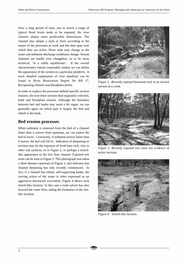
Bed erosion processesWhen sediment is removed from the bed of a channel
faster than it arrives from upstream, we can expect the
bed to lower. Conversely, if sediment arrives faster than
it leaves, the bed will fill in. Indicators of deepening or
incision may be the exposure of fresh bare rock, clay or
other soil surfaces, as in Figure 2, or perhaps a trench-
like appearance to the low flow channel. Exposed tree
roots can be seen in Figure 3. This photograph was taken
a short distance upstream of Figure 2, and indicates that
channel deepening has only recently commenced. In
fact, if a channel has robust, self-supporting banks, the
carving action of the water is often expressed as an
aggressive downward excavation. Figure 4 shows such
trench-like incision. In this case a road culvert has also
focused the water flow, aiding the formation of the slot-
like incision.
Figure 2. Recently exposed basement rock in an incised
section of a creek.
Figure 3. Recently exposed tree roots are evidence of
active incision.
Figure 4. Trench-like incision.
2

In an incising channel, knick points often form. A knick
point is a place at which the longitudinal (lengthways)
slope of the bed suddenly steepens. In severe cases a
headcut or waterfall can form (Figure 5). A headcut is
characterised by an overhanging vertical face with water
falling (from the brink-point) into a deep hole called a
plunge-pool. Powerful rotating currents called wall-jets
or reverse rollers nibble away at the earth or rock face at
the base of the waterfall. The top of the unsupported
overhang eventually fractures and falls in and the
waterfall moves further upstream. Banks bordering the
plunge pool are prone to collapse due to horizontal
circulating currents or eddies that move upstream at the
edges, and to deepening of the pool. Material that falls
into the plunge pool is swept downstream. For these
reasons, the channel below a headcut is often wider as
well as deeper than the channel upstream.
Figure 5. A typical headcut.
Both knick points and headcuts gradually move
upstream and release sediment into the river system.
This movement may be imperceptible, but has been
known to proceed at the rate of tens of metres per year,
depending on the cohesiveness of the channel material
and the seasonal flow pattern. Headcuts progress until
the entire bed of the channel reaches some stable
uniformity in its overall slope. River Restoration Report
No RR 9, Stream channel analysis, discusses bed slope
profile in more detail.
Causeways
Causeways, with or without culvert pipes, are a type
of crossing commonly placed across streams. When
water spills over the top of a causeway, erosion
processes similar to head-cutting can occur on the
downstream side. Figure 6 shows an attempt to
stabilise a causeway eroded by these processes.
On their upstream side causeways behave like
weirs, slowing the water and encouraging the
deposition of sediment. The culverts may become
buried or partially filled with sediment. This in turn
tends to increase the frequency with which water
flows over the top of the causeway. The form and
height of a crossing are therefore important factors
in finding an effective design.
Culvert pipes under causeways or other crossings
concentrate stream flow, forming a water-jet at the
outlet that can contribute significantly to erosion
downstream.
Figure 6. A causeway showing ongoing attempts to
stabilise the erosion caused by floods overtopping the
road and water jetting through culverts.
Managing bed erosion
The decision to alter the bed of a stream channel should
not be done in an ad hoc manner. Apart from legal
considerations, doing an accurate survey of the bed
profile and channel cross-sections is an essential task
before deciding on a course of action. Details of how to
conduct a stream channel survey are outlined in River
Restoration Report No RR9, Stream channel analysis.
Water and Rivers Commission Waterways WA Program. Managing and enhancing our waterways for the future
3

Water and Rivers Commission Waterways WA Program. Managing and enhancing our waterways for the future
4
The survey enables the problem to be seen in the right
context, and helps to determine its cause and possibly to
predict its outcome. Sometimes calculations can be
made to predict the amount of change that is likely to
occur. During a survey, some measure of the rate of
erosion is also useful. For example, metal erosion pin(s)
can be hammered into the face of a headcut (Figure 7).
The amount of pin exposed reveals the amount of soil
lost at the site over a period of time. By keeping a record
of the rate of exposure of the pin, the erosion rate can be
calculated. Pegs on a bank, or a rope stretched across a
headcut face above the flood peak, can also be used. In
some situations paint may be used to determine where
erosion hot spots are located.
With this type of information, the proposed solution to a
bed erosion issue can then be based on a design that
takes into account the behaviour of the flow, rather than
guesswork. As mentioned, the proposed solution may
also need to meet certain statutory requirements. The ‘do
nothing’ option should always be considered. For
example, trying to stabilise a headcut may not be
necessary, if just upstream there is a rock bar which will
naturally limit its progress.
Figure 7. Shows an erosion pin in a creek bank. More of
the pin is exposed as the bank surface erodes away.
There are essentially three options for stabilising a
headcut:
1.Back flooding, perhaps through the construction of a
‘riffle’ downstream. This may work if the height of the
overfall is not too great and a riffle, rather than a dam,
is sufficient to achieve the result.
2. The headcut itself may be converted to a rocky riffle
or rock chute with a more stable bed slope. The design
should ensure that flood flows do not erode a bypass
channel around the structure. Simply dumping rocks
or rubbish into the pool below the headcut is of
negligible value in the long term as the erosion face
moves upstream. It may even aggravate bank erosion
downstream.
3.In some special cases, for example hill slope gullies, it
may be possible to divert the water flow around the
site of the headcut, spreading the flow or creating a
new channel with a reduced slope. Care must be taken
with this course of action since the problem may
simply be shifted to another location. The design of
various bed control structures is outlined in River
Restoration Report No RR 10, Stream stabilisation.
A fourth course of ‘action’ is no-action; the incision
process is allowed to continue its progress unhindered. A
sound knowledge of the channel form and processes is
required to understand what may be the eventual
outcome of a ‘do-nothing’ approach.
Bank erosion processesBank erosion may affect one or both banks of a channel
reach, causing the channel to widen. Alternatively it may
simply contribute to the migration process of meanders,
without necessarily changing the size of the channel.
This happens if sediment deposition on one bank offsets
erosion on the opposite bank to maintain a stable
channel width. In our largely destabilised river channels,
the sediment derived from eroding banks is often
associated with the infilling of river pools and is of real
concern for the health of the river system downstream.
Channels become wider and shallower, perhaps even
dividing into many minor channels.
Three broad types of bank erosion are discussed here:
gradual erosion, erosion due to obstructions and bank
collapse.
Gradual erosion
Stream banks can erode away in an even and steady
manner along their length, simply by the action of water
and sediment rushing past and ‘snatching’ away loose
soil particles. Evidence of general and regular abrasive
erosion is a bare soil surface where vegetation has
difficulty getting established, or perhaps stain marks, or
a lower limit to patches of lichen or moss. Erosion
hotspots may be detected by using erosion pins or by
applying small patches of paint to the banks and seeing
Water and Rivers Commission Waterways WA Program. Managing and enhancing our waterways for the future
5
which ones wear away first. Gradual erosion is often
natural and acceptable but if it is proceeding too fast, bed
or bank protection may be needed, or the flow velocity
may need to be reduced.
Slowing the flow can be achieved by increasing the
‘roughness’ of the channel. The amount of ‘slowing’
may not need to be very great. Often planting with
appropriate plant species or allowing vegetation to
naturally re-colonise the banks, perhaps by excluding
stock, can be sufficient. The installation of riffles made
of local rocks or woody debris may also be appropriate
(Figure 8).
Slowing the water by increasing channel roughness also
increases the types of habitat available for aquatic life in
the otherwise scoured channel bed. It should be
remembered that where water flow is slowed, the depth
tends to increase and water can take a path around the
area of roughness. However since sediment deposition
is favoured where water slows down, this will tend to
reduce the depth over time. In either case there will be a
tendency for the flow to bypass the ‘roughened’ area if a
less resistant path can be found.
Figure 8. An artificial riffle constructed in a
straightened section of a creek is intended to slightly
slow water and sediment movement, and to create
habitat for aquatic fauna.
Obstructional erosion
The second common erosion process occurs where
objects within the channel, for example logs, debris,
rock or sediment bars, deflect flow into a bank. An
object can focus the flow into a more powerful water jet.
The erosion rate is increased where the flow is focused,
and a ‘kink’ may form in the channel, perhaps eventually
leading to a significant change in the position of the
channel. A simple and inexpensive management option
may be simply to re-orient the obstruction, rather than
removing it completely.
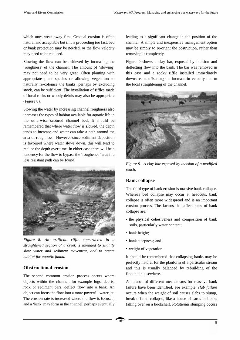
Figure 9 shows a clay bar, exposed by incision and
deflecting flow into the bank. The bar was removed in
this case and a rocky riffle installed immediately
downstream, offsetting the increase in velocity due to
the local straightening of the channel.
Figure 9. A clay bar exposed by incision of a modified
reach.
Bank collapse
The third type of bank erosion is massive bank collapse.
Whereas bed collapse may occur at headcuts, bank
collapse is often more widespread and is an important
erosion process. The factors that affect rates of bank
collapse are:
• the physical cohesiveness and composition of bank
soils, particularly water content;
• bank height;
• bank steepness; and
• weight of vegetation.
It should be remembered that collapsing banks may be
perfectly natural for the planform of a particular stream
and this is usually balanced by rebuilding of the
floodplain elsewhere.
A number of different mechanisms for massive bank
failure have been identified. For example, slab failure
occurs when the weight of soil causes slabs to slump,
break off and collapse, like a house of cards or books
falling over on a bookshelf. Rotational slumping occurs
Water and Rivers Commission Waterways WA Program. Managing and enhancing our waterways for the future
6
where a section of bank slumps along a curved cross-
section, like a bar of soap slipping down the curved
inside surface of a bathtub. Rotational slumping usually
occurs in more cohesive soils. Trees can prevent this
through a cantilever strengthening effect.
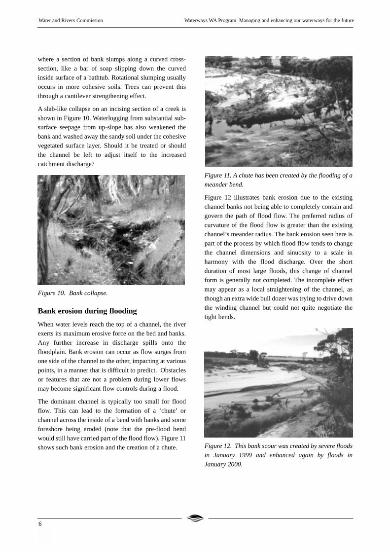
A slab-like collapse on an incising section of a creek is
shown in Figure 10. Waterlogging from substantial sub-
surface seepage from up-slope has also weakened the
bank and washed away the sandy soil under the cohesive
vegetated surface layer. Should it be treated or should
the channel be left to adjust itself to the increased
catchment discharge?
Figure 10. Bank collapse.
Bank erosion during flooding
When water levels reach the top of a channel, the river
exerts its maximum erosive force on the bed and banks.
Any further increase in discharge spills onto the
floodplain. Bank erosion can occur as flow surges from
one side of the channel to the other, impacting at various
points, in a manner that is difficult to predict. Obstacles
or features that are not a problem during lower flows
may become significant flow controls during a flood.
The dominant channel is typically too small for flood
flow. This can lead to the formation of a ‘chute’ or
channel across the inside of a bend with banks and some
foreshore being eroded (note that the pre-flood bend
would still have carried part of the flood flow). Figure 11
shows such bank erosion and the creation of a chute.
Figure 11. A chute has been created by the flooding of a
meander bend.
Figure 12 illustrates bank erosion due to the existing
channel banks not being able to completely contain and
govern the path of flood flow. The preferred radius of
curvature of the flood flow is greater than the existing
channel’s meander radius. The bank erosion seen here is
part of the process by which flood flow tends to change
the channel dimensions and sinuosity to a scale in
harmony with the flood discharge. Over the short
duration of most large floods, this change of channel
form is generally not completed. The incomplete effect
may appear as a local straightening of the channel, as
though an extra wide bull dozer was trying to drive down
the winding channel but could not quite negotiate the
tight bends.
Figure 12. This bank scour was created by severe floods
in January 1999 and enhanced again by floods in
January 2000.

Water and Rivers Commission Waterways WA Program. Managing and enhancing our waterways for the future
7
Managing bank erosion
There is ample evidence that riparian vegetation has a
tremendous capacity to resist the ‘watery’ forces causing
bank erosion. Sedges can be seen lining the bank below
the near scour shown in Figure 12 and this demonstrates
the resilience of certain types of vegetation under
extreme flood conditions. The flood overtopped the high
bank in the background, but the sedges stayed in place.
You can see the massive erosion taking place around the
sedge community. Revegetation of banks and exclusion
of stock are currently the primary stabilising techniques
for unstable banks. Streamline fencing for controlling
stock access to channel banks and foreshores is an
essential part of a strategy for erosion reduction.
Protection of the base (toe) of the bank may be required
if scouring is undermining the bank. Methods to reduce
the bank height or slope may be appropriate if the bed is
incising. In situations where waterlogging is weakening
the soil structure, remedies that address up-slope
recharge may be needed. However, as we will see, this
restoration strategy does not always work when it comes
to extreme flooding.
Floodplain erosionWe now turn to the effect of water that over-tops a
channel and moves across the adjacent floodplain. It is
clear that the potential for such erosion and
sedimentation is an issue that has not been adequately
factored into many plans for ‘exploiting’ floodplains.
The infrequency of large floods can lead to a complacent
and perhaps overly optimistic approach to floodplain
use. Unfortunately the rare, catastrophic flood can have
long lasting impacts on the structure of the floodplain.
The clearing of catchments for agriculture and urban
development has aggravated floodplain erosion for two
reasons, firstly due to changes in surface and
groundwater discharge and secondly due to loss of soil
strength.
The seasonal pattern of surface and ground water
discharge has been dramatically altered in many
catchments. This has been summarised as ‘more water,
more often, moving faster’. In many parts of Western
Australia it has also meant saltier water. The net result of
these increases is that the pre-existing channel
dimensions (width, depth and slope) are insufficient to
convey the more frequent flood flows. The channel
commences to deepen, widen or to change its planform,
and maybe all three.
Extra sediment enters the channel from eroding gullies,
banks and hill slopes. Where this sediment is deposited,
the channel becomes shallower, forcing more water
across the floodplain. The change in discharge pattern is
the justification some land managers use for holding
those who live upstream responsible for the erosion and
sediment problems that are happening downstream.
The second impact of clearing has been to seriously
weaken the structural integrity of floodplain and
foreshore soils by reducing the surface roughness,
lowering its frictional resistance and thereby increasing
the water velocity over a reach. The velocity and depth
of water flow largely determines its erosive power.
During periods when flood waters flow across the
floodplain, the degraded ground cover and understorey
plants (usually annual pastures or weeds) are no longer
sufficient to hold the soil surface in place. In addition,
the deeper reinforcing of the soil layers by tree roots is
lost as the trees disappear and the roots rot away. High
salt levels exacerbate these effects. All these factors
combined, lay some of the responsibility for excessive
erosion with land managers, regardless of where they
live along a waterway.
Managing floodplain flow
Floodplain management methods in rural and urban
catchments often do not properly cater for stream
hydraulic or ecological function. Most efforts at erosion
control are ad hoc and a result of ‘crisis management’ or
‘theories’, more than informed design or foresight.
Highly engineered drains sacrifice almost all ecological
function in favour of hydraulic efficiency.
The erosion potential of a channel and floodplain is
influenced, in part, by the degree of bed, bank and
floodplain ‘roughness’. Roughness is often specified by
a factor known as ‘Manning’s n’ (for more information
on ‘Manning’s n’, see Stream channel analysis Report
No RR 9). The roughness and/or dimensions of the
channel should be maintained at a level (or equivalent
Manning’s ‘n’ value) appropriate to its long term flood
history. Typically the threshold dimensions of a channel
are those corresponding to the flood that occurs, on
average, every 1 to 2 years. The effect of catastrophic
floods, that is those rare events that can produce major

failure of the channel system, must also be considered in
our recently cleared catchments.
A channel with high roughness compared to its adjacent
floodplain – for example a channel congested with
vegetation, excess sediment and debris accumulated
over many years of low annual floods, but cleared in the
flood fringe - is a potential site for an erosion feature
called an avulsion. An avulsion occurs when water
escapes out of one channel and creates a new channel or
scour. The eroded sediment is dumped somewhere
downstream. Natural restrictions in the channel can also
cause avulsions. Man made structures, including
crossings and restoration works, which restrict or focus
flow into unstable areas, should be avoided.
A closer look at Figure 1 reveals an avulsion where flood
waters failed to negotiate an irregular meander on the
Dalyup River, cutting across in a straight line to its
junction with the West Dalyup River. In order to
maintain optimum discharge capacity or water
conveyance, and therefore reduce the risk of an avulsion,
some sensitive re-arrangement may be an option.
Channel conveyance can be maintained by selectively
repositioning debris, pruning vegetation and excavating
accumulated sediment if it is causing significant
congestion. Any proposal to remove vegetation,
sediment or large woody debris from the channel should
be assessed in context with the entire stream reach. For
example, large woody debris could be perceived to be
congesting the channel, when actually a causeway
downstream is causing back flooding. Removal of
obstructions should be localised and large scale clearing
using bull dozers should not be undertaken, although
this action is often and seriously suggested.
When water is flowing over the floodplain, the
distribution and nature of vegetation patches, pasture,
hedges, plantations and barriers is an important factor in
influencing the location and degree of floodplain
erosion. Vegetation is the most basic and preferred
‘engineering’ material for management of floodplain
erosion and sedimentation. Less obvious native plants
(the ones without large brightly coloured flowers) such
as sedges and samphires may emerge as the key
ingredients for stabilising our waterways, even in highly
saline areas. Concrete, rubbish and old car bodies are
relegated to the bottom of the list of useful resources.
Vegetation is likely to be the cheapest option and the
most flexible and efficient in its application. It may not
be necessary to revegetate an entire floodplain to prevent
excessive erosion. Agricultural activities can coexist
with natural river processes with an acceptable level of
risk, provided a design approach is taken.
There is a good case for maintaining alternate or
secondary channels formed by previous floods, as a
form of ‘safety valve’ for future events. These channels,
usually of smaller dimensions than the main channel, are
a common feature and may be short cuts across bends or
diverge from the main channel for some distance
(anabranch), even competing with the main channel
during lesser discharges. The cross-sectional shape of
the channel determines where floodwaters exit and enter
the main channel and these points are often critical
erosion sites. A knowledge of the likely pathways that
flood flows may take across a floodplain is an essential
basis for good protection and maintenance measures.
A farm management or restoration plan should consider
old channels and the potential for new channel
formation, as well as the existing planform of the river.
Features that were initiated in earlier floods, such as
depressions, sediment highs and obstacles to the flows
should also be taken into account. These features may be
assessed by inspecting aerial photographs, walking the
river, and if necessary, by conducting a cross-section
level survey of the floodway. Figure 13 gives a
perspective of the path of a flood that may not be fully
appreciated at ground level.
Figure 13. The Dalyup River Bridge area shortly after
the floods of January 2000. The path and effects of the
flood across the floodplain are clearly seen from the air.
Water and Rivers Commission Waterways WA Program. Managing and enhancing our waterways for the future
8 W R
Water and Rivers Commission Waterways WA Program. Managing and enhancing our waterways for the future
9
The natural tendency of stream flowto wanderBends in rivers of all sizes are such common features
that their nature and relationship to erosion and
sedimentation processes needs some explanation. This
section discusses some critical aspects of the
development of river bends.
Bends in rivers occur in single or multiple channels and
at many scales. Bends within bends are a common
occurrence. They are not simply a result of diversion of
flow around particular obstacles, but are more
fundamentally a result of the behaviour of a stream of
water interacting with a resistive but erodible pathway.
Persistent and developing river bends can over-ride or
enhance local ‘wiggles’ caused by obstructions, to
produce the smooth, snaking path we usually associate
with a stream. Once a flow pathway is established there
are a number of factors that determine how persistent
that particular path is, and the manner in which it shifts.
The mechanisms influencing the formation of river
bends are only now being more clearly understood to the
extent that they can be modelled and their theoretical
movement predicted. It is also clear that river restoration
efforts need to work with, and not against, stream
meandering if erosion is to be well managed.
The ‘wiggliness’, or sinuosity of streamchannels
We define stream sinuosity as a measure of the curvature
of a section of stream channel. At one extreme, a channel
can be straight (lowest sinuosity) and at the other
extreme it can have many gathered loops (extreme
sinuosity). A measure of the sinuosity between two
points along a channel is found by dividing the actual
channel length, as the fish swims, by the length of a
straight line joining the two end points, usually
measured as the down valley distance.
Channel lengthSinuosity = ----------------------
Straight line distance
The lowest practical measure of sinuosity is one (1) and
this means that the channel is straight or takes the most
direct path down the valley.
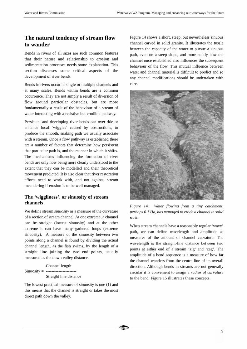
Figure 14 shows a short, steep, but nevertheless sinuous
channel carved in solid granite. It illustrates the tussle
between the capacity of the water to pursue a sinuous
path, even on a steep slope, and more subtly how the
channel once established also influences the subsequent
behaviour of the flow. This mutual influence between
water and channel material is difficult to predict and so
any channel modifications should be undertaken with
care.
Figure 14. Water flowing from a tiny catchment,
perhaps 0.1 Ha, has managed to erode a channel in solid
rock.
When stream channels have a reasonably regular ‘wavy’
path, we can define wavelength and amplitude as
measures of the amount of channel curvature. The
wavelength is the straight-line distance between two
points at either end of a stream ‘zig’ and ‘zag’. The
amplitude of a bend sequence is a measure of how far
the channel wanders from the centre-line of its overall
direction. Although bends in streams are not generally
circular it is convenient to assign a radius of curvature
to the bend. Figure 15 illustrates these concepts.

Figure 15. Defining wavelength, amplitude and radius of
curvature.
For example, if the channel length shown in Figure 15 is
1.8 km long and the straight-line distance (dotted line) is
1.2 km, then the sinuosity (S) of the reach can be
calculated as:
1.8S = -------- = 1.5
1.2
If significant change in channel form is evident, then
changes in sinuosity may be used as a measure of the
response of a stream to pressures from the shift in the
hydrological balance.
The path of high velocity flow
Turbulent behaviour in streams is influenced by such
factors as flow velocity and channel roughness. The
result is that the water does not move at the same speed
at all points throughout any cross-section of the flow.
Figure 16 illustrates this.
Figure 16. The path of high velocity flow.
Slowing of the water by friction or drag near the stream
bed and banks, creates a core region away from the
channel perimeter of greater than average velocity. The
position of this ‘core’ and its size will, of course, vary
with the flood level, but it is an important characteristic
of any stream, large or small. This path of highest
velocity is not constrained to stay along the centre-line
of the channel and in fact it is most unlikely to maintain
such a position due to the many hindrances which nudge
it one way or the other. The path of highest velocity is
usually associated with the channel thalweg, the line
joining the lowest points of successive cross-sections of
a channel (see also Figure 20).
The behaviour of the ‘core’ or ‘thread’ of high velocity
is considered a critical factor in the initiation and
development of river bends. Since water is
incompressible, the deflection of a few litres around any
one obstacle is felt throughout the entire cross-section,
much as someone blocking your path along a busy
footpath causes you to veer to one side and you in turn
cause others to veer. At the same time the shop windows
and the roadway confine the meandering. The winding
path of the high velocity thread can be thought of as an
average response of the water particles to all obstacles
including other faster or slower parts of the water body
itself.
In addition, loose material forming the bed and banks
not only deflects the water but is itself swept to quieter
areas of the channel. Thus a pathway for the higher
velocity flow may be able to persist for a long period of
time. The persistence of a feature is a measure of its
‘stability’. An important factor here is the cohesiveness
of the material of which the channel and floodplain are
constructed.
Figure 17 shows a ‘wiggle’, or scour, in the path of river.
It was created in a few days by a major flood event. This
change in the curvature of the meander would
undoubtedly have continued if the floods had persisted,
but may not lead to a long lasting change to the position
of the main channel during normal periods of flow.
Water and Rivers Commission Waterways WA Program. Managing and enhancing our waterways for the future
10
wav
elen
gth
Amplitude
Radius ofcurvature
Lowvelocity
Highvelocity

Water and Rivers Commission Waterways WA Program. Managing and enhancing our waterways for the future
11W R
Figure 17. A bank scour demonstrates that the sinuous
motion of the flood flow was not in harmony with the old
channel.
Bend development
As water moves along a newly created, straight drainage
channel, sinuous ‘wiggles’ are present in the turbulent
flow. These promote the accumulation of sediment in
bars whose position typically alternates from one side of
the channel to the other. These bars can become
colonised by vegetation if conditions are favourable.
Erosion is strongest at the outside of the bend in between
bars. The development of stream sinuosity is thought, by
some researchers, to be intimately tied to the
development of sediment deposits within a channel.
Figure 18 gives an example of a common alternating
pattern of sediment deposition.
Understanding the relationship between both deposition
features and erosion features is therefore important to
restoration design. For example, although an eroding
outer bank of a stream bend may attract your initial
attention, erosion control may be achieved by
manipulating the sediment deposited on the inside of the
bend or point bar. This may be a simpler and adequate
solution to an immediate problem.
Figure 18. A section of a small channel showing the
formation of alternating sediment bars after a storm
event. This suggests there were areas of high velocity
and low velocity associated with the sinuous path of the
high flow.
Motion around a bend
There is a distinctive ‘feel’ about driving a car around a
tight bend (on a road, not in a river, although that is quite
distinctive also). You instinctively grip the wheel and
exert energy to maintain your balance by leaning
towards the inside of the bend. This is because your body
is objecting to changing course and inclined to continue
in a straight line. To moderate this effect we apply the
brakes to achieve a more comfortable speed. There is an
optimum bend radius that balances allowable speed
against the effort you expend when turning. Road
engineers design the radius and cross-sectional slope of
the road bend with this speed in mind.
The situation is similar for river flow, but the erodible
banks allow the flow to partly design its own highway.
The channel cross-section moves to the form that is the
most efficient conserver of energy. In one sense, the bed
and bank of the channel itself, applies the brakes to the
flow. For a car, the brake pads and tyres and to a lesser
extent, the road, wear away, but in a stream it is only the
bed and banks that wear away, not the water.
And as a car has a tendency to roll on a bend, water is
also inclined to tumble, but being a liquid, the tumbling
motion results in a spiralling secondary current. The
secondary current is able to move sediment sideways
across the bed as well as downstream.
The fact that the water, like a driver, does not respond
easily to a change in direction, can be seen where flow is

Water and Rivers Commission Waterways WA Program. Managing and enhancing our waterways for the future
12
constrained to move around a tight meander and there is
active erosion at the outside exit end of the bend. In
floodplains that are easily eroded, the position of the
bend tends to move down and/or across the valley,
producing asymmetrical meanders, as illustrated in
Figure 19.
Figure 19. Bend migration in alluvial channels.
Understanding this process helps the river manager to
appreciate where the erosion stress points are likely to be
along a channel. The relative position of the path of
highest flow velocity in the cross-section, and the
strength of the secondary currents, are important in any
particular reach. It is the relationship between the
curvature of the path of high water velocity and the
curvature of the channel that really influences the
process of bend erosion and deposition. This
relationship varies for different flood levels.
The stress on a stream channel, at a bend, does not occur
where the ‘rubber meets the road’, but where the ‘water
meets the bed’. This tussle tends to be concentrated in
the area at the base or toe of the bank. If the soil
cohesion is able to resist the abrasive power of the
flowing water-sediment mixture, the bank is robust. If
not, then bank scouring, and perhaps collapse, will be
very active.
The eroded material will fall to the toe of the bank and
eventually be removed by the faster flow. This material
will be carried by the secondary currents toward the
inside of the bend and be deposited on the point bars of
bends downstream.
At a bend, the cross-sectional area of an alluvial channel
takes on a characteristic asymmetric shape that can be
seen clearly in Figure 20. This highlights the powerful
partnership that exists between the velocity profile and
the stream cross-section.
Figure 20. Shows the bend features, namely the incision
along the path of high velocity and the scouring and
deposition effects of the secondary current, that create
this common cross-sectional shape.
Mathematical modelling has implied that the rate of
meander development is influenced by the local channel
curvature, particularly upstream, as well as by the
cohesiveness of banks. This suggests that alterations to
the channel curvature may speed up or slow down bank
erosion nearby. If this type of research has any message
for river managers it is that ‘works that modify channel
curvature must remain in harmony with channel
curvature upstream and downstream’.
As stream sinuosity increases, the average bed slope is
reduced. This results in a slower flow and reduced
turbulence. We observe this condition in sequences of
looping meanders on broad alluvial floodplains, where
the channel width is fairly constant and the ‘old man
river’, though sedate, is still powerful. Straightening a
channel, even when the flow has only moderate stream
power, may demand a commitment to heavy
reinforcement of banks along the entire reach. An
understanding of channel bend formation is at the very
heart of an appreciation of river erosion and sediment
deposition processes.
Meander migration
Deposition
Erosion
Erosion
Ero
sion
Dep
osit
ion Secondary currents
Point bardeposition
Thalweg

Manipulating sinuosity to control streamerosion
A number of erosion control techniques may be
applicable to a situation where the migration of a
channel, through bend erosion, threatens infrastructure.
Figures 21 and 22 show two local stabilisation measures
to control bank erosion. These techniques are explained
in detail in River Restoration Report No RR 10, Stream
stabilisation. It is also suggested that undesirable erosion
and bend development might be minimised, in some
cases, by maintaining stream curvature within a certain
range. In single channels that are free to migrate across
their floodplain, there is a tendency for the radius of
curvature of a meander bend to be between 2.3 and 2.7
times the bankfull width (see also River Restoration
Reports No RR6, Fluvial geomorphology and RR 9,
Stream channel analysis).
Allowing for natural stream sinuosity goes against the
desire of many landowners’ to shorten creek channels
with a view to increasing the rate of discharge to prevent
water logging or flooding of paddocks. The price,
usually paid in full, for straighter and hence steeper
channels is increased stream power and more destructive
erosion and sediment deposition as the flow starts to
rebuild bends.
Figure 21. Groynes diverting flow from fragile sandy
banks.
Figure 22. Bank armouring. Note that armouring a
bend with rock, for low flows, may aggravate turbulence
and erosion during high flows.
ConclusionStream channel erosion is a natural product of river flow,
but our activities can magnify the process of erosion and
it can cause problems for us when we undertake works
within a catchment. When large amounts of sediment are
eroded, further trouble results from increased turbidity
levels and the infilling of river channels, pools and even
estuaries, which affect river ecology as well as channel
structure. Understanding how water and sediment
interact to cause erosion and deposition is crucial for
good river management.
River bends are erosion and deposition ‘hot spots’ and
their complex and elegant behaviour often attracts our
attention and even our wonder. Floodplains play an
integral role in river function and these areas should not
be overlooked when dealing with erosion and
sedimentation processes.
Two basic variables, water velocity and water depth, can
be influenced to reduce channel and floodplain erosion.
Vegetation and channel form have a significant influence
on these variables. Therefore river restoration activities
need to balance and maintain a variety of hydraulic,
ecological and management functions. They require, as
does any farm or urban undertaking, a commitment to
ongoing, adaptive and informed management.
Human intervention in waterway processes, where some
degree of hydrological ‘balance’ previously existed,
must be accompanied by a commitment to a
management process to achieve a new balance without
excessive erosion. If we place a high demand on river
products and services, it is unrealistic to interfere with
13
Water and Rivers Commission Waterways WA Program. Managing and enhancing our waterways for the future

their functioning and then expect them to naturally work
things out, without unwanted impacts. The ‘do nothing’
option is likely to be unacceptably costly and
unproductive in the long run.
Managers at all levels need to understand how erosion
and sedimentation processes work. This will help to us
find a balance between drainage hydraulics and
ecological stream function, as well as any other demands
we place on a waterway. A better understanding will also
help overcome any controversy about what constitutes
appropriate river management.
GlossaryAvulsion In the context of this chapter, an avulsion
refers to the cutting off a section of land
by flood flow, or a change in the course of
water flow often accompanied by erosion
activity.
Bankfull Height of the channel forming flow, that
level is, flow that shapes the channel and leaves
its mark. Marks or clues to the height of
level include the upper edge of generally
exposed soil, lowest extent of lichens or
annual grasses, grooves in the bank and
upper edge of water stains on the bank.
Discharge The rate at which water flows. It is often
measured in cubic metres per second
(cumecs) or litres per second.
Meander The turn of a stream channel, a bend, often
associated with a distinct loop.
Planform The characteristic structure of a stream
channel, specifically in the way the
channel appears in plan view.
Thalweg The line joining the lowest points of
successive cross-sections of a channel.
Usually associated with the path of
highest velocity.
References and further readingParker, G. Andrews, E.D (1985) ‘On the time
development of meander bends’ in Journal of Fluid
Mechanics (1986), vol 162, pp 139-156.
Pen L.J (1999) Managing Our Rivers: a guide to the
nature and management of the streams of south-west
Western Australia. Water and Rivers Commission, Perth.
Schumm S.A, Harvey M.D and Watson C.C (1984)
Incised channels, morphology, dynamics and control.
Water resources publication.
Water and Rivers Commission (1999) Planning and
management: foreshore condition assessment in urban
and semi-rural areas of south-west Western Australia.
Water and Rivers Commission River Restoration Report
No. RR2, Perth.
Water and Rivers Commission (1999) Planning and
management: foreshore condition assessment in farming
areas of south-west Western Australia. Water and Rivers
Commission River Restoration Report No. RR3, Perth.
Water and Rivers Commission (2000) Water notes
WN17, Sediment in streams. Water and Rivers
Commission, Perth.
Water and Rivers Commission (2000) Water notes
WN18, Livestock management: fence location and
grazing control. Water and Rivers Commission, Perth.
Water and Rivers Commission (2000) Fluvial
geomorphology. Water and Rivers Commission River
Restoration Report No. RR6, Perth.
Water and Rivers Commission (2001) Stream channel
analysis. Water and Rivers Commission River
Restoration Report No. RR9, Perth.
Water and Rivers Commission (2001) Stream
stabilisation. Water and Rivers Commission River
Restoration Report No. RR10, Perth.
Water and Rivers Commission (2001) Planning for
waterways management: guidelines for preparing a
river action plan. Water and Rivers Commission River
Restoration Report No. RR14, Perth.
Water and Rivers Commission (2002) Recognising
channel and floodplain forms. Water and Rivers
Commission River Restoration Report No. RR17, Perth.
Water and Rivers Commission (2002) Water notes
WN27, Demonstration sites of waterways restoration in
WA. Water and Rivers Commission, Perth.
Water and Rivers Commission (2002) Water notes
WN28, Monitoring and evaluating river restoration
works. Water and Rivers Commission, Perth.
14
Water and Rivers Commission Waterways WA Program. Managing and enhancing our waterways for the future