Embed Size (px)
Citation preview

Copyright © QinetiQ ltd 2007
This document is supplied by QinetiQ for the European Aviation Safety Agency under Contract No. EASA-2006-C46
Risk Assessment for European Public Transport Operations using Single Engine Turbine Aircraft at Night and in IMC
John Bradley
QINETIQ/EMEA/IX/CR0800029/215 October 2007
54 pages
Any person finding this document should hand it to a police station or post it to the Group Security Manager, QinetiQ Limited, Cody Technology Park, Farnborough, Hampshire GU14 0LX, with particulars of how and where found. THE UNAUTHORISED RETENTION OR DESTRUCTION OF THE DOCUMENT MAY BE AN OFFENCE UNDER THE OFFICIAL SECRETS ACTS 1911 - 1989.
Requests for wider use or release must be sought from:
Intellectual Property DivisionQinetiQ LtdCody Technology ParkFarnboroughHampshireGU14 0LX

Page 2 of 54 QINETIQ/EMEA/IX/CR0800029/2
Administration page
Customer Information EUROPEAN AVIATION SAFETY AGENCY
Customer reference number EASA/2006/OP/23
Project title Study on Single Engine Airplane Operations in Instrument Meteorological Conditions or at Night
Customer Organisation EASA, Rulemaking Directorate
Customer contact Jan Novák
Contract number EASA-2006-C46
Milestone number 0003
Date due 15 October 2007
Principal Author
John Bradley 01980 662652
Technical Approval
Name M W Lewis
Post Business Group Technical Manager Heavy Aircraft Evaluation Services
Signature
Release Authority
Name A Cunningham
Post Business Group Manager Heavy Aircraft Evaluation Services
Signature
Record of changes
Issue Date Detail of Changes
1 8 August 2007 Initial Issue
2 15 October 2007 Executive Summary (last paragraph); Paragraph 7.4; Paragraph 11.15; Paragraph 12.11 and Inclusion of Appendix 1

QINETIQ/EMEA/IX/CR0800029/2 Page 3 of 54
Executive SummaryWithin Europe, certain Single Engine Turbo propeller (SET) aircraft have been cleared to conduct Public Transport operations by day and in Visual Meteorological Conditions (VMC) for a number of years. There has been considerable commercial pressure to extend this clearance to allow operations at night and in Instrument Meteorological Conditions (IMC) as already permitted in the USA and some other countries. Prior to the formation of the European Aviation Safety Agency (EASA), the Joint Aviation Authority (JAA) had conducted an extensive consultation exercise to amend the Joint Airworthiness Requirements Operations (JAR-OPS1). This process culminated in a Notice of Proposed Amendment NPA OPS 29 Rev 2, circulated in June 2004.
The requirements, as given in NPA OPS 29 Rev 2, would have allowed SET night/IMC (abbreviated to SE-IMC) operations to commence in Europe, albeit with more constraints than those required by the Federal Aviation Authority (FAA) in the USA, and the Authorities in other countries. However, while a majority of National Airworthiness Authorities (NAA) within Europe were satisfied with the proposals, a consensus could not be achieved. Consequently, when EASA became the over arching European Airworthiness Authority, it decided to suspend the rule making task and review the work done so far. It called for a full and objective risk assessment of SE-IMC operations to be undertaken by an independent expert entity with no conflict of interest towards the introduction of SE-IMC operations. In February 2007, a contract was placed with QinetiQ to undertake the work. The task was split into four phases, namely:-
a. Review the existing JAA reliability data;b. Update the data /obtain supplementary data as required;c. Conduct a full and objective risk assessment for SE-IMC operations in the European
context and;d. Review the concept of SE-IMC operations in Europe, including the proposed risk
periods and their impact on safety.
Task (a) has been completed and (b) is awaiting further clarification. This report subsumes tasks (c) and (d).
QinetiQ set up a Working Group (WG) to conduct the risk assessment and concept of operations. Firstly it reviewed the risk targets against which it was proposed to assess the safety of SE-IMC operations review. It concluded that, in the European context, the fatal accident rate from all causes should be more remote than 4 x 10⁻⁶ per flight hour (pfh), and that the fatal accident rate following engine failure should be more remote than 1.3 x 10⁻⁶ pfh. Both targets are more remote than the corresponding historical fatal accident rates for twin engine aircraft below 5700 kg.
The WG assessed risk mitigation measures independently from NPA OPS 29 Rev 2, but found that most of the topics were already covered in that document. However some specific recommendations for changes included training, aircraft certification testing and crew composition. The WG considered that a pilot and co-pilot should crew the aircraft in order to manage the high workload following a propulsion system failure at night or in IMC.
The WG then concentrated on estimating the risks arising following a power loss event on the SET aircraft and the risk mitigation measures both to reduce the probability of engine failure in the first instance and then to minimise the risks arising during a forced landing. While statistical data from aircraft incident or accident data bases was helpful in assessing historical incident and accident rates, the data were sparse in some of the detail that was sought and the accident

Page 4 of 54 QINETIQ/EMEA/IX/CR0800029/2
databases were not sufficiently detailed to determine how the overall rate was affected by operating at night or in IMC compared with day VMC.
Therefore the WG developed a theoretical risk assessment that evaluated the likely outcomes of actions taken following a propulsion system failure of a single engine aircraft at various stages in a flight both in VMC conditions as well as at night and in IMC.
The WG concluded that there was no need for a “blanket” prohibition on night or IMC flights for SET European operations. Making realistic assumptions, and assuming compliance with NPA OPS 29 Rev 2, plus the changes proposed herein, it was possible to show that the unsuccessful landing rate, following engine failure need be no greater than 1.3 x 10⁻⁶ pfh for operation at night or in IMC conditions, dependent on the assumptions made. This applied when appropriate limitations were placed on cloud ceiling and visibility and when operating from and to suitable airfields, as well as the duration of risk periods when no landing site is available within gliding range. As the fatal accident rate would in any case be smaller than the unsuccessful landing rate, the safety target was achievable, but clearly dependent on individual circumstances.
It was concluded that the operator applying for SE-IMC clearances will have to conduct a risk assessment for each of the routes for which approval is sought, using the methods given in this report. An appropriate ceiling restriction for IMC was considered to be the higher of 500 ft or the Minimum Descent Height for a non precision approach to a specific airfield and runway, with a visibility no lower than 1200 m. These minima are based on a maximum stall speed of 61 kn CAS in the landing configuration as required by Certification Specification (CS) 23, and should apply unless the applicant could show compelling arguments as to why operations at lower minima could meet the safety target.
When undertaking the risk assessment for specific routes, the applicant must explain how de-confliction with other traffic is to be achieved in implementing any risk mitigation measures. The agreement of the Air Traffic Authority to the operator’s proposal needs to be obtained.
If it is required to increase the maximum stalling speed in the landing configuration as a concession against the CS 23 requirements, the maximum that should be considered is 70 kn CAS.
Following the initial issue of this report, EASA commented on certain aspects of it. The questions raised, and the QinetiQ responses, have been added in Appendix A as a self contained package. As a result of the EASA comments, changes were made to the main body of the report as follows: A new paragraph 7.4 has been added, and changes made to paragraphs 11.15 and 12.11. Otherwise the report is unaltered, except for pagination changes.

QINETIQ/EMEA/IX/CR0800029/2 Page 5 of 54
List of contents
Title page 1
Administration page 2
Executive Summary 3
List of contents 5
1 Introduction 71.1 Background 71.2 Report Objectives 81.3 Task Information 8
2 Numerical Risk Targets 92.1 Fatal accident rate from all causes 92.2 Fatal accident rate following propulsion system failure 102.3 Estimation of fatal accident rate 112.4 Fatal accident rate night and IMC 13
3 Risk Mitigation 143.1 All risks 143.2 Risk arising from engine failure 143.3 Minimising the risk of engine failure and thrust loss 153.4 Maintenance of essential services following engine failure 153.5 Navigation aids 173.6 Aircraft handling 183.7 Airfield facilities 183.8 Survivability considerations 193.9 Operational planning 19
4 Forced landing considerations 214.1 General 214.2 Aircraft able to reach a suitable landing site 224.3 Risk periods during take off 254.4 Risk periods in the cruise 264.5 Risk period in the approach and landing 26
Page 6 of 54 QINETIQ/EMEA/IX/CR0800029/2
5 Discussion of risk assessment examples 27
6 Crew workload 28
7 Training 29
8 Air traffic control considerations 29
9 Proposed changes to NPA OPS 29 Rev 2 30
10 Comparison with other nations 30
11 Conclusions 31
12 Recommendations 33
13 References 36
14 List of abbreviations 37
15 Tables 38
16 Figures 41
A EASA Comments on Issue 1 and QinetiQ response 45
Initial distribution list 51
Report documentation page 53

QINETIQ/EMEA/IX/CR0800029/2 Page 7 of 54
1 Introduction1.1 Background
1.1.1 Within Europe, certain Single Engine Turbo (SET) propeller aircraft have been cleared to conduct Public Transport operations by day and in Visual Meteorological Conditions (VMC) for a number of years. There has been considerable commercial pressure to extend this clearance to allow operations at night and in Instrument Meteorological Conditions (IMC) as already permitted in the USA and some other countries. Prior to the formation of the European Aviation Safety Agency (EASA), the Joint Aviation Authority (JAA) had conducted an extensive consultation exercise to amend the Joint Airworthiness Requirements Operations (JAR-OPS1). This process culminated in a Notice of Proposed Amendment NPA OPS 29 Rev 2 [1], circulated in June 2004.
1.1.2 The requirements, as given in [1], would have allowed SE night/IMC (abbreviated to SE-IMC) operations to commence in Europe, albeit with more constraints than those required by the Federal Aviation Authority (FAA) in the USA, and the Authorities in other countries. However, while a majority of National Airworthiness Authorities (NAA) within Europe were satisfied with the proposals, a consensus could not be achieved. Consequently, when EASA became the over arching European Airworthiness Authority, it decided to suspend the rule making task and review the work done so far and called for a full and objective risk assessment of SE-IMC operations.
1.1.3 EASA required the review to be undertaken by an independent expert entity with no conflict of interest towards the introduction of SE-IMC operations. In February 2007, a contract was placed with QinetiQ to undertake the work. The task was split into four phases, namely:-
a. Review the existing JAA reliability data;b. Update the data /obtain supplementary data as required;c. Conduct a full and objective risk assessment for SE-IMC operations in the European
context; andd. Review the concept of SE-IMC operations in Europe, including the proposed risk
periods and their impact on safety.
1.1.4 Task (a) has been completed and reported [2]. Task (b) is awaiting further clarification. This report subsumes tasks (c) and (d), namely the risk assessment for SE-IMC in the European context, including risk periods and their impact on safety.
1.1.5 QinetiQ set up a Working Group (WG) to conduct the review. This consisted of a Safety Assessment specialist, a statistician, a Test Pilot and a Performance and Flying Qualities specialist.
1.1.6 Information sources: This report quotes numerous references citing accident and incident statistics that have been compiled by various organisations. The reader may query why data sources from different countries and different date ranges have been used when seeking to establish historic accident rates and accident patterns. The answer is that no one organisation or one country presented all the statistics in the level of detail that was needed to support the QinetiQ study, and it was necessary to take advantage of whatever relevant information was already available to progress the task. It will be seen that data has

Page 8 of 54 QINETIQ/EMEA/IX/CR0800029/2
been drawn from the UK Civil Aviation Authority (CAA) using information already published; this was supplemented by sifts that were specifically tailored to QinetiQ requests. In addition data already in the public domain from the FAA, the National Transportation Safety Board (NTSB) and the Australian Civil Aviation Safety Authority (CASA) has been drawn upon when formulating the arguments in this report. What can be stated is that all the data used come from nations that have a good airworthiness record.
1.1.7 Throughout the body of this report, the term “engine failure” has been used. This covers any failure leading to loss of thrust, be it in the core engine or its control system, damage from external sources such as foreign object ingestion, fuel starvation or a malfunction of the propeller or its pitch control system.
1.2 Report Objectives
1.2.1 The objective of this report was to conduct a full and objective risk assessment for SE-IMC operations in the European context.
1.2.2 The concept of SE-IMC operations in Europe was to be reviewed, together with the impact of risk periods on safety.
1.2.3 Risk mitigation measures were to be identified where possible.
1.2.4 Comparison was to be made with the risks incurred operating a twin engine aircraft in similar conditions to those studied for the SET.
1.3 Task Information
1.3.1 This work was carried out under EASA Contract No EASA-2006-C46.
1.3.2 The QinetiQ Task number was 590568 0007.

QINETIQ/EMEA/IX/CR0800029/2 Page 9 of 54
2 Numerical Risk Targets2.1 Fatal accident rate from all causes
2.1.1 The NPA OPS 29 Rev 2 was based on proposals that the fatal accident rate for SE turboprops from all causes should not be more frequent than 5 x 10⁻⁶ per flight hour (pfh). The QinetiQ WG commenced its independent risk assessment by considering whether or not this value was appropriate. When considering the fatal accident rate per flight hour, it is useful to consider the implications not only in relation to the travelling public, but also for the flight crews in terms of occupational health and safety. The latter will be exposed to that risk level during their work, and the UK Health and Safety Executive (HSE) guidelines given in [3] suggest that the annual chance of death of around 1 in 1000 is the dividing line between what is tolerable and what is unacceptable for any except fairly unusual occupations.
2.1.2 For an initial comparison, the fatal accident rate for large passenger carrying aircraft operated by the major western airlines provides a useful measure. The fatal accident rate per flight hour is now smaller than 0.5 x 10⁻⁶ [4].Therefore, for a pilot of such an airline, flying 900 hours per year (around the maximum permitted), the risk of being involved in a fatal accident in any one year is no greater than 900 x 0.5 x 10-6, or 0.45 x 10⁻³. Expressed in another way, there is no more than a 1 in 2222 chance of him or her being in a fatal accident each year, i.e. well within the HSE guidelines.
2.1.3 Aircrew flying on public transport operations for the major western airlines must be regarded as working at the safest end of the risk spectrum in commercial aviation. For comparison, the fatality rate per year for all commercial pilots in the USA in the period 1990 to 1999 was 80 per 100 000 pilots [5]. This translates into an individual having a 1 in 1250 chance of being in a fatal accident per year; again still better than the HSE guidelines.
2.1.4 However, in that same period, there was concern that the accident rate in Alaska was much greater than in the other States at 410 deaths per 100 000 commercial pilots [6], giving a chance of a fatal accident per year to an individual pilot of 1 in 244, i.e. nearly 4 times riskier than the HSE guideline. This accident rate caused concern, and stimulated efforts to improve flight safety. Likewise there is currently concern that US helicopters operating under Federal Airworthiness Regulation (FAR) Part 135 [7] transport operations have a fatal accident rate of 7.8 x 10⁻⁶ pfh, which is regarded as unacceptable [8] and which, for a pilot flying say 500 hours per year (which is probably not unreasonable for this type of operation), entails an annual risk of death of 1 in 256, again well below the HSE guidelines.
2.1.5 The SET proposed fatal accident rate of 5 x 10⁻⁶ pfh would entail an annual risk of death for a pilot of 1 in 400, (assuming again that 500 hours per year is realistic for a pilot operating in this sector of commercial aviation). This is probably too high a chance of death to be acceptable in the modern European context of occupational health and safety. The suggested HSE target of no greater annual risk of death than 1 in 1000 implies a fatal accident rate of 2 x 10⁻⁶ pfh. This may be too ambitious a target for improvement in this sector of commercial aviation, given that the historic fatal accident rate in the Western world is around 7 x 10⁻⁶ pfh [9]. However, the WG considered that a reasonable target for the annual occupational risk of death to an aircrew member if SE-IMC operations are approved should be no greater than 1 in 500, giving a target fatal accident rate per flight hour no more frequent than 4.0 x 10⁻⁶. It is of interest to note that the Single Engine Turbine Alliance (SETA) claims that the rate for SET aircraft is 3.79 x 10⁻⁶ pfh in the period 1991 to 1995, i.e. the overall safety target can be met [10].

Page 10 of 54 QINETIQ/EMEA/IX/CR0800029/2
2.1.6 In summary, the WG proposed that the target fatal accident rate for SET operations in Europe should be 4.0 x 10⁻⁶ pfh rather than 5 x 10⁻⁶ to better reflect current occupational health and safety expectations for aircrew. This should encompass SE-IMC operations if approved.
2.2 Fatal accident rate following propulsion system failure
2.2.1 If the fatal accident rate from all causes is targeted to be no more than 4 x 10⁻⁶ pfh, then what proportion of that can be allowed for accidents following failure of the engine? Historically, operational errors are the largest cause of accidents in modern aircraft, especially for the type of commercial operations likely to be undertaken by SET types. In the preparation of NPA OPS 29 Rev 2, the JAA used statistics provided by the UK CAA [11]. The sample was confined to the period 1980 to 1993 and restricted to Performance Group C aeroplanes engaged in public transport operations and weighing less than 5700 kg. The fatal accident rate of all types, piston and turboprop, was 4.9 x 10⁻⁶ pfh, from all causes. Of that total, engine failures contributed 1.6 x 10⁻⁶ pfh, i.e. the percentage of fatal accidents attributed to engine failure was approximately 33% of the total (1.6/4.9).
2.2.2 The proponents of NPA OPS 29 Rev 2 argued that provided that the SET fatal accident rate following engine failure was no greater than the historic rate for twin engine aircraft (1.6 x 10⁻⁶ pfh), then an equivalent level of safety would be maintained when moving to SET. However, the UK CAA considered that this was too large a proportion of the overall risk to be permitted for a single system, being based on the record of an ageing twin engine fleet, and that a significantly smaller contribution would be appropriate. The UK CAA pointed out that for large aircraft, the risk “budget” is apportioned approximately 90% for operational factors and 10% for airworthiness and, of that 10%, only one quarter is allowed for engine failure. Thus of the “all causes” fatal accident rate, only 2.5% would be budgeted for engine failure, rather than the 32% implied in the NPA.
2.2.3 However, the WG considered that the application of the large aircraft airworthiness philosophy to SET operations was not necessarily appropriate in this instance. It has largely been accepted in the discussion papers supporting NPA OPS 29 Rev 2 that the overall fatal accident rate for SET is likely to be approximately one order more risky than for large multi engine public transport operations, but that does not mean that all the risk categories must be scaled accordingly.
2.2.4 The data for twin engine aircraft cited in paragraph 2.2.1 might be regarded as somewhat dated. More recently the Australian Transport Safety Bureau has published a detailed study of power loss related accidents involving twin engine aircraft under 5700 kg in the period 1993 to 2002 [12]. This studied 63 power loss related accidents of which 11 were fatal. The ratio of fatal power loss accidents (2.4 x 10⁻⁶ pfh) to all fatal accidents (6.2 x 10⁻⁶ pfh) was 39%. This ratio is close to that established during the separate UK study of 33%, (paragraph 2.2.1).
2.2.5 The Australian study shows that overall and power loss related fatal accident rate for twins is higher than that based on the older data used by the UK CAA. Therefore the WG considered that while it might be undesirable to set accident rate targets based on legacy equipment, the reality remains that if the proposed targets for SET aircraft can be achieved, there would be a worthwhile safety improvement relative to equipment currently in use.
2.2.6 Consequently the WG considered that it was reasonable that the target fatal accident rate following engine failure should be no more than 33% of the overall fatal accident rate. By
QINETIQ/EMEA/IX/CR0800029/2 Page 11 of 54
adopting a target of 4 x 10⁻⁶ pfh as the overall fatal accident rate (see paragraph 2.1.6), the budget for engine failure, or more accurately propulsion system failure, would become 1.3 x 10⁻⁶ pfh. If this figure could be met by SET types, it would give a small improvement to the level of safety for SET compared to current twin engine equipment.
2.2.7 In addition to the fixed wing aircraft experience, the WG also considered the safety record for twin engine rotorcraft operating in the USA to FAR part 135 [13]. In the 5 year period 1993 to 1997 inclusive, the fleet flew 1.6375 million hours. There were 48 accidents, of which 9 involved failures in the drive train or control systems where there is no redundancy. This gave a rate of 5.42 x 10⁻⁶ pfh for accidents due to mechanical failure. As 28% of all helicopter accidents were fatal, the fatal rate for accidents following mechanical failure was estimated as 1.53 x 10⁻⁶ pfh. Therefore the proposed fatal accident budget for a SET, following engine failure, of 1.3 x 10⁻⁶ pfh is not unreasonable on a comparison with passenger carrying rotorcraft, following a failure in an unduplicated system.
2.2.8 In summary the WG recommends that the SET target rate for fatal accidents following a propulsion system failure should not be greater than 33% of the overall target of 4.0 x 10⁻⁶ pfh, i.e. 1.3 x 10⁻⁶ pfh.
2.3 Estimation of fatal accident rate
2.3.1 The various accident data bases can allow an overall historical measure of the fatal accident rate following a propulsion system failure to be established, but the sample sizes for commercial operation are small and tend to reduce the confidence in the results. Then, to further determine whether the historic rate is affected by operation at night or in IMC is usually not practicable without resource to source data which is often inaccessible and which would require considerable effort to locate and analyse.
2.3.2 Nevertheless, dealing firstly with the overall figures currently available; in [2], it was found that there was 1 fatal accident recorded following a SET propulsion system failure, in 6.05 million hours of commercial flying, giving a fatal accident rate following power failure of 0.16 x 10⁻⁶ pfh. With a propulsion system failure rate of 3.63 x 10⁻⁶ pfh [2] then clearly a number of successful forced landings have occurred. However, the sample size when dealing with SET is relatively small.
2.3.3 In order to obtain a different perspective on forced landing success rates, a study was made of the statistics relating to General Aviation (GA) activity in the UK. This sector encompasses aeroplanes below 5700 kg engaged in operations other than public transport. It excludes gliders and microlight aircraft. The CAA’s Aviation Safety Review [14] listed 119 fatal accidents to aircraft in this category between 1990 and 1999 inclusive. Of these, 5 (all conventional single engine light aircraft) were as a result of engine failure, and the accidents were deduced to have occurred in day VMC conditions. It was deduced from data provided by the CAA that 7.62 million hours had been flown in that 10 year period by the single engine piston GA fleet, giving a fatal accident rate following engine failure of about 0.66 x 10⁻⁶ pfh. What it was not possible to glean from this survey was the frequency of engine failure, or the number of successful forced landings.
2.3.4 To attempt a snapshot of what those numbers might be, the WG examined in detail all incident and accident reports (as applicable to GA in the UK) for the 12 month period from February 2006 onwards. While this is outside the period referred to in 6.3 above, the pattern of accidents in the GA sector do not usually show dramatic changes, and it was assumed that the average annual hours of the Single Engine Piston (SEP) GA fleet was, as

Page 12 of 54 QINETIQ/EMEA/IX/CR0800029/2
for the previous decade, around 760 000. The study for 06/07 showed that there were 45 loss of power incidents/accidents reported for the GA fleet, of which 24 were for SEPs. The following table shows the outcomes. Shown also for comparison are the multi engine piston (one incident involved an aircraft with 3 engines) and twin engine turbine.
Aircraft category
Number of engine failure or shut down events
On airfield landingsno damage
On airfield landings with damage
Off airfield landingsNo damage
Off airfield landings with damage
Single engine piston 24 4 2
Minor injuries
6 122 with minor injuries, 1 with serious injuries
Multi engine piston 14 14 - - -Twin engine turbine 7 7 - - -
Table 1 Summary of engine failure / shut down events for UK General Aviation in the period February 06 to February 07 [15]
2.3.5 What inferences can be drawn from Table 1 and what caveats must be observed when using the data? Firstly, assuming that about 760 000 hours per year is flown by single engine piston GA in the UK, then the engine failure/shutdown rate is about 32 x 10-6 pfh, i.e. roughly 3 times the rate required for SE-IMC operations.
2.3.6 It was surprising to see the number of twin turbine aircraft suffering an engine failure and shut down event. These all involved Pratt and Whitney PT 6 engine variants. However, because the data were so recent, the fleet hours to obtain the failure rates had not yet been aggregated to a high confidence level. Therefore the WG examined data made available for the whole UK twin turbine fleet of aircraft powered by PT 6 variants from 2000 to 2004 inclusive. There were 7 actual power loss events recorded (precautionary shut downs being excluded) for a fleet flying time of 80 590 hours, giving a failure rate per engine flight hour of about 43 x 10-6. While the sample includes GA (possibly less rigorous operational and maintenance standards) as well as airline operations this represents a rate about 4 times greater than the target for SE-IMC. At the time of writing this report some explanations for this discrepancy are being sought from the engine manufacturer, but have not yet been received. It is considered that this should be pursued.
2.3.7 However, reverting to the main significance of Table 1 in the context of this report; it shows that all the GA accidents following engine failure were sustained by single engine aircraft. There were no fatalities reported, although from the description of the accident involving the one serious injury sustained, the non fatal outcome must be regarded as fortuitous. Also, the apparent safety of multi engine aircraft in this 1 year snapshot must be tempered by the more broadly based statistics that show that accidents following power failure do occur with multi engines as discussed later in this report.
2.3.8 The WG considered that the following inferences drawn from a study of Table 1 might be fairly used in the SE-IMC debate, drawing on the one year snapshot of the accident record for the UK’s SEP fleet following an engine failure. It is emphasised that this is for day VMC, non-commercial operation.
QINETIQ/EMEA/IX/CR0800029/2 Page 13 of 54
2.3.9 Most engine failures were handled successfully enough to avoid injuries, in aircraft with stalling speeds around 10 knots slower than the minimum presently required for SET operations, i.e. less energy to be absorbed in a forced landing.
2.3.10 Although not directly apparent from Table 1, some aircraft damage was sustained in all of the 6 forced landings following engine failure on take-off or climb out. Following engine failure in the cruise, 5 out of 11 “off airfield” landings resulted in some damage.
2.3.11 It is likely that the preponderance of incidents involving engine failure on SE aircraft occurred in day VMC, with pilots holding a (Private Pilot’s Licence) PPL rather than a Commercial Licence in command. The cruising altitudes were also probably lower than would be used for SET operations, giving less time for field selection; also, the typical PPL will choose open terrain to fly over, but not specifically retaining a “landable” field within range.
2.3.12 Therefore, given the GA record, it seemed fair to deduce that for SET in commercial use, operating routes based on selected airfields and with emergency landing grounds retained within gliding range and with better trained aircrew, there is no reason why the GA 10 year fatal accident rate (0.66 x 10⁻⁶ pfh) following engine failure in SE aircraft should not be improved for day/VMC operations to at least 0.5 x 10⁻⁶ pfh. Indeed the record to date of 0.16 per million hours (see paragraph 2.3.2) suggests that the GA rate can be substantially reduced in the more disciplined environment of SET commercial operations. The crucial question therefore is how the fatal accident rate would change if night/IMC operations are permitted?
2.4 Fatal accident rate night and IMC
2.4.1 It was difficult to find historic indicators of how the accident rate following engine failure would be changed by operating at night or in IMC. In [6] 108 fatal and 567 non fatal crashes during commercial operations in Alaska were studied, covering the period 1990 to 1999. The accidents were sifted according to a number of criteria, including the prevailing weather and light conditions, with the following result:-
• In daylight 15% of all accidents were fatal, at night 23% of all accidents were fatal• In VMC 11% of all accidents were fatal− In IMC 45% of all accidents were fatal.
2.4.2 However, care needs to be applied in interpreting the latter figure in the context of an accident following an engine failure. This is because many of the accidents in IMC in Alaska were due to flying into the ground in adverse weather, and a high fatality rate can be expected in this type of accident. Also, as far as IMC is concerned, the engine failure may occur in IMC, but a critical factor in achieving a successful emergency landing will be the ceiling above the terrain and the visibility below cloud.
2.4.3 As it was difficult to obtaining meaningful accident statistics to quantify a risk increment due to operating at night, or with some limiting ceiling/visibility, an alternative approach was adopted. The WG developed a hazard assessment that made a rational evaluation of the risks and likely outcomes of actions taken following a propulsion system failure. This was prepared by systems engineers, in consultation with experienced aircrew, to ensure that operational realism was preserved as far as possible. The hazard assessment was developed by assessing the risk during various stages of a hypothetical SET flight, assuming
Page 14 of 54 QINETIQ/EMEA/IX/CR0800029/2
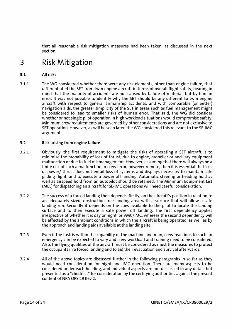
that all reasonable risk mitigation measures had been taken, as discussed in the next section.
3 Risk Mitigation3.1 All risks
3.1.1 The WG considered whether there were any risk elements, other than engine failure, that differentiated the SET from twin engine aircraft in terms of overall flight safety, bearing in mind that the majority of accidents are not caused by failure of material, but by human error. It was not possible to identify why the SET should be any different to twin engine aircraft with respect to general airmanship accidents, and with comparable (or better) navigation aids, the greater simplicity of the SET in areas such as fuel management might be considered to lead to smaller risks of human error. That said, the WG did consider whether or not single pilot operation in high workload situations would compromise safety. Minimum crew requirements are governed by other considerations and are not exclusive to SET operation. However, as will be seen later, the WG considered this relevant to the SE-IMC argument.
3.2 Risk arising from engine failure
3.2.1 Obviously, the first requirement to mitigate the risks of operating a SET aircraft is to minimise the probability of loss of thrust, due to engine, propeller or ancillary equipment malfunction or due to fuel mismanagement. However, assuming that there will always be a finite risk of such a malfunction or crew error, however remote, then it is essential that loss of power/ thrust does not entail loss of systems and displays necessary to maintain safe gliding flight, and to execute a power off landing. Automatic steering or heading hold as well as airspeed hold from an autopilot should be retained. The Minimum Equipment List (MEL) for dispatching an aircraft for SE-IMC operations will need careful consideration.
3.2.2 The success of a forced landing then depends, firstly, on the aircraft’s position in relation to an adequately sized, obstruction free landing area with a surface that will allow a safe landing run. Secondly it depends on the cues available to the pilot to locate the landing surface and to then execute a safe power off landing. The first dependency applies irrespective of whether it is day or night, or VMC/IMC, whereas the second dependency will be affected by the ambient conditions in which the aircraft is being operated, as well as by the approach and landing aids available at the landing site.
3.2.3 Even if the task is within the capability of the machine and man, crew reactions to such an emergency can be expected to vary and crew workload and training need to be considered. Also, the flying qualities of the aircraft must be considered as must the measures to protect the occupants in a forced landing and to aid their evacuation and survival afterwards.
3.2.4 All of the above topics are discussed further in the following paragraphs in so far as they would need consideration for night and IMC operation. There are many aspects to be considered under each heading, and individual aspects are not discussed in any detail, but presented as a “checklist” for consideration by the certifying authorities against the present content of NPA OPS 29 Rev 2.
QINETIQ/EMEA/IX/CR0800029/2 Page 15 of 54
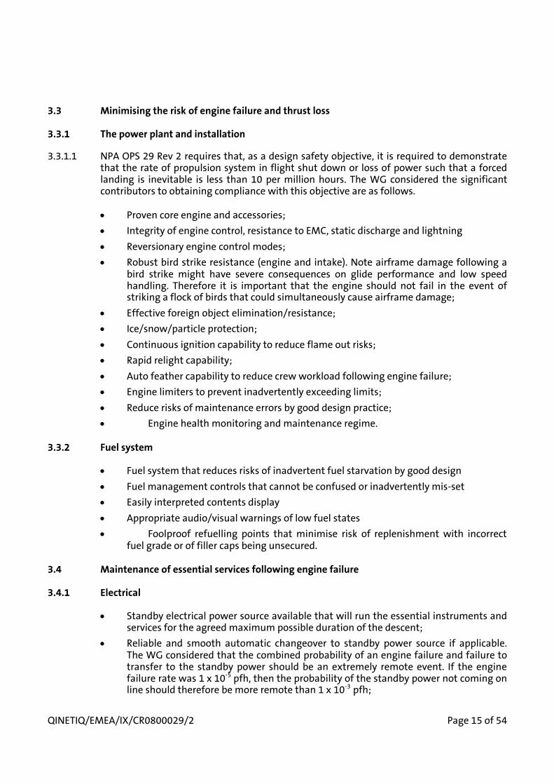
3.3 Minimising the risk of engine failure and thrust loss
3.3.1 The power plant and installation
3.3.1.1 NPA OPS 29 Rev 2 requires that, as a design safety objective, it is required to demonstrate that the rate of propulsion system in flight shut down or loss of power such that a forced landing is inevitable is less than 10 per million hours. The WG considered the significant contributors to obtaining compliance with this objective are as follows.
• Proven core engine and accessories;• Integrity of engine control, resistance to EMC, static discharge and lightning• Reversionary engine control modes;• Robust bird strike resistance (engine and intake). Note airframe damage following a
bird strike might have severe consequences on glide performance and low speed handling. Therefore it is important that the engine should not fail in the event of striking a flock of birds that could simultaneously cause airframe damage;
• Effective foreign object elimination/resistance;• Ice/snow/particle protection;• Continuous ignition capability to reduce flame out risks;• Rapid relight capability;• Auto feather capability to reduce crew workload following engine failure;• Engine limiters to prevent inadvertently exceeding limits;• Reduce risks of maintenance errors by good design practice;• Engine health monitoring and maintenance regime.
3.3.2 Fuel system
• Fuel system that reduces risks of inadvertent fuel starvation by good design• Fuel management controls that cannot be confused or inadvertently mis-set• Easily interpreted contents display• Appropriate audio/visual warnings of low fuel states• Foolproof refuelling points that minimise risk of replenishment with incorrect
fuel grade or of filler caps being unsecured.
3.4 Maintenance of essential services following engine failure
3.4.1 Electrical
• Standby electrical power source available that will run the essential instruments and services for the agreed maximum possible duration of the descent;
• Reliable and smooth automatic changeover to standby power source if applicable. The WG considered that the combined probability of an engine failure and failure to transfer to the standby power should be an extremely remote event. If the engine failure rate was 1 x 10⁻⁵ pfh, then the probability of the standby power not coming on line should therefore be more remote than 1 x 10⁻³ pfh;

Page 16 of 54 QINETIQ/EMEA/IX/CR0800029/2
• Simple/automatic load shedding procedures.
3.4.2 Flight Instruments, warning devices and checklists
• All pilot and co-pilot essential flight instruments to remain functioning (no warning flags), and to remain visible without re-balancing the lighting levels;
• Pitot heat can be maintained for the agreed maximum duration of the descent;• Stall warning to remain operative;• All pilot and co-pilot navigation and Horizontal Situation Indication (HSI) to remain
functioning (no warning flags) and to remain readable without re-balancing the lighting levels;
• Intercommunication, radios and transponder to remain functioning correctly and with their displays remaining adequately lit without rebalancing the lighting levels;
• Attention getters and warning lights can be quickly muted or dimmed;• If checklists are obtained from an electronic display, then they shall be quickly
accessed on standby power, without the need to rebalance the lighting levels.
3.4.3 Lighting
• Adequate power to maintain the external navigation lights throughout the maximum possible duration of the descent;
• Adequate power to maintain cockpit and cabin emergency lighting throughout the maximum possible duration of the descent;
• Adequate power to use the aircraft landing light for 1 minute at the end of the maximum possible duration of the descent.
3.4.4 Services
• Adequate power for 2 attempts at engine re-lighting;• Adequate power to maintain an autopilot steering or heading hold + airspeed hold
capability;• Adequate power to make one down selection of the undercarriage at the end of the
longest possible descent. The operating time on a standby system must not be excessively longer than with the normal system;
• Adequate power to make one full down selection of the high lift devices, (pausing at any intermediate setting) one full up selection and one more full down selection at the end of the longest possible descent;
• Adequate power to run any windscreen wipers throughout the longest possible descent;
• Adequate power to apply and to maintain maximum wheel braking.
3.4.5 Environmental
• Adequate power to activate the cabin and crew oxygen systems as appropriate;• Adequate power to ensure the windscreen remains de-misted and de-iced
throughout the longest possible descent;

QINETIQ/EMEA/IX/CR0800029/2 Page 17 of 54
− De icing/anti icing of airframe: emergency power supplies, unless provided by an Auxiliary Power Unit (APU) are unlikely to run these systems during a prolonged engine off descent. This has implications for how any icing clearance for SE-IMC can be supported, and is discussed further in paragraph 4.2.12.
3.4.6 Navigation
• Adequate power to maintain any selected VOR/DME/ILS fully functioning and lit throughout the longest possible descent;
• Adequate power to maintain any selected ADF facility fully functioning and lit throughout the longest possible descent;
• Adequate power to maintain all RNAV and GPS facilities and sensors fully functioning and lit throughout the longest possible descent;
− Adequate power to maintain the radar altimeter fully functioning and lit throughout the longest possible descent.
3.4.7 Demonstration that essential services can be maintained
3.4.7.1 The WG considered it essential that the effectiveness of the risk mitigation measures listed in paragraph 3.4.1 to 3.4.6 above be assessed prior to type certification for SE-IMC by an end to end test. The test would be static and ground based, undertaken in darkness as follows;
3.4.7.2 From a normal power on condition, simulating a flight at night in IMC with the appropriate services selected for that scenario and the cockpit lighting suitably balanced, the engine shall be abruptly shut down. The smooth changeover to standby power shall be demonstrated as shall the ability of the crew to maintain situational awareness, to execute the appropriate vital actions and emergency communications The ability to quickly determine the navigation solution to a simulated landing ground shall be demonstrated whilst maintaining all the services required in paragraph 3.4.2 to 3.4.6 above for the maximum period of time that a descent could last. This should include 2 attempts to relight the engine at time intervals appropriate to a high altitude attempt, followed by a second attempt at a lower altitude. As the engine lights at each attempt, it shall be stopped again to prevent battery recharge. At the end of the “descent” period, the demonstration shall include cycling of the high lift devices and full brake application as required in paragraph 3.4.4 above, and selection of the landing light as in paragraph 3.4.3 above. Following this demonstration, the condition of the standby battery shall be assessed to determine if undercarriage selection and successful operation (if applicable) would have been possible.
3.5 Navigation aids
3.5.1 A major element in mitigating risk following an engine failure will be to have an easily interpreted display to allow the crew to glide the aircraft to the nearest emergency landing site that can be reached with the height available and in the prevailing wind. The system should be capable of guiding the aircraft to the high key and then low key points for the circuit, and displaying whether the aircraft is achieving the required horizontal and vertical navigation profiles. It should also allow wind speed and direction to be readily displayed.
3.5.2 It is important that the circuit pattern advised to the crew shall be based on achieving a landing into wind if possible (in order to minimise groundspeed) unless the wind is light or there are other compelling reasons to undertake a down wind landing.

Page 18 of 54 QINETIQ/EMEA/IX/CR0800029/2
3.5.3 The integrity of the navigation aid and the validity of the database on which it depends, are of vital importance in achieving a safe approach and landing following an engine failure. NPA OPS 29 Rev 2 proposes use of an area navigation system qualified for approach accuracies and capable of being programmed with the positions of aerodromes and emergency landing sites and compliant with JTSO-C129a, Class A1 requirements. The WG believes that such equipment will meet the above requirements, but this needs to be checked on the individual equipments proposed for installation; also that the system is straight forward and intuitive to operate for this specialised purpose. As discussed in section 4, the WG also considered that for operations that demand an IMC approach, some form of continuous readout will be required, displaying the aircraft’s height in relation to the height required to glide to the threshold of the runway selected for the emergency landing.
3.5.4 When approving a type for SE-IMC the vertical and horizontal navigation aids should be assessed in flight under simulated IMC to show that they can be programmed, managed and interpreted such that a successful landing with a simulated engine failure can be achieved.
3.6 Aircraft handling
3.6.1 The aircraft should have satisfactory low speed flying qualities, with good stall warning and no tendency to wing drop at the stall. The WG considered that, during certification flying, a stall should have been demonstrated engine off and with the propeller feathered to ensure that there are no significant changes in stall or stall warning characteristics with a complete absence of propeller slipstream.
3.6.2 The maximum stall speed permitted in the landing configuration by CS 23 is 61 kn CAS at maximum weight, although it is understood that some increase in stalling speed is being considered (paragraph 3.8.3). The limitation on stall speed limits the maximum approach and landing speeds and hence the energy to be absorbed in an accident. As stated in paragraph 3.5.2, it is important to reap the safety benefit of the low stall speed by achieving an in to wind landing wherever possible so that the ground speed is as low as practicable. This will minimise the energy to be dissipated in the event of a landing accident.
3.6.3 The aircraft should possess good sideslip characteristics, to allow excess height to be lost if required. Air speed indication should not be grossly affected by pressure errors during the sideslip.
3.6.4 The aircraft should have good cross wind landing characteristics and the wheel braking system and nose wheel steering effectiveness should not be significantly diminished by the engine being inoperative.
3.7 Airfield facilities
3.7.1 The departure, destination, alternate and any emergency airfields to be used for SE-IMC need to be considered in terms of risk mitigation following engine failure. Without being prescriptive it would be expected that as the weather minima became lower, more aids for assisting the pilot to a successful landing following engine failure would become necessary. This applies to both visual aids, i.e. approach and runway lighting and markings, as well as electronic aids to support those used in the aircraft, such as ILS.

QINETIQ/EMEA/IX/CR0800029/2 Page 19 of 54
3.7.2 In making the risk assessment for a specific route (see paragraph 3.9.5) the applicant will have to address the airfield aspects as well as those of the aircraft itself.
3.8 Survivability considerations
3.8.1 The reduction of the horizontal and vertical speed components at touch down are important factors in making a forced landing more survivable.
3.8.2 It follows that the lower the stalling speed, (and hence the approach and touchdown reference speeds), the lower the energy to be dissipated. As will be shown later, this report attempts to quantify forced landing success rate, a successful landing being one with no damage or injuries sustained; it does not attempt to predict whether or not an unsuccessful landing would be fatal. Increases in stall speed and reference speeds both increase the probability of an unsuccessful “off airfield” forced landing (in that a longer obstruction free landing area is required to bring the aircraft to a stop) and, when a landing is unsuccessful, then the risk of injury or fatalities also increases.
3.8.3 It is likely that there will be commercial pressure to allow higher stalling speeds for SET above the maximum 61 kn CAS currently permitted under CS 23. While the rationale for setting 61 kn is not known (except that it is the same for FAR 23), it is difficult to find a persuasive numerical argument for setting an absolute upper limit. While FAR 23 does allow higher stall speeds provided that the design g forces in the crash case are increased, the WG felt that there were other and more unquantifiable considerations as outlined above. On balance the WG considered that a value of 70 kn, representing a 30% increase in energy relative to 61 kn was the maximum that should be countenanced at this stage in the use of SET for public transport operations.
3.8.4 If over water risk periods are accepted (see paragraph 4.4), passengers and crew should consider wearing life jackets to avoid having to locate and don them when an emergency has already developed. The adoption of simple immersion suits, as used by helicopter passengers and crew engaged in oil rig support work might be appropriate for some routes. Passengers should be briefed on dinghy deployment, boarding and use of location aids in case the crew is incapacitated.
3.8.5 Passenger and crew safety belts should feature at least a 3 point harness to give upper torso restraint.
3.8.6 The feasibility of adopting rearward facing seats should be considered.
3.8.7 Passenger pre flight briefing should cover evacuation, location of first aid and survival kit and use of aids to location, in case the crew is incapacitated.
3.9 Operational planning
3.9.1 When all the risk mitigation measures outlined in paragraphs 3.3 to 3.8 above have been considered, the other vital factors that determine the exposure to risk following an engine failure are the routes flown, the weather, cloud ceiling, and visibility minima for those routes. It has been suggested that the population density of the US is considerably lower than many European countries, and thus the potential risk from allowing SE-IMC flight is higher in Europe. However it is the case that many US operators are allowed to operate from airfields located in suburban areas, with population densities comparable to suburban areas in Europe.

Page 20 of 54 QINETIQ/EMEA/IX/CR0800029/2
3.9.2 An examination of similar sized airfields in Europe shows very few which are located in densely populated suburban areas. The majority of airfields are either located in rural areas away from the town or city which they serve, or there is a clearer path under the arrival and departure routes providing a pilot with opportunities in the event of an emergency. Thus the probability of a successful forced landing is likely to be no worse in Europe than for many of the routes flown in the USA.
3.9.3 One geographical difference between the USA and northern Europe is that the day/night distribution varies more according to the season in the latter region. Thus in winter night operations are likely to increase proportionately more than in the USA. However, as will be shown later, the WG concluded that broad brush comparisons between the USA and Europe are of little relevance, and that each individual route within Europe will need consideration on its own merits to determine whether or not it meets the safety criteria.
3.9.4 In the following paragraphs it will be seen how the WG developed a method of assigning a numerical value to the risk following engine failure. It was not considered practicable to assess whether or not a misjudged forced landing accident would be fatal, so the risk assessment was based on the estimated probability of failing to achieve a successful landing, a successful landing being defined as one with no damage or injuries sustained Therefore, when considering the results given in the following paragraphs, it should be borne in mind that the fatal accident rate would logically be smaller than the failed landing rate, but no credit has been taken for that conservatism.
3.9.5 The risk assessment methodology developed consisted of generating a risk profile for each departure and arrival airfield and runway, splitting the proposed flight into small segments, and estimating the risk if the engine failed in each individual segment. The risk profile took account of specific local conditions. The assessment of risk in each segment took in to account the height at engine failure, the position relative to the departure or destination airfield or to an emergency landing site en route, as well as to the ambient conditions (ceiling, visibility and light). The duration of each segment determined the exposure time at that estimated risk. By summing the risk for each individual segment, the cumulative risk for the flight due to engine failure could be calculated on a “per flight hour” basis. This value could then be compared with the risk target already established in paragraph 2.2.8. The risk calculations were performed using an Excel spreadsheet. This enabled changes in assumptions and sensitivity analysis to be performed quickly. For instance, by introducing a specific risk period in the en route phase into a flight, i.e. a period with no emergency landing site within range, its effect on the overall risk could be determined.
3.9.6 It will be appreciated that the process described in paragraph 3.9.5 derived a numerical solution, but based on qualitative judgement as to the likelihood of a successful forced landing being achieved. To obtain a credible result, each departure and destination airfield, each departure and arrival runway, as well as the route adopted would need to be considered individually for the prevailing weather and light conditions. It was found convenient to generate the risk profile for each case in diagrammatic form, as shown in Figure 1, and as explained in the following paragraphs.
3.9.7 Figure 1, which is for day/VMC, shows the estimated risk of an unsuccessful forced landing on the X axis plotted against the height above ground level (agl) at which the engine failure occurs on the Y axis. The risk of an unsuccessful forced landing can vary between zero and 100%, with the take-off and climb/cruise phase of the flight on the left hand side of the diagram, while the descent, approach and landing phase is plotted on the right hand side.

QINETIQ/EMEA/IX/CR0800029/2 Page 21 of 54
3.9.8 The basic shape of the diagram can be explained as follows. Dealing firstly with the take-off and climb; on the take-off, the risk is very small (the actual values estimated will be discussed later) while the aircraft is on the ground, or at a height which, on a long runway, would enable a straight ahead landing to be made within the distance remaining. Once the aircraft is at a height from which a landing outside the airfield is inevitable, there is a large risk increase, the actual values estimated for each case taking into account the terrain being over flown, as well as the ambient conditions. As height is gained the risk then diminishes as more landing options, such as a turn-back manoeuvre, become available either on to the reciprocal of the departure runway or to another runway (if one is available). As the cruise height is reached, then assuming an airfield is retained within gliding range and that there are adequate cues for a successful landing, then the risk reduces again.
3.9.9 Turning now to the right hand side of the diagram; as the aircraft descends from cruising height, the risk remains at a minimal level for as long as the aircraft remains positioned so that a glide approach can be made to either the destination (or alternate) airfield or to another airfield en route. Then, depending on whether or not the approach is visual or conducted under IFR, there will probably be a shorter or longer period of increased risk as the aircraft is positioned to terminate the flight with a normal 3 degree approach. If the engine failed in that phase, then this would result in a landing off the airfield, or in the undershoot. Once over the threshold of the runway, there would then be a marked reduction in risk again because the forced landing would be on the runway.
3.9.10 Once the risk profile outlined above has been completed for a specific route, then the process of inserting a risk value in the spreadsheet can be undertaken. On take-off, knowing the rate of climb, the period spent in each height band can be calculated. The risk of an unsuccessful forced landing can be determined from the diagram and so the cumulative risk for a flight can be obtained, for comparison with the numerical criteria.
4 Forced landing considerations4.1 General
4.1.1 A key factor in estimating the probability of an engine failure resulting in a failed forced landing is whether or not the aircraft has sufficient total energy at the point of engine failure to reach a suitable landing area and to make a safe approach. In the class of aircraft being considered the ability to trade speed for height is probably limited, so the dominant factor is potential energy, i.e. height. If the aircraft has sufficient height to glide to the landing area and to make a safe approach, then the risk of a failed landing arises from pilot misjudgement or from being denied the cues to execute the approach and landing. It is the cues and judgement factors that are made more difficult at night or in IMC.
4.1.2 If the aircraft position at engine failure is such that a suitable landing area cannot be reached with the energy available, then there is self-evidently a much increased risk of a failed forced landing. That risk will then be further increased by operation at night, in poor visibility or with a low cloud ceiling. The following discussion will differentiate between cases where the aircraft can glide to a suitable landing area and position for a safe approach and those where it can’t.

Page 22 of 54 QINETIQ/EMEA/IX/CR0800029/2
4.2 Aircraft able to reach a suitable landing site
4.2.1 Dealing firstly with the day VMC case; assuming that an engine failure occurs at an altitude that allows the aircraft to be positioned for a visual circuit at the high and then the low key points, there should be minimal risk in executing a safe power off landing on an airfield that the type normally operates from. For instance, at one extreme, the UK Air Cadets train on Grob 109 motor gliders with a glide angle of about 1 in 28 (about 4.5 nm per thousand feet). Ab initio pupils are trained to solo standard by being taught to throttle the aircraft to idle at a specific height and then to complete the flight without recourse to engine power. They also have to be able to cope with engine failure on climb out at 300 ft. Cadets go solo within about 8 hours or 50 flights. The accident rate is very low as befits a youth training organisation. It may seem irrelevant to quote the Air Cadet operation, but it represents an example of how suitable training can produce a safe judgement of “engine off” landings at the very lowest levels of experience. Of course, all approaches and landings are engine off, so that is the norm rather than an infrequent emergency case.
4.2.2 The training for engine failure in SE military aircraft continues in the UK on Hawk and Tucano aircraft. In addition to being required to execute a successful power off landing from a visual circuit, students are required to show proficiency at night and when being vectored by radar in IMC with a ceiling of 800 ft to 1000 ft; this in aircraft which typically glide 1 nm per thousand feet. They do however benefit from becoming visual with the airfield at relatively high speeds that allow some energy margin for manoeuvre. The success of this training policy is reflected in the statistics made available by the UK Defence Aviation Safety Centre for the Tucano. They show that, up until 2005, the RAF fleet had flown 315 000 hours. There were 5 occasions in flight when engine power was lost and could not be restored, 2 of which required the engine to be shut down (engine failure rate 1.6 x 10⁻⁵ pfh). All the subsequent forced landings were made on an airfield without damage or injury. Clearly the success rate implies that the all the power losses occurred in positions from which a successful landing was possible; that will not always be the case and risk periods will usually exist at some stages of a flight, as will be discussed later.
4.2.3 With the previously described military background in mind, and with the proviso of suitable training and currency for SET pilots, the WG considered that the probability of achieving a successful (no damage, no injuries) forced landing in day VMC and with the aircraft in a position to glide to the high key point of a circuit (defined as a waypoint in the RNAV), should be no worse than 99 in 100 power off landings. In other words, the risk of not achieving a successful landing was estimated to be no worse than 1 in a hundred, in the most favourable of circumstances. It also assumes that priority over any other arriving or departing traffic could be given in time to allow the aircraft with the emergency to have unrestricted use of the airspace it requires.
4.2.4 In translating the above expectations into night conditions, then the WG debated how the risk would increase. It was considered reasonable to assume that the success rate mightdecrease by a factor of 5. This was on the assumption that the aircraft position at the point of engine failure was such that it could still glide to the high key point at an airfield equipped with adequate approach and runway lighting, but that in darkness the cues available to judge the final part of the circuit would be more difficult to interpret and, without power, recovery from a misjudged position would be more difficult. The risk of not achieving a successful engine off landing at night, in the most favourable circumstances, was judged to be no worse than 5 in 100, or 1 in 20.

QINETIQ/EMEA/IX/CR0800029/2 Page 23 of 54
4.2.5 Turning now to an engine failure in IMC; but with a ceiling high enough for completion of a visual circuit. Again it is assumed that the aircraft is positioned at the point of engine failure so as to be able to glide to the high key point of a suitable airfield. With RNAV aids to guide the crew to that position, and to then break cloud and become visual with the runway should pose no greater risk than the VMC case. Provided that the low key point is also available as a waypoint in the RNAV, and is clear of cloud, and assuming that the visibility is 1500 m or more, then the WG considered that a modified visual circuit could still be achieved without any increase in risk from the VMC case, although the absence of visual references until cloud break will increase the crew workload.
4.2.6 As the ceiling gets lower, or visibility reduces, terminating the approach with a visual circuit will not be possible and an approach appropriate to IFR will be necessary. The WG considered how RNAV waypoints could be used, as suggested in [16] so that, following engine failure, the aircraft could be set up on a modified instrument approach, keeping it higher than the standard 3 degree approach to allow for the steeper gliding angle. Depending on the aircraft type this might be around 4 to 6 degrees in the clean configuration in zero wind, and up to 10 degrees in the landing configuration. A 20 knot head wind would further steepen the final approach by around 2 degrees. It would be feasible to achieve such an approach, using the ILS localizer for azimuth guidance, and using the RNAV to define emergency approach fix points at the height required to give the descent angle for the aircraft’s glide performance and headwind. The initial and final approach fix heights could be chosen so that the aircraft was assumed to be in the clean configuration up until the final fix, then gear and flap lowered to the landing position at the final fix.
4.2.7 While the procedure outlined in paragraph 4.2.6 is theoretically feasible, there are a number of practical issues to be considered in generating a rational safety argument for a public transport operation. Firstly, there is the consideration of energy management so that the aircraft arrives over the runway threshold from a straight in glide approach at a height that permits a landing within the distance available. The WG considered that this will require some form of on board continuous vertical navigation guidance, rather than simply having two approach fixes. The data base for this will require an accurate description of the aircraft’s glide performance polar, as well as being fed the correct headwind component and vertical air movement. While such a facility is technically feasible, (it is already used in high performance gliders) consideration will have to be given to system integrity, risk of data input errors and ease of pilot interpretation. Also, to give some margin for error it was considered that the energy management system should aim to put the aircraft high at the threshold, 200 ft was felt appropriate, and that this should be reflected in the required runway length available (see paragraph 4.2.10) The WG considered that a flight assessment of the proposed system would be required prior to certification for SE-IMC.
4.2.8 The second major challenge for the IMC glide approach is the selection of weather minima. The WG considered that the crew should have no less than 30 seconds of visual contact with the runway threshold in order to establish situational awareness, to make small azimuth corrections, and to achieve visual confirmation that the runway can be reached with height available.
4.2.9 The procedure outlined above could be considered a non precision approach, because of the lack of precise vertical flight path guidance. Additionally, because of the steep approach and the fact that the aircraft will be aiming to touch down well down the runway (to minimise the risk of undershooting the airfield) the glide path guidance provided normally by the approach lighting system in the final visual stages of the approach will be of limited

Page 24 of 54 QINETIQ/EMEA/IX/CR0800029/2
value. The pilot will have to maintain the glide on airspeed and attitude into the landing flare. While the concept of the Minimum Descent Height (MDH) normally associated with a non precision approach does not apply (because there is no option but to land), the WG considered that use of the published MDH for a particular airfield and runway combination to define the weather minima for SE-IMC operation would probably be appropriate, but with an overall minimum visibility and ceiling to allow 30 seconds of visual contact before touchdown. Assuming an approach speed of 80 kn (1.3 x Vstall of 61 kn) and a final rate of descent of 1000 ft/min, this equates to a ceiling of 500 ft above the runway with a visibility no less than 1200 m (50% greater than that proposed in NPA OPS 29 Rev 2). It was judged that these minima would allow the crew long enough to establish adequate visual situational awareness following descent below cloud to complete the landing. They should apply unless the applicant can show convincing evidence as to why the safety target can be achieved with lower minima. If stalling speeds higher than 61 kn are allowed, with associated higher approach speeds, then the minima would have to be increased to allow 30 seconds of visual contact.
4.2.10 The WG considered that it was necessary to schedule adequate landing distance tolerances for the above emergency IMC procedure. On the assumption that the aircraft might be 200 ft above the runway threshold instead of the normal 50 ft, then the scheduled landing distance required as factored by the JAR OPS requirements (with no retardation from the propeller in the ground pitch range), should be increased by 150 ft/ tan glide angle, i.e. an increment of 1715 ft (523 metres) for a 5 degree glide, e.g.Landing Distance Required as factored by JAR OPS = 900 m. The Landing Distance Available for the runway should therefore be at least 1423 m for an emergency IMC procedure in the example given.
4.2.11 With the above caveats applied, the WG estimated that the increase in risk relative to a VMC final approach lay in the potential for misjudging the energy management and the absence of external glide path guidance when visual with the runway. As with the night case, it was thought that the risk relative to the VMC approach with a failed engine should be increased by a factor of 5, i.e. the probability of an unsuccessful landing increased to 5 in 100. The WG considered that flight trials would be necessary prior to certification for a type to operate in IMC to confirm the realism of those estimates. These trials would be aimed at an “end to end” demonstration that using the actual navigation aids proposed by the applicant, a trained crew could programme the system for a specific route and, in the simulated engine failure case, follow the horizontal and vertical navigation guidance to achieve a safe power off landing within the calculated landing distance required. In this context a safe power off landing implies an arrival over the runway threshold within a height tolerance of 50 to 200 ft and then to stop in the distance computed in accordance with paragraph 4.2.10 above.
4.2.12 The aircraft may be certificated for flight into known icing conditions, relying on a de-icing or anti-icing system to limit ice accretion on the sensitive areas of the aerofoils. If the airframe protection systems become inoperable when the engine fails, while flying in icing conditions, then the aircraft may rapidly develop unacceptable flying characteristics. Also the performance may become degraded to the point where the assumed gliding range becomes unachievable. Therefore the applicant must show that adequate airframe anti-icing or de-icing remains available for the duration of any descent in the icing conditions for which a clearance is sought, before the clearance to operate could be recommended.

QINETIQ/EMEA/IX/CR0800029/2 Page 25 of 54
4.3 Risk periods during take off
4.3.1 In paragraph 4.2, the discussion has focused on the consequences of an engine failure when the aircraft is in a position to glide to a point where an emergency landing can be made on a suitable airfield. However, there may be periods in a flight where that is not possible, and these will need to be accounted for when assessing the overall risk on a particular route. Then, knowing the probability of engine failure and the exposure time during that stage, together with the terrain being over flown, the risk of an unsuccessful forced landing can be estimated if the engine fails in that element of the flight. Therefore the applicant may wish to develop departure patterns to minimise the risk. Those risks can then be summed for all flight stages to obtain the overall risk estimate for a particular flight. This approach is explained in more detail below.
4.3.2 If the aircraft is taking off from a runway that is much longer than normally needed for the type, then the risk period in day/VMC may be very short. For instance, up to lift off and even beyond, it may be possible to simply land ahead and remain within the take-off run or accelerate/stop distance available for that runway. As height is gained, the “land ahead” option diminishes, particularly on shorter runways and there is a risk of an off airfield landing until the minimum turn back height is reached. (It must be assumed that other departing traffic will be held until the turn back option is no longer needed).
4.3.3 During the risk period the aircraft has insufficient energy to do anything other than land ahead, possibly off the airfield. The options then for a successful forced landing will depend on the terrain and presence of significant obstructions. Perhaps the greatest risk in this phase is a turn back attempt with insufficient energy to complete the manoeuvre and with the danger of a fatal stall/spin accident occurring. The WG considered that in this phase of flight, the risk of a successful forced landing is relatively low and the probability has to be argued on a case by case basis, but the exposure period is limited, and so the contribution to the overall flight risk is smaller than might be expected.
4.3.4 If a turn back manoeuvre is undertaken, the maximum head/tail wind component permitted during take-off/landing needs careful consideration. In addition to the increased landing distance required in a tail wind, the maximum energy that the brakes can absorb might be exceeded when trying to stop the aircraft.
4.3.5 During a night take-off the risk increment again depends very much on runway length and on the terrain and obstructions if an off field landing has to be made. The WG considered that for a short period the risk of an unsuccessful outcome could be high in unfavourable circumstances. It was considered that the ability of the crew to see obstructions and to take avoiding action would be much less than in daylight, with the landing light illuminating only the area in which the aircraft is pointing. Again, the short exposure time limits the impact of this “high risk” period on the overall risk for the flight.
4.3.6 The risks during an IMC departure depend on the ceiling and visibility. Assuming the latter is no less than 500 ft/1200 m as argued in paragraph 4.2.9, then up until cloud entry, the risks were considered to be as for day or night VMC. From then on, following a Standard Instrument Departure (SID), there is a risk of an off field landing, depending on runway length, and until turn back height is achieved. It is assumed that turn back height is higher than in the VMC case because of the need for lower rate turns in IMC. The turn back procedure outlined in [16] suggested an approach on the reciprocal to the take-off heading until the runway is acquired visually, when a down wind landing is executed. The WG considered that the probability of a successful outcome to this manoeuvre would depend

Page 26 of 54 QINETIQ/EMEA/IX/CR0800029/2
on the height at which visual cues become available to correct any lateral displacement. It might be possible to use the horizontal and vertical navigation aids discussed previously to assist in the turn back manoeuvre, if the applicant proposed this as a risk mitigation measure. Pre-certification flight trials should examine this possibility. The WG assessed this phase as carrying a high risk level.
4.3.7 It was considered that, with the above considerations in mind, there were two ways of assessing the risk. Firstly, a 100% probability of an unsuccessful landing could be assumed until sufficient height has been gained for an emergency IMC approach to be made either to the airfield of departure, or to the next one en route as outlined above. If the exposure period to 100% risk is short enough, then the overall risk per flight hour might still be shown to fall within the limit proposed in paragraph 2.2.8, namely 1.3 x 10⁻⁶ pfh. For example, if half of that overall risk “budget” was allowed in the take-off and departure phase of the flight, and assuming an engine failure rate of 1 per 100 000 hours, an exposure to 100% risk of an unsuccessful forced landing could be tolerated for just under 4 minutes.
4.3.8 As an alternative to the assumption of 100% failure rate, the applicant could make a riskassessment based on each individual airfield and runway to be used. The assessment would take account of the weather minima for departure that the applicant proposes to use, the airfield location, runway layout and density of obstructions under the take-off path and the method proposed for flight path guidance, both vertical and in azimuth following engine failure. The assessment should also consider how de-confliction with other departing traffic would be dealt with. A more realistic judgement of the probability of a successful forced landing assuming an engine failure at different stages of the departure could then be made, but the WG considered that it would be important to avoid an over optimistic assessment in this critical flight phase. Examples of the proposed assessment have been given in Tables 2 to 4, which are discussed more fully later in the report.
4.4 Risk periods in the cruise
4.4.1 The methodology used to create the risk tables for specific flights can be easily adapted byinserting a risk period in the cruise phase. If for example, there was a period out of gliding range of an emergency landing site of say 5 minutes, and if the area was such that the risk of an unsuccessful forced landing was judged to be 100%, then the risk increment for that flight would be the engine failure rate times the period of exposure to that risk, or 0.28 x 10-8 x 300 x 1.0 = 0.84 x 10⁻⁶, using the engine failure rate adopted in the tables.
4.4.2 It can be seen that, depending on the flight duration, a period at very high risk could use a significant element of the “risk budget”. Nevertheless, it does allow scope for a rational assessment of the risk increment in different scenarios, and for determining whether or not compliance with the overall risk target is achieved.
4.5 Risk period in the approach and landing
4.5.1 Paragraph 4.2 dealt with the case where the engine fails in the cruise or descent phase, and, because an emergency landing ground has been retained within reach, an engine off landing is made at the level of risk that the WG judged to be appropriate for the ambient conditions
4.5.2 In the vast majority of flights the engine will not fail, and then it is necessary to consider whether or not the aircraft will routinely fly a high approach pattern so that the airfield can always be reached if the engine fails at any stage. It seems unlikely that that would be the

QINETIQ/EMEA/IX/CR0800029/2 Page 27 of 54
case, because the steep approach profile might make the routine achievement of a good stabilised approach and landing more difficult and deny the benefits of glide path guidance available from the airfield approach lighting. In other words, a procedure suitable for a remote emergency is not appropriate for day to day use.
4.5.3 The WG considered that while the approach profile to allow for an engine failure would probably be retained as long as practicable (subject to de-confliction with other traffic and permission to modify any Standard Approach Route (STAR) procedures), routinely the aircraft would most likely be allowed to descend on to the normal 3 degree approach path during the later stages of either a visual or IMC approach. Once the high approach position was abandoned, the aircraft could land short of the airfield if the engine failure did then occur. In terms of a visual circuit, it was estimated that the risk period might be 100 seconds, but on an approach in IMC it was calculated that the risk period could extend to around 4-5 minutes; the aircraft glide capability, both clean and with full flap, will affect the exposure time. A hypothetical example of the profile that might be adopted is given in Figure 2 showing how the risk periods might be calculated. However, it would be up to the applicant to describe precisely how he proposed to schedule the approach to reconcile the requirements for a good stabilised approach with an operating engine while minimising the exposure period to an off airfield landing should the engine fail during the approach. The risks associated with an emergency landing in the undershoot area, as assessed by the WG, have been allowed for in Tables 2 to 4, in a manner similar to that used in the take-off phases, but again using purely hypothetical assumptions about the aircraft’s performance.
5 Discussion of risk assessment examples5.1 Tables 2 to 4 show the completed risk assessments for hypothetical flights from and to
airfields assumed to be in relatively open country with a 9000 ft runway. In all the examples the risk has been assessed at discreet time intervals during the whole flight, rather than assuming a 100% risk throughout the take-off and departure. Table 2 is for day/VMC, derived from the Risk Profile in Figure 1. Table 3 is for night VMC derived from the Risk Profile in Figure 3. Table 4 is for night IMC with a 500 ft ceiling and 1200 m visibility, derived from the Risk Profile in Figure 4. It is stressed that the Risk Profiles used are purely hypothetical for the conditions and example aircraft selected. However, with that caveat, the risks per flight hour were calculated as 0.354 x 10⁻⁶ (day/VMC), 0.764 x 10⁻⁶
(night/VMC) and 1.286 x 10⁻⁶ (night/IMC), the values being obtained from the cell in the bottom row, right hand column for each table. It should be noted that the example flights were chosen to be 1 hour long in the cruise phase as being not untypical of the usage that might be expected in this type of operation, but if a flight was longer than that, then the risk pfh would reduce, (assuming that there was no extra high risk phase in the cruise) and if shorter the risk pfh would increase.
5.2 In all 3 examples, the risk per flight hour was smaller than the suggested criterion of 1.3 x 10⁻⁶ pfh, but the IMC example at 1.26 x 10⁻⁶ came close to it and it can be expected that in other circumstances the risk would exceed the target. It can be seen from Table 4 that the high risk in IMC was largely because of the risk of an engine failure during the departure and during the instrument approach. During the approach, the WG assumed that the aircraft would be positioned below the height required to reach the airfield (if the engine did fail) for just over 4 minutes (specifically 267 seconds in the example chosen) , in the interests of setting up a stabilised final approach at 3 degrees for the “everyday” landing with an engine operating normally. Figure 2 shows the profile that was assumed. The method of completing the risk assessment would allow the applicant to reduce that

Page 28 of 54 QINETIQ/EMEA/IX/CR0800029/2
penalty on the approach if it could be shown that the “high” glide slope could be retained as an everyday occurrence, even with the engine operating normally.
5.3 The WG envisaged that the methods used for calculating risk in the examples given could be adapted to the circumstances of individual airfields (and runways) for departure and landing. The spreadsheet used as the basis for this report is capable of being adapted for that purpose, using smaller or larger risk periods for specific phases of an individual flight as necessary. The detail of obstructions and built up areas under the departure and approach lanes could be considered and the risk periods accounted for on a realistic basis, as well as for the en route phases and for the weather minima that the applicant wished to operate in. It was considered that a fair assessment of the risks could be made, to determine if the suggested risk per flight hour criterion was or was not met in individual circumstances.
5.4 The WG considered that when conducting the “customised” risk assessments for individual routes, an important element of that assessment would be to describe the arrangements by which other traffic would be de-conflicted with the SE-IMC. For instance, if the risk assessment calls for a turn back manoeuvre should the engine fail during a departure, for how long will other departing traffic be held in case the SE-IMC aircraft does have an engine failure and require to turn back?
6 Crew workload6.1 The WG considered whether or not a 2 crew (pilot and co-pilot) operation would lead to
enhanced safety in an emergency at night or in IMC. At present an un-pressurised SET carrying less than 9 passengers may be operated by a single pilot under IFR or at night (JAR OPS 1 Paragraph 1).
6.2 The WG considered that the workload following an engine failure at night or in IMC could be considerably increased, particularly at an altitude where there is time for relight attempts as well as the need to navigate and communicate both with ground and the passengers. It could be argued that this workload applies by day as well, but the WG considered that there would be extra pressure due to being in a darkened cockpit, as well as having to fly the aircraft manually and on instruments (at least until any autopilot holds, if available, can be re-selected). The “head down” time to check the systems, attempt a relight, obtain the navigation solution for an emergency airfield, and to load shed any non essential services would be considerable. For a glide approach in IMC and low ceiling, the pilot non flying could confirm when external visual cues are acquired. In the critical phase of any forced landing the visual acquisition of the best approach path might come from either the left or the right hand seat depending on circumstances. Also, following an emergency landing, the evacuation of the passengers could be more difficult if the sole crew member was injured.
6.3 While it may be possible to envisage future advances in automation that would assist a single pilot in the flying task, the WG considered the diversity of the duties to be undertaken following engine failure indicated that a pilot and co-pilot should be considered as minimum crew for night/IMC operations with SET. This would apply unless the applicant could show convincing reasons why one pilot would suffice.

QINETIQ/EMEA/IX/CR0800029/2 Page 29 of 54
7 Training7.1 The acquisition and retention of the skills necessary to make a successful forced landing
must be considered if SE-IMC is to be permitted. Any applicant submitting a proposal to operate must include a proposal for initial and continuity training, utilising both simulator (if one exists) and actual flight experience. The latter should include simulated engine failure (power lever to zero thrust) while operating under simulated IMC at both cruising altitude and at a height suitable to initiate a turn back manoeuvre after take-off. Under both conditions the trainee should only “look up” when at the break out height, to complete the landing visually. In general NPA OPS 29 Rev 2 covers all these considerations.
7.2 The WG considered it important that a true “zero thrust” power lever setting be advised for realistic training. Experience with some military turboprop singles has shown how a misleading impression of performance can be obtained with quite small variations from a nominal power setting. Also it was considered vital that in training the rate at which undercarriage and flap travel occurs with standby systems be simulated faithfully. Standby system operating times can be much longer than with an engine driven pump functioning.
7.3 In addition it is strongly recommended that trainees experience the consequences of a real power failure when operating in a cockpit configured for night flying if a simulator is not available. This would be with the aircraft static on the ground, and from the normal power on condition, the engine would be stopped and the vital actions and subsequent actions taken to familiarise the crew with the procedures in a realistic environment. This training element is not explicitly covered in NPA OPS 29 Rev 2.
7.4 As it is considered that SE IMC requires a pilot and co-pilot, Crew Resource Management will be an important element in managing the workload safely and efficiently following an engine failure. It is important that this is emphasised during training.
8 Air traffic control considerations8.1 The WG considered that while the problems of operating the SE-IMC aircraft in isolation
have been addressed in this report, in practice, integrating the SE-IMC aircraft with other traffic needs specific consideration.
8.2 Clearly there will be many airfields used for this type of operation where the traffic density may be low enough such that the SE-IMC flight profiles, designed to minimise the risks following engine failure, can be met without disruption to other users. However, in some locations, it may be unacceptable. For example, if an applicant proposes a turn back manoeuvre to mitigate the risk of engine failure on climb out, other departing traffic may need to be held until the SE-IMC aircraft no longer needs to retain the turn back option.
8.3 It is important that when an operator submits an application for a specific SE-IMC route, the air traffic management considerations are addressed and endorsed by the Air Traffic Authority. This is also an issue for day VMC operation.

Page 30 of 54 QINETIQ/EMEA/IX/CR0800029/2
9 Proposed changes to NPA OPS 29 Rev 29.1 JAR OPS 1.247 (b):- It is suggested that reference to specific risk periods/times be removed.
This is because the risk assessment method proposed in this report allows risk periods of any duration to be factored in if the applicant so requires.
9.2 Appendix 1 to JAR OPS 1.247
9.2.1 Item (vi): - It was considered important that the Area Navigation System specified should be capable of calculating wind strength and direction for easy presentation to the crew. Also for an IMC approach a continuous presentation of actual height in relation to the height required to glide, in the prevailing wind, to the threshold should be provided.
9.2.2 Item (ix) (b):- It is recommended that power be available for 2 emergency relight attempts, one at high altitude (if appropriate), the other at a lower altitude where a second attempt might be more successful.
9.2.3 General:- Items (i) to (xii) should be reviewed in relation to the material given in this reportin paragraphs 3.3 to 3.8. It may be considered appropriate to expand or modify the content of the Appendix accordingly.
9.2.4 At the end of (ix) add: The Emergency electrical supply should have no probable or undetectable failure modes.
9.3 Appendix 2 to JAR OPS 1.247
9.3.1 Paragraph 1:- Add a new item “Minimum crew for night/IMC operation”.
9.4 ACJ OPS 1.247
9.4.1 Paragraph (b):- Add a new item “(iv) Flight crew composition”
9.5 ACJ OPS Appendix Y Crew Training
9.5.1 This should include the engine shut down training in a darkened cockpit either in a simulator or in a static aircraft as given in paragraph 7.3 of the report.
10 Comparison with other nations10.1 The proposals outlined in this report, in addition to those already proposed under NPA OPS
29 Rev 2, constitute a more rigorous set of operational requirements than those of other nations that already allow SE-IMC operation. Therefore, it may reasonably be asked why this should be. For instance, it might be argued that the co-incidence of an engine failure on a flight at night, where the prevailing cloud ceiling and visibility are such that there is no reasonable probability of a successful forced landing, is remote enough to be discounted. Therefore any further mitigation for the simultaneous occurrence of these unrelated events is not necessary. Putting hypothetical numerical assumptions in as follows gives:-
• Probability of engine failure = 10 x 10-6 pfh• Probability of flying at night = 0.5

QINETIQ/EMEA/IX/CR0800029/2 Page 31 of 54
− Probability that meteorological conditions will exist which make a successful forced landing at night impossible = 0.1.
10.2 Therefore the probability of an unsuccessful forced landing occurring is 0.5 x 10⁻⁶ pfh which meets the risk target.
10.3 However, the WG took the view that, for the above example, while the probability of flying at night might be 50% of overall fleet experience, some northern European operators will be exposed to a much greater percentage of night operations in winter. Likewise some areas will have more persistently unfavourable weather conditions. Therefore, if a clearance for SE-IMC was given on the basis of assumptions about the “global” frequency of occurrence of adverse conditions, this would expose some operators to a much higher risk level than others. This was thought to be unacceptable and consequently there was a need for a case by case examination of the risks and a rational mitigation process for them as proposed in this report.
10.4 If SE-IMC operations in Europe are commenced in accordance with the proposals in this report, it is important that the experience gained is recorded. Once safety trends have been established then it may be possible to recommend simplified criteria for further expansion of this type of operation. EASA, in conjunction with the NAAs and applicants should consider what evidence can reasonably be recorded, at the very best it is suggested that any operator shall record the SET hours logged by crews under the day / night /IMC categories.
11 Conclusions11.1 The WG concluded that there were no reasons, other than engine failure, why the SET
should be more at risk than a twin engine aircraft when operating at night or in IMC. In the European context, the target fatal accident rate for SET operating in accordance with NPA OPS 29 Rev 2, should be no greater than 4 x 10⁻⁶ per flight hour from all causes.
11.2 The fatal accident rate following engine failure should be no greater than 33% of the overall rate, i.e. 1.3 x 10⁻⁶ pfh. This target is less than the historic rate for twin engine aircraft which, depending on the sources used, was shown to be between 1.6 and 2.4 x 10⁻⁶ pfh. It was also less than the fatal accident rate of 1.53 x 10⁻⁶ pfh for twin engine helicopters operating to FAR Part 135 due solely to non engine related failures in the drive train or control systems where there is no redundancy.
11.3 In considering the likely SET fatal accident rate following engine failure, the WG drew on the statistics from UK General Aviation over the period since 1990 as well as from military experience with single engine aircraft. It concluded that in day/VMC it was reasonable to expect that SET in commercial operation should not exceed a fatal accident rate of 0.5 x 10⁻⁶ pfh. As the historic SET fatal accident rate following engine failure was actually 0.16 x10⁻⁶, this expectation appeared conservative.
11.4 The WG considered the risk mitigation measures needed both to minimise the risk of engine failure and then to maximise the probability of a successful forced landing, a successful forced landing being defined as a landing with no injuries or damage. The changes to JAR OPS, as proposed in NPA OPS 29 Rev 2, to allow SE-IMC in Europe were considered to provide reasonable mitigation against the risks of engine failure. However, the QinetiQ WG proposed some additional requirements and proposals for consideration.

Page 32 of 54 QINETIQ/EMEA/IX/CR0800029/2
11.5 It is likely that there will be commercial pressure to increase the maximum stall speed permitted in the landing configuration from the present 61 kn CAS. The WG considered that while it was difficult to establish a rational argument for defining a maximum stall speed, an increase to 70 kn would imply a 30% increase in energy at touchdown. This was felt to be the maximum that should be countenanced at this stage in the use of SET for public transport operations, given the consequent increase both in the probability of an unsuccessful “off airfield” forced landing, and of sustaining damage or injuries in an unsuccessful forced landing.
11.6 Historic accident data were not sufficient to establish how operation at night or in IMC might increase the fatal accident rate following engine failure. A method of establishing a risk assessment for an individual flight from and to specific airfields was developed. The process was based on estimating the probability of a forced landing being unsuccessful if the engine failed at different stages of the flight and how night or IMC conditions might increase the probability of an unsuccessful outcome. The assumptions made in preparing the risk assessment were important. During the departure and landing phases of a flight in particular there may be periods of significant risk depending on the terrain and the obstructions being over flown. However, provided that those periods are short enough, the overall safety target can be met.
11.7 The examples given in this report showed that there need be no “blanket” prohibition on night or IMC flights for SET European operations. Making reasonable assumptions it was possible to show that the unsuccessful landing rate, following engine failure need be no greater than 1.3 x 10⁻⁶ pfh for operation at night or in IMC conditions when appropriate limitations were placed on cloud ceiling and visibility and when operating from and to suitable airfields. As the fatal accident rate would in any case be smaller than the unsuccessful landing rate, the safety target was achievable. This assumes that a propulsion system failure rate of less frequent than 10 x 10-6 pfh can be demonstrated.
11.8 It was concluded that the applicant will have to conduct a risk assessment for each of the routes for which approval is sought, using the methods given in this report. It was considered that for an aircraft with a 61 kn stall speed an appropriate ceiling restriction for IMC would be the higher of 500 ft or the MDH for a non precision approach to a specific airfield and runway. A visibility of 1200 m was considered as the minimum for IMC operations. These values were calculated in order to allow at least 30 seconds for visual acquisition of ground features during a forced landing, and would have to be increased if higher stalling speeds and hence higher approach speeds were to be approved. The WG considered that minima calculated on the above basis should apply unless an applicant can show convincing evidence as to why they should be set lower.
11.9 The normal landing distance required, as factored by JAR OPS, should be increased to allow for the aircraft being up to 200 ft high over the threshold during an emergency landing in IMC.
11.10 In order to allow flight in icing conditions, the applicant would have to show that anti icing or de-icing of the airframe and transparencies could be maintained with the engine inoperative for the time needed for a descent from the maximum cruising altitude.
11.11 When undertaking the risk assessment for specific routes, airfields and runways, the applicant must explain how de-confliction with other traffic is to be achieved should an engine failure occur, particularly during a departure that involves a turn back. The agreement of the Air Traffic Authority to the operator’s proposal needs to be obtained.
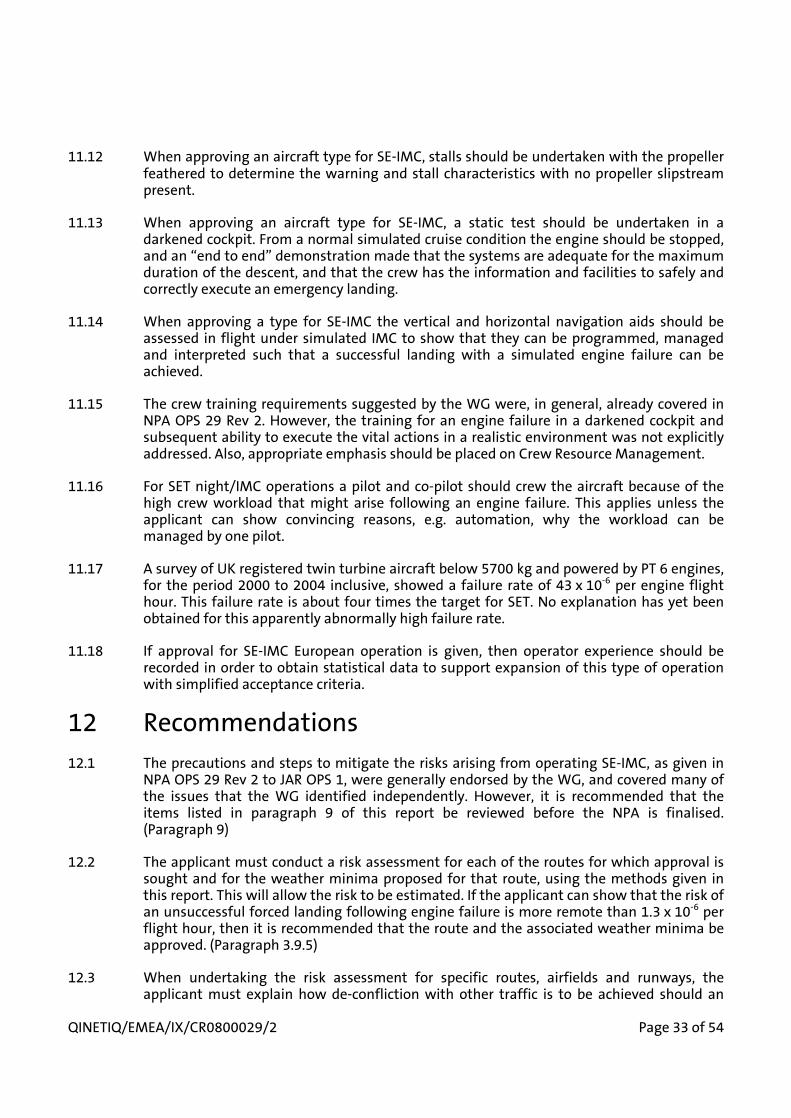
QINETIQ/EMEA/IX/CR0800029/2 Page 33 of 54
11.12 When approving an aircraft type for SE-IMC, stalls should be undertaken with the propeller feathered to determine the warning and stall characteristics with no propeller slipstream present.
11.13 When approving an aircraft type for SE-IMC, a static test should be undertaken in a darkened cockpit. From a normal simulated cruise condition the engine should be stopped, and an “end to end” demonstration made that the systems are adequate for the maximum duration of the descent, and that the crew has the information and facilities to safely and correctly execute an emergency landing.
11.14 When approving a type for SE-IMC the vertical and horizontal navigation aids should be assessed in flight under simulated IMC to show that they can be programmed, managed and interpreted such that a successful landing with a simulated engine failure can be achieved.
11.15 The crew training requirements suggested by the WG were, in general, already covered in NPA OPS 29 Rev 2. However, the training for an engine failure in a darkened cockpit and subsequent ability to execute the vital actions in a realistic environment was not explicitly addressed. Also, appropriate emphasis should be placed on Crew Resource Management.
11.16 For SET night/IMC operations a pilot and co-pilot should crew the aircraft because of the high crew workload that might arise following an engine failure. This applies unless the applicant can show convincing reasons, e.g. automation, why the workload can be managed by one pilot.
11.17 A survey of UK registered twin turbine aircraft below 5700 kg and powered by PT 6 engines, for the period 2000 to 2004 inclusive, showed a failure rate of 43 x 10-6 per engine flight hour. This failure rate is about four times the target for SET. No explanation has yet been obtained for this apparently abnormally high failure rate.
11.18 If approval for SE-IMC European operation is given, then operator experience should be recorded in order to obtain statistical data to support expansion of this type of operation with simplified acceptance criteria.
12 Recommendations12.1 The precautions and steps to mitigate the risks arising from operating SE-IMC, as given in
NPA OPS 29 Rev 2 to JAR OPS 1, were generally endorsed by the WG, and covered many of the issues that the WG identified independently. However, it is recommended that the items listed in paragraph 9 of this report be reviewed before the NPA is finalised. (Paragraph 9)
12.2 The applicant must conduct a risk assessment for each of the routes for which approval is sought and for the weather minima proposed for that route, using the methods given in this report. This will allow the risk to be estimated. If the applicant can show that the risk of an unsuccessful forced landing following engine failure is more remote than 1.3 x 10⁻⁶ per flight hour, then it is recommended that the route and the associated weather minima be approved. (Paragraph 3.9.5)
12.3 When undertaking the risk assessment for specific routes, airfields and runways, the applicant must explain how de-confliction with other traffic is to be achieved should an

Page 34 of 54 QINETIQ/EMEA/IX/CR0800029/2
engine failure occur. The endorsement of the Air Traffic Authority to the proposals must be obtained. (Paragraph 8.3)
12.4 Unless the applicant can show convincing reasons why lower minima are safe, then it is recommended that the ceiling restriction for IMC operations would be the higher of 500 ft or the Minimum Descent Height for a non precision approach to a specific airfield and runway. A visibility of 1200 m was the minimum that could be recommended. These values were calculated in order to allow at least 30 seconds for visual acquisition of ground features during a forced landing, assuming an aircraft with a 61 kn stall speed. They would have to be increased if higher stalling speeds and hence higher approach speeds were to be approved. (Paragraph 4.2.9)
12.5 Any concession on the maximum stall speed in the landing configuration (presently 61 kn) should not exceed 70 kn CAS for SET. (Paragraph 3.8.3)
12.6 The normal landing distance required, as factored by JAR OPS, should be increased to allow for the aircraft being up to 200 ft high over the threshold during an emergency landing inIMC, as detailed in this report. (Paragraph 4.2.10)
12.7 To allow flight in icing conditions, the applicant must show that anti icing or de-icing of the airframe and transparencies can be maintained with the engine inoperative for the time needed for a descent from the maximum cruising altitude. (Paragraph 3.4.5 and Paragraph 4.2.12)
12.8 It is recommended that when approving an aircraft type for SE-IMC, stalls should be undertaken with the propeller feathered to determine the warning and stall characteristics with no propeller slipstream present. (Paragraph 3.6.1)
12.9 It is recommended that when approving an aircraft type for SE-IMC, a static test should be undertaken in a darkened cockpit to simulate the consequences of an engine failure in terms of the systems behaviour and presentation of adequate information to the crew. (Paragraph 7.3)
12.10 When approving a type for SE-IMC the vertical and horizontal navigation aids should be assessed in flight under simulated IMC to show that they can be programmed, managed and interpreted such that a successful landing with a simulated engine failure can be achieved. (Paragraph 3.4.7)
12.11 It is recommended that the training for an engine failure in a darkened cockpit and subsequent ability to execute the vital actions in a realistic environment as detailed in paragraph 7 be incorporated into NPA OPS 29 Rev 2 Appendix Y. Also, training should emphasise the importance of good Crew Resource Management. (Paragraphs 7.3 and 7.4)
12.12 If the rates of travel of flap and undercarriage are slower when using a standby system than when the engine driven pump is available, then training must simulate those slower rates.(Paragraph 7.2)
12.13 For SE-IMC the aircraft should be crewed by 2 pilots unless the applicant can show convincing reasons why the workload can be managed by one pilot. (Paragraph 6.3)

QINETIQ/EMEA/IX/CR0800029/2 Page 35 of 54
12.14 The high engine failure rate (43 x 10-6 per engine flight hour) for UK registered twin turbine aircraft below 5700 kg and powered by PT 6 engines, in the period 2000 to 2004 inclusive, should be further investigated. (Paragraph 2.3.6)
12.15 EASA, in conjunction with the NAAs and applicant for SE-IMC operation should consider recording operational experience to support expansion of this type of operation using simplified acceptance criteria. (Paragraph 10.4)

Page 36 of 54 QINETIQ/EMEA/IX/CR0800029/2
13 References1. Joint Aviation Authorities, Notice of Proposed Amendment to JAR OPS-1,
Single-Engine Commercial Operations At Night/Or in IMC (RIA dated July 1, 2004 Incorporated), NPA OPS 29 Rev.2, 2004
2. Rogers, J. Review of engine reliability and fatal accident rates following loss of power for single engine and light twin engine aircraft,QINETIQ/D&TS/SES/CR0705271/1, April 2007
3. UK Health and Safety Executive Publication, Reducing Risks, Protecting People. The Health and Safety Executive Decision Making Process, 2001
4. Airclaims, Jet Operator Statistics, 2004
5. US Dept of Labour, Bureau of Labour statistics publication, Suarez P Flying too high; worker fatalities in the aeronautics field, 2000
6. US Government Dept of Health and Human Services, Factors Associated with Pilot Fatalities in Work –Related Aircraft Crashes Alaska 1990-1999- Morbidity and Mortality Weekly Report, 26 April 2002
7. Federal Airworthiness Requirement Part 135 Operating Requirements: Commuter and on demand operations and rules governing persons on board such aircraft
8. Final Report-International Helicopter Safety Symposium 2005
9. US Air Carrier Operations 2002. National Transport Safety Board ARC-06/02
10. Single Engine Turbine Alliance Report RA/2005/03 February 07
11. Clarification of CAA response to the JAA A NPA. Undated communication from the UK CAA
12. Australian Transport Safety Bureau, Aviation Research Investigation Report B 2005/0085 June 2005
13. Flight Safety Foundation - Helicopter Safety Jan-Feb 1999 edition
14. Aviation Safety Review 1990-1999. – UK CAA Publication CAP 701
15. UK CAA, Safety Investigation and Occurrence Listing Quarterly Reports, February 2006 to February 2007
16. Pilatus, Engineering Note EN 12.06-001, February 2002

QINETIQ/EMEA/IX/CR0800029/2 Page 37 of 54
14 List of abbreviationsADF Automatic Direction FindingAGL Above Ground LevelAPU Auxiliary Power UnitCAA Civil Aviation AuthorityCAS Calibrated AirspeedCASA Civil Aviation Safety AuthorityCS Certification SpecificationDME Distance Measuring EquipmentEASA European Aviation Safety AgencyEMC Electro-Magnetic CompatibilityFAA Federal Aviation AuthorityFAR Federal Airworthiness RequirementGA General AviationGPS Global Positioning SystemHSE Health and Safety ExecutiveHSI Horizontal Situation IndicationIFR Instrument Flight RulesILS Instrument Landing SystemIMC Instrument Meteorological ConditionsJAA Joint Airworthiness AuthorityJAR-OPS Joint Airworthiness Requirements OperationsJTSO Joint Technical Service OrderLDA Landing Distance AvailableLDR Landing Distance RequiredMDH Minimum Descent HeightMEL Minimum Equipment ListNAA National Airworthiness AuthorityNPA Notice of Proposed AmendmentNTSB National Transportation Safety BoardPFH Per Flying HourPPL Private Pilot LicenceRAF Royal Air ForceRNAV Area Navigation SystemSE Single EngineSE-IMC Single engine aircraft operating in IMC or at nightSEP Single Engine PistonSET Single Engine Turbo propeller SETA Single Engine Turbine AllianceSID Standard Instrument DepartureSTAR Standard Approach RouteVMC Visual Meteorological ConditionsVOR Very high frequency Omni Directional RangeWG Working Group set up by QinetiQ for this task
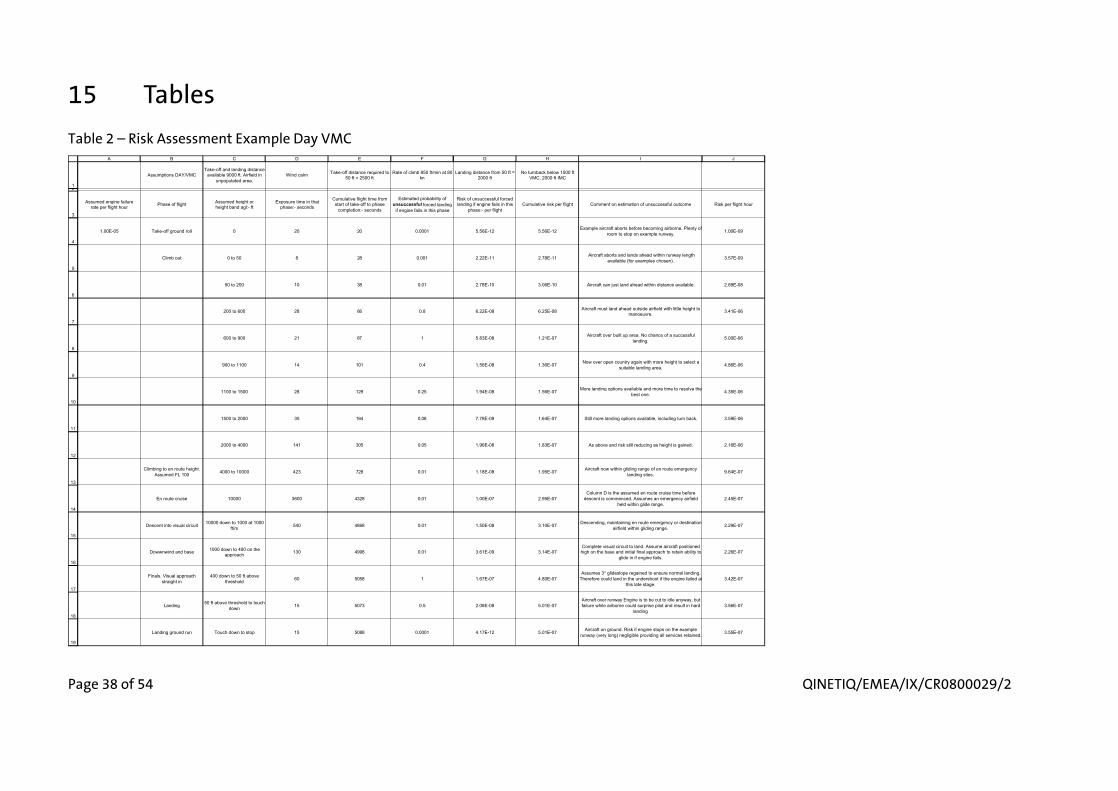
Page 38 of 54 QINETIQ/EMEA/IX/CR0800029/2
15 TablesTable 2 – Risk Assessment Example Day VMC
12
3
4
5
6
7
8
9
10
11
12
13
14
15
16
17
18
19
A B C D E F G H I J
Assumptions DAY/VMCTake-off and landing distance
available 9000 ft. Airfield inunpopulated area.
Wind calm Take-off distance required to 50 ft = 2500 ft
Rate of climb 850 ft/min at 80 kn
Landing distance from 50 ft = 2000 ft
No turnback below 1500 ft VMC, 2000 ft IMC
Assumed engine failure rate per flight hour Phase of flight Assumed height or
height band agl:- ftExposure time in that
phase:- seconds
Cumulative flight time from start of take-off to phase
completion:- seconds
Estimated probability of unsuccessful forced landing
if engine fails in this phase
Risk of unsuccessful forced landing if engine fails in this
phase:- per flightCumulative risk per flight Comment on estimation of unsuccessful outcome Risk per flight hour
1.00E-05 Take-off ground roll 0 20 20 0.0001 5.56E-12 5.56E-12 Example aircraft aborts before becoming airborne. Plenty of room to stop on example runway. 1.00E-09
Climb out 0 to 50 8 28 0.001 2.22E-11 2.78E-11 Aircraft aborts and lands ahead within runway length available (for examples chosen). 3.57E-09
50 to 200 10 38 0.01 2.78E-10 3.06E-10 Aircraft can just land ahead within distance available. 2.89E-08
200 to 600 28 66 0.8 6.22E-08 6.25E-08 Aircraft must land ahead outside airfield with little height to manoeuvre. 3.41E-06
600 to 900 21 87 1 5.83E-08 1.21E-07 Aircraft over built up area. No chance of a successful landing. 5.00E-06
900 to 1100 14 101 0.4 1.56E-08 1.36E-07 Now over open country again with more height to select a suitable landing area. 4.86E-06
1100 to 1500 28 129 0.25 1.94E-08 1.56E-07 More landing options available and more time to resolve the best one. 4.35E-06
1500 to 2000 35 164 0.08 7.78E-09 1.64E-07 Still more landing options available, including turn back. 3.59E-06
2000 to 4000 141 305 0.05 1.96E-08 1.83E-07 As above and risk still reducing as height is gained. 2.16E-06
Climbing to en route height. Assumed FL 100 4000 to 10000 423 728 0.01 1.18E-08 1.95E-07 Aircraft now within gliding range of en route emergency
landing sites. 9.64E-07
En route cruise 10000 3600 4328 0.01 1.00E-07 2.95E-07Column D is the assumed en route cruise time before
descent is commenced. Assumes an emergency airfield held within glide range.
2.45E-07
Descent into visual circuit 10000 down to 1000 at 1000 ft/m 540 4868 0.01 1.50E-08 3.10E-07 Descending, maintaining en route emergency or destination
airfield within gliding range. 2.29E-07
Dowwnwind and base 1000 down to 400 on the approach 130 4998 0.01 3.61E-09 3.14E-07
Complete visual circuit to land. Assume aircraft positioned high on the base and initial final approach to retain ability to
glide in if engine fails.2.26E-07
Finals. Visual approach straight in
400 down to 50 ft above threshold 60 5058 1 1.67E-07 4.80E-07
Assumes 3° glideslope regained to ensure normal landing. Therefore could land in the undershoot if the engine failed at
this late stage.3.42E-07
Landing 50 ft above threshold to touch down 15 5073 0.5 2.08E-08 5.01E-07
Aircraft over runway Engine is to be cut to idle anyway, but failure while airborne could surprise pilot and result in hard
landing3.56E-07
Landing ground run Touch down to stop 15 5088 0.0001 4.17E-12 5.01E-07 Aircraft on ground. Risk if engine stops on the example runway (very long) negligible providing all services retained. 3.55E-07
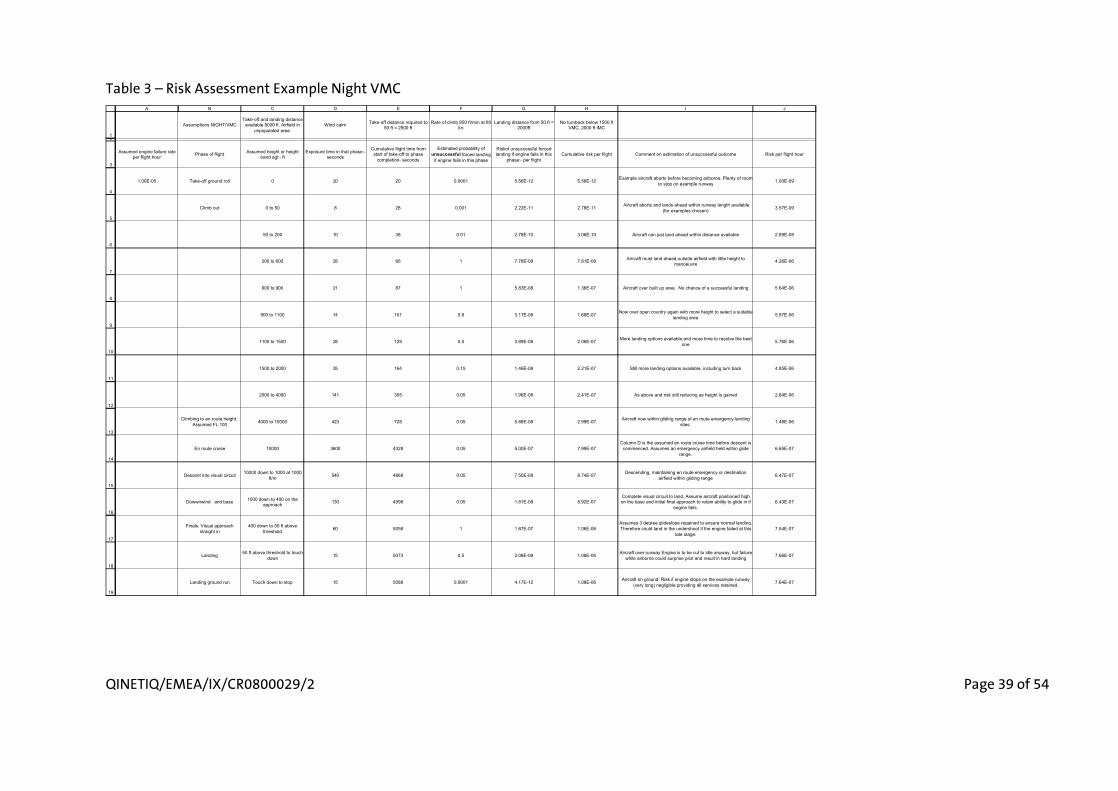
QINETIQ/EMEA/IX/CR0800029/2 Page 39 of 54
Table 3 – Risk Assessment Example Night VMC
12
3
4
5
6
7
8
9
10
11
12
13
14
15
16
17
18
19
A B C D E F G H I J
Assumptions NIGHT/VMCTake-off and landing distance
available 9000 ft. Airfield in unpopulated area.
Wind calm Take-off distance required to 50 ft = 2500 ft
Rate of climb 850 ft/min at 80 kn
Landing distance from 50 ft = 2000ft
No turnback below 1500 ft VMC, 2000 ft IMC
Assumed engine failure rate per flight hour Phase of flight Assumed height or height
band agl:- ftExposure time in that phase:-
seconds
Cumulative flight time from start of take-off to phase
completion- seconds
Estimated probability of unsuccessful forced landing
if engine fails in this phase
Riskof unsuccessful forced landing if engine fails in this
phase:- per flightCumulative risk per flight Comment on estimation of unsuccessful outcome Risk per flight hour
1.00E-05 Take-off ground roll 0 20 20 0.0001 5.56E-12 5.56E-12 Example aircraft aborts before becoming airborne. Plenty of room to stop on example runway 1.00E-09
Climb out 0 to 50 8 28 0.001 2.22E-11 2.78E-11 Aircraft aborts and lands ahead within runway length available (for examples chosen) 3.57E-09
50 to 200 10 38 0.01 2.78E-10 3.06E-10 Aircraft can just land ahead within distance available 2.89E-08
200 to 600 28 66 1 7.78E-08 7.81E-08 Aircraft must land ahead outside airfield with little height to manoeuvre 4.26E-06
600 to 900 21 87 1 5.83E-08 1.36E-07 Aircraft over built up area. No chance of a successful landing 5.64E-06
900 to 1100 14 101 0.8 3.11E-08 1.68E-07 Now over open country again with more height to select a suitable landing area 5.97E-06
1100 to 1500 28 129 0.5 3.89E-08 2.06E-07 More landing options available and more time to resolve the best one 5.76E-06
1500 to 2000 35 164 0.15 1.46E-08 2.21E-07 Still more landing options available, including turn back 4.85E-06
2000 to 4000 141 305 0.05 1.96E-08 2.41E-07 As above and risk still reducing as height is gained 2.84E-06
Climbing to en route height . Assumed FL 100 4000 to 10000 423 728 0.05 5.88E-08 2.99E-07 Aircraft now within gliding range of en route emergency landing
sites. 1.48E-06
En route cruise 10000 3600 4328 0.05 5.00E-07 7.99E-07Column D is the assumed en route cruise time before descent is commenced. Assumes an emergency airfield held within glide
range.6.65E-07
Descent into visual circuit 10000 down to 1000 at 1000 ft/m 540 4868 0.05 7.50E-08 8.74E-07 Descending, maintaining en route emergency or destination
airfield within gliding range 6.47E-07
Dowwnwind and base 1000 down to 400 on the approach 130 4998 0.05 1.81E-08 8.92E-07
Complete visual circuit to land. Assume aircraft positioned high on the base and initial final approach to retain ability to glide in if
engine fails.6.43E-07
Finals. Visual approach straight in
400 down to 50 ft above threshold 60 5058 1 1.67E-07 1.06E-06
Assumes 3 degree glideslope regained to ensure normal landing. Therefore could land in the undershoot if the engine failed at this
late stage.7.54E-07
Landing 50 ft above threshold to touch down 15 5073 0.5 2.08E-08 1.08E-06 Aircraft over runway Engine is to be cut to idle anyway, but failure
while airborne could surprise pilot and result in hard landing 7.66E-07
Landing ground run Touch down to stop 15 5088 0.0001 4.17E-12 1.08E-06 Aircraft on ground. Risk if engine stops on the example runway (very long) negligible providing all services retained. 7.64E-07

Page 40 of 54 QINETIQ/EMEA/IX/CR0800029/2
Table 4 – Risk Assessment Example IMC Visibility 1200 m Ceiling 500 ft
12
3
4
5
6
7
8
9
10
11
12
13
14
15
16
17
18
19
20
A B C D E F G H I J
Assumptions NIGHT/IMC500 ft ceiling 1200 m vis
Take-off and landing distance available 9000 ft. Airfield in
unpopulated areaWind calm Take-off distance required
to 50 ft = 2500 ftRate of climb
850 ft/min at 80 knLanding distance
from 50 ft = 2000ft No turnback below 1500 ft VMC, 2000 ft IMC
Assumed engine failure rate per flight hour Phase of flight Assumed height or height
band agl:- ftExposure time in that phase:-
seconds
Cumulative flight time from start of take-off to phase
completion- seconds
Estimated probability of unsuccessful forced landing
if engine fails in this phase
Riskof unsuccessful forced landing if engine fails in this
phase:- per flightCumulative risk per flight Comment on estimation of unsuccessful outcome Risk per flight hour
1.00E-05 Take-off ground roll 0 20 20 0.0001 5.56E-12 5.56E-12 Example aircraft aborts before becoming airborne. Plenty of room to stop on example runway 1.00E-09
Climb out 0 to 50 8 28 0.001 2.22E-11 2.78E-11 Aircraft aborts and lands ahead within runway length available (for examples chosen) 3.57E-09
50 to 200 10 38 0.01 2.78E-10 3.06E-10 Aircraft can just land ahead within distance available 2.89E-08
200 to 600 28 66 1 7.78E-08 7.81E-08 Aircraft must land ahead outside airfield with little height to manoeuvre 4.26E-06
600 to 900 21 87 1 5.83E-08 1.36E-07 Aircraft over built up area. No chance of a successful landing and in cloud. 5.64E-06
900 to 1100 14 101 1 3.89E-08 1.75E-07 Now over open country again but in cloud with no visual cues to select a favourable landing area. 6.25E-06
1100 to 1500 28 129 1 7.78E-08 2.53E-07 Still in cloud with no visual cues to select a favourable landing area and below turn back height 7.06E-06
1500 to 2000 35 164 1 9.72E-08 3.50E-07 As above, risk still at highest level 7.69E-06
2000 to 2500 35 199 1 9.72E-08 4.48E-07 As above 8.10E-06
2500 to 4000 106 305 0.5 1.47E-07 5.95E-07 Now in a position to turn back 7.02E-06
Climbing to en route height . Assumed FL 100 4000 to 10000 423 728 0.05 5.88E-08 6.54E-07 Aircraft now within gliding range of en route emergency
landing sites for IMC approach 3.23E-06
En route cruise 10000 3600 4328 0.05 5.00E-07 1.15E-06Column D is the assumed en route cruise time before
descent is commenced. Assumes an emergency airfield held within glide range.
9.59E-07
Descent to initial approach fix for IFR approach
10000 down to 4000 at 1000 ft/m 360 4688 0.05 5.00E-08 1.20E-06 Descending, maintaining en route emergency or destination
airfield within gliding range 9.24E-07
Aircraft must descend below a glide approach capability, to set up for a normal powered
landing at 3° app.from 1000 ft
4000 down to 1000ft on the approach 133 4821 0.5 1.85E-07 1.39E-06
Aircraft descends below the height needed to maintain a glide approach that will reach the airfield. Therefore could
land short of airfield if engine failed. 50% risk of unsuccessful landing assumed.
1.04E-06
Aircraft descends on 3° approach path.
1000 ft down to 50 ft on approach 134 4955 1 3.72E-07 1.76E-06
Assumes 3° glideslope regained to ensure normal landing. Therefore could land in the undershoot if the engine failed at this late stage. 100% risk of unsuccessful landing assumed
1.28E-06
Landing 50 ft above threshold to touch down 15 4970 0.5 2.08E-08 1.78E-06
Aircraft over runway Engine is to be cut to idle anyway, but failure while airborne could surprise pilot and result in hard
landing1.29E-06
Landing ground run Touch down to stop 15 4985 0.0001 4.17E-12 1.78E-06 Aircraft on ground. Risk if engine stops on the example runway (very long) negligible providing all services retained. 1.29E-06

QINETIQ/EMEA/IX/CR0800029/2 Page 41 of 54
16 FiguresFigure 1 – Risk Profile Example Day VMC
0
1000
2000
3000
4000
5000
6000
7000
8000
9000
-100 -80 -60 -40 -20 0 20 40 60 80 100
Risk (%)
Hei
gh
t at
En
gin
e F
ailu
re (
ft a
gl)
DEPARTURE EGXXAIRFIELDDEPARTURE 23RUNWAY
DESTINATION EGYYAIRFIELDDESTINATION 18RUNWAY
DURING DESCENT AIRCRAFTMAINTAINED WITHIN GLIDINGDISTANCE OF EN-ROUTE ORDESTINATION AIRFIELDS99% PROBABILITY OFSUCCESSFUL FORCED LANDING
TURNBACK OPTIONAVAILABLE
AIRCRAFT POSITIONED ATHIGH OR LOW KEY POINTSIN VISUAL CIRCUIT SO THATGLIDE APPROACH ALWAYSPOSSIBLE
AIRCRAFT POSITIONED FORNORMAL 3° APPROACHIF ENGINE FAILS WILLLAND SHORT OF AIRFIELDINTO WATER
INCREASING HEIGHTMORE SCOPE FORSUCCESSFULLANDING AHEAD
OFF AIRFIELD LANDINGOPEN COUNTRY BUT LITTLEHEIGHT TO MANOUEVRE
CAN LAND AHEAD ON RUNWAY
CLIMB OUT PATH OVERINDUSTRIAL ESTATE,NO CHANCE OFSUCCESSFUL LANDING
TAKE OFF, CLIMB, AND CRUISE PHASES CRUISE, DESCENT AND LANDING PHASES
NOW WITHIN GLIDING RANGEOF EMERGENCY EN-ROUTEAIRFIELDS, 99% PROBABLITYOF SUCCESSFUL FORCED LANDING

Page 42 of 54 QINETIQ/EMEA/IX/CR0800029/2
Figure 2 – Possible IFR Approach
0
1000
2000
3000
4000
5000
6000
-5000 0 5000 10000 15000 20000 25000 30000 35000 40000 45000 50000 55000 60000
Distance from threshold (ft)
Heig
ht a
bove
thre
shol
d (ft
)
AIRCRAFT CANNOTGLIDE TO THE RUNWAYFROM THIS POINTONWARDS
AIRCRAFT HAS THEABILITY TO GLIDETO THE RUNWAY
FULL FLAPGLIDE ANGLE = 9.5°
CLEANGLIDE ANGLE = 6°
NORMAL APPROACHANGLE = 3°
1000 ft
NORMAL POWER ON STABILISED APPROACHAT 3° FROM THIS POINT
4000 ft INITIALAPPROACH FIX

QINETIQ/EMEA/IX/CR0800029/2 Page 43 of 54
Figure 3 – Risk Profile Example Night VMC
0
1000
2000
3000
4000
5000
6000
7000
8000
9000
-100 -80 -60 -40 -20 0 20 40 60 80 100
Risk (%)
Hei
gh
t at
En
gin
e F
ailu
re (
ft a
gl)
DEPARTURE EGXXAIRFIELDDEPARTURE 23RUNWAY
DESTINATION EGYYAIRFIELDDESTINATION 18RUNWAY
DURING DESCENT AIRCRAFTMAINTAINED WITHIN GLIDINGDISTANCE OF EN-ROUTE ORDESTINATION AIRFIELDS95% PROBABILITY OFSUCCESSFUL FORCED LANDING
NOW WITHIN GLIDING RANGEOF EMERGENCY EN-ROUTEAIRFIELDS, 95% PROBABLITYOF SUCCESSFUL FORCED LANDING
TURNBACK OPTIONAVAILABLE
AIRCRAFT POSITIONED FORNORMAL 3° APPROACHIF ENGINE FAILS WILLLAND SHORT OF AIRFIELD
OFF AIRFIELD LANDINGLIMITED HEIGHT ANDVISION TO IDENTIFY ANDREACH LANDING AREA OPEN COUNTRY
CAN LAND AHEAD ON RUNWAY
TAKE OFF, CLIMB, AND CRUISE PHASES CRUISE, DESCENT AND LANDING PHASES
AIRCRAFT POSITIONED ATHIGH OR LOW KEY POINTSIN VISUAL CIRCUIT SO THATGLIDE APPROACH ALWAYSPOSSIBLEINCREASING HEIGHT MORE
CHANCE OF SUCCESSFULLANDING AHEAD

Page 44 of 54 QINETIQ/EMEA/IX/CR0800029/2
Figure 4 – Risk Profile Example Night IMC
0
1000
2000
3000
4000
5000
6000
7000
8000
9000
-100 -80 -60 -40 -20 0 20 40 60 80 100
Risk (%)
Hei
gh
t at
En
gin
e F
ailu
re (
ft a
gl)
DEPARTURE EGXXAIRFIELDDEPARTURE 23RUNWAY
DESTINATION EGYYAIRFIELDDESTINATION 18RUNWAY
DURING DESCENT AIRCRAFTMAINTAINED WITHIN GLIDINGDISTANCE OF EN-ROUTE ORDESTINATION AIRFIELDS95% PROBABILITY OFSUCCESSFUL FORCED LANDING
TURNBACK OPTIONAVAILABLE
AIRCRAFT POSITIONED FORNORMAL 3° APPROACHIF ENGINE FAILS WILLLAND SHORT OF AIRFIELD
OFF AIRFIELD LANDINGOPEN COUNTRY
CAN LAND AHEAD ON RUNWAY
TAKE OFF, CLIMB, AND CRUISE PHASES CRUISE, DESCENT AND LANDING PHASES
NOW WITHIN GLIDING RANGEOF EMERGENCY EN-ROUTEAIRFIELDS, 95% PROBABLITYOF SUCCESSFUL FORCED LANDING
AIRCRAFT NOW BELOWHEIGHT NEEDED TO GLIDETO THE AIRFIELD

QINETIQ/EMEA/IX/CR0800029/2 Page 45 of 54
A EASA Comments on Issue 1 and QinetiQ responseA.1 This Appendix contains EASA comments on Issue 1 of this report together with QinetiQ
response.
A.2 EASA Comments 1, 2 and 3
A.2.1 Comment 1: Instead of HSE guidelines and figures which we are not able to meet by far, base the concept on the old JAA criteria (loss of power rate and fatality accident rate - total and following loss of power).
A.2.2 Comment 2: Use existing twin pistons and turboprop twins safety records as benchmarks for SE-IMC aircraft.
A.2.3 Comment 3: Recommend to the Agency the target position for SE-IMC aircraft against these two benchmarks.
A.3 QinetiQ response to EASA Comment 1, 2 and 3
A.3.1 Comments 1, 2, and 3 suggested that the existing twin turbo prop and piston twins should be the benchmark when establishing the safety targets for SET, and that the HSE guidelines should be kept only for reference.
A.3.2 These comments are best answered together rather than individually. Firstly the QinetiQ assumption was that it had already been accepted in the JAA study that it was not practicable for SET aircraft to attain the safety standards currently achieved by the major western carriers using large multi engine aircraft. (risk of a fatal accident currently <0.5 x 10⁻⁶ per flight hour). Hence the NPA OPS 29 Rev 2 proposal, based on the “all causes” fatal accident rate not being more frequent than 5 x 10⁻⁶ per flight hour, appeared to accept that SET operations would be roughly one order more risky than for a flight with a major carrier in a large aircraft.
A.3.3 QinetiQ was also asked not to take the JAA proposals as read, but to independently comment on what the numerical values might be. This request led the QinetiQ Working Group to look at safety from the unusual perspective (for aviation) of Health and Safety criteria and the occupational risk to the crew. The result was that 4 x 10⁻⁶ per flight hour was recommended rather than 5 x 10⁻⁶ as the “all causes” target for the fatal accident rate.
A.3.4 From Comment 2, it now appears that EASA wishes to revert to using the twin piston and turbo prop twins as the benchmark. Before doing so it is suggested that Figure A.1 should be studied. This consolidates the data in paragraph 2.1 of the main report and correlates the risk of a fatal accident per flight hour, with the HSE criterion of annual risk of death due to an individual’s occupation.
A.3.5 The figure is drawn as a log/log plot. The X axis shows the annual risk of death for an individual crew member, ranging from 1 in 100 to 1 in 10 000, with the HSE criterion (that the occupational risk of death should be no more frequent than 1 in 1000 per annum) shown as a vertical line. The Y axis represents the risk of a fatal accident per flight hour. The sloping lines on the graph show the relation between the two ways of expressing risk, for various assumed values of individual crew member flying hours per year, namely 500 (the value suggested as appropriate for this type of operation and which is discussed further

Page 46 of 54 QINETIQ/EMEA/IX/CR0800029/2
later on), 700 and 900 hours per year. The latter is the around the maximum permitted by various airworthiness authorities.
A.3.6 On this figure is shown the safety of the various classes of operation discussed in paragraph 2.1 of the main report. At bottom left is the safest class of operation, namely flying with a major carrier, with a per flight hour accident rate assumed as 0.5 x 10⁻⁶. A pilot flying 900 hours per year will have a 1 in 2222 chance of death, which clearly meets the HSE guideline.
A.3.7 Moving right across the graph, the next point shows the safety of all US commercial pilots, giving an annual chance of death of 1 in 1250. This also meets the HSE guidelines, but the flight hours have been assumed as spanning the range from 500 to 900 because of the different types of operation encompassed in this group.
A.3.8 On the extreme right hand side of the graph is shown the position with current twin engine types, using the spread of values of fatal accidents per flight hour, ranging from 4.9 x 10⁻⁶
(Paragraph 2.2.1 of the main report) to 6.2 x 10⁻⁶ (Paragraph 2.2.4). Also shown is the suggested target of the annual risk of death not exceeding 1 in 500 for SET operations, assuming an average of 500 hours per year exposure and where the fatal accident rate is 4 x 10⁻⁶ per flight hour. If this criterion is adopted, then the move to SET would be accompanied by a small but worthwhile increase in safety over the range of possible aircrew annual flight hours, although still falling short of the HSE target. If the original JAA proposal was adopted, (fatal accident rate 5 x 10⁻⁶ per flight hour) the annual risk of death would be 1 in 400 and there would be no clear improvement over current twin engine equipment.
A.3.9 To answer the question why the WG accepted a more risky value than the HSE target of 1 in 1000, as the normally accepted occupational risk level, it is best to quote directly from the HSE document cited in [3].
“…we can say that broadly a risk of death around 1 in 1000 per annum is the most that is ordinarily accepted by substantial groups of workers in any industry in the UK, with that level being exceeded only by fishermen and relatively small sub groups such as helicopter pilots, divers and demolition workers. It seems therefore reasonable to adopt a risk of death of around 1 in 1000 as the dividing line between what is just about tolerable as a risk to be accepted by any substantial category for any large part of a working life, and what is unacceptable for any but fairly exceptional groups”.
A.3.10 From this explanation, while the regulatory authority should be aiming at 1 in 1000, there is latitude to compromise, as in the precedent set by the quoted example of helicopter pilots. The intent of bettering the current twin engine levels of safety, demonstrates that there is a clear commitment to improving safety, but within the constraints of what is reasonably possible.
A.3.11 To summarise; by retaining a target fatal accident rate for SET no more frequent than 4 x 10⁻⁶ per flight hour from all causes there will be a small improvement in flight safety over that currently achieved by twin engine aircraft in comparable categories, even though the HSE guideline is not reached. Therefore QinetiQ still recommends this value as a pragmatic compromise between the ideal and the attainable.

QINETIQ/EMEA/IX/CR0800029/2 Page 47 of 54
A.4 EASA Comment 4
A.4.1 Keep the HSE figures in the report for reference but better explain why we can afford for SE-IMC aircraft to achieve only half of the HSE threshold (1 in 500 instead of 1 in 1000) compare to 1 in 2222 for large passenger carrying aircraft. Provide a link between the crew and passenger fatality rates, reflect the risk for the co-pilot and estimate the risk to the passengers.
A.5 QinetiQ response to EASA Comment 4
A.5.1 Comment 4 asked for a link between crew and passenger fatality rates. In the context of a target fatal accident rate (all causes) being established, then the amount of flying done by any individual determines his risk of death. As stated previously, for a crew member (be he pilot, co-pilot or flight attendant), the fatal accident rate multiplied by an individual’s annual flight hours give that risk. It is unlikely that any individual passenger would fly the same number of hours per year as a crew member, but if he did then he would run the same chance of death.
A.6 EASA Comment 5
A.6.1 Check and if necessary better explain all the assumptions (magic figures) used in the report to substantiate introduction of the SE-IMC operations. Namely assure that the origin of the figures is always provided together with the way how they were derived. When a key figure is used for SE–IMC concept, explain why it should be considered acceptable and which benchmark was used to substantiate this. Namely the following:
a. Why 500 flying hours (Paragraph 2.1.5) for commercial SET aircraft pilot is a realistic estimate? Can we better support the figure by referring to some literature/study?
b. How can you better justify your conclusion that 33 % proportion (Paragraph 2.2.8) of engine failure cause of fatal accidents (against all the causes) can be maintained when for large aircraft it is just 2.5%? Why situation in large airplanes sector is not applicable here and why it cannot be simply scaled down? Also, 33% number was based on piston and turbine twins records. If the turbine engines are more reliable, consider a possibility to reflect it in the proportion proposed for SE-IMC. This should be in line with item 3 and the recommended target position for SE-IMC relative to twin pistons and twin turboprops. If there is a lack of data to calculate the proportion for turbine engines, at least make a remark about this in the report.
c. For paragraph 2.3.5 have you managed to obtain the flight hours for the individual aircraft categories given in Table 1?
d. In paragraph 4.2.3 and paragraph 4.2.4 explain how you arrived to the figures 1 in 100 and 1 in 20 (or the factor of 5).
e. Justify the figures in paragraph 4.2.6. On which basis were they selected?
A.6.2 QinetiQ response to EASA Comment 5
A.6.3 Question a: Documented support for the estimate was obtained from a survey carried out by the Transportation Safety Board of Canada in 1993. It conducted a survey of pilots working in small commercial operations. Just over 2000 pilots out of an estimated population of 4000 replied. The mean yearly flying hours of all the respondents was 461. (Flight Safety Foundation, Flight Safety Digest May 1993).

Page 48 of 54 QINETIQ/EMEA/IX/CR0800029/2
A.6.4 Question b: The report did not set out to show that SET operations were too unsafe to be considered, which would be the consequence of directly “scaling” the large aircraft risk budget. For instance, if the overall target fatal accident rate was to be no more frequent than 4 x 10⁻⁶ per flight hour as recommended, then to allow only 2.5% of that for engine failure would mean a fatal accident rate following engine failure no more frequent than 0.1 x 10⁻⁶ per flight hour. As shown in the risk assessment methodology of the report, on any rational basis use of that target would probably rule out even a day/VMC clearance, which is already permitted. Therefore, as explained in the report, the approach taken consisted of looking at the historic ratio of fatal accident rates following power loss to the overall fatal accident rate for twin engine aircraft (33%) as a means of setting a risk target for fatal accidents following engine failure for the SET. Once again, this came down to seeking some safety increase relative to that currently achieved. The accident records for twin piston and turbine aircraft combined were taken to widen the sample size, on the basis that once one engine had failed, the outcome was not dependent on whether or not the remaining operating engine was turbine or piston.
A.6.5 Question c: The answer is no because, as stated in paragraph 2.3.6 of the main report, Table 1 was based on very recent incident/accident data for February 2006 to February 2007. The argument was based on the fact that for the Single Engine Piston category it was reasonable to use the historical hours flown by this category (760 000) to obtain the accident rates, because analysis of usage during the preceding decade had shown little significant change. It was felt that a similar projection for the multi engine aircraft could be misleading because of the smaller aircraft numbers involved, and the fact that CAA data had not yet been collated for the 2006/2007 period. Hence use was made of the 5 year period of 2000 to 2004 inclusive as giving a better substantiated value of twin turbine fleet hours (80 590). While not relevant to the argument presented, which concerned turbine reliability, the corresponding twin piston usage over the same period was 443 012 hours.
A.6.6 Question d: The estimate success rates for a forced landing were a professional judgement from an ex-RAF Qualified Flying Instructor with considerable experience of teaching practice forced landings in high performance training aircraft. While the values might, at first glance, be considered optimistic, the associated caveats have to be considered. Firstly, the values quoted only apply to engine failure at a point from which the aircraft is capable of reaching a suitable landing site. Therefore the risk arises from pilot misjudgement of energy management. Secondly, the estimated success rates assume that both horizontal and vertical navigation aids will assist the pilot in managing the energy correctly. The adequacy of the aids provided must be assessed when a type is approved for SE IMC (Paragraph 12.10 of the main report). Thirdly, the estimated success rates assume that adequate initial and continuation training is provided.
A.6.7 Question e: The angles given are purely hypothetical, based on values that might be expected from an aircraft with an approach speed of around 80 knots CAS. It is envisaged that when an SE IMC clearance is required for a specific type, the glide performance in different configurations and at different speeds will be available to determine the approach profiles that can be flown.
A.7 EASA Comment 6
A.7.1 Specify in the training requirements (Chapter 7) that, in the case minimum 2 crew operations are required, the training must focus on “multi-crew” features of the crew training, i.e. on communication and distribution of the tasks and cooperation between both pilots in emergency situations, namely after loss of power. In the Conclusions &

QINETIQ/EMEA/IX/CR0800029/2 Page 49 of 54
Recommendations specify that the assumption is for a properly constituted and trained crew of 2 pilots supported by appropriate Standard Operating Procedures (SOP).
A.8 QinetiQ response to EASA Comment 6
A.8.1 Comment 7 is agreed and at Issue 2 of the report a new paragraph 7.4 will be added, with complementary material at paragraph 11.15 (Conclusions) and paragraph 12.11 (Recommendations).

Page 50 of 54 QINETIQ/EMEA/IX/CR0800029/2
Figure A.1 – Annual risk of death
1.0E-07
1.0E-06
1.0E-05
0.0001 0.001 0.01
Annual risk of death for individual crew member
Ris
k of
fata
l acc
iden
t (pe
r flig
ht h
our)
Suggested SET target
HSE target
Pilots flying for major airlines
All USA commercial pilots
Australian data - current twins <5700 kg
United Kingdom data - current twins <5700 kg
1 in 1000 1 in 100
500 annual flying hours700 annual flying hours900 annual flying hours
1 in 10000

QINETIQ/EMEA/IX/CR0800029/2 Page 51 of 54
Initial distribution list
External
Jan Novák, EASA, Rulemaking Directorate
QinetiQ
Information Resources
File

Page 52 of 54 QINETIQ/EMEA/IX/CR0800029/2
Blank page

QINETIQ/EMEA/IX/CR0800029/2 Page 53 of 54
Report documentation page
Originator's Report Number QINETIQ/EMEA/IX/CR0800029/2
Originator's Name and Location
John Bradley
Systems Evaluation Services
QinetiQ, Boscombe Down
Wiltshire SP4 OJF
Customer Contract Number and Period Covered EASA-2006-C46
Customer Sponsor's Post/Name and Location Jan Novák, EASA Rulemaking Directorate
Report Protective Marking and any other markings
Date of issue Pagination No. of references
UNMARKED 15th October 2007 54 + Covers 16
Report Title
Risk Assessment for European Public Transport Operations using Single Engine Turbine Aircraft at Night and in IMC
Title Protective Marking UNMARKED
Authors John Bradley
AbstractThe objectives of this report were to conduct a full and objective risk assessment of operating single engine turbo-prop aircraft within Europe at night and in IMC (SE-IMC) for Public Transport Operations. Risk mitigations were to be identified and comparisons made with the risks incurred when operating light twin engine aircraft in similar conditions. The work was undertaken on behalf of the European Aviation Safety Agency (EASA).The report suggested risk targets for fatal accident rates from all causes should be no greater than 4.0 x 10⁻⁶ per flight hour, and for fatal accidents following engine failure no greater than 1.3 x 10⁻⁶ per flight hour. If these targets were met, there would be an improvement in safety relative to the record for light twin engine aircraft.Historical statistical evidence showed that, overall, the risk targets could be met, but the evidence was too sparse to predict the increase in risk arising from operation at night and in IMC. Therefore a risk assessment methodology was developed that allowed a rational assessment of the risks, but it was necessary to make this assessment on a case by case basis.Using reasonable assumptions, and assuming that the risk mitigation measures already proposed by the Joint Airworthiness Authority (prior to the formation of EASA) were adopted, it was possible to show that the risk target for a fatal accident following engine failure could be met at night and in IMC. However, additional mitigation measures were recommended, and it assumed that the engine failure rate could be shown as more remote than 1 in 100 000 hours.It was concluded that there should be no blanket prohibition on SE-IMC, but an applicant would have to undertake a risk assessment for each of the routes for which an approval was sought and this would include an explanation of how it was proposed to integrate the single engine aircraft in to the air traffic system while mitigating the risks of an engine failure.If approved, initial operational experience should be recorded to build statistical evidence to support expansion of this type of operation.
Abstract Protective Marking: UNMARKED
This form meets DRIC-SPEC 1000 issue 7

Page 54 of 54 QINETIQ/EMEA/IX/CR0800029/2
Blank page