Embed Size (px)
Citation preview

Installers please note these InstructIons are to be left wIth the user
2180531A September 2006
Installation instructions
METISRiser rail kit
Part 2: Kit

ConTEnTS Page
General installation notes 1
Main components 2
Installation options 3 – 4
Installation Option 1: Rear entry supply 5 – 8
Components 5
Fitting the riser rail 6 – 7
Fitting through the ceiling — general 8
Installation Option 2: Falling supply — through the ceiling riser rail (short) 9 – 11
Components 9
Fitting the through ceiling riser rail 10 – 11
Installation Option 3: Falling supply — through the ceiling riser rail (long) 12 – 15
Components 12
Fitting the through ceiling riser rail 13 – 15
Plumbing connections 16 – 18
Option 1 — Fitting the bulkhead 16 – 17
Options 2 & 3 — Fitting the outlet connector 17 – 18
Adjusting the showerhead 19
Cleaning the showerhead 20
Spare parts 21
Guarantee, service policy, etc. rear cover
Part 2: Kit

�
Part 2: Kit
8.Fitthecontrolpaneltothewall
Install the remote control panel wall mounting bracket within the showering area. Fit the control panel onto the bracket.
9.Operation
Operate the shower and set preferred flow settings.
The following notes are given as the suggested steps for installing the Satellites mixer shower and remote control:
1.Sitesurvey
Determine the position of all parts of the shower (kit, mixing unit and control) before starting the installation.
2.Fitthemixingunit
3.Installtheappropriateriserrail
Having determined the position of the mixing unit, decide on which riser rail kit to use. Option 1 is for rear supply; Option 2 and Option 3 are for a falling supply.
4.Installthepipeworkandplumbing
Run the pipework from the mixing unit to the chosen outlet. The rear supply will terminate at the bulkhead position, while a falling supply will terminate in the loft at the top of the riser rail. Connect the inlet pipework, the outlet pipework and then the outlet fittings.
5.Electricalconnections
Connect the mixing unit to the electrical supplies.
6.Registertheremotecontrolpanel
Register the control panel to the mixing unit.
7.Commissiontheunit
Commission the shower and select the desired feature settings.
GEnERal InSTallaTIon noTES
AvideodetailingtheinstallationoftheSatellitesmixershowercanbeseenat
www.tritonshowers.co.uk.
ADVDisalsoavailableonrequest.ContacttheBrochurerequestlinefor
detailson
024 7632 4460
To check the product suitability for commercial and multiple installations, please contact Triton’s specification advisory service before installation.
Telephone: 0870 067 3767
Facsimile: 0870 067 3334
E mail: [email protected]

2
Part 2: Kit
Fig.1MaIn CoMPonEnTS
Riserrailkitcontents(Fig.1)
1. Showerhead holder
2. Bridging wall bracket (lug on inside)
3. Guide bracket (no lugs inside)
4. Bottom bracket
5. Bottom bracket (through ceiling option)
6. Bracket trim ring (3 off)
7. Bracket spacer (3 off)
8. Heated water pipe hose connector
9. Water outlet fitting retaining clip
10. Ceiling trim
11. Riser rail end trim
12. Riser rail – 40 mm
13. Riser rail – 700 mm
14. Riser rail – 940 mm
15. Hose retainer
16. Flexible hose
17. 15 mm push-fit elbow
18. Outlet bulkhead
19. All thread fitting
20. 5 position rub clean showerhead
21. Fixing screws and wall plugs (not shown)
Instructions, guarantee, template etc.
1
2
3
4
5
6
6
6
7
7
7
89
10
11
12
13
14
15
1617
18
19 20

�
Part 2: Kit
Bridging bracket
Showerhead holder
Control panel
Bottom bracket
Bulkhead
Rear entry supply Fig.2InSTallaTIon oPTIonS
Rear entry supply — option �The control panel is installed onto a tiled wall. The mixing unit is behind an adjoining wall with heated water pipe (supplied in the mixing unit) running to the bulkhead (Fig.2).
Falling supply — options 2 & �Here the mixing unit is installed in the loft with the heated water pipe (supplied in the mixing unit) running down the inside of the riser rail. Water outlet at the bottom of the riser rail.
Fig.3 shows the shorter version using the 940 mm riser rail passing through the guide bracket.
Fig.4 shows the long version using three brackets and both riser rail sections. This uses the 700 mm rail connecting to the bridging bracket with the 940 mm rail cut to length.

�
Part 2: Kit
Guide bracket
Showerhead holder
Control unit
Bottom bracket
Ceiling trim
Hot water pipe
940 mm rail
Guide bracket
Showerhead holder
Control panel
Bottom bracket
Bridging bracket
Ceiling trim
Hot water pipe
Fig.3Falling supply fitting (short) Falling supply fitting (long) Fig.4

�
Part 2: Kit
Components
Thisoptionisforinstallingtheriserrailforusewitharearentrysupply.
Fig.5 shows the parts required to install the stand-alone riser rail kit. Note that either riser rail section can be used.
1. 40 mm riser rail section
2. Bridging bracket
3. 700 mm or 940 mm riser rail section
4. Showerhead holder
5. Hose retainer
6. Bottom bracket (blanked off)
7. Bracket end trim (2 off)
8. Riser rail end trim
Bulkhead assembly
Screws and fittings
InSTallaTIon oPTIon �: REaR SuPPly —ThRouGh ThE Wall RISER RaIl
Fig.5
1
2
3
4
5
6
7
7
8
�
Part 2: Kit
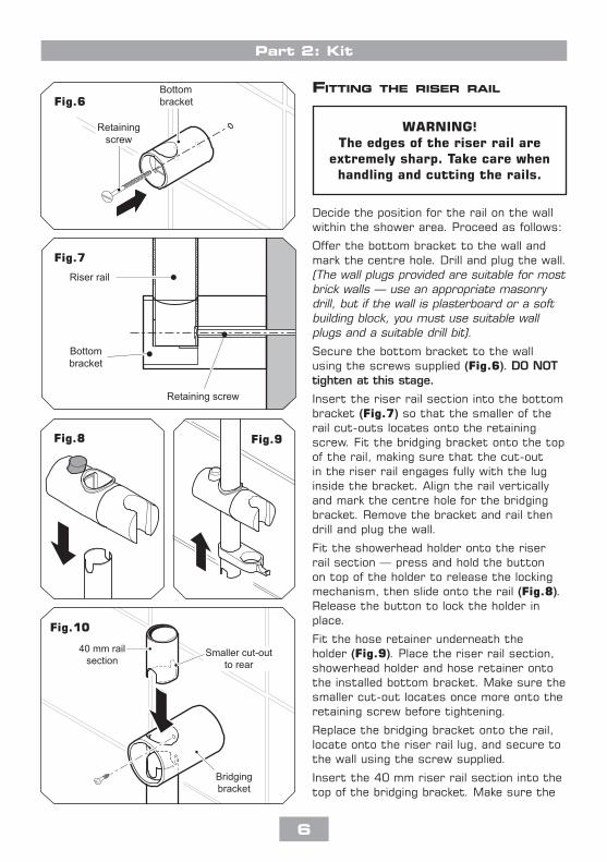
WArning!Theedgesoftheriserrailare
extremelysharp.Takecarewhenhandlingandcuttingtherails.
Bottombracket
Retainingscrew
Fig.6
Fig.8 Fig.9
Smaller cut-outto rear
Bridgingbracket
40 mm railsection
Fig.10
Retaining screw
Bottombracket
Riser rail
Fig.7
Fitting the riser rail
Decide the position for the rail on the wall within the shower area. Proceed as follows:
Offer the bottom bracket to the wall and mark the centre hole. Drill and plug the wall. (The wall plugs provided are suitable for most brick walls – use an appropriate masonry drill, but if the wall is plasterboard or a soft building block, you must use suitable wall plugs and a suitable drill bit).
Secure the bottom bracket to the wall using the screws supplied (Fig.6).DOnOTtightenatthisstage.
Insert the riser rail section into the bottom bracket (Fig.7) so that the smaller of the rail cut-outs locates onto the retaining screw. Fit the bridging bracket onto the top of the rail, making sure that the cut-out in the riser rail engages fully with the lug inside the bracket. Align the rail vertically and mark the centre hole for the bridging bracket. Remove the bracket and rail then drill and plug the wall.
Fit the showerhead holder onto the riser rail section — press and hold the button on top of the holder to release the locking mechanism, then slide onto the rail (Fig.8). Release the button to lock the holder in place.
Fit the hose retainer underneath the holder (Fig.9). Place the riser rail section, showerhead holder and hose retainer onto the installed bottom bracket. Make sure the smaller cut-out locates once more onto the retaining screw before tightening.
Replace the bridging bracket onto the rail, locate onto the riser rail lug, and secure to the wall using the screw supplied.
Insert the 40 mm riser rail section into the top of the bridging bracket. Make sure the

�
Part 2: Kit
smaller cut-out in the rail is facing towards the rear and secure to the bracket with the small screw supplied (Fig.10).
Note: The screw will pass through the cut-out in the front of the riser rail and secure the rear of the riser rail to the bracket.
Push fit a bracket end trim onto each bracket (Fig.11) and insert the riser rail trim into the top of the riser rail assembly (Fig.12).
Fig.12
Fig.11

�
Part 2: Kit
WArning!Checktherearenohiddencablesorpipesbeforedrillingholesforwallplugs.Usegreatcarewhen
usingpowertoolsnearwater.Theuseofaresidualcurrentdevice
(rCD)isrecommended.
heated water pipe routed inside the riser railThisoptionisforinstallingathroughtheceilingriserrailforusewithafallingsupply.
ImportaNt:Usethefollowinginstructionsafterinstallingthemixingunitandwhenplumbingtheunit.
ImportaNt:Beforedrillingholesintheceilingorwallsurfacemakesurethereisenoughclearanceabovetheceilingtoaccommodatetheentryoftheriserrailandheatedwaterpipe.
If the mixing unit is installed in a loft area the following requirements must be met for future servicing purposes:
a. There must be no risk of the mixing unit or heated water pipe becoming frozen.
b. The mixing unit MuST NOT be covered with any form of insulating material that may give rise to electrical circuits overheating during periods of high ambient temperature.
c. A safe means of access must be provided into the loft, e.g. via a fixed loft ladder.
d. The mixing unit MuST be installed in an accessible and safe location.
e. Ceiling joists must be adequately boarded to provide safe and unobstructed access to, from and around the mixing unit.
f. There must be adequate lighting in the loft for servicing purposes.
FallInG SuPPly — GEnERal
WArning!Theedgesoftheriserrailare
extremelysharp.Takecarewhenhandlingandcuttingtherails.

�
Part 2: Kit
Components
Fig.13 shows the parts required to install the short version of the through the ceiling riser rail kit.
1. 940 mm riser rail section
2. Guide bracket
3. Showerhead holder
4. Hose retainer
5. Bottom bracket
6. Bracket end trim (2 off)
7. Ceiling trim
8. Spacer — optional (2 off)
9. Outlet connector
10. Securing clip
Screws and fittings
InSTallaTIon oPTIon 2: FallInG SuPPly —ThRouGh ThE CEIlInG RISER RaIl (ShoRT)
Fig.13
7
2
86
1
3
4
5
9
8
10
6

�0
Part 2: Kit
50 mm minimumclearance.
Riser rail long enough toclear ceiling joists, etc.
Bottom bracket
Guide bracket
Showerhead holder
Ceiling
Spacer(25 mm depth)
Spacer(25 mm depth)
Fitting the through Ceiling riser rail
When determining your required riser rail length allow a minimum distance of 50 mm between the ceiling and the uppermost bracket. Make sure there is sufficient length of riser rail above the ceiling level to overcome any obstructions to running the heated water pipe, such as the height of the ceiling joist (Fig.14).
Note: The spacers supplied provide an additional 25 mm of depth for the riser rail installation to avoid hitting a loft ceiling joist (Fig.14).
ProcedureAssemble the bottom and guide brackets onto the 940 mm section of rail. Make sure the rail engages fully into the brackets.
Hold the riser rail assembly up to the wall and align vertically to determine the height of the showerhead and control panel when installed.
Mark the position for the guide bracket. Remove the assembly then drill and plug the wall.
Secure the guide bracket (and spacer) to the wall.
Slide the riser rail up through the guide bracket until it touches the ceiling (Fig.15). using a spirit level, align the riser rail vertically and mark the centre hole position of the rail on the ceiling. Remove the rail.
using a 26 mm hole cutter, drill the ceiling opening.
Fit the riser rail into the bottom bracket and secure with the small screw supplied.
ImportaNt:Beforesecuringtherailtothebracket,testfittheoutletconnectorandcliptomakesuretheywillfitintothebottombracketwiththerailinplace.
Feed the riser rail assembly through the base of the guide bracket and into the ceiling opening. using a spirit level, align the riser rail vertically and mark the bottom bracket centre hole position.
Fig.14
Mark the positionwhere rail
enters the ceiling
Riser rail
Guide bracket
Fig.15

��
Part 2: Kit
ImportaNt:Remembertoaddtheextralengthofrailtothemeasurementstoclearanyobstructionsabovetheceilinglevel(Fig.14)beforemarking.
Remove the assembly then drill and plug the wall.
Slide the hose retainer onto the lower rail section. Fit the showerhead holder onto the riser rail section — press and hold the button on top of the holder to release the locking mechanism, then slide onto the rail (Fig.16). Release the button to lock the holder in place.
Fit the riser rail through the guide bracket before sliding the ceiling trim over the rail end, and feeding the rail into the ceiling opening (Fig.17).
Secure the rail and bottom bracket assembly to the wall using the screw supplied (Fig.18).
Slide the ceiling trim up to the ceiling.
Riser rail
Guide bracket
Ceiling trimFig.17
Fig.16
Bottombracket
SpacerRetainingscrew
Riser rail
Fig.18

�2
Part 2: Kit
InSTallaTIon oPTIon �: FallInG SuPPly —ThRouGh ThE CEIlInG RISER RaIl (lonG)
Fig.19Components
Fig.19 shows the parts required to install the through the ceiling riser rail kit. Note that parts (1) and (3) can be interchanged depending on the user’s requirements.
1. 940 mm riser rail section
2. Guide bracket
3. 700 mm riser rail section
4. Bridging bracket
5. Showerhead holder
6. Hose retainer
7. Bottom bracket
8. Bracket end trim (3 off)
9. Ceiling trim
10. Spacer — optional (3 off)
11. Outlet connector
12. Securing clip
Screws and fittings
1
2
3
4
5
67
8
9 10
8
8
10
10
11
12

��
Part 2: Kit
Fitting the through Ceiling riser rail
Note: There are two lengths of riser rail supplied to cater for differing layouts and ceiling heights. It may be necessary to shorten one of the riser rail sections using a suitable hacksaw or pipe cutter.
When determining your required riser rail length allow a minimum distance of 50 mm between the ceiling and the uppermost bracket. Make sure there is sufficient length of riser rail above the ceiling level to overcome any obstructions to running the heated water pipe, such as the height of the ceiling joist (Fig.20).
Note: The spacers supplied provide an additional 25 mm of depth for the riser rail installation to avoid hitting a loft ceiling joist (Fig.20).
ProcedureImportaNt:Theproceduregivenhereusesthe700mmrailsectionforthelowersectionandthe940mmrailsectiontoenterintotheceiling.
Assemble the bottom and bridging brackets onto the 700 mm section of rail. Make sure the rail engages fully into the brackets.
Hold the riser rail assembly up to the wall and align vertically to determine the height of the showerhead and control panel when installed.
Mark the centre hole position for the bridging bracket and remove the assembly. Drill and plug the wall.
Secure temporarily the guide bracket (and spacer, if used) to the bridging bracket point.
Fit the bottom bracket to the riser rail and slide the rail section up through the guide
WarNINg!theedgesoftheriserrailare
extremelysharp.takecarewhenhandlingandcuttingtherails.
50 mm minimumclearance.
Upper riser rail long enough toclear ceiling joists, etc.
Bridging bracket
Guide bracket
Lower riser rail
Showerhead holder
Ceiling
Spacer(25 mm depth)
Spacer(25 mm depth)
Upper riser rail
Fig.20

��
Part 2: Kit
Retainingscrew
Smaller cut-outto rear
Bridgingbracket
Upperriser railsection
Mark the positionwhere rail
enters the ceiling
Riser rail
Guide bracket
Fig.21bracket until it touches the ceiling (Fig.21). Align the rail vertically. Mark the centre hole position of the rail on the ceiling. Remove the rail section and the guide bracket and, using a 26 mm hole cutter, drill the ceiling opening.
Fit the bridging bracket (and spacer) to the wall using the screw supplied, making sure the small lug inside the bracket faces down.
Measure the 940 mm rail (for the upper section of rail) and mark the required length to fit between the bridging bracket and into the ceiling. Remember to add the extra length of rail onto the measurements to clear any obstructions above the ceiling level (Fig.20). Cut the riser rail to length and deburr.
If the upper rail section is sufficiently long, fix the guide bracket (and spacer) onto the wall for additional support (Fig.20).
Feed the cut upper riser rail though the guide bracket (if used) before sliding the ceiling trim down onto the rail. Slide the riser rail into the ceiling opening and drop back into the bridging bracket, with the smaller of the cut-outs facing towards the rear. Secure the rail to the bridging bracket using the small screw supplied (Fig.22).
Slide the ceiling trim up to the ceiling.
Fit the 700 mm riser rail into the bottom bracket with the smaller cut-outs facing towards the rear and secure with the small screw supplied.
ImportaNt:Beforesecuringtherail,testfittheoutletconnectorandcliptomakesureitwillfitintothebottombracketwiththerailinplace.
Fit the lower riser rail assembly into the base of the bridging bracket, making sure the small cut-out engages the bracket lug. using a spirit level, align the riser rail vertically and mark the bottom bracket centre hole position. Remove the assembly. Drill and plug the wall.
Slide the hose retainer onto the lower rail section.
Fig.22

��
Part 2: Kit
Bottombracket
SpacerRetainingscrew
Riser rail
Fig.24
Fig.23Fit the showerhead holder onto the riser rail section — press and hold the button on top of the holder to release the locking mechanism, then slide onto the rail (Fig.23). Release the button to lock the holder in place.
Refit the lower riser rail assembly into the base of the bridging bracket, again making sure the small cut-out engages the bracket lug. Secure the rail and bottom bracket assembly to the wall using the screw supplied (Fig.24).

��
Part 2: Kit
ImportaNt:Makesureallpipeworkconnectionstoandfromthemixingunithavebeencompletedbeforefittingtheoutletconnector.Referto‘Part3:Mixingunit’fordetails.
option 1: rear entry supply — Fitting the bulkhead
Connect the heated water pipe to a ½” BSP x 15 mm female thread elbow or straight coupler compression fitting(Fig.25).
Note:This fitting is not supplied as variations in installations requires selection of the most suitable fitting.
Screw the supplied male-thread connector into the female fitting (Fig.26) using PTFE tape to give a watertight joint.
Note:The male-thread connector supplied has a shoulder. If fitting into a flush wall, make an additional 8 mm allowance for this shoulder at the finished surface. The connector can be cut to size if required.
The threaded connector should protrude from the wall surface between 8 mm and 13 mm.
Make good the wall.
The bulkhead and its cover are supplied assembled. Separate the two halves by carefully prising apart at the smaller of the two elbow apertures.
Secure the elbow to the bulkhead body with the three screws supplied (Fig.27).
Screw the bulkhead assembly onto the threaded connector temporarily. Mark the position of the two fixing holes (Fig.28) securing the bulkhead to the wall.
Note:If screw thread protrudes too far out of the wall, it can be cut to the correct length using a hacksaw.
unscrew and remove the bulkhead assembly. Check the location of the pipe in the wall before drilling.
PluMbInG ConnECTIonS
8mm − 13mm
Finished surface
Fig.27
Fig.26
Fig.28
Appropriatefitting
Heated waterpipe
Fig.25
��
Part 2: Kit
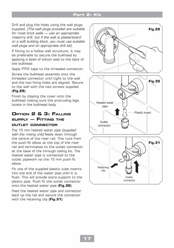
Drill and plug the holes using the wall plugs supplied. (The wall plugs provided are suitable for most brick walls – use an appropriate masonry drill, but if the wall is plasterboard or a soft building block, you must use suitable wall plugs and an appropriate drill bit).
If fitting to a hollow wall structure, it may be preferable to secure the bulkhead by applying a bead of silicon seal to the back of the bulkhead.
Apply PTFE tape to the threaded connector.
Screw the bulkhead assembly onto the threaded connector until tight to the wall and the two fixing holes are aligned. Secure to the wall with the two screws supplied (Fig.29).
Finish by clipping the cover onto the bulkhead making sure the protruding legs locate in the bulkhead body.
option 2 & 3: Falling
supply — Fitting the outlet ConneCtor
The 15 mm heated water pipe (supplied with the mixing unit) feeds down through the centre of the riser rail. This runs from the push-fit elbow at the top of the riser rail and terminates to the outlet connector at the base of the through ceiling kit. The heated water pipe is connected to the outlet pipework via the 15 mm push-fit elbow.
Fit one of the supplied plastic tube inserts into one end of the water pipe until it is flush. This will provide extra support to the plastic pipe. Push fit the outlet connector onto the heated water pipe (Fig.30).
Feed the heated water pipe and connector back up the rail and secure the connector with the retaining clip (Fig.31).
Fig.29
Outletconnector
Retainingclip
Fig.31
Outletconnector
Heated waterpipe
Plastic insert
Fig.30

��
Part 2: Kit
In the loft, trim the heated water pipe excess to length. Insert the remaining plastic tube insert the end of the water pipe and then push fit into the 15 mm elbow fitting (Fig.32).
Fit the bracket end trims onto the brackets.
FITTInG ThE hoSE and ShoWERhEadFeed the flexible hose through the hose retainer opening (Fig.33) so that it acts as a retaining ring (Water Regulations).
Screw the flexible hose to the bulkhead (Fig.34) or the outlet connector (Fig.35) and the other end to the showerhead. Make sure the supplied washers are in place at both ends of the flexible hose.
Place the showerhead into the holder and check that it fits correctly.
Note:The holder is slightly tapered and the showerhead and hose will only fit from one direction.
ImportaNt:Itistheconicalendofthehosewhichgripsintotheholder.Theshowerheadwillnotfitintheholderwithoutthehoseattached.
At this stage, disconnect the showerhead and lay aside until the shower unit has been commissioned.
ShowerheadBulkhead
Washers
Fig.33
Fig.34
Showerhead
Outletconnector
Washer
Fig.35
15 mm elbowfitting
Pipework to mixing unit(not supplied)
Heatedwater pipe
(up riser rail)
Plasticinsert
Ceiling
Fig.32

��
Part 2: Kit
Fig.36adJuSTInG ThE ShoWERhEad
Five showerhead patterns are available (Fig.36). Adjust the spray pattern by turning the bezel on the showerhead in either direction until the desired pattern is obtained.

20
Part 2: Kit
ClEanInG ThE ShoWERhEad
Before cleaning, turn off the unit at the mains supply to avoid the shower being accidentally switched on.
It is important to keep the showerhead clean to maintain the performance of the shower. The hardness of the water will determine the frequency of cleaning. For example, if the shower is used every day in a very hard water area, it may be necessary to clean the showerhead on a weekly basis.
Sprayplate removalThere is no need to remove the showerhead from the hose.
using the removal tool supplied (Fig.37), locate the raised ’bosses’ into the recesses in the sprayplate. Hold in firmly and twist anti-clockwise (Fig.38). This movement may turn the cartridge assembly as well until it reaches a ‘stop’.
Hold the cartridge firmly and continue to twist anti-clockwise. Having loosened the sprayplate, it can be unscrewed and removed completely.
Clean the sprayplate with a suitable brush or preferably leave it to soak overnight in a mild proprietary descalent. Make sure all traces of scale are removed and thoroughly rinse in clean water afterwards.
Before replacing the sprayplate, switch the water (and power) back on at the mains supply and direct the hose and showerhead to waste.
Turn the temperature control to cold.
Start the shower and set to maximum flow. This operation will flush out any loose scale deposits in the unit and showerhead. Stop after about thirty seconds.
Refit the sprayplate by screwing clockwise. use the tool to screw the sprayplate tight.
Sprayplatekey
Sprayplate
Fig.37
Fig.38

2�
Part 2: Kit
SPaRE PaRTS
ref. Description partNo.
1. Showerhead holder 83308410
2. Bridging bracket assembly (bracket, trim & spacer) 83309970
3. Bridging bracket 83309450
4. Guide bracket assembly (bracket, trim & spacer) 83309980
5. Guide bracket 7053477
6. Bottom bracket assembly (bracket, trim & spacer) 83309990
7. Bottom bracket (blank) 7053476
8. Bottom bracket 7053510
9. Bracket end trim 83308400
10. Spacer 7053505
11. Retaining clip 7053511
12. Hose connector 7053479
13. Ceiling trim 22011350
14. 40 mm riser rail section and end trim
7033485
15. 700 mm riser rail section 7033495
16. 940 mm riser rail section 7033484
17. Hose retainer 83308430
18. Flexible hoses available in the following sizes:
1.00 m in white, chrome and gold 1.25 m in white, chrome and gold 1.75 m in chrome only
19. 15 mm push-fit elbow 22011470
20. 5 mode rub clean showerhead 22011110
21. Bulkhead assembly 85500230
– All thread fitting 7032915
1
2
4
5
6
7
10
11 12
3
8
9
9
9
10
10
13
14
15
16
17
20
19
18
21

Triton Showers Triton Road Nuneaton Warwickshire CV11 4NR
Triton is a division of Norcros Group (Holdings) Limited
Customer Service: % 0870 067 3333
Scottish and Northern Ireland Customer Service: % 0845 762 6591
Trade Installer Hotline: % 0870 067 3767 Fax: 0870 067 3334
www.tritonshowers.co.uk
E mail: [email protected]
TRITON reserve the right to change product specification without prior notice. E&OA. © TRITON SHOWERS 2008
TrIToN STaNdard GuaraNTEETriton guarantee this product against defects arising from faulty workmanship or materials for a period of one year for domestic use only, from the date of purchase, provided that it has been installed by a competent person in full accordance with the fitting instructions.Any part found to be defective during this guarantee period we undertake to repair or replace at our option without charge so long as it has been properly maintained and operated in accordance with the operating instructions, and has not been subject to misuse or damage.This product must not be taken apart, modified or repaired except by a person authorised by Triton. This guarantee applies only to products installed within the United Kingdom and does not apply to products used commercially. This guarantee does not affect your statutory rights.