Embed Size (px)
Citation preview
MATRIX 6/816 Control Panel with Remote Keypads
Software Version 1.34
USER MANUAL
RINS545-7
CONTENTS
1. GENERAL OVERVIEW........................................................................................................................... 1 1.1 Keypad Buttons................................................................................................................................ 1 1.2 Keypad Display ................................................................................................................................ 2 1.3 Common Keypad Indications ............................................................................................................. 3 1.4 System Fault Indications................................................................................................................... 4
2. YOUR PANEL DETAILS ......................................................................................................................... 5 2.1 Zone Configuration........................................................................................................................... 5 2.2 Timers ............................................................................................................................................ 6 2.3 Arm Options .................................................................................................................................... 6 2.4 Your Servicing Company Details ........................................................................................................ 6 2.5 Fault tones ...................................................................................................................................... 6 2.6 Open zones ..................................................................................................................................... 6 2.7 Hidden Display Mode........................................................................................................................ 7 2.8 Latching Alarms – Denmark, Norway, Finland & Sweden only .............................................................. 7 2.9 System Faults – Norway, Denmark, Finland and Sweden ..................................................................... 7
3. ARMING AND DISARMING THE PANEL .................................................................................................. 8 3.1 Arm Modes Explained ....................................................................................................................... 8 3.2 Arming the Panel ............................................................................................................................. 8 3.3 Disarming the Panel ......................................................................................................................... 9 3.4 Disarm After Alarm......................................................................................................................... 10 3.5 Resetting the Alarm When the Panel is Disarmed.............................................................................. 10 3.6 Activating Alarms from the Keypad .................................................................................................. 11 3.7 Duress Arming / Disarming ............................................................................................................. 11 3.8 Display Event in FTA Mode.............................................................................................................. 11
4. USER MENU ...................................................................................................................................... 12 4.1 Enter/Exit User Menu...................................................................................................................... 12 4.2 Chime On/Off ................................................................................................................................ 13 4.3 Arm With Omits (Bypass)................................................................................................................ 13 4.4 View Event Log.............................................................................................................................. 13 4.5 Change Keypad Volume.................................................................................................................. 14 4.6 Change Keypad Brightness.............................................................................................................. 14 4.7 Change System Time (Master User Only) ......................................................................................... 14 4.8 Change System Date (Master User Only).......................................................................................... 15 4.9 Change User Code (Master User Only) ............................................................................................. 16 4.10 Activating PGM from the Keypad (Master User Only) ....................................................................... 16 4.11 Open 1Hr Download Window (Master User Only) ............................................................................ 17 4.12 System Test (Master User Only) .................................................................................................... 17
5. DETAILED DESCRIPTION ................................................................................................................... 18 5.1 Operation modes ........................................................................................................................... 18 5.2 Entry/Exit Procedure ...................................................................................................................... 19
6. VIEWING THE EVENT LOG AFTER A ZONE ALARM ............................................................................... 20 6.1 Event Log Information.................................................................................................................... 21 6.2 Zone Type Descriptions .................................................................................................................. 24
7. QUICK REFERENCE............................................................................................................................ 25
Matrix 6/816 User Manual
RINS545-7 Page 1
1. GENERAL OVERVIEW
Thank you for purchasing the Matrix control panel which has been designed and manufactured using the latest technology. This manual has been written to help you become familiar with all the available functions, enabling to get the best out of your alarm system.
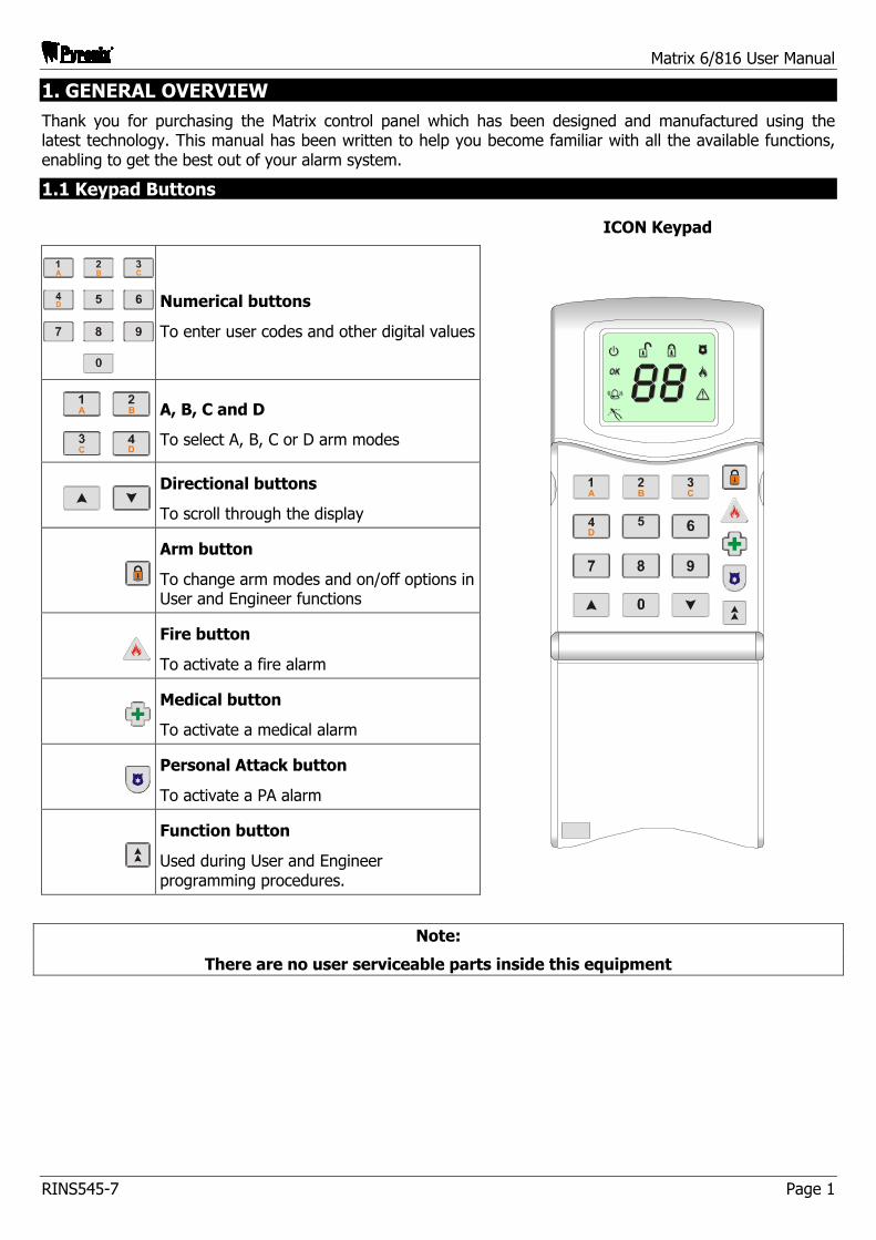
1.1 Keypad Buttons
ICON Keypad
Numerical buttons
To enter user codes and other digital values
A, B, C and D
To select A, B, C or D arm modes
Directional buttons
To scroll through the display
Arm button
To change arm modes and on/off options in User and Engineer functions
Fire button
To activate a fire alarm
Medical button
To activate a medical alarm
Personal Attack button
To activate a PA alarm
Function button
Used during User and Engineer programming procedures.
Note:
There are no user serviceable parts inside this equipment
Matrix 6/816 User Manual
Page 2 RINS545-7
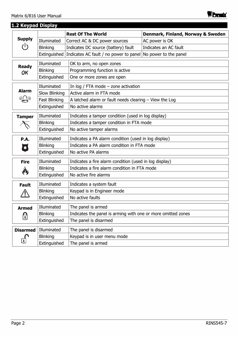
1.2 Keypad Display
Rest Of The World Denmark, Finland, Norway & Sweden
Illuminated Correct AC & DC power sources AC power is OK
Blinking Indicates DC source (battery) fault Indicates an AC fault
Supply
Extinguished Indicates AC fault / no power to panel No power to the panel
Illuminated OK to arm, no open zones
Blinking Programming function is active Ready
Extinguished One or more zones are open
Illuminated In log / FTA mode – zone activation
Slow Blinking Active alarm in FTA mode
Fast Blinking A latched alarm or fault needs clearing – View the Log
Alarm
Extinguished No active alarms
Illuminated Indicates a tamper condition (used in log display)
Blinking Indicates a tamper condition in FTA mode Tamper
Extinguished No active tamper alarms
Illuminated Indicates a PA alarm condition (used in log display)
Blinking Indicates a PA alarm condition in FTA mode P.A.
Extinguished No active PA alarms
Illuminated Indicates a fire alarm condition (used in log display)
Blinking Indicates a fire alarm condition in FTA mode Fire
Extinguished No active fire alarms
Illuminated Indicates a system fault
Blinking Keypad is in Engineer mode Fault
Extinguished No active faults
Illuminated The panel is armed
Blinking Indicates the panel is arming with one or more omitted zones Armed
Extinguished The panel is disarmed
Illuminated The panel is disarmed
Blinking Keypad is in user menu mode Disarmed
Extinguished The panel is armed
Matrix 6/816 User Manual
RINS545-7 Page 3
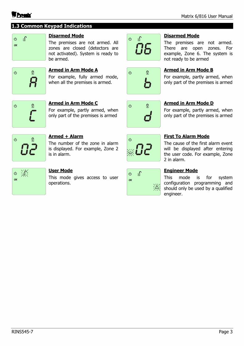
1.3 Common Keypad Indications
Disarmed Mode
The premises are not armed. All zones are closed (detectors are not activated). System is ready to be armed.
Disarmed Mode
The premises are not armed. There are open zones. For example, Zone 6. The system is not ready to be armed
Armed in Arm Mode A
For example, fully armed mode, when all the premises is armed.
Armed in Arm Mode B
For example, partly armed, when only part of the premises is armed
Armed in Arm Mode C
For example, partly armed, when only part of the premises is armed
Armed in Arm Mode D
For example, partly armed, when only part of the premises is armed
Armed + Alarm
The number of the zone in alarm is displayed. For example, Zone 2 is in alarm.
First To Alarm Mode
The cause of the first alarm event will be displayed after entering the user code. For example, Zone 2 in alarm.
User Mode
This mode gives access to user operations.
Engineer Mode
This mode is for system configuration programming and should only be used by a qualified engineer.
Matrix 6/816 User Manual
Page 4 RINS545-7
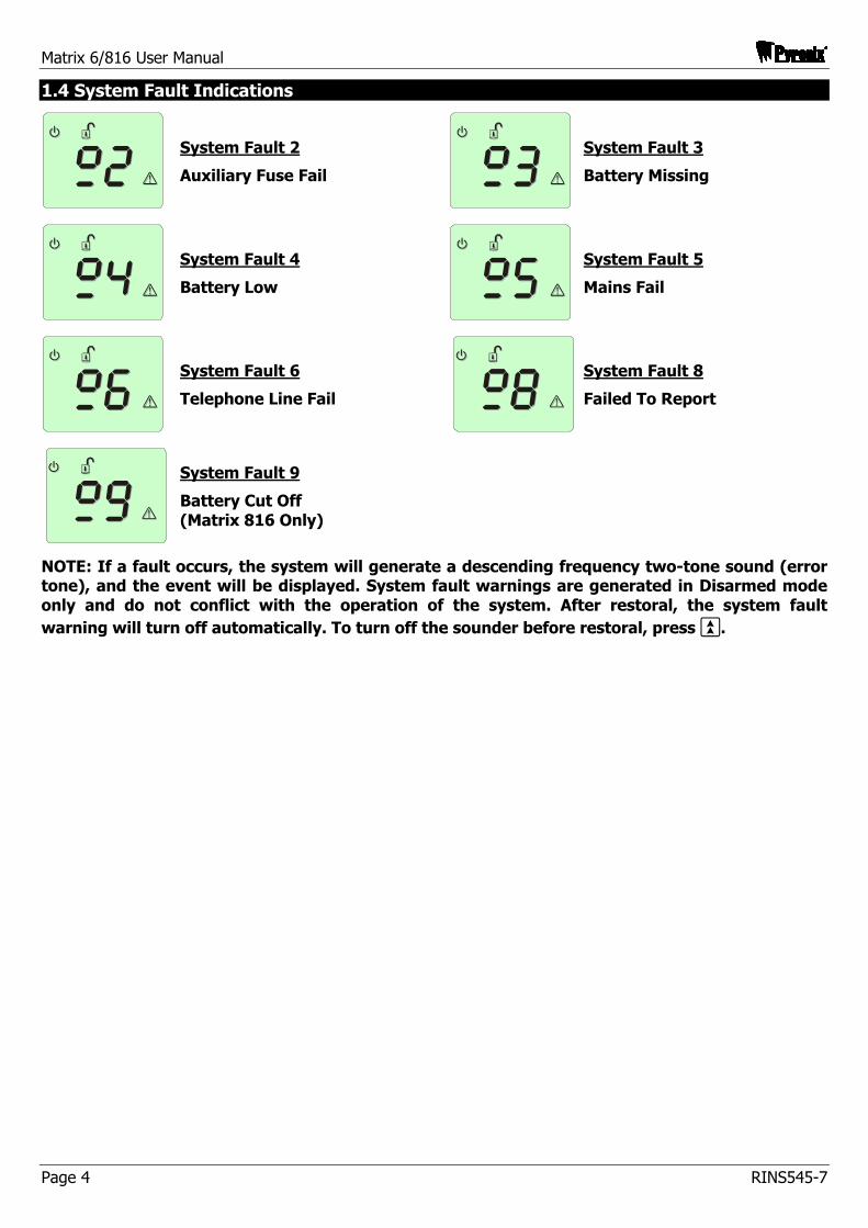
1.4 System Fault Indications
System Fault 2
Auxiliary Fuse Fail
System Fault 3
Battery Missing
System Fault 4
Battery Low
System Fault 5
Mains Fail
System Fault 6
Telephone Line Fail
System Fault 8
Failed To Report
System Fault 9
Battery Cut Off (Matrix 816 Only)
NOTE: If a fault occurs, the system will generate a descending frequency two-tone sound (error tone), and the event will be displayed. System fault warnings are generated in Disarmed mode only and do not conflict with the operation of the system. After restoral, the system fault warning will turn off automatically. To turn off the sounder before restoral, press `.
Matrix 6/816 User Manual
RINS545-7 Page 5
2. YOUR PANEL DETAILS
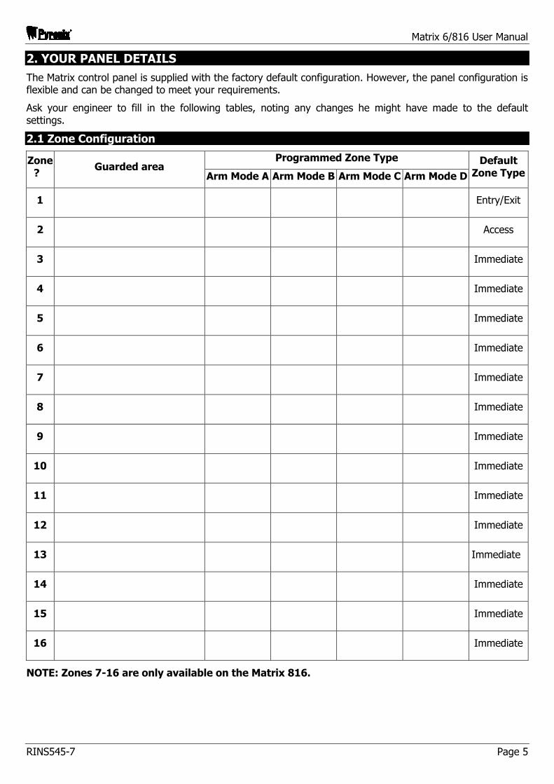
The Matrix control panel is supplied with the factory default configuration. However, the panel configuration is flexible and can be changed to meet your requirements.
Ask your engineer to fill in the following tables, noting any changes he might have made to the default settings.
2.1 Zone Configuration
Programmed Zone Type Zone?
Guarded area Arm Mode A Arm Mode B Arm Mode C Arm Mode D
Default Zone Type
1 Entry/Exit
2 Access
3 Immediate
4 Immediate
5 Immediate
6 Immediate
7 Immediate
8 Immediate
9 Immediate
10 Immediate
11 Immediate
12 Immediate
13 Immediate
14 Immediate
15 Immediate
16 Immediate
NOTE: Zones 7-16 are only available on the Matrix 816.
Matrix 6/816 User Manual
Page 6 RINS545-7
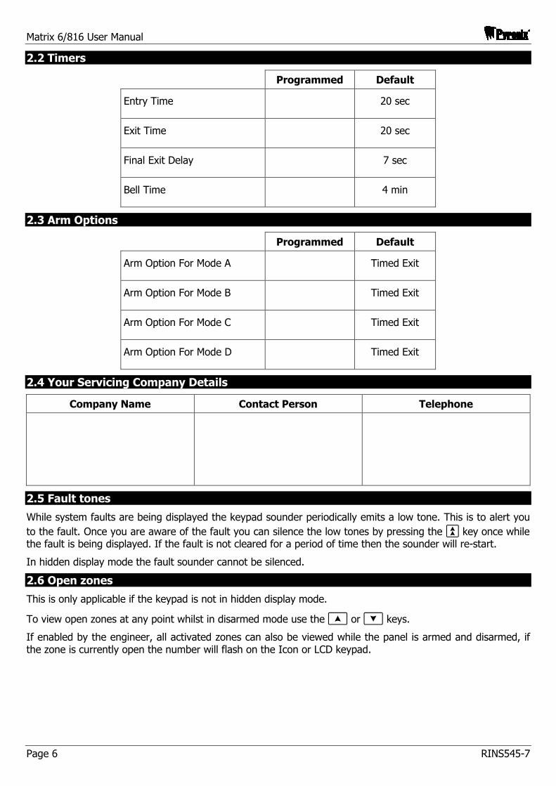
2.2 Timers
Programmed Default
Entry Time 20 sec
Exit Time 20 sec
Final Exit Delay 7 sec
Bell Time 4 min
2.3 Arm Options
Programmed Default
Arm Option For Mode A Timed Exit
Arm Option For Mode B Timed Exit
Arm Option For Mode C Timed Exit
Arm Option For Mode D Timed Exit
2.4 Your Servicing Company Details
Company Name Contact Person Telephone
2.5 Fault tones
While system faults are being displayed the keypad sounder periodically emits a low tone. This is to alert you to the fault. Once you are aware of the fault you can silence the low tones by pressing the ` key once while the fault is being displayed. If the fault is not cleared for a period of time then the sounder will re-start.
In hidden display mode the fault sounder cannot be silenced.
2.6 Open zones
This is only applicable if the keypad is not in hidden display mode.
To view open zones at any point whilst in disarmed mode use the [ or ] keys.
If enabled by the engineer, all activated zones can also be viewed while the panel is armed and disarmed, if the zone is currently open the number will flash on the Icon or LCD keypad.
Matrix 6/816 User Manual
RINS545-7 Page 7
2.7 Hidden Display Mode
The Matrix alarm panel incorporates a hidden display (confidential mode) feature that can be enabled / disabled by your installation engineer. This feature hides all of the panel information from the keypad display if the keypad has not been used for the last 20 seconds. In hidden display mode only the supply symbol will be visible. The keypad will remain in hidden display mode until a valid user code has been entered on the keypad.
Depending in which state the alarm panel is currently in, the first valid user code entry whilst in hidden display mode will have the following effects on the panel.
2.7.1 When Disarmed
If there are no system faults then the panel will come out of hidden display mode and automatically start the arming process. If there are any system faults pending then the keypad will drop out of hidden display mode and allow the system fault to display. The panel will not start the arming process until you re-enter your user code again.
2.7.2 When Armed
The panel will leave hidden display mode and start the disarm process.
2.7.3 When in Alarm
The panel will leave hidden display mode and drop into First To Alarm (FTA) mode.
2.7.4 When in First To Alarm (FTA) mode
If the keypad is allowed to drop back into hidden display mode whilst in FTA mode, then simply enter your user code again to re-display the FTA information.
NOTE: When in User Menu mode the keypad will drop into hidden display mode if no keys are pressed for 20 seconds. As long as a key is pressed at least once every 20 seconds then user mode will remain active. Care must be taken not to keep pressing invalid keystrokes as the alarm panel may interpret this as a key tamper attempt and force the panel into a tamper alarm.
2.8 Latching Alarms – Denmark, Norway, Finland & Sweden only
After each and every alarm event the panel will display a latched alarm indicator, until you reset the latched alarm yourself, by either viewing the event log or by re-arming the panel. Latched alarms are only displayed in disarmed mode, and are indicated by a fast flashing bell symbol on the keypad.
To clear the latched alarm indicator, you can either view the event log using the View Event Log user function, or alternatively by fully re-arming the panel again. If hidden display mode is enabled the keypad will not hide until the latched alarm is cleared.
2.9 System Faults – Norway, Denmark, Finland and Sweden
2.9.1 Latching System Faults
All system faults are latched. This means that once a system fault has been triggered, the display will continue to display the fault even if the fault is eventually removed from the system. To clear the latched fault, first remove the fault then view the event log.
Once you have entered and then left the View Event Log function, and if the system fault is no longer active, the system fault message will be removed from the display.
2.9.2 Latching Battery Faults
Battery faults may be latched if enabled by your installation engineer. This means that once a battery fault has occurred, the display will continue to display the fault even if the cause of the fault has been removed from the system. In this case you will need to contact your installation engineer to clear the battery fault from the display.
If your installation engineer has allowed you to reset battery faults, then the Latching System Faults procedure above will allow you to clear the fault.
Matrix 6/816 User Manual
Page 8 RINS545-7
3. ARMING AND DISARMING THE PANEL
3.1 Arm Modes Explained
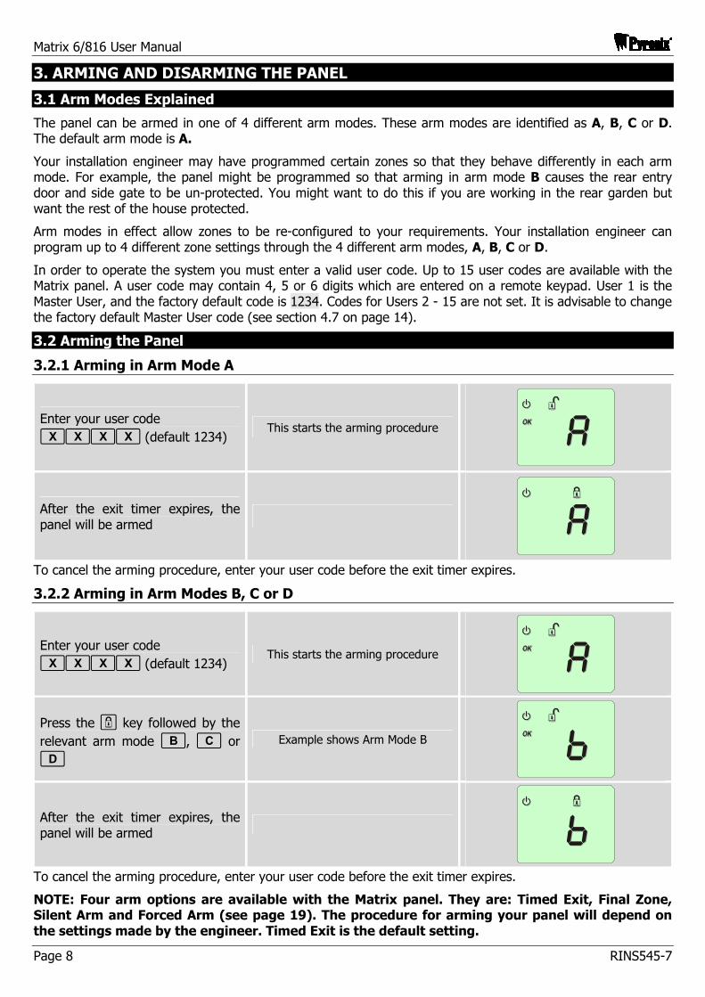
The panel can be armed in one of 4 different arm modes. These arm modes are identified as A, B, C or D. The default arm mode is A.
Your installation engineer may have programmed certain zones so that they behave differently in each arm mode. For example, the panel might be programmed so that arming in arm mode B causes the rear entry door and side gate to be un-protected. You might want to do this if you are working in the rear garden but want the rest of the house protected.
Arm modes in effect allow zones to be re-configured to your requirements. Your installation engineer can program up to 4 different zone settings through the 4 different arm modes, A, B, C or D.
In order to operate the system you must enter a valid user code. Up to 15 user codes are available with the Matrix panel. A user code may contain 4, 5 or 6 digits which are entered on a remote keypad. User 1 is the Master User, and the factory default code is 1234. Codes for Users 2 - 15 are not set. It is advisable to change the factory default Master User code (see section 4.7 on page 14).
3.2 Arming the Panel
3.2.1 Arming in Arm Mode A
Enter your user code ffff (default 1234)
This starts the arming procedure
After the exit timer expires, the panel will be armed
To cancel the arming procedure, enter your user code before the exit timer expires.
3.2.2 Arming in Arm Modes B, C or D
Enter your user code ffff (default 1234)
This starts the arming procedure
Press the - key followed by the relevant arm mode b, c or d
Example shows Arm Mode B
After the exit timer expires, the panel will be armed
To cancel the arming procedure, enter your user code before the exit timer expires.
NOTE: Four arm options are available with the Matrix panel. They are: Timed Exit, Final Zone, Silent Arm and Forced Arm (see page 19). The procedure for arming your panel will depend on the settings made by the engineer. Timed Exit is the default setting.
Matrix 6/816 User Manual
RINS545-7 Page 9
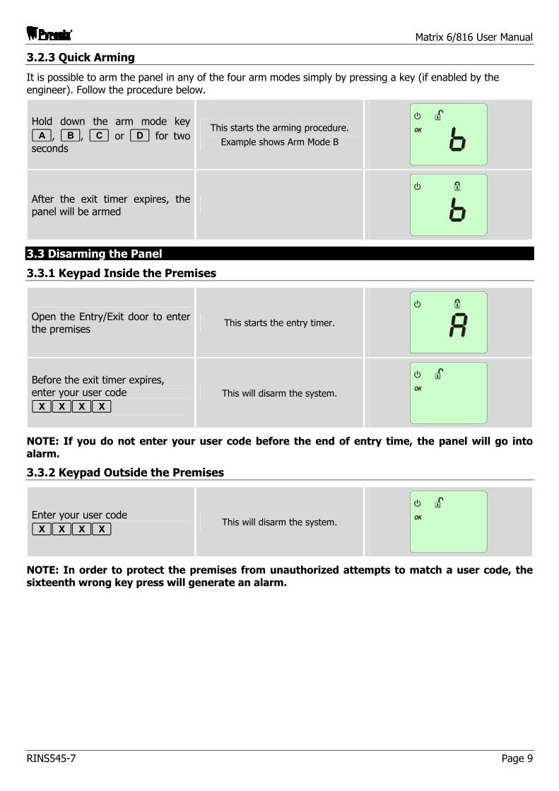
3.2.3 Quick Arming
It is possible to arm the panel in any of the four arm modes simply by pressing a key (if enabled by the engineer). Follow the procedure below.
Hold down the arm mode key a, b, c or d for two seconds
This starts the arming procedure.
Example shows Arm Mode B
After the exit timer expires, the panel will be armed
3.3 Disarming the Panel
3.3.1 Keypad Inside the Premises
Open the Entry/Exit door to enter the premises
This starts the entry timer.
Before the exit timer expires, enter your user code ffff
This will disarm the system.
NOTE: If you do not enter your user code before the end of entry time, the panel will go into alarm.
3.3.2 Keypad Outside the Premises
Enter your user code ffff
This will disarm the system.
NOTE: In order to protect the premises from unauthorized attempts to match a user code, the sixteenth wrong key press will generate an alarm.
Matrix 6/816 User Manual
Page 10 RINS545-7
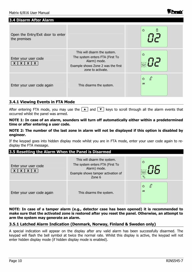
3.4 Disarm After Alarm
Open the Entry/Exit door to enter the premises
Enter your user code ffff
This will disarm the system. The system enters FTA (First To
Alarm) mode. Example shows Zone 2 was the first
zone to activate.
Enter your user code again This disarms the system.
3.4.1 Viewing Events in FTA Mode
After entering FTA mode, you may use the [ and ] keys to scroll through all the alarm events that occurred whilst the panel was armed.
NOTE 1: In case of an alarm, sounders will turn off automatically either within a predetermined time or after entering a user code.
NOTE 2: The number of the last zone in alarm will not be displayed if this option is disabled by engineer.
If the keypad goes into hidden display mode whilst you are in FTA mode, enter your user code again to re-display the FTA message.
3.5 Resetting the Alarm When the Panel is Disarmed
Enter your user code ffff
This will disarm the system.
The system enters FTA (First To Alarm) mode.
Example shows tamper activation of Zone 6
Enter your user code again This disarms the system.
NOTE: In case of a tamper alarm (e.g., detector case has been opened) it is recommended to make sure that the activated zone is restored after you reset the panel. Otherwise, an attempt to arm the system may generate an alarm.
3.5.1 Latched Alarm Indication (Denmark, Norway, Finland & Sweden only)
A special indication will appear on the display after any valid alarm has been successfully disarmed. The keypad will flash the bell symbol at twice the normal rate. Whilst this display is active, the keypad will not enter hidden display mode (if hidden display mode is enabled).
Matrix 6/816 User Manual
RINS545-7 Page 11
3.6 Activating Alarms from the Keypad
3.6.1 Personal Attack
Hold down the = button for 2 seconds.
The Personal Attack alarm will either activate all sounders or will be silent (the event will only be reported to the Central Monitoring Station) depending on how the system is programmed by the engineer.
3.6.2 Fire Alarm
Hold down the ' button for 2 seconds.
The Fire alarm will activate all sounders. External sounders will emit an intermittent tone and keypad sounders will emit a series of three rising tones.
3.6.3 Medical Alarm
Hold down the ; button for 2 seconds.
The Medical alarm will activate all sounders. Keypad sounders will emit a high frequency repeated tone.
3.7 Duress Arming / Disarming
3.7.1 What is a Duress Code?
A duress code is a personal user code that the alarm panel recognises as being entered under duress. By this we mean that the user has been forcibly made to enter their user code to disarm or arm the panel by another person.
The alarm panel treats this code like a proper user code and behaves as normal. The duress code will arm or disarm the system as normal. However, an emergency message is sent to your central monitoring station indicating that the panel was armed/disarmed under duress.
Method 1 Reverse the 3rd and the 4th digits of your user code when entering it into the keypad. For example, enter 1 2 4 3 instead of 1 2 3 4.
Method 2 Enter the duress code as programmed on your system. When you enter the duress code, the panel will act normally, however the duress event will be reported to the Central Monitoring Station.
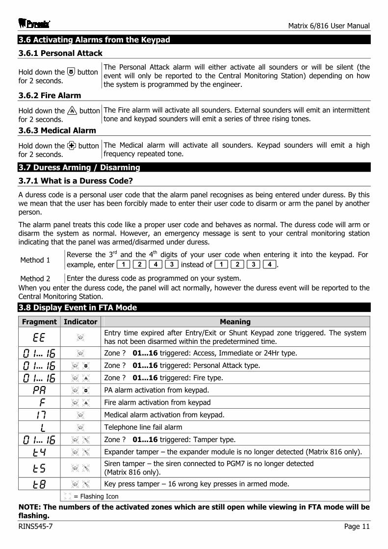
3.8 Display Event in FTA Mode
Fragment Indicator Meaning
EE K Entry time expired after Entry/Exit or Shunt Keypad zone triggered. The system has not been disarmed within the predetermined time.
pq...qy K Zone ? 01...16 triggered: Access, Immediate or 24Hr type.
pq...qy K X Zone ? 01...16 triggered: Personal Attack type.
pq...qy K Z Zone ? 01...16 triggered: Fire type.
PA K X PA alarm activation from keypad.
F K Z Fire alarm activation from keypad
qu K Medical alarm activation from keypad.
L K Telephone line fail alarm
pq...qy K S Zone ? 01...16 triggered: Tamper type.
Tr K S Expander tamper – the expander module is no longer detected (Matrix 816 only).
Tt K S Siren tamper – the siren connected to PGM7 is no longer detected (Matrix 816 only).
Ti K S Key press tamper – 16 wrong key presses in armed mode.
Ë = Flashing Icon NOTE: The numbers of the activated zones which are still open while viewing in FTA mode will be flashing.
Matrix 6/816 User Manual
Page 12 RINS545-7
4. USER MENU
Most of the user operations (except for arm, disarm and reset alarm) are only accessible from the user menu. User 1 is the Master User and has access to all user menu items, while access for Users 2 to 15 is limited.
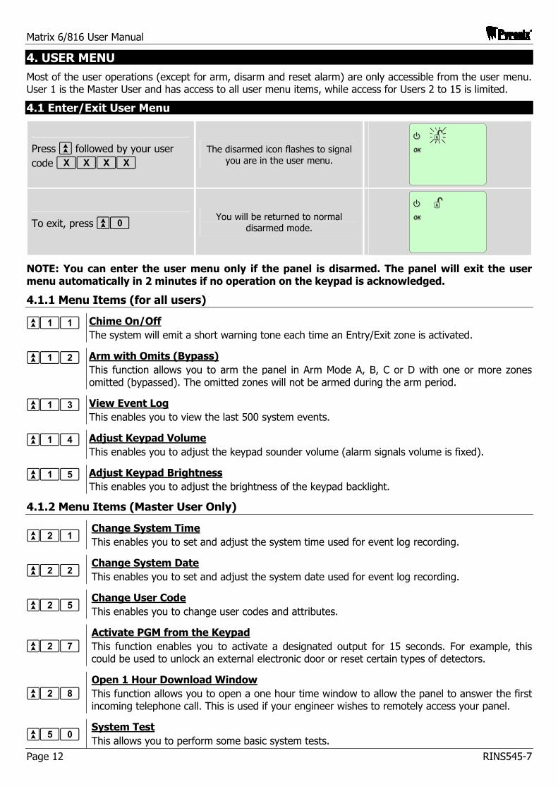
4.1 Enter/Exit User Menu
Press ` followed by your user code ffff
The disarmed icon flashes to signal you are in the user menu.
To exit, press `0 You will be returned to normal
disarmed mode.
NOTE: You can enter the user menu only if the panel is disarmed. The panel will exit the user menu automatically in 2 minutes if no operation on the keypad is acknowledged.
4.1.1 Menu Items (for all users)
`11 Chime On/Off The system will emit a short warning tone each time an Entry/Exit zone is activated.
`12 Arm with Omits (Bypass) This function allows you to arm the panel in Arm Mode A, B, C or D with one or more zones omitted (bypassed). The omitted zones will not be armed during the arm period.
`13 View Event Log This enables you to view the last 500 system events.
`14 Adjust Keypad Volume This enables you to adjust the keypad sounder volume (alarm signals volume is fixed).
`15 Adjust Keypad Brightness This enables you to adjust the brightness of the keypad backlight.
4.1.2 Menu Items (Master User Only)
`21 Change System Time This enables you to set and adjust the system time used for event log recording.
`22 Change System Date This enables you to set and adjust the system date used for event log recording.
`25 Change User Code This enables you to change user codes and attributes.
`27 Activate PGM from the Keypad This function enables you to activate a designated output for 15 seconds. For example, this could be used to unlock an external electronic door or reset certain types of detectors.
`28 Open 1 Hour Download Window This function allows you to open a one hour time window to allow the panel to answer the first incoming telephone call. This is used if your engineer wishes to remotely access your panel.
`50 System Test This allows you to perform some basic system tests.
Matrix 6/816 User Manual
RINS545-7 Page 13
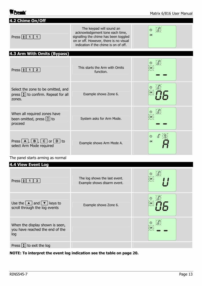
4.2 Chime On/Off
Press `11
The keypad will sound an acknowledgement tone each time,
signalling the chime has been toggled on or off. However, there is no visual
indication if the chime is on of off.
4.3 Arm With Omits (Bypass)
Press `12 This starts the Arm with Omits
function.
Select the zone to be omitted, and press ` to confirm. Repeat for all zones.
Example shows Zone 6.
When all required zones have been omitted, press - to proceed
System asks for Arm Mode.
Press a, b, c or d to select Arm Mode required
Example shows Arm Mode A.
The panel starts arming as normal
4.4 View Event Log
Press `13 The log shows the last event. Example shows disarm event.
Use the [ and ] keys to scroll through the log events
Example shows Zone 6.
When the display shown is seen, you have reached the end of the log
Press ` to exit the log
NOTE: To interpret the event log indication see the table on page 20.
Matrix 6/816 User Manual
Page 14 RINS545-7
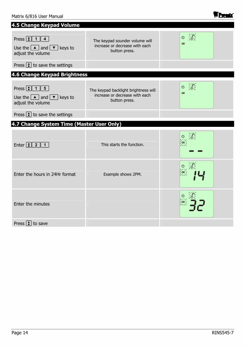
4.5 Change Keypad Volume
Press `14
Use the [ and ] keys to adjust the volume
The keypad sounder volume will increase or decrease with each
button press.
Press ` to save the settings
4.6 Change Keypad Brightness
Press `15
Use the [ and ] keys to adjust the volume
The keypad backlight brightness will increase or decrease with each
button press.
Press ` to save the settings
4.7 Change System Time (Master User Only)
Enter `21 This starts the function.
Enter the hours in 24Hr format Example shows 2PM.
Enter the minutes
Press ` to save
Matrix 6/816 User Manual
RINS545-7 Page 15
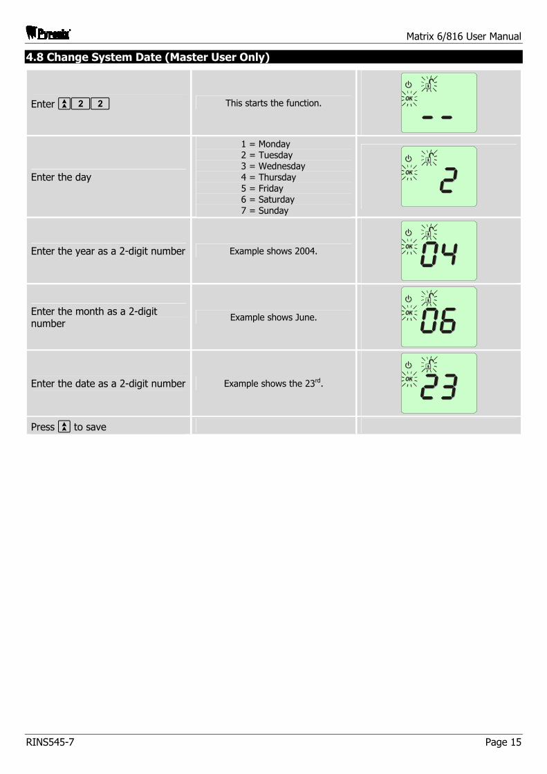
4.8 Change System Date (Master User Only)
Enter `22 This starts the function.
Enter the day
1 = Monday 2 = Tuesday 3 = Wednesday 4 = Thursday 5 = Friday 6 = Saturday 7 = Sunday
Enter the year as a 2-digit number Example shows 2004.
Enter the month as a 2-digit number
Example shows June.
Enter the date as a 2-digit number Example shows the 23rd.
Press ` to save
Matrix 6/816 User Manual
Page 16 RINS545-7
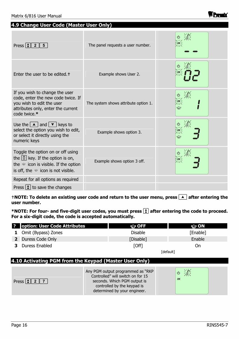
4.9 Change User Code (Master User Only)
Press `25 The panel requests a user number.
Enter the user to be edited.� Example shows User 2.
If you wish to change the user code, enter the new code twice. If you wish to edit the user attributes only, enter the current code twice.*
The system shows attribute option 1.
Use the [ and ] keys to select the option you wish to edit, or select it directly using the numeric keys
Example shows option 3.
Toggle the option on or off using the - key. If the option is on, the k icon is visible. If the option is off, the k icon is not visible.
Example shows option 3 off.
Repeat for all options as required
Press ` to save the changes
�NOTE: To delete an existing user code and return to the user menu, press [ after entering the user number.
*NOTE: For four- and five-digit user codes, you must press ` after entering the code to proceed. For a six-digit code, the code is accepted automatically.
? option: User Code Attributes OFF ON 1 Omit (Bypass) Zones Disable [Enable] 2 Duress Code Only [Disable] Enable 3 Duress Enabled [Off] On [default]
4.10 Activating PGM from the Keypad (Master User Only)
Press `27
Any PGM output programmed as “RKP Controlled” will switch on for 15 seconds. Which PGM output is
controlled by the keypad is determined by your engineer.
Matrix 6/816 User Manual
RINS545-7 Page 17
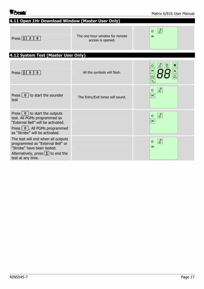
4.11 Open 1Hr Download Window (Master User Only)
Press `28 The one-hour window for remote
access is opened.
4.12 System Test (Master User Only)
Press `50 All the symbols will flash.
Press 0 to start the sounder test
The Entry/Exit tones will sound.
Press 0 to start the outputs test. All PGMs programmed as “External Bell” will be activated.
Press 0, All PGMs programmed as “Strobe” will be activated.
The test will end when all outputs programmed as “External Bell” or “Strobe” have been tested. Alternatively, press ` to end the test at any time.
Matrix 6/816 User Manual
Page 18 RINS545-7
5. DETAILED DESCRIPTION
This section is devoted to a more detailed description of the main panel features. If you require any information beyond the present manual, please contact your servicing company or the installer of your alarm system.
5.1 Operation modes
The panel is in operation for 24 hours a day. Two basic operation modes are distinguished: ARMED mode and DISARMED mode.
DISARMED
In disarmed mode all zones are disarmed, apart from Fire, Personal Attack, 24 Hr and Tamper, which are active for 24 hours a day. Wiring and PIR detector integrity can be supervised by the panel (if programmed by the engineer) to monitor. This function is helpful to promptly detect intruder’s attempts to deactivate the system even when the panel is not armed.
ARMED
In this mode all enabled zones are active, and if triggered will generate an alarm condition. If an alarm is triggered, internal and external sounders will operate for a programmed period of time and the alarm event will be reported to the Central Monitoring Station. Upon alarm time expiry the system will automatically rearm.
5.1.1 Available Arm Modes
The system may be armed in four different modes, A, B, C or D.
Arm Mode A Full arm mode. All zones are armed.
Arm Mode ? Partial arm mode. Some of the zones are not armed.
Arm Mode C Partial arm mode. Some of the zones are not armed.
Arm Mode D Partial arm mode. Some of the zones are not armed.
Your engineer will programme the zones to suit your premises.
5.1.2 Alarm Mode
If the alarm system is triggered, it will generate an alarm state causing the following activations:
The internal keypad sounder will activate for the pre-set period of time.
The external sounder will activate for the pre-set time period, and the strobe lamp will activate until the user resets the alarm.
A message will be reported to the Central Monitoring Station via telephone or other dedicated channels. Voice messages will be sent to the prescribed telephone numbers.
5.1.3 First to Alarm Mode (FTA)
When the system is in alarm it can be reset by entering a valid user code. Entering the user code in this case will allow the panel to enter FTA mode, and the first alarm event will be displayed (any post alarm events may be viewed by pressing the scroll buttons [ and ], although this feature is not available in Denmark, Norway, Finland or Sweden). In order to reset the panel to Disarmed mode you must enter the user code once more.
Matrix 6/816 User Manual
RINS545-7 Page 19
5.2 Entry/Exit Procedure
Follow the procedures below for arming the alarm panel before leaving the premises, and for entering the premises and disarming the alarm panel:
ENTRY
When the panel is armed, entering the premises using the Entry/Exit zone will trigger the Entry timer. The system counts down the preset entry time and the internal sounder warning tone is heard. Access zones triggered during the countdown period will be ignored. If no correct user code is entered before the end of count down period, or entry to the premises has been undertaken by an incorrect route, the panel will go into the alarm state.
EXIT
After entering a user code the system will count down the preset exit time and the internal sounder will beep. After the procedure is complete, the internal sounder beep will cease and the panel will be armed. If any of the zones are opened whilst the panel is arming, the panel will generate an error tone.
5.2.1 Available Arm Options
Timed Exit You can exit the premises while arming within a specified period of time depending on the condition of the zones. After you start arming the panel the exit time countdown timer will operate for the pre-set time and the internal sounder high tone will be heard. You should leave the premises within this time period by the designated route. Upon the end of countdown, if all zones under arming are closed (not activated), the internal sounder will emit the confirmation tone and the system will be armed. If any of the zones (Entry/Exit, Access and Immediate) are triggered during exit time, the countdown will hold and the internal sounder tone will change to the error (low) tone until the activated zones are closed. After the zones are closed the countdown timer will proceed.
Final Door There is no time limitation for leaving premises while arming and the system will be armed at any time when the final door is closed. The internal sounder high tone beep will be heard when arming starts until the door is closed. If the door is opened and/or other zones are activated while arming, the internal sounder tone will change to the error (low) tone. After the door is closed there will be a time delay (0…99 seconds, 7 seconds by default) until the system is armed and the internal sounder will mute. A single confirmation tone will denote the delay time start (ready to arm) and expiry (armed).
Silent Arm You may leave premises while arming within a pre-determined period of time by the designated route without any audible indication. Upon expiry of the exit time the system will be armed if all zones under arming are closed. Otherwise, arming of the system will be cancelled and the panel will generate an alarm signalled by internal sounder warning only.
Forced Arm Arming takes place within a pre-determined period of time irrespective of whether all of the zones under arming are closed. After you start arming the panel the internal sounder high tone will be heard. If any of the zones under arming are open (activated) the internal sounder will change to the error (low) tone. Upon expiry of the exit time the panel will be armed and the sounder will turn off. Open zones (if there are any) will be omitted (bypassed) until closed.
Matrix 6/816 User Manual
Page 20 RINS545-7
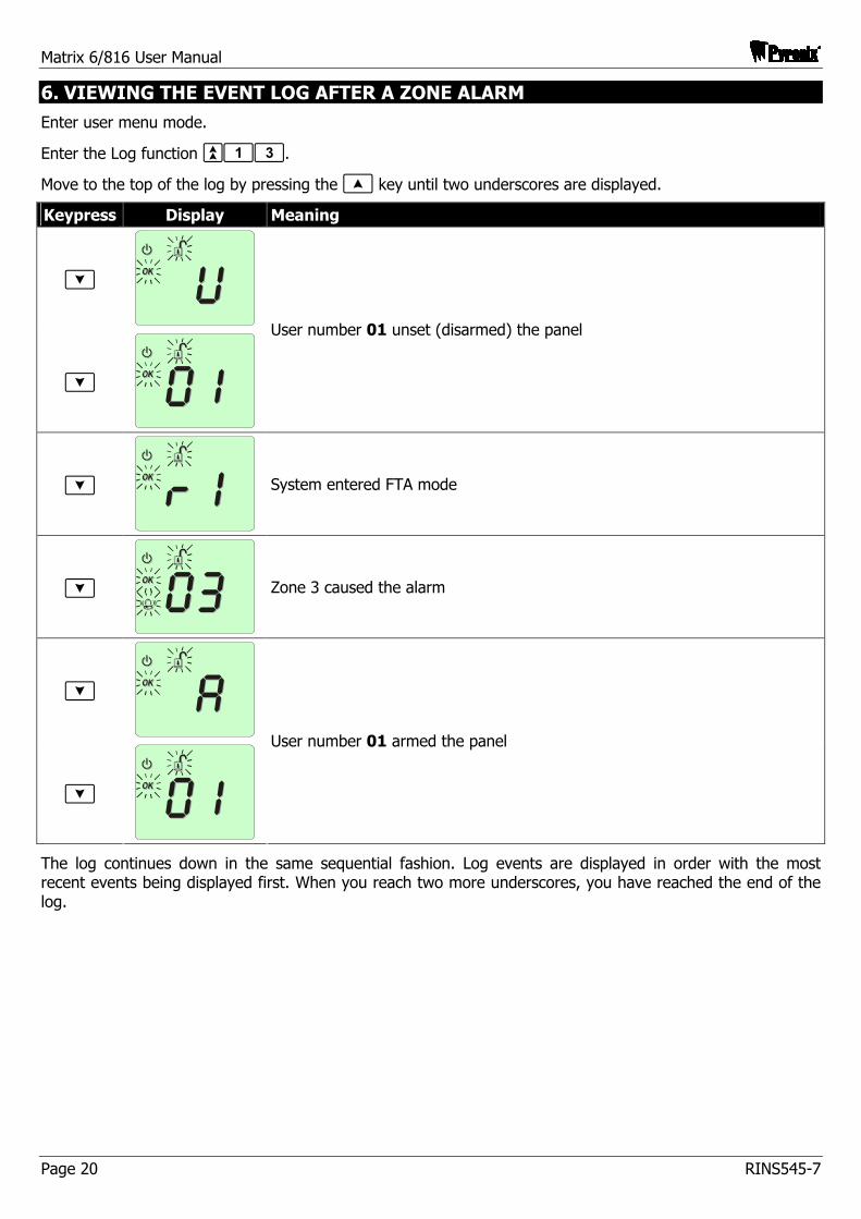
6. VIEWING THE EVENT LOG AFTER A ZONE ALARM
Enter user menu mode.
Enter the Log function `13.
Move to the top of the log by pressing the [ key until two underscores are displayed.
Keypress Display Meaning
]
]
User number 01 unset (disarmed) the panel
]
System entered FTA mode
]
Zone 3 caused the alarm
]
]
User number 01 armed the panel
The log continues down in the same sequential fashion. Log events are displayed in order with the most recent events being displayed first. When you reach two more underscores, you have reached the end of the log.
Matrix 6/816 User Manual
RINS545-7 Page 21
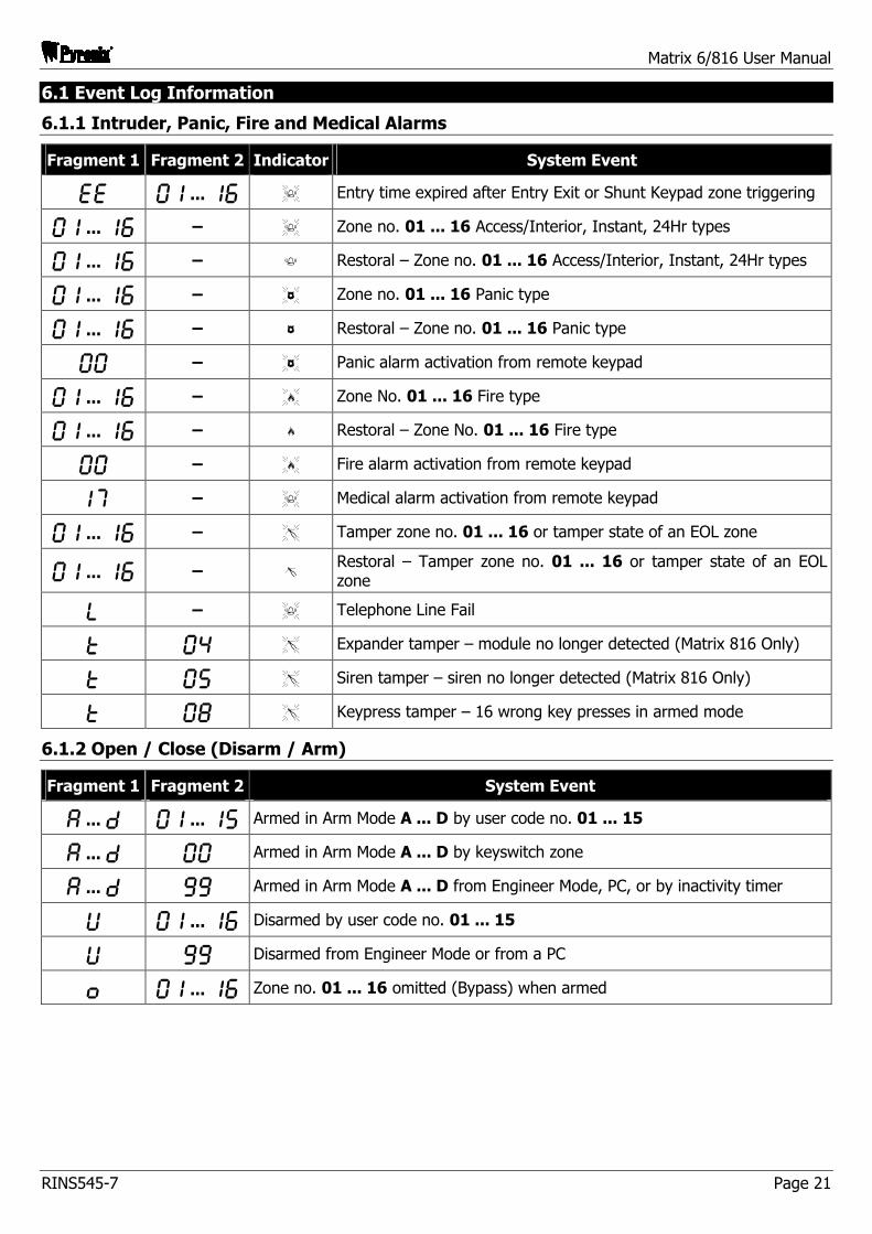
6.1 Event Log Information
6.1.1 Intruder, Panic, Fire and Medical Alarms
Fragment 1 Fragment 2 Indicator System Event
EE pq ... qy K Entry time expired after Entry Exit or Shunt Keypad zone triggering
pq ... qy – K Zone no. 01 ... 16 Access/Interior, Instant, 24Hr types
pq ... qy – k Restoral – Zone no. 01 ... 16 Access/Interior, Instant, 24Hr types
pq ... qy – X Zone no. 01 ... 16 Panic type
pq ... qy – x Restoral – Zone no. 01 ... 16 Panic type
pp – X Panic alarm activation from remote keypad
pq ... qy – Z Zone No. 01 ... 16 Fire type
pq ... qy – z Restoral – Zone No. 01 ... 16 Fire type
pp – Z Fire alarm activation from remote keypad
qu – K Medical alarm activation from remote keypad
pq ... qy – S Tamper zone no. 01 ... 16 or tamper state of an EOL zone
pq ... qy – s Restoral – Tamper zone no. 01 ... 16 or tamper state of an EOL zone
L – K Telephone Line Fail
T pr S Expander tamper – module no longer detected (Matrix 816 Only)
T pt S Siren tamper – siren no longer detected (Matrix 816 Only)
T pi S Keypress tamper – 16 wrong key presses in armed mode
6.1.2 Open / Close (Disarm / Arm)
Fragment 1 Fragment 2 System Event
A ... D pq ... qt Armed in Arm Mode A ... D by user code no. 01 ... 15
A ... D pp Armed in Arm Mode A ... D by keyswitch zone
A ... D oo Armed in Arm Mode A ... D from Engineer Mode, PC, or by inactivity timer
U pq ... qy Disarmed by user code no. 01 ... 15
U oo Disarmed from Engineer Mode or from a PC
O pq ... qy Zone no. 01 ... 16 omitted (Bypass) when armed
Matrix 6/816 User Manual
Page 22 RINS545-7
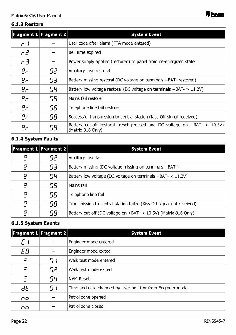
6.1.3 Restoral
Fragment 1 Fragment 2 System Event
Rq – User code after alarm (FTA mode entered)
Rw – Bell time expired
Re – Power supply applied (restored) to panel from de-energized state
.R pw Auxiliary fuse restoral
.R pe Battery missing restoral (DC voltage on terminals +BAT- restored)
.R pr Battery low voltage restoral (DC voltage on terminals +BAT- > 11.2V)
.R pt Mains fail restore
.R py Telephone line fail restore
.R pi Successful transmission to central station (Kiss Off signal received)
.R po Battery cut-off restoral (reset pressed and DC voltage on +BAT- > 10.5V) (Matrix 816 Only)
6.1.4 System Faults
Fragment 1 Fragment 2 System Event
. pw Auxiliary fuse fail
. pe Battery missing (DC voltage missing on terminals +BAT-)
. pr Battery low voltage (DC voltage on terminals +BAT- < 11.2V)
. pt Mains fail
. py Telephone line fail
. pi Transmission to central station failed (Kiss Off signal not received)
. po Battery cut-off (DC voltage on +BAT- < 10.5V) (Matrix 816 Only)
6.1.5 System Events
Fragment 1 Fragment 2 System Event
Eq – Engineer mode entered
Ep – Engineer mode exited
¥ pq Walk test mode entered
¥ pw Walk test mode exited
¥ pr NVM Reset
DT pq Time and date changed by User no. 1 or from Engineer mode
nO – Patrol zone opened
nO – Patrol zone closed
Matrix 6/816 User Manual
RINS545-7 Page 23
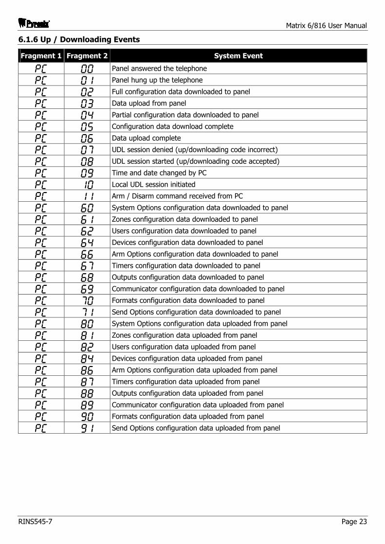
6.1.6 Up / Downloading Events
Fragment 1 Fragment 2 System Event
PC pp Panel answered the telephone
PC pq Panel hung up the telephone
PC pw Full configuration data downloaded to panel
PC pe Data upload from panel
PC pr Partial configuration data downloaded to panel
PC pt Configuration data download complete
PC py Data upload complete
PC pu UDL session denied (up/downloading code incorrect)
PC pi UDL session started (up/downloading code accepted)
PC po Time and date changed by PC
PC qp Local UDL session initiated
PC qq Arm / Disarm command received from PC
PC yp System Options configuration data downloaded to panel
PC yq Zones configuration data downloaded to panel
PC yw Users configuration data downloaded to panel
PC yr Devices configuration data downloaded to panel
PC yy Arm Options configuration data downloaded to panel
PC yu Timers configuration data downloaded to panel
PC yi Outputs configuration data downloaded to panel
PC yo Communicator configuration data downloaded to panel
PC up Formats configuration data downloaded to panel
PC uq Send Options configuration data downloaded to panel
PC ip System Options configuration data uploaded from panel
PC iq Zones configuration data uploaded from panel
PC iw Users configuration data uploaded from panel
PC ir Devices configuration data uploaded from panel
PC iy Arm Options configuration data uploaded from panel
PC iu Timers configuration data uploaded from panel
PC ii Outputs configuration data uploaded from panel
PC io Communicator configuration data uploaded from panel
PC op Formats configuration data uploaded from panel
PC oq Send Options configuration data uploaded from panel
Matrix 6/816 User Manual
Page 24 RINS545-7
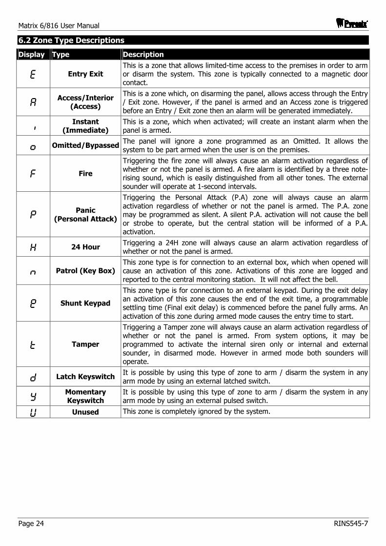
6.2 Zone Type Descriptions
Display Type Description
E Entry Exit This is a zone that allows limited-time access to the premises in order to arm or disarm the system. This zone is typically connected to a magnetic door contact.
A Access/Interior (Access)
This is a zone which, on disarming the panel, allows access through the Entry / Exit zone. However, if the panel is armed and an Access zone is triggered before an Entry / Exit zone then an alarm will be generated immediately.
I Instant (Immediate)
This is a zone, which when activated; will create an instant alarm when the panel is armed.
O Omitted/Bypassed The panel will ignore a zone programmed as an Omitted. It allows the system to be part armed when the user is on the premises.
F Fire
Triggering the fire zone will always cause an alarm activation regardless of whether or not the panel is armed. A fire alarm is identified by a three note-rising sound, which is easily distinguished from all other tones. The external sounder will operate at 1-second intervals.
P Panic (Personal Attack)
Triggering the Personal Attack (P.A) zone will always cause an alarm activation regardless of whether or not the panel is armed. The P.A. zone may be programmed as silent. A silent P.A. activation will not cause the bell or strobe to operate, but the central station will be informed of a P.A. activation.
H 24 Hour Triggering a 24H zone will always cause an alarm activation regardless of whether or not the panel is armed.
n Patrol (Key Box) This zone type is for connection to an external box, which when opened will cause an activation of this zone. Activations of this zone are logged and reported to the central monitoring station. It will not affect the bell.
¡ Shunt Keypad
This zone type is for connection to an external keypad. During the exit delay an activation of this zone causes the end of the exit time, a programmable settling time (Final exit delay) is commenced before the panel fully arms. An activation of this zone during armed mode causes the entry time to start.
T Tamper
Triggering a Tamper zone will always cause an alarm activation regardless of whether or not the panel is armed. From system options, it may be programmed to activate the internal siren only or internal and external sounder, in disarmed mode. However in armed mode both sounders will operate.
D Latch Keyswitch It is possible by using this type of zone to arm / disarm the system in any arm mode by using an external latched switch.
Y Momentary Keyswitch
It is possible by using this type of zone to arm / disarm the system in any arm mode by using an external pulsed switch.
U Unused This zone is completely ignored by the system.
Matrix 6/816 User Manual
RINS545-7 Page 25
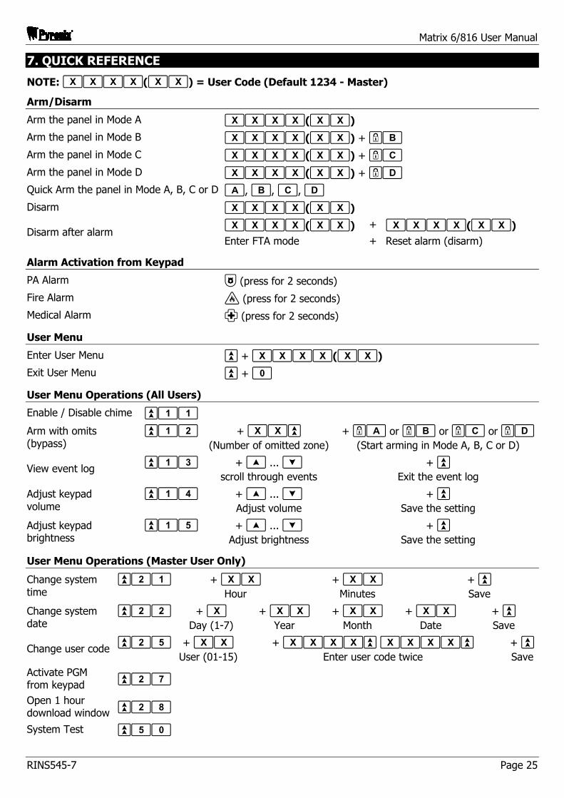
7. QUICK REFERENCE
NOTE: ffff(ff) = User Code (Default 1234 - Master)
Arm/Disarm
Arm the panel in Mode A ffff(ff) Arm the panel in Mode B ffff(ff) + -b Arm the panel in Mode C ffff(ff) + -c Arm the panel in Mode D ffff(ff) + -d Quick Arm the panel in Mode A, B, C or D a, b, c, d Disarm ffff(ff)
ffff(ff) + ffff(ff) Disarm after alarm
Enter FTA mode + Reset alarm (disarm)
Alarm Activation from Keypad
PA Alarm = (press for 2 seconds)
Fire Alarm ' (press for 2 seconds) Medical Alarm ; (press for 2 seconds)
User Menu
Enter User Menu ` + ffff(ff) Exit User Menu ` + 0
User Menu Operations (All Users)
Enable / Disable chime `11
Arm with omits (bypass)
`12 + ff` (Number of omitted zone)
+ -a or -b or -c or -d (Start arming in Mode A, B, C or D)
View event log `13 + [ ... ] scroll through events
+ ` Exit the event log
Adjust keypad volume
`14 + [ ... ] Adjust volume
+ ` Save the setting
Adjust keypad brightness
`15 + [ ... ] Adjust brightness
+ ` Save the setting
User Menu Operations (Master User Only)
Change system time
`21 + ff Hour
+ ff Minutes
+ ` Save
Change system date
`22 + f Day (1-7)
+ ff Year
+ ff Month
+ ff Date
+ ` Save
Change user code `25 + ff User (01-15)
+ ffff` ffff` Enter user code twice
+ ` Save
Activate PGM from keypad `27
Open 1 hour download window `28
System Test `50

Pyronix Limited Pyronix House Braithwell Way
Hellaby, Rotherham S66 8QY, UK
Customer Support Line (UK Only): 0900 803 7800 This is a premium rate line where calls are charged at 50p per minute (Prices correct at date of publication (02/11/2004))
Hours of business: 08:30 AM – 5:00 PM, Monday to Friday
email: [email protected]
Website: www.pyronix.com