Embed Size (px)
Citation preview

Ring-Torsion Load Cells RTB
% PTB & OIML approved as suitable for trade
use (up to 6000 d and 7500 d in case of multi-divisional scales)
% High accuracy, even for very small utilisa-
tion ranges (down to 15 % in case of trade use according to OIML)
% Low power consumption thanks to high
impedance resistance of 1100 Ω % Protection to EEx ib IIC T 6 for use in
explosion hazardous areas % Protection class IP68
Application
Acting as a transducer, the load cell converts the mechanical input signal, the load, proportionally into the electrical output voltage. The special design of the ring-torsion load cells offers particular benefits for the user:
% The extremely low headroom simplifies the use in almost all weighing applications
% The sturdy design enables easy transport, installation, and op-eration, even under harsh envi-ronmental conditions (interfering forces, or extreme tempera-tures)
Construction
% Hermetically sealed due to laser welding and glass-metal transi-tion (IP68)
% Corrosion protection due to the use of stainless steel
% All electrical components are inside the load cell and are thus optimally protected
% The high-quality, sturdy connec-tion cable is lead radially into the load cell
% Mechanically compatible with the RTK series
Functions
% High repeatability
% High long-term stability and thus continuing and consis-tently high accuracy
% Minimal effect on accuracy by side forces
% High reliability and availability, even in case of unavoidable shock loads, constraining forces or electrical interfer-ences
% Moment-free load input/output due to direct, vertical force flow
BV-D2226GB

RTB 0,13 t
RTB 0,25 t / 0,5 t
Order No.
Variants Accuracy class
C3 C3MI7,5 C6
0.13 t V041085.B01 --- ---
0.25 t V041086.B01 --- ---
0.50 t V041087.B01 V041087.B03 V041087.B06
0.25 t MR V041086.B07 --- ---
0.50 t MR V041087.B07 --- please enquire
Order No. Version ATEX II 2G; EEx ib IIC T6 / II 2D T70 °C
0.13 t V041085.B11 --- ---
0.25 t V041086.B11 --- ---
0.50 t V041087.B11 --- please enquire
Other Variants please enquire Accessories: Elastomer mount, Compact mount
Ø20+.01-.04
M5
, 8
tie
f
13.7
Ø6.5
SW 143
5
11
Ø6
3
120°
Ø5
5.5
Ø3.2
Ø6.5
35
9.5
120°
13
M10
Ø80
Ø70
Ø20+.01-.04
M6
, 8
tie
f
SW14

Technical Data
Rated capacity Emax 0,13 t 0,25 t 0,5 t
Accurate class C3 C3 C3 C3MI7.5 C6 Bezug
Sensitivity Cn 1 mV/V ±0.1 mV/V 1.75 mV/V ±0.1 mV/V 2 mV/V ±0.1 mV/V
Combined error Fcomb ±0.018 % ±0.023 % ±0.0115 % Cn
Minimum dead load output return
Fdr ±0.0167 % ±0.0167 % ±0.0066 % ±0.0083 % Cn
Creep (30 m) Fcr ±0.012 % ±0.0245 % ±0.0123 % Cn, Btn
Hysteresis ±0.017 % ±0.0167 % ±0.0083 % Cn, Btn
Temperature effect on zerosensitivity per 10K
TK0 ±0.008 %
--- ±0.014 %
±0.007 % ±0.014 %
--- ±0.009 %
±0.005 %
Cn, Btn
Option MR
Temperature effect on sensitivity per 10K
TKc ±0.008 % ±0.01 % ±0.005 % Cn, Btn
Maximum number of load cell intervals
nLC 3000 3000 6000
For multi-divisional scales: Z 7500
Minimum load cell verification interval
Vmin Emax/17500
----- Emax/10000 Emax/20000
Emax/10000 ---
Emax/15000 Emax/28000
Standard Option MR
Min. utilisation range Bamin 17 %
--- 30 % 15 %
30 % --
40 % 21 %
Emax
Option MR
Max. utilisation range Bamax 100 % Emax
Load limit * Ll 150 % Emax
Max. transverse load Lq 100 % Emax
Input resistance Re 1260 Ω ±100 Ω 1100 Ω ±50 Ω 1110 Ω ±50 Ω
Output resistance Ra 1020 Ω ±0.5 Ω 1025 Ω ±50 Ω 1025 Ω ±25 Ω
Zero signal S0 1 % 1.5 % 1 % Cn
Supply voltage Us max. 30 V (recommended): 5 V … 15 V
Nominal temperature range
Btn -10 °C … +40 °C
Service temperature range Btu -30 °C … +85 °C -30 °C … +75 °C
Storage temperature range -50 °C … +95 °C -50 °C … +80 °C
Protection class IP66 / IP68
Cable specification length of cable 5 m,
Screen insulated from housing (0.13 t), or connected to housing (0.25 t – 0.50 t)
Colour code Input + 82: pink / input - 81: grey output + 28: brown / output - 27: white
Material Stainless steel
Corrosion protection see table of Chemical resistance DDP8 483
Recommended torque for attachment bolts
8 Nm 12 – 14 Nm
ATEX-approval II 2G; EEx ib IIC T6 / II 2D T70 °C
* Permitted vibration stress to DIN 50100: 70% Emax. Peak value of stress must not exceed Emax.

BV
-D2
22
6G
B
12
13
A
ll in
form
atio
n is g
ive
n w
ith
ou
t o
blig
atio
n.
All
sp
ecific
atio
ns a
re s
ub
ject
to c
ha
ng
e.
© b
y S
ch
en
ck P
roce
ss G
mb
H,
20
12
Schenck Process GmbH Pallaswiesenstr. 100 64293 Darmstadt, Germany Phone: +49 6151 1531-1758 Fax: +49 6151 1531-3632
[email protected] www.schenckprocess.com

Ring-Torsion Load Cells RTN
% OIML approved as suitable for trade use
(up to 5000 d and 7500 d in case of multi-divisional scales)
% High accuracy, even for very small utilisa-
tion ranges (down to 15 % in case of trade use according to OIML)
% High output signal and, thus, high-
resolution of useful signal range % Low power consumption allows realisation
of multi-scale systems with simple evalua-tion electronics
% Use in hazardous zone with protection class
Ex ia IIC T4 Gb / Ex ia IIIC T125 °C Db or protection class Ex nA IIC T4 Gc / Ex tb IIIC T125 °C Db
% Protection class IP68
Application
Acting as a transducer, the load cell converts the mechanical input signal, the load, proportionally into the electrical output voltage.
The consistent optimization of the ringtorsion load cells offers additional advantages:
% The extremely low headroom simplifies the use in almost all weighing applications
% The sturdy design enables easy transport, installation, and operation, even under very harsh environmental conditions (e.g. aggressive media, inter-fering forces, or extreme tem-peratures)
Construction
% Hermetically sealed due to laser welding; protection class IP68
% High corrosion protection due to the use of electrolytically polished stainless steel
% All electrical components are inside the load cell and are thus optimally protected
% The high-quality, sturdy con-nection cable is lead radially into the load cell
% The RTN load cells are com-patible with earlier ring-torsion load cells if our adapter kits are used
Functions
% High measuring sensitivity
% High repeatability
% High long-term stability and, thus, continuing and consist-ently high accuracy
% Minimal effect on accuracy by side forces
% High reliability and availability, even in case of unavoidable shock loads, constraining forc-es or electrical interferences
% Integral excessive voltage protection
% Moment-free load input/output due to direct, vertical force flow
BV-D2019GB
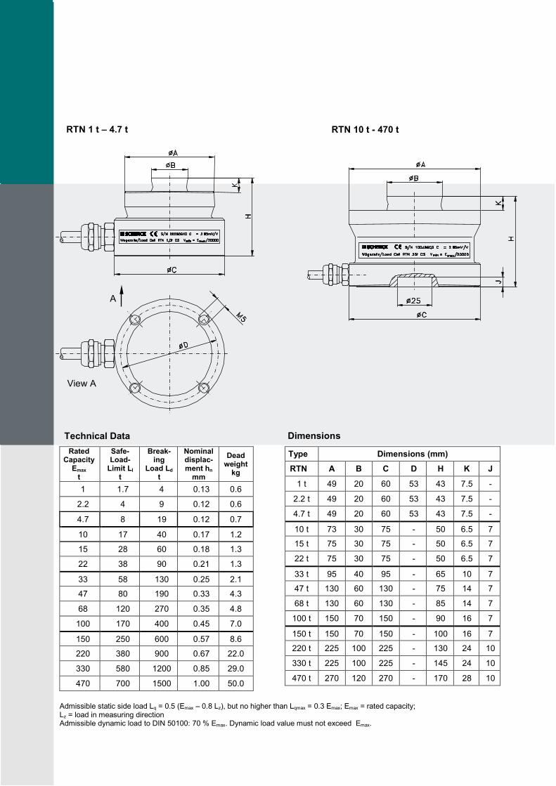
RTN 1 t – 4.7 t
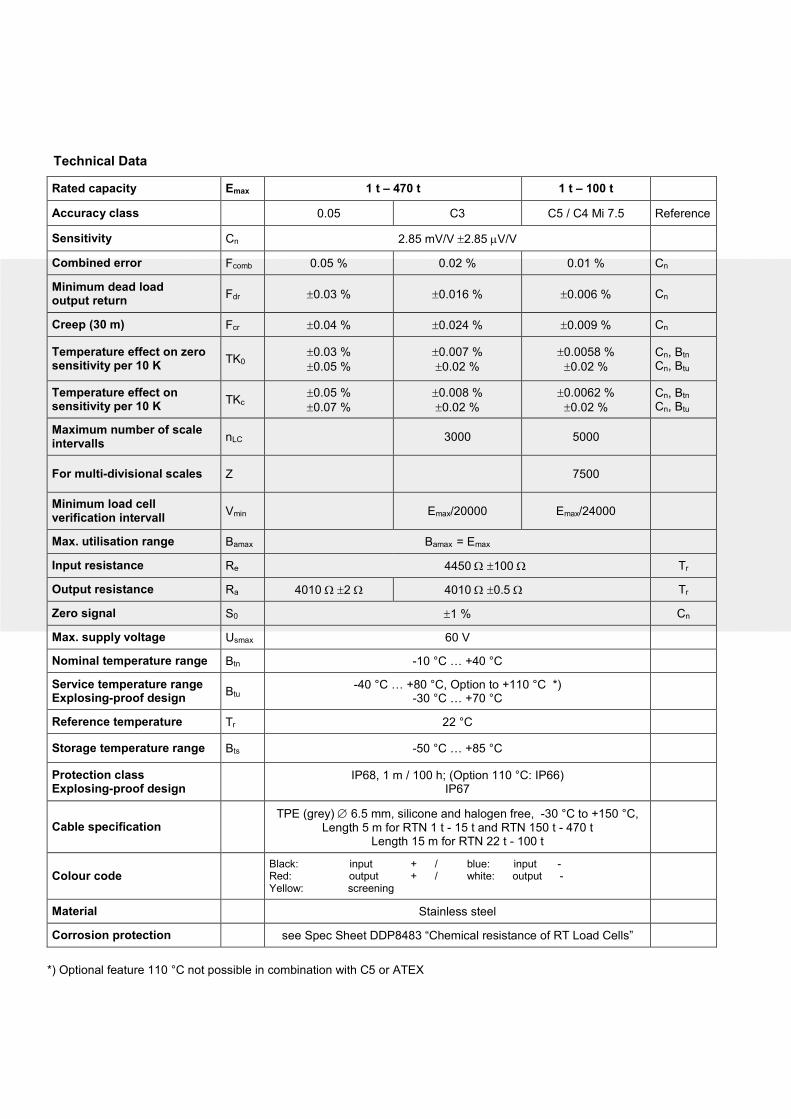
RTN 10 t - 470 t
Technical Data
Rated Capacity
Emax
t
Safe-Load-
Limit Ll
t
Break-ing
Load Ld t
Nominal displac-ment hn
mm
Dead weight
kg
1 1.7 4 0.13 0.6
2.2 4 9 0.12 0.6
4.7 8 19 0.12 0.7
10 17 40 0.17 1.2
15 28 60 0.18 1.3
22 38 90 0.21 1.3
33 58 130 0.25 2.1
47 80 190 0.33 4.3
68 120 270 0.35 4.8
100 170 400 0.45 7.0
150 250 600 0.57 8.6
220 380 900 0.67 22.0
330 580 1200 0.85 29.0
470 700 1500 1.00 50.0
Dimensions
Type Dimensions (mm)
RTN A B C D H K J
1 t 49 20 60 53 43 7.5 -
2.2 t 49 20 60 53 43 7.5 -
4.7 t 49 20 60 53 43 7.5 -
10 t 73 30 75 - 50 6.5 7
15 t 75 30 75 - 50 6.5 7
22 t 75 30 75 - 50 6.5 7
33 t 95 40 95 - 65 10 7
47 t 130 60 130 - 75 14 7
68 t 130 60 130 - 85 14 7
100 t 150 70 150 - 90 16 7
150 t 150 70 150 - 100 16 7
220 t 225 100 225 - 130 24 10
330 t 225 100 225 - 145 24 10
470 t 270 120 270 - 170 28 10
Admissible static side load Lq = 0.5 (Emax – 0.8 Lz), but no higher than Lqmax = 0.3 Emax; Emax = rated capacity; Lz = load in measuring direction Admissible dynamic load to DIN 50100: 70 % Emax. Dynamic load value must not exceed Emax.
View A
A
Technical Data
Rated capacity Emax 1 t – 470 t 1 t – 100 t
Accuracy class 0.05 C3 C5 / C4 Mi 7.5 Reference
Sensitivity Cn 2.85 mV/V ±2.85 µV/V
Combined error Fcomb 0.05 % 0.02 % 0.01 % Cn
Minimum dead load output return
Fdr ±0.03 % ±0.016 % ±0.006 % Cn
Creep (30 m) Fcr ±0.04 % ±0.024 % ±0.009 % Cn
Temperature effect on zero sensitivity per 10 K
TK0 ±0.03 %
±0.05 %
±0.007 %
±0.02 %
±0.0058 %
±0.02 %
Cn, Btn
Cn, Btu
Temperature effect on sensitivity per 10 K
TKc ±0.05 %
±0.07 %
±0.008 %
±0.02 %
±0.0062 %
±0.02 %
Cn, Btn
Cn, Btu
Maximum number of scale intervalls
nLC 3000 5000
For multi-divisional scales Z 7500
Minimum load cell verification intervall
Vmin Emax/20000 Emax/24000
Max. utilisation range Bamax Bamax = Emax
Input resistance Re 4450 Ω ±100 Ω Tr
Output resistance Ra 4010 Ω ±2 Ω 4010 Ω ±0.5 Ω Tr
Zero signal S0 ±1 % Cn
Max. supply voltage Usmax 60 V
Nominal temperature range Btn -10 °C … +40 °C
Service temperature range Explosing-proof design
Btu -40 °C … +80 °C, Option to +110 °C *)
-30 °C … +70 °C
Reference temperature Tr 22 °C
Storage temperature range Bts -50 °C … +85 °C
Protection class Explosing-proof design
IP68, 1 m / 100 h; (Option 110 °C: IP66)
IP67
Cable specification TPE (grey) ∅ 6.5 mm, silicone and halogen free, -30 °C to +150 °C,
Length 5 m for RTN 1 t - 15 t and RTN 150 t - 470 t Length 15 m for RTN 22 t - 100 t
Colour code Black: input + / blue: input - Red: output + / white: output - Yellow: screening
Material Stainless steel
Corrosion protection see Spec Sheet DDP8483 “Chemical resistance of RT Load Cells”
*) Optional feature 110 °C not possible in combination with C5 or ATEX
Order No.
Variants Accuracy class
0.05 C3 C5 / C4 Mi 7.5
RTN 1 t D726173.04 D726173.02 D726173.10
RTN 2.2 t D726174.04 D726174.02 D726174.10
RTN 4.7 t D726175.04 D726175.02 D726175.10
RTN 10 t D726176.04 D726176.02 D726176.10
RTN 15 t D726177.04 D726177.02 D726177.10
RTN 22 t D724781.04 D724781.02 D724781.10
RTN 33 t D724754.04 D724754.02 D724754.10
RTN 47 t D724782.04 D724782.02 D724782.10
RTN 68 t D724783.04 D724783.02 D724783.10
RTN 100 t D724784.04 D724784.02 D724784.10
RTN 150 t D726178.04 D726178.02
RTN 220 t D726179.04 D726179.02
RTN 330 t D726180.04 D726180.02
RTN 470 t D726181.04 D726181.02
Optional feature ATEX/IECEx approval Intrinsically safe ATEX explosion-proof design category 2GD and IECEx EPL Gb, Db Gas-Ex II 2G Ex ia IIC T4 Gb (Zone 1) Dust-Ex II 2D Ex ia IIIC T125 °C Db, IP67 (Zone 21) Warning: The verification of intrinsically safe circuit must be verified. New barriers are provided in particular for new systems. The verifications of intrinsically safe circuit are available for all load cells and barriers.
Accuracy class
0.05 2GD C3 2GD C5 / C4 MI 7,5 2GD
Variant .82 Variant .81 Variant .83
Load cells marked as intrinsically safe - Ex "i" - are also operated intrinsically safely irrespective of the zone. Non intrinsically safe ATEX explosion-proof design category 2D, 3G and IECEx EPL Db, Gc Gas-Ex II 3G Ex nA IIC T4 Gc (Zone 2) Dust-Ex II 2D Ex tb IIIC T125 °C Db, IP67 (Zone 21)
Accuracy class
0.05 2D3G C3 2D3G C5 / C4 MI 7,5 2D3G
Variant .86 Variant .85 Variant .87
Example for ordering: 47 t, accuracy class C3, ATEX category 2D, 3G. Typ RTN 47 t C3 2D, 3G …;
Order No. D724782.85
Option % Variant for service temperature range of up to 110 °C % Customized cable length % Special corrosion protection % Protection class IP69K % Cable resistant to gnawing rodents % Mounting holes
Accessories SENSiQ™ Elastomer Mount (SEM) SENSiQ™ Secure Mount (SSM) SENSiQ™ Pendulum Mount (SPM) SENSiQ™ Fixed Mount (SFM)
BV
-D2019G
B
1608.1
A
ll in
form
ation is g
iven w
ithout oblig
ation. A
ll specific
ations a
re s
ubje
ct to
change.
© b
y S
chenck P
rocess G
mbH
, 2016
Schenck Process Europe GmbH Pallaswiesenstr. 100 64293 Darmstadt, Germany Phone: +49 6151 1531 0 Fax: +49 6151 1531 66
[email protected] www.schenckprocess.com
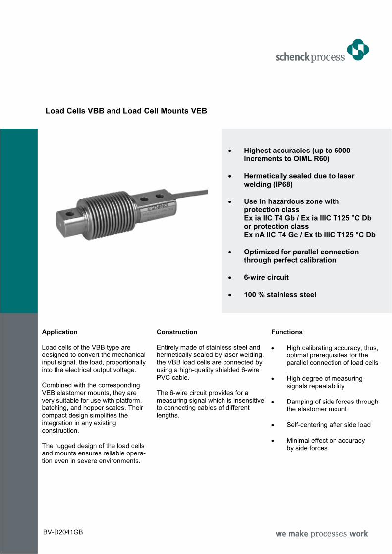
Load Cells VBB and Load Cell Mounts VEB
• Highest accuracies (up to 6000 increments to OIML R60)
• Hermetically sealed due to laser welding (IP68)
• Use in hazardous zone with protection class Ex ia IIC T4 Gb / Ex ia IIIC T125 °C Db or protection class Ex nA IIC T4 Gc / Ex tb IIIC T125 °C Db
• Optimized for parallel connection through perfect calibration
• 6-wire circuit
• 100 % stainless steel
Application Load cells of the VBB type are designed to convert the mechanical input signal, the load, proportionally into the electrical output voltage. Combined with the corresponding VEB elastomer mounts, they are very suitable for use with platform, batching, and hopper scales. Their compact design simplifies the integration in any existing construction. The rugged design of the load cells and mounts ensures reliable opera-tion even in severe environments.
Construction Entirely made of stainless steel and hermetically sealed by laser welding, the VBB load cells are connected by using a high-quality shielded 6-wire PVC cable. The 6-wire circuit provides for a measuring signal which is insensitive to connecting cables of different lengths.
Functions
• High calibrating accuracy, thus, optimal prerequisites for the parallel connection of load cells
• High degree of measuring signals repeatability
• Damping of side forces through the elastomer mount
• Self-centering after side load
• Minimal effect on accuracy by side forces
BV-D2041GB

VBB Load Cells 5 kg – 0.5 t
Variant Dimensions (mm)
А В
VBB 5 kg – 0.2 t 8.2 8.2
VBB 0.5 t 10.5 11.1
VEB Elastomer Mount 5 kg – 0.5 t for VBB Load Cells Capacities 5 kg – 0.2 t Capacity 0.5 t
Elastomer mount correct mounting position
Dimensions (mm)
Elastomer mount A B C D E F G H K L M N P R FR* Smax**
VEB 5 kg – 0.2 t 75 M12 12 40 79 ±1,3 18.5 M8 SW 17 19 - - - - - 163 3
VEB 0.5 t 80 M10 10 39 26 - SW 27 - 20 120 100 9 60 400 4.5
* FR Restoring force in N with 1 mm lateral displacement ** Smax., in mm, maximum adm. lateral displacement if loaded with rated capacity
Fixation Load input
Shielded 6-wire cable, shield on housing
Metal bellows
Screws offset by 35
0

Technical Data
Rated capacity Emax 5 kg – 0.5 t
Accuracy class D1 C3* C4** C6*** Reference
Nominal characteristic value Cn 2 mV/V +20 μV/V;
-2 μV/V 2 mV/V ±1 μV/V
Combined error Fcomb 0.05 % 0.02 % 0.013 % 0.01 % Cn
Zero signal return after loading (30 min)
Fdr ±0.049 % ±0.016 % ±0.012 % ±0.008 % Cn
Creep error during stress (30 min)
Fcr ±0.049 % ±0.016 % ±0.012 % ±0.008 % Cn
Temperature coefficient of zero signal
TK0 ±0.05 %/10 K ±0.0125 %/10 K ±0.009 %/10 K ±0.009 %/10 K Cn в Вtn
Temperature coefficient of characteristic value
TKc ±0.05 %/10 K ±0.008 %/10 K ±0.007 %/10 K ±0.004 %/10 K Cn в Вtn
Maximum number of increments in certified applications
nLC 1000 3000 4000 6000
Min. scale interval vmin 0.036 % 0.009 % 0.0066 % 0.0066 % Еmax
Minimum utilisation rate Bamin 36 % 27 % 26 % 39 % Еmax
Maximum utilisation rate Bamax Bamax = Emax
Input resistance Re 350 Ω - 480 Ω tr
Output resistance Ra 356 Ω ±0.2 Ω 356 Ω ±0.12 Ω tr
Zero signal S0 ±1 % Cn
Maximum supply voltage Usmax 18 V
Nominal temperature range Btn -10 °C … +40 °C
Service temperature range Explosion-proof design
Btu -40 °C … +70 °C -30 °C … +70 °C
Reference temperature tr 23 °C
Storage temperature range Bts -50 °C … +85 °C
Safe load limit EL 150 % Cn
Breaking load ED 300 % Cn
Displacement **** at rated capacity
0.25 mm 0.3 mm 0.4 mm 0.6 mm
5 kg 10 - 100 kg 200 kg 500 kg
Protection class Explosion-proof design
IP68 (tightened test conditions: 1 m water gauge; 100 h)
IP67
Cable specification 3 m PVC cable, 6 wires, shielded, shield on housing
Colour code black: input - / blue : input + / black/yellow: shield red : output - / white : output + grey : sensor - / green : sensor +
Corrosion protection Stainless steel
*: Quality C3 available for nominal loads > 10 kg only **: Quality C4 available for nominal loads > 20 kg only ***: Quality C6 available for nominal loads > 50 kg only
****: Please adjust the overload stops to nominal displacement +0.05 mm (unloaded scale)
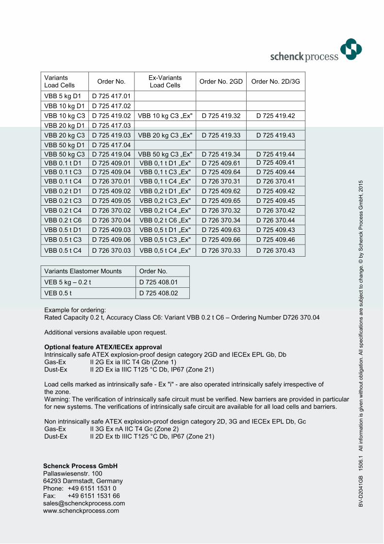
Variants Load Cells
Order No. Ex-Variants Load Cells
Order No. 2GD Order No. 2D/3G
VBB 5 kg D1 D 725 417.01
VBB 10 kg D1 D 725 417.02
VBB 10 kg СЗ D 725 419.02 VBB 10 kg СЗ „Ex" D 725 419.32 D 725 419.42
VBB 20 kg D1 D 725 417.03
VBB 20 kg C3 D 725 419.03 VBB 20 kg C3 „Ex" D 725 419.33 D 725 419.43
VBB 50 kg D1 D 725 417.04
VBB 50 kg C3 D 725 419.04 VBB 50 kg C3 „Ex" D 725 419.34 D 725 419.44
VBB 0.1 t D1 D 725 409.01 VBB 0,1 t D1 „Ex" D 725 409.61 D 725 409.41
VBB 0.1 t C3 D 725 409.04 VBB 0,1 t C3 „Ex" D 725 409.64 D 725 409.44
VBB 0.1 t C4 D 726 370.01 VBB 0,1 t C4 „Ex" D 726 370.31 D 726 370.41
VBB 0.2 t D1 D 725 409.02 VBB 0,2 t D1 „Ex" D 725 409.62 D 725 409.42
VBB 0.2 t C3 D 725 409.05 VBB 0,2 t C3 „Ex" D 725 409.65 D 725 409.45
VBB 0.2 t C4 D 726 370.02 VBB 0,2 t C4 „Ex" D 726 370.32 D 726 370.42
VBB 0.2 t C6 D 726 370.04 VBB 0,2 t C6 „Ex" D 726 370.34 D 726 370.44
VBB 0.5 t D1 D 725 409.03 VBB 0,5 t D1 „Ex" D 725 409.63 D 725 409.43
VBB 0.5 t C3 D 725 409.06 VBB 0,5 t C3 „Ex" D 725 409.66 D 725 409.46
VBB 0.5 t C4 D 726 370.03 VBB 0,5 t C4 „Ex" D 726 370.33 D 726 370.43
Variants Elastomer Mounts Order No.
VEB 5 kg – 0.2 t D 725 408.01
VEB 0.5 t D 725 408.02
Example for ordering: Rated Capacity 0.2 t, Accuracy Class C6: Variant VBB 0.2 t C6 – Ordering Number D726 370.04 Additional versions available upon request. Optional feature ATEX/IECEx approval Intrinsically safe ATEX explosion-proof design category 2GD and IECEx EPL Gb, Db Gas-Ex II 2G Ex ia IIC T4 Gb (Zone 1) Dust-Ex II 2D Ex ia IIIC T125 °C Db, IP67 (Zone 21) Load cells marked as intrinsically safe - Ex "i" - are also operated intrinsically safely irrespective of the zone. Warning: The verification of intrinsically safe circuit must be verified. New barriers are provided in particular for new systems. The verifications of intrinsically safe circuit are available for all load cells and barriers. Non intrinsically safe ATEX explosion-proof design category 2D, 3G and IECEx EPL Db, Gc Gas-Ex II 3G Ex nA IIC T4 Gc (Zone 2) Dust-Ex II 2D Ex tb IIIC T125 °C Db, IP67 (Zone 21)
Schenck Process GmbH Pallaswiesenstr. 100 64293 Darmstadt, Germany Phone: +49 6151 1531 0 Fax: +49 6151 1531 66 [email protected] www.schenckprocess.com
BV
-D2041G
B
1506.1
A
ll in
form
ation is g
iven w
ithout oblig
ation. A
ll specific
ations a
re s
ubje
ct to
change. ©
by S
chenck P
rocess G
mbH
, 2015
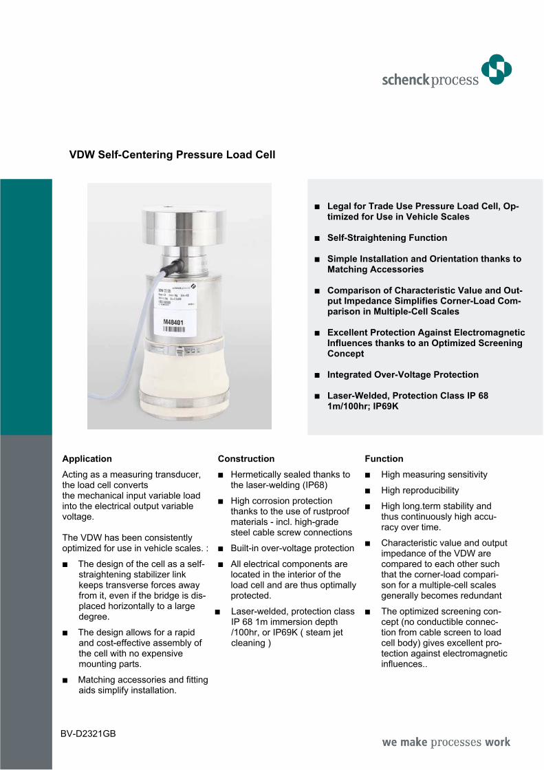
VDW Self-Centering Pressure Load Cell
% Legal for Trade Use Pressure Load Cell, Op-
timized for Use in Vehicle Scales % Self-Straightening Function % Simple Installation and Orientation thanks to
Matching Accessories % Comparison of Characteristic Value and Out-
put Impedance Simplifies Corner-Load Com-parison in Multiple-Cell Scales
% Excellent Protection Against Electromagnetic
Influences thanks to an Optimized Screening Concept
% Integrated Over-Voltage Protection % Laser-Welded, Protection Class IP 68
1m/100hr; IP69K
Application
Acting as a measuring transducer, the load cell converts the mechanical input variable load into the electrical output variable voltage. The VDW has been consistently optimized for use in vehicle scales. :
% The design of the cell as a self-straightening stabilizer link keeps transverse forces away from it, even if the bridge is dis-placed horizontally to a large degree.
% The design allows for a rapid and cost-effective assembly of the cell with no expensive mounting parts.
% Matching accessories and fitting aids simplify installation.
Construction
% Hermetically sealed thanks to the laser-welding (IP68)
% High corrosion protection thanks to the use of rustproof materials - incl. high-grade steel cable screw connections
% Built-in over-voltage protection
% All electrical components are located in the interior of the load cell and are thus optimally protected.
% Laser-welded, protection class IP 68 1m immersion depth /100hr, or IP69K ( steam jet cleaning )
Function
% High measuring sensitivity
% High reproducibility
% High long.term stability and thus continuously high accu-racy over time.
% Characteristic value and output impedance of the VDW are compared to each other such that the corner-load compari-son for a multiple-cell scales generally becomes redundant
% The optimized screening con-cept (no conductible connec-tion from cable screen to load cell body) gives excellent pro-tection against electromagnetic influences..
BV-D2321GB