Embed Size (px)
Citation preview

15-RUG-2008 10:19R FR0M:PSR GROUP LONDON KY 859-402-2735 T0:12026939441 P .2/22
Suggestions submitted on 8/15/08 to the MSHA Committee in relationship to the RIN 12 1 9-AB5 8
These suggestions are in relationship to the mine refuge.
1. A suggestion in relationship to the square footage and cubic footage. (Page S 1 through S4)
2. A suggestion in relationship to a cooling system and C02 removal system. (Page S5 through S 12)
3. A suggestion on connecting the mine refuge to a borehole in the mine. (Page S 13 through S 16)
4. A suggestion on the physical placement and capability of having a fully current emergency escape route on the front of the mine refuge unit. (Page S 17 through S 18)
5. A suggestion on a cylinder storage area featuring a silica cloth firewall separating the cylinders fiorn the mine refuge living chamber. (Page S 19 through S20)

15-RUG-2008 10:19R FR0M:PSR GROUP LONDON KY 859-402-2735
MSHA Mining Committee
Outlined on the following pages are suggestions that we would like to make - - - h - ~ : l ~ i m s h i p - ~ t h m ~ r ~ - s q a m ~ f o & ~ r m e n ~ ;
the proposal states that 15 square feet and 60 cubic feet must be required inside a mine rescue chamber for each individual miner. Our unit, by virtue of its modular design states that we believe it would very easily be possible for individuals to reside comfortably inside the rescue chamber with less square footage and less cubic footage in an emergency situation.
Shown in photograph 1 are 4 of our largest employees whom we photographed standing next to our 48" tall mine refuge for the purpose of scale.
Beginning from left to right they are as follows: 6' tall and weighs 185 pounds 6' 1 ", weighs 235 pounds 6'2", weighs 220 pounds 6', weighs 275 pounds
We believe that this is a very good reference to larger sized individuals.
15-RUG-2008 10:20R FR0M:PSR GROUP LONDON KY 859-402-2735
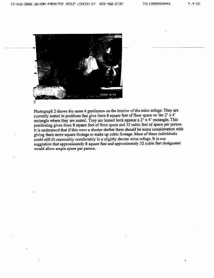
Photograph 2 shows the same 4 gentlemen on the interior of the mine refuge. They are currently seated in positions that give them 8 square feet of floor space on the 2' x 4' rectangle where they are seated. They are leaned back against a 2' x 4' rectangle. This positioning gives them 8 square feet of floor space and 32 cubic feet of space per person. It is understood that if this were a shorter shelter there should be some consideration with giving them more square footage to make up cubic footage. Most of these individuals could still fit reasonably comfortably in a slightly shorter mine refuge. It is our suggestion that approximately 8 square feet and approximately 32 cubic feet designated would allow ample space per person.
15-RUG-2008 18:20fl FR0M:PSR GROUP LONDON KY 859-402-2735
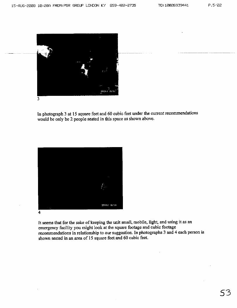
In photograph 3 at 15 square feet and 60 cubic feet under the current recommendations would be only be 2 people seated in this space as shown above.
I t seems that for the sake of keeping the unit small, mobile, light, and using it as an emergency facility you might look at the square footage and cubic footage recommendations in relationship to our suggestion. In photographs 3 and 4 each person is shown seated in an area of 15 square feet and 60 cubic feet.
15-QUG-2888 10:28R FR0M:PSR GROUP LONDON KY 859-482-2735
If there is a review of the square footage and cubic footage of this unit we would like to suggest that an air lock capable of having a standard stretcher pass through it in a way that allows the air lock to have the air changed with a stretcher in it as well as the air lock feature as it is currently outlined in the recbendations. It seems to be a very large - amount of space. It is assumed that the air lock would have to be at least 6' long to make function as stated in the regulations.
We are currently working on a system that will allow the possible movement of individuals between areas with a very minimal risk of contamination. We would suggesl that while looking at square footage and cubic footage considerations, that as long as there are provisions for preventing contamination in the living chamber and reducing the risk of potential contamination that the air lock have the potential to be made much smaller. It is still assumed that contamination would need to be minimized while allowing a stretcher or individuals to move through these areas. We are finishing work on a seal that addresses this and would allow the availability for more living space while minimizing the size and amount of air required to utilize the air lock.
1 5 - R U G - 2 0 0 8 1 0 : 2 1 R FR0M:PSR GROUP LONDON KY 859-402-2735
15-RUG-2008 10:21R FR0M:PSR GROUP LONDON KY 859-402-2735
Cooling Air Conditioning System This system is designed to run off 12Volts DC. There are 2 to 4 large deep cycle batteries each approximately the size of a conventional automobile
- - 4 m ~ ~ ~ ~ ~ ~ 3 5 4 n n l l n r 1 4 ~ ~ ~ d e
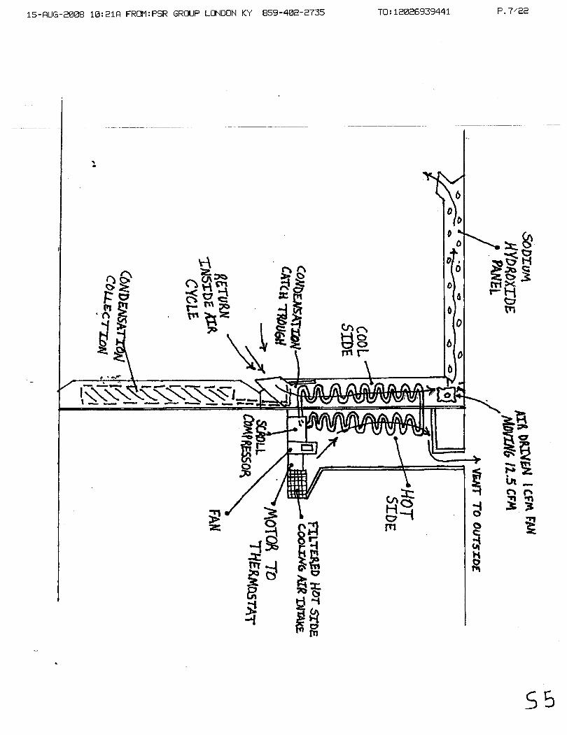
up of sealed gel type batteries that can be charged and put into place. We are anticipating being able to get a 6-month life out of these batteries at least. When they drop down they need to be recharged and put back in place. The air conditioning unit has an enclosed explosion proof motor that operates a scroll type compressor. The compressor operates a unit similar to an automobile air conditioner or an airplane. In our application the air conditioner has the cooling side completely separated fiom the compressor side so that there is no air movement between the two. The cooling side of the unit allows air to move from the interior of the unit past a circulating fan operating off the same explosion proof motor to move air throughout the unit while allowing the compressor to kick on and off as needed by virtue of a thermostat. The cool side of the unit located on the inside of the Mine Shield also acts as a dehumidifier and condenser. Moisture that condenses and drips off is drained and trapped in 2 units located in the panels in fiont of the air conditioning unit on the floor. The air conditioning unit's flow through of air can be directed into the sodium hydroxide units if C02 mitigation is necessary or simply allowed to circulate dependent upon the amount of C02 in the environment. It is assumed that upon entering one will begin to scrub out C02 almost immediately therefore it will be designed to put a sodium hydroxide panel opened in the path of flow as soon as the unit is activated. The ability for it to absorb C02 at a vary of different rates allows that it will then be able to absorb small portions of C02 through the life of the unit. It may be easier to begin absorbing small units of C02 over time than to let the C02 concentration build up. This will mitigate any issues that we might have with the range of the C02 detector; we happen to know that we are removing C02 from the environment before it could build up. The fan on the interior that moves the cooling air and on the exterior that blows air across the heated coils for the purpose of giving a heat exchange are considered to be an extension of the explosion proof motor simply pushing hot air away fiom the exterior and allow the cool air to be circulated on the interior. This is very similar to an automobile application or window unit in a home as long as it is realized that there is no air transfer between the exterior and the interior. The return on this application will be located on the lower portion of the sidewall. It will bring the air into the lower portion of the air conditioning panel, circulate the air past the cooling fins, and press it out through the top most likely through the C02 scrubber.
15-RUG-2008 10:22R FR0M:PSR GROUP LONDON KY 859-402-2735
Mine Shield
White paper on air-conditioning system/ ELECT R I L hk - -- p,.- 6S$i---- - - - --- - -- ---- . --- - -- -- - - -
Description of the function of the air conditioning system
One panel, possibly two, will be designed so that thc standard and known cooling portions of a regular air conditioner extend through the side of the interior. There is no air movement between the two but the cooling loops extend into the interior of the panel. The heat exchange portion of the air conditioner is located on the opposite side of as well as an explosion proof motor and a scroll type compressor that allows the unit to finction. There are several different manufacturers who make these and they are primarily being used in the aircraft industry. The motor is explosion proof. The heat exchange blower is spark proof also. This unit at 5,000 -10,000 BTUs is capable of running for 4 days on a reasonably large bank of sealed gel batteries operating at 12 Volts DC. Once the gel takes a charge is capable of holding the charge for an extensive period of time past 60 days without any difficulties. Ultimately it can periodically be recharged or topped off by bringing another 12 Volt battery into position to charge. There is no hydrogen generation from the charging of a sealed gel battery, which makes this process inherently safe. The electrical unit for the air conditioning will have a shaft extension located on the interior off of the sealed explosion proof DC motor that runs the compressor which runs the interior fan unit to provide the necessary 12.5 cubic feet of air that blows through the unit to keep air circulation up. These air conditioning units will be placed in the back of the unit. Directly below them in the floor are the catch basins that will take the moisture that condenses off of the cold portion, drips downward into a catch tray, and is then fed and stored below the trays. The sodium hydroxide panels will be located in the ceiling above so that when a sodium hydroxide panel is pulled down the peeled off seal strips are pulled off, it is hung in position, the air movement from the blower located with the air conditioning portion will blow the column of air up, push it through the sodium hydroxide allowing it to scrub out the C02. This will provide the sodium hydroxide with a stream of cool dehumidified air to allow it to remove the carbon dioxide from that air stream. The current electrical analysis shows that this will run in excess of 100 hours with a Fully charged set of batteries with the current technology that we have. We are looking at a couple of battery styles that increase that output and allow the battery pack, if in need of service, to be pulled out and the battery replaced. The batteries would have a reasonably small footprint and weigh 250-300 pounds combined. The ability to carry in an additional battery and top off the existing battery as in a trickle charge application is currently being reviewed. This would eliminate the need to have electricity run to this unit for any other reason than periodic maintenance and checking. A gauge in front of the unit would show the current available for inspection. At full charge this battery pack would show 12.7 Volts. Any drop off of this would show a need to recharge. The technology is "pretty much existing". It is going to use FREON or a similar material. We have a group currently finishing up the OEM product and guaranteeing it to be explosion proof as well as the life and durability that we need on this unit. It should be stipulated that once the unit has been run for 96 hours in this environment it will be pulled, check

15-RUG-2008 10 :22R FR0M:PSR GROUP LONDON KY 859-402-2735
and refurbished if necessary. This bank of batteries can be constantly monitored. As long as it does not fall off 12.7 Volts there is not a situation. The life on the sealed gel batteries is very good and the recharge and draw down on them is very good. They are not horribly expensive costing approximately 25% more than a standard lead acid battery, they are
-
commoniy a v a ~ S i G i f i i i i ~ are u s e m m ~ i - a p ~ ~ e ~ e p --
cycle trolling type batteries are needed. If you needed 1 cooling units for a small unit you could add 2 for a larger unit and so on giving you redundancy and build out. The units we are looking at run between 5,000 and 10,000 BTUs. The air conditioning unit could be carried under 1 arm. It is very small, light and compact due to their primary use in the aircraft industry currently.

15-RUG-2088 10:23Q FR0M:PSR GROUP LONDON KY 859-402-2735 T0:12026939441
Mine Shield
White paper on Electrical Requirements - -Proje&--f63$ ---- -- - - -- --- -- - -- -- -- -
When we put in the 12 Volt air conditioning unit across the 96 hour block and opted to go with the explosion proof DC motor and the coil type compressor we found that we had some energy needs in relationship to the diagnostic panels as well as lighting and a couple of other very low impact items. The figure drawn with the electrical panels shows 3 batteries, these are 12 Volt systems. Each battery provides 2.6 Amps at 100 hours at 160 pounds each with a dimension of 20.75 x 11 x 10. These 3 batteries connected together generate 7.95 Amps over 100 hours. They are sealed gel batteries. The white paper on air conditioning systems/electrical goes into great detail about the size, shape and voltage requirements of this. The sealed gel battery company is recommending that we get 4-6 month life without any trickle down problems. When trickle down problems occur, carrying of a standard automobile battery for use as a trickle charge battery for the units on site without them having to be connected allows that if a trickle down voltage problem occurred a service battery attached to it would immediately give at least its minimum life and to charge the battery pack as a remote system and allow it to maintain. Though the batteries are heavy they would allow plenty of energy for this situation for all the electrical needs for 100 hours.

15-RUG-2008 10 :23R FR0M:PSR GROUP LONDON KY - - - I - p u

15-QUG-2008 18:23Q FR0M:PSR GROUP LONDON KY 859-402-2735 TO : 12826939441 P. 13/22

15-RUG-2008 10:24R FR0M:PSR GROUP LONDON KY 859-402-2735
Verbage to accompany the air metering drawing
The cylinders are shown in the lower portion. This can be compressed air or -- - - ~ & e 2 - M - l & ~ o m d d i t i o n a l - f i I t e r -beds-but few
to be working off of compressed air. The compressed air cylinders are connected by a standard line and opened by the hand wheel to the central manifold. The central manifold from a compressed air cylinder drives continuously. The air fan motor shown in the upper portion of the duct work is designed to move 12.5 cubic feet of air per minute for the purpose of providing circulation as well as providing movement of air through the sodium hydroxide scrubber seen in the upper portion. The line (for the 02 for the air fan motor) is routed through the cooling loops on the air conditioning side to assist in cooling them due to the fact that by releasing this gas under pressure through this line, the line will become chilled and help the air conditioner unit be more effective. The central manifold also contains an 02 sensor to a switch. The 02 sensor that is in line with the constantly moving stream of air allows that if the 02 sensor detects a lack of required oxygen it opens the 02 vent, which is also threaded through the cooling coils for the purpose of allowing the expanding gas fiom it to provide a chilling effect also. The cylinders are contained in the back portion of the unit allowing the compressed air, or possibly compressed oxygen, along with correct metering and mixing capacity to be introduced to the interior of the chamber.

15-RUG-2008 10:24fl FR0M:PSR GROUP LONDON KY 859-402-2735

15-RUG-2008 10:24R FR0M:PSR GROUP LONDON KY 859 -402 -2735

15-AUG-2008 10:24A FR0M:PSR GROUP LONDON KY 859-402-2735
Description
--T-htGborekol e mnneetter forair ifdesig~e&ina&ha-way that-should-a- - -- borehole be sunk or this located near a borehole one could go up to a borehole very quickly, plug this in, turn the hand wheel until the plug expands thereby sealing it in place, take the other end of the hose, remove 1 cap from a panel on the rescue chamber, screw it into the side panel and allow air to be blown under pressure through there. There is also a gate valve that would allow reduction of flow into the rescue chamber since the amount being pumped from the surface could be excessive and could pressurize and move a lot of air through there. You can down play it a little bit so that they know that you are getting air but there are no obstructions.
15-RUG-2008 10:25f1 FR0M:PSR GROUP LONDON KY 859-402-2735
Borehole Connector
Abstract - - -- - - - - --
The borehole connector is a unit that allows a safety rehge chamber used in mining or other underground industries to be conveniently connected to a hole that has been drilled down through the earth for the purpose of connecting air supply, communication signals, or other items to be communicated through the pipe. The borehole connector is designed so that a stored flexible piece of tubing can be quickly connected to the refuge chamber. The opposite end can be connected to a wide variety of diameters of piping used in the drilling industg that allows the open area of the borehole to be connected £kom the surface and possibly surface air circulating systems to the refuge chamber below the earth.

10:25R FROMEPSR GROUP LONDON KY 859-402-2735

15-RUG-2008 10:25R FR0M:PSR GROUP LONDON KY 859-402-2735
Emergency Route & Escape Feature A closed steel box will be located on the fiont as shown in the drawings. It
--wiJl-c~bin~c~d~&&-$uratrle-~rialthatalloursa map-toh- - _ ___-
placed in between and then sealed. On the fiont of the placard a magic marker can be used to show the route of egress. If teams were seni looking for escape routes, distances from the surface, exact location, etc. all of this information would be loaded onto the placard. This would allow the placard to be modified to show the location of the rescue chamber when the unit is moved. This information could be translated to the map on the surface and added to the emergency response plan. There was a concern that when a unit is moved the crew moving it should log the area but if an event occurred before that, no one would know exactly where the unit was located. It was emphasized that this would be of assistance during an emergency situation when individuals are easily conbsed and disoriented.

15-QUG-2008 10:25f4 FR0M:PSR GROUP LONDON KY 859-402-2735
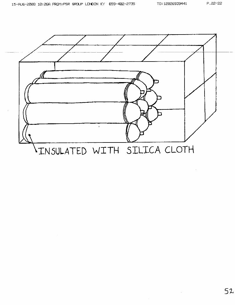
Cylinder Storage Area Featuring 3,000 degree Silica Cloth Firewall The cylinder storage area added to one end of the "sled" is broken up in 24" wide blocks dependent upon the number of cylinders to be carried. An
- - u ~ r ~ o s ~ ~ ~ ~ t k e F Q 1 1 ~ ~ e ~ ~ - t k i s s ~ ~ ~ t T h e standard panels are used around the exterior to protect the cylinder storage area fiom debris or damage. Contained inside the cylinder storage area is the cylinder, necessary regulators to transfer the gas fiom the cylinders, and an access port that allows it to be opened conveniently when it is necessary to check the cylinders or the air conditioning unit. Attached with this is a drawing showing 3,000 degree silica cloth being used as a firewall in between the living chamber and the cylinder storage area. There are several systems that can fit into the cylinder storage area and the ability to have a flexible high temperature firewall in between them is self-evident.
1 5 - R U G - 2 0 0 8 1 0 : 2 6 Q FR0M:PSR GROUP LONDON KY 859-402-2735
15-QUG-2008 10:19Q FROMLPSR GROUP LONDON KY 859-402-2735
P.0. Box 1783 Mt. Vernon, KY 40456
Urgent Reply ASAP Please comment Please review
Total pages, including cover sheet:
Send to: MSCIA, ~ L C & -4 ~ r o m
For your information
&ms, and \a~i&u\ces ~ttgntion:
R N ~19- A858 Fax number:
202 - 673 i3-9qq1
Date: 5 A y ~ s # 2 ~ g .
Phone numbex! 606-256-0962


![Smells Like Teen Spirit Rock Ab5 [5] [9] Ab5 [13] Let ring](https://img.pdfslide.us/doc/110x75/6209584109aba263cf74abdf/smells-like-teen-spirit-rock-ab5-5-9-ab5-13-let-ring-.jpg)