Embed Size (px)
Citation preview

Anthony Hardwood Composites
emtekH E A V Y E Q U I P M E N T M A T
RIGMAT DESIGN GUIDE
TM

emtekrigmat
H E A V Y E Q U I P M E N T M A T
TM
emtek rigmat is the engineeredmat for enabling heavy equipmentto operate on unstable or softsoil conditions.
Excavators
Pipe Layers
Loaders
Drilling Rigs
TABLE OF CONTENTS
Introduction . . . . . . . . . . . . . . . . . . . . . . . . . . . . . . . . . . . . . . . . . . . . . . . . . . . . . . . . . . . . . . . . . . . . .1
Storage & Handling . . . . . . . . . . . . . . . . . . . . . . . . . . . . . . . . . . . . . . . . . . . . . . . . . . . . . . . . .1
How to Use This Guide . . . . . . . . . . . . . . . . . . . . . . . . . . . . . . . . . . . . . . . . . . . . . . . . . . . . . . . . . . . .2
Caution to Users . . . . . . . . . . . . . . . . . . . . . . . . . . . . . . . . . . . . . . . . . . . . . . . . . . . . . . . . . . .2
emtek rigmat Specifications . . . . . . . . . . . . . . . . . . . . . . . . . . . . . . . . . . . . . . . . . . . . . . . . . . . . . . .3
Comparison . . . . . . . . . . . . . . . . . . . . . . . . . . . . . . . . . . . . . . . . . . . . . . . . . . . . . . . . . . . . . . .3
Weight Table . . . . . . . . . . . . . . . . . . . . . . . . . . . . . . . . . . . . . . . . . . . . . . . . . . . . . . . . . . . . . . .3
Uniform Bearing On Soil
Load Diagrams . . . . . . . . . . . . . . . . . . . . . . . . . . . . . . . . . . . . . . . . . . . . . . . . . . . . . . . . . . . . . .4
Table I, Load Criteria (centered loading) Load Case 1, 2, 3 . . . . . . . . . . . . . . . . . . . . . . . . . . .5
Table II, Load Criteria (offset loading) Load Case 4, 5, 6 . . . . . . . . . . . . . . . . . . . . . . . . . . . . .6
Notes for Table I & II, Determining Loads . . . . . . . . . . . . . . . . . . . . . . . . . . . . . . . . . . . . . . . .7
Design Properties . . . . . . . . . . . . . . . . . . . . . . . . . . . . . . . . . . . . . . . . . . . . . . . . . . . . . . . . . . . . . . . .7

1
emte
k rig
mat
mat
s
Ant
hony
Har
dwoo
d C
ompo
sites
Anthony Hardwood Composites
This Design Guide is intended to provide design information to enable you to
determine how emtek rigmat can best serve your needs. Anthony
Hardwood Composites’ emtek rigmat is an engineered, laminated
wood mat that is made from indigenous Southern hardwoods in
Sheridan, Arkansas and then framed with a 1/2" wall formed
channel. By protecting the emtek core from handling
abuse, the emtek rigmat will provide longer and
more consistent usable mat life.
Durability
emtek rigmat is engineered to withstand the abuse of today's industrial construction sites. Control of raw material density in
the manufacturing process ensures that emtek rigmat has a hard, impact resistant surface. The laminating process creates a
composite structure that resists fracture.
Strength
Predictable, reliable strength is a necessity when the safety of workers and equipment assets are at stake. Patented construction
creates a work platform that has engineering design values that exceed all sawn woods identified by the National Design
Standard (NDS 2004). Every emtek rigmat component is proof loaded by machine to ensure that the finished mat will meet
the strict design criteria and quality standards established by AHC.
Consistency
Uniform product dimensions with a consistent finish create a work surface that helps contractors reduce workplace hazards.
Storage and Work Environment Considerations
emtek rigmat mats are valuable to the contractor, and proper storage can extend the service life for many years. Product
should be stored in an environment with good drainage. Stacking mats with stickers between layers provides an avenue for
air movement that can reduce the effects of decay caused by prolonged exposure to moisture.
Wood is a natural polymer that exhibits good resistance to chemical exposure; however, extended contact with strong acids
(ph<3) or strong bases (ph>9) can cause wood to degrade and compromise the structural integrity of the product. The resins
used in emtek rigmat construction are thermoset polymers that are highly resistant to chemical attack and will degrade
slower than the wood when exposed to high chemical concentrations. Chemical MSDS sheets should be referenced if the
product’s exposure is suspected.
Prolonged exposure to temperature above 150o F can cause the wood to degrade and should be avoided to ensure that the
product performs at the designed levels.
Introduction

2
emtek rigm
atm
ats Anthony H
ardwood C
omposites
How to use this guide…
emtek rigmat mats are essentially our standard emtek mat framed with steel for added durability. Like ourstandard emtek mats these are engineered to support specified loads. The tables in this guide show allowableloads. These loads are based solely on the strength of the emtek billets within the frame. No strength hasbeen associated with the steel frame in the following allowable load tables. This is because the distancebetween steel members is too great to assume that loads can be effectively transferred from one steelmember to the next with a moving load. Each mat has been proof loaded to 1.5 times the allowable load atthe manufacturing facility to certify these values.
The following pages show different loading configurations for the mats. Mat thickness is actually 1/2" greaterthan the indicated size. This is because machining the emtek billets to accept the steel and create a flush surfaceresults in an affective loss of material of 1/2". Generally pneumatic tired vehicles will be represented by the 6'wide loading configurations (Load Case 1 and Load Case 4). Tracked vehicles will generally be represented bythe 9' wide loading configurations (Load Case 2 and Load Case 5). When one wheel or track is on one mat,the single load configurations shown in Load Case 3 and Load Case 6 will be applicable. In all cases the loadsshown in the tables are in thousands of pounds (Kips). To get pounds simply multiply the number in the cellby 1000.
It is important to note that the loads are associated with one foot of mat width. If the footprint of the tire is2' long then the allowable load can be multiplied by two. This is especially important when considering appli-cations for tracked vehicles that can distribute loads along track lengths up to16' or longer.
There are two sets of tables. The first set is for applications where load is centered on the mat. The secondset (Table 2) is for applications where the load is offcenter. In the applications of Uniform Bearing, we haveshown different allowable loads for different soil conditions (Soil Type "1", "3", and "5"). These soil conditions aredescribed in the notes on page 7 of the tables. It is important to choose the soil condition that most closelyapproximates the conditions that will be supporting the mats, as this will affect the allowable loads.
The tables show different deflection preferences. If you would like to see no more than 2" of deflection on thematted surface the lower rows of each mat size should be considered. If a deflection up to 4" is acceptable, thenupper rows and the associated higher loads can be considered. In some cases loads are limited by the strengthof the product, and maximum deflections are not allowed. In this case the deflection at the maximum allowableload is indicated.
Certainly construction applications with heavy equipment will result in unique loads and loading configurations.If you have any questions regarding your unique situation please feel free to call us at 870-942-4000.
Caution to Users:
The design properties and strength characteristics of the emtek product are verified at the time of manufacture.
During the service life of the product, use conditions will reduce the load carrying capacity of the product. If there
are any questions as to whether the strength of the product has been compromised during handling, storage,
aggressive use, etc., please feel free to contact us so we can help assess any potential degrade.
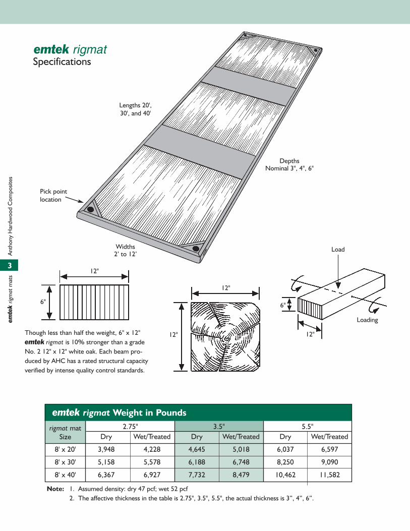
Pick point location
Depths Nominal 3", 4", 6"
Widths 2’ to 12’
Lengths 20',30', and 40'
Specificationsemtek rigmat
2.75" 3.5" 5.5"S 3 1/2" Dry Wet/Treated Dry Wet/Treated Dry Wet/Treated
8' x 20' 3,948 4,228 4,645 5,018 6,037 6,597
8' x 30' 5,158 5,578 6,188 6,748 8,250 9,090
8' x 40' 6,367 6,927 7,732 8,479 10,462 11,582
Note: 1. Assumed density: dry 47 pcf; wet 52 pcf2. The affective thickness in the table is 2.75", 3.5", 5.5", the actual thickness is 3”, 4”, 6”.
Load
Loading
12"
6"
12"
12"
12"
6"
emtek rigmat Weight in Pounds
rigmat matSize
Though less than half the weight, 6" x 12"emtek rigmat is 10% stronger than a gradeNo. 2 12" x 12" white oak. Each beam pro-duced by AHC has a rated structural capacityverified by intense quality control standards.
3
emte
k rig
mat
mat
s
Ant
hony
Har
dwoo
d C
ompo
sites

P1 P1
3.0' 3.0'
6.0'
L
Load Case 1
Span
CL
P3
L
Load Case 3
Span
CL
P2 P2
4.5' 4.5'
9.0'
L
Load Case 2
Span
CL
P4 P4
6.0'
L
Load Case 4
P5 P5
9.0'
L
Load Case 5
P6
L
Load Case 6
Load DiagramsUniform Bearing On Soil
Anthony Hardwood Composites
4
emtek rigm
atm
ats Anthony H
ardwood C
omposites
3.5' for 20' L.5' for 30' & 40' L.
3.5' for 20' L.5' for 30' & 40' L.
3.5' for 20' L.5' for 30' & 40' L.

Table ILoad Criteria (centered loading)
Load Per Linear Foot Of Width, K = Kip = 1,000 Lbs
Length Thickness Load Case 1 Load Case 2 Load Case 3
Feet Inches
5
emte
k rig
mat
mat
s
Ant
hony
Har
dwoo
d C
ompo
sites
40
30
20
40
30
20
40
30
20
P Load Defl. Bearing P Load Defl. Bearing P Load Defl. BearingKips Inches PSI Kips Inches PSI Kips Inches PSI
2.75 3.4 3.9 3.9 4.6 4.0 4.0 4.1 3.2 3.13.5 3.8 4.0 4.0 4.7 4.0 4.0 5.7 3.7 3.85.5 4.6 4.0 4.0 5.2 4.0 4.0 8.2 4.0 4.0
2.75 1.8 2.0 2.0 2.3 2.0 2.0 2.6 2.0 2.03.5 1.9 2.0 2.0 2.4 2.0 2.0 3.1 2.0 2.05.5 2.3 2.0 2.0 26 2.0 2.0 4.2 2.0 2.0
2.75 3.4 4.0 4.0 4.5 4.0 4.0 4.1 3.3 3.33.5 3.7 4.0 4.0 4.6 4.0 4.0 5.5 3.7 3.75.5 4.6 4.0 4.0 5.2 4.0 4.0 8.2 4.0 4.0
2.75 1.7 2.0 2.0 2.3 2.0 2.0 2.5 2.0 2.03.5 1.9 2.0 2.0 2.4 2.0 2.0 3.0 2.0 2.05.5 2.3 2.0 2.0 2.6 2.0 2.0 4.1 2.0 2.0
2.75 3.4 4.0 4.2 4.7 4.0 4.2 4.0 3.1 3.53.5 3.6 4.0 4.2 4.7 4.0 4.2 5.3 3.7 3.55.5 4.5 4.0 4.2 5.2 4.0 4.2 8.1 4.0 4.2
2.75 1.7 2.0 2.1 2.3 2.0 2.1 2.6 2.0 2.13.5 1.8 2.0 2.1 2.3 2.0 2.1 2.9 2.0 2.15.5 2.2 2.0 2.1 2.6 2.0 2.1 4.0 2.0 2.1
2.75 7 2.9 8.6 8.6 2.8 8.4 5.7 1.9 5.63.5 9.2 3.7 11 11.6 3.5 10.3 7.6 2.2 6.35.5 11.8 4.0 12 14.5 4.0 11.9 13 2.7 11.4
2.75 4.9 2.0 6.0 6.2 2.0 6.0 5.7 1.9 5.63.5 5.1 2.0 6.0 6.7 2.0 6.0 7.2 2.0 6.05.5 5.9 2.0 6.0 7.3 2.0 6.0 9.8 2.0 6.0
2.75 6.9 2.9 8.7 8.4 2.8 8.3 5.5 1.9 5.53.5 9.0 3.7 10.9 11.4 3.5 10.3 7.4 2.2 6.45.5 11.6 4.0 11.9 14.4 4.0 12.0 12.7 2.7 8.0
2.75 4.8 2.0 6.0 6.1 2.0 6.0 5.5 1.9 5.53.5 5.0 2.0 6.0 6.7 2.0 6.0 7.0 2.0 6.05.5 5.8 2.0 6.0 7.2 2.0 6.0 9.6 2.0 6.0
2.75 6.8 2.8 8.3 6.2 2.0 6.3 5.3 1.8 5.63.5 8.7 3.5 10.4 9.0 2.5 7.6 7.4 2.1 6.35.5 11.6 4.0 11.8 14.5 4.0 11.8 12.3 2.6 7.6
2.75 4.8 2.0 6.3 15.1 2.0 6.3 15.3 2.0 5.63.5 4.9 2.0 6.3 8.9 2.0 6.3 7.4 2.0 6.35.5 5.8 2.0 6.3 15.5 2.0 6.3 18.8 2.0 6.3
2.75 8 2.3 10.1 9.7 2.1 10.3 6.5 1.5 7.23.5 10.7 2.7 13.1 13.2 2.5 12.5 8.7 1.7 8.15.5 16.7 3.7 18.3 22.6 3.9 19.0 14.7 2.1 10.2
2.75 7.0 2.0 8.9 9.4 2.0 10.0 6.5 1.5 7.23.5 8.2 2.0 10.0 10.6 2.0 10.0 8.7 1.7 8.15.5 9.2 2.0 10.0 11.9 2.0 10.0 14.5 2.0 10.0
2.75 7.5 2.0 9.7 6.8 1.5 7.5 6.3 1.5 7.23.5 10.4 2.6 13.0 12.9 2.5 12.4 8.4 1.7 8.25.5 16.4 3.7 18.1 15.9 3.8 18.9 18.2 2.1 10.3
2.75 7.8 2.0 10.0 8.2 2.0 10.0 6.3 1.5 7.23.5 8.0 2.0 10.0 8.9 2.0 10.0 7.4 1.7 8.25.5 9.1 2.0 10.0 11.8 2.0 10.0 14.2 2.0 10.
2.75 7.7 2.0 11.8 6.7 1.4 6.9 6.0 1.4 6.93.5 10.4 2.6 13.2 9.8 1.9 8.3 8.2 1.6 6.35.5 15.9 3.5 17.4 19.0 3.2 16.0 14.2 2.0 9.7
2.75 7.7 2.0 9.7 6.7 2.0 6.9 6.0 2.0 6.93.5 8.0 2.0 9.7 9.8 2.0 9.7 8.2 2.0 8.35.5 9.0 2.0 9.7 11.8 2.0 9.7 14.2 2.0 9.7
Notes for Load Tables and Determining Loads: Reference page 7.
2.0Defl.Limit
2.0Defl.Limit
2.0Defl.Limit
2.0Defl.Limit
2.0Defl.Limit
2.0Defl.Limit
2.0Defl.Limit
2.0Defl.Limit
2.0Defl.Limit
Uniform Bearing On Soil Type "1"
Uniform Bearing On Soil Type "3"
Uniform Bearing On Soil Type "5"

6
emtek rigm
atm
ats Anthony H
ardwood C
omposites
Notes for Load Tables and Determining Loads: Reference page 7.
Table IILoad Criteria (offset loading)
Load Per Linear Foot Of Width, K = Kip = 1,000 Lbs
Length Thickness Load Case 4 Load Case 5 Load Case 6
Feet Inches
40
30
20
40
30
20
40
30
20
P Load Defl. Bearing P Load Defl. Bearing P Load Defl. BearingKips Inches PSI Kips Inches PSI Kips Inches PSI
2.75 3.4 3.9 3.9 4.5 4.0 4.0 4.7 4.0 4.03.5 3.7 4.0 4.0 4.7 4.0 4.0 4.9 4.0 4.05.5 3.9 4.0 4.0 5.1 4.0 4.0 4.4 4.0 3.8
2.75 1.7 2.0 2.0 2.3 2.0 2.0 2.4 2.0 2.03.5 1.9 2.0 2.0 2.4 2.0 2.0 2.5 2.0 2.05.5 2.0 2.0 2.0 2.6 2.0 2.0 2.2 2.0 1.9
2.75 3.4 4.0 4.0 4.4 4.0 4.0 4.7 4.0 4.03.5 3.7 4.0 4.0 4.6 4.0 4.0 4.9 4.0 4.05.5 3.8 4.0 4.0 4.6 4.0 4.0 4.3 4.0 3.8
2.75 1.7 2.0 2.0 2.2 2.0 2.0 2.4 2.0 2.03.5 1.9 2.0 2.0 2.3 2.0 2.0 2.5 2.0 2.05.5 1.9 2.0 2.0 2.3 2.0 2.0 2.2 2.0 1.9
2.75 3.2 4.0 4.2 3.8 4.0 4.2 2.7 4.0 3.53.5 3.4 4.0 4.2 4.1 4.0 4.2 3.4 4.0 4.25.5 3.1 4.0 4.2 3.8 4.0 4.2 3.1 4.0 4.2
2.75 1.6 2.0 2.1 1.9 2.0 2.1 15.3 2.0 2.13.5 1.7 2.0 2.1 2.0 2.0 2.1 7.4 2.0 2.15.5 1.5 2.0 2.1 1.9 2.0 2.1 18.8 2.0 2.1
2.75 6.7 2.8 8.3 6.2 2.1 6.2 5.6 1.9 5.73.5 9.1 3.6 10.8 8.8 2.7 7.9 8.2 2.4 7.25.5 11.6 4.0 11.9 14.6 4.0 11.9 14.2 4.0 11.4
2.75 4.8 2.0 6.0 6.0 2.0 6.0 5.6 1.9 5.73.5 5.1 2.0 6.0 6.7 2.0 6.0 6.8 2.0 6.05.5 5.8 2.0 6.0 7.4 2.0 6.0 7.2 2.0 5.9
2.75 6.7 2.8 8.4 6.3 2.1 910 15.3 1.9 5.73.5 9.1 3.7 10.9 6.4 2.8 8.3 8.1 2.4 7.25.5 11.4 4.0 11.9 14 4.0 11.9 14 4.0 11.8
2.75 4.8 2.0 6.0 6.0 2.0 6.0 5.6 1.9 5.73.5 5.0 2.0 6.0 4.7 2.0 6.0 6.8 2.0 6.05.5 5.7 2.0 6.0 7.0 2.0 6.0 7.0 2.0 5.9
2.75 6.8 2.9 9.0 6.1 2.2 6.9 6.5 2.7 8.33.5 9.9 4.0 11.8 9.0 2.9 9.0 9.7 3.4 10.45.5 10.3 4.0 11.8 12.4 4.0 11.8 10.1 4.0 11.8
2.75 4.7 2.0 6.3 5.5 2.0 6.3 4.8 2.0 6.33.5 4.9 2.0 6.3 6.1 2.0 6.3 5.7 2.0 6.35.5 5.1 2.0 6.3 6.2 2.0 6.3 5.0 2.0 6.3
2.75 7.5 2.0 9.7 6.8 1.5 7.5 6.3 1.5 7.23.5 10.3 2.6 12.6 9.7 1.9 9.3 8.8 1.8 8.55.5 18.4 4.0 20.0 18.9 3.2 15.9 18.6 3.0 14.9
2.75 7.5 2.0 9.7 6.8 1.5 7.5 6.3 1.5 7.23.5 8.2 2.0 10.1 9.7 1.9 9.3 8.8 1.8 8.55.5 9.2 2.0 10.0 11.9 2.0 10.1 12.6 2.0 10.0
2.75 7.5 2.0 9.7 6.8 1.5 7.5 15.3 1.5 7.23.5 10.3 2.6 12.8 10.0 2.0 9.7 8.8 1.8 8.55.5 17.6 3.9 19.4 18.8 3.3 16.3 18.3 3.0 14.9
2.75 7.5 2.0 9.7 6.8 1.5 7.5 6.3 1.5 7.23.5 8.1 2.0 10.1 10.0 2.0 9.7 8.8 1.8 8.55.5 9.1 2.0 10.1 11.6 2.0 10.0 12.3 2.0 10.0
2.75 7.4 2.0 9.7 6.7 1.6 7.6 6.9 1.8 9.03.5 11.4 2.8 13.9 9.9 2.0 9.7 10.0 2.1 10.45.5 17.1 4.0 20.1 18.9 3.6 18.1 17.1 4.0 20.1
2.75 7.4 2.0 9.7 6.7 2.0 7.6 6.9 2.0 9.03.5 8.1 4.0 9.7 9.9 4.0 9.7 9.5 4.0 9.75.5 8.5 2.0 9.7 10.5 2.0 9.7 8.5 2.0 9.7
2.0Defl.Limit
2.0Defl.Limit
2.0Defl.Limit
2.0Defl.Limit
2.0Defl.Limit
2.0Defl.Limit
2.0Defl.Limit
2.0Defl.Limit
2.0Defl.Limit
Uniform Bearing On Soil Type "1"
Uniform Bearing On Soil Type "3"
Uniform Bearing On Soil Type "5"

NOTES FOR LOAD TABLES
1. In each mat length section, the first two rows indicate deflections up to 4” (in bold) if acceptable. The last two rows reflects deflection of no more than 2”.
2. Loads listed are based on a uniform soil bearing analysis using a simplified elastic soil procedure where the soil is assumed to act as a line of springs spaced one footapart along the length with resistance directly proportional to settlement. (Similar to the subgrade modulus procedures for slab and paving design, except, withhigher deflections allowed).
Type "1" (SGM-1) soil has a spring constant of 144 pounds per square foot, per inch settlement. Type "3" (SGM-3) soil has a spring constant of 432 pounds persquare foot, per inch of settlement. Type "5" (SGM-5) soil has a spring constant of 720 pounds per square foot, per inch of settlement.
3. Loads listed in Table 7 are based on normal simple span beam design methods. Adequate bearing must be provided at the ends to support the loads.
4. Load duration - Loads listed in all tables are based on a stress increase of 1/3 (33 1/3%) for short duration loading. Where stresses govern the load, applied longterm loads should be reduced accordingly and as much as 1/3 less for long term loading or frequent cycles of loading.
5. Load distribution - Load Tables are based on a unit width one foot wide perpendicular to the length. Loads can be assumed distributed over more than one footdepending on the type of load and loading conditions.
6. Edge loading - Load cases 4, 5, & 6 as shown in the load diagrams, are based on off-center loading. Under edge loading conditions the unloaded end of the memberwill deflect upward and should be considered when using edge loading.
Determining Loads
Load tables are subject to interpretation and use for a variety of conditions. For load cases where uniform bearing is used: first the soil strength should be estimatedand then using the tables for the various soil types and the load case that compares closest to the load conditions, the thickness and length can be selected; alterna-tively, for an existing thickness and length the estimated load resistance can be determined from the Tables.
Soil Type "1" (SGM-1) is soft soil and in theory a 200 lb person standing on a one foot by one foot (1ft2) block would settle into the surface 1 3/8".
For Soil Type "3" (SGM-3) the same 200 lbs on a one foot square would settle 7/16".
For Soil Type "5" (SGM-5) the same 200 lbs on a one foot square would settle 1/4"±.
For estimating soil strength using simplified bearing tests as described above, results should be based on incremental loads. Divide the resulting pressure in poundsper square inch by the settlement, and the results averaged to determine an estimated SGM.
For areas where geotechnical reports are required the geotechnical engineering should be requested to provide an estimated bearing capacity of the bearing strata,and if practical, in the form of subgrade modulus for settlement estimated in the range of one to two inches.
emte
k rig
mat
mat
s
Ant
hony
Har
dwoo
d C
ompo
sites
A = t(b) I = bt3 S = bt2 MA = FbS VA = FV A ~ FV Ib
12 6 1.5 Q
K = KIP = 1000 lbs
MA = Allowable Moment W/1.33 Load Duration Factor
VA = Allowable Shear W/1.33
Fb = 4123 psi
Fv = 379 psi
E = 1.6 (10)6 psi
W/ 1.33 Load Duration Factor
A I S MA VAIn2 In4 In3 K-Ft K
2.75" 33 20.797 15.13 5.197 8.3393.5" 42 42.875 24.50 8.418 10.6135.5" 66 166.375 60.50 20.787 16.676
emtek Design Properties
Thickness
Unit Section Properties
( )Note: The affective thickness in the table is 2.75", 3.5", 5.5", the actual thickness is 3”, 4”, 6”.
7

NOTES & CALCULATIONSemtekH E A V Y E Q U I P M E N T M A T
TM

Anthony Hardwood Composites
Mailing:PO Box 490
Sheridan, AR 72150-0490
Shipping:606 E. Center StreetSheridan, AR 72150
Phone 1-870-942-4000Fax 1-870-942-4040
www.anthonycomposites.com