Embed Size (px)
Citation preview
Rigid and Intermediate Metal Conduit Fittings
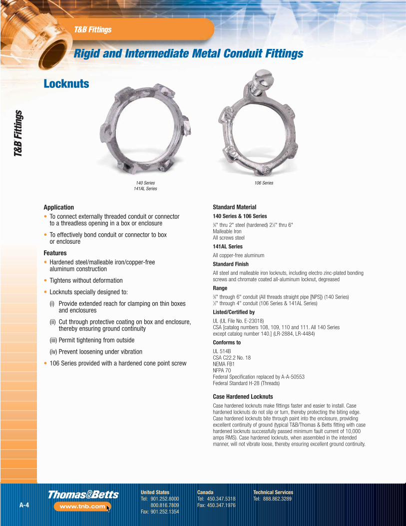
Locknuts
Application• To connect externally threaded conduit or connector
to a threadless opening in a box or enclosure
• To effectively bond conduit or connector to box or enclosure
Features• Hardened steel/malleable iron/copper-free
aluminum construction
• Tightens without deformation
• Locknuts specially designed to:
(i) Provide extended reach for clamping on thin boxes and enclosures
(ii) Cut through protective coating on box and enclosure,thereby ensuring ground continuity
(iii) Permit tightening from outside
(iv) Prevent loosening under vibration
• 106 Series provided with a hardened cone point screw
Standard Material140 Series & 106 Series3⁄8" thru 2" steel (hardened) 21⁄2" thru 6" Malleable IronAll screws steel
141AL Series
All copper-free aluminum
Standard Finish
All steel and malleable iron locknuts, including electro zinc-plated bondingscrews and chromate coated all-aluminum locknut, degreased
Range3⁄8" through 6" conduit (All threads straight pipe [NPS]) (140 Series) 1⁄2" through 4" conduit (106 Series & 141AL Series)
Listed/Certified by
UL (UL File No. E-23018)CSA [catalog numbers 108, 109, 110 and 111. All 140 Series except catalog number 140.] (LR-2884, LR-4484)
Conforms to
UL 514BCSA C22.2 No. 18NEMA FB1NFPA 70Federal Specification replaced by A-A-50553Federal Standard H-28 (Threads)
Case Hardened LocknutsCase hardened locknuts make fittings faster and easier to install. Casehardened locknuts do not slip or turn, thereby protecting the biting edge.Case hardened locknuts bite through paint into the enclosure, providingexcellent continuity of ground (typical T&B/Thomas & Betts fitting with casehardened locknuts successfully passed minimum fault current of 10,000amps RMS). Case hardened locknuts, when assembled in the intendedmanner, will not vibrate loose, thereby ensuring excellent ground continuity.
140 Series141AL Series
106 Series
A-4
United StatesTel: 901.252.8000
800.816.7809Fax: 901.252.1354
CanadaTel: 450.347.5318Fax: 450.347.1976
Technical ServicesTel: 888.862.3289
www.tnb.com
Rigid and Intermediate Metal Conduit Fittings
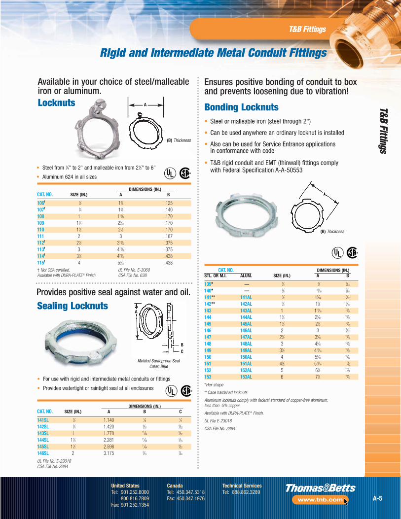
Available in your choice of steel/malleableiron or aluminum.
Ensures positive bonding of conduit to boxand prevents loosening due to vibration!
Bonding Locknuts• Steel or malleable iron (steel through 2")
• Can be used anywhere an ordinary locknut is installed
• Also can be used for Service Entrance applications in conformance with code
• T&B rigid conduit and EMT (thinwall) fittings comply with Federal Specification A-A-50553
Molded Santoprene SealColor: Blue
BC
A
(B) Thickness
®
®
DIMENSIONS (IN.)CAT. NO. SIZE (IN.) A B
106† 1⁄2 13⁄8 .125107† 3⁄4 15⁄8 .140108 1 115⁄16 .170109 11⁄4 25⁄32 .170110 11⁄2 21⁄2 .170111 2 3 .187112† 21⁄2 313⁄32 .375113† 3 413⁄16 .375114† 31⁄2 429⁄32 .438115† 4 57⁄32 .438
®
®
DIMENSIONS (IN.)CAT. NO. SIZE (IN.) A B C
141SL 1⁄2 1.140 1⁄8 1⁄4142SL 3⁄4 1.420 5⁄32
9⁄32
143SL 1 1.770 11⁄649⁄32
144SL 11⁄4 2.281 11⁄645⁄16
145SL 11⁄2 2.598 11⁄649⁄32
146SL 2 3.175 3⁄167⁄64
UL File No. E-23018CSA File No. 2884
®
®
CAT. NO. DIMENSIONS (IN.)STL. OR M.I. ALUM. SIZE (IN.) A B
139* — 1⁄4 3⁄4 9⁄64
140* — 3⁄8 15⁄169⁄64
141** 141AL 1⁄2 17⁄645⁄32
142** 142AL 3⁄4 13⁄8 3⁄16
143 143AL 1 111⁄1613⁄64
144 144AL 11⁄4 25⁄3213⁄64
145 145AL 11⁄2 21⁄2 13⁄64
146 146AL 2 3 7⁄32
147 147AL 21⁄2 39⁄1613⁄32
148 148AL 3 43⁄1613⁄32
149 149AL 31⁄2 413⁄1615⁄32
150 150AL 4 55⁄1615⁄32
151 151AL 41⁄2 515⁄1617⁄32
152 152AL 5 61⁄2 17⁄32
153 153AL 6 73⁄4 19⁄32
*Hex shape
**Case hardened locknuts
Aluminum locknuts comply with federal standard of copper-free aluminum; less than .5% copper.
Available with DURA-PLATE ® Finish.
UL File E-23018
CSA File No. 2884
† Not CSA certified.Available with DURA-PLATE® Finish.
UL File No. E-3060CSA File No. 638
• Steel from 1⁄4" to 2" and malleable iron from 21⁄2" to 6"
• Aluminum 624 in all sizes
Locknuts
Provides positive seal against water and oil.
(B) Thickness
A
• For use with rigid and intermediate metal conduits or fittings
• Provides watertight or raintight seal at all enclosures
Sealing Locknuts
A-5
United StatesTel: 901.252.8000
800.816.7809Fax: 901.252.1354
CanadaTel: 450.347.5318Fax: 450.347.1976
Technical ServicesTel: 888.862.3289
www.tnb.com
Rigid and Intermediate Metal Conduit Fittings
Bonding & Grounding Wedges
Sealing Rings withStainless Steel Retainer
DIMENSIONS (IN.)CAT. NO. CONDUIT SIZE A B ± 1/64
5302 1⁄2" 111⁄643⁄4
5303 3⁄4" 11⁄2 15⁄16
5304 1" 13⁄4 111⁄64
5305 11⁄4" 29⁄64 11⁄25306 11⁄2" 2& 13⁄45307 2" 259⁄64 215⁄64
5308 21⁄2" 37⁄16 243⁄64
5309 3" 45⁄64 319⁄64
5311 4" 59⁄32 419⁄64
NEMA 3R, 4, 6 & 13 UL File No. E-13938 CSA File No. 2884
AB
Application• To effectively bond terminating fitting or conduit
to a box or enclosure
Features• Sizes 3⁄4" thru 6" equipped with an additional bonding
screw to install bonding jumper where required
• Can be added to an existing installation withoutdisconnecting conductors
Grounding WedgesCAT. NO. SIZE
3650 1⁄2"3651 3⁄4"3652 1"3653 11⁄4"3654 11⁄2"3655 2"3656 21⁄2"3657 3"3658 31⁄2"3659 4"3661 5"3662 6"
UL File No. E-3060
• Provides grounding without a jumper except in concentric knockouts
• When jumper is required, it fits under set screw in grounding wedge
• Update existing installations to meet code requirements forbonding (NEC Sect. 250-72e) without disconnecting wiring
• For use on new wiring, just loosen bushing, position wedge and tighten bushing and bonding screw
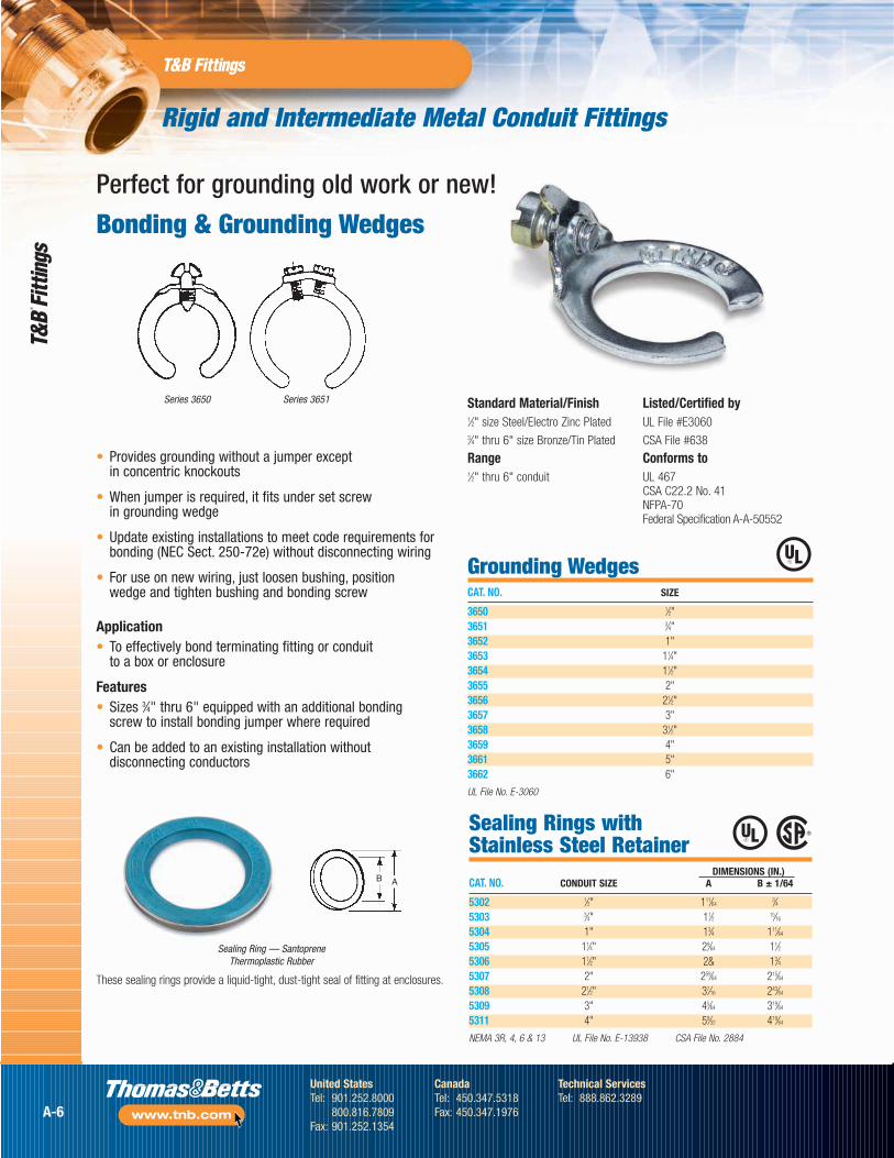
Series 3651Series 3650
Perfect for grounding old work or new!
Sealing Ring — Santoprene Thermoplastic Rubber
These sealing rings provide a liquid-tight, dust-tight seal of fitting at enclosures.
Standard Material/Finish1⁄2" size Steel/Electro Zinc Plated3⁄4" thru 6" size Bronze/Tin Plated
Range1⁄2" thru 6" conduit
Listed/Certified byUL File #E3060
CSA File #638
Conforms toUL 467CSA C22.2 No. 41NFPA-70Federal Specification A-A-50552
A-6
United StatesTel: 901.252.8000
800.816.7809Fax: 901.252.1354
CanadaTel: 450.347.5318Fax: 450.347.1976
Technical ServicesTel: 888.862.3289
www.tnb.com
Rigid and Intermediate Metal Conduit Fittings
Blackjack® — Grounding Bushing
The Blackjack® Grounding Bushing never has to be threaded onto a conduit. It is simply placedin position on either a threaded or non-threadedrigid or IMC conduit, with the grounding lug inperfect position to accept the grounding wire —even in tight installations.
It’s as simple as one, two, three!
Compare the installation with conventionalbushings that must be threaded onto theconduit. In tight areas, you may have to remove
the grounding lug, keep up with the loose partsand then reattach the lug. Then you still have to twist and turn the bushing to get the lug in position to accept the grounding wire.
The Blackjack bushing does away with theseneedless delays for good, making it the idealgrounding bushing — and the only logicalchoice for small spaces, corners and multipleconduit runs. And, because the grounding lug is an integral part of the bushing, it's designednot to fall off or get lost.
Lug Screw:
14-4: Slotted
14-2/0: Slotted
6-4/0: Internal Hex Drive
Standard Material/FinishBody: Malleable Iron or Aluminum
Mounting Screw: (1⁄2"–2") Stainless Steel,(21⁄2"–6") Brass
Lug Screw: Stainless Steel
Finish: Zinc Plated or Mechanical Galvanized
RangeConduit: 1⁄2" thru 6" threaded or threadlessrigid/IMC
Wire Range: #14 AWG to 4/0 AWG CU/AL
Listed/Certified byUL File #E3060
CSA File #LR2884
Conforms toUL 514B & U.L. 467
CSA C22.2 No. 18 & CSA C22.2 No. 41
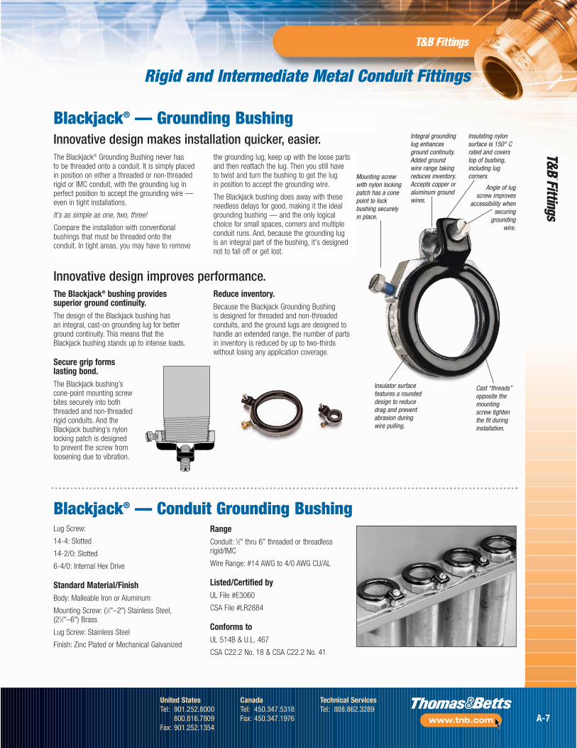
Mounting screwwith nylon lockingpatch has a conepoint to lockbushing securely in place.
Insulator surfacefeatures a roundeddesign to reducedrag and preventabrasion duringwire pulling.
Cast “threads”opposite themountingscrew tightenthe fit duringinstallation.
Angle of lugscrew improves
accessibility whensecuring
groundingwire.
Integral groundinglug enhancesground continuity.Added groundwire range takingreduces inventory.Accepts copper oraluminum groundwires.
Insulating nylonsurface is 150° Crated and coverstop of bushing,including lugcorners.
The Blackjack® bushing providessuperior ground continuity.The design of the Blackjack bushing has an integral, cast-on grounding lug for betterground continuity. This means that the Blackjack bushing stands up to intense loads.
Secure grip forms lasting bond.The Blackjack bushing’scone-point mounting screwbites securely into boththreaded and non-threaded rigid conduits. And theBlackjack bushing’s nylonlocking patch is designed to prevent the screw fromloosening due to vibration.
Reduce inventory.Because the Blackjack Grounding Bushing is designed for threaded and non-threadedconduits, and the ground lugs are designed tohandle an extended range, the number of partsin inventory is reduced by up to two-thirdswithout losing any application coverage.
Blackjack® — Conduit Grounding Bushing
Innovative design makes installation quicker, easier.
Innovative design improves performance.
A-7
United StatesTel: 901.252.8000
800.816.7809Fax: 901.252.1354
CanadaTel: 450.347.5318Fax: 450.347.1976
Technical ServicesTel: 888.862.3289
www.tnb.com
Rigid and Intermediate Metal Conduit Fittings
Blackjack® Grounding Bushing Technical Information
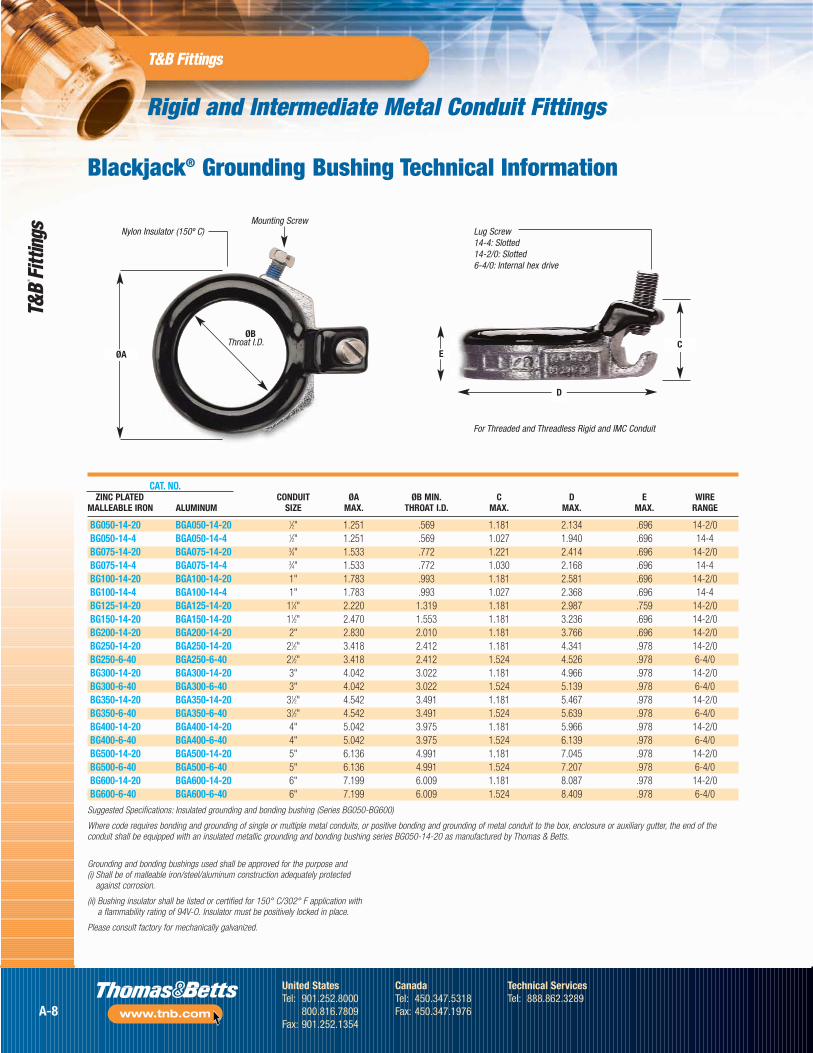
Lug Screw14-4: Slotted14-2/0: Slotted6-4/0: Internal hex drive
For Threaded and Threadless Rigid and IMC Conduit
Nylon Insulator (150º C)Mounting Screw
ØBThroat I.D.
CAT. NO.ZINC PLATED CONDUIT ØA ØB MIN. C D E WIRE
MALLEABLE IRON ALUMINUM SIZE MAX. THROAT I.D. MAX. MAX. MAX. RANGE
BG050-14-20 BGA050-14-20 1⁄2" 1.251 .569 1.181 2.134 .696 14-2/0BG050-14-4 BGA050-14-4 1⁄2" 1.251 .569 1.027 1.940 .696 14-4BG075-14-20 BGA075-14-20 3⁄4" 1.533 .772 1.221 2.414 .696 14-2/0BG075-14-4 BGA075-14-4 3⁄4" 1.533 .772 1.030 2.168 .696 14-4BG100-14-20 BGA100-14-20 1" 1.783 .993 1.181 2.581 .696 14-2/0BG100-14-4 BGA100-14-4 1" 1.783 .993 1.027 2.368 .696 14-4BG125-14-20 BGA125-14-20 11⁄4" 2.220 1.319 1.181 2.987 .759 14-2/0BG150-14-20 BGA150-14-20 11⁄2" 2.470 1.553 1.181 3.236 .696 14-2/0BG200-14-20 BGA200-14-20 2" 2.830 2.010 1.181 3.766 .696 14-2/0BG250-14-20 BGA250-14-20 21⁄2" 3.418 2.412 1.181 4.341 .978 14-2/0BG250-6-40 BGA250-6-40 21⁄2" 3.418 2.412 1.524 4.526 .978 6-4/0BG300-14-20 BGA300-14-20 3" 4.042 3.022 1.181 4.966 .978 14-2/0BG300-6-40 BGA300-6-40 3" 4.042 3.022 1.524 5.139 .978 6-4/0BG350-14-20 BGA350-14-20 31⁄2" 4.542 3.491 1.181 5.467 .978 14-2/0BG350-6-40 BGA350-6-40 31⁄2" 4.542 3.491 1.524 5.639 .978 6-4/0BG400-14-20 BGA400-14-20 4" 5.042 3.975 1.181 5.966 .978 14-2/0BG400-6-40 BGA400-6-40 4" 5.042 3.975 1.524 6.139 .978 6-4/0BG500-14-20 BGA500-14-20 5" 6.136 4.991 1.181 7.045 .978 14-2/0BG500-6-40 BGA500-6-40 5" 6.136 4.991 1.524 7.207 .978 6-4/0BG600-14-20 BGA600-14-20 6" 7.199 6.009 1.181 8.087 .978 14-2/0BG600-6-40 BGA600-6-40 6" 7.199 6.009 1.524 8.409 .978 6-4/0
Suggested Specifications: Insulated grounding and bonding bushing (Series BG050-BG600)
Where code requires bonding and grounding of single or multiple metal conduits, or positive bonding and grounding of metal conduit to the box, enclosure or auxiliary gutter, the end of theconduit shall be equipped with an insulated metallic grounding and bonding bushing series BG050-14-20 as manufactured by Thomas & Betts.
Grounding and bonding bushings used shall be approved for the purpose and (i) Shall be of malleable iron/steel/aluminum construction adequately protected
against corrosion.
(ii) Bushing insulator shall be listed or certified for 150° C/302° F application with a flammability rating of 94V-O. Insulator must be positively locked in place.
Please consult factory for mechanically galvanized.
C
D
EØA
A-8
United StatesTel: 901.252.8000
800.816.7809Fax: 901.252.1354
CanadaTel: 450.347.5318Fax: 450.347.1976
Technical ServicesTel: 888.862.3289
www.tnb.com
Rigid and Intermediate Metal Conduit Fittings
WIRERANGE
CONDUIT BUSHING THROAT LUG SWING BUSHING AWGCAT. NO. SIZE DIA. DIA. LENGTH RADIUS HEIGHT CU/AL
3870-TB 1⁄2" 1.125 .560 1.310 1.212 .657 14-43861 1⁄2" 1.125 .560 1.675 1.402 .657 8-2/03871-TB 3⁄4" 1.420 .742 1.310 1.360 .660 14-43862 3⁄4" 1.420 .742 1.675 1.550 .660 8-2/03872 1" 1.770 .944 1.310 1.535 .735 14-43882 1" 1.770 .944 1.675 1.725 .735 8-2/03873 11⁄4" 2.190 1.242 1.310 1.745 .735 14-43883 11⁄4" 2.190 1.242 1.675 1.935 .735 8-2/03874 11⁄2" 2.468 1.449 1.310 1.884 .770 14-43884 11⁄2" 2.468 1.449 1.675 2.074 .770 8-2/03875 2" 3.031 1.860 1.310 2.165 .770 14-43889 2" 3.031 1.860 1.675 2.355 .770 8-2/03876 21⁄2" 3.516 2.222 1.310 2.408 .940 14-43886 21⁄2" 3.516 2.222 1.675 2.598 .940 8-2/03993 21⁄2" 3.516 2.222 2.230 2.928 .940 6-4/03877 3" 4.234 2.761 1.310 2.767 .975 14-43887 3" 4.234 2.761 1.675 2.957 .975 8-2/03994 3" 4.234 2.761 2.230 3.287 .975 6-4/03878 31⁄2" 4.781 3.193 1.310 3.040 .975 14-43863 31⁄2" 4.781 3.193 1.675 3.230 .975 8-2/03995 31⁄2" 4.781 3.193 2.230 3.560 .975 6-4/03879 4" 5.328 3.623 1.310 3.314 .980 14-43864 4" 5.328 3.623 1.675 3.504 .980 8-2/03996 4" 5.328 3.623 2.230 3.834 .980 6-4/03880 5" 6.328 4.542 1.310 3.814 .985 14-43865 5" 6.328 4.542 1.675 4.000 .985 8-2/03998 5" 6.328 4.542 2.230 4.334 .985 6-4/03881 6" 7.406 5.458 1.310 4.353 1.200 14-43866 6" 7.406 5.458 1.675 4.543 1.200 8-2/03999 6" 7.406 5.458 2.230 4.875 1.200 6-4/0
Temperature rating 150° C
Meets Coast Guard Regulation CG293
Available with DURA-PLATE ® Finish.
Application• For quick installation of bonding jumper
to multiple metal conduits (Rigid and IMC)
• Designed to bush conductors and prevent insulation damage
Features• Ease of installation, lay in lug design
• Cast malleable iron body designed to lock insulator in place within body, reducing common assembly problem resulting in dislodging of insulator
• Insulator rated for 150° C/302° F application
• Look for the unique T&B blue color, ensuring the highest quality fitting
Standard Material/FinishBody: Electro zinc plated
Lay-In Lug: Aluminum/tin plated
Insulator: Thermoplastic 150° C/302° FApplication with 94V-0 flammability
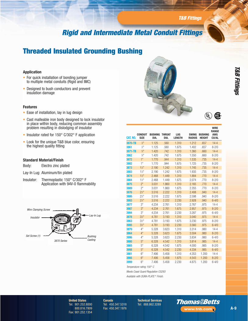
Wire Clamping Screw
Insulator
Set Screw (1)
3870 Series
Lay-In Lug
BushingCasting
®
®
Threaded Insulated Grounding Bushing
A-9
United StatesTel: 901.252.8000
800.816.7809Fax: 901.252.1354
CanadaTel: 450.347.5318Fax: 450.347.1976
Technical ServicesTel: 888.862.3289
www.tnb.com
Rigid and Intermediate Metal Conduit Fittings
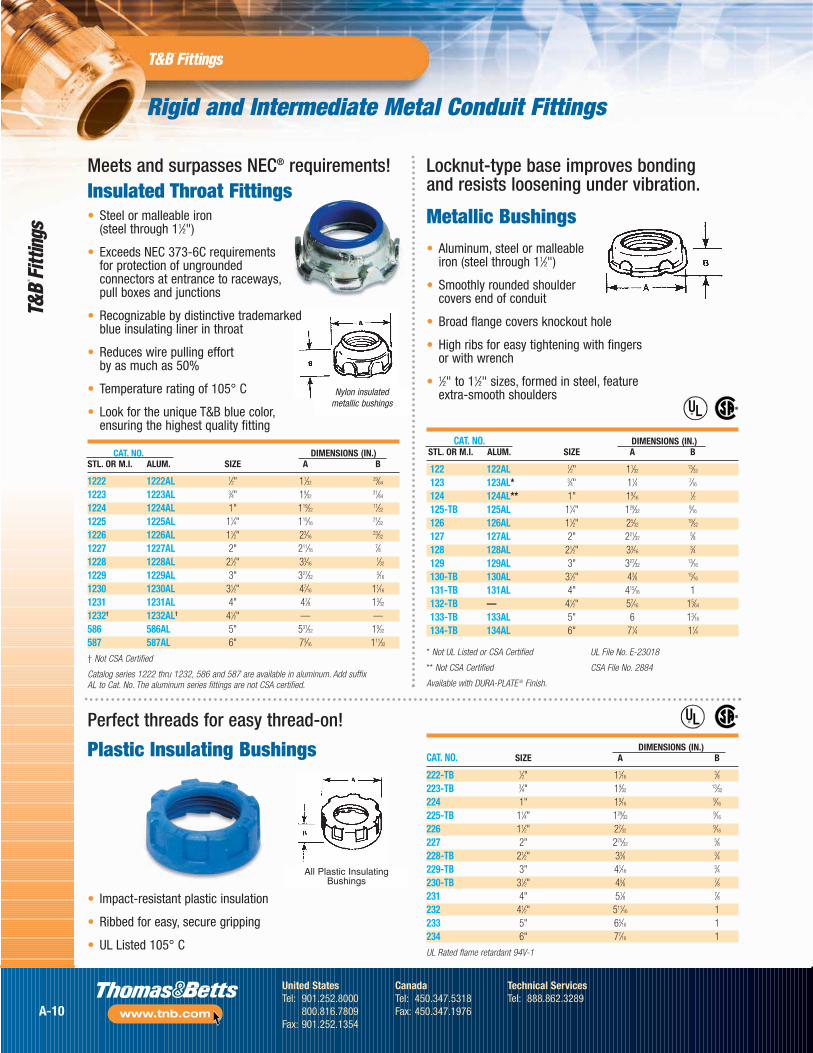
Meets and surpasses NEC® requirements!Insulated Throat Fittings
Locknut-type base improves bonding and resists loosening under vibration.
• Aluminum, steel or malleable iron (steel through 11⁄2")
• Smoothly rounded shoulder covers end of conduit
• Broad flange covers knockout hole
• High ribs for easy tightening with fingersor with wrench
• 1⁄2" to 11⁄2" sizes, formed in steel, feature extra-smooth shoulders
Metallic Bushings
Perfect threads for easy thread-on!
• Impact-resistant plastic insulation
• Ribbed for easy, secure gripping
• UL Listed 105° C
Plastic Insulating Bushings
All Plastic InsulatingBushings
CAT. NO. DIMENSIONS (IN.)STL. OR M.I. ALUM. SIZE A B
122 122AL 1⁄2" 11⁄3213⁄32
123 123AL* 3⁄4" 11⁄4 7⁄16
124 124AL** 1" 19⁄161⁄2
125-TB 125AL 11⁄4" 129⁄329⁄16
126 126AL 11⁄2" 25⁄3219⁄32
127 127AL 2" 221⁄325⁄8
128 128AL 21⁄2" 33⁄163⁄4
129 129AL 3" 327⁄3213⁄16
130-TB 130AL 31⁄2" 43⁄8 15⁄16
131-TB 131AL 4" 415⁄16 1132-TB — 41⁄2" 57⁄16 15⁄64
133-TB 133AL 5" 6 13⁄16
134-TB 134AL 6" 71⁄4 11⁄4
CAT. NO. DIMENSIONS (IN.)STL. OR M.I. ALUM. SIZE A B
1222 1222AL 1⁄2" 11⁄3229⁄64
1223 1223AL 3⁄4" 19⁄3231⁄64
1224 1224AL 1" 119⁄3211⁄32
1225 1225AL 11⁄4" 115⁄1621⁄32
1226 1226AL 11⁄2" 23⁄1623⁄32
1227 1227AL 2" 211⁄167⁄8
1228 1228AL 21⁄2" 33⁄161⁄32
1229 1229AL 3" 327⁄325⁄16
1230 1230AL 31⁄2" 47⁄16 11⁄16
1231 1231AL 4" 47⁄8 13⁄32
1232† 1232AL† 41⁄2" — —586 586AL 5" 531⁄32 19⁄32
587 587AL 6" 73⁄16 111⁄32
† Not CSA Certified
Catalog series 1222 thru 1232, 586 and 587 are available in aluminum. Add suffix AL to Cat. No. The aluminum series fittings are not CSA certified.
* Not UL Listed or CSA Certified
** Not CSA Certified
Available with DURA-PLATE ® Finish.
UL File No. E-23018
CSA File No. 2884
®
®
DIMENSIONS (IN.)CAT. NO. SIZE A B
222-TB 1⁄2" 11⁄163⁄8
223-TB 3⁄4" 19⁄3213⁄32
224 1" 19⁄169⁄16
225-TB 11⁄4" 129⁄329⁄16
226 11⁄2" 27⁄329⁄16
227 2" 225⁄325⁄8
228-TB 21⁄2" 33⁄8 3⁄4229-TB 3" 41⁄16
3⁄4230-TB 31⁄2" 45⁄8 7⁄8231 4" 51⁄8 7⁄8232 41⁄2" 511⁄16 1233 5" 65⁄16 1234 6" 77⁄16 1
UL Rated flame retardant 94V-1
®
®
Nylon insulatedmetallic bushings
• Steel or malleable iron (steel through 11⁄2")
• Exceeds NEC 373-6C requirements for protection of ungrounded connectors at entrance to raceways,pull boxes and junctions
• Recognizable by distinctive trademarkedblue insulating liner in throat
• Reduces wire pulling effort by as much as 50%
• Temperature rating of 105° C
• Look for the unique T&B blue color,ensuring the highest quality fitting
A-10
United StatesTel: 901.252.8000
800.816.7809Fax: 901.252.1354
CanadaTel: 450.347.5318Fax: 450.347.1976
Technical ServicesTel: 888.862.3289
www.tnb.com
Rigid and Intermediate Metal Conduit Fittings
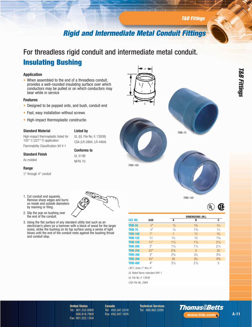
DIMENSIONS (IN.)CAT. NO. SIZE A B C
TRIB-50 1⁄2" 19⁄32 19⁄32 11⁄16
TRIB-75 3⁄4" 25⁄32 125⁄64 11⁄4TRIB-100 1" 1 11⁄2 19⁄16
TRIB-125 11⁄4 15⁄16 15⁄8 159⁄64
TRIB-150 11⁄2" 117⁄32 121⁄32 211⁄64
TRIB-200 2" 131⁄32 113⁄16 211⁄16
TRIB-250 21⁄2" 223⁄64 2 31⁄4TRIB-300 3" 259⁄64 27⁄32 329⁄32
TRIB-350 31⁄2" 33⁄8 25⁄16 429⁄64
TRIB-400 4" 327⁄32 213⁄32 5
I.M.C. sizes 1⁄2" thru 4"
UL Rated flame retardant 94V-1
UL File No. E-13938
CSA File No. 2884
Application• When assembled to the end of a threadless conduit,
provides a well-rounded insulating surface over whichconductors may be pulled or on which conductors maybear while in service
Features• Designed to be popped onto, and bush, conduit end
• Fast, easy installation without screws
• High-impact thermoplastic constructio
C
B
A
®
®
1. Cut conduit end squarely.Remove sharp edges and burrson inside and outside diametersby reaming or filing.
2. Slip the pop-on bushing overthe end of the conduit.
3. Using the flat surface of any standard utility tool such as anelectrician’s pliers (or a hammer with a block of wood for the largersizes), strike the bushing on its top surface using a series of lightblows until the end of the conduit rests against the bushing throat and conduit stop.
Standard MaterialHigh-impact thermoplastic listed for105° C (221° F) application
Flammability Classification 94 V-1
Standard FinishAs molded
Range1⁄2" through 4" conduit
Listed byUL (UL File No. E-13938)
CSA (LR-2884, LR-4484)
Conforms toUL 514B
NFPA 70
TRIB-150
TRIB-100
TRIB-75
For threadless rigid conduit and intermediate metal conduit.Insulating Bushing
A-11
United StatesTel: 901.252.8000
800.816.7809Fax: 901.252.1354
CanadaTel: 450.347.5318Fax: 450.347.1976
Technical ServicesTel: 888.862.3289
www.tnb.com
DIMENSION (IN.)CAT. NO. SIZE A B
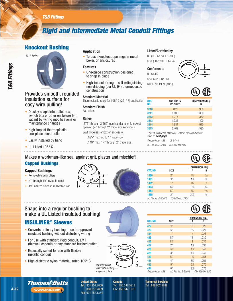
422 1⁄2" 5⁄8 .025423 3⁄4" 11⁄16 .025424 1" 7⁄8 .025425 11⁄4" 1 .030426 11⁄2" 1 .030427 2" 11⁄8 .030428 21⁄2" 11⁄4 .040429 3" 11⁄2 .040430 31⁄2" 125⁄32 .055431 4" 21⁄32 .055433 5" 21⁄2 .070434 6" 21⁄2 .070Oxygen index >28° UL File No. E-23018 CSA File No. 589
Rigid and Intermediate Metal Conduit Fittings
Application• To bush knockout openings in metal
boxes or enclosures
Features• One-piece construction designed
to snap in place
• High-impact strength, self extinguishing,non-dripping (per UL 94) thermoplasticconstruction
Standard MaterialThermoplastic rated for 105° C (221° F) application
Standard FinishAs molded
Range.875" through 2.469" nominal diameter knockoutopening (1⁄2" through 2" trade size knockouts)
Wall thickness of box or enclosure
.095" max. up to 1" trade size
.140" max. 11⁄4" through 2" trade size
Snaps into a regular bushing to make a UL Listed insulated bushing!
INSULINER® Sleeves• Converts ordinary bushing to code-approved
insulated bushing without disturbing wiring
• For use with standard rigid conduit, EMT (thinwall conduit) or any standard bushed outlet
• Especially suited for use with flexible metallic conduit
• High-dielectric nylon material, rated 105° C
Knockout Bushing
Provides smooth, roundedinsulation surface foreasy wire pulling!• Quickly snaps into outlet box,
switch box or other enclosure leftvacant by wiring modifications ormaintenance changes
• High-impact thermoplastic,one-piece construction
• Easily installed by hand
• UL Listed 105° C
Listed/Certified byUL (UL File No. E-3803)
CSA (LR-589,LR-4484)
Conforms toUL 514B
CSA C22.2 No. 18
NFPA 70-1999 (ANSI)
DIMENSION (IN.)CAT. NO. SIZE A B
1460 1⁄2" 11⁄3213⁄32
1461 3⁄4" 11⁄4 7⁄16
1462 1" 19⁄161⁄2
1463 11⁄4" 129⁄329⁄16
1464 11⁄2" 25⁄3219⁄32
1465 2" 221⁄325⁄8
UL File No. E-23018 CSA File No. 2884
Capped Bushings• Removable with pliers
• 1⁄2" through 11⁄4" sizes in steel
• 11⁄2" and 2" sizes in malleable iron
Makes a workman-like seal against grit, plaster and mischief!
CAT. FOR USE IN DIMENSION (IN.) NO. KO SIZE* B
3210 .875 .3603211 1.109 .3603212 1.375 .3603213 1.734 .4003214 1.984 .5203215 2.469 .520
* Per UL and NEMA standards. Refer to “Knockout Plugs”table on next page.
Oxygen index >28° UL 94V-1
UL File No. E-3803 CSA File No. 589
Slip over wires — insert into bushing —snaps into place
3210 Series
Capped Bushings
A-12
United StatesTel: 901.252.8000
800.816.7809Fax: 901.252.1354
CanadaTel: 450.347.5318Fax: 450.347.1976
Technical ServicesTel: 888.862.3289
www.tnb.com
Rigid and Intermediate Metal Conduit Fittings
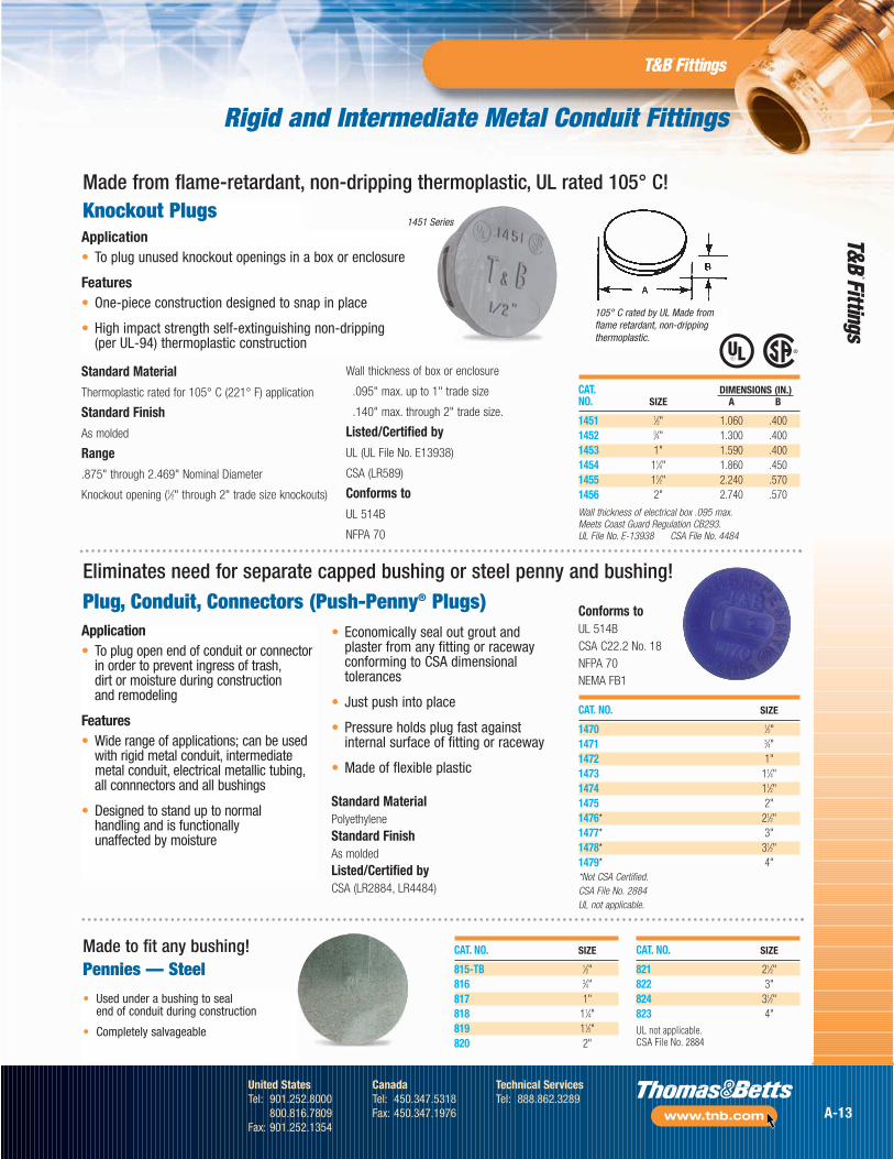
105° C rated by UL Made fromflame retardant, non-drippingthermoplastic.
CAT. DIMENSIONS (IN.)NO. SIZE A B
1451 1⁄2" 1.060 .4001452 3⁄4" 1.300 .4001453 1" 1.590 .4001454 11⁄4" 1.860 .4501455 11⁄2" 2.240 .5701456 2" 2.740 .570
Wall thickness of electrical box .095 max.Meets Coast Guard Regulation CB293.UL File No. E-13938 CSA File No. 4484
Made from flame-retardant, non-dripping thermoplastic, UL rated 105° C!
Application• To plug open end of conduit or connector
in order to prevent ingress of trash,dirt or moisture during construction and remodeling
Features• Wide range of applications; can be used
with rigid metal conduit, intermediatemetal conduit, electrical metallic tubing,all connnectors and all bushings
• Designed to stand up to normal handling and is functionally unaffected by moisture
• Used under a bushing to seal end of conduit during construction
• Completely salvageable
CAT. NO. SIZE
815-TB 1⁄2"816 3⁄4"817 1"818 11⁄4"819 11⁄2"820 2"
CAT. NO. SIZE
821 21⁄2"822 3"824 31⁄2"823 4"UL not applicable.CSA File No. 2884
Plug, Conduit, Connectors (Push-Penny® Plugs)Eliminates need for separate capped bushing or steel penny and bushing!
• Economically seal out grout andplaster from any fitting or racewayconforming to CSA dimensionaltolerances
• Just push into place
• Pressure holds plug fast againstinternal surface of fitting or raceway
• Made of flexible plastic
Made to fit any bushing!Pennies — Steel
CAT. NO. SIZE
1470 1⁄2"1471 3⁄4"1472 1"1473 11⁄4"1474 11⁄2"1475 2"1476* 21⁄2"1477* 3"1478* 31⁄2"1479* 4"*Not CSA Certified.CSA File No. 2884UL not applicable.
Standard MaterialPolyethyleneStandard FinishAs moldedListed/Certified byCSA (LR2884, LR4484)
Knockout PlugsApplication• To plug unused knockout openings in a box or enclosure
Features• One-piece construction designed to snap in place
• High impact strength self-extinguishing non-dripping (per UL-94) thermoplastic construction
1451 Series
Conforms toUL 514BCSA C22.2 No. 18NFPA 70NEMA FB1
Standard MaterialThermoplastic rated for 105° C (221° F) application
Standard FinishAs molded
Range.875" through 2.469" Nominal Diameter
Knockout opening (1⁄2" through 2" trade size knockouts)
Wall thickness of box or enclosure
.095" max. up to 1" trade size
.140" max. through 2" trade size.
Listed/Certified byUL (UL File No. E13938)
CSA (LR589)
Conforms toUL 514B
NFPA 70
A-13
United StatesTel: 901.252.8000
800.816.7809Fax: 901.252.1354
CanadaTel: 450.347.5318Fax: 450.347.1976
Technical ServicesTel: 888.862.3289
www.tnb.com
Rigid and Intermediate Metal Conduit Fittings
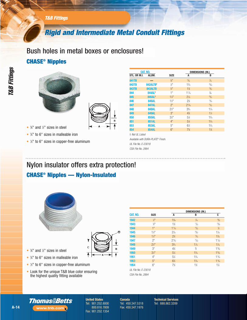
CAT. NO. DIMENSIONS (IN.)STL. OR M.I. ALUM. SIZE A B
841TB — 3⁄8" 15⁄167⁄16
842TB 842ALTB† 1⁄2" 19⁄1643⁄64
843TB 843ALTB 3⁄4" 13⁄8 19⁄32
844 844AL† 1" 111⁄163⁄64
845 845AL† 11⁄4" 21⁄3225⁄32
846 846AL 11⁄2" 23⁄8 13⁄16
847 847AL 2" 215⁄1631⁄32
848 848AL 21⁄2" 39⁄16 11⁄16
849 849AL 3" 43⁄8 11⁄4850 850AL 31⁄2" 51⁄8 15⁄16
851 851AL 4" 51⁄8 15⁄16
853 853AL 5" 61⁄2 15⁄16
854 854AL 6" 75⁄8 13⁄8
† Not UL Listed
Available with DURA-PLATE® Finish.
UL File No. E-23018
CSA File No. 2884
DIMENSIONS (IN.)CAT. NO. SIZE A B C
1942 1⁄2" 19⁄647⁄16
19⁄32
1943 3⁄4" 13⁄8 17⁄3223⁄32
1944 1" 111⁄1621⁄32
7⁄81945 11⁄4" 21⁄32
25⁄32 11⁄32
1946 11⁄2" 23⁄8 13⁄16 13⁄32
1947 2" 215⁄1631⁄32 111⁄32
1948 21⁄2" 39⁄16 11⁄16 17⁄16
1949 3" 43⁄8 1i 119⁄32
1950 31⁄2" 51⁄8 15⁄16 125⁄32
1951 4" 51⁄8 15⁄16 113⁄16
1953 5" 63⁄8 15⁄16 113⁄16
1954 6" 75⁄8 13⁄8 17⁄8
UL File No. E-23018
CSA File No. 2884
CHASE® Nipples
CHASE® Nipples — Nylon-Insulated
Bush holes in metal boxes or enclosures!
Nylon insulator offers extra protection!
• 3⁄8" and 1⁄2" sizes in steel
• 3⁄4" to 6" sizes in malleable iron
• 1⁄2" to 6" sizes in copper-free aluminum
• 3⁄8" and 1⁄2" sizes in steel
• 3⁄4" to 6" sizes in malleable iron
• 1⁄2" to 6" sizes in copper-free aluminum
• Look for the unique T&B blue color ensuringthe highest quality fitting available
A-14
United StatesTel: 901.252.8000
800.816.7809Fax: 901.252.1354
CanadaTel: 450.347.5318Fax: 450.347.1976
Technical ServicesTel: 888.862.3289
www.tnb.com
Rigid and Intermediate Metal Conduit Fittings
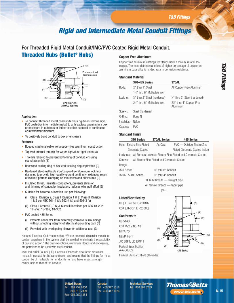
For Threaded Rigid Metal Conduit/IMC/PVC Coated Rigid Metal Conduit.
Application• To connect threaded metal conduit (ferrous rigid/non-ferrous rigid/
PVC coated/or intermediate metal) to a threadless opening in a box or enclosure in outdoors or indoor location exposed to continuous or intermittent moisture
• To positively bond conduit to box or enclosure
Features• Rugged steel/malleable iron/copper-free aluminum construction
• Tapered internal threads for water-tight/dust-tight union (A)
• Threads relieved to prevent bottoming of conduit, ensuring sound assembly (B)
• Recessed sealing ring at box end; sealing ring captivated (C)
• Hardened steel/malleable iron/copper-free aluminum locknutsdesigned to provide high-quality ground continuity; extended reach of locknut permits clamping on thin boxes and enclosures (D)
• Insulated throat, insulates conductors, prevents abrasion and thinning of conductor insulation, reduces wire pull effort (E)
• Suitable for hazardous location use per following:
(i) Class I Division 2, Class II Division 1 & 2, Class III Division 1 & 2 per NEC 501-4 (b); 502-4 (a) and 503-3 (a)
(ii) Class II Groups E, F, G, & Class III locations per CEC 18-202; 18-252; 18-302; 18-352
• PVC coated 485 Series
(i) Protects connector from extremely corrosive surroundings without affecting integrity of electrical grounding path (F)
(ii) Provided with overlapping sleeve for additional seal (G)
National Electrical Code® states that, “Where practical, dissimilar metals incontact anywhere in the system shall be avoided to eliminate the possibilityof galvanic action.” The only exceptions, aluminum fittings and enclosures,are permitted to be used with steel conduit.
Joint Industrial Council (JIC) Electrical Standards also forbid dissimilarmetals in contact for the same reason and require that the fittings for metalconduit be of malleable iron or ductile iron and have impact strengthcomparable to that of the conduit.
Threaded Hubs (Bullet® Hubs)
(B)
(C)
(E)
(A)
PredeterminedCompression
(D)
370 Series370AL Series
Copper-Free AluminumCopper free aluminum castings for fittings have a maximum of 0.4%copper. The most detrimental effect of higher percentage of copper onaluminum base alloy is its decrease in corrosion resistance.
Standard Material370-485 Series 370AL
Body: 1⁄2" thru 1" Steel All Copper-Free Aluminum
11⁄4" thru 6" Malleable Iron
Locknut: 1⁄2" thru 2" Steel (hardened) 1⁄2" thru 2" Steel (hardened)
21⁄2" thru 6" Malleable Iron 21⁄2" thru 4" Copper-Free Aluminum
Screws: Steel (hardened)
O-Ring: Buna N
Insulator: Nylon
Coating: PVC
Standard Finish370 Series 370AL Series 485 Series
Hub; Electro Zinc Plated As Cast PVC — Outside Electro Zinc
Chromate Coated Plated Chromate Coated Inside
Locknuts: All Ferrous Locknuts Electro Zinc Plated and Chromate Coated
Screws: All Electro Zinc Plated and Chromate Coated
Range:
370 Series 1⁄2" thru 6" Conduit
370AL & 485 Series 1⁄2" thru 4" Conduit
All hub threads — straight pipe
All female threads — taper pipe
(NPT)
Listed/Certified byUL (UL File No: E-23018)
CSA (LR-637, LR-23086)
Conforms toUL 514B
CSA C22.2 No. 18
NFPA 70
NEMA FB-1
JIC EGP1; JIC EMP 1
Federal Specification A-A-50553
Federal Standard H-28 (Threads)
(B)
(C)
(E)(D)
(G)
(F)
(A)
(G)
485 Series
A-15
United StatesTel: 901.252.8000
800.816.7809Fax: 901.252.1354
CanadaTel: 450.347.5318Fax: 450.347.1976
Technical ServicesTel: 888.862.3289
www.tnb.com
Rigid and Intermediate Metal Conduit Fittings
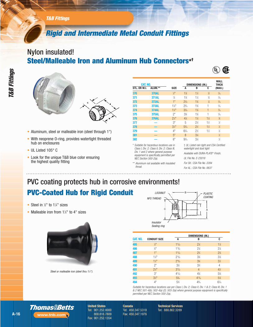
Nylon insulated!Steel/Malleable Iron and Aluminum Hub Connectors*†
PVC-Coated Hub for Rigid Conduit• Steel in 1⁄2" to 11⁄4" sizes
• Malleable iron from 11⁄2" to 4" sizes
DIMENSIONS (IN.)CAT. NO. CONDUIT SIZE A B C
485 1⁄2" 121⁄64 21⁄8 17⁄8486 3⁄4" 119⁄32 21⁄8 21⁄8487 1" 127⁄32 23⁄4 23⁄8488 11⁄4" 215⁄32 33⁄8 31⁄8489 11⁄2" 229⁄32 35⁄8 31⁄2490 2" 33⁄8 33⁄4 4491 21⁄2" 327⁄32 4 41⁄2492 3" 421⁄32 45⁄8 55⁄8493 31⁄2" 59⁄64 413⁄16 57⁄8494 4" 53⁄4 49⁄16 67⁄16
Suitable for hazardous locations use per Class I, Div. 2; Class II, Div. 1 & 2; Class III, Div. 1 & 2 NEC 501-4(b); 502-4(a) (2); 503-3(a) where general purpose equipment is specificallypermitted per NEC Section 500-2(a).
WALLCAT. NO. DIMENSIONS (IN.) THICK
STL. OR M.I. ALUM.** SIZE A B C (MAX.)
370 370AL 1⁄2" 13⁄8 11⁄4 3⁄4 5⁄16
371 371AL 3⁄4 15⁄8 11⁄4 3⁄4 5⁄16
372 372AL 1" 23⁄32 13⁄8 7⁄8 5⁄16
373 373AL 11⁄8" 29⁄16 15⁄8 1 5⁄16
374 374AL 11⁄2" 33⁄32 15⁄8 1 5⁄16
375 375AL 2" 35⁄8 15⁄8 1 5⁄16
376 376AL 21⁄2" 41⁄8 17⁄8 11⁄8 3⁄8377 — 3" 5 21⁄2 11⁄2 1⁄2378 — 31⁄2" 59⁄16 21⁄2 11⁄2 1⁄2379 — 4" 63⁄16 21⁄2 11⁄2 1⁄2381 — 5" 8 31⁄8 1⁄2382 — 6" 93⁄16 31⁄8 1⁄2
Steel or malleable iron (steel thru 11⁄4").
InsulatorSealing ring
NFS THREAD
LOCKNUT PLASTICCOATING
A
B
C
®
®
* Suitable for hazardous locations use inClass I, Div. 2; Class II, Div. 2; Class III,Div. 1 and 2 where general purposeequipment is specifically permitted perNEC Section 500-2(a).
** Aluminum not available with insulatedthroat.
† UL Listed rain tight and CSA Certifiedwatertight and dust tight
Available with DURA-PLATE® Finish.
UL File No. E-23018
For Stl.: CSA File No. 2284
For AL.: CSA File No. 0637
• Aluminum, steel or malleable iron (steel through 1")
• With neoprene O-ring, provides watertight threaded hub on enclosures
• UL Listed 105° C
• Look for the unique T&B blue color ensuring the highest quality fitting
PVC coating protects hub in corrosive environments!
A-16
United StatesTel: 901.252.8000
800.816.7809Fax: 901.252.1354
CanadaTel: 450.347.5318Fax: 450.347.1976
Technical ServicesTel: 888.862.3289
www.tnb.com
Rigid and Intermediate Metal Conduit Fittings
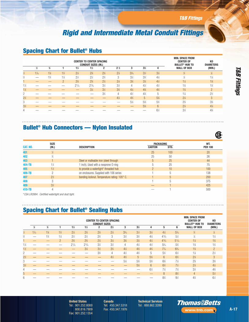
Spacing Chart for Bullet® HubsMIN. SPACE FROM
CENTER TO CENTER SPACING CENTER OF KOCONDUIT SIZES (IN.) BULLET® HUB TO DIAMETERS
1⁄2 3⁄4 1 11⁄4 11⁄2 2 2 1⁄2 3 31⁄2 4 WALL OF BOX (MIN.)1⁄2 17⁄16 15⁄8 13⁄4 21⁄8 23⁄8 25⁄8 27⁄8 35⁄16 31⁄2 37⁄8 3⁄4 7⁄83⁄4 — 13⁄4 17⁄8 21⁄4 21⁄2 23⁄4 3 31⁄2 33⁄4 41⁄8 7⁄8 11⁄81 — — 2 23⁄8 25⁄8 27⁄8 31⁄8 35⁄8 37⁄8 41⁄4 11⁄8 13⁄811⁄4 — — — 211⁄16 215⁄16 31⁄4 31⁄2 4 41⁄4 41⁄2 13⁄8 13⁄411⁄2 — — — — 31⁄8 31⁄2 33⁄4 41⁄8 43⁄8 43⁄4 15⁄8 22 — — — — — 33⁄4 4 41⁄2 43⁄4 5 17⁄8 21⁄221⁄2 — — — — — — 41⁄4 43⁄4 5 53⁄8 21⁄8 33 — — — — — — — 51⁄8 53⁄8 53⁄4 25⁄8 35⁄831⁄2 — — — — — — — — 55⁄8 6 27⁄8 41⁄84 — — — — — — — — — 61⁄4 31⁄4 45⁄8
SIZE PACKAGING WT.CAT. NO. (IN.) DESCRIPTION CARTON STD. PER 100
401 1⁄2 25 100 20402 3⁄4 25 50 26403 1 Steel or malleable iron (steel through 5 25 44404-TB 11⁄4 1 inch). Used with a neoprene O-ring 5 25 75405 11⁄2 to provide a watertight* threaded hub 2 10 100406-TB 2 on enclosures. Supplied with 106 series 1 5 138407 21⁄2 bonding locknut. Temperature rating: 105° C. 1 5 200408 3 1 5 375409 31⁄2 — 1 425410-TB 4 — 1 500
*CSA LR2884. Certified watertight and dust tight.
®
Spacing Chart for Bullet® Sealing HubsMIN. SPACE FROM
CENTER TO CENTER SPACING CENTER OF KOCONDUIT SIZES BULLET® HUB TO DIAMETERS
1⁄2 3⁄4 1 11⁄4 11⁄2 2 21⁄2 3 31⁄2 4 5 6 WALL OF BOX (MIN.)1⁄2 17⁄16 15⁄8 13⁄4 21⁄8 23⁄8 25⁄8 27⁄8 35⁄16 31⁄2 37⁄8 47⁄8 55⁄16
3⁄4 7⁄83⁄4 — 13⁄4 17⁄8 21⁄4 21⁄2 23⁄4 3 31⁄2 33⁄4 41⁄8 413⁄16 51⁄2 7⁄8 11⁄81 — — 2 23⁄8 25⁄8 27⁄8 31⁄8 35⁄8 37⁄8 41⁄4 415⁄16 511⁄16 11⁄8 13⁄811⁄4 — — — 211⁄16 215⁄16 31⁄4 31⁄2 4 41⁄4 41⁄2 55⁄16 53⁄4 13⁄8 13⁄411⁄2 — — — — 31⁄8 31⁄2 33⁄4 41⁄8 43⁄8 43⁄4 77⁄16 63⁄16 15⁄8 22 — — — — — 33⁄4 4 41⁄2 43⁄4 5 53⁄4 61⁄2 17⁄8 21⁄221⁄2 — — — — — — 41⁄4 43⁄4 5 53⁄8 6 63⁄4 21⁄8 33 — — — — — — — 51⁄8 53⁄8 53⁄4 63⁄8 71⁄8 25⁄8 35⁄831⁄2 — — — — — — — — 55⁄8 6 63⁄4 71⁄2 27⁄8 41⁄84 — — — — — — — — — 61⁄4 71⁄8 77⁄8 31⁄4 45⁄85 — — — — — — — — — — 8 83⁄4 4 51⁄26 — — — — — — — — — — 83⁄4 91⁄2 43⁄4 61⁄2
Bullet® Hub Connectors — Nylon Insulated
A-17
United StatesTel: 901.252.8000
800.816.7809Fax: 901.252.1354
CanadaTel: 450.347.5318Fax: 450.347.1976
Technical ServicesTel: 888.862.3289
www.tnb.com
Rigid and Intermediate Metal Conduit Fittings
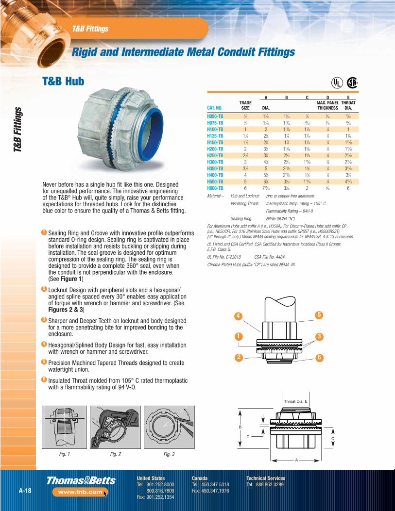
A B C D ETRADE MAX. PANEL THROAT
CAT. NO. SIZE DIA. THICKNESS DIA.
H050-TB 1⁄2 17⁄16 19⁄167⁄8 3⁄16
19⁄32
H075-TB 3⁄4 17⁄16 119⁄3229⁄32
3⁄1625⁄32
H100-TB 1 2 113⁄16 11⁄161⁄4 1
H125-TB 11⁄4 23⁄8 17⁄8 11⁄161⁄4 15⁄16
H150-TB 11⁄2 23⁄4 17⁄8 11⁄161⁄4 117⁄32
H200-TB 2 31⁄4 115⁄16 15⁄321⁄4 131⁄32
H250-TB 21⁄2 33⁄4 29⁄16 19⁄161⁄4 213⁄32
H300-TB 3 43⁄8 27⁄16 119⁄321⁄4 231⁄32
H350-TB 31⁄2 5 223⁄32 15⁄8 1⁄4 313⁄32
H400-TB 4 51⁄2 223⁄32 15⁄8 1⁄4 37⁄8H500-TB 5 67⁄8 31⁄32 115⁄16
1⁄4 415⁄16
H600-TB 6 711⁄16 35⁄32 2 5⁄16 6
Material – Hub and Locknut: zinc or copper-free aluminum
Insulating Throat: thermoplastic temp. rating – 105° C
Flammability Rating – 94V-0
Sealing Ring: Nitrile (BUNA “N”)
For Aluminum Hubs add suffix A (i.e., H050A). For Chrome-Plated Hubs add suffix CP (i.e., H050CP). For 316 Stainless Steel Hubs add suffix GRSST (i.e., H050GRSST).(1⁄2" through 2" only.) Meets NEMA sealing requirements for NEMA 3R, 4 & 13 enclosures.
UL Listed and CSA Certified. CSA Certified for hazardous locations Class II Groups E.F.G. Class III.
UL File No. E-23018 CSA File No. 4484
Chrome-Plated Hubs (suffix-“CP”) are rated NEMA 4X.
Throat Dia. E
D
®
®
Never before has a single hub fit like this one. Designed for unequalled performance. The innovative engineering of the T&B® Hub will, quite simply, raise your performanceexpectations for threaded hubs. Look for the distinctive blue color to ensure the quality of a Thomas & Betts fitting.
Sealing Ring and Groove with innovative profile outperformsstandard O-ring design. Sealing ring is captivated in placebefore installation and resists buckling or slipping duringinstallation. The seal groove is designed for optimumcompression of the sealing ring. The sealing ring isdesigned to provide a complete 360° seal, even when the conduit is not perpendicular with the enclosure.(See Figure 1)
Locknut Design with peripheral slots and a hexagonal/angled spline spaced every 30° enables easy application of torque with wrench or hammer and screwdriver. (SeeFigures 2 & 3)
Sharper and Deeper Teeth on locknut and body designedfor a more penetrating bite for improved bonding to theenclosure.
Hexagonal/Splined Body Design for fast, easy installationwith wrench or hammer and screwdriver.
Precision Machined Tapered Threads designed to createwatertight union.
Insulated Throat molded from 105° C rated thermoplasticwith a flammability rating of 94 V-O.
Fig. 1
4
1
2
5
3
6
Fig. 2 Fig. 3
T&B Hub
2
3
4
5
6
1
4
1
2 6
3
5
B
A
C
A-18
United StatesTel: 901.252.8000
800.816.7809Fax: 901.252.1354
CanadaTel: 450.347.5318Fax: 450.347.1976
Technical ServicesTel: 888.862.3289
www.tnb.com
Rigid and Intermediate Metal Conduit Fittings
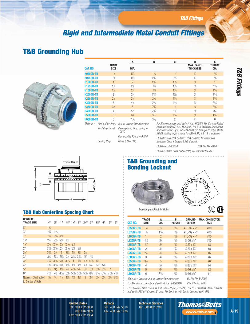
A B C D ETRADE MAX. PANEL THROAT
CAT. NO. SIZE DIA. THICKNESS DIA.
H050GR-TB 1⁄2 17⁄16 19⁄167⁄8 3⁄16
19⁄32
H075GR-TB 3⁄4 17⁄16 119⁄3229⁄32
3⁄1625⁄32
H100GR-TB 1 2 113⁄16 11⁄161⁄4 1
H125GR-TB 11⁄4 23⁄8 17⁄8 11⁄161⁄4 15⁄16
H150GR-TB 11⁄2 23⁄4 17⁄8 11⁄161⁄4 117⁄32
H200GR-TB 2 31⁄4 115⁄16 15⁄321⁄4 131⁄32
H250GR-TB 21⁄2 33⁄4 29⁄16 19⁄161⁄4 213⁄32
H300GR-TB 3 43⁄8 27⁄16 119⁄321⁄4 231⁄32
H350GR-TB 31⁄2 5 223⁄32 15⁄8 1⁄4 313⁄32
H400GR-TB 4 51⁄2 223⁄32 15⁄8 1⁄4 37⁄8H500GR-TB 5 67⁄8 31⁄32 115⁄16
1⁄4 415⁄16
H600GR-TB 6 711⁄16 35⁄32 2 5⁄16 6
TRADE A B GROUND MAX. CONDUCTORCAT. NO. SIZE DIA. HEIGHT SCREW SIZE
L050GR-TB 1⁄2 11⁄2 13⁄32 #10-32 x 1⁄4" #10L075GR-TB 3⁄4 111⁄16
13⁄32 #10-32 x 1⁄4" #10L100GR-TB 1 2 13⁄32 #10-32 x 1⁄4" #10L125GR-TB 11⁄4 23⁄8 15⁄32
1⁄4-20 x 1⁄4" #10L150GR-TB 11⁄2 23⁄4 15⁄32
1⁄4-20 x 5⁄16" #8L200GR-TB 2 31⁄4 15⁄32
1⁄4-20 x 5⁄16" #8L250GR-TB 21⁄2 33⁄4 11⁄16
1⁄4-20 x 5⁄16" #6L300GR-TB 3 43⁄8 23⁄32
1⁄4-20 x 5⁄16" #6L350GR-TB 31⁄2 5 23⁄32
1⁄4-20 x 5⁄16" #6L400GR-TB 4 51⁄2 23⁄32
1⁄4-20 x 5⁄16" #4L500GR-TB 5 65⁄8 23⁄32
3⁄8-16 x 3⁄8" #2L600GR-TB 6 711⁄16
23⁄323⁄8-16 x 3⁄8" #1
Material – Locknut: zinc or copper-free aluminum UL File No. E-3060
For Aluminum Locknuts add suffix A. (i.e., L050GRA) CSA File No. 4484
For Chrome-Plated Locknuts add suffix CP. (i.e., L050CP). For 316 Stainless Steel Locknutsadd suffix SST (1⁄2" through 2" only.) For Locknut with Lay In Lug add suffix GRL
A
®
®
T&B Hub Centerline Spacing ChartCONDUIT TRADE SIZE 1⁄2" 3⁄4" 1" 11⁄4" 11⁄2" 2" 21⁄2" 3" 31⁄2" 4" 5" 6"1⁄2" 19⁄16
3⁄4" 143⁄64 125⁄32
1" 127⁄32 161⁄64 21⁄811⁄4" 21⁄32 29⁄64 25⁄16 21⁄211⁄2" 27⁄32 221⁄64 21⁄2 211⁄16 27⁄82" 215⁄32 237⁄64 23⁄4 215⁄16 31⁄8 33⁄821⁄2" 223⁄32 2K 3 33⁄16 33⁄8 35⁄8 37⁄83" 31⁄32 39⁄64 35⁄16 31⁄2 311⁄16 315⁄16 43⁄16 41⁄231⁄2" 311⁄32 321⁄64 35⁄8 313⁄16 4 41⁄4 41⁄2 413⁄16 51⁄84" 319⁄32 345⁄64 37⁄8 41⁄16 41⁄4 41⁄2 43⁄4 51⁄16 53⁄8 55⁄85" 4s 3ç 49⁄16 43⁄4 415⁄16 53⁄16 57⁄16 53⁄4 61⁄16 65⁄16 76" 411⁄16 4J 431⁄32 55⁄32 511⁄32 519⁄32 527⁄32 65⁄32 615⁄32 623⁄32 713⁄32 713⁄16
Nearest Obstruction 27⁄3261⁄64 11⁄8 15⁄16 11⁄2 13⁄4 2 25⁄16 25⁄8 27⁄8 29⁄16 331⁄32
to Center of Hub
T&B Grounding Hub
T&B Grounding andBonding Locknut
Material – Hub and Locknut: zinc or copper-free aluminum
Insulating Throat: thermoplastic temp. rating – 105°C
Flammability Rating – 94V-0
Sealing Ring: Nitrile (BUNA “N”)
For Aluminum Hubs add suffix A (i.e., H050A). For Chrome-PlatedHubs add suffix CP (i.e., H050CP). For 316 Stainless Steel Hubsadd suffix GRSST (i.e., H050GRSST). (1⁄2" through 2" only.) MeetsNEMA sealing requirements for NEMA 3R, 4 & 13 enclosures.
UL Listed and CSA Certified. CSA Certified for hazardouslocations Class II Groups E.F.G. Class III.
UL File No. E-23018 CSA File No. 4484
Chrome-Plated Hubs (suffix-“CP”) are rated NEMA 4X.
Grounding Locknut for Hubs
Throat Dia. E
D
B
A
C
A-19
United StatesTel: 901.252.8000
800.816.7809Fax: 901.252.1354
CanadaTel: 450.347.5318Fax: 450.347.1976
Technical ServicesTel: 888.862.3289
www.tnb.com
Rigid and Intermediate Metal Conduit Fittings
HT, HTZ
HTGZ
Smootconduitstops
Knurled teethbite box
Convenientground screwoption
Spacesavingdesign
CaptiveO-ring
Plasticinsulatedthroat
Precisionmachinedthreads
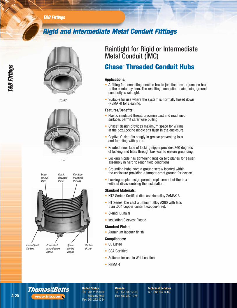
Applications:• A fitting for connecting junction box to junction box, or junction box
to the conduit system. The resulting connection maintaining groundcontinuity is raintight.
• Suitable for use where the system is normally hosed down (NEMA 4) for cleaning.
Features/Benefits:• Plastic insulated throat, precision cast and machined
surfaces permit safer wire pulling.
• Chase® design provides maximum space for wiring in the box.Locking nipple sits flush in the enclosure.
• Captive O-ring fits snugly in groove preventing loss and fumbling with parts.
• Knurled inner face of locking nipple provides 360 degrees of locking and bites through box wall to ensure grounding.
• Locking nipple has tightening lugs on two planes for easier assembly in hard to reach field conditions.
• Grounding hubs have a ground screw located within the enclosure providing a tamper-proof ground for device.
• Locking nipple design permits replacement of the box without disassembling the installation.
Standard Materials:• HTZ Series: Certified die cast zinc alloy ZAMAK 3.
• HT Series: Die cast aluminum alloy A360 with less than .004 copper content (copper-free).
• O-ring: Buna N
• Insulating Sleeves: Plastic
Standard Finish:• Aluminum lacquer finish
Compliances:• UL Listed
• CSA Certified
• Suitable for use in Wet Locations
• NEMA 4
Raintight for Rigid or Intermediate Metal Conduit (IMC)
Chase® Threaded Conduit Hubs
A-20
United StatesTel: 901.252.8000
800.816.7809Fax: 901.252.1354
CanadaTel: 450.347.5318Fax: 450.347.1976
Technical ServicesTel: 888.862.3289
www.tnb.com
Rigid and Intermediate Metal Conduit Fittings
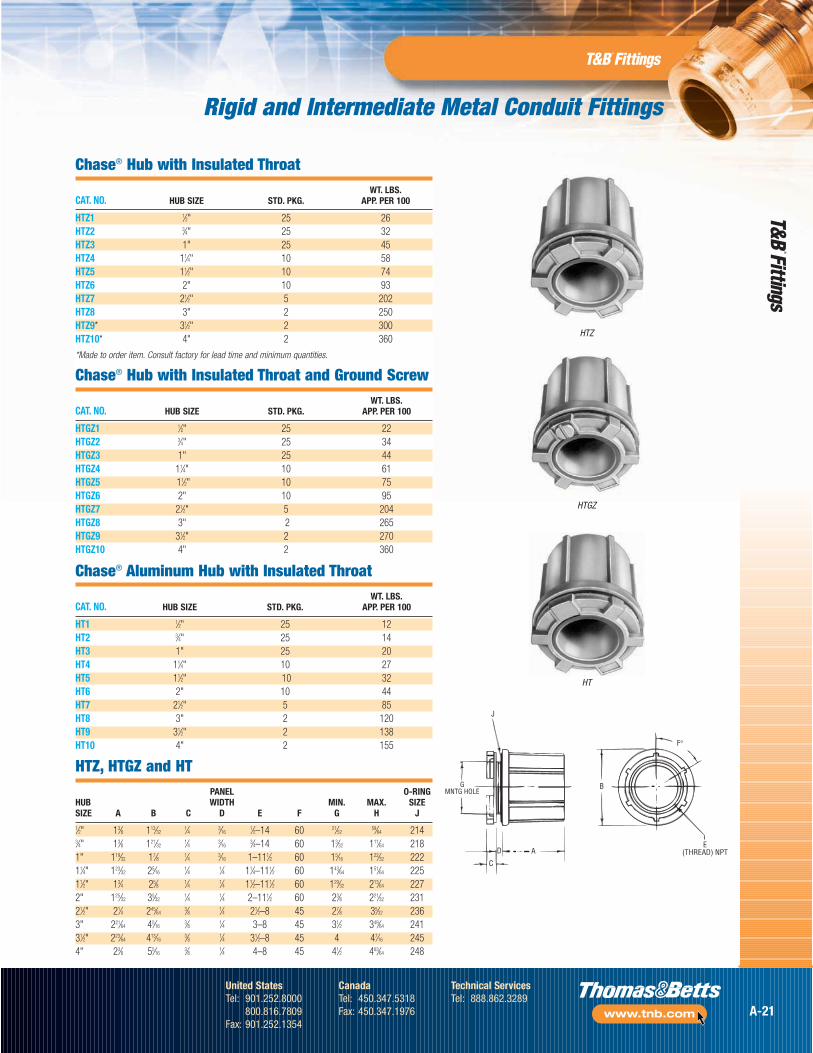
Chase® Hub with Insulated ThroatWT. LBS.
CAT. NO. HUB SIZE STD. PKG. APP. PER 100
HTZ1 1⁄2" 25 26HTZ2 3⁄4" 25 32HTZ3 1" 25 45HTZ4 11⁄4" 10 58HTZ5 11⁄2" 10 74HTZ6 2" 10 93HTZ7 21⁄2" 5 202HTZ8 3" 2 250HTZ9* 31⁄2" 2 300HTZ10* 4" 2 360
*Made to order item. Consult factory for lead time and minimum quantities.
Chase® Hub with Insulated Throat and Ground ScrewWT. LBS.
CAT. NO. HUB SIZE STD. PKG. APP. PER 100
HTGZ1 1⁄2" 25 22HTGZ2 3⁄4" 25 34HTGZ3 1" 25 44HTGZ4 11⁄4" 10 61HTGZ5 11⁄2" 10 75HTGZ6 2" 10 95HTGZ7 21⁄2" 5 204HTGZ8 3" 2 265HTGZ9 31⁄2" 2 270HTGZ10 4" 2 360
Chase® Aluminum Hub with Insulated ThroatWT. LBS.
CAT. NO. HUB SIZE STD. PKG. APP. PER 100
HT1 1⁄2" 25 12HT2 3⁄4" 25 14HT3 1" 25 20HT4 11⁄4" 10 27HT5 11⁄2" 10 32HT6 2" 10 44HT7 21⁄2" 5 85HT8 3" 2 120HT9 31⁄2" 2 138HT10 4" 2 155
HTZ, HTGZ and HTPANEL O-RING
HUB WIDTH MIN. MAX. SIZESIZE A B C D E F G H J1⁄2" 13⁄8 113⁄32
1⁄4 3⁄161⁄2–14 60 21⁄52
59⁄64 2143⁄4" 13⁄8 121⁄32
1⁄4 3⁄163⁄4–14 60 13⁄32 111⁄64 218
1" 119⁄32 17⁄8 1⁄4 3⁄16 1–111⁄2 60 15⁄16 122⁄32 22211⁄4" 123⁄32 25⁄16
1⁄4 1⁄4 11⁄4–111⁄2 60 143⁄64 151⁄64 22511⁄2" 13⁄4 25⁄8 1⁄4 1⁄4 11⁄2–111⁄2 60 129⁄32 213⁄64 2272" 125⁄32 35⁄32
1⁄4 1⁄4 2–111⁄2 60 23⁄8 221⁄32 23121⁄2" 21⁄4 245⁄64
3⁄8 1⁄4 21⁄2–8 45 27⁄8 35⁄32 2363" 221⁄64 45⁄16
3⁄8 1⁄4 3–8 45 31⁄2 349⁄64 24131⁄2" 223⁄64 413⁄16
3⁄8 1⁄4 31⁄2–8 45 4 47⁄16 2454" 23⁄8 55⁄16
3⁄8 1⁄4 4–8 45 41⁄2 463⁄64 248
GMNTG HOLE
C
D A
J
B
F°
E(THREAD) NPT
HTZ
HTGZ
HT
A-21
United StatesTel: 901.252.8000
800.816.7809Fax: 901.252.1354
CanadaTel: 450.347.5318Fax: 450.347.1976
Technical ServicesTel: 888.862.3289
www.tnb.com
Rigid and Intermediate Metal Conduit Fittings
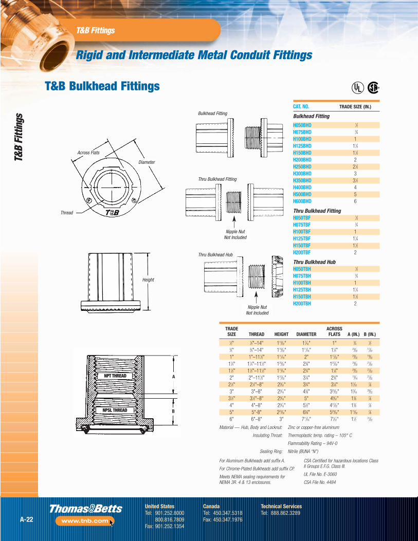
CAT. NO. TRADE SIZE (IN.)
Bulkhead Fitting
H050BHD 1⁄2H075BHD 3⁄4H100BHD 1H125BHD 11⁄4H150BHD 11⁄2H200BHD 2H250BHD 21⁄2H300BHD 3H350BHD 31⁄2H400BHD 4H500BHD 5H600BHD 6
Thru Bulkhead FittingH050TBF 1⁄2H075TBF 3⁄4H100TBF 1H125TBF 11⁄4H150TBF 11⁄2H200TBF 2
Thru Bulkhead HubH050TBH 1⁄2H075TBH 3⁄4H100TBH 1H125TBH 11⁄4H150TBH 11⁄2H200TBH 2
Across Flats
Height
Diameter
Thread
Nipple NutNot Included
Nipple NutNot Included
®
®T&B Bulkhead Fittings
TRADE ACROSSSIZE THREAD HEIGHT DIAMETER FLATS A (IN.) B (IN.)
1⁄2" 1⁄2"–14" 113⁄32" 17⁄16" 1" 3⁄4 1⁄23⁄4" 3⁄4"–14" 115⁄32" 111⁄16" 11⁄4" 25⁄32
17⁄32
1" 1"–111⁄2" 111⁄16" 2" 117⁄32" 29⁄3219⁄32
11⁄4" 11⁄4"–111⁄2" 125⁄32" 23⁄8" 127⁄32" 29⁄3221⁄32
11⁄2" 11⁄2"–111⁄2" 113⁄16" 23⁄4" 11⁄8" 29⁄3221⁄32
2" 2"–111⁄2" 127⁄32" 31⁄4" 25⁄8" 15⁄1621⁄32
21⁄2" 21⁄2"–8" 29⁄32" 33⁄4" 31⁄8" 17⁄327⁄8
3" 3"–8" 29⁄16" 43⁄8" 325⁄32" 13⁄1629⁄32
31⁄2" 31⁄2"–8" 29⁄16" 5" 49⁄32" 13⁄8 7⁄84" 4"–8" 29⁄16" 51⁄2" 427⁄32" 13⁄8 7⁄85" 5"-8" 223⁄32" 65⁄8" 529⁄32" 115⁄32
7⁄86" 6"–8" 3" 711⁄16" 71⁄32" 11⁄2 31⁄32
Material — Hub, Body and Locknut: Zinc or copper-free aluminum
Insulating Throat: Thermoplastic temp. rating – 105° C
Flammability Rating – 94V-0
Sealing Ring: Nitrile (BUNA “N”)
For Aluminum Bulkheads add suffix A.
For Chrome-Plated Bulkheads add suffix CP.
Meets NEMA sealing requirements forNEMA 3R. 4 & 13 enclosures.
CSA Certified for hazardous locations ClassII Groups E.F.G. Class III.
UL File No. E-3060
CSA File No. 4484
Bulkhead Fitting
Thru Bulkhead Fitting
Thru Bulkhead Hub
A
B
NPT THREAD
NPSL THREAD
A-22
United StatesTel: 901.252.8000
800.816.7809Fax: 901.252.1354
CanadaTel: 450.347.5318Fax: 450.347.1976
Technical ServicesTel: 888.862.3289
www.tnb.com
Rigid and Intermediate Metal Conduit Fittings
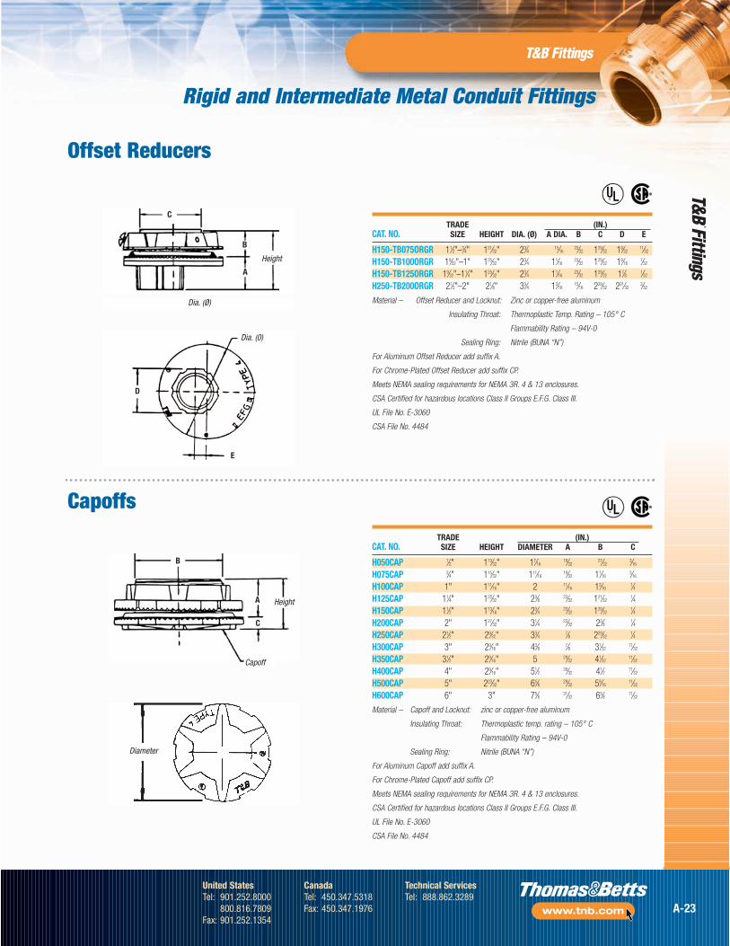
TRADE (IN.)CAT. NO. SIZE HEIGHT DIA. (Ø) A DIA. B C D E
H150-TB075ORGR 11⁄2"–3⁄4" 121⁄32" 23⁄4 15⁄1623⁄32 129⁄32 19⁄32
11⁄32
H150-TB100ORGR 19⁄32"–1" 125⁄32" 23⁄4 11⁄1623⁄32 129⁄32 19⁄16
7⁄32
H150-TB125ORGR 19⁄32"–11⁄4" 125⁄32" 23⁄4 11⁄1623⁄32 129⁄32 17⁄8 1⁄32
H250-TB200ORGR 21⁄2"–2" 21⁄8" 33⁄4 13⁄1615⁄16 229⁄32 221⁄32
3⁄32
Material – Offset Reducer and Locknut: Zinc or copper-free aluminum
Insulating Throat: Thermoplastic Temp. Rating – 105° C
Flammability Rating – 94V-0
Sealing Ring: Nitrile (BUNA “N”)
For Aluminum Offset Reducer add suffix A.
For Chrome-Plated Offset Reducer add suffix CP.
Meets NEMA sealing requirements for NEMA 3R. 4 & 13 enclosures.
CSA Certified for hazardous locations Class II Groups E.F.G. Class III.
UL File No. E-3060
CSA File No. 4484
Dia. (Ø)
Height
Capoff
Height
Dia. (0)
Diameter
A
C
B
C
B
A
E
D
®
®
®
®
TRADE (IN.)CAT. NO. SIZE HEIGHT DIAMETER A B C
H050CAP 1⁄2" 113⁄32" 17⁄1619⁄32
27⁄323⁄16
H075CAP 3⁄4" 115⁄32" 111⁄1619⁄32 11⁄16
3⁄16
H100CAP 1" 111⁄16" 2 11⁄16 13⁄161⁄4
H125CAP 11⁄4" 125⁄32" 23⁄8 23⁄32 121⁄321⁄4
H150CAP 11⁄2" 113⁄16" 23⁄4 23⁄32 129⁄321⁄4
H200CAP 2" 127⁄32" 31⁄4 23⁄32 23⁄8 1⁄4H250CAP 21⁄2" 29⁄32" 33⁄4 7⁄8 229⁄32
1⁄4H300CAP 3" 29⁄16" 43⁄8 7⁄8 31⁄32
11⁄32
H350CAP 31⁄2" 29⁄16" 5 29⁄32 41⁄3211⁄32
H400CAP 4" 29⁄16" 51⁄2 29⁄32 41⁄2 11⁄32
H500CAP 5" 223⁄32" 65⁄8 29⁄32 59⁄1611⁄32
H600CAP 6" 3" 75⁄8 31⁄32 65⁄8 11⁄32
Material – Capoff and Locknut: zinc or copper-free aluminum
Insulating Throat: Thermoplastic temp. rating – 105° C
Flammability Rating – 94V-0
Sealing Ring: Nitrile (BUNA “N”)
For Aluminum Capoff add suffix A.
For Chrome-Plated Capoff add suffix CP.
Meets NEMA sealing requirements for NEMA 3R. 4 & 13 enclosures.
CSA Certified for hazardous locations Class II Groups E.F.G. Class III.
UL File No. E-3060
CSA File No. 4484
Offset Reducers
Capoffs
A-23
United StatesTel: 901.252.8000
800.816.7809Fax: 901.252.1354
CanadaTel: 450.347.5318Fax: 450.347.1976
Technical ServicesTel: 888.862.3289
www.tnb.com
Rigid and Intermediate Metal Conduit Fittings
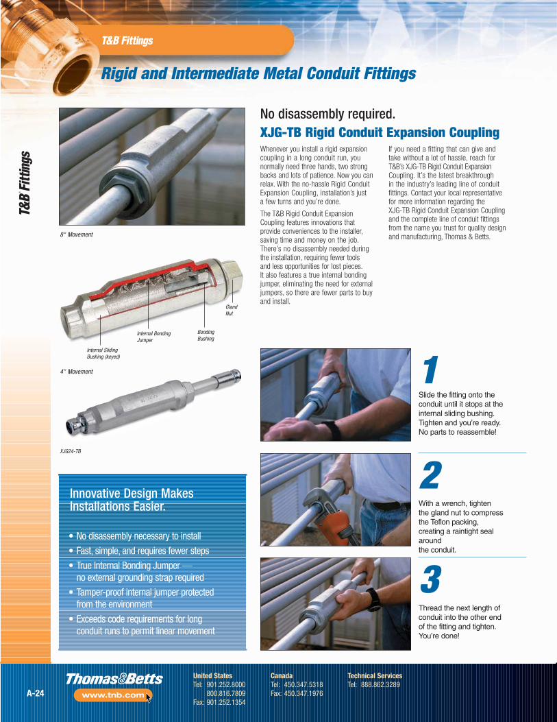
XJG-TB Rigid Conduit Expansion CouplingWhenever you install a rigid expansioncoupling in a long conduit run, younormally need three hands, two strongbacks and lots of patience. Now you canrelax. With the no-hassle Rigid ConduitExpansion Coupling, installation’s just a few turns and you’re done.
The T&B Rigid Conduit ExpansionCoupling features innovations that provide conveniences to the installer,saving time and money on the job.There’s no disassembly needed duringthe installation, requiring fewer tools and less opportunities for lost pieces.It also features a true internal bondingjumper, eliminating the need for externaljumpers, so there are fewer parts to buyand install.
If you need a fitting that can give andtake without a lot of hassle, reach forT&B’s XJG-TB Rigid Conduit ExpansionCoupling. It’s the latest breakthrough in the industry’s leading line of conduitfittings. Contact your local representativefor more information regarding the XJG-TB Rigid Conduit Expansion Couplingand the complete line of conduit fittingsfrom the name you trust for quality designand manufacturing, Thomas & Betts.8" Movement
Innovative Design MakesInstallations Easier.
• No disassembly necessary to install
• Fast, simple, and requires fewer steps
• True Internal Bonding Jumper — no external grounding strap required
• Tamper-proof internal jumper protected from the environment
• Exceeds code requirements for long conduit runs to permit linear movement
1Slide the fitting onto theconduit until it stops at theinternal sliding bushing.Tighten and you’re ready.No parts to reassemble!
2With a wrench, tighten the gland nut to compressthe Teflon packing,creating a raintight sealaround the conduit.
3Thread the next length ofconduit into the other endof the fitting and tighten.You’re done!
XJG24-TB
4" Movement
Internal SlidingBushing (keyed)
Internal BondingJumper
BondingBushing
GlandNut
No disassembly required.
A-24
United StatesTel: 901.252.8000
800.816.7809Fax: 901.252.1354
CanadaTel: 450.347.5318Fax: 450.347.1976
Technical ServicesTel: 888.862.3289
www.tnb.com
Rigid and Intermediate Metal Conduit Fittings
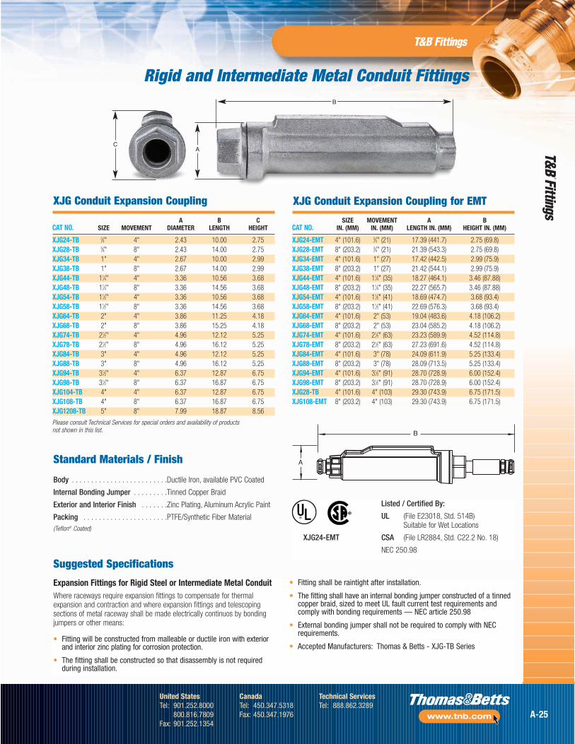
A B CCAT NO. SIZE MOVEMENT DIAMETER LENGTH HEIGHT
XJG24-TB 3⁄4" 4" 2.43 10.00 2.75XJG28-TB 3⁄4" 8" 2.43 14.00 2.75XJG34-TB 1" 4" 2.67 10.00 2.99XJG38-TB 1" 8" 2.67 14.00 2.99XJG44-TB 11⁄4" 4" 3.36 10.56 3.68XJG48-TB 11⁄4" 8" 3.36 14.56 3.68XJG54-TB 11⁄2" 4" 3.36 10.56 3.68XJG58-TB 11⁄2" 8" 3.36 14.56 3.68XJG64-TB 2" 4" 3.86 11.25 4.18XJG68-TB 2" 8" 3.86 15.25 4.18XJG74-TB 21⁄2" 4" 4.96 12.12 5.25XJG78-TB 21⁄2" 8" 4.96 16.12 5.25XJG84-TB 3" 4" 4.96 12.12 5.25XJG88-TB 3" 8" 4.96 16.12 5.25XJG94-TB 31⁄2" 4" 6.37 12.87 6.75XJG98-TB 31⁄2" 8" 6.37 16.87 6.75XJG104-TB 4" 4" 6.37 12.87 6.75XJG108-TB 4" 8" 6.37 16.87 6.75XJG1208-TB 5" 8" 7.99 18.87 8.56
Please consult Technical Services for special orders and availability of products not shown in this list.
Expansion Fittings for Rigid Steel or Intermediate Metal ConduitWhere raceways require expansion fittings to compensate for thermalexpansion and contraction and where expansion fittings and telescopingsections of metal raceway shall be made electrically continuos by bondingjumpers or other means:
• Fitting will be constructed from malleable or ductile iron with exteriorand interior zinc plating for corrosion protection.
• The fitting shall be constructed so that disassembly is not requiredduring installation.
• Fitting shall be raintight after installation.
• The fitting shall have an internal bonding jumper constructed of a tinnedcopper braid, sized to meet UL fault current test requirements andcomply with bonding requirements — NEC article 250.98
• External bonding jumper shall not be required to comply with NECrequirements.
• Accepted Manufacturers: Thomas & Betts - XJG-TB Series
Standard Materials / Finish
Body . . . . . . . . . . . . . . . . . . . . . . . . .Ductile Iron, available PVC Coated
Internal Bonding Jumper . . . . . . . . .Tinned Copper Braid
Exterior and Interior Finish . . . . . . .Zinc Plating, Aluminum Acrylic Paint
Packing . . . . . . . . . . . . . . . . . . . . . .PTFE/Synthetic Fiber Material(Teflon® Coated)
C
B
A
XJG Conduit Expansion Coupling XJG Conduit Expansion Coupling for EMT
SIZE MOVEMENT A BCAT NO. IN. (MM) IN. (MM) LENGTH IN. (MM) HEIGHT IN. (MM)
XJG24-EMT 4" (101.6) 3⁄4" (21) 17.39 (441.7) 2.75 (69.8)XJG28-EMT 8" (203.2) 3⁄4" (21) 21.39 (543.3) 2.75 (69.8)XJG34-EMT 4" (101.6) 1" (27) 17.42 (442.5) 2.99 (75.9)XJG38-EMT 8" (203.2) 1" (27) 21.42 (544.1) 2.99 (75.9)XJG44-EMT 4" (101.6) 11⁄4" (35) 18.27 (464.1) 3.46 (87.88)XJG48-EMT 8" (203.2) 11⁄4" (35) 22.27 (565.7) 3.46 (87.88)XJG54-EMT 4" (101.6) 11⁄2" (41) 18.69 (474.7) 3.68 (93.4)XJG58-EMT 8" (203.2) 11⁄2" (41) 22.69 (576.3) 3.68 (93.4)XJG64-EMT 4" (101.6) 2" (53) 19.04 (483.6) 4.18 (106.2)XJG68-EMT 8" (203.2) 2" (53) 23.04 (585.2) 4.18 (106.2)XJG74-EMT 4" (101.6) 21⁄2" (63) 23.23 (589.9) 4.52 (114.8)XJG78-EMT 8" (203.2) 21⁄2" (63) 27.23 (691.6) 4.52 (114.8)XJG84-EMT 4" (101.6) 3" (78) 24.09 (611.9) 5.25 (133.4)XJG88-EMT 8" (203.2) 3" (78) 28.09 (713.5) 5.25 (133.4)XJG94-EMT 4" (101.6) 31⁄2" (91) 28.70 (728.9) 6.00 (152.4)XJG98-EMT 8" (203.2) 31⁄2" (91) 28.70 (728.9) 6.00 (152.4)XJG28-TB 4" (101.6) 4" (103) 29.30 (743.9) 6.75 (171.5)XJG108-EMT 8" (203.2) 4" (103) 29.30 (743.9) 6.75 (171.5)
A
B
Suggested Specifications
Listed / Certified By:
UL (File E23018, Std. 514B) Suitable for Wet Locations
XJG24-EMT CSA (File LR2884, Std. C22.2 No. 18)
NEC 250.98
®®
A
B
A-25
United StatesTel: 901.252.8000
800.816.7809Fax: 901.252.1354
CanadaTel: 450.347.5318Fax: 450.347.1976
Technical ServicesTel: 888.862.3289
www.tnb.com
8123 Series
8120 Series
8130 Series
Rigid and Intermediate Metal Conduit Fittings
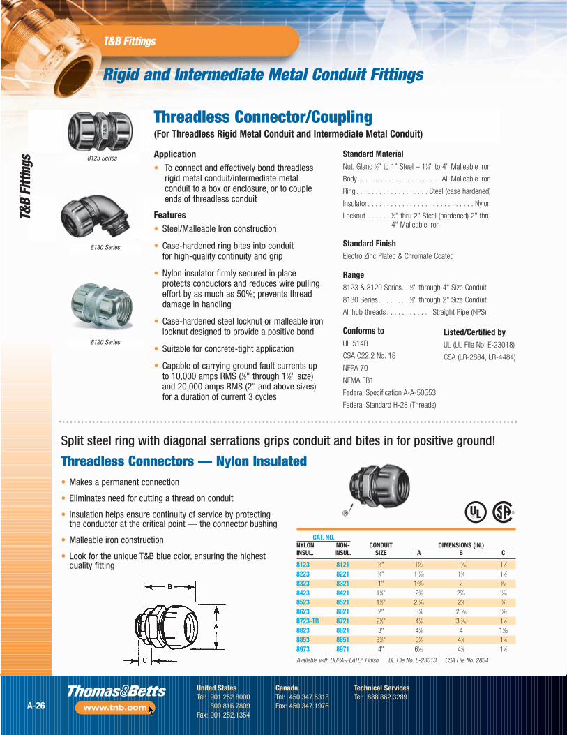
Threadless Connector/Coupling(For Threadless Rigid Metal Conduit and Intermediate Metal Conduit)
CAT. NO.NYLON NON- CONDUIT DIMENSIONS (IN.)INSUL. INSUL. SIZE A B C
8123 8121 1⁄2" 17⁄32 111⁄16 11⁄28223 8221 3⁄4" 117⁄32 13⁄4 11⁄28323 8321 1" 129⁄32 2 9⁄16
8423 8421 11⁄4" 23⁄8 27⁄1611⁄16
8523 8521 11⁄2" 211⁄16 25⁄8 3⁄48623 8621 2" 31⁄4 213⁄16
27⁄32
8723-TB 8721 21⁄2" 41⁄8 313⁄16 11⁄88823 8821 3" 47⁄8 4 17⁄32
8853 8851 31⁄2" 51⁄2 41⁄8 11⁄88973 8971 4" 61⁄32 47⁄8 11⁄8
Available with DURA-PLATE® Finish. UL File No. E-23018 CSA File No. 2884
• Makes a permanent connection
• Eliminates need for cutting a thread on conduit
• Insulation helps ensure continuity of service by protectingthe conductor at the critical point — the connector bushing
• Malleable iron construction
• Look for the unique T&B blue color, ensuring the highestquality fitting
Split steel ring with diagonal serrations grips conduit and bites in for positive ground!
Threadless Connectors — Nylon Insulated
Application• To connect and effectively bond threadless
rigid metal conduit/intermediate metalconduit to a box or enclosure, or to coupleends of threadless conduit
Features• Steel/Malleable Iron construction
• Case-hardened ring bites into conduit for high-quality continuity and grip
• Nylon insulator firmly secured in placeprotects conductors and reduces wire pullingeffort by as much as 50%; prevents threaddamage in handling
• Case-hardened steel locknut or malleable ironlocknut designed to provide a positive bond
• Suitable for concrete-tight application
• Capable of carrying ground fault currents upto 10,000 amps RMS (1⁄2" through 11⁄2" size)and 20,000 amps RMS (2" and above sizes)for a duration of current 3 cycles
Standard MaterialNut, Gland 1⁄2" to 1" Steel – 11⁄4" to 4" Malleable Iron
Body . . . . . . . . . . . . . . . . . . . . . . All Malleable Iron
Ring . . . . . . . . . . . . . . . . . . . Steel (case hardened)
Insulator . . . . . . . . . . . . . . . . . . . . . . . . . . . . Nylon
Locknut . . . . . . 1⁄2" thru 2" Steel (hardened) 2" thru 4" Malleable Iron
Standard FinishElectro Zinc Plated & Chromate Coated
Range8123 & 8120 Series. . 1⁄2" through 4" Size Conduit
8130 Series . . . . . . . . 1⁄2" through 2" Size Conduit
All hub threads . . . . . . . . . . . . Straight Pipe (NPS)
Conforms toUL 514B
CSA C22.2 No. 18
NFPA 70
NEMA FB1
Federal Specification A-A-50553
Federal Standard H-28 (Threads)
Listed/Certified byUL (UL File No: E-23018)
CSA (LR-2884, LR-4484)
A-26
United StatesTel: 901.252.8000
800.816.7809Fax: 901.252.1354
CanadaTel: 450.347.5318Fax: 450.347.1976
Technical ServicesTel: 888.862.3289
www.tnb.com
Rigid and Intermediate Metal Conduit Fittings
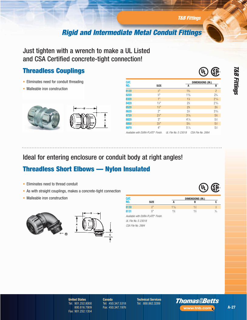
CAT. DIMENSIONS (IN.)NO. SIZE A B
8120 1⁄2" 19⁄32 28220 3⁄4" 119⁄32 25⁄16
8320 1" 17⁄8 211⁄16
8420 11⁄4" 23⁄8 213⁄16
8520 11⁄2" 25⁄8 35⁄88620 2" 31⁄4 313⁄16
8720 21⁄2" 315⁄16 53⁄88820 3" 411⁄16 51⁄28850 31⁄2" 53⁄16 51⁄28970 4" 511⁄16 51⁄2
Available with DURA-PLATE® Finish. UL File No. E-23018 CSA File No. 2884
CAT. DIMENSIONS (IN.)NO. SIZE A B C
8130 1⁄2" 111⁄32 11⁄2 1⁄28131 3⁄4" 15⁄8 13⁄4 9⁄16
Available with DURA-PLATE® Finish.
UL File No. E-23018
CSA File No. 2884
• Eliminates need for conduit threading
• Malleable iron construction
Just tighten with a wrench to make a UL Listed and CSA Certified concrete-tight connection!
Threadless Couplings
Ideal for entering enclosure or conduit body at right angles!
Threadless Short Elbows — Nylon Insulated
• Eliminates need to thread conduit
• As with straight couplings, makes a concrete-tight connection
• Malleable iron construction
A-27
United StatesTel: 901.252.8000
800.816.7809Fax: 901.252.1354
CanadaTel: 450.347.5318Fax: 450.347.1976
Technical ServicesTel: 888.862.3289
www.tnb.com
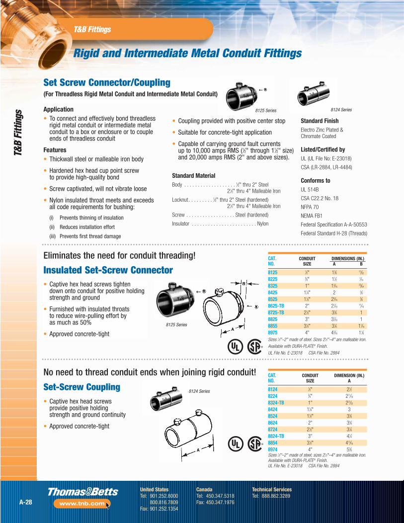
Application• To connect and effectively bond threadless
rigid metal conduit or intermediate metalconduit to a box or enclosure or to coupleends of threadless conduit
Features• Thickwall steel or malleable iron body
• Hardened hex head cup point screwto provide high-quality bond
• Screw captivated, will not vibrate loose
• Nylon insulated throat meets and exceedsall code requirements for bushing:
(i) Prevents thinning of insulation
(ii) Reduces installation effort
(iii) Prevents first thread damage
• Coupling provided with positive center stop
• Suitable for concrete-tight application
• Capable of carrying ground fault currentsup to 10,000 amps RMS (1⁄2" through 11⁄2" size)and 20,000 amps RMS (2" and above sizes).
Standard MaterialBody . . . . . . . . . . . . . . . . . . . 1⁄2" thru 2" Steel
21⁄2" thru 4" Malleable Iron
Locknut . . . . . . . . . 1⁄2" thru 2" Steel (hardened)21⁄2" thru 4" Malleable Iron
Screw . . . . . . . . . . . . . . . . . . Steel (hardened)
Insulator . . . . . . . . . . . . . . . . . . . . . . . . Nylon
Standard FinishElectro Zinc Plated &Chromate Coated
Listed/Certified byUL (UL File No: E-23018)
CSA (LR-2884, LR-4484)
Conforms toUL 514B
CSA C22.2 No. 18
NFPA 70
NEMA FB1
Federal Specification A-A-50553
Federal Standard H-28 (Threads)
Rigid and Intermediate Metal Conduit Fittings
Set Screw Connector/Coupling(For Threadless Rigid Metal Conduit and Intermediate Metal Conduit)
8125 Series
• Captive hex head screws tighten down onto conduit for positive holdingstrength and ground
• Furnished with insulated throats to reduce wire-pulling effort by as much as 50%
• Approved concrete-tight
CAT. CONDUIT DIMENSIONS (IN.)NO. SIZE A B
8125 1⁄2" 13⁄8 13⁄32
8225 3⁄4" 11⁄2 7⁄16
8325 1" 13⁄1635⁄64
8425 11⁄4" 2 5⁄88525 11⁄2" 25⁄16
5⁄88625-TB 2" 27⁄16
11⁄16
8725-TB 21⁄2" 33⁄8 18825 3" 37⁄16 18855 31⁄2" 37⁄8 11⁄16
8975 4" 43⁄16 11⁄8Sizes 1⁄2"–2" made of steel. Sizes 21⁄2"–4" are malleable iron.Available with DURA-PLATE® Finish.UL File No. E-23018 CSA File No. 2884
Eliminates the need for conduit threading!
Insulated Set-Screw Connector
No need to thread conduit ends when joining rigid conduit!
Set-Screw CouplingCAT. CONDUIT DIMENSION (IN.)NO. SIZE A
8124 1⁄2" 21⁄28224 3⁄4" 211⁄16
8324-TB 1" 227⁄32
8424 11⁄4" 38524 11⁄2" 33⁄88624 2" 35⁄88724 21⁄2" 37⁄88824-TB 3" 41⁄48854 31⁄2" 415⁄16
8974 4" 53⁄8Sizes 1⁄2"–2" made of steel; sizes 21⁄2"–4" are malleable iron.Available with DURA-PLATE® Finish.UL File No. E-23018 CSA File No. 2884
8124 Series
8125 Series
8124 Series
• Captive hex head screws provide positive holding strength and ground continuity
• Approved concrete-tight
A-28
United StatesTel: 901.252.8000
800.816.7809Fax: 901.252.1354
CanadaTel: 450.347.5318Fax: 450.347.1976
Technical ServicesTel: 888.862.3289
www.tnb.com
Rigid and Intermediate Metal Conduit Fittings
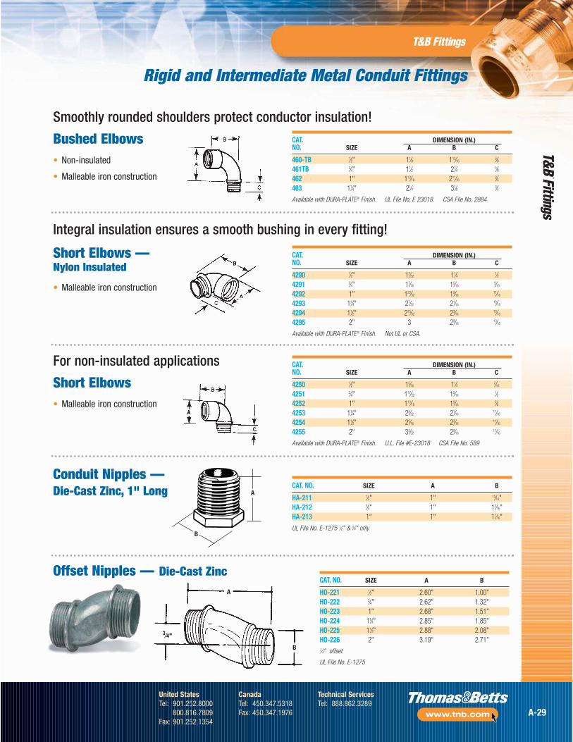
CAT. DIMENSION (IN.)NO. SIZE A B C
460-TB 1⁄2" 11⁄8 113⁄165⁄8
461TB 3⁄4" 11⁄2 21⁄4 5⁄8462 1" 113⁄16 211⁄16
3⁄4463 11⁄4" 21⁄4 31⁄8 3⁄4
Available with DURA-PLATE® Finish. UL File No. E 23018. CSA File No. 2884
Integral insulation ensures a smooth bushing in every fitting!
Short Elbows —Nylon Insulated
• Malleable iron construction
For non-insulated applications
Short Elbows• Malleable iron construction
CAT. DIMENSION (IN.)NO. SIZE A B C
4290 1⁄2" 17⁄32 11⁄4 1⁄24291 3⁄4" 17⁄16 15⁄16
9⁄16
4292 1" 123⁄32 19⁄1611⁄16
4293 11⁄4" 27⁄32 21⁄1613⁄16
4294 11⁄2" 215⁄32 23⁄1613⁄16
4295 2" 3 29⁄1613⁄16
Available with DURA-PLATE® Finish. Not UL or CSA.
CAT. DIMENSION (IN.)NO. SIZE A B C
4250 1⁄2" 15⁄16 11⁄4 7⁄16
4251 3⁄4" 117⁄32 15⁄161⁄2
4252 1" 113⁄16 19⁄165⁄8
4253 11⁄4" 29⁄32 21⁄1611⁄16
4254 11⁄2" 29⁄16 23⁄1611⁄16
4255 2" 33⁄32 29⁄1611⁄16
Available with DURA-PLATE® Finish. U.L. File #E-23018 CSA File No. 589
Conduit Nipples —Die-Cast Zinc, 1" Long CAT. NO. SIZE A B
HA-211 1⁄2" 1" 15⁄16"HA-212 3⁄4" 1" 13⁄16"HA-213 1" 1" 17⁄16"
UL File No. E-1275 1⁄2" & 3⁄4" onlyB
A
Offset Nipples — Die-Cast Zinc
A
B
3⁄4"
CAT. NO. SIZE A B
HO-221 1⁄2" 2.60" 1.00"HO-222 3⁄4" 2.62" 1.32"HO-223 1" 2.68" 1.51"HO-224 11⁄4" 2.85" 1.85"HO-225 11⁄2" 2.88" 2.08"HO-226 2" 3.19" 2.71"3⁄4" offset
UL File No. E-1275
Smoothly rounded shoulders protect conductor insulation!
Bushed Elbows• Non-insulated
• Malleable iron construction
A-29
United StatesTel: 901.252.8000
800.816.7809Fax: 901.252.1354
CanadaTel: 450.347.5318Fax: 450.347.1976
Technical ServicesTel: 888.862.3289
www.tnb.com
Rigid and Intermediate Metal Conduit Fittings
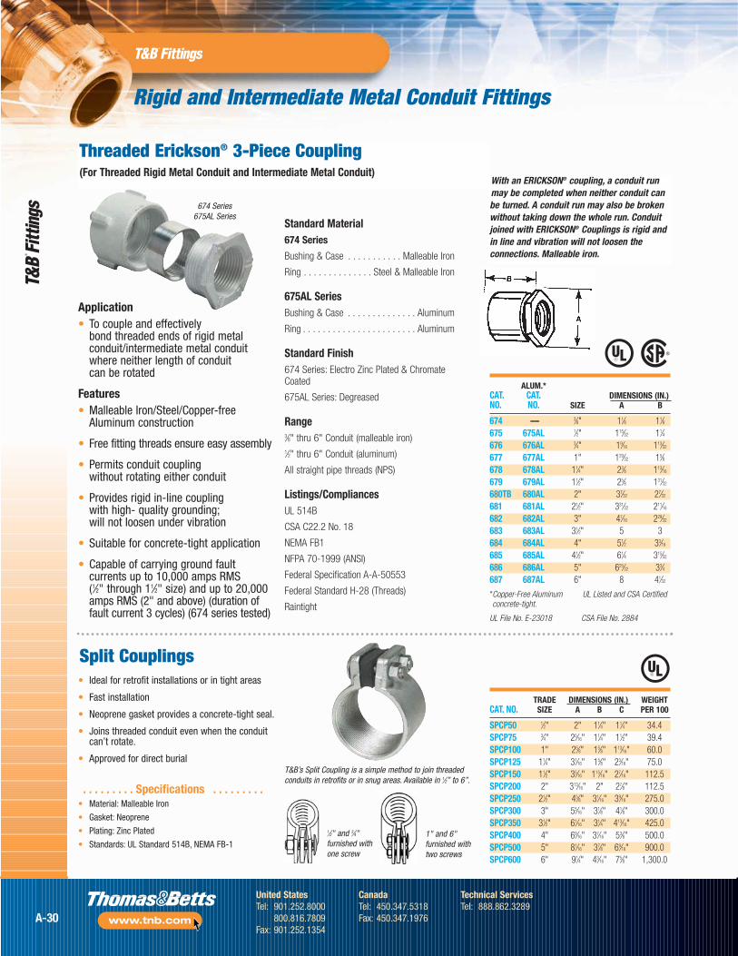
Application• To couple and effectively
bond threaded ends of rigid metalconduit/intermediate metal conduitwhere neither length of conduit can be rotated
Features• Malleable Iron/Steel/Copper-free
Aluminum construction
• Free fitting threads ensure easy assembly
• Permits conduit coupling without rotating either conduit
• Provides rigid in-line coupling with high- quality grounding; will not loosen under vibration
• Suitable for concrete-tight application
• Capable of carrying ground faultcurrents up to 10,000 amps RMS (1⁄2" through 11⁄2" size) and up to 20,000amps RMS (2" and above) (duration offault current 3 cycles) (674 series tested)
With an ERICKSON® coupling, a conduit runmay be completed when neither conduit canbe turned. A conduit run may also be brokenwithout taking down the whole run. Conduitjoined with ERICKSON® Couplings is rigid andin line and vibration will not loosen theconnections. Malleable iron.
ALUM.*CAT. CAT. DIMENSIONS (IN.)NO. NO. SIZE A B
674 — 3⁄8" 11⁄8 11⁄8675 675AL 1⁄2" 115⁄32 11⁄4676 676AL 3⁄4" 19⁄16 113⁄32
677 677AL 1" 129⁄32 15⁄8678 678AL 11⁄4" 23⁄8 113⁄16
679 679AL 11⁄2" 25⁄8 131⁄32
680TB 680AL 2" 37⁄32 27⁄32
681 681AL 21⁄2" 331⁄32 211⁄16
682 682AL 3" 47⁄16 229⁄32
683 683AL 31⁄2" 5 3684 684AL 4" 51⁄2 33⁄16
685 685AL 41⁄2" 61⁄4 315⁄32
686 686AL 5" 625⁄32 33⁄4687 687AL 6" 8 41⁄32
*Copper-Free Aluminum UL Listed and CSA Certifiedconcrete-tight.
UL File No. E-23018 CSA File No. 2884
Threaded Erickson® 3-Piece Coupling(For Threaded Rigid Metal Conduit and Intermediate Metal Conduit)
674 Series675AL Series
Standard Material674 Series
Bushing & Case . . . . . . . . . . . Malleable Iron
Ring . . . . . . . . . . . . . . Steel & Malleable Iron
675AL SeriesBushing & Case . . . . . . . . . . . . . . Aluminum
Ring . . . . . . . . . . . . . . . . . . . . . . . Aluminum
Standard Finish674 Series: Electro Zinc Plated & ChromateCoated
675AL Series: Degreased
Range3⁄8" thru 6" Conduit (malleable iron)1⁄2" thru 6" Conduit (aluminum)
All straight pipe threads (NPS)
Listings/CompliancesUL 514B
CSA C22.2 No. 18
NEMA FB1
NFPA 70-1999 (ANSI)
Federal Specification A-A-50553
Federal Standard H-28 (Threads)
Raintight
TRADE DIMENSIONS (IN.) WEIGHTCAT. NO. SIZE A B C PER 100
SPCP50 1⁄2" 2" 11⁄4" 11⁄4" 34.4SPCP75 3⁄4" 25⁄16" 11⁄4" 11⁄2" 39.4SPCP100 1" 25⁄8" 15⁄8" 113⁄16" 60.0SPCP125 11⁄4" 31⁄16" 15⁄8" 23⁄16" 75.0SPCP150 11⁄2" 35⁄16" 115⁄16" 27⁄16" 112.5SPCP200 2" 313⁄16" 2" 27⁄8" 112.5SPCP250 21⁄2" 45⁄8" 31⁄16" 39⁄16" 275.0SPCP300 3" 55⁄16" 31⁄8" 41⁄8" 300.0SPCP350 31⁄2" 61⁄16" 31⁄4" 413⁄16" 425.0SPCP400 4" 69⁄16" 37⁄16" 53⁄8" 500.0SPCP500 5" 81⁄16" 37⁄8" 69⁄16" 900.0SPCP600 6" 91⁄4" 43⁄16" 75⁄8" 1,300.0
• Ideal for retrofit installations or in tight areas
• Fast installation
• Neoprene gasket provides a concrete-tight seal.
• Joins threaded conduit even when the conduitcan’t rotate.
• Approved for direct burial
Split Couplings
1⁄2" and 3⁄4"furnished withone screw
1" and 6"furnished withtwo screws
. . . . . . . . . Specifications . . . . . . . . .• Material: Malleable Iron
• Gasket: Neoprene
• Plating: Zinc Plated
• Standards: UL Standard 514B, NEMA FB-1
T&B’s Split Coupling is a simple method to join threadedconduits in retrofits or in snug areas. Available in 1⁄2” to 6”.
A-30
United StatesTel: 901.252.8000
800.816.7809Fax: 901.252.1354
CanadaTel: 450.347.5318Fax: 450.347.1976
Technical ServicesTel: 888.862.3289
www.tnb.com
Rigid and Intermediate Metal Conduit Fittings
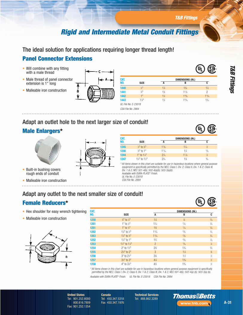
CAT. DIMENSIONS (IN.)NO. SIZE A B C
1250 3⁄4" to 1⁄2" 11⁄8 5⁄8 3⁄16
1261 1" to 1⁄2" 17⁄1621⁄32
3⁄16
1251 1" to 3⁄4" 13⁄8 11⁄163⁄16
1262 11⁄4" to 1⁄2" 113⁄1623⁄32
3⁄16
1263 11⁄4" to 3⁄4" 113⁄1623⁄32
3⁄16
1252 11⁄4" to 1" 13⁄4 25⁄327⁄32
1253 11⁄2" to 11⁄4" 2 13⁄161⁄4
1254 2" to 11⁄2" 23⁄8 13⁄169⁄32
1255 21⁄2" to 2" 3 11⁄4 3⁄81256 3" to 21⁄2" 35⁄8 11⁄2 1⁄21257 31⁄2" to 3" 41⁄8 19⁄16
1⁄21258 4" to 31⁄2" 45⁄8 19⁄16
1⁄2
* All items shown in this chart are suitable for use in hazardous locations where general purpose equipment is specificallypermitted by the NEC; Class I, Div. 2; Class II, Div. 1 & 2; Class III, Div. 1 & 2, NEC 501-4(b); 502-4(a) (b); 503-3(a) (b).
Available with DURA-PLATE® Finish. UL File No. E-23018 CSA File No. 2884
CAT. DIMENSIONS (IN.)NO. SIZE A B C
1245 1⁄2" to 3⁄4" 113⁄32 11⁄161⁄2
1246 3⁄4" to 1" 111⁄16 11⁄4 15⁄32
1244 1" to 11⁄4" 21⁄16 111⁄321⁄2
1247 11⁄4" to 11⁄2" 25⁄16 13⁄8 9⁄16
* All items shown in this chart are suitable for use in hazardous locations where general purposeequipment is specifically permitted by the NEC; Class I, Div. 2; Class II, Div. 1 & 2; Class III,Div. 1 & 2, NEC 501-4(b); 502-4(a)(b); 503-3(a)(b).Available with DURA-PLATE® Finish.UL File No. E-23018CSA File No. 2884
The ideal solution for applications requiring longer thread length!
Panel Connector Extensions
• Will combine with any fittingwith a male thread
• Male thread of panel connectorextension is 1" long
• Malleable iron construction
Adapt an outlet hole to the next larger size of conduit!
Male Enlargers*
• Built-in bushing covers rough ends of conduit
• Malleable iron construction
Adapt any outlet to the next smaller size of conduit!
Female Reducers*• Hex shoulder for easy wrench tightening
• Malleable iron construction
CAT. DIMENSIONS (IN.)NO. SIZE A B C
1440 1⁄2" 11⁄4 13⁄32 17⁄81441 3⁄4" 13⁄8 111⁄32 21442 1" 11⁄4 119⁄32 115⁄16
1443 11⁄4" 11⁄4 115⁄16 15⁄16
UL File No. E-23018
CSA File No. 2884
A-31
United StatesTel: 901.252.8000
800.816.7809Fax: 901.252.1354
CanadaTel: 450.347.5318Fax: 450.347.1976
Technical ServicesTel: 888.862.3289
www.tnb.com
Rigid and Intermediate Metal Conduit Fittings
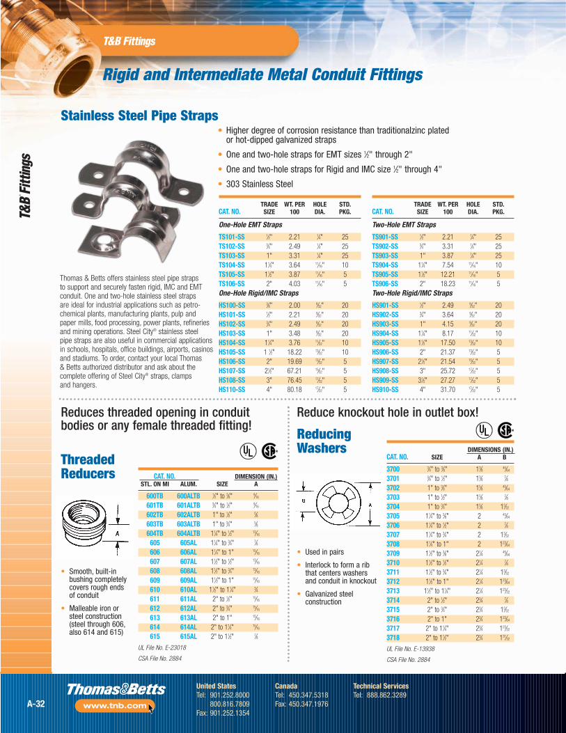
Reduces threaded opening in conduitbodies or any female threaded fitting!
Reduce knockout hole in outlet box!
ReducingWashers
• Used in pairs
• Interlock to form a ribthat centers washersand conduit in knockout
• Galvanized steelconstruction
CAT. NO. DIMENSION (IN.)STL. ON MI ALUM. SIZE A
600TB 600ALTB 1⁄2" to 3⁄8" 9⁄16
601TB 601ALTB 3⁄4" to 1⁄2" 9⁄16
602TB 602ALTB 1" to 1⁄2" 5⁄8603TB 603ALTB 1" to 3⁄4" 5⁄8604TB 604ALTB 11⁄4" to 1⁄2" 13⁄16
605 605AL 11⁄4" to 3⁄4" 7⁄8606 606AL 11⁄4" to 1" 15⁄16
607 607AL 11⁄2" to 1⁄2" 13⁄16
608 608AL 11⁄2" to 3⁄4" 13⁄16
609 609AL 11⁄2" to 1" 15⁄16
610 610AL 11⁄2" to 11⁄4" 3⁄4611 611AL 2" to 1⁄2" 15⁄16
612 612AL 2" to 3⁄4" 15⁄16
613 613AL 2" to 1" 15⁄16
614 614AL 2" to 11⁄4" 15⁄16
615 615AL 2" to 11⁄2" 7⁄8
UL File No. E-23018
CSA File No. 2884
®
®
®
®
• Smooth, built-inbushing completelycovers rough endsof conduit
• Malleable iron orsteel construction(steel through 606,also 614 and 615)
ThreadedReducers
TRADE WT. PER HOLE STD.CAT. NO. SIZE 100 DIA. PKG.
One-Hole EMT Straps
TS101-SS 1⁄2" 2.21 1⁄4" 25TS102-SS 3⁄4" 2.49 1⁄4" 25TS103-SS 1" 3.31 1⁄4" 25TS104-SS 11⁄4" 3.64 11⁄16" 10TS105-SS 11⁄2" 3.87 11⁄16" 5TS106-SS 2" 4.03 11⁄16" 5One-Hole Rigid/IMC Straps
HS100-SS 3⁄8" 2.00 9⁄32" 20HS101-SS 1⁄2" 2.21 9⁄32" 20HS102-SS 3⁄4" 2.49 9⁄32" 20HS103-SS 1" 3.48 9⁄32" 20HS104-SS 11⁄4" 3.76 11⁄32" 10HS105-SS 1 1⁄2" 18.22 13⁄32" 10HS106-SS 2" 19.69 13⁄32" 5HS107-SS 21⁄2" 67.21 15⁄32" 5HS108-SS 3" 76.45 17⁄32" 5HS110-SS 4" 80.18 17⁄32" 5
TRADE WT. PER HOLE STD.CAT. NO. SIZE 100 DIA. PKG.
Two-Hole EMT Straps
TS901-SS 1⁄2" 2.21 1⁄4" 25TS902-SS 3⁄4" 3.31 1⁄4" 25TS903-SS 1" 3.87 1⁄4" 25TS904-SS 11⁄4" 7.54 11⁄16" 10TS905-SS 11⁄2" 12.21 11⁄16" 5TS906-SS 2" 18.23 11⁄16" 5Two-Hole Rigid/IMC Straps
HS901-SS 1⁄2" 2.49 9⁄32" 20HS902-SS 3⁄4" 3.64 9⁄32" 20HS903-SS 1" 4.15 9⁄32" 20HS904-SS 11⁄4" 8.17 11⁄32" 10HS905-SS 11⁄2" 17.50 13⁄32" 10HS906-SS 2" 21.37 13⁄32" 5HS907-SS 21⁄2" 21.54 15⁄32" 5HS908-SS 3" 25.72 17⁄32" 5HS909-SS 31⁄2" 27.27 17⁄32" 5HS910-SS 4" 31.70 17⁄32" 5
Thomas & Betts offers stainless steel pipe straps to support and securely fasten rigid, IMC and EMTconduit. One and two-hole stainless steel straps are ideal for industrial applications such as petro-chemical plants, manufacturing plants, pulp and paper mills, food processing, power plants, refineriesand mining operations. Steel City® stainless steel pipe straps are also useful in commercial applicationsin schools, hospitals, office buildings, airports, casinosand stadiums. To order, contact your local Thomas & Betts authorized distributor and ask about thecomplete offering of Steel City® straps, clamps and hangers.
Stainless Steel Pipe Straps• Higher degree of corrosion resistance than traditionalzinc plated
or hot-dipped galvanized straps
• One and two-hole straps for EMT sizes 1⁄2" through 2"
• One and two-hole straps for Rigid and IMC size 1⁄2" through 4"
• 303 Stainless Steel
DIMENSIONS (IN.)CAT. NO. SIZE A B
3700 3⁄4" to 3⁄8" 13⁄8 45⁄64
3701 3⁄4" to 1⁄2" 13⁄8 7⁄83702 1" to 3⁄8" 15⁄8 45⁄64
3703 1" to 1⁄2" 15⁄8 7⁄83704 1" to 3⁄4" 15⁄8 13⁄32
3705 11⁄4" to 3⁄8" 2 45⁄64
3706 11⁄4" to 1⁄2" 2 7⁄83707 11⁄4" to 3⁄4" 2 13⁄32
3708 11⁄4" to 1" 2 123⁄64
3709 11⁄2" to 3⁄8" 21⁄4 45⁄64
3710 11⁄2" to 1⁄2" 21⁄4 7⁄83711 11⁄2" to 3⁄4" 21⁄4 13⁄32
3712 11⁄2" to 1" 21⁄4 123⁄64
3713 11⁄2" to 11⁄4" 21⁄4 123⁄32
3714 2" to 1⁄2" 23⁄4 7⁄83715 2" to 3⁄4" 23⁄4 13⁄32
3716 2" to 1" 23⁄4 123⁄64
3717 2" to 11⁄4" 23⁄4 123⁄32
3718 2" to 11⁄2" 23⁄4 131⁄32
UL File No. E-13938
CSA File No. 2884
A-32
United StatesTel: 901.252.8000
800.816.7809Fax: 901.252.1354
CanadaTel: 450.347.5318Fax: 450.347.1976
Technical ServicesTel: 888.862.3289
www.tnb.com
Rigid and Intermediate Metal Conduit Fittings
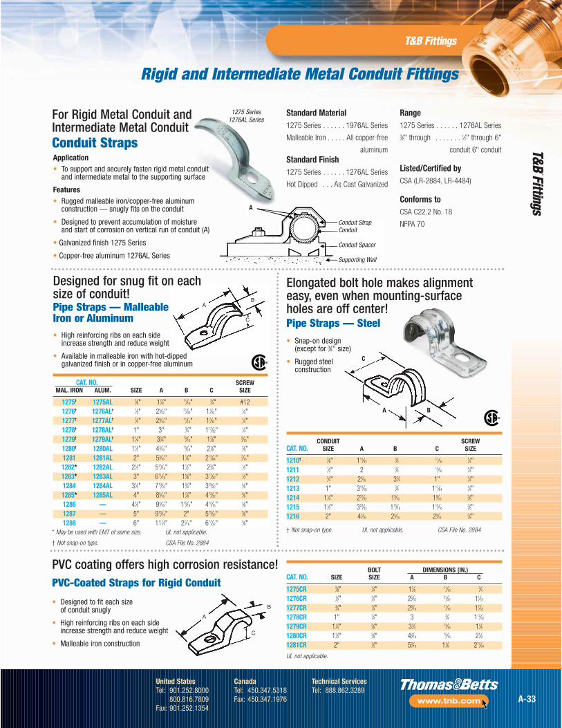
Conduit Straps
A
C
B
CONDUIT SCREWCAT. NO. SIZE A B C SIZE
1210† 3⁄8" 115⁄323⁄4 11⁄16
1⁄4"1211 1⁄2" 2 3⁄4 15⁄16
1⁄4"1212 3⁄4" 25⁄16 33⁄4 1" 1⁄4"1213 1" 313⁄16
3⁄4 117⁄641⁄4"
1214 11⁄4" 231⁄32 19⁄16 19⁄163⁄8"
1215 11⁄2" 323⁄32 113⁄16 113⁄163⁄8"
1216 2" 47⁄16 25⁄16 25⁄163⁄8"
A B
C
®
Pipe Straps — MalleableIron or Aluminum
Designed for snug fit on each size of conduit!
CAT. NO. SCREWMAL. IRON ALUM. SIZE A B C SIZE
1275† 1275AL 3⁄8" 17⁄8" 11⁄16" 3⁄4" #121276† 1276AL† 1⁄2" 25⁄32" 21⁄32" 11⁄32" 1⁄4"1277† 1277AL† 3⁄4" 29⁄16" 11⁄16" 17⁄32" 1⁄4"1278† 1278AL† 1" 3" 3⁄4" 117⁄32" 1⁄4"1279† 1279AL† 11⁄4" 33⁄4" 13⁄16" 17⁄8" 5⁄16"1280† 1280AL 11⁄2" 43⁄16" 15⁄16" 21⁄8" 3⁄8"1281 1281AL 2" 53⁄16" 11⁄8" 217⁄64" 7⁄16"1282* 1282AL 21⁄2" 515⁄16" 11⁄2" 23⁄4" 1⁄2"1283* 1283AL 3" 611⁄16" 15⁄8" 311⁄32" 1⁄2"1284 1284AL 31⁄2" 719⁄32" 13⁄4" 329⁄32" 5⁄8"1285* 1285AL 4" 85⁄16" 17⁄8" 413⁄32" 5⁄8"1286 — 41⁄2" 93⁄16" 115⁄16" 415⁄16" 5⁄8"1287 — 5" 915⁄16" 2" 515⁄32" 5⁄8"1288 — 6" 111⁄2" 27⁄16" 617⁄32" 5⁄8"
• High reinforcing ribs on each side increase strength and reduce weight
• Available in malleable iron with hot-dipped galvanized finish or in copper-free aluminum
* May be used with EMT of same size.
† Not snap-on type.
UL not applicable.
CSA File No. 2884
®
† Not snap-on type. UL not applicable. CSA File No. 2884
Pipe Straps — Steel
BOLT DIMENSIONS (IN.)CAT. NO. SIZE SIZE A B C
1275CR 3⁄8" 1⁄4" 17⁄8 11⁄163⁄4
1276CR 1⁄2" 1⁄4" 25⁄3221⁄32 11⁄32
1277CR 3⁄4" 1⁄4" 29⁄1611⁄16 17⁄32
1278CR 1" 1⁄4" 3 3⁄4 117⁄32
1279CR 11⁄4" 3⁄8" 33⁄4 13⁄16 17⁄81280CR 11⁄2" 3⁄8" 43⁄16
15⁄16 21⁄81281CR 2" 1⁄2" 53⁄16 11⁄8 217⁄64
UL not applicable.
A
B
C
PVC coating offers high corrosion resistance!
• Snap-on design (except for 3⁄8" size)
• Rugged steelconstruction
Elongated bolt hole makes alignmenteasy, even when mounting-surfaceholes are off center!
• Designed to fit each size of conduit snugly
• High reinforcing ribs on each sideincrease strength and reduce weight
• Malleable iron construction
Application• To support and securely fasten rigid metal conduit
and intermediate metal to the supporting surface
Features• Rugged malleable iron/copper-free aluminum
construction — snugly fits on the conduit
• Designed to prevent accumulation of moisture and start of corrosion on vertical run of conduit (A)
• Galvanized finish 1275 Series
• Copper-free aluminum 1276AL Series
For Rigid Metal Conduit andIntermediate Metal Conduit
PVC-Coated Straps for Rigid Conduit
Conduit StrapConduit
Conduit Spacer
Supporting Wall
A
Standard Material1275 Series . . . . . . 1976AL Series
Malleable Iron . . . . . All copper-free
aluminumStandard Finish1275 Series . . . . . . 1276AL Series
Hot Dipped . . . As Cast Galvanized
Range1275 Series . . . . . . 1276AL Series3⁄8" through . . . . . . . 1⁄2" through 6"
conduit 6" conduit
Listed/Certified byCSA (LR-2884, LR-4484)
Conforms toCSA C22.2 No. 18
NFPA 70
1275 Series1276AL Series
A-33
United StatesTel: 901.252.8000
800.816.7809Fax: 901.252.1354
CanadaTel: 450.347.5318Fax: 450.347.1976
Technical ServicesTel: 888.862.3289
www.tnb.com
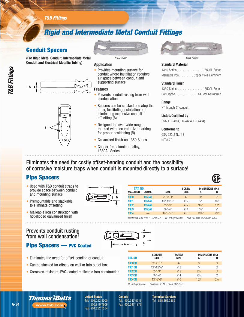
Rigid and Intermediate Metal Conduit Fittings
CONDUIT SCREW DIMENSIONS (IN.)CAT. NO. SIZE SIZE A B
1350CR 1⁄2"-3⁄4"-1" #7 3 7⁄81351CR 11⁄4"-11⁄2"-2" #12 5 3⁄81352CR 21⁄2"-3" #12 69⁄16
3⁄41353CR 31⁄2"-4" #14 79⁄16 21354CR 41⁄2"-5"-6" #16 109⁄16 29⁄16
UL not applicable. Conforms to NEC SECT. 300-5-c.
• Eliminates the need for offset-bending of conduit
• Can be stacked for offsets on wall or into outlet box
• Corrosion-resistant, PVC-coated malleable iron construction
Application• Provides mounting surface for
conduit where installation requiresair space between conduit andsupporting surface
Features• Prevents conduit rusting from wall
condensation
• Spacers can be stacked one atop theother, facilitating installation andeliminating expensive conduitoffsetting (A)
• Designed to cover wide range;marked with accurate size markingfor proper positioning (B)
• Galvanized finish on 1350 Series
• Copper-free aluminum alloy,1350AL Series
Standard Material1350 Series. . . . . . . . . . . . . . . . 1350AL Series
Malleable Iron . . . . . . . . . Copper-free aluminum
Standard Finish1350 Series. . . . . . . . . . . . . . . . 1350AL Series
Hot Dipped . . . . . . . . . . . . . As Cast Galvanized
Range1⁄2" through 6" conduit
Listed/Certified byCSA (LR-2884, LR-4484, LR-4484)
Conforms toCSA C22.2 No. 18
NFPA 70
Prevents conduit rusting from wall condensation!
Pipe Spacers — PVC Coated
Eliminates the need for costly offset-bending conduit and the possibility of corrosive moisture traps when conduit is mounted directly to a surface!
Pipe Spacers• Used with T&B conduit straps to
provide space between conduitand mounting surface
• Premountable and stackable to eliminate offsetting
• Malleable iron construction withhot-dipped galvanized finish
CAT. NO. SCREW DIMENSIONS (IN.)MAL. IRON ALUM. SIZE SIZE A B
1350 1350AL 1⁄2", 3⁄4", 1" #7 3" 7⁄8"1351 1351AL 11⁄4"-11⁄2"-2" #12 5" 13⁄16"1352 1352AL 21⁄2"-3" #12 99⁄16" 13⁄4"1353 1353AL 31⁄2"-4" #14 79⁄16" 2"1354 — 41⁄2"-5"-6" #16 109⁄16" 29⁄16"
Conforms to NEC SECT. 300-5-c. UL not applicable. CSA File Nos. 2884 and 4484.
A
B
1351 Series1350 Series
Conduit Spacers(For Rigid Metal Conduit, Intermediate MetalConduit and Electrical Metallic Tubing)
A-34
United StatesTel: 901.252.8000
800.816.7809Fax: 901.252.1354
CanadaTel: 450.347.5318Fax: 450.347.1976
Technical ServicesTel: 888.862.3289
www.tnb.com
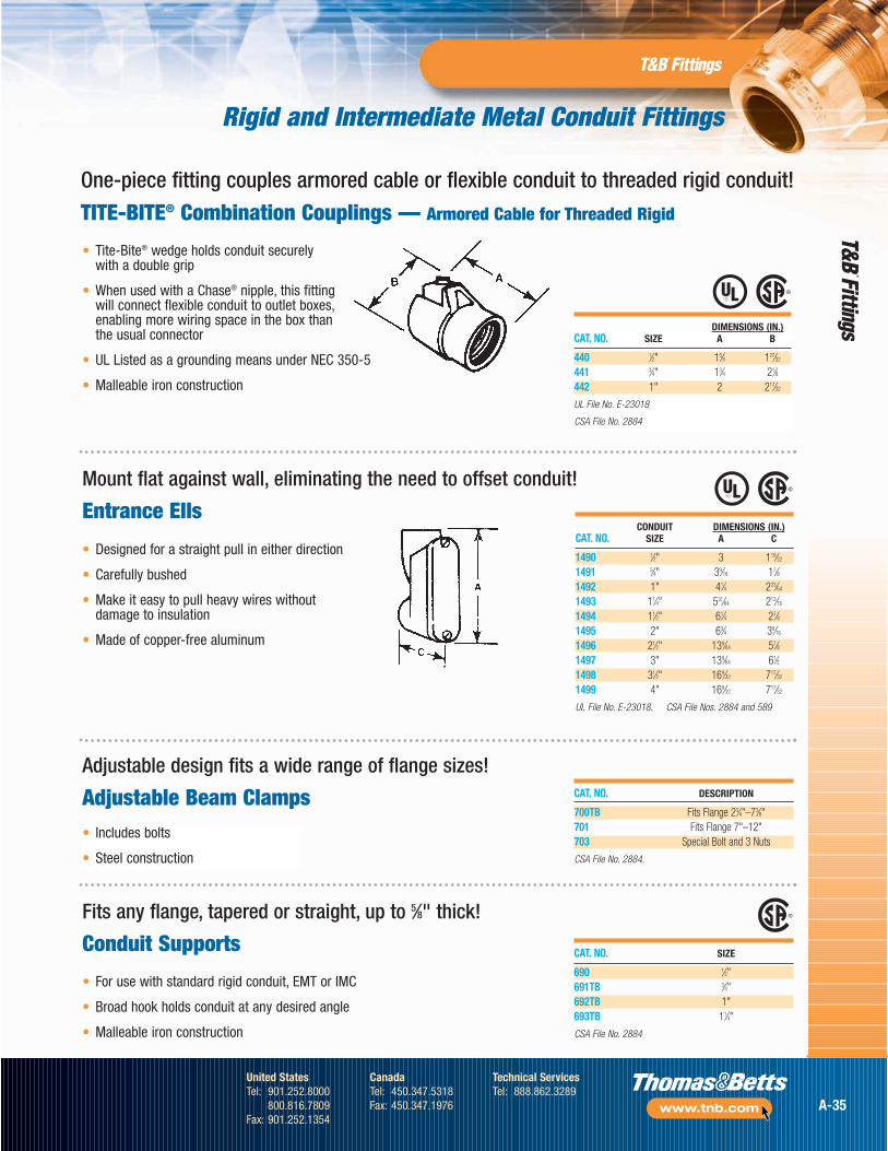
Rigid and Intermediate Metal Conduit Fittings
CAT. NO. SIZE
690 1⁄2"691TB 3⁄4"692TB 1"693TB 11⁄4"
CSA File No. 2884
• Includes bolts
• Steel construction
DIMENSIONS (IN.)CAT. NO. SIZE A B
440 1⁄2" 15⁄8 127⁄32
441 3⁄4" 13⁄4 21⁄8442 1" 2 217⁄32
UL File No. E-23018
CSA File No. 2884
CONDUIT DIMENSIONS (IN.)CAT. NO. SIZE A C
1490 1⁄2" 3 119⁄32
1491 3⁄4" 39⁄16 17⁄81492 1" 41⁄4 223⁄64
1493 11⁄4" 531⁄64 213⁄16
1494 11⁄2" 61⁄4 27⁄81495 2" 63⁄4 39⁄16
1496 21⁄2" 139⁄64 57⁄81497 3" 139⁄64 61⁄21498 31⁄2" 169⁄32 717⁄32
1499 4" 169⁄32 717⁄32
UL File No. E-23018. CSA File Nos. 2884 and 589
One-piece fitting couples armored cable or flexible conduit to threaded rigid conduit!
TITE-BITE® Combination Couplings — Armored Cable for Threaded Rigid
• Tite-Bite® wedge holds conduit securely with a double grip
• When used with a Chase® nipple, this fitting will connect flexible conduit to outlet boxes,enabling more wiring space in the box than the usual connector
• UL Listed as a grounding means under NEC 350-5
• Malleable iron construction
Mount flat against wall, eliminating the need to offset conduit!
Entrance Ells
Adjustable design fits a wide range of flange sizes!
Adjustable Beam Clamps CAT. NO. DESCRIPTION
700TB Fits Flange 23⁄4"–73⁄8"701 Fits Flange 7"–12"703 Special Bolt and 3 Nuts
CSA File No. 2884.
Fits any flange, tapered or straight, up to 5⁄8" thick!
Conduit Supports
• Designed for a straight pull in either direction
• Carefully bushed
• Make it easy to pull heavy wires without damage to insulation
• Made of copper-free aluminum
• For use with standard rigid conduit, EMT or IMC
• Broad hook holds conduit at any desired angle
• Malleable iron construction
A-35
United StatesTel: 901.252.8000
800.816.7809Fax: 901.252.1354
CanadaTel: 450.347.5318Fax: 450.347.1976
Technical ServicesTel: 888.862.3289
www.tnb.com