Embed Size (px)
Citation preview
Installation Instructions
Original Instructions
RightSight M30Catalog Numbers 42AF-P2MAB1-F4,42AF-P2MAB1-D4, 42AF-P2RHB1-G4, 42AF-E1EZB1-F4, 42AF-E1EZB1-D4, 42AF-R1MAB1-D4, 42AF-R1MAB1-F4, 42AF-R1RHB1-G4, 42AF-E1UZB1-G4, 42AF-P2CHB1-A2, 42AF-R1CHB1-A2, 42AF-E1UZB1-A2, 42AF-P2SHB1-G4, 42AF-R1SHB1-G4, 42AF-P2CHB1-M5, 42AF-R1CHB1-M5, 42AF-E1UZB1-M4
DescriptionThe RightSight™ M30 family of photoelectric sensors offers high-performance general-purpose sensing in a robust flexible package. They are designed for applications where simplified installation and maintenance are required.
Designed to withstand the rigors of material handling and packaging environments, the RightSight M30 standard models can withstand IP69K high-pressure washdowns.
Features• Right-angle housing with universal 30 mm (1.18 in.) threaded
nose and 18 mm (0.71 in.) threaded base for maximum application flexibility
• 360° highly visible (status indicators helps the operators verify proper operation regardless of sensor installation location)
• Visible status indicator light source for ease of alignment• Alignment aid helps deliver reliable operating margin• Dual auto PNP or NPN outputs for added application
flexibility• IP67 and IP69K rated enclosure• IO-Link 1.1 Communication protocol that is offered in all
standard modes
Status Indicators
Table 1 provides indicator status in the RUN mode, during operation. The sensor is always in run mode except when being taught.
See https://ab.rockwellautomation.com/Sensors-Switches/Photoelectric-Sensors for additional details about the operation of the RightSight M30 in IO-Link mode.
IMPORTANT Save these instructions for future use.
Topic Page
Description 1
Features 1
Status Indicators 1
Specifications 2
Sensor User Interface 2
Wiring 2
Dimensions 3
Typical Response Curves 4
Accessories 4
Summary of Changes 6Table 1 - Standard I/O (Auto PNP/NPN) Operating Mode Indication
Color Status Description
Green
OFF Power is off
ON Power is on
Flash (6 Hz) Unstable light: 0.8 X <margin<1.5X
Flash (1.4 Hz) Output short circuit protection active
OrangeOFF Output de-energized
ON Output energized
Table 2 - I/O Link Operating Mode Indication
Color Status Description
GreenOFF Power is off
Flash (1 Hz) Power is on
OrangeOFF Output de-energized
ON Output energized
Orange LEDGreen LED
RightSight M30
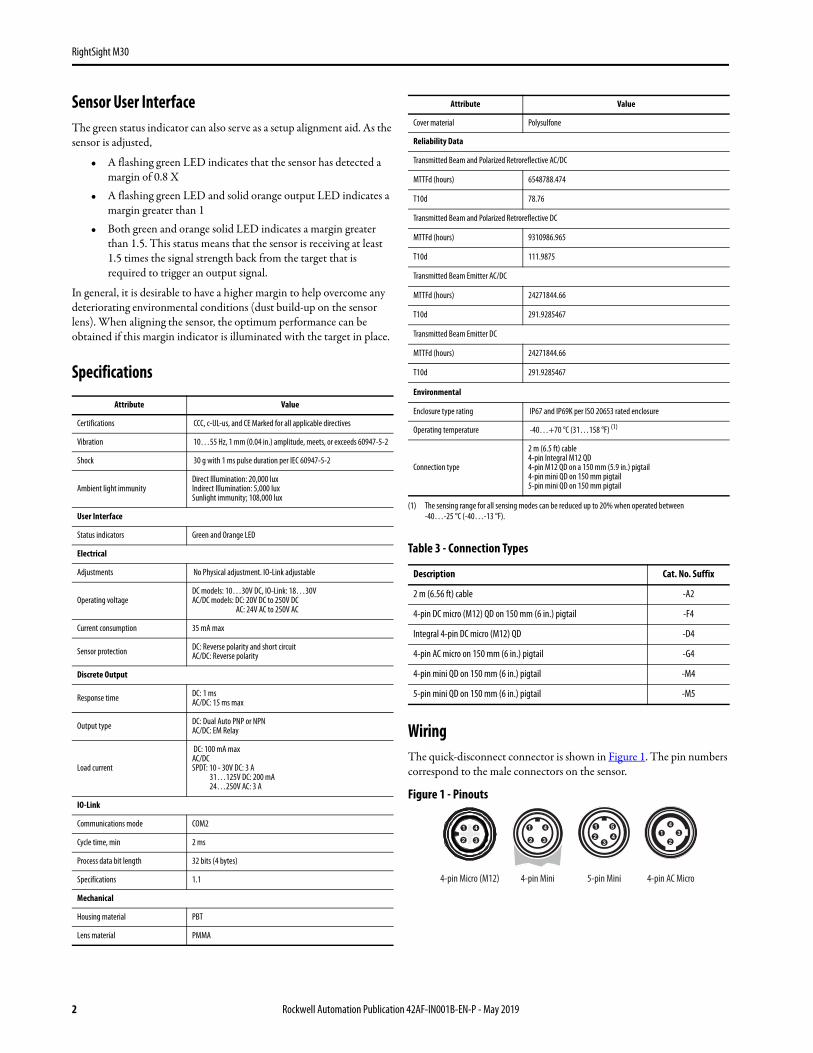
Sensor User InterfaceThe green status indicator can also serve as a setup alignment aid. As the sensor is adjusted,
• A flashing green LED indicates that the sensor has detected a margin of 0.8 X
• A flashing green LED and solid orange output LED indicates a margin greater than 1
• Both green and orange solid LED indicates a margin greater than 1.5. This status means that the sensor is receiving at least 1.5 times the signal strength back from the target that is required to trigger an output signal.
In general, it is desirable to have a higher margin to help overcome any deteriorating environmental conditions (dust build-up on the sensor lens). When aligning the sensor, the optimum performance can be obtained if this margin indicator is illuminated with the target in place.
Specifications
WiringThe quick-disconnect connector is shown in Figure 1. The pin numbers correspond to the male connectors on the sensor.
Figure 1 - Pinouts
Attribute Value
Certifications CCC, c-UL-us, and CE Marked for all applicable directives
Vibration 10…55 Hz, 1 mm (0.04 in.) amplitude, meets, or exceeds 60947-5-2
Shock 30 g with 1 ms pulse duration per IEC 60947-5-2
Ambient light immunityDirect Illumination: 20,000 luxIndirect Illumination: 5,000 luxSunlight immunity; 108,000 lux
User Interface
Status indicators Green and Orange LED
Electrical
Adjustments No Physical adjustment. IO-Link adjustable
Operating voltageDC models: 10…30V DC, IO-Link: 18…30VAC/DC models: DC: 20V DC to 250V DC AC: 24V AC to 250V AC
Current consumption 35 mA max
Sensor protection DC: Reverse polarity and short circuitAC/DC: Reverse polarity
Discrete Output
Response time DC: 1 msAC/DC: 15 ms max
Output type DC: Dual Auto PNP or NPNAC/DC: EM Relay
Load current
DC: 100 mA maxAC/DCSPDT: 10 - 30V DC: 3 A 31…125V DC: 200 mA 24…250V AC: 3 A
IO-Link
Communications mode COM2
Cycle time, min 2 ms
Process data bit length 32 bits (4 bytes)
Specifications 1.1
Mechanical
Housing material PBT
Lens material PMMA
Cover material Polysulfone
Reliability Data
Transmitted Beam and Polarized Retroreflective AC/DC
MTTFd (hours) 6548788.474
T10d 78.76
Transmitted Beam and Polarized Retroreflective DC
MTTFd (hours) 9310986.965
T10d 111.9875
Transmitted Beam Emitter AC/DC
MTTFd (hours) 24271844.66
T10d 291.9285467
Transmitted Beam Emitter DC
MTTFd (hours) 24271844.66
T10d 291.9285467
Environmental
Enclosure type rating IP67 and IP69K per ISO 20653 rated enclosure
Operating temperature -40…+70 °C (31…158 °F) (1)
Connection type
2 m (6.5 ft) cable4-pin Integral M12 QD4-pin M12 QD on a 150 mm (5.9 in.) pigtail4-pin mini QD on 150 mm pigtail5-pin mini QD on 150 mm pigtail
(1) The sensing range for all sensing modes can be reduced up to 20% when operated between -40…-25 °C (-40…-13 °F).
Table 3 - Connection Types
Description Cat. No. Suffix
2 m (6.56 ft) cable -A2
4-pin DC micro (M12) QD on 150 mm (6 in.) pigtail -F4
Integral 4-pin DC micro (M12) QD -D4
4-pin AC micro on 150 mm (6 in.) pigtail -G4
4-pin mini QD on 150 mm (6 in.) pigtail -M4
5-pin mini QD on 150 mm (6 in.) pigtail -M5
Attribute Value
5-pin Mini4-pin Micro (M12) 4-pin Mini 4-pin AC Micro
2 Rockwell Automation Publication 42AF-IN001B-EN-P - May 2019
RightSight M30
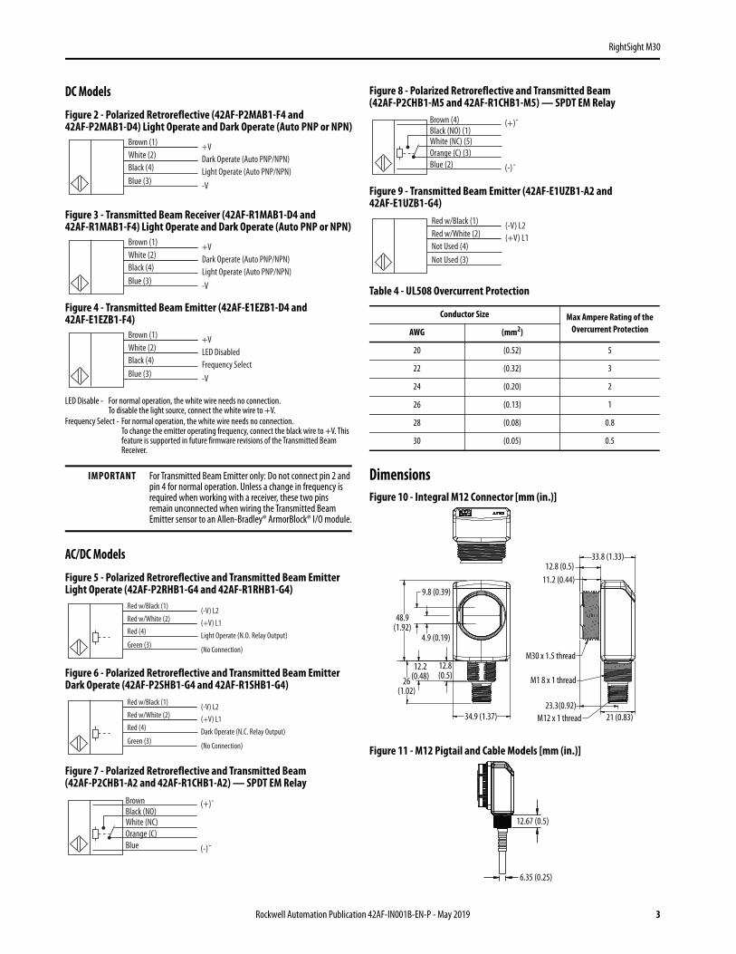
DC Models
Figure 2 - Polarized Retroreflective (42AF-P2MAB1-F4 and 42AF-P2MAB1-D4) Light Operate and Dark Operate (Auto PNP or NPN)
Figure 3 - Transmitted Beam Receiver (42AF-R1MAB1-D4 and 42AF-R1MAB1-F4) Light Operate and Dark Operate (Auto PNP or NPN)
Figure 4 - Transmitted Beam Emitter (42AF-E1EZB1-D4 and 42AF-E1EZB1-F4)
LED Disable - For normal operation, the white wire needs no connection.To disable the light source, connect the white wire to +V.
Frequency Select - For normal operation, the white wire needs no connection.To change the emitter operating frequency, connect the black wire to +V. This feature is supported in future firmware revisions of the Transmitted Beam Receiver.
AC/DC Models
Figure 5 - Polarized Retroreflective and Transmitted Beam Emitter Light Operate (42AF-P2RHB1-G4 and 42AF-R1RHB1-G4)
Figure 6 - Polarized Retroreflective and Transmitted Beam Emitter Dark Operate (42AF-P2SHB1-G4 and 42AF-R1SHB1-G4)
Figure 7 - Polarized Retroreflective and Transmitted Beam(42AF-P2CHB1-A2 and 42AF-R1CHB1-A2) — SPDT EM Relay
Figure 8 - Polarized Retroreflective and Transmitted Beam(42AF-P2CHB1-M5 and 42AF-R1CHB1-M5) — SPDT EM Relay
Figure 9 - Transmitted Beam Emitter (42AF-E1UZB1-A2 and 42AF-E1UZB1-G4)
DimensionsFigure 10 - Integral M12 Connector [mm (in.)]
Figure 11 - M12 Pigtail and Cable Models [mm (in.)]
IMPORTANT For Transmitted Beam Emitter only: Do not connect pin 2 and pin 4 for normal operation. Unless a change in frequency is required when working with a receiver, these two pins remain unconnected when wiring the Transmitted Beam Emitter sensor to an Allen-Bradley® ArmorBlock® I/O module.
Brown (1)
Blue (3)Black (4)White (2)
+V
-VLight Operate (Auto PNP/NPN)Dark Operate (Auto PNP/NPN)
Brown (1)
Blue (3)Black (4)White (2)
+V
-VLight Operate (Auto PNP/NPN)Dark Operate (Auto PNP/NPN)
Brown (1)
Blue (3)Black (4)White (2)
+V
-VFrequency SelectLED Disabled
Red w/Black (1)
Green (3)
Red (4)
Red w/White (2)(-V) L2
(No Connection)
Light Operate (N.O. Relay Output)
(+V) L1
Red w/Black (1)
Green (3)
Red (4)
Red w/White (2)(-V) L2
(No Connection)
Dark Operate (N.C. Relay Output)
(+V) L1
Brown
Orange (C)White (NC)Black (NO)
(+) ̃
(-) ̃Blue
Table 4 - UL508 Overcurrent Protection
Conductor Size Max Ampere Rating of the Overcurrent ProtectionAWG (mm2)
20 (0.52) 5
22 (0.32) 3
24 (0.20) 2
26 (0.13) 1
28 (0.08) 0.8
30 (0.05) 0.5
Brown (4)
Orange (C) (3)White (NC) (5)Black (NO) (1)
(+) ̃
(-) ̃Blue (2)
Red w/Black (1)
Not Used (3)Not Used (4)Red w/White (2)
(-V) L2(+V) L1
33.8 (1.33)12.8 (0.5)
21 (0.83)M12 x 1 thread23.3(0.92)
M1 8 x 1 thread
34.9 (1.37)
12.2(0.48)26
(1.02)
M30 x 1.5 thread
48.9(1.92)
9.8 (0.39)
12.8(0.5)
4.9 (0.19)
11.2 (0.44)
12.67 (0.5)
6.35 (0.25)
Rockwell Automation Publication 42AF-IN001B-EN-P - May 2019 3
RightSight M30
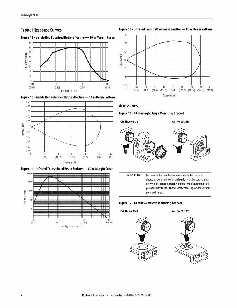
Typical Response CurvesFigure 12 - Visible Red Polarized Retroreflective — 10 m Margin Curve
Figure 13 - Visible Red Polarized Retroreflective — 10 m Beam Pattern
Figure 14 - Infrared Transmitted Beam Emitter — 80 m Margin Curve
Figure 15 - Infrared Transmitted Beam Emitter — 80 m Beam Pattern
AccessoriesFigure 16 - 30 mm Right Angle Mounting Bracket
Figure 17 - 18 mm Swivel/tilt Mounting Bracket
Oper
ating
Mar
gin
Distance [m (ft)]
0.01(0.03)
0.1(0.33)
1(3.28)
10(32.81)
0
10
50
60
20
40
70
30
80
Distance [m (ft)]
Dista
nce [
m]
0.250.20
0.15
0.10
0.05
0
-0.05
-0.10
-0.15
-0.20-0.25
0 4(13.12)
6(19.68)
8(26.25)
10(32.81)
12(39.37)
2(6.56)
100000
10000
1
10
100
1000
0.1(0.33)
1(3.28)
10(32.81)
100(328.08)
Sensing Distance [m (ft)]
Oper
ating
Mar
gin
Cat. No. 60-2421 Cat. No. 60-2439
IMPORTANT For polarized retroreflective sensors only: For optimal detection performance, when highly reflective targets pass between the emitter and the reflector, we recommend that you always install the rubber washer that is provided with the polarized sensor.
Cat. No. 60-2649 Cat. No. 60-2681
-1.5
-1.0
-0.5
0
0.5
1.0
1.5
0 10(32.8)
20(65.6)
30(98.4)
40(131.2)
50(164)
60(196.8)
70(229.6)
80(262.5)
90(295.3)
Dista
nce (
m)
Distance [m (ft)]
4 Rockwell Automation Publication 42AF-IN001B-EN-P - May 2019
RightSight M30
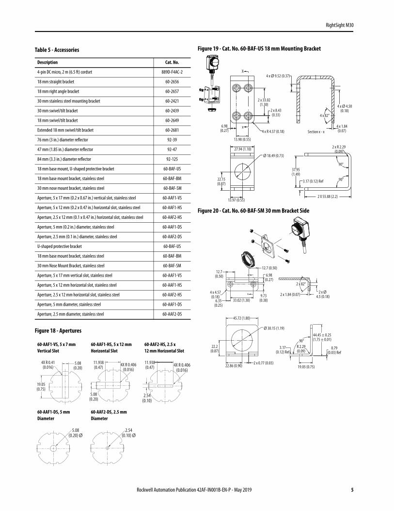
Figure 18 - Apertures
Figure 19 - Cat. No. 60-BAF-US 18 mm Mounting Bracket
Figure 20 - Cat. No. 60-BAF-SM 30 mm Bracket Side
Table 5 - Accessories
Description Cat. No.
4-pin DC micro, 2 m (6.5 ft) cordset 889D-F4AC-2
18 mm straight bracket 60-2656
18 mm right angle bracket 60-2657
30 mm stainless steel mounting bracket 60-2421
30 mm swivel/tilt bracket 60-2439
18 mm swivel/tilt bracket 60-2649
Extended 18 mm swivel/tilt bracket 60-2681
76 mm (3 in.) diameter reflector 92-39
47 mm (1.85 in.) diameter reflector 92-47
84 mm (3.3 in.) diameter reflector 92-125
18 mm base mount, U-shaped protective bracket 60-BAF-US
18 mm base mount bracket, stainless steel 60-BAF-BM
30 mm nose mount bracket, stainless steel 60-BAF-SM
Aperture, 5 x 17 mm (0.2 x 0.67 in.) vertical slot, stainless steel 60-AAF1-VS
Aperture, 5 x 12 mm (0.2 x 0.47 in.) horizontal slot, stainless steel 60-AAF1-HS
Aperture, 2.5 x 12 mm (0.1 x 0.47 in.) horizontal slot, stainless steel 60-AAF2-HS
Aperture, 5 mm (0.2 in.) diameter, stainless steel 60-AAF1-DS
Aperture, 2.5 mm (0.1 in.) diameter, stainless steel 60-AAF2-DS
U-shaped protective bracket 60-BAF-US
18 mm base mount bracket, stainless steel 60-BAF-BM
30 mm Nose Mount Bracket, stainless steel 60-BAF-SM
Aperture, 5 x 17 mm vertical slot, stainless steel 60-AAF1-VS
Aperture, 5 x 12 mm horizontal slot, stainless steel 60-AAF1-HS
Aperture, 2.5 x 12 mm horizontal slot, stainless steel 60-AAF2-HS
Aperture, 5 mm diameter, stainless steel 60-AAF1-DS
Aperture, 2.5 mm diameter, stainless steel 60-AAF2-DS
60-AAF1-VS, 5 x 7 mm Vertical Slot
60-AAF1-HS, 5 x 12 mm Horizontal Slot
60-AAF2-HS, 2.5 x 12 mm Horizontal Slot
60-AAF1-DS, 5 mm Diameter
60-AAF2-DS, 2.5 mm Diameter
4X R 0.41(0.016)
5.08(0.20)
19.05(0.75)
4X R 0.406(0.016)
5.08(0.20)
11.938(0.47) 4X R 0.406
(0.016)
2.54(0.10)
11.938(0.47)
5.08(0.20) Ø
2.54(0.10) Ø
6.98(0.27)
13.98 (0.55)
4 x R 4.57 (0.18)
X
Section x - x
4 x Ø 4.50(0.18)
4 x 1.84(0.07)
4 x 82°
2 X 55.88 (2.2)
90°
3.17 (0.12) Ref
37.95(1.49)
13.97 (0.55)
22.15(0.87)
Ø 18.49 (0.73)27.94 (1.10)
4 x Ø 9.52 (0.37)
2 x 8.43(0.33)
2 x 33.02(1.30)
x
2 x R 2.29(0.09)
90°
12.7 (0.50)
33.02 (1.30)
6.98(0.27)
2 x 1.84 (0.07)9.73(0.38)
2 x Ø 4.5 (0.18)
12.7(0.50)
4 x 4.57(0.18)
6.35(0.25)
22.2(0.87)
22.86 (0.90)
Ø 30.15 (1.19)
3.17(0.12) Ref
19.05 (0.75)
44.45 ± 0.25(1.75 ± 0.01)
0.79(0.03) Ref
90°
2 x 82°
R 2.29(0.09)
2 x 0.77 (0.03)
45.72 (1.80)
Rockwell Automation Publication 42AF-IN001B-EN-P - May 2019 5
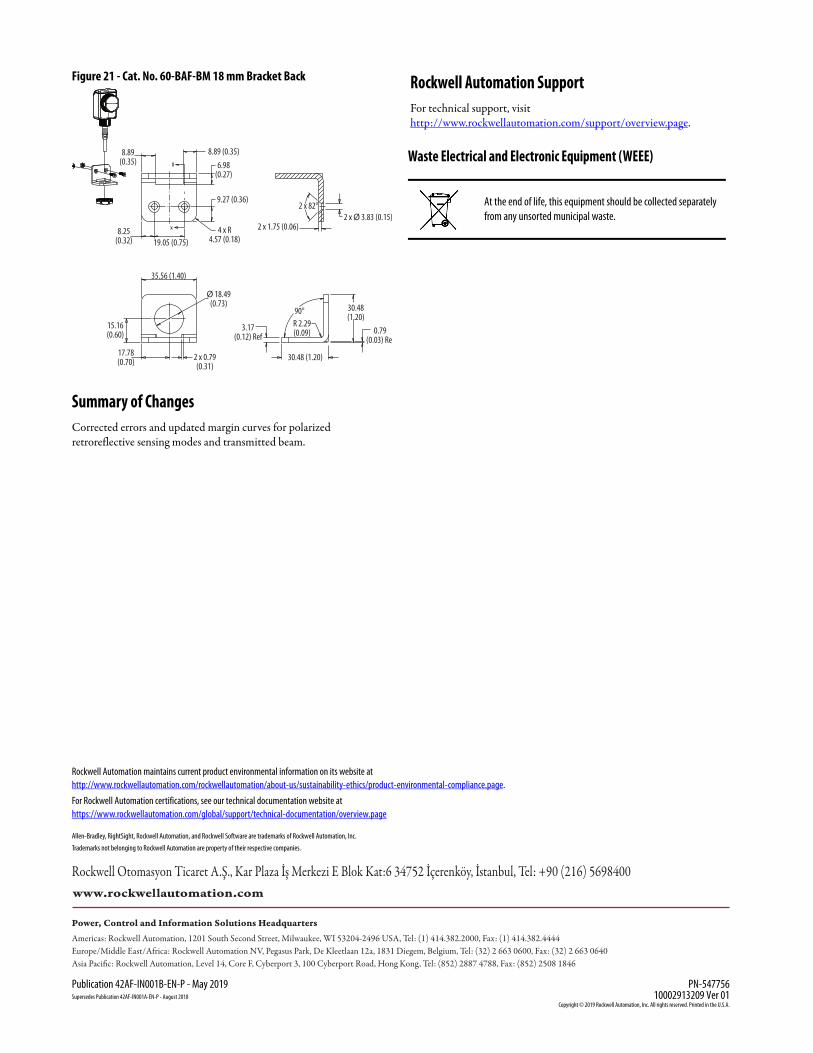
Figure 21 - Cat. No. 60-BAF-BM 18 mm Bracket Back
Summary of ChangesCorrected errors and updated margin curves for polarized retroreflective sensing modes and transmitted beam.
Rockwell Automation SupportFor technical support, visit http://www.rockwellautomation.com/support/overview.page.
Waste Electrical and Electronic Equipment (WEEE)
2 x Ø 3.83 (0.15)2 x 1.75 (0.06)
17.78(0.70) 30.48 (1.20)
3.17(0.12) Ref
2 x 0.79(0.31)
15.16(0.60)
90°
2 x 82°
R 2.29(0.09)
Ø 18.49(0.73)
8.89 (0.35)
9.27 (0.36)
6.98(0.27)
8.25(0.32)
8.89(0.35)
19.05 (0.75)4 x R
4.57 (0.18)
35.56 (1.40)
30.48(1.20)
0.79(0.03) Ref
At the end of life, this equipment should be collected separately from any unsorted municipal waste.
Allen-Bradley, RightSight, Rockwell Automation, and Rockwell Software are trademarks of Rockwell Automation, Inc.
Trademarks not belonging to Rockwell Automation are property of their respective companies.
Rockwell Otomasyon Ticaret A.Ş., Kar Plaza İş Merkezi E Blok Kat:6 34752 İçerenköy, İstanbul, Tel: +90 (216) 5698400
Rockwell Automation maintains current product environmental information on its website athttp://www.rockwellautomation.com/rockwellautomation/about-us/sustainability-ethics/product-environmental-compliance.page.
For Rockwell Automation certifications, see our technical documentation website athttps://www.rockwellautomation.com/global/support/technical-documentation/overview.page
Publication 42AF-IN001B-EN-P - May 2019 PN-547756Supersedes Publication 42AF-IN001A-EN-P - August 2018 10002913209 Ver 01
Copyright © 2019 Rockwell Automation, Inc. All rights reserved. Printed in the U.S.A.