Embed Size (px)
Citation preview

Research Collection
Doctoral Thesis
Towards high-power diode-pumped femtosecond all-solid-statelasers
Author(s): Aus der Au, Jürg
Publication Date: 2001
Permanent Link: https://doi.org/10.3929/ethz-a-004109669
Rights / License: In Copyright - Non-Commercial Use Permitted
This page was generated automatically upon download from the ETH Zurich Research Collection. For moreinformation please consult the Terms of use.
ETH Library

TOWARDS HIGH-POWERDIODE-PUMPED FEMTOSECOND
ALL-SOLID-STATE LASERS
A dissertation submitted to the
SWISS FEDERAL INSTITUTE OF TECHNOLOGY ZURICH
for the degree of
OOCTOR OF NATURAL SCIENCES
presented by
]ÜRG AuS DER AU
Oipl.-Phys. (Swiss Federal Institute of Technology Zurich, Switzerland)
born on Februa ry 9, 1970
citizen of Switzerland
accepted on the recommendation of
Prof. Or. U. Keller, Supervisor
Prof. Or. W. Hunziker, Co-Examiner
Prof. Or. M. Sigrist, Co-Examiner
Or. R. Paschotta, Co-Examiner
November 27, 2000

Reprint of Diss. ETH No. 13950
SERIES IN QUANTUM ELECfRONICS
edited by Henry Baltes,Peter Günter,Ursula Keller,Fritz K. Kneubühl t,Walter Lukosz,Hans Melchior,Markus W. Sigrist
Die Deutsche Bibliothek - CIP Cataloguing-in-Publication-Data
A catalogue record for this publication is available fromDIE DEUTSCHE BIBLIOTHEK (http://wurw.ddb.de)
Copyright © 2000 by )ürg Aus der Au
First Edition 2001
HARTUNG-GORRE VERLAG KONSTANZ
ISSN XXXISBN XXX
VOLUMEXX

Table of Contents
List of Abbreviations and Physical Symbols
Table of Figures
Table of Tables
Table of Equations
Publications
Abstract
Kurzfassung (German)
Introduction and Motivation
V
IX
X
XI
XIII
XVIII
XX
1
Passive Mode Locking 7
2.1 Mechanism of passive mode locking 7
2.2 Semiconductor Saturable Absorber Mirrors (SESAMs) 11
2.2.1 Basic mode of operation 11
2.2.2 Macroscopic properties of SESAMs 13
2.3 Dispersion management. 14
2.3.1 Analytical theory for a simple cavity 15
2.3.2 Experimental observations on a Nd:glass laser 19
2.3.3 Numerical approach 21
2.3.4 Another experimental test 23
Challenges for High-Power Femtosecond Operation 25
3.1 lntroduction 25
3.2 Choice of gain medium 26
3.2.1 Ytterbium-doped materials 29
3.2.1.1 Yb:YAG 30
3.2.1.2 Yb:KGW 31
3.2.2 Neodymium-doped materials 34
3.2.2.1 Nd:glass 34
3.3 Thermal effects in the gain medium 36
3.3.1 lntroduction 36
3.3.2 Temperature rise 37
3.3.3 Thermal-induced stress 38
-1Il-

TABLE OF CONTENTS -IV -
3.3.4 Thermallensing 41
3.4 Pumping schemes 46
3.4.1 High-brightness pumping 46
3.4.2 Elliptieal mode approach .48
3.4.3 Thin-disk approach 49
3.5 Laser eavity design 51
3.6 Q-switching instabilities 54
3.7 Damage of the saturable absorber 56
Experimental Results 59
4.1 Lasers pumped with high-brightness diodes 59
4.1.1 60-fs pulses from a diode-pumped Nd:glass laser 59
4.1.2 1.1-W femtoseeond Yb:KGW laser 65
4.2 Lasers based on the elliptieal mode approach 69
4.2.1 1.4-W femtoseeond Nd:glass laser 69
4.2.2 8-W picosecond Yb:YAG laser 72
4.3 Lasers based on the thin-disk eoneept 75
4.3.1 16-W sub-pieosecond Yb:YAG thin disk laser 75
Extending to Other Wavelengths 81
5.1 Introduction 81
5.2 Seeond harmonie generation 82
5.3 Optieal parametTie generation 82
5.4 Optieal parametrie oseillation 86
Conclusion and OuUook
References
Curriculum Vita!
Danksagung
91
95

List ofAbbreviations and
Physical SymbolsCXrßß(A)
L1j'
L1rp(r).1Tmax
~PM
e(J'
A..abs, max
A..em . max
O"max
O"hacture
Tmd
qJ(x,y)({Jmdtri'(2) P
aALAlAsAl2Ü 3
APMA SPM
B
Thermal expansion eoeffieient of gain mediumBranching ratio of the eonsidered laser transitionAngle between wavelength Aand refereneewavelength ;.,...Width of the eavity stability zone, expressed indioptrie powerEmission bandwidth of the gain mediumMaximum SESAM modulation depthAmount of nonsaturable losses of the SESAM(L1R", = 1 - R".)Radially varying phase differeneeMaximum temperature riseNonlinear coefficient owing to SPM (also ealledSPM eoefficient)Extemal angle of incidenee at the prismAngle of ineidenee within the prismPump absorption wavelengthLaser wavelengthPoisson's ratioEffeetive absorption eross-seetion of the gainmedium at the pump wavelengthEffeetive emission cross-seetion of the gain mediumat the laser wavelengthMaximum tangential stress at the rod/slab surfaeeMaximum surfaee stress, at which fraeture oceursFluorescenee lifetime of gain mediumPhase retardationRound-trip phase shift in a eavityNonlinear optieal susceptibility
Width of slabMode area in the laser mediumAluminium arsenideSapphireAdditive pulse mode lockingMode area of the laser beam inside the SPM mediumBrightness of a laser,defined as powerI unit areal unit solid angleConfoeal parameter of the pump beam in the fastdirection
-v-

bslow
cCCDcwdD(EeJ
dAdendn/dTIDIEEA• 5O,
Eex
EL•5Ot
Ep
FFA. 50'f" i = 1,2,3~).= x,yJJ ,j = x,yfast axis
FWHMGaAsg(v)GDDGDDang
GTIHRHWP1lrans
1(,1,)
InxGa'_xAskKKLMKTALabs
laser
LBOLgLIDAR
-VI - ABBREVlAT10NS AND PHYSICAL SYMBOlS
Confocal parameter of the pump beam in the slowdirectionSpeed of lightCharge-coupled deviceContinuous-waveThickness of siabDensity of states (in energy space) of a semiconductorThickness of the whole SESAM structureEffective nonlinear optical coefficient of a crystalTemperature coefficient of refractive indexTotal intracavity group delay dispersionYoung's modulus (also called E-module)Effective saturation energy of the absorberExcitation energy in a semiconductorEffective saturation energy of the laser mediumIntracavity pulse energyFluence (= energy per unit area)Effective saturation fluence of the absorberFocallength of lensFocallength of thermaliens in x (1) directionThermallens focusing power in x (1) directionIn a laser diode: direction parallel to the diodejunctionFull width at half maximumGallium arsenideNormalized line shape functionGroup delay dispersionAngular group delay dispersionGires-Tournois interferometerHighly reflecting mirrorHalf wave platePump intensity necessary to achieve transparency atthe laser wavelength Aem• max
Emission spectrum of the gain medium, measured inexperimentally relevant units of watts perwavelength intervallIndium (x at. %) gallium «I-x) at. % ) arsenideWave number (k = 21r/ ,1,)Thermal conductivityKerr lens mode lockingKTiOAsO., potassium titanyl arsenate crystalAbsorption length of the gain mediumLight amplification by stimulated emissionof radiationLiB30 S' Lithium triborateLength of the gain mediumLight detection and ranging

ABBREVIATIONS AND PHYSICAL SYMBOLS -VII -
LiNb03
LiTaOJ
44PMLTm
M;, i = 1, 2, 3, ...M'-M 2
fast
M'->1awMBEMOCVD
""2Nd
YAGyvo.
nsOCOPGOPOPBSPdis
pmPPLNPPLTpsQMLRRen,
R,.,ROCROCsag
R.r-5sagittalSESAM(s)SFlO
SHBSiSi02
slowaxis
SPM
Lithium niobate crystalLithium tantalate crystalPath length in prismLength of the SPM mediumLow-temperature grownNumber of passes through gain medium per cavityround-tripCavity mirrorBeam quality factor I
Beam quality fador in the fast directionBeam quality factor in the slow directionMolecular beam epitaxyMetal organic chemical vapor depositionRefractive indexNonlinear refractive indexNd3
', Neodymium ionY3AlsO,y Yttrium aluminium gametYttrium orthovanadateNanosecond (= 10-9 seconds)Output couplerOptical parametric generation/generatorOptical parametric oscillation/oscillatorPolarizing beam splitterDissipated averape powerPicometer (= 10-1 meter)Periodically poled lithium niobate (LiNb03) crystalPeriodically poled lithium tantalate (LiTa03) crystalPicosecond (= 10-12 seconds)Q-switched mode lockingRadius of curvature of a curved prismCritical radius of curvature, at which the angulardispersion divergesMaximum achievable reflectivity of the SESAMRadius of curvature of a spherically curved mirrorRadius of curvature of a cylindrical curved mirror(curved in sagittal direction)Thermal shock parameterSaturation parameter (5 = Ep/EA...t ) of the SESAMDirection perpendicular to the work spaceSemiconductor saturable absorber mirror(s)Special optical glass from Schott Glass TechnologiesInc.Spatial hole bumingSiliconSilica glassIn a laser diode: direction perpendicular to the diodejunctionSelf phase modulation

SPMmedium
sub-picosecond regime
TtangentialTFP
Wy
xX point
yYb
KGWYAG
-VllI - ABBREVIATIONS AND PHYSICAL 5YMlOLS
Medium, in which a laser beam sees an intensitydependent refractive index due to the Kerr effectTime regime from some hundred femtoseconds toabout one picosecondTemperatureDirection parallel to the work spaceThin film polarizerMinimum Gaussian beam radius in the gainmediumMinimum beam radiusGaussian beam radius on the SESAM(Gaussian) beam radiusBeam radius at the focusing lensGaussian beam radius of pump beam in x directionSuper-Gaussian beam radius of pump beamin x directionGaussian beam radius of pump beam in y directionCoordinate in 3-dirnensional spacePoint, where all wavelength components of a beam(inside a cavity) intersectCoordinate in 3-dirnensional spaceYb3+, Ytterbium ionKGd(WO,)~ tungstate crystalY3AlsÜl~ Yttrium aluminium gametCoordinate in 3-dimensional spaceRayleigh range (ZR ==0
2 /1.)

Tahle ofFiguresFigure 1.1:Figure 2.1:Figure 2.2:Figure 2.3:Figure 2.4:Figure 2.5:Figure 2.6:Figure 2.7:Figure 2.8:Figure 2.9:Figure 3.1:Figure 3.2:Figure 3.3:Figure 3.4:Figure 3.5:
Figure 3.6:Figure 3.7:Figure 3.8:Figure 3.9:Figure 3.10:Figure 3.11:Figure 3.12:Figure 4.1:Figure 4.2:Figure 4.3:Figure 4.4:Figure 4.5:Figure 4.6:Figure 4.7:Figure 4.8:Figure 4.9:Figure 4.10:Figure 4.11:Figure 4.12:Figure 4.13:Figure 4.14:Figure 5.1:Figure 5.2:Figure 5.3:Figure 5.4:Figure 5.5:
Different modes of operation of a laser 3Pulse-shaping and stabilization mechanisms 8Soliton mode locking in time and frequency domain 10Basic principle of a semiconductor as saturable absorber 12Measured nonlinear reflectivity of a SESAM 14Simple cavities with prisms 16Beam radius in prism and GDD of a simple cavity 19Nd:glass laser cavity set-up 20Beam radius and GDD in the Nd:glass laser cavity 22Change of GDD generated by the dispersion effect... 23Thermal conductivity vs. bandwidth LU for I-pm materials 28Elliptical mode and cylindrical rod geometry 37Calculated temperature rise and stress in y direction .40Calculated temperature rise and stress in x direction .40Calculated temperature profile and local thermallens focusingpower in x direction for different pump beam profiles .43Like Figure 3.5, but for the y direction 44Like Figure 3.5, but for Nd:glass .45Schematic set-up of the high-brightness pump geometry .47Schematic set-up of the elliptical pump geometry .49Schematic set-up of the thin-disk pump approach 50Linear resonator with an internal variable lens 51Mode radü of a linear resonator with an internal variable lens 52Autocorrelation and optical spectrum of the 6O-fs pulses 60Set-up of the 6D-fs Nd:glass laser 61Dependence of the pulse duration on the pulse energy 62Dependence of the pulse duration on the GDD 64Set-up of the 1.I-W Yb:KGW laser 66Autocorrelation and optical spectrum of the Yb:KGW laser 67Set-up of the l.4-W Nd:glass laser 69Calculated temperature profiles at the flat end of the slab 70Autocorrelation and spectrum of the 1.4-W Nd:glass laser 71Set-up of the high-power Yb:YAG laser 72Autocorrelation and spectrum of the 8.1-W Yb:YAG laser 74Radial variation in focallength for an aberrated thermaliens 75Set-up of the Yb:YAG thin disk laser cavity 78Autocorrelation and spectrum of the 16.2-W thin disk laser 79Set-up of the single-pass optical parametrie generator 83Autocorrelation and spectrum of the signal wave 85Set-up of the OPO ring cavity 87Signal and transmitted pump power vs. incident pump power .. 88Autocorrelation and spectrum of the 2.5-W signal wave 89
-IX-

Table ofTablesTable 3.1: Thermal shock parameter Rshock für different materials 27Table 3.2: Parameters für Yb:YAG 31Table 3.3: Parameters far Yb:KGW 32Table 3.4: Parameters far phasphate-based laser glass 35
-x-

Table 0/ Equations
Equation (2.1): Angular dispersion of a prism without curvature 16Equation (2.2): Angular dispersion of a prism with radius of eurvature R 16Equation (2.3): Critieal radius of eurvature Rcri• , at which the angular
dispersion diverges 16Equation (2.4): Angular group delay dispersion of a prism with radius
of eurvature R 17Equation (2.5): Angular group delay dispersion, expressed by means of
the angular dispersion 17Equation (3.1): Definition of the thermal shoek parameter R.hock ..........•........... 27Equation (3.2): Füehtbauer-Ladenburg equation 33Equation (3.3): Normalized line shape funetion 33Equation (3.4): Maximum temperature rise in a eylindrieal rod geometry 37Equation (3.5): Maximum temperature rise in a reetangular siab geometry 38Equation (3.6): Maximum tangential stress at the rod surfaee 39Equation (3.7): Maximum tangential stress, expressed with Rshock 39Equation (3.8): Maximum tangential stress at the slab surfaee 39Equation (3.9): Maximum tangential stress, expressed with Rshock 39Equation (3.10): Beam radius Wo behind a thin lens 47Equation (3.11): Focusing condition for the elliptieal pump approach 48Equation (3.12): Width of the eavity stability zone, expressed in
dioptrie power 51Equation (3.13): Stability eondition for ew mode locking 54Equation (3.14): Definition of the saturation parameter 5 55Equation (3.15): Stability eondition for ew mode locking, expressed with 5 55Equation (3.16): Dissipated energy in the SESAM 57Equation (3.17): Maximum temperature rise on SESAMs (wA< dA)""""""""'" 57Equation (3.18): Maximum temperature rise on SESAMs (W A» dA) 57Equation (4.1): Pulse duration of a soliton pulse 63Equation (4.2): Definition of the SPM eoefficient 63Equation (4.3): Focallength for a thin thermaliens with a given radially
varying phase differenee .1qJ(r) 75
- Xl-

PublicationsParts of this thesis are published in the following
journal papers and conference proceedings:
Journal Papers[1 J F. Brunner, R. Paschotla, J. Aus der Au, G. J. spühler, F. Morier-Genoud, R. Hövel,
M. Moser, S. Erhard, M. Karszewski, A. Giesen, and U. Keller, "Widely tunable pulse durations from a passively mode-locked thin disk Yb:YAG laser," Opt. Lett., submitledOet. 16.,2000.
[2] T. südmeyer, J. Aus der Au, R. Paschotla, P. G. R. smith, G. W. Ross, D. C. Hanna, andU. Keller, "Femtosecond fiber-feedback oPa," Opt. Letl., submitled Sept. 4.,2000.
[3] R. Paschotla, J. Aus der Au, G. J. spühler, S. Erhard, A. Giesen, U. Keller, "Passive modelocking of thin disk lasers: effects of spatial hole buming," Appl. Phys. B, accepted forpublication Sept. 29, 2000.
[4J R. Paschotta, J. Aus der Au, and U. Keller, " Thermal Effects in High Power End-PumpedLasers with Elliptical Mode Geometry," fEEE J. Select. Topics Quantum Electron., SpecialIssue, accepted for publication May 22, 2000.
[5J F. Brunner, G. J. spühler, J. Aus der Au, L. Krainer, F. Morier-Genoud, R. Paschotta,N. Lichtenstein, S. Weiss, C. Harder, A. A. Lagatsky, A. Abdolvand, N. V. Kuleshov, andU. Keller, "Diode-pumped femtosecond Yb:KGd(WO.h laser with 1.1-W average power,"Opt. Letl., vol. 25, pp. 1119-1121, 2000.
[6] J. Aus der Au, G. J. spühler, T. südmeyer, R. Paschotla, R. Hövel, M. Moser, S. Erha.rd,M. Karszewski, A. Giesen, and U. Keller, "16.2 W average power from a diode-pumpedfemtosecond Yb:YAG thin disk laser," Opt. Lett., vol. 25, pp. 859-861, 2000.
[7] R. Paschotta, J. Aus der Au, G. J. spühler, F. Morier-Genoud, R. Hövel, M. Moser,S. Erhard, M. Karszewski, A. Giesen, and U. Keller, "Diode-pumped passively modelocked lasers with high average power," Appl. Phys. B, vol. 70, pp. 525-531, 2000.
[8J R. Paschotta, J. Aus der Au, and U. Keller, "strongly enhanced negative dispersion fromthermallensing or other focusing effects in femtosecond laser cavities," J. Opt. soc. Am. B,vol. 17, pp. 646-651, 2000
[9J R. Paschotta, C. Hönninger, J. Aus der Au, G. spühler, D. H. sutler, N. Matuschek,F. H. Loesel, F. Morier-Genoud, U. Keller, M. Moser, R. Hövel, V. Scheuer, G. Angelow,T. Tschudi, M. J. P. Dymott, D. Kopf, J. Meyer, K. J. Weingarten, J. D. Kmetec, J. Alexander, and G. Truong, "Progress on all-solid-state passively mode-Iocked ps and fs lasers,"lnvited Paper, Proc. sPfE 3616, p. 2, 1999.
[10J J. Aus der Au, S. F. Schaer, R. Paschotta, C. Hönninger, U. Keller, and M. Moser, "Highpower diode-pumped passively modelocked Yb:YAG lasers," Opt. Lett., vol. 24, pp. 12811283,1999.
[l1J L. Krainer, R. Paschotta, J. Aus der Au, C. Hönninger, U. Keller, M. Moser, D. Kopf, andK. J. Weingarten, "Passively modelocked Nd:YV04 laser with up to 13 GHz repetitionrate," Appl. Phys. B, vol. 69, pp. 245-247, 1999.
[12] J. M. Hopkins, G. J. Valentine, W. sibbetl, J. Aus der Au, F. Morier-Genoud, U. Keller, andA. Valster, "Efficient, low-noise, sEsAM-based femtosecond Cr:LisAF laser," Opt. Commun., vol. 154, pp. 54-58, 1998.
[13] F. X. Kärtner, J. Aus der Au, and U. Keller, Invited Paper, "slow and Fast Saturable Absorbers for Modelocking of solid-state Lasers - What's The Difference?," fEEE J. Select.Topics Quantum. Electron., vol. 4, pp. 159-168, 1998.
-X11I-

CONFERENCE PAPERS -XIV-
[14] J. Aus der Au, F. H. Loesel, F. Morier-Genoud, M. Moser, and U. Keller, "Femtoseconddiode-pumped Nd:glass laser with more than 1-W average output power," Opt. Lett.,vol. 23, pp. 271-273, 1998.
[15J J. Aus der Au, D. Kopf, F. Morier-Genoud, M. Moser, and U. Keller, "60 fs pulses from adiode-pumped Nd:glass laser:' Opt. Lett., vol. 22, pp. 307-309, 1997.
[16] U. Keller, K. J. Weingarten, F. X. Kärtner, D. Kopf, B. Braun, I. D. Jung, R. Fluck, C. Hönninger, N. Matuschek, and J. Aus der Au, Invited Paper, "Semiconductor saturable absorber mirrors (SESAMs) for femtosecond to nanosecond pulse generation in solid-statelasers:' IEEE J. Select. Topics Quantum Electron., vol. 2, pp. 435-453,1996.
[17] D. Kopf, J. Aus der Au, U. Keller, G. L. Bona, and P. Roentgen, "A 400 mW cw diodepumped Cr:LiSAF laser based on a power-scalable concept:' Opt. Lett., vol. 20, pp. 17821784,1995.
Conference Papers[18] R. Paschotta, F. Brunner, J. Aus der Au, G. J. Spühler, S. Erhard, A. Giesen, and U. Keller,
"Passive Mode Locking of Thin Disk Lasers: Effects of Spatial Hole Burning," AdvaneedSolid-State Lasers (ASSL 2001), Seattle, Washington, USA, Jan. 28-31, 2001.
[19J T. Südmeyer, J. Aus der Au, R. Paschotta, U. Keller, P. G. R. Smith, G. W. Ross, andD. C. Hanna, "Femtosecond fiber-feedback OPO:' Advaneed Solid-State Lasers (ASSL 2001),Seattle, Washington, USA, Jan. 28-31, 2001.
[20] T. Südmeyer, J. Aus der Au, R. Paschotta, U. Keller, P. G. R. Smith, G. W. Ross, andD. C. Hanna, Postdeadline Paper, "Femtosecond fiber-feedback OPO:' OSA AnnualMeeting 2000, Providence, Rhode Island, USA, Oet. 22-26, 2000.
[21] T. Südmeyer, J. Aus der Au, R. Paschotta, U. Keller, G. R. Smith, G. W. Ross, andD. C. Hanna, "Optical parametric generator (OPG) for 1.38-1.56 11m with up to 0.5 Waverage power in 270-fs pulses at 35 MHz:' in Conference Digest, paper CThHl, Confereneeon Lasers and Electro-Optics (CLEO Europe 2000), Nice, Franee, Sept. 10-15,2000.
[22J F. Brunner, J. Aus der Au, G. J. Spühler, L. Krainer, R. Paschotta, F. Morier-Genoud,U. Keller, N. Liehtenstein, S. Weiss, C. Harder, A. A. Lagatsky, A. Abdolvand, andN. V. Kuleshov, "l.l-W femtosecond diode-pumped Yb:KGd(WO,h laser;' in ConferenceDigest, paper CMA2, Conferenee on Lasers and Eleetro-Opties (CLEO Europe 2000), Nice,France, Sept. 10-15,2000.
[23J R. Paschotta, G. J. Spühler, J. Aus der Au, U. Keller, M. Moser, S. Erhard, M. Karszewski,and A. Giesen, "Power-scalable femtosecond thin disk Yb:YAG lasers:' in Conference Digest, paper CMA4, Conferenee on Lasers and Electro-Opties (CLEO Europe 2000), Nice,France, Sept. 10-15,2000.
[24J J. Aus der Au, G. J. Spühler, R. Paschotta, U. Keller, M. Moser, S. Erhard, M. Karszewski,and A. Giesen, "Femtosecond microjoule pulses with 15.8 W average power from a passively modelocked diode-pumped Yb:YAG thin-disk laser:' in Technical Digest Series2000, paper CMQ1, Conferenee on Lasers and Electro-Opties (CLEO 2000), San Francisco,California, USA, May 7-12, 2000.
[25J T. Südmeyer, J. Aus der Au, R. Paschotta, U. Keller, G. R. Smith, G. W. Ross, andD. C. Hanna, Postdeadline Paper, "Femtosecond single-pass optical parametrie generator(OPG) for 1.38-1.56 11m with 35 MHz repetition rate," in Vol. 34 of 2000 OSA Trends inOpties and Photonies, paper PD4, pp. 619, Advaneed Solid-State Lasers (ASSL 2000), Davos,Switzerland, Feb. 13-16,2000.
[26] G. J. Spühler, J. Aus der Au, R. Paschotta, U. Keller, M. Moser, S. Erhard, M. Karszewski,and A. Giesen, Postdeadline Paper, "High-power femtosecond Yb:YAG laser based on apower-scalable concep!," in Vol. 34 of 2000 OSA Trends in Optics and Photonies, paper PD1, pp. 52, Advaru;ed Solid-State Lasers (ASSL 2000), Davos, Switzerland, Feb. 13-16,2000.
-xv- CONFERENCE PAPERS
(27J R. Paschotta, J. Aus der Au, G. J. Spühler, F. Morier-{;enoud, M. Moser, and U. Keller,"High-power diode-pumped passively modelocked lasers," Ultrafast Optics '99, Ascona,Switzerland, July 12-16, 1999.
[281 J. Aus der Au, R. Paschotta, and U. Keller, "New scheme for dispersion compensation incompact femtosecond lasers," in Technical Digest Series 1999, paper CThP3, Conference onUlSers and Electro-Oplics (CLEO'99), Baltimore, USA, May 23-28, 1999.
(29] C. Hönninger, J. Aus der Au, F. Morier-{;enoud, M. Moser, and U. Keller, Poster "Effident high-power diode-pumped passively modelocked Nd:YLF laser," in Vol. XXVI of1999 OSA Trends in Optics and Photonies, paper WBl, p. 372, Advanced Solid-State UlSers(ASSL'99), Boston, USA, jan. 31 - Feb. 3, 1999.
[30] R. Paschotta, J. Aus der Au, and U. Keller, "New scheme to strongly enhance the negativegroup delay dispersion from Brewster interfaces," in Vol. XXVI of 1999 OSA Trends inOptics and Photonies, paper TuAS, p. 372, Advanced Solid-State UlSers (ASSL'99), Boston,USA, Jan. 31 - Feb. 3,1999.
(31] R. Paschotta, C. Hönninger, J. Aus der Au, G. J. Spühler, D. H. Sutter, N. Matuschek,F. H. Loesel, F. Morier-{;enoud, U. Keller, M. Moser, R. Hövel, V. Scheuer, G. Angelow,T. Tschudi, M. J. P. Dymott, D. Kopf, j. Meyer, K. J. Weingarten, J. D. Kmetec, J. Alexander, and G. Truong, "Progress on all-solid-state passively mode-Iocked ps and fs lasers",talk 3616-01, Invited Talk at Pholonics West Conference '99, San Jose (California), USA,Jan. 23-29, 1999.
(32] R. Paschotta, C. Hönninger, J. Aus der Au, G. Spühler, D. H. Sutter, N. Matuschek,F. H. Loesel, F. Morier-Genoud, U. Keller, M. Moser, R. Hövel, V. Scheuer, G. Angelow,T. Tschudi, M. J. P. Dymott, D. Kopf, J. Meyer, K. J. Weingarten, J. D. Kmetec,J. Alexander, and G. Truong, "Recent progress in all-solid-state ultrafast lasers", talk FO,p. 428, Invited Talk at Lasers '98 in, Proceedings on the International Conference on Lasers, Tueson, USA, 1998.
133] J.-M. Hopkins, G. J. Valentine, W. Sibbett, j. Aus der Au, F. Morier-{;enoud, and U. Keller,"Ultralow-noise battery operated passively modelocked Cr":LiSAF laser," InternationalConference on UlSers and Eledrooptics (CLEO Europe '98), Glasgow, Scottland, 1998.
134] j. Aus der Au, F. H. Loesel, F. Morier-{;enoud, M. Moser, and U. Keller, ~"Highaverage-power femtosecond diode-pumped Nd:glass laser," Advances in Lasers and Applications, Scottish Universities Summer School in Physics, SI. Andrews, ScoUand, 1998.
[3S1 j. Aus der Au, F. H. Loesel, F. Morier-{;enoud, M. Moser, and U. Keller, "Femtoseconddiode-purnped d:glass laser with more than l-W average output power," in TechnicalDigest Series 1998, paper CfhP3, Internalional Conference on Ulsers and Eleclrooptics(CLEO'98), San Francisco, California, USA, May 3-8,1998.
[36] F. X. !<ärtner, J. Aus der Au, and U. Keller, "Multiple pulse break-up in solitary laser systems; in Technical Digest Series 1998, paper CfhC7, International Conference on UlSers andElectrooptics (CLEO'98), San Francisco, California, USA, May 3-8, 1998.
[37] j.-M. Hopkins, G. J. Valentine, W. Sibbett, J. Aus der Au, and U. Keller, "Efficient femtosecond Cr3':LiSAF laser powered by penlight batteries;' in Technical Digest Series 1998,paper CfhO, International Conference on Ulsers and Eleclrooptics (CLEO'98), San Francisco,California, USA, May 3-8, 1998.
[38) F. H. Loesel, j. Aus der Au, F. Morier-{;enoud, M. Moser, and U. Keller, "Diodenentgepumpter 175-fs Nd:Glas-Laser mit l-W mittlerer Ausgangsleistung," DPGFrühjahrslagung, Konstanz, Gerrnany, 16.-19. März, 1998.
[39] F. H. Loesel, J. Aus der Au, F. Morier-Genoud, M. Moser, and U. Keller, "Femtoseconddiode-pumped Nd:glass laser with more than l-W average output power; in OSATrends in Optics and Photonies, paper AWF2., pp. 391, Advanced Solid-State Ulsers (ASSL'98), OSA Topical Meeting, Coeur d'A!ene, Idaho, USA, Feb. 2-4, 1998.
(40) F. X. Kärtner, J. Aus der Au, and U. Keller, "Slow and fast saturable absorbers for modelocking of solid-state lasers - Whal's the difference?;' Ultrafast Optics 1997, Monterey, California, August 4-7,1997.

PATENTS -XVI-
Patents[1] R. Paschotta, J. Aus der Au, G. J. Spühler, and U. Keller, "Passively mode-locked thin-disk
laser", provisional US patent application, filed in December 1999.
(2) R. Paschotta, J. Aus der Au, and U. Keller, "Verfahren zur Beeinflussung der Dispersionin einem optischen Resonator und optischer Resonator mit beeinflussbarer Dispersion",provisional US patent application, filed in June 1999.


Abstract
In the last few years, major advances in solid-state lasers have become possible
due to the fast progress in the field of high-power diode lasers. This thesis de
scribes the development of diode-pumped high-power laser sources with pulse
durations in the regime of some hundred femtoseconds (= 10-15 s).
One of the main problems in the development of such systems arise
from the fact that part of the energy supplied to the laser medium is converted
into heat. This can lead to a number of unwanted effects such as a decrease in
efficiency (especially for quasi-three level laser materials such as e.g. Yb:YAG),
thermal lensing, thermal birefringence, and finally thermal fracture. Another
challenge is that broadband gain media (which are needed for the generation of
femtosecond pulses) typically have a low emission cross-section, leading to an
increased tendency towards Q-switching instabilities.
Therefore, special solutions have to be found to overcome these !imita
tions. Different laser materials and pump arrangements have been used
throughout this thesis to determine the most promising approach towards high
power femtosecond lasers. The probably most encouraging technique is based
on the thin-disk concept. By using this pumping arrangement, we were able to
achieve output powers as high as 16 W in pulses of 730-fs duration at 1.03 ~,
limited only by the available pump power. This is the highest average output
- XVlIl-

-XIX- ABSTRACT
power reported for a laser oseillator in the sub-pieosecond regime (status: Oe
tober 2000). This result only has become possible due to the unique design free
dom of absorber parameters offered by the use of semiconductor saturable ab
sorber mirrors (SESAMs).
The results obtained within this thesis show the huge potential of di
ode-pumped solid-state lasers for compaet, reliable and powerful sources of co
herent radiation. These SOUIces have reached astage, where they no Ionger only
are working horses for a limited number of specialized people, but will find ae
cess to a large eonsumer market, e.g. in the form of laser projeetion systems.

Kurzfassung
In einer rasanten Entwicklung haben Diodenlaser in den letzten Jahren Blitz
und Bogenlampen als Pumpquelle für Festkörperlaser abgelöst, nicht zuletzt
dank der hohen Ausgangsleistungen neuerer Diodenlaser von 60 W und mehr.
Dies hat zu einem eigentlichen Boom im Bereich der Festkörperlaser hoher
Leistung geführt. Die vorliegende Doktorarbeit beschreibt die Entwicklung dio
dengepumpter Hochleistungs-Laserquellen mit Pulsdauern im Bereich einiger
hundert Femtosekunden (= 10-15 s).
Ein Hauptproblem bei der Entwicklung solcher Systeme beruht auf der
Tatsache, dass ein Teil der im Lasermaterial deponierten Energie in Wärme
umgewandelt wird. Dies kann zu einer Reihe unerwünschter Effekte führen,
wie z. B. zu einer Abnahme der Lasereffizienz (dies trifft insbesondere auf
Quasi-Dreiniveau Lasermaterialien wie z. B. Yb:YAG zu), zu thermisch
induzierter Linsenwirkung und/oder Doppelbrechung und schliesslich gar zur
Zerstörung des Lasermaterials. Eine zusätzliche Herausforderung bilden die
typischerweise relativ kleinen Emissionswirkungsquerschnitte der verwende
ten Verstärkungsmedien grosser Bandbreite (eine grosse Bandbreite ist für die
Erzeugung kurzer Pulse erforderlich). Dadurch weist der entsprechende Laser
im modengekoppelten Betrieb eine grosse Neigung zu Amplitudenflukhla
tionen in der Laserleistung auf. Deshalb müssen spezielle Lösungansätze ge-
-xx-

-XXI- KURZFASSUNG
funden werden, um diese Limitationen zu überwinden. Verschiedene Laser
materialien und Pumpkonfigurationen sind während der vorliegenden Doktor
arbeit verwendet worden, um die beste Methode zur Realisierung dioden
gepumpter Hochleistungslaser mit Pulsdauern im Femtosekundenbereich zu
finden. Die bis anhin vielversprechendste Technik basiert auf dem Thin-Disk
Konzept. Unter Verwendung dieses Ansatzes konnten wir Ausgangsleistungen
von über 16 W in Pulsen von etwa 730 Femtosekunden demonstrieren. Dabei
waren wir nur durch die uns zur Verfügung stehende Pumpleistung limitiert;
höhere Ausgangsleistungen sollten ohne weiteres möglich sein. Das oben
genannte Resultat stellt die höchste Ausgangsleistung (im Pulsdauerbereich
unterhalb einer Pikosekunde) dar, welche bis jetzt direkt aus einem Laseroszil
lator erzeugt worden ist (Stand: Oktober 2000). Dieses Resultat ist nicht zuletzt
dank der Verwendung sättigbarer Halbleiterspiegel (SESAMs) zur Pulser
zeugung möglich geworden, welche es erlauben, die Absorberparameter über
einen grossen Bereich zu variieren.
Die im Rahmen der vorliegenden Doktorarbeit erzielten Resultate zei
gen deutlich das grosse Potential diodengepumpter Festkörperlaser als kom
pakte, zuverlässige und leistungsstarke Quellen kohärenter Strahlung. Diese
Quellen haben ein Stadium erreicht, in welchem sie nicht mehr nur Arbeits
pferde einiger weniger Wissenschaftler sind, sondern durch Anwendungen wie
z. B. Laser-Projektionssysteme in den heimischen Wohnzimmern Verwendung
finden werden.


Chapter 1
Introduction and Motivation
Since the first successful demonstration of a laser (= Light Amplification by
Stimulated Emission of Radiation) by Maiman in 1960 [I], solid-state laser de
velopment has been paced by the improvement and discovery of pump sourees.
In a first step, the helical lamps, used to pump early ruby lasers, were replaced
by linear flash lamps and discharge are lamps. The next advance in solid-state
laser technology took place with the development of diode lasers. The first
demonstration of a diode-pumped laser was in 1964 [2]. However, it lasted
more than 20 years before diode lasers became commercially available with
long lifetime under room-temperature operating conditions and with appropri
ate power levels for laser pumping. Pioneering experiments performed using
such diode lasers as pump sources showed the benefits of diode pumping over
lamp pumping and were discussed in an early review paper [3]. These benefits
include compactness, high efficiency, reduced thermal effects in the gain me
dium, and a long lifetime. Decreasing costs of diode lasers and increasing diode
powers have gone hand-in-hand and triggered an increasing demand on diode
pumped lasers. However, the earlier prevailing opinion that diode-pumped la
sers are free from pump-induced thermal effects has long gone. That was, to
some extent, a consequence of the low diode powers initially available. Nowa
days, with diode lasers offering tens of watts of pump power, thermal problems
have become a key issue in the further development of diode-pumped lasers
(and therefore will also form an important part of this dissertation
(see Chapter 3.3)).
- 1 -

CH/lPTEJ/.l - 2-
A question often asked by people not involved in laser business is:
"Why using (diode) lasers to pump another (solid-state) laser instead of using
flash lamps or the diode directly?" Solid-state lasers (in contrast to diode lasers
and flash lamps) emit optical radiation in a diffraction-limited spatial beam that
is easily focused to a small spot. This results in an increase of brightnessl, which
is essential for many applications that require a high degree of temporal and
spatial coherence. Furthermore, solid-state lasers can operate at a variety of
wavelengths, not accessible with diode lasers. Diode lasers on the other hand
are ideal sources for pumping of solid-state lasers because they efficiently emit
optical radiation into a narrow spectral band. When the emission wavelength of
the diode lies within the absorption band of the ion-doped solid-state laser me
dium, diode lasers can be used as very efficient pump sources with a relatively
small heat generation. In contrast, flash lamp pumping efficiency is limited by
the broad spectral emission of the lamp. Excess heat and power fluctuations of
the lamp also degrade the solid-state laser performance, as does the finite lamp
lifetime.
In the forty years since the first demonstration, lasers have become
widespread devices and can be found in almost every field of our life: In infor
mation technology and communications for example, progress during the past
decade has been extraordinary. Around the world, optical fibers are currently
being installed at a rate of 1'000 m per second. By the year 2005, about
600'000 km of fiber-optic cable will cross the oceans, enough to encircle Earth 15
times; and the demand for high-bandwidth services is still growing. This
growth goes hand-in-hand with an increasing demand on lasers. In medicine,
lasers are enabling a wide variety of new therapies, from laser heart surgery,
laser surgery of the retina, to the minimally invasive knee repairs. In addition,
they are being used with light-activated drugs to treat cancers. In biotechnol
ogy, lasers have e.g. become essential in DNA sequencing systems. Please note
that this is just a small part of al1 the fields and applications, where lasers are
1 The brightness B is a rneasure for the maximum acltievable pump intensity and is defined as power/unitarl!1J/unit solid angle. See also Chapter 3.4.

- 3- fNTRODUCTION
used. Often, people are not aware that lasers are incorporated. For example,
most of the gyroscopes2 in modem airplanes are based on lasers.
"Single"mode
Multimode
... I OO""'~~w.". '~I... illQ)
~Q)
~0 0~ ~
Time Time
Q-switched mode locking
•... :. /. t. ...Q) Q)
~ ~0 U ' . 0~
j li ~
J
Time Time
Figure 1.1: Different modes of operation of a laser.
Considering the temporal characteristics of a laser, we distinguish be
tween four different operation regimes: continuous-wave (cw), Q-switching, Q
switched mode locking (QML), and cw mode locking (see Figure 1.1). In the cw
and the Q-switching regimes, it is possible to operate the laser in single mode,
which makes them very interesting for spectroscopic or ranging applications
(LIDAR3). In the Q-switched mode locking and cw mode locking regimes, the
laser output is characterized by trains of short pulses in the picosecond to fem
tosecond regime with high (Q-switched mode locking) or low (cw mode lock
ing) amplitude f1uctuations (see Figure 1.1). Such lasers are interesting for appli
cations that require a high peak power and/or good temporal resolution. In this
thesis, we will only deal with lasers operating in the cw mode-Iocking regime.
A good overview over all four operation regimes can be found in Ref. [4].
2 The phase shlft in a rotating Sagnac interferometer is well-known and is the basis of the RlNG LASERGYROSCOPE. Light travels round the interferometer in both directions. U the interferometer is stationary, there is no phase difference between the two emerging light beams. However, if the interferometerrotates, both beams experience a Doppler frequency shUt - but in opposite directions. Tms is becauseone of the beams is travelling in the same direction as the rotation and the other in the opposite direction. By mixing the two output beams, a 'beat" frequency is detected that is equal to the difference between the frequencies of the two beams. Knowing the geometry of the interferometer, this frequencydifference can be related directly to the angular rotation. Integrating the angular rotation over timegives the amount of rotation - hence the device can act as a gyroscope, measuring rotation.
J LIDAR = light detection and ranging

CHAPTER 1 - 4-
To achieve sub-picosecond4 pulses, we rely on passive mode locking
mechanisms. Passive mode locking is achieved by using saturable absorbers,
devices that introduce high losses at low incident intensities/fluences, and vice
versa. Therefore, pulsed operation is favored if the parameters of the saturable
absorber are correct1y chosen.
A well-known "artificial" saturable absorber is based on the Kerr effect.
Therefore, the corresponding mode locking mechanism is normally called Kerr
lens mode locking (KLM) [5, 6, 7]. The shortest pulses obtained so far directly
out of an oscillator are based on this technique and are as short as = 5.8 fs [8, 9].
However, KLM is typically not self-starting, requires critical cavity alignment,
and can not easily be achieved with diode-pumped lasers. The first passive
mode locking mechanism that resulted in reliable, self-starting operation and
did not require critical cavity alignment was based on an intracavity semiconductor saturable absorber mirror (SESAM) design [10]. Trus device has been
further improved in the last few years, allowing for pulse generation in the pi
cosecond and femtosecond regimes for a variety of solid-state lasers (see e.g.Refs. [11,12]).
In the work presented here, we demonstrate that by combining diode
pumping 0/ solid-state lasers with the advantages of SESAM-based passive mode
locking, we are able to build reliable, compact femtosecond laser sources with
record-high average and peak powers. The hurdles that have had to be taken to
achieve this goal are manifold: They reach from finding a proper pump and
cavity design to thermal effects in the gain medium (see Chapter 3). Such lasers
will meet a growing number of scientific, medical, and industrial applications
that require the combination of compactness, efficiency, and high optical inten
sity and/or energy. Future scientific applications could e.g. include tabletop ion
acceleration [13]. Medical applications appear promising because of the small
size, reliability, high pulse energies, and choice of wavelength of diode-pumped
passively mode-Iocked solid-state lasers. There are many medicallaser applica
tions that are either already performed routinely (such as opthalmology or
dermatology [14]) or have been developed recently as the state of the art [14] .
• In this thesis, the term "sub-picosecond regime" will be used for pulse durations between some hundred femtoseconds and about 1 picosecond.

-5- lNTRODUCflON
For industrial applications, diode-pumped mode-locked solid-state lasers will
extend to material processing such as welding or drilling. However, if history is
a guide, these compact, efficient laser sources will also find widespread appli
cations in the area of entertainment. Laser light shows and compact disks are
already a reality. In the near future, high-power diode-purnped solid-state la
sers coupled with nonlinear optical processes will provide all-solid-state sys
tems capable of generating the primary colors required for laser projection sys
tems (see also Chapter 5).
This thesis is organized as folIows: The fundamentals of passive mode
locking are shortly reviewed in Chapter 2, including the basic principles of
semiconductor saturable absorber mirrors (SESAMs). In addition, we will dem
onstrate a new technique for dispersion compensation in femtosecond laser
cavities. Chapter 3 will deal with the challenges one encounters in the devel
opment of diode-pumped high-power femtosecond lasers. Among others, we
will treat questions of thermal problems in gain media, purnping schemes, and
SESAM damage. The experimental results are summarized in Chapter 4.
Chapter 5 will deal with the question of converting the output of high-power
lasers to other wavelengths. An outlook to future developments concludes the
present thesis.


Chapter 2
Passive Mode Locking
In this chapter, we give a short introduction into three basic passive mode
locking mechanisms and discuss them with respect to their application in com
pact, diode-pumped solid-state lasers. We then introduce a special type of
saturable absorbers, the so-calJed semiconductor saturable absorber mirrors
(SESAMs), which provide unique properties to achieve reliable passive mode
locking both in the femtosecond and in the picosecond regime. In Chapter 2.2.1,
we will give a short overview of the basic mode of operation of such SESAMs.
The important absorber parameters, which determine the laser dynamics, will
be introduced in Chapter 2.2.2. FinalJy, in Chapter 2.3, we will present a new
scheme for dispersion compensation in femtosecond laser cavities. This scheme
is based on the observation that the negative dispersion from a Brewster inter
face can be strongly enhanced by the focusing effect of a curved surface on a
prism or of a thermallens in the gain medium.
2.1 Mechanism of passive mode lockingPassive mode locking mechanisms are welJ explained by three fundamental
models: Slow saturable absorber mode locking with dynamic gain saturation
[15, 16) (see Figure 2.1(a», fast saturable absorber mode locking [17, 18) (see
Figure 2.1(b», and soliton mode locking [19, 20) (see Figure 2.1(c». In the first
two cases, a short net-gain window forms and stabilizes an ultrashort pulse.
This net-gain window also specifies the minimal stability requirement (i.e., the
- 7-

CHAPTER2 - 8-
net 10ss immediately before and after the pulse approximately defines its ex
tent). For solid-state lasers, we cannot apply slow saturable absorber mode
locking as shown in Figure 2.1(a), because no significant dynamic gain satura
tion is taking place as a result of the long upper state lifetime of the laser. Dy
namic gain saturation means that the gain undergoes a fast pulse-induced satu
ration that then recovers again between consecutive pulses. However, as the
upper state lifetime of solid-state lasers is typicaUy in the microsecond and mil
lisecond regime (much longer than the pulse repetition period, which is typi
cally in the nanosecond regime), we observe no significant dynamic gain satu
ration. The gain is only saturated to a constant level by the average intracavity
power. An ultrashort net-gain window as shown in Figure 2.1(a) can only be
formed by the combined saturation of absorber and gain, for which the ab
sorber has to saturate and recover faster than the gain, whereas the recovery
time of the saturable absorber can be much longer than the pulse duration.
Gain
Time-
(a)
Loss
Ga in
Pulse
11: :
Time ---(b)
~ /1
r----- -
Pulse!._.....l
Time-
(c)
Figure 2.1: Pulse-shaping and stabilization mechanisms owing 10 gain and loss dynamics in
a mode-locked laser in case of using: (a) a sJow saturable absorber plus slow gain saturation,
(b) a fast saturable absorber, and (c) a slow saturable absorber plus soliton formation.
This is different in the fast saturable absorber model, where no dynamic
gain saturation occurs and the short net-gain window is formed by a fast recov
ering saturable absorber alone (see Figure 2.1(b)). Trus was initially believed to
be the only stable approach to passive mode locking of solid-state lasers. Addi
tive pulse mode locking (APM) [21, 22] was the first fast saturable absorber
mode locking technique for solid-state lasers. However, APM was not suitable

-9- PASSNE MODE LoCKlNG
for real world applications, because critical interferometric cavity length stabili
zation was needed for stable operation. In 1991, a breakthrough occurred in the
development of passively mode-Iocked solid-state lasers by the discovery of the
Kerr lens mode locking technique (KLM) [5]. KLM was the first demonstration
of a simple and reliable intracavity fast saturable absorber for solid-state lasers,
and, because of its simplicity, replaced the more complicated coupled cavity
mode locking techniques. For a detailed description of KLM, please refer e.g. to
Refs. [23, 24]. With this technique, pulses as short as = 5.8 fs have been demon
strated [8, 9]. This are the shortest pulses ever produced directIy out of a laser
oscillator. Besides the tremendous success of KLM, there are some significant
limitations for practical or "real-world" ultrafast lasers. KLM is based on the
generation of an artificial fast saturable absorber effect due to the self-focusing
that occurs inside the laser crystal. To enhance self-focusing, one usually oper
ates the cavity dose to the stability limit, so that the cavity is sensitive to small
additional intracavity lensing effects [23, 24]. Furthermore, very short pulse la
sers based on a fast saturable absorber alone have an intrinsic problem to self
start from continuous-wave (cw) - operation. This is simply due to the fact that
the peak intensity changes by about six orders of magnitude when the laser
switches from cw-operation (where the pulse energy is distributed over about
10 ns) to a 10 fs pulse. Moreover, KLM is hard to achieve in compact, diode
pumped solid-state lasers because the minimum laser mode area (and therefore
the maximum peak intensity) in the gain medium is limited by the poor beam
quality of diode lasers.
Soliton mode locking [19] (see Figure 2.1(c» addresses these issues by
decoupling the saturable absorber from the cavity. In soliton mode locking, a
saturable absorber [19, 25] or an acousto-optic modelocker [26] is used to start
and stabilize the mode locking process, while pulse shaping is done by soliton
formation, i.e. by the interplay between group delay dispersion (GDD) and self
phase modulation (SPM) at steady state. In soliton mode locking, the net-gain
window (see Figure 2.1(c» can remain open for more than 10 times Ionger than
the ultrashort pulse, depending on the specific laser parameters [20,27].
Soliton mode locking can be qualitatively explained as foIlows (see
Figure 2.2): The soliton pulse loses energy due to gain fiItering (i.e. due to the

CHAPTER2 -10-
limited gain bandwidth) and other cavity losses. These losses form a long, low
intensity background pulse, the so-called continuum, which experiences negli
gible bandwidth broadening from SPM, but spreads in time due to GDD (see
Figure 2.2(a». Compared to the soliton pulse, the longer continuum has a nar
rower spectrum (see Figure 2.2(b», which leads to a weaker gain filter and a
higher effective gain. Without a suitable intracavity saturable absorber, the
continuum would actually grow until it reaches the lasing threshold and thus
ultimately destabilize the soliton pulse. However, the soliton can be stabilized
by introducing a saturable absorber that is fast enough to introduce sufficient
loss for the growing and temporally spreading continuum to prevent it from
reaching the lasing threshold. A detailed theoretical treatment of soliton mode
locking based on soliton perturbation theory can be found in Ref. [19].
Loss
Time---
(a)
Continuum
Frequency ---
(b)
Figure 2.2: Soliton mode locking in (al time and (b) frequency domam. The continuum
spreads in time owing to group deJay dispersion (COO) and therefore, suffers from higher
losses in the absorber, which is saturated by the shorter soliton pulse (a). However, the
Ionger continuum pulse has a narrower spectrum and thus experiences higher gain than the
spectraJJy broader soliton pulse (b).
Semiconductor saturable absorber mirrors (SESAMs) [li, 12] provide
unique freedom in the design of important absorber parameters such as the
saturation fluence or the recovery time (see Chapter 2.2). We could benefit from
this freedom in order to obtain compact and reliable passively mode-Iocked la
sers in the picosecond and femtosecond regime. In the picosecond regime, we
use SESAMs as fast saturable absorbers (see Figure 2.1(b» to start and shape the
pulses. For femtosecond pulse generation, we operate the laser in the soliton
mode-Iocked regime (by means of SPM and GDD) to shape the pulses and use
the SESAM to start and stabilize the mode locking process (see Figure 2.1(c».

- 11 -
2.2 Semiconductor Saturable Absorber
Mirrors (SESAMs)
PASSNE MODE WCKING
In this chapter, we will give a short overview over the basic mode of operation
of aSESAM, and briefly discuss the important absorber parameters, which de
termine the laser dynamics. For a more detailed description of the semicon
ductor saturable absorber mirrors (SESAMs), please refer to Refs. [li, 12,28].
2.2.1 Basic mode of operation
Semiconductors show a nonlinear transmission upon incidence of radiation due
to absorption bleaching. This makes them suitable in principle as a saturable
absorber, i.e., as a device that shows higher transmission at higher intensi
ties/ fluences and therefore energetically favors the pulsed mode of operation.
The bandgap of a semiconductor can be tailored to the desired laser wave
length, the modulation depth (see Chapter 2.2.2) can be varied by adjusting the
thickness of the material, and the response time of the absorber (see Figure 2.3)
can be influenced by changing the growth temperature of the material [28]. In
addition, a semiconductor is a compact, passive device that does not need elec
trical contro!. Therefore, a semiconductor provides the basic features to pas
sively mode-lock a solid-state laser.
However, some material parameters of a semiconductor are not weil
matched to the requirements of a solid-state laser. The gain cross-section of a
semiconductor is typically on the order of 10-14 cm2, whereas the gain cross
section of a solid-state laser is on the order of 10-20 to 10-19 cm2, i.e. five to six or
ders of magnitude smaller. Therefore, a bulk semiconductor inserted into a
solid-state laser cavity generally saturates already at continuous-wave (cw)
intensities and does not show a nonlinear response to intensity fluctuations. In
addition, bulk semiconductors generally show high losses.
These problems have been solved by the invention of the semiconduc
tor saturable absorber mirrors (SESAMs) by U. Keller et a!. [10]. In such a de
vice, the semiconductor saturable absorber is embedded between two mirrors, a
highly reflecting bottom Bragg mirror and a top mirror (which is usually

CHAPTER2 -12 -
formed by the Fresnel reflections at the interface air-semiconductor). These two
mirrors form a Fabry-Perot structure. (For a summary of different SESAM de
signs, please refer to Ref. [12].) The thickness of the absorber is adjusted to the
anti-resonance condition of a Fabry-Perot. This increases the saturation energy,
decreases the losses, and introduces only negligible group-delay dispersion
(GDD). The amount of light, coupled into the absorber, can be adjusted to any
desired vaJue between 0 % (for a top coating with a reflectivity of 100 %), and
100 % (for an anti-reflection top coating). Therefore, the effective saturation en
ergy can be increased in principle from the material-given parameter to any de
sired vaJue.
Intraband thermaJizalion(-100 fs time scale)
Eu
(a)
Interband recombination(-ns time scale)]ow-temperature-grown materials:e1ectron trapping(-ps to ns time scale)
Eu
(b)
Figure 2.3: Main mode of oper.tion of • semiconductor '5 satur.ble .bsorber. The optic.1
nonlinearity is based on .bsorption ble.ching. Also shown is • typicaJ impulse response of •
semiconductor satur.ble .bsorber os measured in • pump-probe set-up. En, energy; D(Eul,
density of st.tes.
Figure 2.3 shows the main mode of operation of a semiconductor as
saturable absorber: Light hitting the absorber is exciting carriers, which occupy
the upper level. Because of Paulis exclusion principle, the absorption is

-13- PASSIVE MODE LOCK/NG
bleached, if the upper states are occupied. The time response of aSESAM is
determined by the carrier dynamics in the absorber. The excited carriers first
thermalize due to carrier-earrier scattering, leading to a fast contribution to the
temporal response (see Figure 2.3(a». The long time constant is due to interband
recombination, and when using low-temperature (LT) grown materials, it is
due to electron/carrier trapping, whieh will happen on a time scale of picosec
onds to nanoseconds (see Figure 2.3(b». These traps lie somewhere between the
two bands, and they accelerate the population decay. They are eaused by vari
ous reasons such as clusters, defects and surface effects. We ean influence the
trap density (and therefore the long time constant) with the growth tempera
ture. At lower growth temperature, more defects are incorporated leading to a
faster Iifetime. Figure 2.3 also shows the bitemporal time response of the ab
sorption as typically measured in a pump probe set-up.
2.2.2 Macroscopic properties of SESAMs
The laser dynamics are determined by the macroscopic properties of the used
SESAM. Figure 2.4 shows the typical nonlinear response of aSESAM as a fune
tion of the incident pulse fluence on the deviee. The maximum change in reflec
tivity is called modulation depth LiR, and the point, where an infinitesimal thin
absorber is saturated to e-I is named saturation fluence FA.sat. Another important
parameter are the nonsaturable losses L1R".; they describe the losses introduced
by the SESAM if it is fuHy saturated. The maximum achievable refleetivity is
eaHed Rns. Together with both time eonstants of the SESAM (see Chapter 2.2.1),
these parameters fulIy characterize such a device. The nice thing about it is that
they ean aB be adjusted over a wide range and independent of each other (see
e.g. Ref. [12]). This makes the SESAM a very flexible device and allows using it
for Q-switching and mode locking of many different solid-state lasers. In addi
tion, it is simple to use, as it just replaces one end mirror, and eheap in produc
tion.

CHAPTER2 -14-
100~-----~-----------......
2FA,sal = 1811J/cm ~=3.7%
6789 45678910 100
Incident pulse fluence Fp ' (IlJ/cm2)
Figure 2.4: Measured nonlinear renectivity as a function of pulse fluence incidenl on a sem;
conductor saturable absorber mitrar (SESAM). FA• U1 is the saturation fluence, .1R is themodulation depth, RN is the maximum achievable reflectivity, and LlRN are the nonsaturablelosses.
2.3 Dispersion management
Mode-Iocked lasers for the generation of sub-picosecond pulses are usually op
erated in the regime of negative group delay dispersion (GDD) of the resonator,
where soliton pulses can be formed. A source of negative GDD is then required
in order to overcompensate the usually positive material dispersion. The most
common way to generate negative GDD is to use a prism pair [29]. Here, a
broadband (e.g. pulsed) laser beam experiences angular dispersion between the
prisms, the magnitude of which is basically deterrnined by the material disper
sion. The obtained negative GDD is govemed by the angular dispersion and by
the separation of the prisms, apart from the positive material dispersion due to
the path length in the prisms. If a large value of negative dispersion is required,
the prism separation can become impractically large, even if a strongly disper
sive prism material is chosen.
It has been found that a single prism [30, 31) or a so-calied prismatic
output coupler [32) can be sufficient for dispersion compensation in a laser cav
ity. Here, the generated GDD again depends on the angular dispersion (which
is basically determined by the material dispersion), while the quantity analo-

- 15- PASSIVE MODE LOCKlNG
gous to the prism separation in the case of the prism pair is now the distance
between the prism and the so-called X point (see Figure 2.5). The latter is de
fined as the point, where a11 wavelength components of a beam intersect [30],
and its position is govemed not by the prism, but by the other cavity optics. Ba
sically, the limitations of this approach are the same as for the prism pair. A
notable difference to the prism pair is that different wavelength components are
spatially separated everywhere in the laser cavity, in partidllar also in the gain
medium.
Recently, we have demonstrated that the negative dispersion generated
by one or several prisms in a laser cavity can be significantly increased by a fo
cusing effect, which may occur either within the prism (e.g. by thermallensing)
or in an optical element near the prism [33]. We first illustrate this effect in
Chapter 2.3.1 for a simple laser cavity, where an analytical treatment is possible.
In Chapter 2.3.2, we report the experimental observations, which originally ini
tiated the work described here. As the laser cavity was more complicated in this
case (so that the analytical theory of Chapter 2.3.1 is not applicable), we devel
oped a numerical computer program for general laser cavities (see Chap
ter 2.3.3). The predictions from this model allowed for another experimental test
as described in Chapter 2.3.4.
2.3.1 Analytical theory for a simple cavity
An analytical treatment is possible for simple cavities as shown in Figure 2.5. A
prism, having a reflective coating on the left side, acts as an end mirror. The an
gle of incidence 8 on the right side of the prism is usually chosen to be Brew
ster's angle. In Figure 2.5(a), we assume both surfaces of the prism to be flat;
this situation has been discussed in earlier work [3D, 32]. In Figure 2.5(b), we
introduce a curvature with radius R on the left side. The rest of the cavity optics
consists only of a lens (or curved mirror) and a plane end mirrar. However, it
will become apparent that the dispersive praperties of this cavity depend only
on the properties of the prism and the position of the X point. In the given
cases, the distance between the latter and the lens is given by the focallength of
the lens.

- 16-
Lx
iA
~ß X point A"'I
Lx
(a)
!!J~ e
--"J-I====r~=-~-===,
CHAPTER2
Figure 2.5: Simple cavities with prisms that have reflective coatings on the left side: (a) a
prism with f1a1 surfaces, (b) a prism with a curved surface on the left side. The beam paths
for a wavelength .1. and a reference wavelength .1,., are shown.
In Figure 2.5, we have indieated ray paths for a referenee wavelength
A,er as weH as for some other wavelength A. The rays eross at the so-eaHed
X point, and the angle between them is named ß(A). First, we eonsider the ease
R =00 as in Figure 2.5(a). It is easy to show that the angular dispersion is
dß
dw
tan8 dn---
n dw(2.1)
where w = 21OC/A is the angular frequeney and n is the refraetive index of the
prism material. The generalization of this result for finite values of R as in
Figure 2.5(b) requires some trigonometrie eaJeulations, which we do not present
in detail; the result is
dß = tan8 !!!!-[1_(eOS8')2~]-1dw n dw eos8 R-l;,
(2.2)
Here ~ is the path length in the prism, and 8' is the angle of ineidenee within
the prism. It is apparent that the angular dispersion diverges as R approaches
the eritieaJ value
(eoS8')2R.,." = l;, + nLx -eos8
(2.3)

- 17- PASSIVE MODE UJCKING
We illustrate this critical behavior with the following explanations: For
R = RcriV any value of the angle ßwould lead to a c10sed beam path in the reso
nator at the fixed wavelength A....f , because any beam approaching the prism
from the X point would be refracted so that normal incidence on the reflective
coating would occur. For a slightly larger value of R, there would be a slight
deviation from normal incidence at the coating; i.e. the beam path would no
longer be c10sed for non-zero values of ß. However, this small deviation could
be compensated with a small change of wavelength, which modifies the angle
of refraction at the prism interface. Thus, only a small change of wavelength
corresponds to a given change of ß, which means that the angular dispersion is
large.
The calculation of the group delay dispersion (GDD) is more involved.
The simple type of arguments as used by Fork [29] for the case of the prism pair
does not work here because the curved surface implies that we cannot work
with plane waves. Therefore, we use the formalism introduced by Martinez
[34,35]. According to Equations (12) to (15) in Ref. [35], the round-trip phase
shift fPmdlrip (and thus the dispersion) in a cavity results from different terms. In
our case, the dominant contributions come from Equation (12), which contains
the material dispersion, and from Equation (15), which accounts for the effects
of angular dispersion. The latter term, calculated in the given situation and dif
ferentiated twice with respect to w, leads to the result
(2.4)
Here we have introduced the wave number k = 27l/A., and Lx is the distance be
tween the prism and the X point (measured along the reference beam). Note
that this term accounts only for the effect of the angular dispersion and does not
contain the material dispersion (which is easily calculated). Using
Equations (2.2) and (2.3), we reduce the result to
GDDan =_2 kL" tano(~)(dß).g n dw dw
(2.5)

CHAPTER2 -18-
We see that the curvature of the prism surface, if dose to the critical value Rcri.,
introduces not only a large angular dispersion but also a large group delay dispersion.
Another important observation is that the divergence of angular disper
sion and GDD for R ---7 Rcri• is related to the edge of the stability range of the
cavity. It has been shown by Magni [36] that in general each standing-wave
cavity has two stability zones (labeled zone I and zone II; see also Chapter 3.5)
with respect to a variable lens (which we identify here with the focusing action
of the curved surface). At one edge of zone II, the sensitivity of the resonator
against misalignment diverges; this edge is always the one where the mode
sizes on both end mirrors diverge (see Figure 3.12). In our case, the wavelength
dependent refraction at the Brewster face of the prism can be seen as causing a
wavelength-dependent misalignment of the resonator, and the point of diverg
ing angular dispersion is indeed identical with the mentioned edge of stability
zone H.
As the diverging negative dispersion from the Brewster interface only
occurs when a cavity stability edge is approached (where the mode sizes are
also diverging), one might believe that this effect does not provide a practical
way to generate negative dispersion in a laser cavity. However, Figure 2.6 (in
addition to our experimental observations) demonstrates the opposite. Here, we
have plotted the total cavity dispersion and the tangential beam radius W beam in
the prism as functions of the inverse radius of curvature R. We have assumed a
prism made from Schott LG-760 glass (see also Chapter 3.2.2.1) operated at
Brewster's angle, a path length I., = 5 mm in the glass, and a distance Lx = 40 cm
between prism and X point. The rest of the cavity (lens and mirrors) is not dis
persive. Figure 2.6 shows that a significant negative contribution to the GDD
can be obtained at a point that is so far from the stability limit that the mode
size is not changed dramatically. Even without the curvature (R· t = 0) the
wavelength-depen'dent refraction at the Brewster interface generates some
negative dispersion, but only the focusing effect makes this contribution large
enough to get into the regime of negative GDD.

- 19- PASSIVE MODE LOCK/NG
1000,...------------------,,,
I-------~~500-..::--:::-....::--:::-:::----------_. __ _.. __ ._-_._-------_ .
----Of-------------.........,-----i
\
'\
\-500
- Beam radius (~)GDD (fl)
..... GDD of material (fl)
.1000 '--_...JI'--_...LI__.....I__.L...-I__.L-I__'--I_u
0.0 0.1 0.2 0.3 0.4 0.5 0.6 0.7
R"l, (rn-I)
Figure 2.6: Beam radius in the prism and group delay dispersion (COO) of a simple cavity
as shown in Fig. 2.5, both plotted as a function 01 inverse radius of curvature on the leH side
01 the prism (see Fig. 2.5(b)). The dotted curve indicates the material dispersion alone. For
this graph, the following assumptions have been made: prism made from Schott LC-760
glass (operated at Brewster angle), L, = 5 mm, L. = 40 cm.
As mentioned before, the same dispersion effect can be obtained if the
focusing action of the curved prism surface is replaced by a thermal lens in the
prism (if the prism is actually the gain medium in a laser cavity) or by a curved
mirror dose to a prism with f1at surfaces. It is only that the simple analytical
analysis applied in this section can then no longer be applied; in Chapter 2.3.3
we will show how such cases can be treated. Another remark is that the disper
sion effect does of course occur only in cavities, not in single-pass arrangements
as used e.g. outside of a laser cavity for extemal compression of pulses; it is es
sential for the principle of operation that each wavelength component corre
sponds to a cavity mode the position of which is determined by the interplay of
dispersion and focusing action in the cavity.
2.3.2 Experimental observations on a Nd:glass laser
Originally, the work presented here was initiated by some experimental obser
vations that appeared very strange at that time. We were working on a diode
pumped high-power Nd:glass femtosecond laser similar to the laser discussed

CHAPTfR2 - 20-
in Chapter 4.2.1, when we observed that even without the prism pair, the laser
generated soliton pulses with a duration of a few hundred femtoseconds when
the pump optics were somewhat misaligned in the axial direction. The pulse
duration was very sensitive to changes of the pump power and also to the
pump alignment: A shift of one of the pump lenses by only 0.1 mm was suffi
cient to change the pulse duration signilicantly. The minimum pulse duration,
measured with an autocorrelator, was 266 fs, and the time-bandwidth product
was 0.34, not far from the value of 0.315 for ideal sechz soliton pulses. Despite of
the critical alignment it was possible to obtain stable operation over hours
without intervention and the M' factor indicating the spatial beam quality was
< 1.3 in both directions. The output power was typically around 0.9 W, while
1.4 W were achieved when the pump alignrnent was optimized for output
power and the dispersion compensation was done in the conventional way
with a prism pair near the output coupler. In the latter case, the minimum pulse
duration was 275 fs (see Chapter 4.2.1). The laser cavity is shown in Figure 2.7.
Output coupler
20-W diode ? _
b'~PY~/;·····;1Pu~p // / Mzoptics / / SESAM
~Figure 2.7: d:glass laser cavity that generated femtosecond pulses without a prism pair.This cavity is similar to the one used in Chapter 4.2.1. M1• concave mirror with 4G-cm radius
of curvature; M" cylindrical mirror with 20.3-<:m radius in the sagittal direction; M" concave
mirror with l5O-cm radius of curvature.
As soliton pulses were generated, it was apparent that the cavity oper
ated in the regime of negative GDD, despite of the fact that all the cavity mir
rors were standard dielectric mirrors with relatively small dispersion and no
• Normally, a prism pair is required for operation in the regime of negative GDD where soliton pulses areformed.

- 21- PASSiVE MODE LOCKlNG
other dispersive component was used. The dispersion effect horn the Brewster
interface of the gain medium seemed at first to be much too weak to overcom
pensate the significant material dispersion of +1200 fs2 per round-trip. The ex
planation that we finally found was that the thermallens in the gain medium
strongly enhanced the negative dispersion generated by the Brewster interface.
The mechanism is the same as quaiitatively described by the model in Chap
ter 2.3.1, although the laser cavity is more complicated than in that model. An
important point is that the strength of the tangential component of the thermal
lens in the gain medium was increased by misaligning the pump optics in axial
direction as described above. Only in this way a focal length in the order of
1.5 m was generated, which was enough to bring the cavity dose enough to the
critical stability edge of zone II. The critical dependence of the soliton pulse du
ration on the pump power and pump alignment is now easily understood be
cause these effects affect the strength of the thermallens and thus the proximity
to the stability edge. While some misalignment of the pump beam was required
in our laser (and caused some reduction of the output power), of course one
could design a cavity so that such a misaIignment would not be required.
We also note that in many of the common cavities of mode-locked la
sers the mentioned X point is located quite dose to the Brewster interface of the
gain medium, or parallel end faces are used. In such cases, the discussed dis
persion effect is not expected to occur.
The analytical treatment of Chapter 2.3.1 is not applicable to this case
because the gain element is not located at an end of the laser cavity. Therefore, a
numerical approach was required. We describe this approach in Chapter 2.3.3,
where we also give a quantitative analysis for the case of the described laser. In
Chapter 2.3.4, we give further support for the daim that the mentioned disper
sion effect is indeed the reason for the peculiar observations.
2.3.3 Numerical approach
The analytical treatment in Chapter 2.3.1 leads to a good physical understand
ing of the dispersion effect and allows for quick calculations. However, its
limitations are that the prism with the focusing effect must be at one end of the

CHAPTER2 - 22-
cavity, and only the effect of the wavelength-dependent refraction at a single
interface can be calculated. In addition, we can only treat the effect of paraboli
cally curved surfaces. In order to overcome all these limitations, we also did
numerical calculations. For a detailed description of the used numerical meth
ods, please refer to Ref. [37]. Here, we just show the results obtained from the
simulations.
2000 ,....-----,.-----r------------,Zone II
0.2 0.4 0.6 0.8 1.0
Tangential focusing power, (rn-I)
- Beam radius (~)GDD (fs2
)
-2000 '--__..1-__-'-__---1. '--__..1-
0.0
-1000
01----------------..:...",-1000
Figure 2.8: Beam radius in the gain medium and overall group delay dispersion (COO) in
the Nd:gJass laser cavity as shown in Figure 2.7, plotled as lunctions 01 the locusing power
of the tangential thermal Jens.
Figure 2.8 shows the calculated beam radius in the gain medium and
the overall GDD for the Nd:glass laser as described in Chapter 2.3.2, plotted as
functions of the focusing power of the tangential thermal lens. Two stability
zones can be recognized. A negative total GDD, suitable for soliton pulse gen
eration, is obtained in zone II (see Chapter 3.5) for a focallength in the order of
1 m. The experimental results indicate that with the pump alignment optimized
for output power, a large value of the focallength is obtained, while the critical
value can be approached by moving the pump focus in axial direction. A
straightforward prediction is that this misalignment of the pump beam could be
avoided if a suitable curvature on the surface of the gain medium would be fab
ricated. In this way, it should be possible to obtain the dispersion effect without
any loss of output power, or possibly, even with more output power as the
losses on the usual prism pair are eliminated.

2.3.4
- 23-
Another experimental test
PASSIVE MODE LoCJ<ING
o
Although all the observations described in Chapter 2.3.2 are weil explained by
the discussed dispersion effect, we did another experimental test to confirm
that this mechanism is indeed at work in our laser. This test was based on the
observation that the critical radius of curvature (see Equation (2.3» - or in our
case the critical strength of the thermallens - depends on geometrical factors.
This means that moving the position of mirrors in the cavity can move the sin
guiarity of the GDD in Figure 2.8, and thus also modify the GDD and conse
quently the soliton pulse duration, if the strength of the thermallens stays con
stant. indeed, it was easy to verify both in the computer model and in experi
ment that the pulse duration changed significantly when the distance between
mirrors MI and M2 (see Figure 2.7) was modified. Thus, our model had correctly
predicted a behavior that would normally not be expected.
N~
-100§''in -200...<lI
.~ -300"0
'0 -400<lIoe1ä -500
..c:U~OOL..l- -L.. -L.. -L.. -L.._-'
o 5 10 15Position x of mirror, (mm)
20
Figure 2.9: Changes of the group delay dispersion (GDD) generated by the dispersion effect,
when mirror MI (see Figure 2.7) is moved away from the original position (x; 0). An exceJ
lent agreement between the experimental data (dots) and the theoretical expectation (line)
from the n umerical model is acrueved.
For a more quantitative test, we inserted an SFIO prism pair near the
output coupler mirror. We then operated the laser at various positions of mir
ror MI, keeping the pump power and pump alignment unchanged. At each
?oint, we adjusted the position of the SESAM to keep the distance between
SESAM and mirror M, constant; in this way, we minimized changes of the

CHAPTER2 -24-
mode sizes on the SESAM as weil as in the gain medium. In addition, we ad
justed the insertion of the prisms in the prism pair in order to obtain anstant
pulse duration of 400 fs for each position of mirror MI' From the required
changes of prism insertion, we calculated the changes of GDD, using the known
dispersion of the prism material. Figure 2.9 shows the excellent agreement be
tween the experimental data and the theoretical expectations from the numeri
cal model. We conc1ude that the discussed dispersion effect is indeed the expla
nation for the observed phenomena in our Nd:glass laser. We also note that it
could be convenient to use the demonstrated dependence of the GDD on a mir
ror position for fine adjustrnent of the GDD.

Chapter 3
Challenges for High-Power
Femtosecond Operation
In this chapter, we discuss the main issues encountered in the development of
high-power diode-pumped passively mode-Iocked lasers. It will become appar
ent that the issues discussed in the following sub-sections are interconnected in
various ways, so that the overall optimization of a pulsed laser system is a
nontrivial issue.
3.1 IntroductionIn principle, high average powers can be obtained by combining a low-power
laser oscillator with one or more amplification stages. However, particularly in
the femtosecond regime, high-gain amplifiers usually rely on complicated
multi-pass arrangements. Thus, it is clearly preferable to achieve high-power
performance directly with a laser oscillator, without using amplification stages.
The most promising approach towards this goal is to develop passively mode
locked diode-purnped high-power solid-state lasers. Diode purnping is essential
for efficient, compact and reliable devices. Passive (rather than active) mode
locking using SESAMs (see Chapter 2.2) leads to a simpler set-up and allows for
shorter pulse durations and higher peak powers. However, until recently the
average output powers obtainable from passively mode-Iocked lasers were
- 25-

CHAPTER3 - 26-
much lower than those from some continuous-wave solid-state lasers, where
output powers of more than 1 kW have been demonstrated [38, 39] (status: Oc
tober 2000). Particularly in the pulse duration regime below 1 picosecond, aver
age powers from diode-pumped lasers were typically weil below 1 W. Sub
picosecond pulses with multi-watt average power have been obtained only
from Ti:sapphire lasers [40, 41, 42], which however rely either on a bulky, inef
ficient argon-ion pump laser or on an expensive frequency-doubled diode
pumped solid-state pump laser. In the following, we will discuss the main
challenges of high-power diode-pumped passively mode-Iocked lasers. We
show that different solutions are required depending on the desired pulse du
ration (which limits the choice of the gain media).
3.2 Choke of gain medium
For continuous-wave high-power lasers, the gain medium should already meet
quite a nurnber of requirements. It should have a laser transition at the desired
emission wavelength, combined with a pump transition at a suitable wave
length, where powerful pump diodes are available. A small quantum defect as
weil as the absence of parasitic losses (as e.g. upconversion (see e.g. Ref. [43]),
quenching (see e.g. Ref. [44]) or excited-state absorption (see e.g. Ref. [45])) are
important factors for a good efficiency. In addition, a large product of emission
cross-section and fluorescence lifetime is desirable as it allows achieving a low
laser threshold.
By going to higher and higher pump and laser powers, the thermal
properties of the gain media become increasingly important. The probably most
crucial parameter in this regard is the thermal conductivity K. As the focusing
power of the thermal lens in the gain medium goes inversely proportional to
the thermal conductivity, a high value of K is important. This generally favors
crystals over glasses. Other requirements are a weak temperature dependence
of the refractive index (in order to further reduce thermal lensing) and a weak
tendency for thermally induced stress fracture. This tendency of a laser material
can be described by the so-called thermal shock parameter R,;,oU [45]. This pa
rameter is defined as

_K·(l-v)~ock - aT . E . CTfracture'
- 27- CHALLENGES
(3.1)
where K is the already mentioned thermal conductivity, v is Poisson's Ratio, aris the coefficient of linear thermal expansion of the material, E is Young's
Modulus, and CTfTaetun> is the (maximum) surface stress, at which fracture oecurs.
A larger Rshock indicates a higher permissible thermal load before fracture oe
curs. The table below lists typical values for a number of laser materials if we
assurne a standard surface treatment (and a rod geometry).
MaterialThermal shoekParameter~
[W/cm]
Glass
1
YAGal
7.9 100
YVO. cl
4.8
Table 3.1: Thermal shock parameter R"",,' for different materials'.
This table clearly shows that glass-type gain media are much more difficult to
handle concerning high-power operation than crystals (see Chapter 4.2). How
ever, please note that the thermal shock parameter just gives a rough estimate
on how the material will behave under thermal loads. Surface treatment, purity
of the material, growth technique, ... also have a big influence on the stress
fracture behavior. For example it has been recently demonstrated that ion ex
change can significantly enhance the power input required for fracture in com
mercially available Nd-doped phosphate glass [47]. Thermal loading experi
mental studies of a 160 x 15 x 8 mm3 rectangular slab showed a fivefold to six
fold increase in power input for the strengthened sampies over the unstrength
ened material, without changing the optical properties of the strengthened
glass. Another method to decrease thermal stresses, and therefore the tendency
towards fracture, consists of diffusion-bonding undoped host material to the
doped laser material section [38, 48]. This measure keeps the end face of the
doped region under compressive stress. Since most materials are as much as an
order of magnitude stronger under compression than they are under tension
(see e.g. Ref. [49]), such an approach could lead to an order-of-magnitude in-
, VaJues taken from [45], except for YVO, [46].
, "YAG = Yttrium Aluminium Gametb) Alp, = Sapphire<, YVO, = Yttrium Orthovanadate

CHAPTER3 - 28-
crease in laser brightness for a given dass of laser materials and pump configu
rations. A further advantage is that the end face of a laser material with un
doped end cap experiences negligible temperature rise, avoiding end-face dis
tortions, which contribute to thermal lensing and thermally-induced wave
length shifts of dichroic coatings.
~~6~~'
.c.:;
..0u;3
"0 4c:0u 2öl§ 0QJ 0 1015 20 30 40 50 60
Emission bandwidth M, (nm)
Figure 3.1: Thermal conductivity K 01 different laser materials emitting at 1 l'J1l as lunction
01 the corresponding emission bandwidth LU.
Mode locking, particularly in the sub-picosecond domain, introduces
additional constraints for the gain medium. The more obvious one is that the
amplification bandwidth must be sufficient to maintain the desired pulse dura
tion. This definitely excludes otherwise very favorable laser media such as
Nd:YAG for the generation of sub-picosecond pulses (see Figure 3.1). Another
challenge is that broadband gain media typically have a low emission cross
seetion a Lem , which leads to a strong tendency for Q-switching instabilities (see
Chapter 3.6) in passively mode-locked lasers". This shows that the search for
new laser materials with the combination of a broad amplification bandwidth,
large emission cross-sections and good thermal properties is very important.
The search far such materials is under way; just recently, the new material
Yb:KGd(WO.), (Yb:KGW, see Chapter 3.2.1.2) has been developed, which com
bines the good thermal properties of crystals with a relatively broad amplifica-
• A notable exception is Ti:sapphire, lor which however a high-power green diode laser as pump sourceis not yel available.

- 29- CHALLENGf.S
tion bandwidth comparable to glass-type media (see Figure 3.1). First results
with this new material have been very promising for the near future (see Chap
ter 4.1.2).
In the following, we will take a closer look at different laser materials.
Thereby, we will restrict ourselves to advantages and disadvantages of these
materials with regard to high-power femtosecond laser operation. Other char
acteristics (such as e.g. spectroscopic properties) will not be dealt within this
thesis. For readers who would like to know more about these materials, we rec·
ommend the book "Solid-State Laser-Engineering" by W. Koechner [45] as a
starting point.
3.2.1 Ytterbium-doped materials
In recent years, the Yb3+·ion has been recognized as an interesting dopant for
solid-state laser materials [50]. This is mainly due to its very simple energy level
scheme, which consists of only two manifolds that participate in the lasing
process. Higher lying energetic levels in the Yb3'-ion are so far above the
ground state that they can not affect the laser.
Yb-doped crystalline laser materials have a number of characteristics
that make them very suitable for high-power operation in the sub-picosecond
regime. First, they can be pumped by strained layer InGaAs diode lasers in the
wavelength range between 0.9 pm and 1.1 pm. Very efficient lasing is possible
due to the small quantum defect (defined as the difference between pump and
laser photon energy), which is in fact smaller than in any other laser ion. In ad
dition, the efficiency is not degraded by processes such as upconversion, ex
cited-state absorption, and concentration quenching. In contrast to many other
solid-state laser materials, high doping levels are possible without reducing the
upper-state lifetime. Therefore, short pump absorption lengths can be obtained,
which lowers the demands on the beam quality of the high-power laser diodes
used for pumping. Last but not least, due to the crystalline host, these laser
materials show good thermal properties such as e.g. a large thermal conductiv
ity (see Chapters 3.2.1.1 and 3.2.1.2).

CHAPTER3 - 30-
While the small quantum defect results in a good efficiency, it causes a
significant thermal population even in the highest Stark levels of both mani
folds. As the higher Stark levels of the ground state manifold serve as lower la
ser level, this population leads to a three-Ievel characteristic with ground-state
absorption at the laser wavelength and thus significantly increased laser
threshold. Although the lower laser level population can be reduced to a large
extend by cooling the gain medium, the still high laser threshold leads to a sub
stantial heating of the gain medium.
3.2.1.1 Yb:YAG
Yb:YAG was investigated in the early 1970s and was the first Yb-doped laser
material. Reinberg et al. used GaAs:Si light emitting diodes as pump sources
[51). In that experiment, both the Yb:YAG crystal and the pump source required
cryogenic operation. It took about 20 years from then until the development of
efficient InGaAs diode lasers resulted in the first room-temperature diode
pumped Yb:YAG laser [52). Since then, there has been a substantial progress in
the development of diode-pumped Yb:YAG lasers. Recently, continuous-wave
(cw) operation with average output powers of more than 1 kW and with up to
48 % optical efficiency has been demonstrated [38, 39).
Not only for high average power operation but also for sub-picosecond
pulse and high peak power generation, Yb:YAG has become an interesting al
ternative to Nd-doped materials, which presently are most common in diode
pumped all-solid-state laser systems. Pulses as short as 340 fs have been dem
onstrated in a low-power laser [53). Recently, we have obtained more than 16 W
of average power in pulses with 730 fs pulse duration, corresponding to a peak
power of 560 kW [54] (see Chapter 4.3.1). This clearly shows the potential of this
material for diode-pumped high-power femtosecond operation.
In Table 3.2 we have listed the main parameters of Yb:YAG, subdivided
in laser, optical, thermal and mechanical properties. As (in contrast to four-Ievel
lasers) the peak wavelength and the bandwidth of the gain depends on the ex
citation level and therefore on the doping level and on the cavity losses (see e.g.
Ref. [55]), we have indicated in Table 3.2 values for two common wavelengths.

- 31 - CHALLENGES
1.05~5.6
0.31940
0.001~950
1.0
1.03 .~6.3
2.19400.01~950
1.4
JlIDnm
10.20 cm2
nm10.19 cm2
~s
kW/cm2
UnitsLaser propertiesLaser wavelength .) A..m, rnax
Emission bandwidth .) !1A.Emission cross-section .) (J \mAbsorption wavelength .) A.bs rn.x
Absorption cross-section .) (J r.b,
Fluorescence lifetime') t"dTransparency intensity') 1"'05
1.827.3
1.827.310-6K1
UnitsOptical propertiesRefractive index .) at Aem rn.x
Temperature coefficient'of refractive index b) dn/dT
Thermal properties Units14
7.514
7.5
2770.25
2770.25
Units109 N/mz
Mechanical propertiesYoung's modulus c) EPoisson's ratio c) v
Table 3.2: Parameters for Yb:YAG'.
3.2.1.2 Yb:KGW
Femtosecond high-power lasers require a gain medium with a broad arnplifica
tion bandwidth, relatively large laser cross-sections in order to suppress Q
switched mode locking (QML) (see Chapter 3.6), and good thermal properties to
handle the heat load. Although Yb:YAG satisfies most of these requirements,
the limited bandwidth of Yb:YAG restricts the pulse duration to some hundred
femtoseconds. For shorter pulse lengths, one has relied on glass-type gain me
dia10 such as Yb:glass or Nd:glass so far, which however show poor thermal
properties (see Chapter 3.2.2.1). Only recently, the new laser material
9 data were taken fram different sources:" Ref. [55]SI Ref. [45]
,) Ref. [56]; please note that these dala are published for Nd:YAG.
10 Please note that throughout this thesis, we are taJkjng about direct diode-pumpable gain media. Therefore, Ti:sapphire, which both possesses good thermal properties and a large amplification bandwidth,can not taken into account here because there are no green high-power laser diodes as pump saurcesavailable yel.

CHAPTER3 - 32-
Yb:KGd(WO')2 (Yb:KGW) [57,58) has been demonstrated that combines a large
amplification bandwidth (comparable to glass-type laser media) with the good
thermal properties of crystalline laser media (see Table 3.3).
Absorption wavelength a) Aabs•mal<
Absorption cross-section a) cr Pabs
Fluorescence lifetime b) t"d
Transparency intensity Iuans
Unitspmnm
10-20 cm2
nm10-19 cm2
pskW/cm2
1.026~15
2.6 (E 11 a)
2.1 (Ellb)
0.7 (Elle)
9811.2 (E 11 a)
0.2 (Ellb)
0.2 (E 11 c)
~OO
== 2.8 (E 11 a)
2.023 (Eil a)
1.978 (E 11 b)
2.042 (E IIc)
0.4
Units
10-6K'
Refractive index cl at Aem• max
Optical properties
Temperature coefficient of refractive index a) dn/dT
2.6 (E 11 a)
3.8 (E 11 b)
3.4 (E 11 c)
4.0 (E 11 a)
3.6 (E 11 b)
8.5 (E 11 c)
Units
10-6K1
W/m-K
Coefficient of linear thermal expansion a) a,- (20°C to 40 oe)
Thermal propertiesThermal conductivity a) K (25 0c)
Units10' N/mz
Mechanical propertiesYoung's modulus d) EPoisson's ratio d) v
Table 3.3: Parameters for Yb:KGW"
A wide tuning range has also been obtained [62], confirrning the poten
tial of this material far sub-lOO fs pulse generation. In addition, the crystal
11 data were taken from different SOUIces:
.) Ref. [59Jb) Ref. [60J,) Ref. [611
d) Data not available at date of publication.
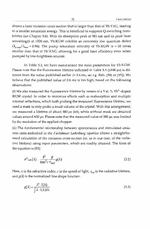
- 33- CHALLENGES
shows a laser emission cross-section that is larger than that of Yb:YAG, leading
to a smaller saturation energy. This is beneficial to suppress Q-switching insta
bilities (see Chapter 3.6). With its absorption peak at 981 nm and its peak laser
wavelength at 1026 nm, Yb:KGW exhibits an extremely low quantum defect
(A"ump/ A,aser = 0.96). The pump saturation intensity of Yb:KGW is = 10 times
smaller than that of Yb:YAG, allowing for a good laser efficiency even when
pumped by low-brightness sources.
In Table 3.3, we have summarized the main parameters for Yb:KGW.
Please note that the fIuorescence lifetime indicated in Table 3.3 (~OO Ils) is dif
ferent from the value published earlier (= 0.6 ms, see e.g. Refs. [58) or [59]). We
believe that the published value of 0.6 ms is too high, based on the following
observations:
(i) We also measured the fIuorescence lifetime by means of a 5 at. % Yb3+-doped
KGW crystal. In order to minimize effects such as reabsorption and multiple
internal reflections, which both prolong the measured fIuorescence lifetime, we
used a mask to only probe a small volurne of the crystal. With this arrangement,
we measured a lifetime of about 380 ll5 [60), while without mask we obtained
values around 600 Ils. Please note that the measured value of 380 IlS was limited
by the resolution of the applied chopper.
(ii) The fundamental relationship between spontaneous and stimulated emis
sion rates embodied in the Füchtbauer-Ladenburg equation allows a straightfor
ward calculation of the emission cross-section (or, as in our case, of the radia
tive lifetime) using input parameters, which are readily attained. The form of
the equation is [63):
L A2 ßC1 em(A) = -2-g(A)
8nn c 't'rad(3.2)
Here, n is the refractive index, c is the speed of light, 't'rad is the radiative lifetime,
and g(A) is the normalized line shape function:
A- A3 .I(A)g( )- fA'I(A)dA
(3.3)

CHAPTER3 -34-
I(,t) is measured in experirnentally relevant units of watts per wavelength inter
val. In this type of analysis, one must also know the branching ratio ß for the
considered transition. By using Equations (3.2) and (3.3) and assuming a value
of 1 for ß, we can deduce a theoretical upper limit for the radiative lifetirne of
about 300 J.1S12.
3.2.2 Neodymiurn-doped materials
Nd3> was the first of the trivalent rare earth ions to be used in a laser, and it re
mains by far the most important element in this group. Stimulated emission has
been obtained with this ion incorporated in at least 40 different host materials,
whereupon the principal host materials are YAG and glass. As only glass shows
a bandwidth that supports femtosecond pulses, we will take a doser look only
at Nd-doped glasses in the following. For a summary of other Nd-doped hosts,
please refer to Ref. [45).
3.2.2.1 Nd:glass
The first use of a Neodymium-doped glass was reported by Snitzer in 1961,
when he demonstrated that laser action was feasible [64). Over the years,
Nd:glass-based systems have tended to involve lasers dedicated to generating
high single-shot energies, high average power, or ultrashort pulses. All three of
these areas have continued to experience large interest to the present day. For
example, high-energy (ps and ns) pulsed Nd:glass lasers have been utilized
predominantly for plasma physics and inertial confinement fusion experiments
(see e.g. Ref. [65]). Continuing interest in this area has led to lasers evolving from
= 1 kJ to = 100 kJ - these systems are expected to reach the megajoule dass
within the next decade (see e.g. Refs. [65] and [66]). The general situation is that
Nd:glass is a technologically important means of generating laser radiation near
1.05 J.1m.
12 As Yb:KCW shows polarization-dependent emission cross-sections (see Table 3.3), we have used theaverage va1ue of the three emission cross-sections to determine the radiative lifetime.

- 35-
--!aser p~ertiesLaser wavelength A.em• max
Emission bandwidth KA.Emission cross-section (J \mAbsorption wavelength A.abs max
Absorption cross-section (J i'abs
Fluorescence lifetime 't<ad
Optical propertiesRefractive index at A.em max
Temperature coefficie~tof refractive index dn/dT (20°C to40°C)
Thermal propertiesThermal conductivity K (25 0c)Coefficient of linear thermal expansion a..,- (20°C to 40°C)
~echanicalproperties
Young's modulus EPoisson's ratio v
Table 3.4: Parameter.; for phosphate-based loser glasslJ
Unitspmnm
10-20 cm2
nm10-19 cm2
J.ls
Units
UnitsW/m·K
10-6 K '
Units109 N/mz
CHAllENGES
1.053519.64.2808
~350
1.508-6.8
0.612.5
53.70.267
There are several representative types of Nd-doped glasses that are
potentially useful including silicates, phosphates, and fluorides, as weil as
mixtures of these basic types (see e.g. Ref. [67]). The simplest glass into which
Nd can be incorporated is fused silica, or Si02 . An important step in laser
glasses occurred 1967 when phosphate-based compositions were first ex
plored [68]. Phosphates were found to have several important advantages over
silicate glasses (see Table 3.4) as e.g. a higher emission cross-section. In addition,
it can be manufactured free of platinum inclusions (which greatly increases the
optical damage threshold). Since micron-size platinum inclusions appear to be
an inevitable consequence of today's glass melting technology, it is of crucial
significance to note that it is possible to completely eliminate these particles by
treating phosphate glasses chemically. It has not yet been possible to achieve
comparable results for silicates or fluorides. Therefore, Nd:phosphate glasses
are generally regarded as the medium of choice for most bulk laser applications
IJ Data taken from Ref. [67] for the phosphate-based laser glass LG-760.

CHAPTER3 -36-
(see Chapter 4.2.1). In Table 3.4, we have summarized the most important pa
rameters for a phosphate-based laser glass.
3.3 Thermal effects in the gain medium
3.3.1 Introduction
The average output power obtainable from a solid-state laser is ultimately lim
ited by stress fracture due to heating of the gain element. At average powers
below this stress-fracture limit, heating can lead to thermo-optic aberrations,
thermallensing, and/or stress-induced birefringence that reduce the efficiency
of laser operation, decrease the output beam quality, and change the resonator
stability with pump power. In solid-state lasers, the primary source of heating
(at least in high quality laser gain media) is the quantum defect, which is de
fined as the difference between pump and laser photon energy. There mayaiso
be non-radiative relaxation due to parasitic losses such as non-radiative sites
(also known as "dead sites") which are sites that absorb pump photons but do
not contribute to inversion, excited-state absorption, upconversion, and
quenching (see e.g. Refs. [43] and [45]). Thus, laser materials with a small differ
ence between the pump wavelength and the laser wavelength (i.e. with a small
quantum defect) are expected to have lower heating as long as parasitic losses
are weak.
The most obvious way to lessen the impact of heating of the gain ele
ment is to choose a gain media that generates less heat. However, other con
straints such as laser wavelength, pump wavelength, amplification band
width, ...etc usually narrow the number of possible laser media. Therefore, one
normally has to choose a gain media with non-ideal thermal properties. In or
der to reduce the influence of these non-ideal properties one has to apply spe
cial pumping and cooling arrangements. In Chapter 3.4, we will go into this
subject in more detail.
In the following, we will consider the cases of a rectangular (slab) and a
cylindrical (rod) geometry, as shown in Figure 3.2, and deduce equations for

- 37- CHALLENGES
temper-ature rise (see Chapter 3.3.2), thermal-induced stress (see Chapter 3.3.3),
and thermallensing (see Chapter 3.3.4).
d
(a) (b)
3.3.2
Fi~e 3.2: (a) Slab for a Iaser with eIliptical mode geometry; (b) cylindrical rod geometry.
Temperature rise
Here, we consider the maximum temperature rise in the gain medium with re
spect to the cooled surface. While thermal-induced stress and thermal lensing
arise from temperature gradients on1y, the maximum temperature rise deter
mines the operation temperature of the laser medium. For some (typicaUy four
level) laser media this quantity is not of great relevance, but at elevated tem
peratures the efficiency of three-level laser media like Yb:YAG (see Chap
ter 3.2.1.1) or Yb:KGW (see Chapter 3.2.1.2) is reduced. Other gain media Iike
e.g. Cr:LiSAF show quenching effects [44]. For such lasers it is therefore cruciaI
to keep the maximum temperature as low as possible. This can be done with
special pumping arrangements (see Chapter 3.4).
We first consider the cylindrical rod geometry (see Figure 3.2(b», for
which anaIytical solutions are readily avaiIable [45, 69]. If we assume the power
PWs to be dissipated uniformly within a radius W beam from the rod center (with
Woo.m S; Rg), we obtain a temperature rise
öT =~(1+2ln~)max 4n:KL
gw
beam
(3.4)

CHAPTER3 - 38-
of the rod center with respect to the outer surface, where K is the thermal con
ductivity of the medium. We conclude that for a given material, L1Tm.x is largely
controlled by the quantity PclislLg, and the only way to substantially decrease
L1Tm.x is to increase the length Lg. Limits to this can be set by the beam diver
gence (particularly if the pump beam has a poor beam quality), by the avail
ability of long crystals, or by nonlinear effects in pulsed lasers, for example.
In the case of the rectangular geometry (see Figure 3.2(a)), we assurne
for a rough estimate that the pump beam fills the full width a of the slab, that
the pump profile is approximately flat in x direction, and that the extension of
the beam in y direction is small compared to the thickness d of the slab. This re
sults in the simple equation
(3.5)
We see that for a given material (which determines the value of K) and length
Lg, we can decrease L1Tm • x by decreasing the ratio dia. Such an option is not
available in the rod geometry. This result is qualitatively still the case if the as
sumptions made are not strictly valid. As a higher precision is usually not es
sential for this purpose, we resort on more precise numerical solutions only in
the following sections.
3.3.3 Thermal-induced stress
The stress that is induced by the inhomogeneous temperature distribution in
the gain medium can lead to stress fracture, and also have optical effects be
cause of its influence on the refractive index. In this chapter, we consider only
the problem of stress fracture. Optical effects of stress are treated in the next
section.
Again, we first consider the cylindrical geometry, for which analytical
solutions are available [45, 69). As before, we assume the power Pd;'; to be dissi
pated uniformly within a radius Wb•am (with W beam ~Rg). The maximum tangen
tial stress at the rod surface is

wheJre
- 39- CHALLENGES
(3.6)
lXr is the thermal expansion coefficient,
E is Young's modulus, and
v is Poisson's ratio.
As with the maximum temperature rise, we see that for a given material a sig
nific.ant reduction of stress is possible only by increasing the length L g• Equa
tion (3.6) can also be written by means of the thermal shock parameter Rsluxk (see
Equation (3.1))
Pdis (2 - W""'m
2 J= 4n:k'L R 2 "'shockg g
(3.7)
For the slab geometry, we first discuss the situation in which the slab is
uniformly pumped over its whole volume. In this case, we can write for the
maximum tangential stress [45]
or, (3.8)
(3.9)
For a given material and given Pdis/Lg, the stress can be reduced by reducing the
ratio d/Q. This is remarkable as e.g. areduction of d alone leads to an increased
density of dissipated power.
For the more difficult situation where only part of the slab is pumped,
we have used the program SOUDIS [70] to solve the heat conduction equation
numerically. We have assumed the pump beam to have the Gaussian radii w.
and wy in x and y direction, respectively. First, we investigated the dependence
of the maximum surface stress on wy' while w. and Pdis are kept constant. Fig
ure 3.3 shows that the dependence of both LiTm.x and Gm• x on wy is weak. Then
we varied w. (see Figure 3.4) and found that LiTm.x and Gm• x depend largely on

CHAPTfR3 - 40-
Pw./Wx' Therefore, we conc1ude that, as in the uniformly pumped slab, the stress
mainly depends on Pdis·d/(W.LJ apart from material parameters.
200 250 o-l-;u ~
9~ 150 ~ • 200 1l...
• l\lul • 150 ~!Il -QJ • ~.l::l 100 f--- - • .- ~!Il • X
§ • - 100 g.5 '"SO
50ö'
x - .?«l
~I I I I I ~0 0
0 100 200 300 400 SOO 600
Vertical beam radius, (J.1ffi)
Figure 3.3: Calculated maximum temperature rise and stress in a Nd:glass (Schott LG-760)
slab (with L, = 7.5 nun, a = 7.8 mm, d = 1 mm, and 4 W of dissipated power) as function of
the pump beam width in y direclion.
400 . 500 o-l~-;u 9
~ - 400 "0300 ~...
• l\l
ul • ~!Il - 300QJ ~
.l::l 200 - ~!Il X
§ • - 200 g.5 '"100
_.ö·
~ • - 100 .?~ • .-
0 I I I -I0 :8
0 1000 2000 3000 4000 SOOOHorizontal beam radius, (pm)
Figure 3.4: Calculated maximum temperalure rise and maximum stress as in Figure 3.3, but
with lhe pump beam widlh in x direclion as variable parameter.
To minimize stress fracture, we should therefore use a siab as thin as
possible and choose W x large enough. A small value of wy is beneficial because it
limits the required magnitude of d and aUows to increase W x without making
the mode area (and thus the laser threshold) excessively large. The optimum
value of wy will often be limited by the divergence of the pump beam. Thus, a

- 41 - CH/ILLENGES
pump source with good beam quality in y direction can help to decrease both
the temperature rise and the stress by using a thinner crystal. High power diode
bars, the currently most powerful pump sources available, happen to have just
this quality: While the beam quality factor M2 is typically » 1000 in the hori
zontal direction (where our demands for a slab geometry are very moderate),
we typically have M2 < 10 in the y direction, enabling tight focusing in this di
rection and thus the use of a rather thin crystal.
3.3.4 Thermallensing
The inhomogeneous temperature distribution in the gain medium may lead to
thermallensing due to several reasons (45). The refractive index is directly in
fluenced by the local temperature, and it is also affected by thermal-induced
stress. Moreover, stress can deform the end surfaces of the gain medium, which
gives another contribution to thermal lensing. Which contributions are domi
nant, depends on the gain material as well as on the geometry. Therefore, we
wiU discuss the situation for different lasers.
a) Yb:YAG laser
Recently, we have demonstrated a mode-Iocked high power Yb:YAG laser
based on the elliptical mode geometry (see Chapter 4.2.2) with up to 8.1 W of
average output power. Here we discuss the strong thermal effects in this laser
and derive some general conclusions from this analysis. First we cakulated the
temperature and stress distributions and the bulging of the end faces of the
d =0 1 mm thick, a =0 9 mm wide and Lg =0 4 mm long Yb:YAG slab for a total dis
sipated power of 1 W, using the program SOUDIS [70]. The heating power
density was assumed to be proportional to the local pump intensity. The simu
lation was carried out for different pump intensity distributions. Then, we used
the obtained data to calculate the refractive index profile, taking into account
both temperature and stress effects [45, 71). Finally, we obtained the phase re
tardation f{i...x,y) along lines in z direction by simple integration, and calculated
the thermal lens power in x and y direction from this. The material data were
taken from Refs. [45,69] and [56).

CHAPTER3 - 42-
For the first simulation, we assumed the pump profile to be Gaussian in
x and y direction with W z =1.2 mm and wy =80 pm (neglecting divergence a10ng
the z direction), centered in x and y direction. ln the second and third simula
tion we assumed super-Gaussian functions 1- exp[-2(x/w",)5] in x direction
with s = 3 and s =6, respectively, and calculated w., so that the peak intensity as
weil as the second moment of the intensity distribution stays the same as be
fore. Experimentally obtained pump profiles (which we generated with a high
power diode bar and cylindrical optics) were characterized with a CCD camera
and found to be elose to the super-Gaussian function with s = 6 near the focus,
while an ordinary Gaussian (with s = 2) is a better fit near the crystal ends. The
typical experimental situation effectively lies somewhere between s = 2 and
s = 6. The pump absorption along the z direction with an absorption length of
3 mm is taken into account. Figure 3.5(a), (c), and (e) show the resulting tem
perature distributions. They do not perfectly reflect the pump intensity distri
butions because the crystal thickness disnot much smaller than the pump beam
width. The solid curves in Figure 3.5(b), (d) and (f) show the resulting values
for the local thermallens focal power1.-' in x direction, calculated (always for a
single pass through the crystal) from the second derivative of the phase ql.x,y)with respect to x. For the Gaussian profile (see Figure 3.5(b»'/z·' has its maxi
mum (0.21 m· l) at the center, while for the super-Gaussian with s = 6 (see Fig
ure 3.5(f» maximum lensing (0.17 m· l) occurs in the wings because the tem
perature profile is quite f1at near the center and steeper in the wings. The other
curves in Figure 3.5(b), (d) and (f) show the different contributions to thermal
lensing. In both cases, the effect of stress on the refractive index somewhat
counteracts the direct temperature effect and the effect of bulging of the end
faces. The most interesting conelusion is that for a pump profile with s z 3,
which is quite realistic for real situations, the resulting values of1;1 are nearly
constant over much of the pump beam width. Th1S means that the effect of ab
errations can be quite small if only the laser mode size is chosen to be some
what smaller than the pump mode size (so that the laser mode does not probe
the regions of strong aberration in the wings of the pump profile). lndeed, our
Yb:YAG laser was found to have the best beam quality when the laser mode ra
dius in x direction was around 0.9 mm (see Chapter 4.2.2), to be compared with
a pump beam radius around 1.2 mm.

- 43- CHALLENGES
=~~T I•..•. Stress /- - [);spl.
I
-0.1 L-_---I.__-'--__...L._---:'
-2000 -1000 0 1000 2000
x, (~m)
(b)
...'.,~ 0.1o0..bO.5~~~
20001000oX, (~m)
(a)
-1000
5.-------....------,g.,' 4<Il·e., 3
.2 2~0..E.,
f-o
"-~
\
\\
.... ,.>..•.
-Total /......... dn/dT..... Stress /- - Displ.
/
-0.1 L---'>.""-I.__-'--__.-C>'""'-----:'
-2000 -1000 0 1000x,(~)
(d)
S' 5 0.2
~l!l.~
....,~ 0.1o0..
'" bO
1: J20001000o
x,(~)
(c)
-1000
.,'·C.,.2~0..
~f-oO_-=._L-_---'~ _ __l._"""_
-2000
.,;·C
~~0..
~ (.-"""':..:....JL-_--'__--'--'-='",.-<-;000 -1000 0 1000 2000
x,(~)
(e)
-2000 -1000 ox,(~)
(f)
1000 2000
Figure 3.5: (a) Calculated temperature profile in x dineclion at y =z =0 mm for a 4-mm long
Yb:YAG slab with 1 W of dissipated power. The pump profile is Gaussian with
w. = 1200 I'm and w, =80 I'ID. (c) Like (a), but with super-Gaussian profile (s =3) inx direclion (see text). (e) Like (c), but with s = 6. (b) Local thermal lens focusing power in
x dineclion for a Gaussian pump profile as in (a). Truck solid line: Total inverse focal length.
Other curves: Pump beom profile, as weil as the different contribulions from the direct
thermal effect (dn / dT) on the refraclive index, from stress, and from bulging of the end
faces. (d) and (f) Like (b), but with super-Caussian profiles s = 3 and s = 6, respectively.

CHAPTER3 - 44-
The thermaliens focusing powerf/ in Y direction (see Figure 3.6) is sig
nificantly stronger, about 1.8 m·1 in the beam center. lt is irnportant, however, to
realize that nevertheless thermal lensing in y direction constitutes a much
smaller problem than in x direction because the laser mode size in y direction is
much smaller, and smaller modes are less sensitive to focusing effects (see
Chapter 3.5). As shown in Ref. [36], the width of the stability ranges of a stand
ing-wave cavity with respect to the thermaliens focusing powert' is 2)./(=02),
where Wo is the mode radius in the gain medium at the stationary point
(= minimum) of the stability range. In our case, the width of the stability range
in y direction is more than 2 orders of magnitude larger than in x direction
while the thermaliens is only about one order of magnitude stronger". Indeed,
we found it much easier to obtain a good beam quality in y direction, despite of
the largerf/ .
F
10050-50 0
x, (pm)-100
3-Total / \ •
~ ...... dn/dT / ......... ...........\ ..'7
5 2 •.•. Stress- . Displ. ,./ \....•.....' ....
aI "...•.~ ....00..bO 0.S ..........
a -10u.. ..
-2
Figure 3.6: Like Figure 3.5(b), but for the y di.rection.
We also found that the thermal behavior of the Yb:YAG laser was
somewhat improved by using a vertical offset of the pump beam from the cen
ter position. A simulation revealed that in this asymmetrie situation (with a
vertical offset of 300 pm) the temperature rise is reduced by one third and the
thermallens power by one fifth. The finding indicates that the thickness d could
actually be made somewhat smaller without increasing the diffraction 1055 too
I< Another way to explain Ws dependenee on mode size is that a larger mode aequires a higher phaseshift in its wings, because e.g. for a not aberrated lens in x direclion the phase shift is proportional tox'//. (see Equation (4.3)).

- 45- CHALLENGES
much. This should decrease the temperature rise, stress, and the thermal lens
power in x direction. We tried this with a reduced crystal thickness of 0.6 mm,
but achieved a lower output power, apparently because the reflecting coating
was not good enough so dose to the edge of the crystal.
b) Nd:glass laser
As another example, we consider the case of Nd:glass high power lasers as de
scribed in Chapter 4.2.1 and in Refs. [72] and [73]. The dimensions of the gain
medium, a slab made of Nd-doped Schott LG-760 phosphate glass (see also
Table 3.4), are similar as for the Yb:YAG laser: d = 1 mm, a = 7.8 mm, and
Lg = 7.5 mm. We used material data from the manufacturer [67], except for the
photoelastic coefficients, for which we used data of a similar phosphate glass
Q - 88 from Ref. [56].
~60
~50
.~ 40
] 30
'" 20...cu
~ 10
~-1000 0 1000
x, (I.un)
(a)
2000 -1000 0x, (I.un)
(b)
1000 2000
Figure 3.7: Like Figure 3.5(e), but for Nd:glass and WB = 1300 }.l1I\.
Figure 3.7(a) shows the temperature distribution in the Nd:glass gain
medium for 1 W of dissipated power. We assumed a super-Gaussian pump
profile in x direction with s = 6 and a width of w., =1300 pm (as in the experi
ment). The temperature rise is much larger than in YAG because of the ~ 21
times poorer thermal conductivity. However, Figure 3.7(b) shows that the
negative value of dn/dT (a characteristic of the phosphate glass) allows the di
red lhermal effect on the refractive index to cancel most of the effect caused by
stress. Mainly for this reason, the thermallens focusing power is only ~ 4 times
stror.ger than in YAG for the same dissipated power. Another factor is that the
four-level nature of Nd:glass allows working with a somewhat larger mode

CHAPTER3 - 46-
area, which reduces the effect of thermallensing. The main problem in the end
is the tendency for stress fracture, which we indeed experienced a few times in
our Nd:glass laser experiments but never with the Yb:YAG laser, despite of sig
nificantly higher output powers.
3.4 Purnping schemesAs long as pulses with > 5 ps duration are wanted, one can resort to gain media
such as Nd:YAG or Nd:YVO., which have rather favorable thermal properties.
Traditional rod geometries, used with either end purnping or side pumping,
can then be used to generate high output powers [74, 75]. Currently available
diode-pumpable gain media with larger amplification bandwidth, however, re
quire special solutions for high-power operation due to their poor thermal
properties (see Chapter 3.2).
In the following sub-sections, we will discuss three optimized purnping
geometries, which already have shown their suitability for pumping of high
power lasers. In addition, we will also try to evaluate their potential for power
scaling.
3.4.1 High-brightness15 pumping
This pumping scheme is typically used for pumping of low-power lasers. The
major problem that arises by using Ws pumping scheme for high-power lasers
is that the output power of high-brightness pump diodes is limited to a few
watts so far. This also restricts the possible femtosecond output power to this
regime. In addition, due to the high pump intensities, it is not suitable for gain
media with low thermal conductivity such as e.g. glass.
" The brightness B is a measure for the maximum achievable pump intensity and is defined as power/unitarea!unit solId angle. For a laser beam with wavelength ~. power p. and beam quality faclors M, 2 and M.,'the brightness becomes:
B=--PA.2M;M:

- 47- CHALLENGES
iCavity mirror
Gain mediumI
r=+1--==:::-~-_:::---?'
Slow axis Sphericallens
Fast axis ~ _/ '"'" ------=-==-~~---
ASPhll'~ CYlin~2'11'~Cylindricallens
Figure 3.8: Typical high-brightness pumping scherne.
Figure 3.8 shows the basic properties of the high-brightness pumping
scheme. The two different axis16 of the diode are first collimated through an
aspheric lens. In standard laser cavities (without the use of cylindrical optics),
the laser modes inside the cavity are more or less round17 (see e.g. Ref. [76]).
Therefore, in order to achieve mode matching between laser and pump beam
(which is necessary for a good efficiency and a low laser threshold), the pump
beam has to be focused to a circuJar spot inside the gain medium. Generally, if a
lens is placed in the optical path of a laser beam with beam quality factor M,the transmitted beam is focused to a radius Wo given by (see e.g. Ref. [76])
2 )..wo~M --f·
ltWlens
(3.10)
Here, we have assumed that the radius of curvature of the beam at the lens (as
weil as the beam area at the lens divided by the wavelength, TUJJ1:m/)..) is much
targer than the focallength f (see e.g. Ref. [76]). Equation (3.10) shows that the
beam radius behind a lens of given focallength fand at fixed wavelength ).. is
proportional to M / W 1ens' Therefore, in order to achieve a round spot behind
the spherical focusing lens (see Figure 3.8), the pump beam has to be flared in
slow direction by the ratio of the beam quality factors, M 2stow / M2
fast • This
expansion is typically achieved by means of a cylindrical (Keplerian or
Galilean) telescope (see Figure 3.8).
16 The axis of a laser diode parallel to the diode junction is normally called fast axis, while the di.rectionperpendicular 10 the diode junction is named slow axis.
11 It has to be noled that the cavity mode already has an aspect ralio of n (where n is the reiraclive index ofthe gain medium), if a Brewster-eut medium is used.

CHAPTER3 - 48-
Due to the high brightness of the diode, one can focus the pump to a
small area, which leads to high pump intensities in the gain medium. This is
especially required for quasi-3-level systems in order to more easily overcome
the transparency intensity. We recently have obtained more than 1 W of
average output power from an Yb:KGW laser pumped with a high-brightness
pumping set-up (see Ref. [77] and Chapter 4.1.2). In this experiment, we were
limited only by the available pump power.
3.4.2 Elliptical mode approach
Here we describe an approach that has been applied first to Cr:LiSAF [78] and
has recently been proven to be successful with Nd:glass [72] and Yb:YAG [79]
(see Chapter 4). The spatial profile of the output of typical high-power diode la
sers (with tens of watts) is very asymmetrie in terms of beam size and mode
quality; while M"last is < 10 in the direction parallel to the diode junction (fast
axis), it can be » 1000 in the perpendicular direction (slow axis). To achieve the
highest possible pumping efficiency (or equivalently, small-signal gain), we
have to focus the pump beam to a pump spot area that is as small as possible,
while maintaining a good overlap of the pump beam with the laser mode over
at least an absorption length. Therefore, the generation of a focused circular
spot without a significant loss of brightness requires the use of some beam
shaper [80l, which symmetrizes the beam quality in both directions. Our ap
proach, however, involves focusing the beam with cylindricallenses so that the
confocal parameters!8 blas. and b sJow for both directions are in the order of the ab
sorption length Labs of the crystal:
(3.11)
The resulting strongly elliptical beam can be used to pump a gain medium with
only ~ 1 mm thickness or less. Such a thin gain medium can be cooled effi
ciently from the top and bottom sides (see Figure 3.9), which limits the maxi
mum temperature rise (see Chapter 3.3.2). This is beneficial particularly for gain
media like Yb:YAG or Cr:LiSAF, which are less efficient at elevated tempera-
" The confocal parameter b is defined as b ~ 2·z. ~ 2·m",' / .1. [4] (w,: radjus of beam waist), where theRayleigh range z. ~ =,'/ .1.14J describes the distance whjch the beam travels from the waist before thebeam radius increases by .fi. (or before the beam area doubles.)

- 49- CHALLENGES
tures. Moreover, if the width of the pump beam is larger than the crystal thick
ness, the resulting heat flow is nearly one-dimensional, and the temperature
profile roughly resembles the intensity profile of the pump beam. If the latter is
relatively flat in the long direction, the focusing power of the thermaliens in
this direction (which is the more critical one) is significantly reduced. Unlike
cylindrical rod geometries, this geometry is in principle power scalable. Dou
bling the power as weil as the width of the pump beam leads to a four times
weaker thermal lens, while the two times wider laser mode is four times more
sensitive to thermallensing19. Thus, the width of the stability range of the cavity
in terms of pump power can be increased together with the pump and output
power.
Pump beam Laser mode
Figure 3.9: Elliptical geometry for high-power lasers with thermaJly challenging materials.
T... and TM' denote the temperature variation in tangential (horizontal) and sagittal (vertical)direction.
3.4.3 Thin-disk approach
A to:ally different approach, which looks very promising at least for a limited
ran~ of laser materials, is the thin disk-concept [81, 82). Here a circular rod ge
omelry is used, however with a very small dimension « 1 mm) in the axial di
rectiDn and cooling through one end face (rather than transverse cooling) (see
Figu:e 3.10). In this geometry, the temperature rise at a given distance from the
symmetry axis is largely determined by the local pump intensity and the dis
tance from the cooled end surface. The pump intensity distribution can be con
trolltd so that thermallensing is reduced weil below the level that is typical for
con ntional rod lasers. The pump absorption in a single pass through the thin
" Thewidth of a cavity slability zone in terms of focal power of the thermal lens is inversely proportionalto Ue square of the mode size at the position of the thermal lens (see Chapter 3.5 and ReI. [36]).
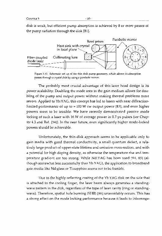
CHAPTER3 -50-
disk is weak, but efficient pump absorption is achieved by 8 or more passes of
the pump radiation through the disk [81].
Fiber coupleddiode laser
RoofprismHeat sink with crystal ~in focal plane~ "<'?~:cP----:l~..LLl
/%
Figure 3.10: Schematic set-up of the !hin-disk pump geometry, which alIows 16 absorption
passes through a crystal disk by using a parabolic mirror.
The probably most crucial advantage of this laser head design is its
power scalability: Ooubling the mode area in the gain medium allows for dou
bling of the pump and output power without making thermal problems more
severe. Applied to Yb:YAG, this concept has led to lasers with near diffraction
limited performance of up to =100 W cw output power [83], and even higher
powers seem to be feasible. We have recently demonstrated passive mode
locking of such a laser with 16 W of average power in 0.7-ps pulses (see Chap
ter 4.3 and Ref. [54]). In the near future, even significantly higher mode-locked
powers should be achievable.
Unfortunately, the thin-disk approach seems to be applicable only to
gain media with good thermal conductivity, a small quantum defect, a rela
tively large product of upper-state lifetime and emission cross-section, and with
a potential for high doping density, as otherwise the temperature rise and tem
perature gradient are too strong. While Nd:YAG has been used [84, 85] (al
though somewhat less successfully than Yb:YAG), the application to broadband
gain media like Nd:glass or Ti:sapphire seems not to be feasible.
Oue to the highly reflecting coating of the Yb:YAG disk on the side that
is attached to the cooling finger, the laser beam always generates a standing
wave pattern in the disk, regardless of the type of laser cavity (ring or standing
wave). Therefore, spatial hole burning (SHB) [86] unavoidably occurs. This has
a strong effect on the mode locking performance because it leads to inhomoge-

-51- CHALLENGES
neou.s gain saturation. We will go into this subject in more detail in Chap
ter 4..3.1.
3.5 Laser cavity designThe esign of a laser cavity strongly influences the sensitivity of the laser to
thermal effects (see Chapter 3.3). A central chaUenge is that the strength of the
thermaliens varies with pump power, and to some smaller extent also with the
Variable lens f
Figure 3.1 1: Linear resonator with an intemallens of variable focallength f and other intra
cavity optical systems. In our case, the lens f is formed by the thermal lens inside the gain
medium. The dashed Iines are reference planes as used in Figure 3.12.
intracavity laser intensity. A standing-wave resonator with a single variable
lens (see Figure 3.11) has in general two stabili ty zones, calied zone I and zone II
[36] (see Figure 3.12). Zone II is defined as the zone in which the mode sizes on
both end mirrors of the cavity diverge at one of the stability limits (see Figure
3.12). In our case, the variable lens fis formed by the thermal lens inside the
gain medium. Stable cavity modes exist if the focusing power of the thermal
lens lies in one of these two zones. The minimum fundamental mode radius W3Q
inside the gain medium is the same for zone I and zone II. The width of both
zones in terms of focusing power is given by (see Ref. [36])
(3.12)
For stable operation with good beam quality, it is advantageous to operate the
laser near the minimum w3Q of mode size in the laser medium, because then the
spot size is less sensitive to changes of the power level.

CHAPTER3
(a)
- 52-
w,
w.(b)
Zone I
Zon~I
Zone II
\ Zone II )
_.._...\~V
f'
(e)
~W, W.lr::J· .· .· .
f'
I+-- M'--J f'
Figure 3.12: Spot radius of a !inear cavity (as shown in Figure 3.11) with an interna! variable
lens (Figure laken &om Re!. [36]). (a) Mode radius on mirror \. (b) Mode radius on mirror 2.
(c) Mode radjus on lens 3. The dashed vertica! !ines correspond 10 the mliUmUffi funda
mental mode radius WJO inside the gain medium.
Moreover, it was shown [36] that the alignment of the cavity is signifi
cantly more critical in zone II. At one edge of zone II, the sensitivity of the reso
nator against misalignment even diverges; this edge is always the one where
the mode sizes on both end mirrors diverge (see Figure 3.12). We note that in the
particular case where the variable lens is at one end of the cavity, only one sta
bility zone exists, and this is zone n in Magni's notation, i.e., it is always the one
with larger alignment sensitivity. (This can be shown with Equations (9) to (12)
in Ref. [36] by assuming a vanishing distance between the variable lens and one
end mirror.)

- 53- CHALLENGES
In our experiments on elliptical-mode Yb:YAG lasers (see Chapter 4.2.2)
we initially used zone-II cavity designs, but then we found that the alignment
stability was indeed greatly improved by changing from a zone-lI cavity to an
other one operating in zone I [79]. We believe that alignment sensitivity is par
ticularly important in lasers were the thermaliens is strong and has significant
aberrations. For example, by slightly moving the pump beam in transverse di
rection, the center of the thermaliens moves away from the beam axis and thus
has a similar effect as a tilt of a mirror. If the laser modes react to this with a
strong change of mode position (which can in turn again influence the strength
and shape of the thermal lens), the alignment becomes very critical, even if
good mechanical mounts are used. With the initial zone-lI cavities, we some
times observed hysteresis effects, where for example the laser power could not
be reproduced after just blocking the pump beam for a moment. This tendency,
which makes the alignment very difficult, was found to be much reduced with
a zone-I cavity design.
The question then arises how to find a suitable cavity design operating
in zone I. We have already seen that a standing-wave cavity with the thermal
lens at one end always has to operate in zone lI, because zone I requires an ar
bitrarily strong thermallens if one arm length goes to zero. Therefore, a cavity
type with two arms has to be taken. Such a cavity is also more suitable for a
mode-locked laser because it gives the freedom to put the output coupler at one
end (generating a single output beam) and the saturable absorber on the other
end (which makes focusing on the absorber more convenient). A disadvantage
of this cavity type is that the beam makes four instead of two passes through
the gain medium per round-trip, doubling the effective strength of the thermal
lens (but also the gain).
However, the design of a suitable cavity operating in zone I is a difficult
task because several conditions have to be fulfilled. The laser mode sizes in the
gain medium have to have given values in both directions, and particularly in x
direction the operating point should be not too far from the point of minimum
mode size. Sometimes, the mode sizes at other positions have to meet addi
tional conditions, e.g. to get the right spot size on a saturable absorber in a
mode-locked laser. We note that if a zone-lI design is known that meets all

CHAPTER3 -54-
these requirements, it can not be easily transformed into a zone-I design by
continuous adjustment of the parameters, because both zones are separated by
an unstable region (see Figure 3.12), and there are singularities at the ends of the
stability zones.
In this situation we have developed a strategy to find a zone-I design
meeting all mentioned requirements. The implementation of this strategy lead
to a self-made computer program, which is based on a combination of analyti
cal results with a nurnerical optirnization aIgorithrn. For adescription of the ba
sic ideas of this program, please refer to Ref. [87].
3.6 Q-switching instabilitiesIn a passively mode-Iocked laser, the saturable absorber needed for mode
locking also introduces a tendency for Q-switching instabilities. This can drive
the laser into the Q-switched mode-locked regime with mode-locked pulses
under a Q-switched envelope [88, 89). Recently, Hönninger et al. have investi
gated in detail the transition between the regimes of stable cw mode locking
and Q-switched mode locking (QML) [90]. Here, we discuss the impact of this
issue on the development of passively mode-locked high-power lasers, which
turn out to be more affected by this problem than most low-power lasers. For
picosecond lasers, not operating in the soliton mode-locked regime, they found
the condition [90)
(3.13)
for stable cw mode locking. Here, Ep is the intracavity pulse energy,
Et..sat =hvAL/(mer\m) is the effective saturation energy of the laser medium and
AL is the mode area in the laser medium. m is the nurnber of passes through the
gain medium per cavity round-trip. They assumed a slow absorber with
modulation depth L1R, which is fuHy saturated by the intracavity pulse
(Ep > 3EA,sa,). Here we rewrite this criterion by introducing the saturation pa
rameter

ES=-P-
EA•sat
and obtain
- 55- CHALLENGES
(3.14)
(3.15)
The pulse energy Ep enters this equation both directly and indirectly (via 5), but
this form of the equation is useful for the following discussion. The problem
with many high-power lasers is that the ratio Ep / EL• sat is relatively smalI, mainly
because the poor beam quaIity of the diode pump laser and/or the use of
schemes like side pumping tend to increase the laser mode area AL more than
the pulse energy. To some extent, QML can still be suppressed by using a small
value of L1R, just enough for mode locking, although this typically leads to
longer pulses. Another option is to saturate the SESAM more strongly, i.e., to
increase S. This can also affect the pulse duration, and eventually lead to
SESAM damage (normally for 5 > 100; see Chapter 3.7). Typically, we use
5 ~ 3...5 in low-power lasers, while the suppression of Q-switching instabilities
has made it necessary to use values of up to S ~ 27 in high-power lasers [91]. Fi
nally, for given values of L1R and 5 we can increase the intracavity pulse energy
Ep by using an output coupler with smaller transmission. This, however, will
eventually compromise the laser efficiency and increase the dissipated power
on the SESAM. An often better way of increasing Ep is to use a longer laser cav
ity with smaller repetition rate.
A somewhat unexpected result is that the choice of laser material as
weil as the construction of the laser head has an indirect (hut strong) effect on
the problem of SESAM damage (see Chapter 3.7). This is because for a laser
head with large saturation energy (i.e., with small cross-sections and/or large
mode area) the need to avoid Q-switching instabilities can enforce the operation
with high intracavity power (weak output coupling) and strong saturation of
the SESAM. Partly for this reason it is essential to use optimized purnping geo
metries and laser cavity designs (see Chapters 3.4 and 3.5) (particularly in the
domain of high powers, where not every laser head is equally suitable for pas
sive mode locking).

CHAPTcR3 - 56-
Another important finding is that operation in the solitor: mode-Iocked
regime (with negative overall cavity dispersion) substantially inaeases the sta
bility against QML [90]. Basically, this is because any increase in pulse energy of
a soliton increases the bandwidth and thus reduces the effective gain because of
the limited gain bandwidth. As most of the other measures against QML (as
discussed above) have unwanted side effects, the additional option of reducing
the QML tendency by operation in the soliton mode-Iocked regime (i.e., by
adding appropriate level of negative dispersion to the cavity) is very we1come.
While we only have to tolerate a slight increase of the intracavity losses (which
can be rather small), we can typically further reduce the pulse duration. This
technique was essential for stable mode locking of the Yb:YAG and Nd:glass
lasers, which we will describe in Chapter 4.
3.7 Damage of the saturable absorberIn passively mode-Iocked high-power lasers, an important issue is to avoid
damage of the saturable absorber. One possible cause for damage is that the ab
sorber may become too hot. We note, however, that absorber damage can also
be caused by non-thermal effects, particularly in the presence of Q-switching
instabilities (see Chapter 3.6), which can lead to the generation of very intense
pulses. Recently, we have started a detailed and systematic study of the dam
age thresholds and mechanisms for SESAMs. PreJiminary results show that no
SESAM damage occurs, if the applied fluences are within 100 times the satura
tion fluence FA, sat· Therefore, we can expect non-thermal effects to be under
contral if we do not operate the absorber with an excessively high saturation
parameter 5, and also manage to suppress Q-switching spikes. Thermal effects
will remain, and in Ws section we briefly discuss how to limit them. We do Ws
discussion for semiconductor saturable absorber mirrors (SESAMs; see Chap
ter 2.2), which have so far been used most successfully for mode locking of
solid-state lasers, although some results would apply to other absorbers as weil.
Each SESAM has both some saturable losses, which is needed for pas
sive mode locking, as weil as some unwanted nonsaturable losses. The latter
tends to be increased by low-temperature semiconductor growth, which is often

-57- CHALLENGES
used to reduce the recovery time of the absorber. It has been shown, however,
that the application of a suitable annealing procedure [92) or doping the semi
conductor with beryllium [93] can help to obtain a fast time response and low
nonsaturable losses at the same time.
Here, we discuss thermal effects on a phenomenologicallevel. If a pulse
with energy Ep hits aSESAM, the dissipated part of the energy is
(3.16)
provided that the SESAM is fully saturated, i.e. Ep > 3EA• so ,' Here, EA• so, is the
saturation energy, L1R is the modulation depth, and Rns is the reflectivity in the
fully saturated regime. Therefore, the heat dissipation is usually dominated by
the nonsaturable losses if the SESAM is operated in the regime of strong satu
ration, which is often needed to reduce Q-switching instabilities (see Chap
ter 3.6). Particular1y for high-power operation, it is therefore desirable to have
SESAMs with a small ratio of nonsaturable to saturable losses.
Of course, the maximum temperature on the SESAM also depends on
the size of the laser beam on the absorber. As long as the Gaussian spot radius
W A is smal1er than the thickness dA of the absorber, the maximum temperature
rise (in the center of the laser beam) is [73]
(3.17)
where Pdis is the dissipated average power and K is the thermal conductivity,
e.g. =45 W·K'·m-1 for GaAs. We have assumed that the whole backside of the
absorber is kept at room temperature. Scaling up the output power of the laser
usual1y involves a proportional increase of mode area 1W/ so that effectively
L1Tmax rises proportional to .JP:::- At some stage, however, W A becomes larger
than dM and the nearly one-dimensional heat flow leads to [73)
(3.18)

CHAPTER3 - 58-
where L1Tmax will no longer rise if the mode area is scaled up proportional to the
laser power. The most advanced high-power mode-locked lasers just begin to
get into this regime.
How large the mode radius W A on the SESAM has to be, depends not
only on the intracavity pulse energy Ep but also on the saturation energy EA• sa,;
in fact the mode-locking performance depends only on the saturation parame
ter S = EplEA,sa, (see Equation (3.14)). Therefore, it is advisable to use SESAM de
signs with a small saturation fluence (despite of their typically lower damage
fluence) and use an accordingly larger mode radius W A in order to limit the
temperature rise L1Tmax'
We see from this discussion that the problem of SESAM heating (or
SESAM damage, to be more general) will (in contrast to a still widespread be
lief) not necessarily become more severe as the output power is scaled up, pro
vided that suitable laser heads (with small gain saturation energy) and SESAMs
with low saturation fluence (for a large mode area on the absorber) are em
ployed. Therefore, we expect SESAMs to remain very suitable for passive mode
locking even of lasers with much higher average powers than demonstrated so
far.

Chapter 4
Experimental Results
So far, we have talked about the requirements that have to be fulfilled for
building a diode-pumped high-power femtosecond laser. In this chapter, we
now focus on the experimental results. We have subdivided this chapter into
three main parts, corresponding to the three different pumping schemes intro
duced in Chapter 3.4. Most of the results presented here had (or still have) been
record-breaking either in pulse duration (see e.g. Chapter 4.1.1) or in average
output power (see e.g. Chapters 4.1.2 and 4.3.1).
4.1 Lasers purnped with high-brightness diodes
4.1.1 60-fs pulses from a diode-pumped Nd:glass laser
Dur first experiment, which will be described in the following, mainly concen
trates on the question of the minimum achievable pulse duration from a
Nd:glass laser. This question is of great importance as it can help to achieve
high peak powers without the need for extremely high average powers. Multi
kW peak powers are beneficial for numerous applications. Examples are three
photon microscopy or z-scan measurements in the field of nonlinear spectros
copy, synchronous pumping of optical parametric oscillators for femtosecond
tunable IR sources, or efficient and simple UV generation by cascaded external
single-pass wavelength converters.
- 59-

CHAPTER4 - 60-
Typical Nd:glass laser materials have a fluorescence bandwidth of 20
30 nm FWHM (see Table 3.4), supporting sub-lOO fs pulse generation at a
wavelength of -1.06 pm. Until recently, the shortest pulses of 88 fs from a (bulk)
Nd:phosphate laser [94] were produced by additive pulse mode locking (see
Chapter 2.1). Semkonductor saturable absorber mirrors (SESAMs) in various
Nd:glass lasers [95, 96] have supported pulses as short as 130 fs for diode
pumping and 90 fs for Ti:sapphire pumping. Recently, we have demonstrated
60-fs pulses [97] from an optimized diode-pumped Nd:glass laser using
SESAMs. The ratio of the intracavity pulse energy fluence to the saturation flu
ence of the SESAM is shown to be an important design parameter in order to
avoid multiple intracavity pulses [27, 97]. Simple arguments can explain the oc
currence of double or multiple pulses at increased pulse fluence.
Figu.re 4.1: Intensity autocorreJation lrace (a) and optical speclrum (b) 01 the shortest pulses
oblained Irom a diode-pumped Nd:fluorophosphale g1ass laser (Scholt LG-81O). The dolled
curve in (a) is a fillo an ideal sech' pulse shape. The dolled curve in (b) shows the fluores
cence speclrum of the Nd:fluorophosphate g1ass, indicating that the pulse speclrum spreads
over most of the available gain bandwidth.
-100 0 100
Time delay, (fs)
(a)
1.02 1.04 1.06 1.08 1.10 1.12
Wavelength, (}.lm)
(b)
Figure 4.1 shows the experimental results of 60-fs pulses from a
Nd:fluorophosphate (LG-810 Schott laser glass [67], 3 % Nd-doping) laser at an
average output power of 84 mW, corresponding to a peak power of =11 kW
(total absorbed pump power, 1.1 W). We have also obtained 68-fs pulses from a
Nd:silicate laser glass (LG-680, 3 % Nd) at an output power of 32 mW (absorbed
pump power 0.37 W from both diodes). The spectrum of the 60-fs pulses is
21.6 nm wide (FWHM) and fills most of the available gain bandwidth of the
LG-8lO (see Figure 4.1(b». The time-bandwidth product is 0.34, within 10 % of

- 61 - EXPERiMENTAL RESULTS
the transform limit. These pulses were stable over an experimental period of
more than an hour. Mode locking was generally self-starting. The laser cavity
was easy-to-align and did not have to be operated dose to the resonator stabil
ity limit. Additionally, no hard aperture was present. This rules out Kerr lens
mode-locking [5] as a significant mode locking effect.
We have used an optimized low-finesse SESAM [98, 99] with a modu
lation depth L1R of 1 %. The bitemporal impulse response of the SESAM (see
Chapter 2.2.1) shows a fast time constant of 200 fs, followed by a slow time con
stant of 25 ps (as determined by a standard pump probe measurement). The
saturation fluence FA...1 of the used SESAM was measured to be 116 JlJ/cm2.
prism
SFlOprism
SESAM ROC=20cm
Output coupler
Figure 4.2: Set-up of the 6O-fs Nd:g1ass laser pumped by two high-brightness laser diodes.
ROC, radius of curvature of the spherically curved mlrroTS; SESAM, semiconductor satur
able absorber mirror.
The pump and cavity layout (see Figure 4.2) is based on a standard delta
cavity design similar to that of Ref. [96]. The laser beam is focused onto the
SESAM to a calculated beam waist of about 63 Jlffi x 70 Jlffi in radius. The cavity
repetition rate was typically 114 MHz. The calculated beam radius in the laser
material is approximately 47 Jlffi x 66 JlID. The Nd:glass laser is cw-pumped by
two diode lasers (Spectra Diode Laboratories, SDL-2360-C, 1.2 W, emitting
wavelength = 803 nm) focused to a beam radius of approximately
40 Jlm x 50 Jlm. The higher doping level and the reduced absorption length

CHAPTER4 - 62-
(2 nun) of the Nd:fluorophosphate, as compared to Ref. [96], result in improved
mode-matching of the pump beam to the laser mode over the absorption
length. The Nd:silicate glass (LG-680) used in some experiments had
3 % Nd doping with an absorption length of 2.5 nun at the pump wavelength.
We have chosen LG-810 and LG-680, which are inhomogeneously broadened,
because mode locking is obtained more easily than with the homogeneously
broadened Nd:phosphate laser glass [96].
In the experiments described above, we verified that a single intracavity
pulse was present. However, we observed a breakup into two or more pulses at
increased intracavity energy (see Figure 4.3), or at a decreased amount of nega
tive group delay dispersion, ID I, i.e. increased prism insertion (see Figure 4.4).
The spacing between the pulses in the cavity ranged from '" 90 ps to half the
cavity round-trip time, and was subject to spontaneous changes. We monitored
the pulse train with a fast 50 GHz photodiode and a 20 GHz samplingscope
(Tektronix CSA 803) with a time resolution better than 20 ps. Additionally, the
autocorrelation span was increased to > 20 ps to monitor possible smaller pulse
spacings. However, such smaller spacings were not observed.
Pulse fluence incident on SESAM, (pJ/ cm2)
100 150 200 250 300 350 400
120~
~ 110e0 JOO:c I
'" I...:::J 90 I-0CIl IrJl 80"3 I
Cl..70
20 30 40 50
Pulse energy, (n])
60
Figure 4.3: Dependence of the pulse duration on the total intracavity pulse energy in the
Nd:silicate glass laser (Schott LG-680). The data are litted assuming allE, behavior (as typi
ca! lor solitons (see Equation (4.1))). At an energy 0135 nj. the pulse breaks up into!wo intra
cavity pulses that have longer pulse durations.

- 63- EXPERIMENTAL RESULTS
Figure 4.3 shows the pulse duration as a function of the total intracavity
pulse energy Ep but at a constant negative dispersion in the Nd:silicate laser
(the fluorophosphate laser showed a similar behavior). As we increase the
pump power and thus the pulse energy Ep, the measured transform-limited
pulse duration decreases approximately inversely proportionally to Ep , as the
soliton mode locking model predicts (see Chapter 2.1 and Refs. [19,25]):
T =176. 210 1p . e5SPM ' Ep
Here, ClsPM is the so-called SPM coefficient, which is defined by
1e5SPM =knzLsPM-
ASPM
(4.1)
(4.2)
where k is the wave number, "2 is the nonlinear refractive index of the
SPM medium 20, LSPM is its length, and A SPM is the mode area of the laser beam
inside the SPM medium. In our case, the SPM medium is identical to the gain
medium. The observed deviation is most likely due to thermal lensing effects.
At sufficiently high Ep of =35 nJ (corresponding to =2.2-times FA. 50')' the intra
cavity pulse breaks up into two separate pulses, accompanied by a jump in
pulse duration by a factor of =2. Correspondingly, the spectrum narrows by a
factor of =0.5, as we would expect for a soliton with half the energy (see Equa
tion (4.1)).
For a fixed absorbed pump power of 658 mW in the Nd:silicate and an
intracavity pulse energy of 46 nJ, which corresponds to 2.8-times FA, 5Ol> we ob
served an analogous behavior as we increased the insertion of one intracavity
prism, thereby decreasing 101 (see Figure 4.4). The transform-limited pulse du
ration decreases for smaller 10 I, i.e. increased prism insertion, until it breaks
up into two pulses of Ionger duration. We could observe a linear dependence
both in the single and in the double pulse regime, weil in agreement with the
soliton mode-locking model (see Equation (4.1) and Refs. [19, 25]). At an even
smaller I0 I, we could also observe a transition to more than two intracavity
.. SPM medium = medium. in which a laser beam sees an inlensity-dependenl reffactive index due 10 theKerr effecl.
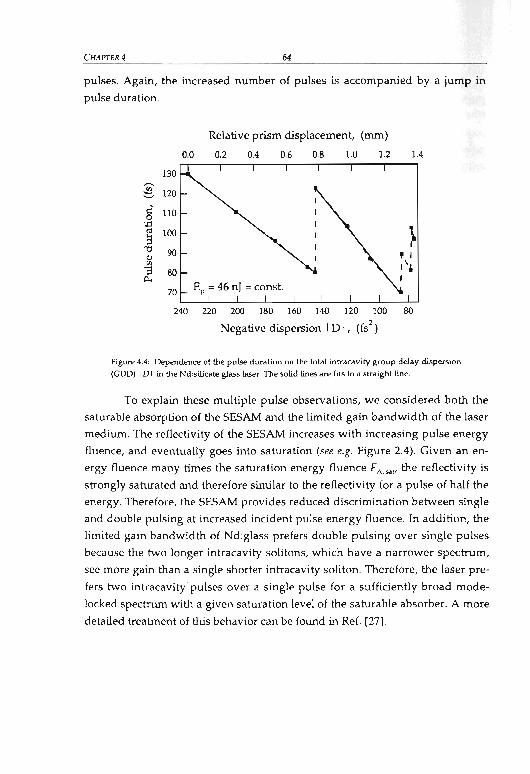
CHAPTER4 - 64-
pulses. Again, the increased number of pulses is accompanied by a jump in
pulse duration.
Relative prism displacement, (nun)
0.0 0.2 0.4 0.6 0.8 1.0 1.2 1.4
~
~1::'0
'.0
\'" 100~ I"0 90<lJ , I
"3 80I ',j,
0.. I
70
240 220 200 180 160 140 120 100 80
Negative dispersion ID I, (fs2
)
Figure 4.4: Dependence 01 the pulse duration on the lolal inlracavity group delay dispersion
(CDD) ID I in the Nd:silicate glass laser. The solid lines are fits 10 a Slraighlline.
To explain these multiple pulse observations, we considered both the
saturable absorption of the SESAM and the limited gain bandwidth of the laser
medium. The reflectivity of the SESAM increases with increasing pulse energy
fluence, and eventually goes into saturation (see e.g. Figure 2.4). Given an en
ergy fluence many times the saturation energy fluence FA..." the reflectivity is
strongly saturated and therefore similar to the reflectivity for a pulse of half the
energy. Therefore, the SESAM provides reduced discrimination between single
and double pulsing at increased incident pulse energy fluence. In addition, the
limited gain bandwidth of Nd:glass prefers double pulsing over single pulses
because the two longer intracavity solitons, which have a narrower spectrum,
see more gain than a single shorter intracavity soliton. Therefore, the laser pre
fers two intracavity'pulses over a single pulse for a sufficiently broad mode
locked spectrum with a given saturation level of the saturable absorber. A more
detailed treatment of Ws behavior can be found in Ref. [27].

- 65-
4.1.2 1.1-W femtosecond Yb:KGW laser
EXPERIMENTAL RESULTS
As already mentioned earlier, passively mode-locked femtosecond high-power
lasers require a gain medium with a broad amplification bandwidth (see Chap
ter 3.2), relatively large laser cross-sections in order to suppress Q-switched
mode locking instabilities (see Chapter 3.6), and a good thermal conductivity to
handle the heat load (see Chapter 3.2). So far, the absence of laser materials with
this combination of properties has limited the average output power of diode
pumped femtosecond lasers to a few hundred milliwatts. Femtosecond pulses
with multi-watt average power have only been obtained from Ti:sapphire lasers
[40,41, 42], which however rely on bulky, inefficient argon-ion lasers or on ex
pensive frequency doubled diode-pumped pump lasers. Only very recently, we
have presented two approaches for femtosecond diode-pumped lasers with av
erage powers of more than 1 W. In the first case, a passively mode-locked
Nd:glass laser with an average output power of more than 1 Wand a pulse du
ration of 175 fs has been presented (see Chapter 4.2.1). However, as we will see
in Chapter 4.2.1, the laser relies on a highly elliptical pump mode approach be
cause of the poor thermal conductivity and the low stress fracture limit of glass
(see Table 3.4), making the whole system complex and rather inefficient. For
somewhat longer pulses, we have recently presented a passively mode-locked
thin disk Yb:YAG laser yielding 16.2 W with a pulse duration of 0.73 ps (see
Chapter 4.3.1).
Recently, a new laser material Yb:KGd(WO')2 (Yb:KGW) has been dem
onstrated [57, 58], which combines a relatively broad emission bandwidth (see
Table 3.3) with the good thermal properties of crystals (see Table 3.3), making it
very suitable for application in high power femtosecond lasers. With this new
material, we have demonstrated a passively mode-locked Yb:KGd(WO')2
(Yb:KGW) laser with up to 1.1 W average power in 176-fs pulses [77]. The laser
cavity (see Figure 4.5) is designed to operate in the middle of stability zone I (see
Chapter 3.5) in order to obtain good alignment stability. As garn material, we
use a 3 mm thick 5 at. % Yb3+-doped KGW crystal under Brewster incidence. It
is mounted on a heat sink kept at 10 oe. The crystal is longitudinally pumped
by two high-brightness, single emitter InGaAs/GaAs laser diodes (maximum
3 W each) with 100~ ridge width, operated at '" 980 nm with a spectrai band
width of 6 nm. The absorption length of the crystal at this pump spectrum is

CHAPTER4 - 66-
= 1.6 mm. The M'slow value in the slow axis of the diodes is measured to be 25. In
the fast axis, the emission of the diodes is nearly diffraction limited with
M2fas, = 1.4. Efficient pumping through the spherically curved cavity rnirrors M,
and M2 (see Figure 4.5) would require a special dichroic coating due to the dose
vicinity of pump and laser wavelengths. However, we use standard 1../4 coat
ings optimized for high reflectivity at wavelengths > 1030 nm. As a conse
quence, the two mirrors have a transmission of 94 % (MJ and only 63 % (M,) at
980 nm, reducing the maximum pump power incident on the crystal to 4 W.
The transmission at 1026 nm is 0.23 % and 0.14 %, rising to 0.4 % and 0.25 % at
1020 nm, respectively. This induces round-trip losses of more than 1 %, which is
significant compared to the output coupling of 4.3 %. Therefore, laser operation
occurs at 1037 nm rather than at the gain maximum of Yb:KGW. The pump
light is focused to a beam radius of 160~ x 70 ~m inside the crystal, resulting
in a confocal parameter of =2.9 mrn for the slow axis of the diodes. The laser
mode radius inside the gain medium is calculated to be 120~ x 60~.
Yb:KGW, d = 3 rnm
Outputcoupler
SESAM
Figure 4.5 Set-up 01 the l.1-W Yb:KGW laser pumped by !wo high-brightness laser diodes.
Rex:::, rad.ius of curvature of the spherically curved mirrors; M1 and M2• mUrors with
ROC = 20 cm; SESAM, semiconductor saturable absorber mirror.
For passive mode locking, we use a serniconductor saturable absorber
mirror (SESAM) (see Chapter 2.2). The SESAM, used as an end mirror, consists
of a 25 nm thick lnGaAs/GaAs quantum weil in a low-finesse structure as de-

- 67- EXPERlMENT,\L RESULTS
scribed in Ref. [11). The SESAM is grown by low-temperature molecular beam
epitaxy (MBE) in order to reduce the absorber recovery time and the stress in
the quantum weil. The device has a modulation depth of =1.3 % and a satura
tion fluence of = 350 JlJ/cm2. At full pump power, the energy fluence on the
SESAM is =10 times the saturation fluence of the absorber. In this regime, we
do not observe any signs of damage, which typically occurs at about 100 times
the saturation fluence (see Chapter 3.7).
We already know from the discussion in Chapter 3.6 that a main chal
lenge in passive mode locking of a solid-state laser is to suppress the strong
tendency towards Q-switched mode locking (QML) [90]. This problem is par
ticularly severe for gain media with low emission cross-sections and therefore
high saturation fluences. Compared to other Yb-doped materials, Yb:KGW has
large cross-sections (see Table 3.3). In addition, the use of high-brightness laser
diodes allows us to choose a relatively small laser mode size inside the gain
medium, reducing the saturation energy. Together with the stabilizing effect
resulting from soliton mode locking (see Chapter 2.1 and references therein),
this leads to stable cw mode locking.
g'.0ca
~~~
-{).6 -0.4 -0.2 0.0 0.2 0.4 0.6Time delay, (ps)
(a)
1020 1030 1040 1050Wavelength, (nm)
(b)
Figure 4.6: Intensity autocorrelation trace <al and optical spectrum (bl of the Yb:KGW laser
at an average output power of 1.1 W in 176-fs pulses. Dolted curves: Fils assuming an ideal
sech' pulse and spectrum shape.
With the cavity shown in Figure 4.5 and an output coupler transmission
of 4.3 'ro we have obtained 1.1 W average power in transform-limited soliton
pulses (time bandwidth product: 0.32) with 176-fs duration at a center wave-

CHAPTER4 - 68-
length of 1037 nm (see Figure 4.6) [77]. This is to our knowledge the first dem
onstration of a mode-Iocked Yb:KGW laser. At a pulse repetition rate of
86.4 MHz, the peak power is as high as 64 kW. The !vf values are measured to
be 1.7 in the tangential direction and 1.0 in the sagittal direction. We attribute
the deviation from the ideal !vf value in the tangential direction to the fact that
the pump beam radius in the crystal is slightly larger than the laser mode. The
shortest pulse duration we have achieved is 112 fs at a center wavelength of
1046 nm with 200-mW output power [77], using an output coupler with 3 %
transmission.
The wavelength of the Yb:KGW laser can be tuned by inserting a knife
edge in the spatially dispersed beam between the second prism and the output
coupler (see Figure 4.5). In mode-Iocked operation, we obtain a tuning range of
22 nm from 1032 nm to 1054 nm. The output power varies from 180 mW to
820 mW and the pulse duration from 133 fs to 224 fs. Within this tuning range,
the transmission of the output coupler is (4.2±OA) %. By using an output cou
pier with a lower transmission, we can extend the tuning range to slightly
longer wavelengths at somewhat lower output powers. At shorter wavelengths,
we are limited by the fast increasing transmission of the dichroic cavity mirrors
M, andM2•
In continuous-wave (cw) configuration, i.e., with a high reflector sub
stituting the SESAM and no prisms inside the cavity, we obtain a maximum
output power of 1.3 W at 1038 nm (output coupling: 3 %) [77]. To our know
ledge, this is the highest cw output power reported from an Yb:KGW laser
(status: Oetober 2000). The pump power incident on the crystal is 4 W, resulting
in an optical-to-optical efficiency of 33 %. The slope efficiency is 57 % with re
speet to the absorbed pump power. No roll-off is observed at high pump pow
ers. This implies that so far thermal problems are no limitation to the output
power, which is only limited by the available pump power.
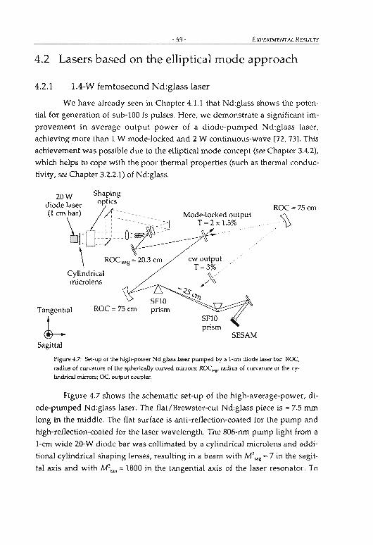
- 69- EXPERiMENTAL RESULTS
4.2 Lasers based on the elliptical mode approach
4.2.1 1.4-W femtosecond Nd:glass laser
We have already seen in Chapter 4.1.1 that Nd:glass shows the poten
tial for generation of sub-lOO fs pulses. Here, we demonstrate a significant im
provement in average output power of a diode-pumped Nd:glass laser,
achieving more than 1 W mode-locked and 2 W continuous-wave [72, 73]. This
achievement was possible due to the elliptical mode concept (see Chapter 3.4.2),
which helps to cope with the poor thermal properties (such as thermal conduc
tivity, see Chapter 3.2.2.1) of Nd:glass.
ROC=75cm
%
prismSESAM
Mode-Iocked outputT = 2 X 1.5%
cw outputT=3% ....
~)~ ..
'<>$%
ROC= 75 cm
20 W Shaping
diode laser ~OPhCS(1 cm bar) L ----- _
\ - --lr~O-~---_-~~~~~1~- --y---
\ ROC sag = 20.3 cm
CyLindricalmicrolens
Tangential
Jr--Sagittal
Figure 4.7: Set-up of the high-power Nd:glass laser pumped by a l-cm diode laser bar. ROC,
radius of curvature of the spherically curved mierors; ROCM " radius of curvature of the cy
lindrical mierors; oe, oUlput coupler.
Figure 4.7 shows the schematic set-up of the high-average-power, di
ode-pumped Nd:glass laser. The flat/Brewster-cut Nd:glass piece is = 7.5 mrn
long in the middle. The flat surface is anti-reflection-coated for the pump and
high-reflection-coated for the laser wavelength. The 806-nm pump light from a
I-ern wide 2D-W diode bar was collimated by a cylindrical microiens and addi
tional cylindrical shaping lenses, resulting in a beam with M2sag '" 7 in the sagit
tal axis and with M',an '" 1800 in the tangential axis of the laser resonator. To

prevent stress fracture, the output oE the single 20-W laser diode was split in
two beams and applied from opposite sides to the Nd:glass gain medium (see
Figure 4.7). The focused spot radius was approximately 120 J.1m x 1100 J.1ID with
a confocal parameter at least as long as the absorption length of 5.8 mm in the
1 % Nd-doped LG 760 glass (Schott laser glass [67]). We achieved an improved
heat removal from the glass medium in the sagittal direction by reducing the
thickness of the glass to 0.8 mm and by actively cooling only the upper and
lower side of the laser glass (see Figure 4.8). Aperture losses due to the thin me
dium were negligible.
CHAPTER4 - 70-
We have matched the laser mode to the highly elliptical pump mode
using a cylindrical cavity mirror next to the crystal. In order to reduce thermal
aberrations, which strongly affect the beam quality of the laser beam, we also
have made the tangential laser mode radius inside the gain medium (= 0.7 mm)
somewhat smaller than the pump beam radius (= 1.1 mm) (see Figure 4.8 and
Chapter 3.3.4). This overpurnping leads to an improved beam quality with a
measured M 2 = 1.2 for both axes, even at maximum output power. Higher
transverse modes in the tangential direction have been suppressed by the
stronger mean thermallens, which actually makes the cavity unstable for these
modes according to our simulations. We obtained a cw output power as high as2 W with a slope efficiency of 26 %.
Nd:glassLG 760 1%
TS~ L.-__""""7'<:.....j---''-l...L..w..~.,.-- ---l<'-
Pumpbeam
Figure 4.8: Laser and pump modes and the calculated temperature profiles (Le., T.." and
TM') at the f1at end o( the Nd:glass.
For femtosecond pulse generation, we modified the cavity by inserting
an SFI0 prism pair and aSESAM as the end mirror (see Figure 4.7). The meas
ured nonlinear reflectivity of the SESAM showed a maximum modulation
depth of 1.3 % and nonsaturable losses of 1 %. We focused the intracavity beam
onto the SESAM with a cylindrical mirrar to prevent a spectral flip in the tan-

- 71- EXPERIMENTAL RESULTS
gential plane. A spherical focusing mirror would reflect the longer wavelength
into th path of the shorter wavelength. The spot size radius on the SESAM was
calculated to be approximately 320 pm x 120 pm using standard ABCD-matrix
calcula ·ons. Thus, the pulse energy density incident on the SESAM was
233 pJ/ m2 (for 1 W output power), which corresponds to approximately 2
times the saturation fluence of 120 pJ/cm2 of the device. We obtained nearly
bandwidth-limited soliton pulses of 275 fs duration with 1.4 W average output
power and =61 kW peak power (see Figure 4.9). A similar result with 175 fs
pulse duration and 1.0 W of average power (= 43 kW of peak power) in two
output beams has previously been published (72).
Although the peak power of these Nd:glass lasers is quite respectable,
this concept can not compete in terms of average output power with the thin
disk approach as applied to Yb:YAG (see Chapter 4.3). Still, we have demon
strated th.at power levels comparable to those from Ti:sapphire lasers are possi
ble. For even higher average powers (> 10 W) with pulse durations far below
1 ps, one will probably rely on the development of new laser materials such as
Yb:KGW (see Chapter 3.2.1.2) with broad amplification bandwidth, large laser
cross-sections and good thermal properties.
-0.5 0.0 0.5
Time Delay, (ps)
(a)
1.045 1.050 1.055 1.060
Wavelength, (pm)
(b)
Figure 4.9: lntensity autocorrelation !rare (a) and corresponding optical spectrurn (b) 01275
15 pulses at a total output power 011.4 W. Dolled curve: Fit assuming an ideal sech' pulseshape.

CHAPTER 4 - 72 -
4.2.2 8-W picosecond Yb:YAG laser
Encouraged by the good results obtained with the high-power Nd:glass laser
we have also buHt an Yb:YAG laser based on the elliptical mode approach.
Yb:YAG (see Chapter 3.2.1.1) is a very promising gain medium for short-pulse
generation in the high-power regime. It shows a very good thermal conductiv
ity and a small quantum defect, which makes it potentially very efficient. Prob
lems arise from the quasi-three-Ievel nature, which leads to a high laser thresh
old. This threshold significantly rises with crystal temperature. Therefore, it is
crucial to have an efficient cooling as provided e.g. by the elliptical mode ap
proach.
Yb:YAG3%
W~'c:1i I~mPump bean: 2.7 mm 'iaser mode
Sagittal
.EJ:OJ~40_W
;1:Xw.~l*,*~: diode
' ~ bars
Pumpoptics
Flat foldingmirror
P. ~fi",,,,~li IMod<-lod"" """"''''~ I
!
~~ROC = 200 an i GTI
Figure 4.10: Set-up of the high-power Yb:YAG Iaser pumped by !wo polarization-eoupled
4O-W diode bars. ROC, radius of curvature of the spherically curved mirrors; ROC y •• radius
of curvatu.re of the cylindrical mirror; SESAM, semiconductor saturable absorber mirror;
HR, highly reflecting mirror; OC. output coupler; GTI, Gines-Tournois interferometer.
Figure 4.10 shows a schematic of the laser set-up. The Yb:YAG crystal is
pumped by two polarization-coupled 40-W diode bars at 940 nm (DILAS Di
odenlaser GmbH, Germany). Each diode has a cylindrical microiens attached to
the output face, forming a nearly collimated beam in the sagittal direction. Two
more cylindricallenses for each diode are used to further collimate the sagittal

-73- EXPERlMEI'ffAL RESULTS
direction as weH as to collimate the tangential direction of the beam. After po
larization-coupling the two beams with a thin-film polarizer (TFP), we use a
pair of two elosely spaced spherical doublets for focusing into the crystal, re
sulting in a beam with 1vfsag =10 in the sagittal direction and with 1vf!an =2800 in
the tangential direction. The focused pump spot radius is 1.36 mm x 0.10 mm.
We obtained a maximum pump power of 53 W at the location of the laser crys
tal and a pump intensity of =12 kW Icm2, to be compared with the intensity of
1.4 kWI cm2 for transparency at 1.03 }.lIIl (see Table 3.2).
The Yb:YAG crystal is flat/Brewster-cut and has 3 at. % Yb-doping, re
sulting in an absorption length of = 3 mm at the pump wavelength of 940 nm.
The flat surface is anti-reflection-coated for the pump wavelength and coated
for high reflectivity at the laser wavelength. For efficient heat removal, we
chose the thickness of the Yb:YAG crystal to be only 1 mm. The crystal is
mounted between two copper heat sinks, which are attached to thermo-electric
coolers. Due to the chosen pump and cooling geometry, the heat flow is nearly
one-dimensional, which reduces the effects of thermal lensing and stress
induced birefringence (see Chapter 3.4.2).
At multi-watt power levels, thermal effects are strang (mainly due to
the high laser threshold) despite of the smaH quantum defect of Yb:YAG and
the cooling geometry used. Trus can make the alignment of such lasers very dif
ficult, particularly because the alignment towards higher output power often
leads to local maxima with significantly lower power than in the global opti
mum, which is difficult to find. As already discussed in Chapter 3.5, a standing
wave laser cavity (with the gain medium not being located very elose to one
end of the cavity) has two stability zones, where zone I is substantially less sen
sitive to misalignment. Only by operating our laser in zone I, we have been able
to achieve the results mentioned below.
The used MOCVD-grown SESAM consists of a 15 nm truck lrlo.25Ga".7SAs
quantum weH embedded in an anti-resonant Fabry-Perat cavity, formed by a
GaAsl AIAs Bragg mirror with 25 layer pairs, a 70 nm AIAs spacer layer, a
70 nm GaAs spacer layer and a dielectric top reflector with = 70 % reflectivity.
The device has a modulation depth of = 0.15 %, a saturation fluence of
= 400 jlJ/cm2, and a recovery time of = 60 ps.

CHAPTER4
? r-----.,..-------,
~
~ 4 ~ 0 2 4 6
Delay time, (ps)
(a)
- 74-
1030 1031
Wavelength, (nm)
(b)
Figure 4.11: !ntensity autocorrelation trace (a) and optical spectrum (b) of the 2.2-ps pulses
obtained from the soliton mode-Iocked Yb:YAG laser. The total average output power (in
!wo beams) is 8.1 W. Dotted curves: Fils assuming an ideal sech' pulse and spectrum shape.
In order to suppress Q-switched mode locking instabilities (see Chap
ter 3.6) we operated the laser in the soliton mode locking regime (see Chap
ter 2.1), generating negative dispersion with a Gires-Toumois interferometer
[100] (GTI) in the cavity. We obtained pulses as short as 2.2 ps (see Figure 4.11)
with an average output power of 8.1 Wand a pulse repetition rate of 63 MHz
[79]. The laser output was split into two nearly diffraction-limited beams
(M2< 1.2 in sagittal and tangential direction), each with = 4 W average power
and = 29 kW peak power. A single output beam with the full power could be
generated using a GTI with smaller dispersion, used as a folding mirror, so that
the output coupler would be the end mirror. The obtained 2.2-ps pulses were
almost transform-limited (time-bandwidth product 0.34). Even shorter pulses
should be achievable using a GTI with broader bandwidth. A similar laser with
a single 40-W diode bar and a prism pair instead of the GTI generated 1.0-ps
pulses in a single output beam with 3.5 W average power and as much as
74 kW peak power.

-75 - EXPERiMENTAL RESULTS
4.3 Lasers based on the thin-disk concept
4.3.1 16-W sub-picosecond Yb:YAG thin disk laser
Although the average output power of the Yb:YAG laser from Chapter 4.2.2 is
quite respectable, the elliptical pump approach used there can not compete
with the thin-disk approach in terms of average output power. As already dis
cussed in Chapter 3.4.3, the thin-disk concept has the very significant advantage
of power scalability: Starting with an initial design, we can double the output
power by doubling the pump power and the mode area in the gain medium.
Owing to the unchanged intensity and the one-dimensional heat flow, the tem
perature in the disk will not increase, if the cooling system is capable of re
moving the waste heat. Therefore, the efficiency of the laser should not be de
creased even at high output power. In addition, the scaling procedure does not
make thermal problems more severe: The stability range of a laser cavity with
doubled mode size is reduced by a factor of 4 (see Chapter 3.5), but the focusing
power of the thermallens is reduced by the same factor. This can be seen by the
following consideration: For a thin thermallens with a given radially varying
phase difference L1cp(r) an approximate expression for the focallength f(r) can be
derived from simple geometrical considerations (see Figure 4.12):
Thermal lens
f(r)
Wavefronts
Fi~ure 4.12: Radial variation in focaJ length for an aberraled thermallens.
The re~u1ting expression is then given by
21Crj(r) ~ d(IHp(r»
A,----'-----'--'--=dr
(4.3)

CHAPTER4 -76-
(From Equation (4.3) it can be seen that, if the phase difference L1lp(r) shows a
parabolic dependence from r,j(r) is constant and the lens has no phase aberra
tion.) For laser materials such as Yb:YAG, the major contribution to thermal
lensing arises from the temperature dependence of the refractive index, while
the stress dependence of the refractive index and end-face bulging result in only
relatively weak additional contributions to lensing. Under this condition and by
assuming a parabolic temperature profile inside the gain medium, the phase
difference L1lp(r) will also show a parabolic dependence. Therefore, by doubling
the mode size, the first derivative of the phase difference L1lp(r) (at a given r) will
decrease by a factor of 4, leading to an increase of the focallength of the thermal
lens by the same value (see Equation (4.3)).
The used thin disk laser head (see Figure 3.10) consists of a 220~ thin
Yb:YAG disk, used as gain medium, which is mounted with one face on a heat
sink. This allows applying quite high pump power densities to the disko The
cooled face of the disk is coated for high reflectivity for the laser and pump
wavelengths, while the other side has an anti-reflection coating. As the diame
ter of the pump beam (= 1.2 mm) is larger than the thickness of the disk
(= 220 pm), the heat flux is nearly one-dimensional and directed along the opti
cal axis of the laser mode. This leads to a nearly homogeneous temperature pro
file within the pumped region in radial direction and thus to only weak thermal
lensing and low stress-induced birefringence. An optical arrangement consist
ing of a parabolic mirror and three roof prisms is used to obtain 16 passes of the
pump radiation through the thin disk [101]. This allows obtaining efficient
pump absorption despite the small absorption per double pass through the thin
disko A consequence of this is that the pump intensity is approximately constant
along the beam axis. The thin disk laser head is pumped by two fiber-coupled
30 W diode bars at =940 nm. The disk is slightly wedged to eliminate residual
reflections, which might disturb the mode locking process. In a simple cw cav
ity, the laser head generated 20 W near room temperature in a nearly diffrac
tion-limited beam. This output power is lower than obtained from similar lasers
without wedge, where = 30 W have been achieved with the same pump power.
The reason for Htis is probably related to strain ir1 the wedged disk and will be
investigated further. The focal length of the thermal lens of the thin disk at
maximum pump power was estimated to be about -1 m. The negative focusing

- 77- EXPERIMENTAL RESULTS
power can be explained with bending of the disk as a result of thermal expan
sion [102, 103].
As we have already seen in Chapter 3.4.3, spatial hole burning (SHB)
[86] un voidably occurs due to the geometry of the thin disk laser head. This
has a strong effect on the mode locking performance because it leads to inho
mogeneous gain saturation. In cw operation of our laser, SHB leads to laser os
cillation on severallines simultaneously, separated by as much as 0.7 nm due to
the small thickness of the Yb:YAG disk (220 ~). When we initially set the in
tracavity dispersion for the generation of pulses with several picoseconds, we
observed two (or even more) mode-locked pulses circulating in the cavity with
slightly different center wavelengths, corresponding to the different lines ob
served in cw operation. The reason for this is that the bandwidth of a single
pulse is not sufficient to saturate the whole gain. This regime sufters from a lack
of stability of pulse energies and timing. However, by reducing the negative
intracavity dispersion, we obtained mode locking with a single pulse in the
cavity. This lead to a pulse duration of =0.7 ps and an increased optical band
width of 1.5 nm, broad enough to largely "wipe out" the standing-wave pattern.
In this regime, SHB is even beneficial because it effectively flattens the gain
spectrum and thus allows for reduced pulse duration.
As a consequence of SHB, which inevitably occurs in thin disk lasers,
we have obtained stable mode locking only in a narrow range of pulse dura
tions around 0.7 ps (see Ref. [54]). Recently, we have developed a theoretical
model that can quantitatively describe these effects, and we have also proposed
a novel scheme to weaken the effect of SHB by using a special laser cavity [86].
In this cavity, the laser beam hits the thin disk under two different angles, cor
responding to two different periods of the standing-wave pattern. If the angles
are properly chosen, the pattern is largely wiped out. But even then, as our
model [86] predicts, the SHB effect is not totally eliminated. With an additional
etalon in the cavity (where the free spectral range is chosen appropriately (see
Ref. [86])), a much wider range of pulse durations is predicted, beginning at a
few picoseconds. The upper limit for the pulse duration is in this case not de
termined by SHB but by other factors such as the recovery time of the SESAM
and the very weak soliton effects at long pulse durations. Recently, we have
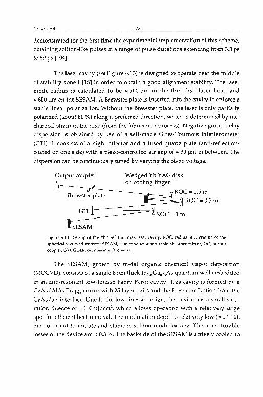
CHAPTER4 - 78-
demonstrated for the first time the experimental implementation of this scheme,
obtaining soliton-Iike pulses in a range of pulse durations extending from 3.3 ps
to 89 ps [\04].
The laser cavity (see Figure 4.13) is designed to operate near the middle
of stability zone I [36] in order to obtain a good alignment stability. The laser
mode radius is calculated to be = 500 Ilm in the tDin disk laser head and
=600 J.1m on the SESAM. A Brewster plate is inserted into the cavity to enforce a
stable linear polarization. Without the Brewster plate, the laser is only partially
polarized (about 80 %) along a preferred direction, which is determined by me
chanical strain in the disk (from the fabrication process). Negative group delay
dispersion is obtained by use of a self-made Gires-Tournois interferometer
(GTI). It consists of a high reflector and a fused quartz plate (anti-reflection
coated on one side) with a piezo-controlled air gap of =30 J.1ffi in between. The
dispersion can be continuously tuned by varying the piezo voltage.
Output coupler
Brewster plate
SESAM
Wedged Yb:YAG diskon cooling finger
Figure 4.13: Set-up of the Yb:YAG !hin disk laser cavity. ROC, radius of curvature of the
sphericalJy curved mirrors; SESAM, semiconductor saturable absorber mirror; oe, output
coupler; GTI, Gires-Toumois interferometer.
The SESAM, grown by metal organic chemical vapor deposition
(MOCVD), consists of a single 8 nm thick Inou;Gao.7.As quantum weil embedded
in an anti-resonant low-finesse Fabry-Perot cavity. This cavity is formed by a
GaAs/AlAs Bragg mirror with 25 layer pairs and the Fresnel reflection from the
GaAs/air interface. Due to the low-finesse design, the device has a small satu
ration fluence of = 100 IlJ/cm2, which allows operation with a relatively large
spot for efficient heat removal. The modulation depth is relatively low (= 0.5 %),
but sufficient to initiate and stabilize soliton mode locking. The nonsaturable
losses of the device are < 0.3 %. The backside of the SESAM is actively cooled to

- 79- EXPERIMENTAL RESULTS
'" 20 oe. At full power, we operate the SESAM at only '" 7 times the saturation
fluence. In this regime, we observed no signs of damage, which typically occurs
at saturation parameters 5 > 100 (see Chapter 3.7).
With the cavity shown in Figure 4.13 and an output coupler with 5.5 %
transmission at 1030 nm, we obtain a mode-locked average output power of
16.2 W for a maximum pump power of 57.5 W. To our knowledge, this is by far
the highest reported average output power for a femtosecond laser. The pulse
duration is 730 fs (see Figure 4.14), as expected for soliton pulses if the disper
sion introduced by the CTI is about -3700 fs2 per round-trip. The repetition rate
is 34.6 MHz, which results in a pulse energy of 0.46 11J and a peak power of
560 kW. The pulses are almost transform-limited (time-bandwidth product:
0.32), and the beam quality is measured to be not far from the diffraction limit
(Nf < 1.5). For the optimized setting of the CTI voltage, the onset of QML insta
bilities could be suppressed down to average output powers of about 6 W,
which is in agreement with the theory presented in [90].
~ ~ ~ 0 1 2
Time delay, (ps)
(a)
3 1028 1030 1032
Wavelength, (nm)
(b)
Figure 4.14: Intensity autocorrelation trace (a) and optical spectrum (b) of the 73O-fs pulses
obtained from the soliton mode-Iocked Yb:YAG !hin disk laser at full output power of
16.2 W. Dotted curves: Fils assuming an ideal sech' pulse and spectrum shape.
With a longer cavity (repetition rate: 15 MHz) we obtained pulses as
short as 680 fs [54]. In this case, the laser output was split in two nearly diffrac
tion-limited beams (Nf < 1.2), each with 7.9 W average power and 680 kW peak
power. The pulse energy was 2x 0.53 11J.

CHAPTER4 - 80-
We emphasize that not only the thin disk laser head concept, but the
whole concept of the passively mode-locked thin disk laser is power-scalable.
For the laser head itself, we have explained this above. Moreover, as the mode
diameter on the SESAM is significantly larger than the thickness of the sub
strate (450 ~), further power scaling (by increasing the mode area also on the
SESAM) will not significantly increase the temperature rise on the SESAM (see
Chapter 3.7). Finally, the tendency for Q-switched mode locking (see Chap
ter 3.6) or for thermal or non-thermal SESAM damage (see Chapter 3.7) will not
be increased. (This relies on the fact that the ratio of intracavity average power
and mode area on the thin disk laser head is kept constant.) Therefore, we ex
pect that our concept will allow passive mode locking of thin disk lasers with
even significantly higher powers, as long as near diffraction-limited perform
ance is possible (as demonstrated already for '" 100 W average power [83]). This
demonstrates very c1early that SESAMs are suitable for lasers with very high
powers, provided that suitable laser heads and SESAM designs are used.
Due to the high peak powers, the thin disk laser is a perfect tool for
nonlinear frequency conversion experiments. In Chapter 5, we will demonstrate
some preliminary results obtained with the thin disk laser as pump source for
such experiments.

Chapter 5
Extending to Other Wavelengths
5.1 IntroductionIn the last few years, there has been a growing interest in laser projection sys
tems. In this fjeld of image production with lasers, research and development
are confronted with the task of simultaneously providing three wavelengths
with consistently high laser output in the visible range. In order to illuminate
e.g. a cinema screen, laser display technicians would like to have about 10 W of
each wavelength. In the red wavelength area, direct-emitting laser diodes are
already available as laboratory test sampies. However, in terms of the green
and blue wavelength regime, no high-power diodes are available so far. There
fore, these colors have to be generated by frequency mixing, e.g. by means of
optical pararnetric oscillators (OPOs).
There are many different schemes proposed to generate red, green and
blue wavelengths. Recently, a system has been presented that generates 7.1 W
at 629 nm, 6.9 W at 532 nm, and 5 W at 446 nm [105). This laser system is based
on a passively mode-Iocked Nd:YVO. laser oscillator emitting at 1.064 11m, an
arnplifier system to boost the output of the oscillator, and a KTA-OPO. In a first
step, part of the =1 11m output of the pump laser is converted by means of a
nonJinear crystal (LBO) to reach the green (532 nm) wavelength regime (second
harmonie generation). The rest of the 1.064-pm output is used to pump an OPO
emitting at 1.535 11m (signal wavelength) and at 3.468 11m (idler wavelength).
- 81 -

CHAPTERS - 82-
The red 629-nm light is then generated by sum-frequency mixirg of the OPO
signal wave and the 1.064 ~m pump in a KTA crystal. Finally, tre blue 446-nm
light is provided by a sum-frequency mixing process that mixesthe generated
red light with the residual OPO signal wave in a LBO crysta1.
With the mode-Iocked thin disk laser presented in Ch<pter 4.3.1, we
have now a perfect tool to develop a much simpler system forlaser displays
than described above. This is mainly due to the fact that our syitem does not
rely on an amplifier chain (which makes the whole set-up rathe' complex). In
the following, we will discuss preliminary results obtained fromnonlinear fre
quency experiments. In these experiments, we mainly concentratld on the gen
eration of l.5-~m light. With a special scheme as e.g. described ablve, one could
convert this wavelength in a next step to the desired wavelength(E).
5.2 Seeond harmonie generationIn a first step, we tried to frequency-double the 1.03-~m output cf the thin disk
laser (see Chapter 4.3.1). The high peak power of the laser allowe( using critical
phase matching at room temperature, while efficient conversiOl with signifi
cantly longer pulses would have required non-critical phase rratching in an
oven at elevated temperatures. The 13.8 W of incident fundameüal light was
focused to a beam radius of = 60 ~m in an externalS mm long mti-reflection
coated LiB30 S (LBO) crystal. With Ws set-up, we achieved up to 8W of average
output power at 515 nm in a single pass, corresponding to a cmversion effi
ciency of 58 %.
5.3 Optieal parametric generationOptical parametrie generation (OPG) in a single pass through ;:(2) nonlinear
crystal is a simple way to generate ultrashort pulses that are tuna:>le in a broad
wavelength range. In contrast to typical ultra fast optical parameric oscillators
(for an exception, see Chapter 5.4), OPG does not require an os:illator cavity
that is synchronized to the pump laser. However, the required punp intensities

I HWP PBS
Variable attenuator,-------,
- 83 - EXTENDING Ta OTHER WAVELENGTHS
are much higher. For this reason, so Ear aPG experiments with ultrashort pulses
have alwa s required amplified pump sources, e.g. based on a mode-locked os
cillator and a high-gain amplifier opera ted at a repetition rate oE typically Ear
below 1 MHz [106, 107]. Such pump sources lead to quite complex systems, and
low repetition rates very much limit the obtainable average output power. By
using the thin disk laser presented in Chapter 4.3.1, we have been able to dem
onstrate a parametric generator that is directly pumped with a mode-locked la
ser, not using any amplifier system. In this way, we have obtained up to 0.5 W
oE average power in Eemtosecond pulses at 35 MHz repetition rate in the wave
length range oE 1.38 - 1.56 pm using a periodically poled LiNba3 (PPLN) crystal
[108]. The corresponding range oE the idler is 3.03 - 4.06 pm.
PPLN is attractive Eor aPG experiments because oE its high effective
nonlinearity (dorf = 17 pm/V) and the possibility to control the phase-matching
wavelengths with the period oE the poling pattern. The used PPLN crystal was
produced by electric field poling [109]. It contains 10 periodically poled chan
nels with various poling periods between 27.1 pm and 30.4 pm. Switching be
tween the channels (by moving the crystal) allows to address different ranges oE
signal wavelengths. For a given channel, temperature tuning allows to cover a
continuous range oE several nanometers. These are overlapping, so that in total
we can cover a very large wavelength range. The temporal walk-off within the
7-mm crystallength is in the order oE the pulse duration oE our laser.
Y1::YAGthindisk laser h-II--L/f----r-~---____7I\ HR 1030 nm(346 MHz)
Pump wave @ 1030 nm( < 15 W, 730 Es )
Reflecte:lsi~~I_~,:,~
Signal wave1.38-1.56 11m
Figur. 5.J: Set-up of the single-pass optical parametrie generation (OPG) experiment. The
pumpbearn is sent through a variable attenuator (HWP, half wave plate; PBS, polarizing
beamsplitter) and then focused into the uncoated PPLN crystal. The crystal was operated
above 150 'e to avoid photorefractive damage. The signal wave is separated by dichIOic
mirros.

CHAPTER5 - 84-
The OUtput beam of the Yb:YAG thin disk laser (see Chapter 4.3.1) was
first sent through a variable attenuator, eonsisting of a Ä./2 plate and a pclariz
ing eube (see Figure 5.1). Then, it was focused with a mirror of 300-mm :adius of
curvature to a spot with 6O-pm radius in the PPLN crysta1. The pump beam was
slightly tilted with respect to the normal end faces of the erystal in order to pre-
vent refleetions from disturbing the laser. Seme Q-switehing tendency of the
laser was nevertheless observed beeause the magnitude of the tilt was limited
by the small width of the poled ehannels (0.5 rnm).
Most of the aPG output power appeared behind the PPLN erystal,
while the refleetions at the uneoated crystal end face caused some part of the
power to be emitted in backward direction and transmitted through the focus
ing mirror. The signal output power (between 1.38 pm and 1.56 pm) was meas
ured with a thermal power meter after eliminating the other wavelength eom
ponents with a set of dichroic mirrors. The different poled channels allowed to
generate between 0.1 W and 0.5 W of signal output power (in forward direction
only) for a pump power of ~ 10 W ineident on the erystal. For a signal beam at
A. = 1.5 pm, the M2 value was 2.8 in sagittal and 2.0 in tangential direetion. At
high pump powers, we observed saturation or even a drop of the signal output
power, depending on the used channe\, accompanied by a signifieantly deterio-
rated beam quality. Some channels have been operated with output powers of
~ 0.2 - 0.3 W for several hours until the onset of damage (beam distortions and
redueed output power) was observed. The idler power could not be measured
but is expected to be up to 0.25 W in the range from 3.03 pm to 4.06 pm2l• We
also observed up to ~ 0.1 W of green light around 515 nm (second harmonie of
the pump beam), in addition to not quantified power levels at the second har
monie of the signal wave and in the UV around 343 nm (third harmonie of
pumpbeam).
The erystal was opera ted in an oven at a temperature T> 150°C to
avoid photorefractive damage. For different erystal temperatures in the range
from 150°C to 250°C and grating periods from 27.1 pm to 29.2 pm, we obtained
signal wavelengths horn 1.38 pm to 1.56 pm. The spectrum was broader for
21 It has to be noted that the atmospheric transmission strongly varies in the wavelength reginne between2.8 \.Iffi and 3.9 \.Iffi (see •.g. Re!. [110]).

- 85 - EXTENDING Ta OTHER WAVELENGTHS
Honger grating periods (from 10 nm FWHM for a grating period of 27.1~ and
ia signan wavelength at 1.377 11m, up to 40 nm for a grating period of 29.2 ~
iand a s;ignal wavelength of 1.55 11m), as could be expected from the broader
!phase matching bandwidth at given temperature for longer grating periods.
~
;i~ ~
;ic' ~0
'.0 Ei''"Qj ;:l.... !:J....0 uU <ll
.9 P-.Cf)
;:l
<t:-{).4 0.0 0.4 1400 1440 1480 1520
Delay time, (ps) Wavelength, (nm)
~
;i~ ~
;ic' ~0
'.0~''"Qj
t:0 u
B<llP-.
Cf);:l
<t:-{).4 0.0 0.4 1400 1440 1480 1520
Delay time, (ps) Wavelength, (nm)
(a) (b)
Figure 5.2: intensity autocorrelalion Irace (a) and oplical speclrum (b) of the signal wave for
signal powers of 150 mW and 500 mW (for 28.4 J.llIl graling period). The FWHM pulse dura
lion was determined from the autocorrelalion trace assuming a sech' pulse shape (dottedcurve: fitting funclion). The pulse duralion is 207 fs for 150-mW output power and ~ 270 fs
forSOOmW.
The duration of the signal pulses was measured by intensity autocor
relation assuming an ideal sech2 pulse shape. For 28.4 11m grating period,
1.46~ signal wavelength and 150 mW output power, we obtained a (decon
volved) FWHM pulse duration of 207 fs (z 3 times shorter than the 0.73 ps
pump pulses), a spectral width of 21 nm (FWHM), and a time-bandwidth
product of z 0.6 (see Figure 5.2). This shows that the pulses are not far from the

CHAPTERS - 86-
transform limit ('" 0.315 for ideal sech2 pulse shape). At 0.5 W, we obtained a
spectral width of 28 nm and a pulse duration of 270 fs, leading to a time
bandwidth product of '" 1.1.
5.4 Optical parametric oscillationSynchronously pumped optical parametric osdllators (OPas) are interesting
sources of broadly wavelength-tunable ultrashort pulses as required for many
applications. Recently, we have shown that the combination of a thin disk laser
as pump source with a fiber-feedback opa results in a system with a number of
very attractive features [111]. The mentioned fiber-feedback opa is a novel
type of synchronously-pumped oPa, where a single-mode fiber represents
most of the cavity length (see Figure 5.3).
Our concept has lead to a very stable and compact opa set-up, which is
unusually insensitive against intracavity losses and drifts of the opa cavity
length. Even with non-optimized optical components' we obtained up to 2.7 W
of average power in 900-fs pulses around 1.45 J.lIn [111]. In contrast to many
other oPas in this pulse duration regime, the fiber-feedback opa does not
need an active stabilization of the cavity length.
The incorporation of a fiber into a cavity containing bulk components
in general will introduce substantiallosses, mainly at the fiber launch. Never
theless, a high power conversion effidency can be achieved if a large parametrie
gain is available and most of the power of the resonant wave is coupled out di
rectly after the nonlinear crystal. Other intracavity losses then affect only a
small portion of the generated power. We achieved a small-signal gain in the
order of 90 dB by applying a high average pump power of up to 8.2 W to a pe
riodically poled LiTa03 (PPLT) crystal, which has a relatively high nonlinear
i~ ( d.ff '" 9 pm/V; see Ref. [112]). The Yb:YAG thin disk pump laser is slightly
modified from the one described in Chapter 4.3.1, generating pulses with a du-
22 Please note thal the nonlinearity of PPLT is onJy aboul half of thai of the PPLN cryslal. Unfortunalely,we did nol have a PPLN crystaJ al our disposaJ al the time of these experimenls.

- 87 - EXTENDING Ta OTHER WAVELENGTHS
ration of 0.6 ps at a repetition rate of 35 MHz, and delivering up ta =11 W of
average power.
The pump beam is focused with a curved mirror (MI) to a waist with
90-pm radius in the middle of the PPLT crystal (see Figure 5.3). The 22-mm long,
uncoated crystal is operated at a temperature of =150 ·C to avoid photorefrac
tive damage. The OPO signal wavelength depends on the period of the poling
pattern and the crystal temperature. Our 0.5 mm thick crystal, fabricated by the
same procedure as described for periodic poling of lithium niobate [113], has 8
poled regions of transverse width 1.2 mm, with different grating periods of
28.3}1m - 29 J.lm, resulting in signal wavelengths between 1429 nm and 1473 nm
(for 150 ·C crystal temperature). After the nonlinear crystal, the signal wave is
collimated and separated from the pump and idler waves by a combination of 3
dichroic elements (mirrors M3 and M., filter). One of the two reflected beams
from an uncoated glass substrate is used for the signal feedback, while the
transmission of 82 % represents the signal output. The feedback light at
=1.45 pm is launched into a 4.6 m long standard telecom fiber, which is single
mode at the signal wavelength. The light emerging from the fiber is mode
matched by the lenses f, and f2 and fed back into the crystal through the di
chroic mirror M~ which is highly reflective for the pump wave and transmis
sive (70 %) at the signal wavelength.
UncoatedFilter glass
Signal wave
(2.3-2.7 W, 1.43-1.47 j./m)
Single-mode fjber (4.6 m length)
Figur. 5.3: Set-up of the OPO ring cavity. MI - M•• mirrors; fl - f" lenses; PPLT, crystal of
periodically poled tiTaO,.
The different gratings aIlow generation of signal power output between2.3 W and 2.7 W (measured with a thermal power meter) for a pump power of

CHAPTER5 - 88-
8.2 W incident on the crystal. Figure 5.4 shows the typical performane for one
grating. We would expect to obtain even higher signal output powersn the or
der of 4 W by reducing the losses of several non-optimized optical conponents
(filter: 5 %, glass substrate: one 9-% reflection suppressed, 15 % at unceted end
faces of the PPLT crystal). The internal pump depletion is up to = 80'/0 at full
power. If required, the idler power (expected to be 1.0-1.1 W in the pesent ex
periment) in the range 3425-3670 nm could be extracted through an otimized
mirror M).
3
0Trans. pump 10 dB
I •Trans. pump 0 • 0
• 0
~2~.
0 • 0
OCD oO 0 •• Q B
• o 0 0...' -. .- 0Q) 1/ • •• • • •~
.........0 •• 0 0
0.. .- 0 0• 0
• 0Signal-: 0 ~ Signal 10 dB
00 2 4 6 8
Pump power, (W)
Figure 5.4: Signal power (filled eircJes) and transmilted pump power (filled rectanglesver
sus ineidenl pump power for a signal wave of 1429 nm (grating period 28.3 ).Ull). Ope. cir
cles and reclangles: Same with a 1G-dB attenuator in the feedback loop.
A notable feature of the fiber-feedback oPa, which results rom the
high gain and strong output coupling, is the insensitivity of the perfomance to
cavity losses: The maximum output power is reduced by only 6 % ifan addi
tional filter with 10 dB loss at the signal wavelength is inserted at he fiber
launch between the glass substrate and lens f) (see Figure 5.3 and Fifure 5.4).
Obviously, it is not necessary to minimize the losses in the feedback hop after
the output coupling (lenses f,-f) were uncoated and the polarization 0 the sig
nallight emerging from the fiber was not controlled).
For a signal wavelength of 1429 nm and an output power of 1 \1, the M2
value was 1.2 in tangential and 1.3 in sagittal direction (the M 2 vahe of the
pump beam was 1.1). For 2.5 W signal power, the M2 value increasedto 2.5 in
tangential direction and 2.2 in sagittal direction. There might be a si;nificant

- 89 - EXTENDING Ta OTHER WAVELENGTHS
contribution to Ws beam quality degradation arising from thermally induced
bulging of various non-optimized substrates (mirrors M~ M, and the filter)
which are heated by idler absorption.
The duration of the signal pulses was measured by intensity autocor
relation. For all poled channels and pump powers, the pulse duration (FWHM)
is typically around 700-900 fs assuming an ideal sech2 pulse shape. The spectral
width is around 3 - 4 nm (FWHM), leading to a time-bandwidth product of
0.36 - 0.53. For 2.5 W signal power at 1429 nm (grating period 28.3 11m), we ob
tain 870-fs pulses with a spectral width of 2.8 run, leading to a time-bandwidth
product of 0.36 (see Figure 5.5), which is not far from the transform limit.
~ ~ 0 2
Delay time, (ps)
(a)
1420 1430 1440
Wavelength, (nm)
(b)
Figure 5.5: Intensity autocorrelation trace (a) and optical spectrum (b) 01 the signal wave
(1429 nm) with 2.5 W average power. The FWHM pulse duration 01 870ls was determined
by assuming a sech' pulse shape (dolted curve: Htting funclion). The time-bandwidth prod
uct is 0.36.
Despite the short pulse duration, the adjustment of the fiber-feedback
OPO cavi:y length is not critical because of the high parametric gain. For exam
pie, even if only the leading edge of a signal pulse is temporally overlapped
with the pump pulse in the crystal, the high parametric gain still allows for effi
cient energy extraction (see Ref. [111]). Also note that nonlinear effects in the fi
ber can Ifad to a substantial temporal broadening of the seed pulses. The op
eration of the fiber-feedback OPO system is stable over hours, and no signs of
crystal damage were observed during all experiments.

CHAPTER5 -90-
Note that the signal pulse energy in the fiber is about two orders of
magnitude higher than the soliton energy. Therefore, we expect the temporal
and spectral shape of the pulses after the fiber to be significantly distorted.
Nevertheless, we obtained near bandwidth-limited output signal pulses be
cause the short pump pulses create only a narrow time window for gain and
the output spectral width is limited by the phase-matching bandwidth.

Chapter 6
Conclusion and Outlook
In this thesis, we have described ways towards diode-pumped passively mode
locked lasers with high average powers and discussed the main challenges to be
met on this route. In particular, we have shown that the performance of a high
power laser critically depends on the pump and cavity design, as it directly in
fluences the magnitude of thermal effects and the sensitivity against them. In
addition, we have demonstrated that the strong tendency of femtosecond lasers
towards Q-switched mode locking requires a careful optimization of such la
sers. An important finding is that semiconductor saturable absorber mirrors
(SESAMs) are suitable for operation at very high average power levels, pro
vided that certain design guidelines (which not only involve properties of the
saturable absorber but also of the laser head) are taken into account. Therefore,
SESAMs will remain the first choice even for lasers with much higher average
output powers than demonstrated so far.
We have used different broadband gain media and pump approaches
to find the most promising solution for a diode-pumped femtosecond high
power laser. These lasers strongly depend on the development and improve
ment of high-power laser diodes. Whereas high-brightness laser diodes are so
far restricted to power levels in the watt regime (due to catastrophic optical
damage, see e.g. Ref. [43]),60 W and even more are commercially available from
low-brightness laser diodes. The characteristics of these laser diodes directly
influence the choke of the pump set-up (together with the choke of the laser
gain medium). In this thesis, three different pump geometries have been tested
- 91-
with respect to their suitability as high-power pump sourees. By using high
brightness laser diodes in combination with the new laser material Yb:KGW
[57, 58], we have obtained average output powers of up to 1.1 W in pulses as
short as 176 fs duration. The corresponding peak power is 64 kW. These results
have become possible due to the favorable properties of Yb:KGW, which com
bines a good thermal conductivity with a relatively large emission cross-section
(see Chapter 3.2.1.2). The biggest advantage of this approach is the simplicity of
the pump set-up. However, this approach is restricted to the watt regime due to
the limited pump power available from high-brightness diodes so far. In addi
tion, this pumping scheme is not suitable for laser materials with a low thermal
conductivity (such as e.g. glass) because of the high pump intensities achieved
inside the gain medium, which can lead to thermal fracture ultimately. Such
media need a special pump approach. The eUiptical pump concept (see Chap
ter 3.4.2) helps to cope with the thermal problems of such gain media. This ap
proach makes use of the highly asymmetrie spatial profile of commercially
available high-power low-brightness laser diodes. Therefore, no special beam
shaper [80] (which symmetrizes the beam qualities in both directions of the di
ode) is required to generate a circular pump focus. Due to the highly elliptical
pump beam, very thin gain media (of only 1 mm thickness or less) can be used,
which allows for very efficient cooling from the top and bottom side (see Chap
ter 3.3.2), and therefore limits the maximum temperature rise. This is particu
larly beneficial for quasi-three level gain media such as Yb:YAG, which are less
efficient at elevated temperatures. In addition, this approach has the potential
to reach the ten-watt regime due to the availability of high-power laser diodes
of up to 60 Wand due to its scalability (see Chapter 3.4.2). However, in order to
minimize thermallensing and thermal aberration, one normally has to operate
the system with laser modes inside the gain medium that (in tangential direc
tion) are smaller than the pump beam (see Chapter 3.3.4), leading to a decrease
in efficiency of the whole laser system. The large laser mode in tangential di
rection also makes great demands on the cavity design (see Chapter 3.5). Nev
ertheless, we have demonstrated average output powers as high as 8.1 W (and
peak powers of up to 74 kW) in the picosecond and up to 1.4 W (with 61 kW
peak power) in the femtosecond regime by applying the highly elliptical pump
approach (see Chapters 4.2.1 and 4.2.2, respectively).
CHAPTER6 - 92-

- 93- CONCLUSION AND OUTLOOK
Although the peak and average powers obtained with the elliptical
pump approach are quite respectable, this concept can not compete with the
thin-disk approach in terms of average output power. So far, the thin-disk con
cept is the most promising approach towards the goal of diode-pumped high
power femtosecond lasers. The crucial advantage of this pumping scheme is its
power scalability (see Chapter 3.4.3). In the near future, this will allow for a
drastic increase in output power, without decreasing the efficiency, increasing
thermal problems or the tendency towards Q-switching instabilities. In a pre
liminary experiment, we have obtained average output powers of more than
16 W in pulses of 730 fs duration. The corresponding pulse energy and peak
power have been as high as 0.5 flJ and 0.56 MW, respectively. This is by far the
highest reported average output power for a femtosecond laser (status: Oetober
2000).
By applying the thin disk laser as pump, we were able to demonstrate
tunable high-power femtosecond sources in the wavelength regime around
1.5 flm, which is e.g. the wavelength regime of choice in telecommunications.
We have demonstrated the first optical parametrie generator (OPG) directly
pumped with a mode-locked laser at the full laser repetition rate. This OPG
scheme is significantly simpler than previous femtosecond parametrie genera
tors. We have obtained up to 0.5 W of average power in 270 fs pulses at 35 MHz
repetition rate in the signal wavelength range 1.38 - 1.56 flm. Up to 2.7 W (in
pulses as short as 700 fs) in the wavelength range trom 1429 nrn to 1473 nrn was
generated by demonstrating the first synchronously purnped optical parametrie
oscillator (OPa) with feedback through a singly-mode fiber. The big advantage
of this fiber-feedback opa is the very compact set-up, since most of the reso
nator feedback path consists of a standard telecom fiber. The high average
power, short pulse durations and broad tunability make these sources very in
teresting for applications e.g. in spectroscopy or in the field of laser projection.
The present thesis shows that diode-pumped femtosecond lasers are
now approaching a power regime where additional arnplification stages, which
usually rely on complicated multi-pass arrangements (especially in the femtG-

CHAPTER6 - 94-
second regime), are no longer needed23. Trus leads to compact high-powtr hser
sourees, which allow e.g. for very efficient wavelength conversion by sirgle
pass interactions with nonlinear crystals. In the near future, new high'pcwer
mode-Iock.ed lasers based on the thin-disk concept will reach the 100 W Iwel,
opening up new fields of laser applications such as e.g. laser projection.
" It has to be noted that the additional use of amplification stages can still lead to much high'" ou:putpowers.

References1. T. H. Maiman, "Stimulated optical radiation in ruby," Nature, vol. 187, pp. 493
494,1960.
2. R. J. Keyes, T. M. Quist, "1njection luminescent pumping of CaF2:U3+ with GaAsdiode lasers," AppI. Phys. Lett., vol. 4, pp. 50-52, 1964.
3. R. L. Byer, "Diode Laser-Pumped Solid-State Lasers," Seienee, vol. 239, pp. 742,1988.
4. A. E. Siegman, LAsers, University Science Books, Mill Valley, California, 1986.
5. D. E. Spence, P. N. Kean, W. Sibbett, "60-fsec pulse generation from a self-modelocked Ti:sapphire laser," Opt. Lett., vol. 16, pp. 42-44, 1991.
6. U. Keller, G. W. 'tHooft, W. H. Knox, J. E. Cunningham, "Femtosecond Pulsesfrom a Continuously Self-Starting Passively Mode-Locked Ti:Sapphire Laser,"Opt. Lett., vol. 16, pp. 1022-1024, 1991.
7. F. Salin, J. Squier, M. Piche, "Modelocking of Ti:Sapphire lasers and self-focusing:a Gaussian approximation," Opt. Lell., vol. 16, pp. 1674-1676, 1991.
8. D. H. Sulter, G. Steinmeyer, L. Gallmann, . Matuschek, F. Morier-Genoud,U. Keller, V. Scheuer, G. Angelow, T. Tschudi, "Semiconductor saturableabsorber mirror-assisted Kerr-lens mode-locked Ti:sapphire laser producingpulses in the two-cycle regime," Opt. Lell., vol. 24, pp. 631-633, 1999.
9. U. Morgner, F. X. Kärrner, S. H. Cho, Y. Chen, H. A. Haus, J. G. Fujimoto,E. P. Ippen, V. Scheuer, G. Angelow, T. Tschudi, "Sub-two-cycle pulses from aKerr-lens mode-Iocked Ti:sapphire laser," Opt. Lett., vol. 24, pp. 411-413,1999.
10. U. Keller, D. A. B. Miller, G. D. Boyd, T. H. Chiu, J. F. Ferguson, M. T. Asom,"Solid-state low-loss intracavity saturable absorber for d:YLF lasers: anantiresonant semiconductor Fabry-Perot saturable absorber," Opt. Lett., vol. 17,pp. 505-507, 1992.
11. U. Keller, K. J. Weingarten, F. X. Kärrner, D. Kopf, B. Braun, I. D. Jung, R. Fluck,e. Hönninger, N. Matuschek, J. Aus der Au, "Semiconductor saturable absorbermirrors (SESAMs) for femtosecond to nanosecond pulse generation in solid-statelasers;' IEEE J. SeIeet. Topies Quantum Eleetron., vol. 2, pp. 435-453, 1996.
12. U. Keller, "Semiconductor nonlinearities for solid-state laser modelocking and Qswitching," in Nonlinear Opties in Semieonduetors, Eds. : E. Garmire, A. Kost, Academic Press Inc., Boston, vol. 59, pp. 211-286, 1999.
-95 -

REFERENCES - 96-
13. A. Maksimchuk, S. Gu, K. Flippo, D. Umstadter, G. Mourou, "MeV proton beamdriven by a high-intensity laser," Conference on Lasers and Electro-Optics, Technical Digest Series 2000, paper CWG4, p. 271, 2000.
14. R. M. Verdaasdonk, "Medicallasers: fundamentals and applications," in Advancesin lasers and applications, Eds. : D. M. Finlayson, B. D. Sinclair, Scottish universitiessummer school in physics, institute of physics publishing, St. Andrews pp. 181226, 1999.
15. G. H. C. New, "Pulse evolution in mode-locked quasi-eontinuous lasers," IEEE J.Quantum Electron., vol. 10, pp. 115 - 124, 1974.
16. H. A. Haus, "Theory of Mode Lodung with a Slow Saturable Absorber," IEEE J.Quantum Electron., vol. 11, pp. 736-746, 1975.
17. H. A. Haus, "Theory of modelocking with a fast saturable absorber," J. Appl.Phys., vol. 46, pp. 3049-3058, 1975.
18. H. A. Haus, J. G. Fujimoto, E. P. Ippen, "Structures for additive pulse modelocking," J. Opt. Soc. Am. B, vol. 8, pp. 2068-2076, 1991.
19. F. X. Kärtner, I. D. Jung, U. Keller, "Soliton Modelocking with Saturable Absorbers," Special Issue on Ultra/ast Electronics, Photonics and Optoelectronics, IEEE J. Select. Topics Quantum Electron., vol. 2, pp. 540-556, 1996.
20. I. D. Jung, F. X. Kärtner, L. R. Brovelli, M. Kamp, U. Keller, "Experimental verification of soliton modelocking using only a slow saturable absorber," Opt. Lett.,vol. 20, pp. 1892-1894, 1995.
21. K. J. Blow, D. Wood, "Modelocked lasers with nonlinear extemal cavities," J. Opt.Soc. Am. B, vol. 5, pp. 629-632, 1988.
22. E. P. Ippen, H. A. Haus, L. Y. Liu, "Additive Pulse Modelocking," J. Opt. Soc. Am.B, vol. 6, pp. 1736-1745, 1989.
23. T. Brabec, C. Spielmann, P. F. Curley, F. Krausz, "Kerr lens modelocking," Opt.Lell., vol. 17, pp. 1292-1294, 1992.
24. M. Piche, F. Salin, "SeIf-mode locking of solid-state lasers without apertures,"Opt. Lell., vol. 18, pp. 1041-1043, 1993.
25. F. X. Kärtner, U. Keller, "Stabilization of soliton-like pulses with a slow saturableabsorber," Opt. Lell., vol. 20, pp. 16-18, 1995.
26. F. X. Kärtner, D. Kopf, U. Keller, "Solitary pulse stabilization and shortening inactively mode-locked lasers," J. Opt. Soc. Am. B, vol. 12, pp. 486-496, 1995.
27. F. X. Kärtner, J. Aus der Au, U. Keller, "Modelocking with slow and fast saturableabsorbers - What's the difference?," IEEE J. Select. Topics Quantum Electron., vol. 4,pp. 159-168,1998.
28. L. R. Brovelli, U. Keller, T. H. Chiu, "Design and Operation of AntiresonantFabry-Perot Saturable Sernicondudor Absorbers for Mode-Locked Solid-StateLasers," J. Opt. Soc. Am. B, vol. 12, pp. 311-322, 1995.

- 97- REFERENCES
29. R. L. Fork, O. E. Martinez, J. P. Gordon, "Negative dispersion using pairs ofprisrns," Opt. Lett., vol. 9, pp. 150-152, 1984.
30. D. Kopf, G. J. Spühler, K. J. Weingarten, U. Keller, "Mode-locked laser cavitieswith a single prism for dispersion compensation," Appl. Opt., vol. 35, pp. 912-915,1996.
31. J. P. Gordon, R. L. Fork, "Optical resonator with negative dispersion," Opt. Let/.,vol. 9, pp. 153-155, 1984.
32. M. Ramaswamy-Paye, J. G. Fujimoto, "Compact dispersion-compensating geometry for Kerr-lens mode-locked femtosecond lasers," Opt. Lett., vol. 19,pp. 1756-1758,1994.
33. R. Paschotta, J. Aus der Au, U. Keller, "Strongly enhanced negative dispersionfrom thermal lensing or other focusing effects in femtosecond laser cavities;' J.Opt. Soc. Am. 8, vol. 17, pp. 646-651, 2000.
34. O. E. Martinez, "Matrix Formalism for Pulse Compressors;' IEEE J. Quantum Electran., vol. 24, pp. 2530-2536, 1988.
35. O. E. Marlinez, "Matrix Formalism for Dispersive Laser Cavities;' IEEE J. Quantum Electron., vol. 25, pp. 296-300, 1989.
36. V. Magni, "Mullielement stable resonators containing a variable lens;' J. Opt. Soc.Am. A, vol. 4, pp. 1962-1969, 1987.
37. R. Paschotta, J. Aus der Au, U. Keller, "New scheme to strongly enhance thenegative group delay dispersion from Brewster interfaces;' Advanced Solid-StateLasers, Vol. XXVI of 1999 OSA Trends in Optics and Photonics, paper TuA5,pp. 372-374,1999.
38. E. C. Honea, R. J. Beach, S. C. MitchelI, J. A. Skidmore, M. A. Emanuel, S. B. Sutton, S. A. Payne, P. V. Avizonis, R. S. Monroe, D. G. Harris, "High-power dualrod Yb:YAG laser;' Opt. Let/., vol. 25, pp. 805-807, 2000.
39. K. Contag, S. Erhard, M. Karszewski, M. Larionov, D. Müller, C. Stewen, A. Giesen, I. Johannsen, "Power scalability and beam quality of the thin disk laser;'Conference on Lasers and Electro-Optics, Technical Digest Series 2000, paper CTuE3, p. 198,2000.
40. T. Beddard, W. Sibbett, D. T. Reid, J. Garduno-Mejia, N. Jamasbi, M. Mohebi,"High-average-power, 1-MW peak-power self-mode-locked Ti:sapphire oscillator;' Opt. Let/., vol. 24, pp. 163-165, 1999.
41. Z. Liu, S. Izumida, S. Ono, H. Ohtake, N. Sarukura, "High-repetition-rate, highaverage-power, mode-locked Ti:sapphire laser with an intracavity continuouswave amplification scheme;' Appl. Phys. Lett., vol. 74, pp. 3622-3623, 1999.
42. J. Jiang, T. Hasama, Z. Zhang, T. Sugaya, T. Nakagawa, "1.25-MW peak-powerKerr-lens mode-locked Ti:sapphire laser with a broadband semiconductor saturable-absorber mirror;' Opt. Commun., vol. 183, pp. 159-163,2000.

REFERENCES - 98-
43. P. Peuser, N. P. Schrnitt, Diodengepumpte Festkörperlaser, Eds. : G. Herziger,H. Weber, Springer-Verlag Berlin Heidelberg, Germany, 1995.
44. M. Stalder, M. Bass, B. H. T. Chai, ''Thermal quenching of fluorescence in chromium-doped fluoride laser crystals," J. Opt. Soc. Am. B, vol. 9, pp. 2271-2273,1992.
45. W. Koechner, Solid-State Laser Engineering, Eds. : A. L. Schawlow, A. E. Siegman,T. Tamir, H. K. V. Lotsch, Springer Series in Optical Sciences, Springer-VerlagBerlin Heidelberg, Germany, vol. 1, 1996.
46. Y.-F. Chen, "Design Criteria for Concentration Optimization in Scaling DiodeEnd-Pumped Lasers to High Powers: lnfluence of Thermal Fracture," IEEE J.Quantum Electron., vol. 35, pp. 234, 1999.
47. K. A. Cerqua, S. D. Jacobs, A. Lindquist, J. Non-Cryst. Solids, vol. 93, pp. 361, 1987.
48. E. C. Honea, R. J. Beach, S. B. Sutton, J. A. Speth, S. C. MitchelI, J. A. Skidmore,M. A. Emanuel, S. A. Payne, "1l5-W Tm:YAG Diode-Pumped Solid-State Laser,"IEEE J. Quantum Electron, vol. 33, pp. 1592-1600, 1997.
49. S. P. Timoshenko, J. N. Goodier, Tlteory 0/ Elasticity, McGraw-Hill, New York,1982.
50. L. D. DeLoach, S. A. Payne, L. L. Chase, L. K. Smith, W. L. Kway, W. F. Krupke,"Evaluation of Absorption and Emission Properties of Yb Doped Crystals for Laser Applications," IEEE J. Quantum Electron., vol. 29, pp. 1179-1191, 1993.
51. A. R. Reinberg, L. A. Riseberg, R. M. Brown, R. W. Wacker, W. C. Holton,"GaAs:Si LED purnped Yb-doped YAG laser," Appl. Phys. Lell., vol. 19, pp. 11,1971.
52. P. Lacovara, H. K. Choi, C. A. Wang, R. L. Aggarwal, T. Y. Fan, "Roomtemperature diode-pumped Yb:YAG laser," Opt. Lett., vol. 16, pp. 1089-1091,1991.
53. C. Hönninger, R. Paschotta, M. Graf, F. Morier-Genoud, G. Zhang, M. Moser,S. Biswal, J. Nees, A. Braun, G. A. Mourou, I. Johannsen, A. Giesen, W. Seeber,U. Keller, "Ultrafast ytterbium-doped bulk lasers and laser amplifiers," Appl.Phys. B, vol. 69, pp. 3-17,1999.
54. J. Aus der Au, G. J. SpühJer, T. Südmeyer, R. Paschotta, R. Hövel, M. Moser,S. Erhard, M. Karszewski, A. Giesen, U. Keller, "16.2 W average power from a diode-pumped femtosecond Yb:YAG thin disk laser," Opt. Lett., vol. 25, pp. 859,2000.
55. C. Hönninger, Ultra/ast Yllerbium-Doped Bulk and Laser Amplifiers, Eds. : H. Baltes,P. Günter, U. Keller, F. K. Kneubühl, W. Lukosz, H. Melchior, M. W. Sigrist, Series in Quantum Electronics, Hartung-Gorre Verlag Konstanz, vol. 9, 1999.
56. T. J. Kane, J. M. Eggleston, R. L. Byer, "The slab geometry laser - part II: thermaleffects in a finite siab," IEEE J. Quantum Electron., vol. 21, pp. 1195-1210, 1985.

- 99- REFERENCES
57. N. V. Kuleshov, A. A. Lagatsky, V. G. Shcherbitsky, V. P. Mikhailov, E. Heumann, T. Jensen, A. Diening, G. Huber, "CW laser performance of Yb and Er,Ybdoped tungstates," Appl. Phys. B, vol. 64, pp. 409-413, 1997.
58. N. V. Kuleshov, A. A. Lagatsky, A. V. Podlipensky, V. P. Mikhailov, G. Huber,"Pulsed laser operation of Yb-doped KY(WO.h and KGd(WO.b" Opt. Lett.,vol. 22, pp. 1317-1319, 1997.
59. Thorlabs Inc., "Yb:KGd(WO,h data sheet", Thorlabs Inc., 435 Route 206, Newton,NI 07860 (1999).
60. E. Innerhofer, diploma thesis, Swiss Federal Institute of Technology (ETH), 2000.
61. N. V. Kuleshov, private communication, 2000.
62. A. A. Lagatsky, N. V. Kuleshov, V. P. Mikhailov, "Diode-pumped cw Yb:KGWand Yb:KYW Minilasers," Advanced Solid-State Lasers, Vol. XXVI of 1999 OSATrends in Optics and Photonics 1999, paper TuB12, p. 291, 1999.
63. M. D. Shinn, W. F. Krupke, R. W. Solarz, T. A. Kirchoff, "Spectroscopic and LaserProperties of Pm"," IEEE J. Quantum Eleetron., vol. 24, pp. 1100-1108, 1988.
64. E. Snitzer, "Optical maser action of Nd in a barium crown glass," Phys. Rev. Lett.,vol. 7, pp. 444, 1961.
65. A. C. L. Boscheron, A. Dulac, L. Delpierre, E. Journot, "Advanced design of thethird-harmonie generation and focusing system of the Laser Megajoule," Conlerence on Lasers and Electro-Optics, Technical Digest Series 2000, paper CThU3,p. 539, 2000.
66. see e.g. website of Lawrenee Livermore National Laboratory (LLNL) under:http://www.llnJ.gov.
67. Schott Glass Technologies Inc., "Laser Glass", Schott Glass Technology lne., 400York Avenue, Duryea, PA 18642.
68. O. Deutschbein, C. Pautrat, r. M. Svirchevsky, Rev. Phys. Appl., vol. 1, pp. 29,1967.
69. L. Yan, C. H. Lee, "Thermal effects in end-pumped Nd:phosphate glasses," J.Appl. Phys., vol. 75, pp. 1286-1292,1994.
70. J. Funk, J. G. Korvink, J. Buehler, M. Baechtold, H. Baltes, "SOUDIS : A Tool forMicroactuator Simulation in 3-D," IEEE J. Mieroeleetromeeh. Sys., vol. 6, pp. 70-82,1997.
71. J. M. Eggleston, T. J. Kane, K. Kuhn, J. Untemahrer, R. L. Byer, "The slab geometry laser - part l: theory," IEEE J. Quantum Eleetron., vol. 20, pp. 289-301, 1984.
72. J. Aus der Au, F. H. Loesel, F. Morier-Genoud, M. Moser, U. Keller, "Femtosecond diode-pumped Nd:glass laser with more than 1-W average output power,"Opt. Lett., vol. 23, pp. 271-273, 1998.

REFERENCES -100-
73. R. Paschotta, J. Aus der Au, G. J. Spühler, F. Morier-Genoud, R. Hövel, M. Moser,S. Erhard, M. Karszewski, A. Giesen, U. Keller, "Diode-pumped passively modelocked lasers with high average power," Appl. Phys. B, vol. 70, pp. 525-531, 2000.
74. G. J. Spühler, T. Südmeyer, R. Paschotta, M. Moser, K. J. Weingarten, U. Keller,"Passively mode-locked high-power Nd:YAG lasers with multiple laser heads,"Appl. Phys. B, vol. 71, pp. 19-25,2000.
75. D. Bums, M. Hetterich, A. I. Ferguson, E. Bente, M. D. Dawson, J. I. Davies, S. W.Bland, "High-average-power (>20 W) Nd:YVO. lasers mode locked by straincompensated saturable Bragg reflectors," J. Opt. Soc. Am. B, vol. 17, pp. 919-926,2000.
76. B. E. A. Saleh, M. C. Teich, Fundamentals 0/ Photonics, John Wiley & Sons Inc.,1991.
77. F. Brunner, G. J. Spühler, J. Aus der Au, L. Krainer, F. Morier-Genoud,R. Paschotta, N. Lichtenstein, S. Weiss, C. Harder, A. A. Lagatsky, A. Abdolvand,N. V. Kuleshov, U. Keller, "Diode-pumped femtosecond Yb:KGd(WO.h laserwith l.l-W average power," Opt. LeU., vol. 25, pp. 1119-1121,2000.
78. D. Kopf, J. Aus der Au, U. Keller, G. L. Bona, P. Roentgen, "A 400-mW continuous-wave diode-pumped Cr:LiSAF laser based on a power-scalable concept,"Opt. LeU., vol. 20, pp. 1782-1784, 1995.
79. J. Aus der Au, S. F. Schaer, R. Paschotta, C. Hänninger, U. Keller, M. Moser,"High-power diode-pumped passively modelocked Yb:YAG lasers," Opt. LeU.,vol. 24, pp. 1281-1283, 1999.
80. W. A. Clarkson, D. C. Hanna, "Novel beam shaping technique for high-powerdiode bars," Opt. LeU., vol. 21, pp. 375-377, 1994.
81. A. Giesen, H. Hügel, A. Voss, K. Wittig, U. Brauch, H. Opower, "Scalable Concept for Diode-Pumped High-Power Solid-State Lasers," Appl. Phys. B, vol. 58,pp. 363-372, 1994.
82. A. Giesen, U. Brauch, I. Johannsen, M. Karszewski, C. Stewen, A. Voss, 'DiodePumped Thin Disk High Power Yb Lasers," Conference on Lasers and ElectroOptics (CLEO Europe), Technical Digest Series 1996, invited paper CMU, 1996.
83. M. Karszewski, U. Brauch, K. Contag, S. Erhard, A. Giesen, I. Johannsen,C. Stewen, A. Voss, "100 W TEMoo Operation of Yb:YAG Thin Disc Laser withHigh Efficiency," Advanced Solid State Lasers, Vol. XIX of 1998 OSA Trends inOptics and Photonics, paper AMC3, pp. 296-299, 1998.
84. T. Kasamatsu, H. Sekita, "Laser-diode-pumped Nd:YAG active-mirror laser,"Appl. Opt., vol. 36, pp. 1879-1881,1997.
85. A. Giesen, G. Hollemann, I. Johannsen, "Diode-pumped Nd:YAG thin disc laser,"Conference on Lasers and Electro-Optics, Technical Digest Series 1999, paper CMF3, p. 29, 1999.

- 101- REFERENCES
86. R. Paschotta, J. Aus der Au, G. J. SpühJer, S. Erhard, A. Giesen, U. Keller, "Passivemode locking of thin disk lasers: effects of spatial hole burning," Appl. Phys. B,accepted for publication Sept. 29, 2000.
87. R. Paschotta, J. Aus der Au, U. Keller, "Thermal effects in high power endpumped lasers with elliptical mode geometry," J. Select. Topics Quantum Electron.,accepted for publication May 23, 2000.
88. U. Keller, T. H. Chiu, J. F. Ferguson, "Self-starting and self-Q-switching dynamiesof a passively modelocked Nd:YLF and Nd:YAG laser," Opt. Lett., vol. 18,pp. 217-219, 1993.
89. F. X. Kärtner, L. R. Brovelli, D. Kopf, M. Kamp, I. Calasso, U. Keller, "Control ofsolid-state laser dynamies by semiconductor devices," Opt. Eng., vol. 34, pp. 20242036,1995.
90. C. Hönninger, R. Paschotta, F. Morier-Genoud, M. Moser, U. Keller, "Q-switchingstability limits of continuous-wave passive mode locking," J. Opt. Soc. Am. B,vol. 16, pp. 46-56, 1999.
91. G. J. Spühler, R. Paschotta, U. Keller, M. Moser, M. J. P. Dymott, D. Kopf,J. Meier, K. J. Weingarten, J. D. Kmetec, J. Alexander, G. Truong, "Diode-pumpedpassively mode-locked Nd:YAG laser with lO-W average power in diffractionlimited beam," Opt. leU., vol. 24, pp. 528-530, 1999.
92. M. Haimi, U. Siegner, F. Morier-Genoud, U. Keller, M. Luysberg, R. C. Lutz,P. Specht, E. R. Weber, "Optical nonlinearity in low-temperature grown GaAs:microscopic limitations and optimization strategies," Appl. Phys. Lett., vol. 74,pp. 3134-3136, 1999.
93. M. Hairnl, U. Siegner, F. Morier-Genoud, U. Keller, M. Luysberg, P. Specht,E. R. Weber, "Femtosecond response times and high optical nonlinearity in Beryllium doped low-temperature grown GaAs," Appl. Phys. Lett., vol. 74, pp. 12691271,1999.
94. C. Spielmann, F. Krausz, T. Brabec, E. Wintner, A. J. Schrnidt, "Femtosecond passive modelocking of a solid-state laser by dispersively balanced nonlinear interferometer," Appl. Phys. Lett., vol. 58, pp. 2470-2472, 1991.
95. U. Keller, T. H. Chiu, J. F. Ferguson, "Self-starting femtosecond mode-lockedNd:glass laser that uses intracavity saturable absorbers," Opt. LeU., vol. 18,pp. 1077-1079, 1993.
96. D. Kopf, F. X. Kärtner, K. J. Weingarten, U. Keller, "Diode-pumped modelockedNd:glass lasers using an A-FPSA," Opt. Lett., vol. 20, pp. 1169-1171, 1995.
97. J. Aus der Au, D. Kopf, F. Morier-Genoud, M. Moser, U. Keller, "60-fs pulsesfrom a diode-pumped Nd:glass laser," Opt. leU., vol. 22, pp. 307-309, 1997.
98. L. R. Brovelli, I. D. Jung, D. Kopf, M. Kamp, M. Moser, F. X. Kärtner, U. Keller,"Self-starting soliton modelocked Ti:sapphire laser using a thin semiconductorsaturable absorber," Electron. Let/., vol. 31, pp. 287-289, 1995.

REFERENCES - 102-
99. C. Hönninger, G. Zhang, U. Keller, A. Giesen, "Femtosecond Yb,YAG laser usingsemiconductor saturable absorbers;' Opt. Lell., vol. 20, pp. 2402-2404, 1995.
100. F. Gires, P. Tournois, "lnterferometre utilisable pour la compression d'impulsionslumineuses modulees en frequence;' C. R. Acad. Sei. Paris, vol. 258, pp. 6112-6115,1964.
101. S. Erhard, K. Contag, 1. Johannsen, M. Karszewski, T. Rupp, C. Stewen, A. Giesen, "Novel pump design of Yb,YAG thin disc laser for operation at room temperature with improved efficiency;' Advanced Solid State Lasers, Vol. XXVI of1999 OSA Trends in Optics and Photonies, paper MC3, pp. 38-44, 1999.
102. M. Karszewski, S. Erhard, T. Rupp, A. Giesen, "Efficient high-power TEMoo modeoperation of diode-pumped Yb,YAG thin disk lasers;' Advanced Solid-State Lasers, Vol. 34 of 2000 OSA Trends in Optics and Photonies, paper WE4, pp. 70-77,2000.
103. Y. Liao, R. J. D. MiIler, M. R. Armstrong, "Pressure tuning of thermal lensing forhigh-power scaling," Opl. Lell., vol. 24, pp. 1343-1345, 1999.
104. F. Brunner, R. Paschotta, J. Aus der Au, G. J. Spühler, F. Morier-Genoud,R. Hövel, M. Moser, S. Erhard, M. Karszewski, A. Giesen, U. Keller, "Widely tunable pulse durations from a passivley mode-Iocked thin disk Yb:YAG laser;' Opt.Lell., submitted Oct. 10,2000.
105. R. Wallenstein, "High Power All-Solid-State Laser Source for Direct-Write LargeScreen Laser Projection Displays;' IEEE LEOS Annual Meeting Conference, paper 158, 1999.
106. A. Galvanauskas, M. A. Arbore, M. M. Fejer, M. E. Fermann, D. Harter, "Fiberlaser-based femtosecond parametrie generator in bulk periodically poledLiNb03;' Opl. Lell., vol. 22, pp. 105-107, 1997.
107. P. E. Britton, N. G. R. Broderick, D. J. Richardson, P. G. R. Smith, G. W. Ross,D. C. Hanna, "Wavelength-tunable high-power picosecond pulses from a fiberpumped diode-seeded high-gain parametrie amplifier;' Opt. Leii., vol. 23,pp. 1588-1590,1998.
108. T. Südmeyer, J. Aus der Au, R. Paschotta, U. Keller, G. R. Smith, G. W. Ross,D. C. Hanna, "Femtosecond single-pass optical parametrie generator (OPG) for1.38-1.56 Ilm with 35 MHz repetition rate;' Advanced Solid-State Lasers, Vol. 34of 2000 OSA Trends in Optics and Photonics, postdeadline paper, p. 619, 2000.
109. M. Yamada, N. Nada, M. Saitoh, K. Wantanabe, "First-order quasi-phasematched LiNb03 waveguide periodically poled by applying an external field forefficient blue second-harmonic generation;' Appl. Pl1ys. Lell., val. 62, pp. 435-436,1993.
110. W. Eppers, "Atrnospheric Transmission;' in CRC IJandbook 0/ lasers, witl1 selecleddala on oplical technology, Eds. , R. J. Pressley, vol. XIV, p. 39ff, 1971.

-103- REFERENCES
111. T. Südmeyer, J. Aus der Au, R. Paschotta, U. Keller, P. G. R. Srnith, G. W. Ross,D. C. Hanna, "Femtosecond fiber-feedback OPO," Opt. Lett., submitted Sept. 4,2000.
112. J. P. Meyn, M. M. Fejer, "Tunable ultraviolet radiation by second-harmonic generation in periodically poled lithium tantalate," Opt. Lett., vol. 22, pp. 1214-16,1997.
113. G. W. Ross, M. Pollnau, P. G. R. Smith, W. A. Clarkson, P. E. Britton,D. C. Hanna, "Generation of high-power blue light in periodically poledLiNb03 ;' Opt. Lell., vol. 23, pp. 171-3, 1998.


Curriculum Vita;
Personal Data
Name:
Date of birth:
Nationa1ity:
School Education
1977-1983
1983-1986
1986-1991
01/1991
Military Service
1991
University
1991-1996
11/1996
12/1996-11/2000
10/1997
Jürg Aus der Au
February 9th, 1970
Swiss
Primarschule Islikon
Sekundarschule Frauenfeld
Kantonsschule Frauenfeld, Typus C
Matura
Rekrutenschule, Übermittlung
Studies in physics at the Swiss Federal Institute of Technology in Zürich (ETH Zürich), Switzerland
Diploma, Swiss Federal Institute of TechnologyDiploma thesis title: "Diodengepumpte sub-IOD fs Nd:GlasLasersysteme" (Ultrafast Laser Physics, Institute of Quantum Electronics)
Ph.D. studies at the Swiss Federal Institute of Technologyin Zürich (ETH Zürich), SwitzerlandDoctoral thesis title: "Towards High-Power Diode-PumpedFemtosecond All-Solid-State Lasers" (Ultrafast Laser Physics,Institute of Quantum Electronics)
Research stay at Laser Zentrum Hannover (LZH) in Stuttgart, Germany


Danksagung
Bei allen Freunden und Kollegen, die zum Erfolg dieser Doktorarbeit
beigetragen haben, möchte ich mich an dieser Stelle herzlich bedanken. Ohne
ihre tatkräftige Unterstützung wäre die vorliegende Arbeit nicht möglich
gewesen. Im besonderen gilt mein Dank:
Frau Prof. Dr. Ursula Keller, welche es mir ermöglicht hat, in dem fas
zinierenden Gebiet der Ultrakurzzeit-Laserphysik tätig zu sein. Ihre stete Un
terstützung und ihr Enthusiasmus für die Physik haben diese Arbeit entschei
dend mitgeprägt.
Herrn Prof. Dr. Markus Sigrist für seine Bereitschaft, das Koreferat für diese
Arbeit zu übernehmen.
Herrn Dr. Rüdiger Paschotta für seine gute Betreuung. Sein Wissen und seine
schnelle Auffassungsgabe haben die vorliegende Arbeit wesentlich
vorangetrieben. Zudem konnten seine ausgeklügelten Computerprogramme
oftmals Licht ins Dunkel bringen und neue Lösungsansätze aufzeigen.
Gabriel Spühler für seine Kameradschaft und seine unermüdliche Unter
stützung sowie viele hilfreiche Diskussionen, nicht nur fachlicher Art. Insbe
sondere möchte ich ihm dafür danken, dass ich nun endlich "Die Liste" nicht
mehr nachführen muss. ;-)
Lukas Krainer für seine lockere Art, Dinge anzugehen (ich sage nur: "wir brau
chen noch einen neuen Spiegelhalter!") und seinen Enthusiasmus für neue Mac-

Produkte. Auch möchte ich auf keinen Fall die gemeinsamen Gleitschirm
Wochenenden missen ("you are flying in a totally wrang direction !!!").
Rosmarie Ehrsam, dem ruhenden Pol und guten Geist unserer Gruppe, für Ihre
Hilfe (nicht nur) in administrativen Dingen sowie die aufmunternden Worte,
welche Sie stets bereitgehabt hat. Nicht vergessen werden sollte in diesem
Zusammenhang Django, der Wächter des Sekretariats: Auch ihm gebührt Dank
für seine vielen Kunststückchen, welche er gerne bereit gewesen ist
vorzuführen (vorausgesetzt natürlich, dass man ihm zur Belohnung ein paar
Katzenbiscuits versprochen hat).
Den restlichen Mitgliedern (ehemalig und aktuell) unserer Arbeitsgruppe für
das angenehme Arbeitsklima und die ausgezeichnete Zusammenarbeit
während der gesamten Dissertation. Dies sind (in alphabetischer Reihenfolge):
Marc Achermann (der aus dem "tiefsten" Osten kommt)
Sebastian Arlt (auch Great-Pep genannt)
Alex Aschwanden (einer, der mutwillig SESAMs "zerstört")
Bernd Braun (das "Ländle" ist ihm nicht unbekannt)
Felix Brunner (ein würdiger Nachfolger von Gabriel, nicht nur fachlich)
Regula F1uck (...breakfast at Tiffany's)
Henry Frick (unser Elektronikspezialist)
Tobias Fritz (das jüngste Mitglied unserer Gruppe)
Lukas Gallmann (Hol mal den Wagen, Harry)
Reto Häring (für ihn gibt es nur Audis)
Markus Haiml (ein Gruss an unsere österreichischen Freunde)
Florian Helbing (Krass ...)
Clemens Hönninger (Est-ce que tu parles fran~ais ?)
Daniel Jubin (auch DJ genannt)
Isabella Jung (unsere ehemalige Femtosekunden-Queen)
Franz Kärtner (unser ehemaliger genialer Theoretiker)
Daniel Kopf (das passt schoh ... )
Jens Kunde (ik bin ain Börliner)
Frieder Loesel (TGIF, only two more days to work this week)
Nicolai Matuschek (ein Schwabe wie er im Buche steht)
Fran~ois Morier-Genoud (unser MBE-Virtuose)

Bettina Nechay (unsere ehemalige SNOM Expertin)
Arti Prasad (eine fantastische Köchin indischer Spezialitäten)
Thomas Rupp (folgt dem Ruf der Wirtschaft)
Birgit Schenkel (Queen of Bruchsal)
Silke Schön (Berliner "Weisse" mit Schuss)
Wolfgang Schüsslbauer (Schüsseln baut er keine, aber Laser)
Uwe Siegner (unser Halbleiterspezialist)
Günter Steinrneyer (Herr über den 2-Zyklenbereich)
Dirk Sutter (DER Igor-Experte)
Thomas Südmeyer (Linear oder nicht linear, das ist hier die Frage)
Kurt Weingarten (CEO von Time-Bandwidth Products)
Michael Moser und Rainer Hövel vom CSEM Zürich für das Wachsen der
MOCVD-Halblei terstrukturen.
Peter Brühwiler, Harald Hediger und Ihren Mitarbeitern in der Mechanik
werkstatt für die vielen Ratschläge in technischen Fragen und die schnelle und
zuverlässige Ausführung unserer Aufträge.
Den Studenten Edith Innerhofer und Samuel Schär, welche in Ihren Di
plomarbeiten tatkräftig am Hochleistungslaser-Projekt mitgea.rbeitet haben.
Den Kollegen, die im Rahmen von externen Zusammenarbeiten zu dieser Ar
beit beigetragen haben:
SteHen Erhard, Martin Karszewski und Adolf Giesen (Universität Stuttgart,
Germany)
Alexander A. Lagatsky, Amin Abdolvand und Nikolai Kuleshov (Interna
tional Laser Center, Minsk, Belarus)
Stefan Nolte und Carsten Fallnich (Laser Zentrum Hannover, Germany)
Joseph S. Hayden und Robert J. Scheller (Schott Glass Technologies Inc,Duryea, USA)
Norbert Lichtenstein, Stefan Weiss und Chris Harder (JDS Uniphase AG,
Switzerland)

... und alle, welche ich jetzt vergessen habe. Glaubt mir, es ist nicht böse ge
meint!
Ganz besonderen Dank gebührt Claudia und meiner Familie für llire liebevolle
Unterstützung und llir grosses Verständnis, welches sie meiner Arbeit ent
gegengebrachthaben.
Zürich, November 2000
/~~Oürg Aus der Au)