Embed Size (px)
Citation preview
Rig Components! 02An Overview!
Introduction to Well Engineering - 02 - Rig Components 1
1. Introduction 3
2. Power System 4
3. Hoisting System 5
3.1 Round Trip Operations 8
3.2 Drilling Ahead 9
3.3 Running Casing 9
3.4 Short Trips 9
4. Circulating System 12
4.1 Duplex Pumps 16
4.2 Triplex Pumps 17
5. Rotary System 18
5.1 Procedure for Adding Drill-pipe when Drilling Ahead 21
5.2 Procedure for Pulling the Drill-string from the Hole 22
5.3 Iron Roughneck 23
5.4 Top Drive Systems 23
6. Well Control System 27
6.1 Detecting a kick 27
6.2 Closing in the Well 28
6.3 Circulating out a kick 30
7. Well Monitoring System 31
Contents
Introduction to Well Engineering - 02 - Rig Components 2
1. Introduction
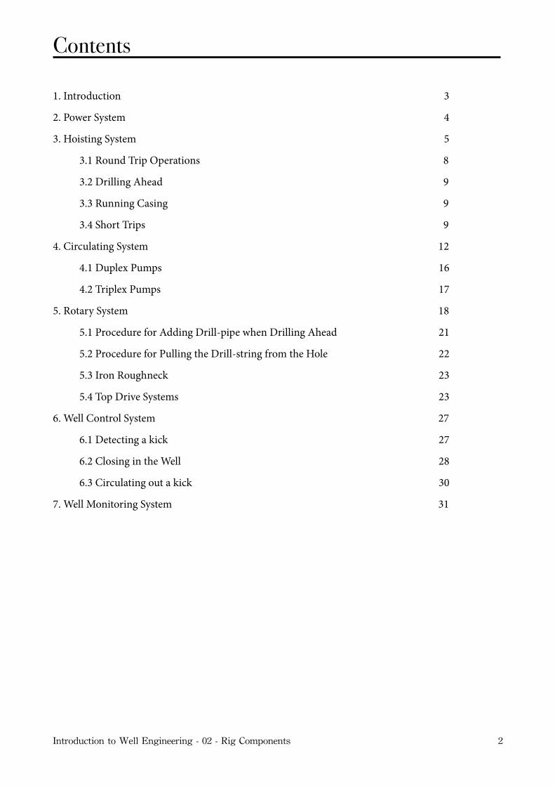
There are many individual pieces of equipment on a rotary drilling rig (Figure 1). These individual pieces of equipment can however be grouped together into six sub-systems. These systems are: the power system; the hoisting system; the circulating system; the rotary system; the well control system, and the well monitoring system. Although the pieces of equipment associated with these systems will vary in design, these systems will be found on all drilling rigs. The equipment discussed below will be found on both land-based, and offshore drilling rigs. The specialized equipment which is required to drill from an offshore drilling rig will be discussed in a subsequent chapter.
Figure 1 - Rotary drilling rig
Introduction to Well Engineering - 02 - Rig Components 3
2. Power System
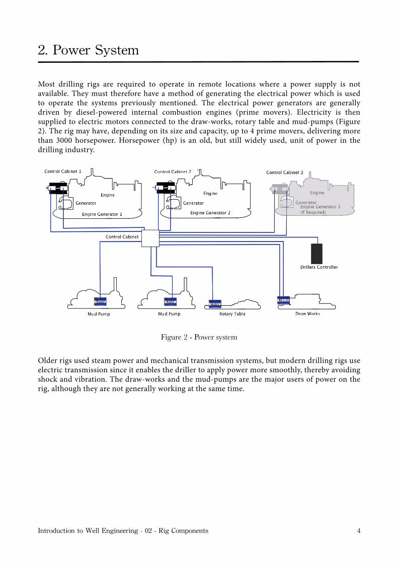
Most drilling rigs are required to operate in remote locations where a power supply is not available. They must therefore have a method of generating the electrical power which is used to operate the systems previously mentioned. The electrical power generators are generally driven by diesel-powered internal combustion engines (prime movers). Electricity is then supplied to electric motors connected to the draw-works, rotary table and mud-pumps (Figure 2). The rig may have, depending on its size and capacity, up to 4 prime movers, delivering more than 3000 horsepower. Horsepower (hp) is an old, but still widely used, unit of power in the drilling industry.
Figure 2 - Power system
Older rigs used steam power and mechanical transmission systems, but modern drilling rigs use electric transmission since it enables the driller to apply power more smoothly, thereby avoiding shock and vibration. The draw-works and the mud-pumps are the major users of power on the rig, although they are not generally working at the same time.
Introduction to Well Engineering - 02 - Rig Components 4
3. Hoisting System
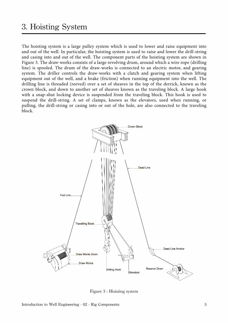
The hoisting system is a large pulley system which is used to lower and raise equipment into and out of the well. In particular, the hoisting system is used to raise and lower the drill-string and casing into and out of the well. The component parts of the hoisting system are shown in Figure 3. The draw-works consists of a large revolving drum, around which a wire rope (drilling line) is spooled. The drum of the draw-works is connected to an electric motor, and gearing system. The driller controls the draw-works with a clutch and gearing system when lifting equipment out of the well, and a brake (friction) when running equipment into the well. The drilling line is threaded (reeved) over a set of sheaves in the top of the derrick, known as the crown block, and down to another set of sheaves known as the traveling block. A large hook with a snap-shut locking device is suspended from the traveling block. This hook is used to suspend the drill-string. A set of clamps, known as the elevators, used when running, or pulling, the drill-string or casing into or out of the hole, are also connected to the traveling block.
Figure 3 - Hoisting system
Introduction to Well Engineering - 02 - Rig Components 5
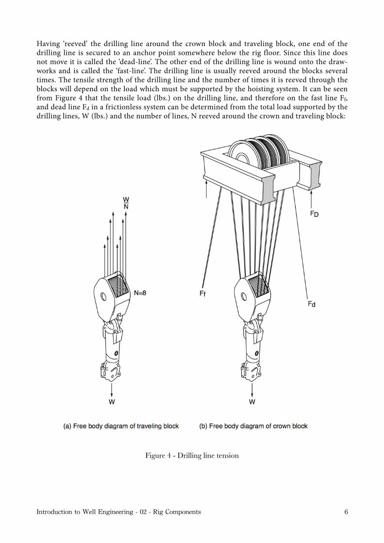
Having ‘reeved’ the drilling line around the crown block and traveling block, one end of the drilling line is secured to an anchor point somewhere below the rig floor. Since this line does not move it is called the ‘dead-line’. The other end of the drilling line is wound onto the draw-works and is called the ‘fast-line’. The drilling line is usually reeved around the blocks several times. The tensile strength of the drilling line and the number of times it is reeved through the blocks will depend on the load which must be supported by the hoisting system. It can be seen from Figure 4 that the tensile load (lbs.) on the drilling line, and therefore on the fast line Ff, and dead line Fd in a frictionless system can be determined from the total load supported by the drilling lines, W (lbs.) and the number of lines, N reeved around the crown and traveling block:
Figure 4 - Drilling line tension
Introduction to Well Engineering - 02 - Rig Components 6
Ff = Fd =WN
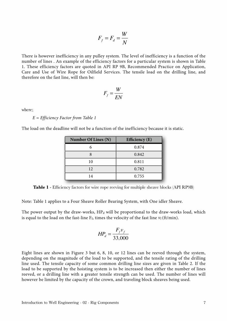
There is however inefficiency in any pulley system. The level of inefficiency is a function of the number of lines . An example of the efficiency factors for a particular system is shown in Table 1. These efficiency factors are quoted in API RP 9B, Recommended Practice on Application, Care and Use of Wire Rope for Oilfield Services. The tensile load on the drilling line, and therefore on the fast line, will then be:
Ff =WEN
where;
E = Efficiency Factor from Table 1
The load on the deadline will not be a function of the inefficiency because it is static.
Number Of Lines (N) Efficiency (E)
6 0.8748 0.842
10 0.81112 0.78214 0.755
Table 1 - Efficiency factors for wire rope reeving for multiple sheave blocks (API RP9B)
Note: Table 1 applies to a Four Sheave Roller Bearing System, with One idler Sheave.
The power output by the draw-works, HPd will be proportional to the draw-works load, which is equal to the load on the fast-line Ff, times the velocity of the fast line vf (ft/min).
Eight lines are shown in Figure 3 but 6, 8, 10, or 12 lines can be reeved through the system, depending on the magnitude of the load to be supported, and the tensile rating of the drilling line used. The tensile capacity of some common drilling line sizes are given in Table 2. If the load to be supported by the hoisting system is to be increased then either the number of lines reeved, or a drilling line with a greater tensile strength can be used. The number of lines will however be limited by the capacity of the crown, and traveling block sheaves being used.
HPd =Ff vf33,000
Introduction to Well Engineering - 02 - Rig Components 7
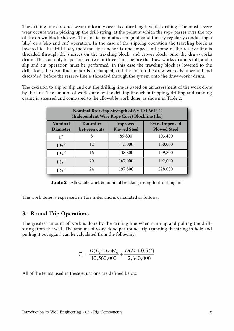
The drilling line does not wear uniformly over its entire length whilst drilling. The most severe wear occurs when picking up the drill-string, at the point at which the rope passes over the top of the crown block sheaves. The line is maintained in good condition by regularly conducting a ‘slip’, or a ‘slip and cut’ operation. In the case of the slipping operation the traveling block is lowered to the drill-floor, the dead line anchor is unclamped and some of the reserve line is threaded through the sheaves on the traveling block, and crown block, onto the draw-works drum. This can only be performed two or three times before the draw-works drum is full, and a slip and cut operation must be performed. In this case the traveling block is lowered to the drill-floor, the dead line anchor is unclamped, and the line on the draw-works is unwound and discarded, before the reserve line is threaded through the system onto the draw-works drum.
The decision to slip or slip and cut the drilling line is based on an assessment of the work done by the line. The amount of work done by the drilling line when tripping, drilling and running casing is assessed and compared to the allowable work done, as shown in Table 2.
Nominal Breaking Strength of 6 x 19 I.W.R.C (Independent Wire Rope Core) Blockline (lbs) Nominal Breaking Strength of 6 x 19 I.W.R.C
(Independent Wire Rope Core) Blockline (lbs) Nominal Breaking Strength of 6 x 19 I.W.R.C
(Independent Wire Rope Core) Blockline (lbs) Nominal Breaking Strength of 6 x 19 I.W.R.C
(Independent Wire Rope Core) Blockline (lbs) Nominal Diameter
Ton-miles between cuts
Improved Plowed Steel
Extra Improved Plowed Steel
1″ 8 89,800 103,400
1 ⅛″ 12 113,000 130,000
1 ¼″ 16 138,800 159,800
1 ⅜″ 20 167,000 192,000
1 ½″ 24 197,800 228,000
Table 2 - Allowable work & nominal breaking strength of drilling line
The work done is expressed in Ton-miles and is calculated as follows:
3.1 Round Trip Operations
The greatest amount of work is done by the drilling line when running and pulling the drill-string from the well. The amount of work done per round trip (running the string in hole and pulling it out again) can be calculated from the following:
All of the terms used in these equations are defined below.
Tr =D(Ls + D)Wm
10,560,000+ D(M + 0.5C)2,640,000
Introduction to Well Engineering - 02 - Rig Components 8
3.2 Drilling Ahead
The amount of work done whilst drilling ahead is expressed in terms of the work performed in making trips. Analysis of the cycle of operations performed during drilling shows that the work done during drilling operations can be expressed as follows:
Td = 3(T2 −T1)
If reaming operations and pulling back the Kelly to add a single or double joint(s) are ignored then the work becomes:
Td = 2(T2 −T1)
3.3 Running Casing
The amount of work done whilst running casing is similar to that for round tripping pipe but since the casing is only run in hole it is one half of the work. The amount of work done can be expressed as:
Tc =D(Lc + D)Wc + 4DM
21,120,000
3.4 Short Trips
The amount of work done in pulling the drill-string back to the previous casing shoe and running back to bottom, for example to ream the hole, can be expressed as in terms of the round trips calculated above:
TST = 2(T4 −T3)
where;
Wm = wt / ft of drillpipe in mud lb / ft( ) Wc = wt / ft of casing in mud lb / ft( ) M = wt. of blocks and elevators lb( ) C = wt. of collars − wt. of drillpipe for same length in mud( )
Tr = Ton −miles for Round Trips TST = Ton −miles for Short Trips Td = Ton −miles whilst drilling Tc = Ton −miles for Casing Operations
Introduction to Well Engineering - 02 - Rig Components 9
T1 = Ton miles for 1 round trip at start depth D1( ) T2 = Ton miles for 1 round trip at final depth D2( )T3 = Ton miles for 1 round trip at depth D3T4 = Ton miles for 1 round trip at depth D4
D = Depth of hole ft( )Ls = Length of drillpipe stand ft( ) Lc = Length of casing joint ft( )
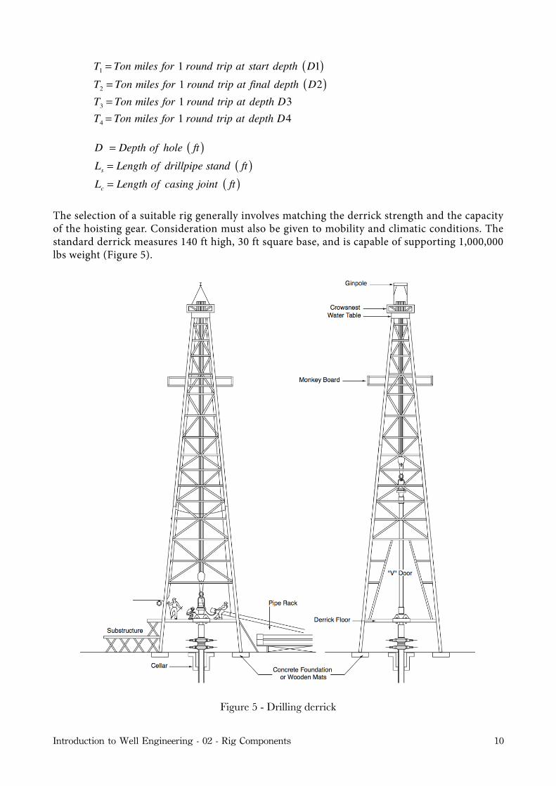
The selection of a suitable rig generally involves matching the derrick strength and the capacity of the hoisting gear. Consideration must also be given to mobility and climatic conditions. The standard derrick measures 140 ft high, 30 ft square base, and is capable of supporting 1,000,000 lbs weight (Figure 5).
Figure 5 - Drilling derrick
Introduction to Well Engineering - 02 - Rig Components 10
The maximum load which the derrick must be able to support can be calculated from the loads shown in Figure 4. The total load will be equal to:
FD =W + Ff + Fd
Introduction to Well Engineering - 02 - Rig Components 11
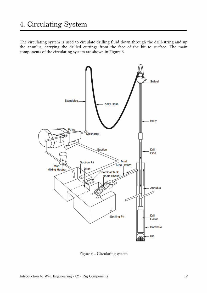
4. Circulating System
The circulating system is used to circulate drilling fluid down through the drill-string and up the annulus, carrying the drilled cuttings from the face of the bit to surface. The main components of the circulating system are shown in Figure 6.
Figure 6 - Circulating system
Introduction to Well Engineering - 02 - Rig Components 12
The main functions of the drilling fluid will be discussed in chapter 9 - Drilling Fluids. However, the two main functions of the drilling fluid are:
To clean and clear the hole of cuttings made by the bit.
To exert a hydrostatic pressure sufficient to prevent formation &uids entering the borehole.
Drilling fluid (mud) is usually a mixture of water, clay, weighting material (such as Barite), and chemicals. The mud is mixed and conditioned in the mud pits, and then circulated downhole by large pumps (slush pumps). The mud is pumped through the standpipe, Kelly hose, swivel, Kelly and down the drill-string. At the bottom of the hole the mud passes through the bit and then up the annulus, carrying cuttings up to surface. At surface the mud is directed from the annulus, through the flow-line (or mud return line) and before it re-enters the mud-pits the drilled cuttings are removed from the drilling mud by the solids removal equipment. Once the drilled cuttings have been removed from the mud it is re-circulated down the hole. The mud is therefore in a continuous circulating system. The properties of the mud are checked continuously to ensure that the desired properties of the mud are maintained. If the properties of the mud change then chemicals will be added to the mud to bring the properties back to those that are required to fulfil the functions of the fluid. These chemicals will be added whilst circulating through the mud pits, or mud with the required properties will be mixed in separate mud pits, and slowly mixed in with the circulating mud.
When the mud-pumps are switched off, the mud will stop flowing through the system and the level of the mud inside the drill-string will equal the level in the annulus. The level in the annulus will be equal to the height of the mud return flow-line. If the mud continues to flow from the annulus when the mud-pumps are switched off then an influx from the formation is occurring and the well should be closed in at the BOP. If the level of fluid in the well falls below the flow-line when the mud-pumps are shut down, losses are occurring (the mud is flowing into the formations downhole). Losses will be discussed at length in a subsequent chapter.
The mud pits are usually a series of large steel tanks, all interconnected and fitted with agitators to maintain the solids, used to maintain the density of the drilling fluid, in suspension. Some pits are used for circulating (e.g. suction pit), and others for mixing and storing fresh mud. Most modern rigs have equipment for storing and mixing bulk additives (e.g. Barite) as well as chemicals (both granular and liquid). The mixing pumps are generally high volume, low pressure centrifugal pumps.
At least 2 slush pumps are installed on the rig. At shallow depths they are usually connected in parallel to deliver high flow rates. As the well goes deeper the pumps may act in series to provide high pressure and lower flow-rates.
Positive displacement type pumps (reciprocating pistons) are used to deliver the high volumes and high pressures required to circulate mud through the drill-string and up the annulus.
There are two types of positive displacement pumps in common use:
Where;d = Linear DiameterL = Stroke Length
V2 =⇡(d2 � d2r)L
4
Where;dr = Rod Diameter
2(V1 + V2)Ev =2⇡(2d2 � d2r)LEv
4
Q =(2d2 � d2r)LEvR
147
Q = Flow Rate(gpm)d = Linear Diameter(in.)rr = Rod Diameter(in.)L = Stroke Length(in.)R = Pump Speed(spm)
3V1Ev =3⇡d2LEv
4
Q =d2LEvR
98.03
Q = Flow Rate(gpm)d = Linear Diameter(in.)L = Stroke Length(in.)R = Pump Speed(spm)
P⇡ =wT
2⇡
P⇡ = Power(hp)w = Rotary Speed(rpm)rr = Torque(ft-lbf)
P = 0.052 ⇤MW ⇤ TV D
Section Modulus = IC
Moment of IneritaExternalRadius of Tube
L = WOBw
P = Hydrostatic Pressure(psi)MW = Mud weight(ppg)TV D = Vertical Height of Mud Column(ft)
Pc = 0.052 ⇤MW ⇤ TV D
Pc = Collapse Pressure(psi)MW = Mud Weight(ppg)TV D = True Vertical Depth(ft) at which Pc acts
(i) Duplex (2 cylinders) - double acting(ii) Triplex (3 cylinders) - single acting
2
Triplex pumps are generally used in offshore rigs, and Duplex pumps on land rigs. Duplex pumps (Figure 7) have two cylinders and are double-acting (i.e. pump on the up-stroke and the Introduction to Well Engineering - 02 - Rig Components 13

down-stroke). Triplex pumps (Figure 8) have three cylinders and are single-acting (i.e. pump on the up-stroke only). Triplex pumps have the advantages of being lighter, giving smoother discharge and having lower maintenance costs.
Piston Rod
Discharge Valves
Intake Valves
Piston Rod
Discharge Valves
Intake Valves
Figure 7 - Duplex pump
Piston Rod
Discharge Valve
Intake Valve
Piston Rod
Discharge Valve
Intake Valve
Figure 8 - Triplex pump
The discharge line from the mud-pumps is connected to the standpipe, a steel pipe mounted vertically on one leg of the derrick. A flexible rubber hose (Kelly hose) connects the top of the standpipe to the swivel, via the gooseneck. The swivel will be discussed in the section on the rotary system below (page 18).
Once the mud has been circulated round the system it will contain suspended drilled cuttings, perhaps some gas, and other contaminants. These must be removed before the mud is recycled. The mud passes over a shale shaker, which is basically a vibrating screen. This will remove the larger particles, while allowing the residue (underflow) to pass into settling tanks. The finer material can be removed using other solids removal equipment. If the mud contains gas from the formation it will be passed through a de-gasser, which separates the gas from the liquid mud. Having passed through all the mud processing equipment the mud is returned to the mud tanks for recycling.
There will be at least two pumps on the rig, and these will be connected by a mud manifold. When drilling large diameter holes near surface both pumps are connected in parallel to
Introduction to Well Engineering - 02 - Rig Components 14
produce high flow rates. When drilling smaller size holes only one pump is usually necessary, and the other is used as a back-up.
The advantages of using reciprocating positive displacement pumps are that they can be used to:
Pump &uids containing high solids content.
Operate over a wide range of pressures and &ow rates.
Also, they are:
Reliable.
Simple to operate.
Easy to maintain.
The flow-rate and pressure delivered by the pump depends on the size of sleeve (liner) that is placed in the cylinders of the pumps. A liner is basically a replaceable tube which is placed inside the cylinder to decrease the bore.
The Power output of a mud pump is measured in Hydraulic Horsepower. The horsepower delivered by a pump can be calculated from the following:
where;HHP = HorsepowerQ = Flow rate gpm( ) P = Pressure psi( )
Since the power rating of a pump is limited (generally to about 1600 hp), and the power consumption is a product of the output pressure and flow-rate, the use of a smaller liner will increase the discharge pressure, but reduce the flow rate and vice versa. It can be seen from the above equation that when operating at the maximum pump rate, an increase in the pump pressure will require a decrease in the flow-rate and vice versa. The pump pressure will generally be limited by the pressure rating of the flow-lines on the rig, while the flow-rate will be limited by the size of the liners in the pump, and the rate at which the pump operates.
The mechanical efficiency (Em) of a pump is related to the operation of the prime movers and transmission system. In most cases Em is taken as 0.9. Volumetric efficiency (Ev) depends on the type of pump being used, and is usually between 0.9 and 1.0. The overall efficiency is the product of Em and Ev.
HPP = PQ1714
Introduction to Well Engineering - 02 - Rig Components 15
4.1 Duplex Pumps
A schematic diagram of a duplex pump is shown in Figure 7. As the piston moves forward discharging fluid ahead of it, the inlet port allows fluid to enter the chamber behind it. On the return the fluid behind the piston is discharged (i.e. on the rod side) while fluid on the other side is allowed in. The theoretical displacement on the forward stroke is:
where;
d = Liner diameterL = Stroke length
on the return stroke;
V2 =π (d 2 − dr
2 )L4
where;
dr = Rod diameter
Taking account of the 2 cylinders, and the volumetric efficiency Ev, the total displacement (in gallons) of one pump revolution is:
Where;d = Linear DiameterL = Stroke Length
V2 =⇡(d2 � d2r)L
4
Where;dr = Rod Diameter
2(V1 + V2)Ev =2⇡(2d2 � d2r)LEv
4
Q =(2d2 � d2r)LEvR
147
Q = Flow Rate(gpm)d = Linear Diameter(in.)rr = Rod Diameter(in.)L = Stroke Length(in.)R = Pump Speed(spm)
3V1Ev =3⇡d2LEv
4
Q =d2LEvR
98.03
Q = Flow Rate(gpm)d = Linear Diameter(in.)L = Stroke Length(in.)R = Pump Speed(spm)
P⇡ =wT
2⇡
P⇡ = Power(hp)w = Rotary Speed(rpm)rr = Torque(ft-lbf)
P = 0.052 ⇤MW ⇤ TV D
Section Modulus = IC
Moment of IneritaExternalRadius of Tube
L = WOBw
P = Hydrostatic Pressure(psi)MW = Mud weight(ppg)TV D = Vertical Height of Mud Column(ft)
Pc = 0.052 ⇤MW ⇤ TV D
Pc = Collapse Pressure(psi)MW = Mud Weight(ppg)TV D = True Vertical Depth(ft) at which Pc acts
(i) Duplex (2 cylinders) - double acting(ii) Triplex (3 cylinders) - single acting
2
The pump output can be obtained by multiplying this by the pump speed in revolutions per minute. (In oilfield terms 1 complete pump revolution = 1 stroke, therefore pump speed is usually given in strokes per minute) e.g. a duplex pump operating at a speed of 20 spm means 80 cylinder volumes per minute. Pump output is given by:
V1 =πd 2L4
Q = (2d2 − dr
2 )LEvR147
Introduction to Well Engineering - 02 - Rig Components 16
where;Q = Flow rate gpm( )d = Liner diameter in.( )dr = Rod diameter in.( ) L = Stroke length in.( ) R = Pump speed spm( )
These flow rates are readily available in manufacturers’ pump tables.
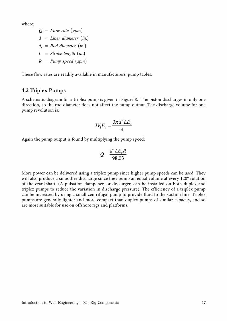
4.2 Triplex Pumps
A schematic diagram for a triplex pump is given in Figure 8. The piston discharges in only one direction, so the rod diameter does not affect the pump output. The discharge volume for one pump revolution is:
3V1Ev =3πd 2LEv
4
Again the pump output is found by multiplying the pump speed:
Q = d2LEvR98.03
More power can be delivered using a triplex pump since higher pump speeds can be used. They will also produce a smoother discharge since they pump an equal volume at every 120° rotation of the crankshaft. (A pulsation dampener, or de-surger, can be installed on both duplex and triplex pumps to reduce the variation in discharge pressure). The efficiency of a triplex pump can be increased by using a small centrifugal pump to provide fluid to the suction line. Triplex pumps are generally lighter and more compact than duplex pumps of similar capacity, and so are most suitable for use on offshore rigs and platforms.
Introduction to Well Engineering - 02 - Rig Components 17

5. Rotary System
The rotary system is used to rotate the drill-string, and therefore turn the drill-bit, on the bottom of the borehole. The rotary system includes all the equipment used to achieve bit rotation (Figure 9).
The swivel is positioned at the top of the drill-string. It has 3 functions:
Supports the weight of the drill-string.
Permits the string to rotate.
Allows mud to be pumped while the string is rotating.
The hook of the traveling block is latched into the bail of the swivel, and the Kelly hose is attached to the gooseneck of the swivel.
The Kelly is the first section of pipe below the swivel. It is normally about 40 ft long, and has an outer hexagonal cross-section. It must have this hexagonal (or sometimes square) shape to transmit rotation from the rotary table to the drill-string. The Kelly has a right hand thread connection on its lower [pin] end, and a left hand thread connection on its upper [box] end. A short, inexpensive piece of pipe called a Kelly saver sub is used between the Kelly and the first joint of drill-pipe. The Kelly saver sub prevents excessive wear of the threads of the connection on the Kelly, due to continuous make up and breakout of the Kelly whilst drilling. Kelly ‘cocks’ are valves installed at either end of the Kelly to isolate high pressures, and prevent backflow from the well if an influx occurs at the bottom of the well.The rotary table is located on the drill floor and can be turned in both clockwise and anti-clockwise directions. It is controlled from the drillers ‘console’. This rotating table has a square recess and four post holes. A large cylindrical sleeve, called a master bushing, is used to protect the rotary table.
The torque from the rotary table is transmitted to the Kelly through the four pins on a device which runs along the length of the Kelly, known as the Kelly bushing. The Kelly bushing has 4 pins, which fit into the post holes of the rotary table. When power is supplied to the rotary table torque is transmitted from the rotating table to the Kelly via the Kelly bushing. The power requirements of the rotary table can be determined from:
where;Prt = Power hp( )ω = Rotary Speed rpm( ) T = Torque ft − lbf( )
Prt =wT2π
Introduction to Well Engineering - 02 - Rig Components 18
lbf )W

Figure 9 - Rotary system
Introduction to Well Engineering - 02 - Rig Components 19
Slips are used to suspend pipe in the rotary table when making or breaking a connection. Slips are made up of three tapered, hinged segments, which are wrapped around the top of the drill-pipe, so that it can be suspended from the rotary table when the top connection of the drill-pipe is being screwed or unscrewed. The inside of the slips have a serrated surface, which grips the pipe (Figure 9).
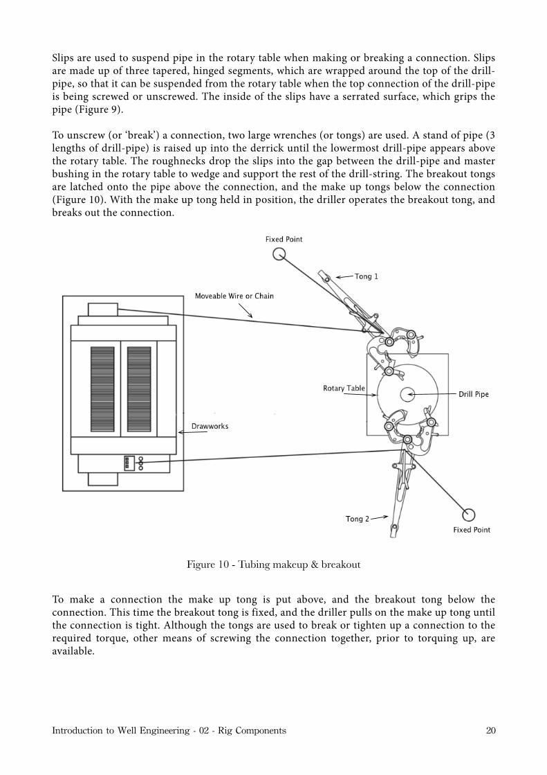
To unscrew (or ‘break’) a connection, two large wrenches (or tongs) are used. A stand of pipe (3 lengths of drill-pipe) is raised up into the derrick until the lowermost drill-pipe appears above the rotary table. The roughnecks drop the slips into the gap between the drill-pipe and master bushing in the rotary table to wedge and support the rest of the drill-string. The breakout tongs are latched onto the pipe above the connection, and the make up tongs below the connection (Figure 10). With the make up tong held in position, the driller operates the breakout tong, and breaks out the connection.
Figure 10 - Tubing makeup & breakout
To make a connection the make up tong is put above, and the breakout tong below the connection. This time the breakout tong is fixed, and the driller pulls on the make up tong until the connection is tight. Although the tongs are used to break or tighten up a connection to the required torque, other means of screwing the connection together, prior to torquing up, are available.
Introduction to Well Engineering - 02 - Rig Components 20
For making up the Kelly, the lower tool joint is fixed by a tong, while the Kelly is rotated by a Kelly spinner. The Kelly spinner is a machine which is operated by compressed air.
A drill-pipe spinner (power tongs) may be used to make up or backoff a connection (powered by compressed air).
For making up some subs or special tools (e.g. MWD subs) a chain tong is oen used.
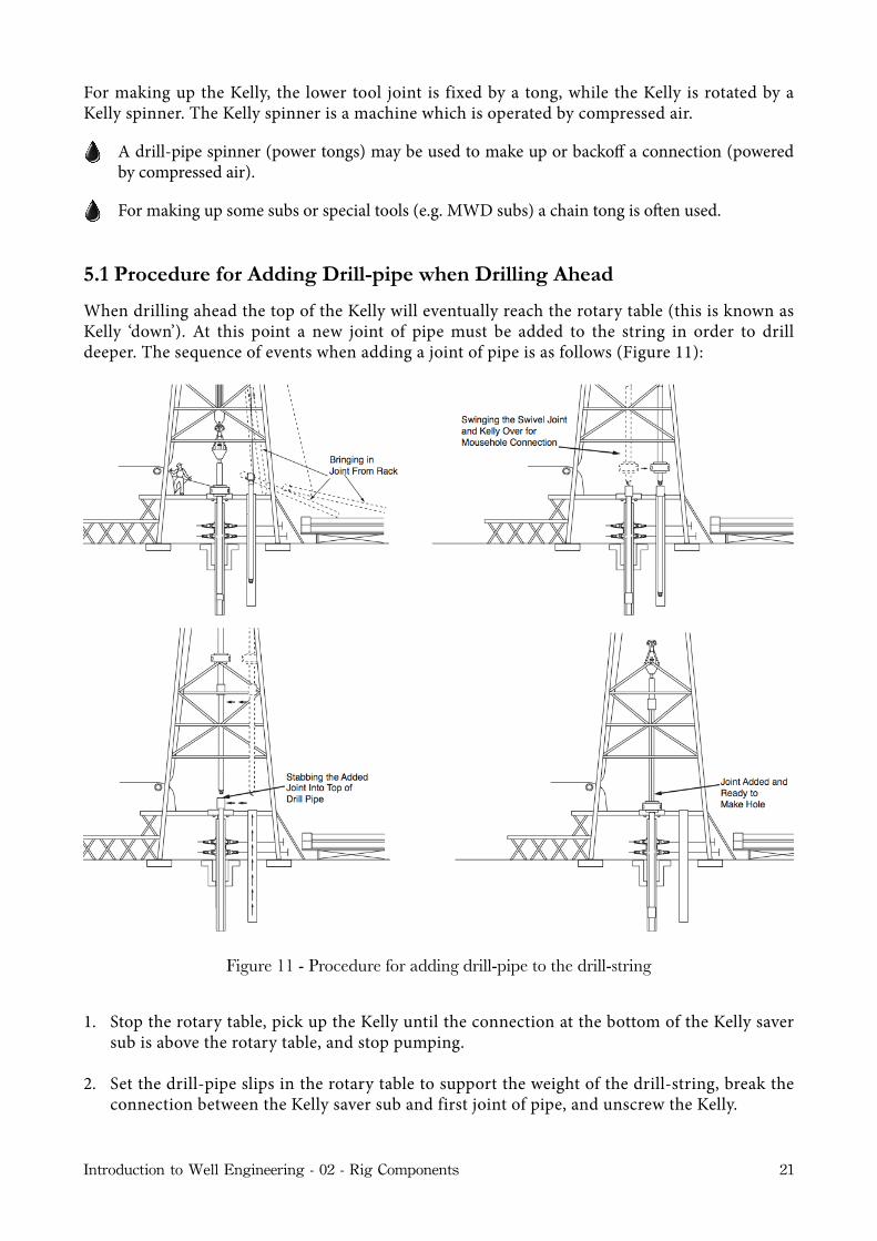
5.1 Procedure for Adding Drill-pipe when Drilling Ahead
When drilling ahead the top of the Kelly will eventually reach the rotary table (this is known as Kelly ‘down’). At this point a new joint of pipe must be added to the string in order to drill deeper. The sequence of events when adding a joint of pipe is as follows (Figure 11):
Figure 11 - Procedure for adding drill-pipe to the drill-string
1. Stop the rotary table, pick up the Kelly until the connection at the bottom of the Kelly saver sub is above the rotary table, and stop pumping.
2. Set the drill-pipe slips in the rotary table to support the weight of the drill-string, break the connection between the Kelly saver sub and first joint of pipe, and unscrew the Kelly.
Introduction to Well Engineering - 02 - Rig Components 21
3. Swing the Kelly over to the next joint of drill-pipe which is stored in the mouse-hole (an opening through the floor near the rotary table).
4. Stab the Kelly into the new joint, screw it together and use tongs to tighten the connection.
5. Pick up the Kelly, and new joint, out of the mousehole, and swing the assembly back to the rotary table.
6. Stab the new joint into the connection above the rotary table, and make up the connection.
7. Pick up the Kelly, pull the slips and run in hole until the Kelly bushing engages the rotary table.
8. Start pumping, run the bit to bottom, rotate and drill ahead.
This procedure must be repeated every 30 ft as drilling proceeds.
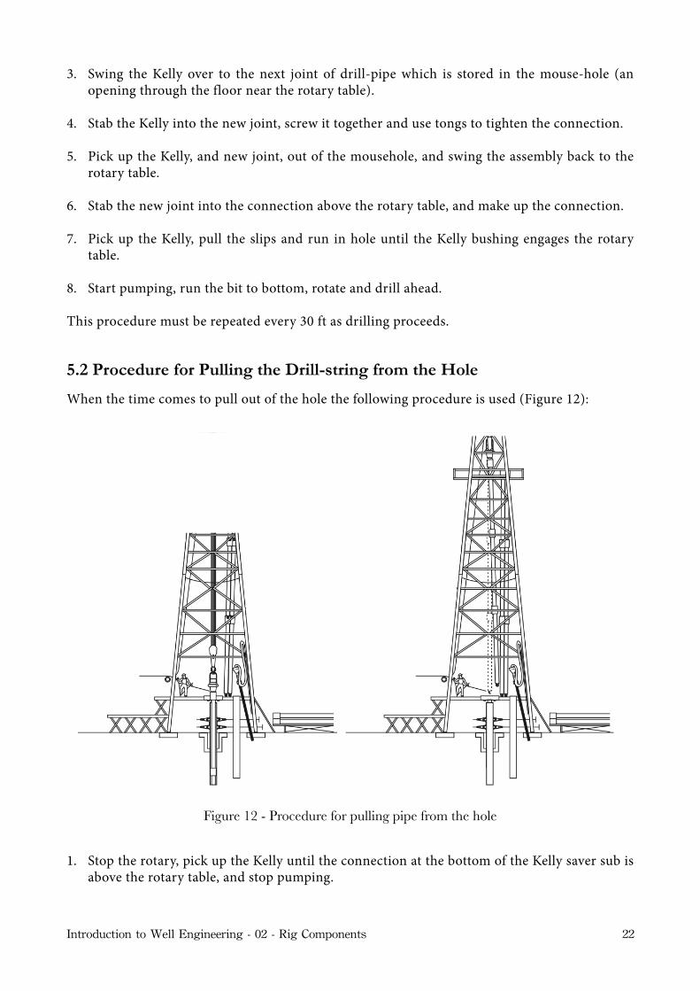
5.2 Procedure for Pulling the Drill-string from the Hole
When the time comes to pull out of the hole the following procedure is used (Figure 12):
Figure 12 - Procedure for pulling pipe from the hole
1. Stop the rotary, pick up the Kelly until the connection at the bottom of the Kelly saver sub is above the rotary table, and stop pumping.
Introduction to Well Engineering - 02 - Rig Components 22

2. Set the drill-pipe slips, break out the Kelly and set the Kelly back in the rat-hole (another hole in the rig floor which stores the Kelly and swivel when not in use).
3. Remove the swivel from the hook (i.e. Kelly, Kelly bushing, swivel and Kelly hose all stored in rathole).
4. Latch the elevators onto the top connection of the drill-pipe, pick up the drill-pipe and remove the slips. Pull the top of the drill-pipe until the top of the drill-pipe is at the top of the derrick and the second connection below the top of the drill-pipe is exposed at the rotary table. A stand (3 joints of pipe) is now exposed above the rotary table.
5. Roughnecks use tongs to break out the connection at the rotary table, and carefully swing the bottom of the stand over to one side. Stands must be stacked in an orderly fashion.
6. The Derrick-man, on the ‘monkey board’, grabs the top of the stand, and sets it back in the ‘fingerboard’.
When running pipe into the hole it is basically the same procedure in reverse.
5.3 Iron Roughneck
On some rigs a mechanical device known as an iron roughneck may be used to make up and breakout connections. This machine runs on rails attached to the rig floor, and is easily set aside when not in use. Its mobility allows it to carry out mousehole connections when the tracks are correctly positioned. The device consists of a spinning wrench and torque wrench, which are both hydraulically operated. Advantages offered by this device include controlled torque, minimal damage to threads (thereby increasing the service life of the drill-pipe), and reduced crew fatigue.
5.4 Top Drive Systems
Most offshore drilling rigs now have top drive systems installed in the derrick. A top drive system consists of a power swivel, driven by a 1000 hp dc electric motor. This power swivel is connected to the traveling block, and both components run along a vertical guide track which extends from below the crown block, to within 3 meters of the rig floor. The electric motor delivers over 25000 ft-lbs torque, and can operate at 300 rpm. The power swivel is remotely controlled from the driller’s console, and can be set back if necessary to allow conventional operations to be carried out.
A pipe handling unit, which consists of a 500 ton elevator system and a torque wrench, is suspended below the power swivel. These are used to break out connections. A hydraulically actuated valve below the power swivel is used as a Kelly cock.
A top drive system replaces the functions of the rotary table, and allows the drill-string to be rotated from the top, using the power swivel instead of a Kelly and rotary table (Figure 13). The power swivel replaces the conventional rotary system, although a conventional rotary table would generally, also be available as a back up.
The advantages of this system are:
Introduction to Well Engineering - 02 - Rig Components 23
It enables complete 90 stands of pipe to be added to the string rather than the conventional 30 singles. is saves rig time since 2 out of every 3 connections are eliminated. It also makes coring operations more efficient.
When tripping out of the hole the power swivel can be easily stabbed into the string to allow circulation and string rotation when pulling out of hole, if necessary (e.g. to prevent stuck pipe).
When tripping into the hole the power swivel can be connected to allow any bridges to be drilled out without having to pick up the Kelly.
Introduction to Well Engineering - 02 - Rig Components 24

Figure 13 - Top drive system
Introduction to Well Engineering - 02 - Rig Components 25
The procedure for adding a stand, when using a top drive system is as follows:
1. Suspend the drill-string from slips, as in the conventional system, and stop circulation.
2. Break out the connection at the bottom of the power sub.
3. Unlatch the elevators, and raise the block to the top of the derrick.
4. Catch the next stand in the elevators, and stab the power sub into the top of the stand.
5. Make up the top and bottom connections of the stand.
6. Pick up the string, pull slips, start pumps and drill ahead.
Top drive systems are now very widely used. The disadvantages of a top drive system are:
Increase in topside weight on the rig.
Electric and hydraulic control lines must be run up inside the derrick.
When drilling from a semi-submersible under heaving conditions the drill-string may ‘bottom out’ during connections when the string is hung off in the slips. is could be overcome by drilling with doubles, and a drilling sub, which could be broken out like a Kelly. is method however would reduce the time-saving advantages of the top drive system.
Introduction to Well Engineering - 02 - Rig Components 26
6. Well Control System
The function of the well control system is to prevent the uncontrolled flow of formation fluids from the well-bore. When the drill-bit enters a permeable formation the pressure in the pore space of the formation may be greater than the hydrostatic pressure exerted by the mud column. If this is so, formation fluids will enter the well-bore and start displacing mud from the hole. Any influx of formation fluids (oil, gas or water) in the borehole is known as a kick.
The well control system is designed to:
Detect a kick.
Close-in the well at surface.
Remove the formation &uid which has &owed into the well.
Make the well safe.
Failure to do this results in the uncontrolled flow of fluids, known as a blow-out, which may cause loss of lives and equipment, damage to the environment and the loss of oil or gas reserves. Primary well control is achieved by ensuring that the hydrostatic mud pressure is sufficient to overcome formation pressure. Hydrostatic pressure is calculated from:
where;
Phy = Hydrostatic pressure(psi)MW = Mud weight (ppg)TVD =Vertical height of mud column( ft)
Primary control will only be maintained by ensuring that the mud weight is kept at the prescribed value, and keeping the hole filled with mud. Secondary well control is achieved by using valves on the BOP to prevent the flow of fluid from the well, until such time as the well can be made safe.
6.1 Detecting a kick
There are many signs that a driller will become aware of when a kick has taken place. The first sign that a kick has taken place could be a sudden increase in the level of mud in the pits. Another sign may be mud flowing out of the well, even when the pumps are shut down (i.e. without circulating). Mechanical devices such as pit level indicators or mud flowmeters, which trigger off alarms to alert the rig crew that an influx has taken place, are placed on all rigs. Regular ‘pit drills’ are carried out to ensure that the driller and the rig crew can react quickly in the event of a kick.
Phy = 0.052 x MW x TVD
Introduction to Well Engineering - 02 - Rig Components 27
6.2 Closing in the Well
Blow-Out Preventors (BOP’s) must be installed to cope with any kicks that may occur. BOP’s are basically high pressure valves which seal off the top of the well. On land rigs, or fixed platforms, the BOP stack is located directly beneath the rig floor. On floating rigs the BOP stack is installed on the sea bed. In either case the valves are hydraulically operated from the rig floor.
There are two basic types of BOP.
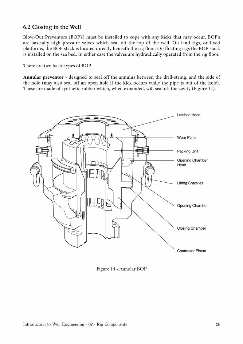
Annular preventor - designed to seal off the annulus between the drill-string, and the side of the hole (may also seal off an open hole if the kick occurs while the pipe is out of the hole). These are made of synthetic rubber which, when expanded, will seal off the cavity (Figure 14).
Figure 14 - Annular BOP
Introduction to Well Engineering - 02 - Rig Components 28

Ram type preventor - designed to seal off the annulus by ‘ramming’ large rubber-faced blocks of steel together. Different types are available:
Blind rams - seal off in open hole.
Pipe rams - seal off around drill-pipe (Figure 15).
Shear rams - sever drill-pipe (used as last resort).
Figure 15 - Ram type BOP
Introduction to Well Engineering - 02 - Rig Components 29
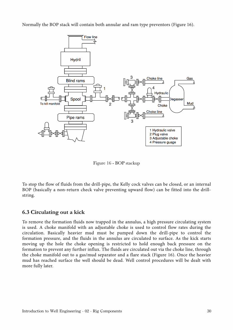
Normally the BOP stack will contain both annular and ram type preventors (Figure 16).
Figure 16 - BOP stackup
To stop the flow of fluids from the drill-pipe, the Kelly cock valves can be closed, or an internal BOP (basically a non-return check valve preventing upward flow) can be fitted into the drill-string.
6.3 Circulating out a kick
To remove the formation fluids now trapped in the annulus, a high pressure circulating system is used. A choke manifold with an adjustable choke is used to control flow rates during the circulation. Basically heavier mud must be pumped down the drill-pipe to control the formation pressure, and the fluids in the annulus are circulated to surface. As the kick starts moving up the hole the choke opening is restricted to hold enough back pressure on the formation to prevent any further influx. The fluids are circulated out via the choke line, through the choke manifold out to a gas/mud separator and a flare stack (Figure 16). Once the heavier mud has reached surface the well should be dead. Well control procedures will be dealt with more fully later.
Introduction to Well Engineering - 02 - Rig Components 30

7. Well Monitoring System
Safety requires constant monitoring of the drilling process. If drilling problems are detected early remedial action can be taken quickly, thereby avoiding major problems. The driller must be aware of how drilling parameters are changing (e.g. WOB, RPM, pump rate, pump pressure, gas content of mud etc.). For this reason there are various gauges installed on the driller’s console where he can read them easily.
Another useful aid in monitoring the well is mud-logging. The mud-logger carefully inspects rock cuttings taken from the shale shaker at regular intervals. By calculating ‘lag’ times the cuttings descriptions can be matched with the depth, and a log of the formations being drilled can be produced. This log is useful to the geologist in comparing this well with others in the vicinity. Mud-loggers also monitor the gas present in the mud by using gas chromatography.
Introduction to Well Engineering - 02 - Rig Components 31