Embed Size (px)
Citation preview
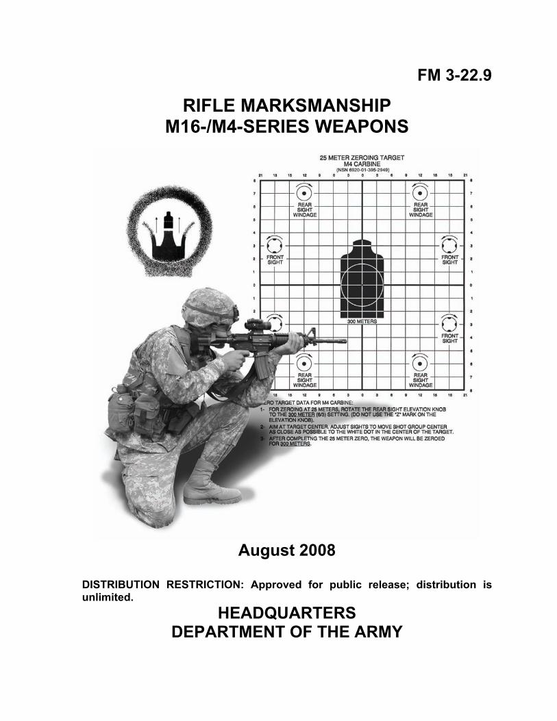
FM 3-22.9
RIFLE MARKSMANSHIP M16-/M4-SERIES WEAPONS
August 2008
DISTRIBUTION RESTRICTION: Approved for public release; distribution is unlimited.
HEADQUARTERS DEPARTMENT OF THE ARMY
12 August 2008 FM 3-22.9 2-1
Chapter 2
Weapon Characteristics, Accessories, and Ammunition This chapter describes the general components, characteristics, accessories, and ammunition for M16- and M4-series weapons, and includes a brief explanation of how to mount the various accessories.
SECTION I. RIFLES AND CARBINES All M16-/M4-series weapons are magazine-fed, gas-operated, air-cooled, shoulder-fired 5.56-millimeter weapons. This section describes the general characteristics and components of M16-/M4-series weapons.
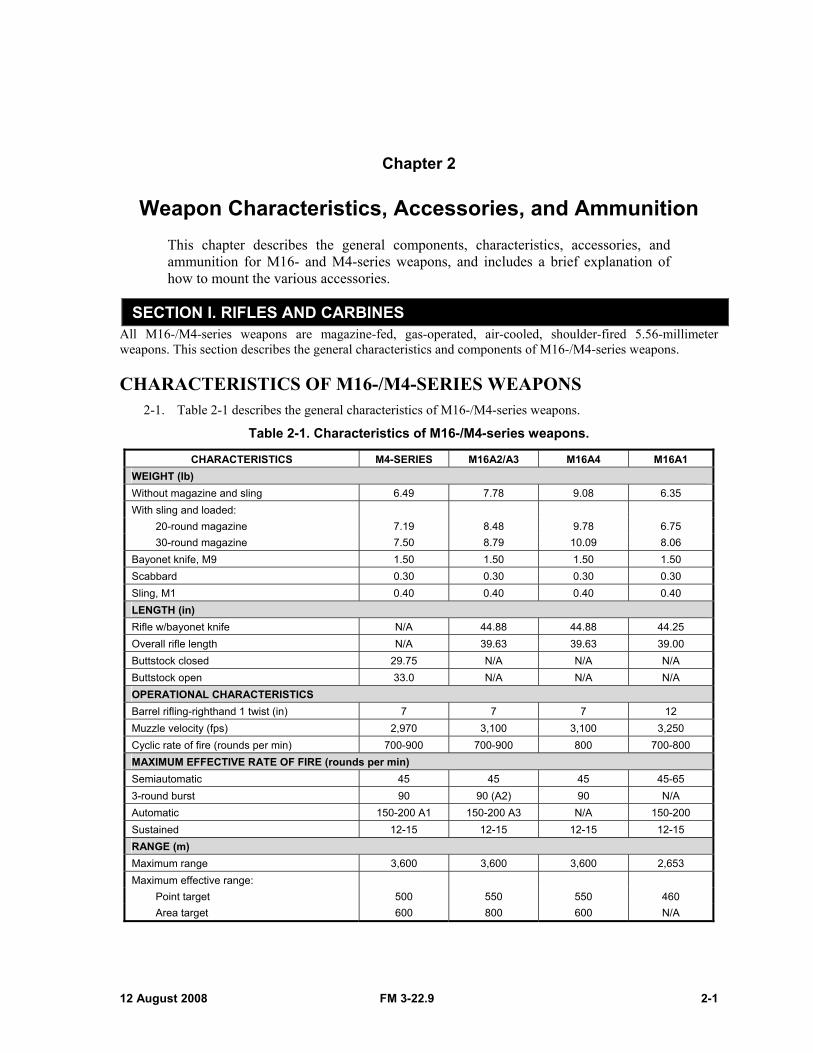
CHARACTERISTICS OF M16-/M4-SERIES WEAPONS 2-1. Table 2-1 describes the general characteristics of M16-/M4-series weapons.
Table 2-1. Characteristics of M16-/M4-series weapons.
CHARACTERISTICS M4-SERIES M16A2/A3 M16A4 M16A1 WEIGHT (lb) Without magazine and sling 6.49 7.78 9.08 6.35 With sling and loaded: 20-round magazine 7.19 8.48 9.78 6.75 30-round magazine 7.50 8.79 10.09 8.06 Bayonet knife, M9 1.50 1.50 1.50 1.50 Scabbard 0.30 0.30 0.30 0.30 Sling, M1 0.40 0.40 0.40 0.40 LENGTH (in) Rifle w/bayonet knife N/A 44.88 44.88 44.25 Overall rifle length N/A 39.63 39.63 39.00 Buttstock closed 29.75 N/A N/A N/A Buttstock open 33.0 N/A N/A N/A OPERATIONAL CHARACTERISTICS Barrel rifling-righthand 1 twist (in) 7 7 7 12 Muzzle velocity (fps) 2,970 3,100 3,100 3,250 Cyclic rate of fire (rounds per min) 700-900 700-900 800 700-800 MAXIMUM EFFECTIVE RATE OF FIRE (rounds per min) Semiautomatic 45 45 45 45-65 3-round burst 90 90 (A2) 90 N/A Automatic 150-200 A1 150-200 A3 N/A 150-200 Sustained 12-15 12-15 12-15 12-15 RANGE (m) Maximum range 3,600 3,600 3,600 2,653 Maximum effective range: Point target 500 550 550 460 Area target 600 800 600 N/A
Chapter 2
2-4 FM 3-22.9 12 August 2008
MECHANICALLY ZEROING THE M4/M4A1 CARBINE OR M4 MWS
NOTE: Mechanically zeroing the weapon is only necessary when the weapon zero is questionable, the weapon is newly assigned to the unit, or the weapon sights have been serviced.
2-3. To mechanically zero an M4/M4A1 or M4 MWS—
NOTE: Reference the weapon components using the numbers listed in Figure 2-4.
Figure 2-4. M4/M4A1 or M4 MWS mechanical zero.
(1) Adjust the front sightpost (1) until the base of the front sightpost is flush with the front sightpost housing (2).
(2) Turn the elevation knob (3, shown as viewed from above) counterclockwise until the rear sight assembly (4) rests flush with the detachable carrying handle and the 6/3 marking is aligned with the index line (5) on the left side of the carrying handle.
(3) Position the apertures (6) so the unmarked aperture is up and the 0-200 meter aperture is down. (4) Turn the windage knob (7) to align the index mark (8) on the 0-200 meter aperture with the long
center index line on the rear sight assembly.
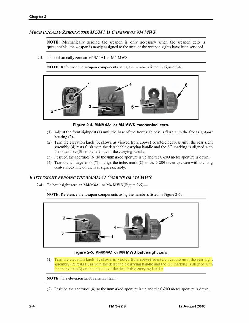
BATTLESIGHT ZEROING THE M4/M4A1 CARBINE OR M4 MWS 2-4. To battlesight zero an M4/M4A1 or M4 MWS (Figure 2-5)—
NOTE: Reference the weapon components using the numbers listed in Figure 2-5.
Figure 2-5. M4/M4A1 or M4 MWS battlesight zero.
(1) Turn the elevation knob (1, shown as viewed from above) counterclockwise until the rear sight assembly (2) rests flush with the detachable carrying handle and the 6/3 marking is aligned with the index line (3) on the left side of the detachable carrying handle.
NOTE: The elevation knob remains flush.
(2) Position the apertures (4) so the unmarked aperture is up and the 0-200 meter aperture is down.
Weapon Characteristics, Accessories, and Ammunition
12 August 2008 FM 3-22.9 2-5
(3) Turn the windage knob (5) to align the index mark (6) on the 0-200 meter aperture with the long center index line on the rear sight assembly.
NOTE: The “Z” marking on the elevation knob (employed when using the M4-series weapon's detachable carrying handle) should be ignored. The “Z” marking is only used when the M16A4 is being zeroed.
2-5. Table 2-2 shows how much one click of elevation or windage will move the strike of the round at ranges from 25 to 500 meters.
Table 2-2. Point of impact for the M4/M4A1 and M4 MWS.
RANGE (m) 25 100 200 300 400 500 Elevation 3/4 in
0.9 cm 1 3/8 in 3.5 cm
2 3/4 in 7 cm
4 1/8 in 10.5 cm
5 1/2 in 14 cm
6 7/8 in 17.5 cm
Windage 1/8 in 0.3 cm
1/2 in 1.25 cm
1 in 2.5 cm
1 1/2 in 3.8 cm
2 in 5 cm
2 1/2 in 6.3 cm
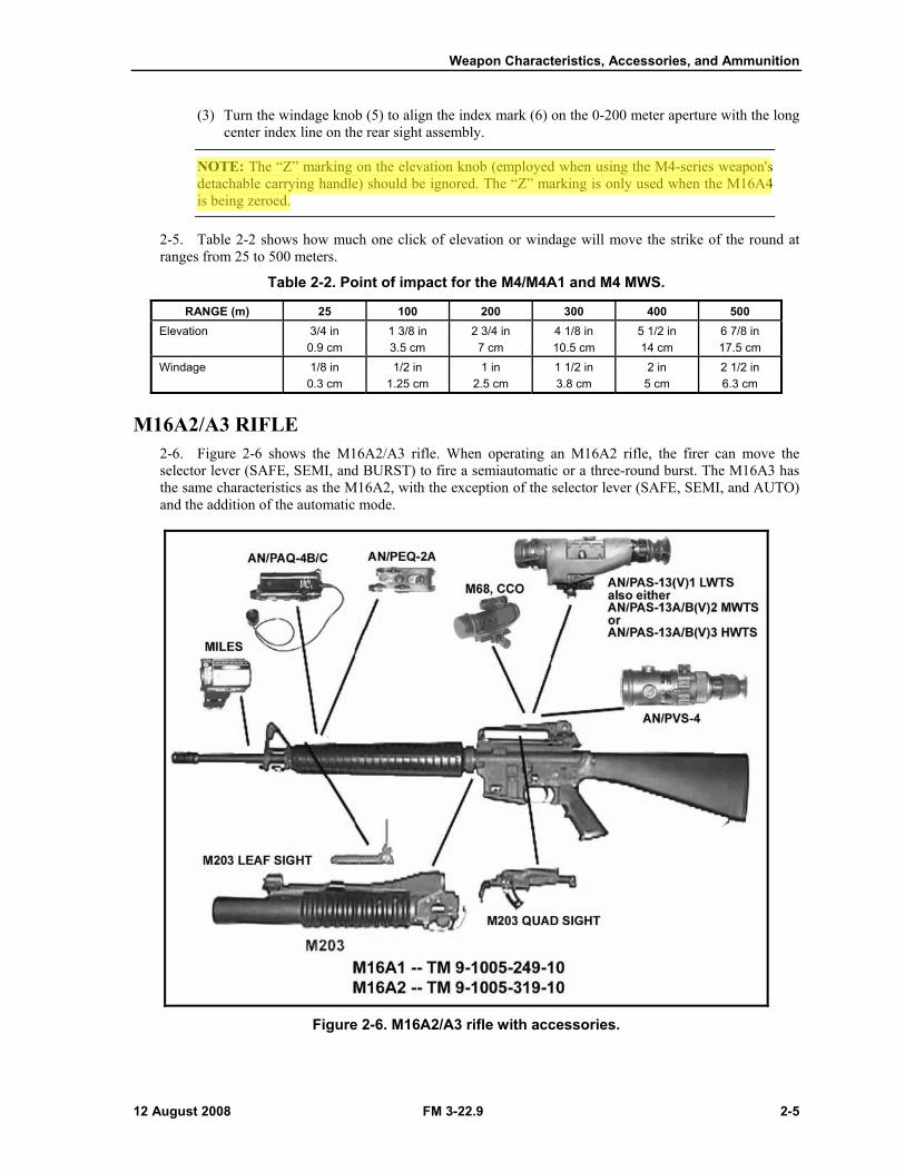
M16A2/A3 RIFLE 2-6. Figure 2-6 shows the M16A2/A3 rifle. When operating an M16A2 rifle, the firer can move the selector lever (SAFE, SEMI, and BURST) to fire a semiautomatic or a three-round burst. The M16A3 has the same characteristics as the M16A2, with the exception of the selector lever (SAFE, SEMI, and AUTO) and the addition of the automatic mode.
Figure 2-6. M16A2/A3 rifle with accessories.
Weapon Characteristics, Accessories, and Ammunition
12 August 2008 FM 3-22.9 2-17
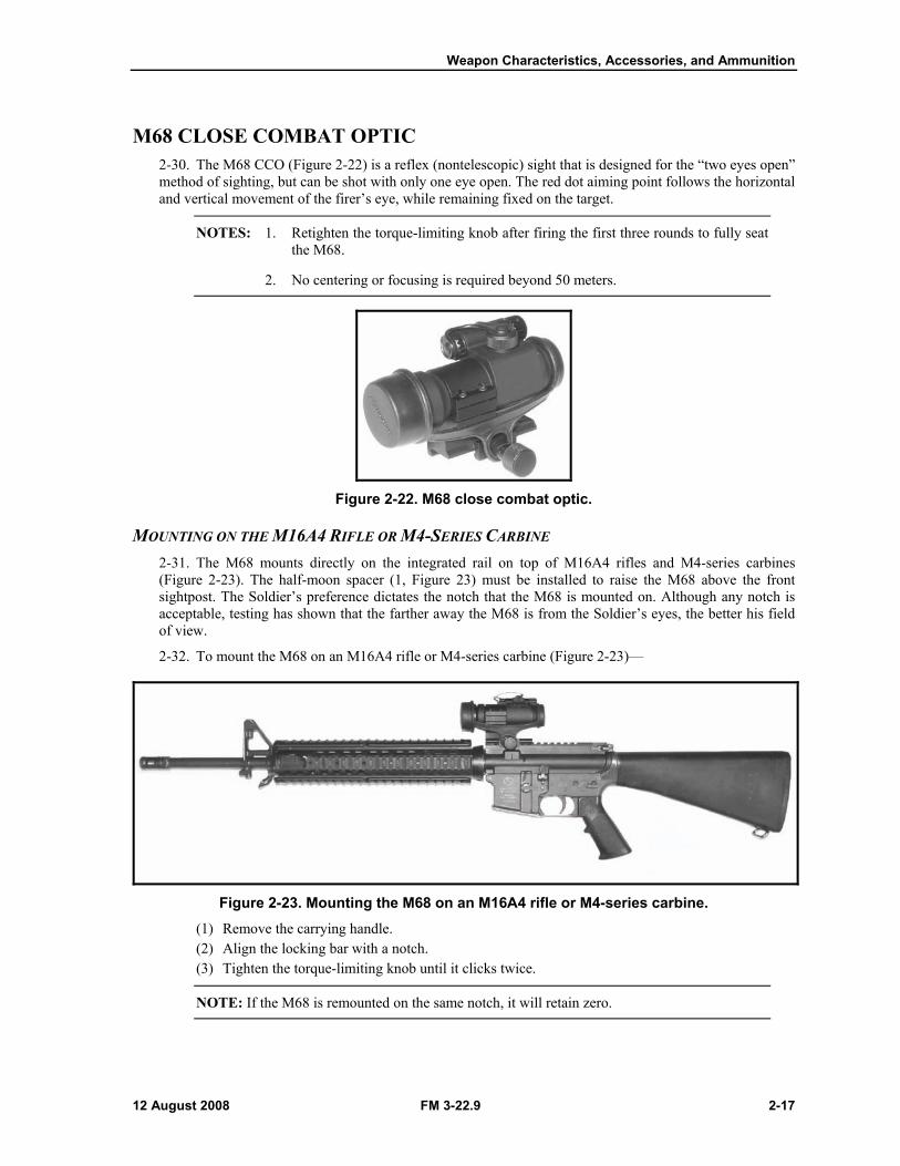
M68 CLOSE COMBAT OPTIC 2-30. The M68 CCO (Figure 2-22) is a reflex (nontelescopic) sight that is designed for the “two eyes open” method of sighting, but can be shot with only one eye open. The red dot aiming point follows the horizontal and vertical movement of the firer’s eye, while remaining fixed on the target.
NOTES: 1. Retighten the torque-limiting knob after firing the first three rounds to fully seat the M68.
2. No centering or focusing is required beyond 50 meters.
Figure 2-22. M68 close combat optic.
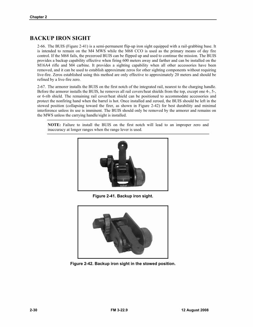
MOUNTING ON THE M16A4 RIFLE OR M4-SERIES CARBINE 2-31. The M68 mounts directly on the integrated rail on top of M16A4 rifles and M4-series carbines (Figure 2-23). The half-moon spacer (1, Figure 23) must be installed to raise the M68 above the front sightpost. The Soldier’s preference dictates the notch that the M68 is mounted on. Although any notch is acceptable, testing has shown that the farther away the M68 is from the Soldier’s eyes, the better his field of view.
2-32. To mount the M68 on an M16A4 rifle or M4-series carbine (Figure 2-23)—
Figure 2-23. Mounting the M68 on an M16A4 rifle or M4-series carbine.
(1) Remove the carrying handle. (2) Align the locking bar with a notch. (3) Tighten the torque-limiting knob until it clicks twice.
NOTE: If the M68 is remounted on the same notch, it will retain zero.
Chapter 2
2-30 FM 3-22.9 12 August 2008
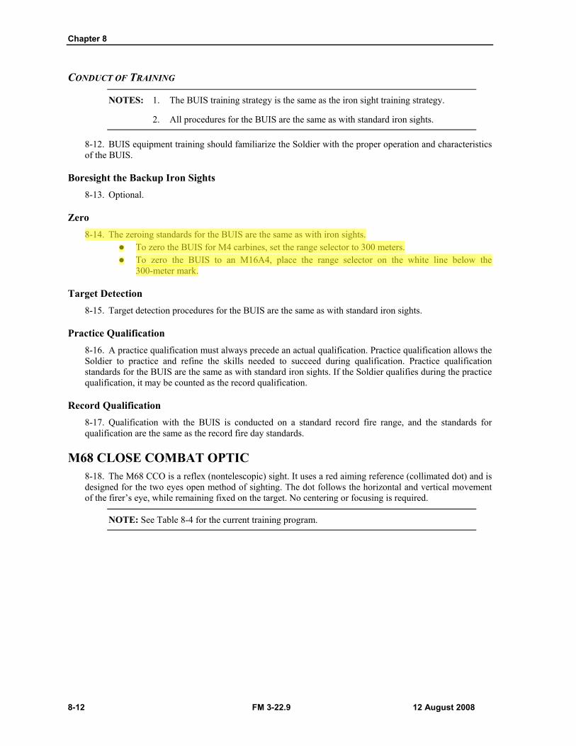
BACKUP IRON SIGHT 2-66. The BUIS (Figure 2-41) is a semi-permanent flip-up iron sight equipped with a rail-grabbing base. It is intended to remain on the M4 MWS while the M68 CCO is used as the primary means of day fire control. If the M68 fails, the prezeroed BUIS can be flipped up and used to continue the mission. The BUIS provides a backup capability effective when firing 600 meters away and farther and can be installed on the M16A4 rifle and M4 carbine. It provides a sighting capability when all other accessories have been removed, and it can be used to establish approximate zeros for other sighting components without requiring live-fire. Zeros established using this method are only effective to approximately 20 meters and should be refined by a live-fire zero.
2-67. The armorer installs the BUIS on the first notch of the integrated rail, nearest to the charging handle. Before the armorer installs the BUIS, he removes all rail covers/heat shields from the top, except one 4-, 5-, or 6-rib shield. The remaining rail cover/heat shield can be positioned to accommodate accessories and protect the nonfiring hand when the barrel is hot. Once installed and zeroed, the BUIS should be left in the stowed position (collapsing toward the firer, as shown in Figure 2-42) for best durability and minimal interference unless its use is imminent. The BUIS should only be removed by the armorer and remains on the MWS unless the carrying handle/sight is installed.
NOTE: Failure to install the BUIS on the first notch will lead to an improper zero and inaccuracy at longer ranges when the range lever is used.
Figure 2-41. Backup iron sight.
Figure 2-42. Backup iron sight in the stowed position.
Chapter 8
8-12 FM 3-22.9 12 August 2008
CONDUCT OF TRAINING
NOTES: 1. The BUIS training strategy is the same as the iron sight training strategy.
2. All procedures for the BUIS are the same as with standard iron sights.
8-12. BUIS equipment training should familiarize the Soldier with the proper operation and characteristics of the BUIS.
Boresight the Backup Iron Sights 8-13. Optional.
Zero 8-14. The zeroing standards for the BUIS are the same as with iron sights.
To zero the BUIS for M4 carbines, set the range selector to 300 meters. To zero the BUIS to an M16A4, place the range selector on the white line below the
300-meter mark.
Target Detection 8-15. Target detection procedures for the BUIS are the same as with standard iron sights.
Practice Qualification 8-16. A practice qualification must always precede an actual qualification. Practice qualification allows the Soldier to practice and refine the skills needed to succeed during qualification. Practice qualification standards for the BUIS are the same as with standard iron sights. If the Soldier qualifies during the practice qualification, it may be counted as the record qualification.
Record Qualification 8-17. Qualification with the BUIS is conducted on a standard record fire range, and the standards for qualification are the same as the record fire day standards.
M68 CLOSE COMBAT OPTIC 8-18. The M68 CCO is a reflex (nontelescopic) sight. It uses a red aiming reference (collimated dot) and is designed for the two eyes open method of sighting. The dot follows the horizontal and vertical movement of the firer’s eye, while remaining fixed on the target. No centering or focusing is required.
NOTE: See Table 8-4 for the current training program.
Weapon Characteristics, Accessories, and Ammunition
12 August 2008 FM 3-22.9 2-31
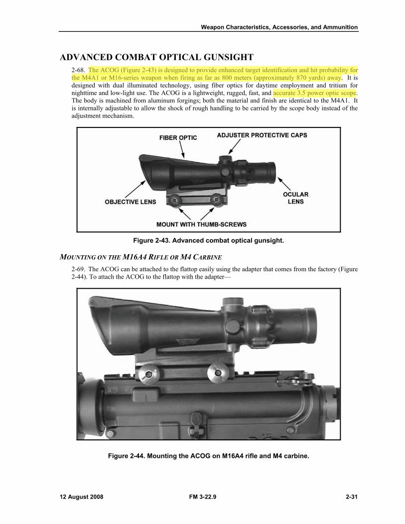
ADVANCED COMBAT OPTICAL GUNSIGHT 2-68. The ACOG (Figure 2-43) is designed to provide enhanced target identification and hit probability for the M4A1 or M16-series weapon when firing as far as 800 meters (approximately 870 yards) away. It is designed with dual illuminated technology, using fiber optics for daytime employment and tritium for nighttime and low-light use. The ACOG is a lightweight, rugged, fast, and accurate 3.5 power optic scope. The body is machined from aluminum forgings; both the material and finish are identical to the M4A1. It is internally adjustable to allow the shock of rough handling to be carried by the scope body instead of the adjustment mechanism.
Figure 2-43. Advanced combat optical gunsight.
MOUNTING ON THE M16A4 RIFLE OR M4 CARBINE 2-69. The ACOG can be attached to the flattop easily using the adapter that comes from the factory (Figure 2-44). To attach the ACOG to the flattop with the adapter—
Figure 2-44. Mounting the ACOG on M16A4 rifle and M4 carbine.
Weapon Characteristics, Accessories, and Ammunition
12 August 2008 FM 3-22.9 2-35
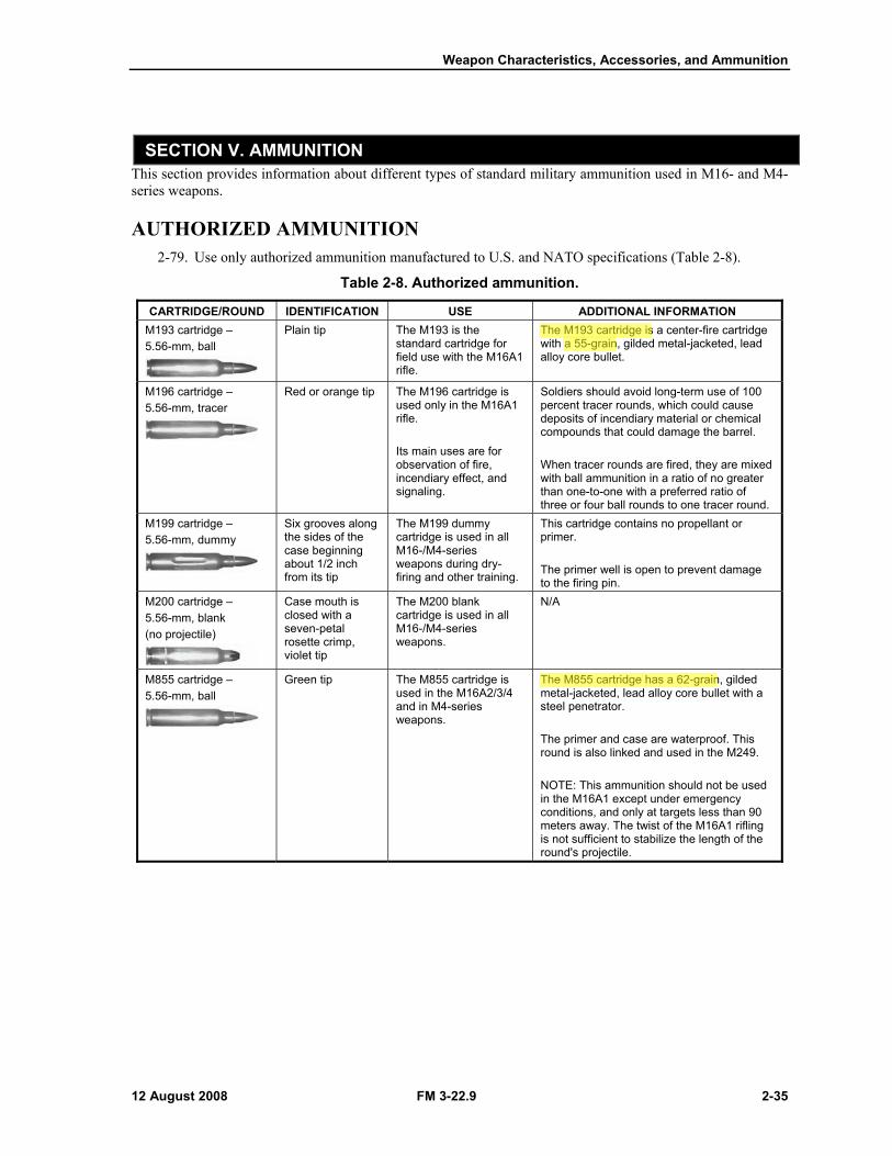
SECTION V. AMMUNITION This section provides information about different types of standard military ammunition used in M16- and M4-series weapons.
AUTHORIZED AMMUNITION 2-79. Use only authorized ammunition manufactured to U.S. and NATO specifications (Table 2-8).
Table 2-8. Authorized ammunition.
CARTRIDGE/ROUND IDENTIFICATION USE ADDITIONAL INFORMATION M193 cartridge – 5.56-mm, ball
Plain tip The M193 is the standard cartridge for field use with the M16A1 rifle.
The M193 cartridge is a center-fire cartridge with a 55-grain, gilded metal-jacketed, lead alloy core bullet.
M196 cartridge – 5.56-mm, tracer
Red or orange tip The M196 cartridge is used only in the M16A1 rifle. Its main uses are for observation of fire, incendiary effect, and signaling.
Soldiers should avoid long-term use of 100 percent tracer rounds, which could cause deposits of incendiary material or chemical compounds that could damage the barrel. When tracer rounds are fired, they are mixed with ball ammunition in a ratio of no greater than one-to-one with a preferred ratio of three or four ball rounds to one tracer round.
M199 cartridge – 5.56-mm, dummy
Six grooves along the sides of the case beginning about 1/2 inch from its tip
The M199 dummy cartridge is used in all M16-/M4-series weapons during dry-firing and other training.
This cartridge contains no propellant or primer. The primer well is open to prevent damage to the firing pin.
M200 cartridge – 5.56-mm, blank (no projectile)
Case mouth is closed with a seven-petal rosette crimp, violet tip
The M200 blank cartridge is used in all M16-/M4-series weapons.
N/A
M855 cartridge – 5.56-mm, ball
Green tip The M855 cartridge is used in the M16A2/3/4 and in M4-series weapons.
The M855 cartridge has a 62-grain, gilded metal-jacketed, lead alloy core bullet with a steel penetrator. The primer and case are waterproof. This round is also linked and used in the M249. NOTE: This ammunition should not be used in the M16A1 except under emergency conditions, and only at targets less than 90 meters away. The twist of the M16A1 rifling is not sufficient to stabilize the length of the round's projectile.
Chapter 2
2-36 FM 3-22.9 12 August 2008
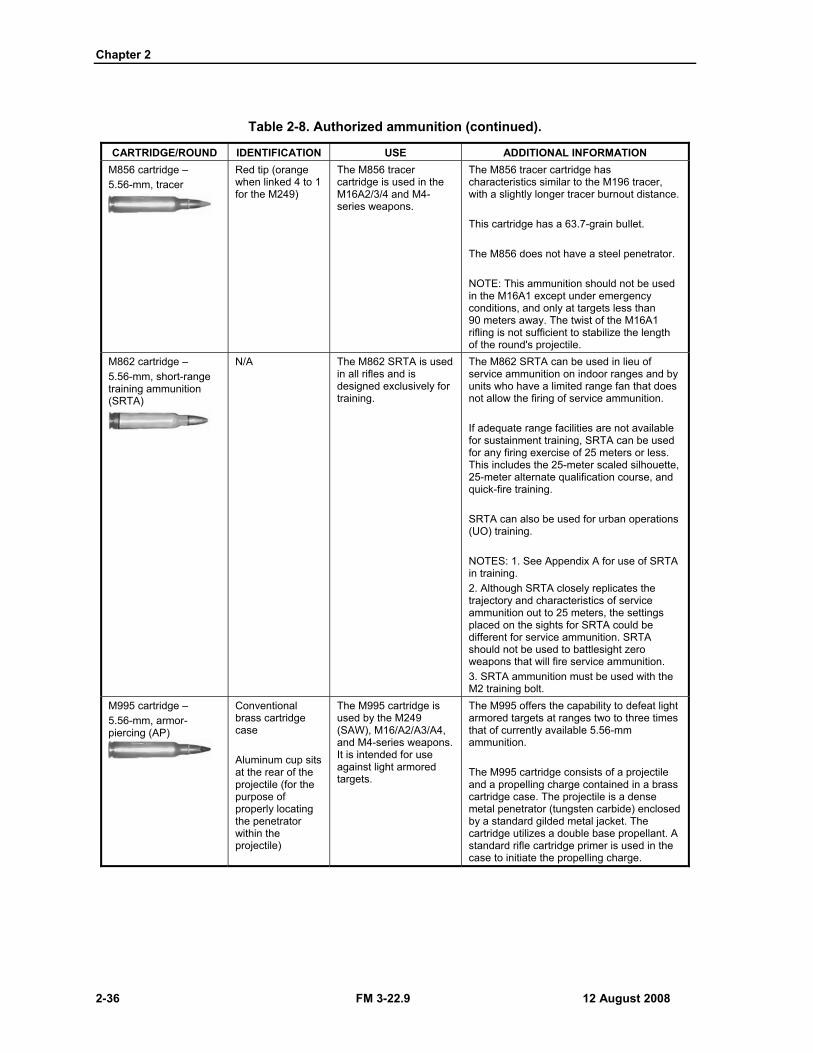
Table 2-8. Authorized ammunition (continued).
CARTRIDGE/ROUND IDENTIFICATION USE ADDITIONAL INFORMATION M856 cartridge – 5.56-mm, tracer
Red tip (orange when linked 4 to 1 for the M249)
The M856 tracer cartridge is used in the M16A2/3/4 and M4-series weapons.
The M856 tracer cartridge has characteristics similar to the M196 tracer, with a slightly longer tracer burnout distance. This cartridge has a 63.7-grain bullet. The M856 does not have a steel penetrator. NOTE: This ammunition should not be used in the M16A1 except under emergency conditions, and only at targets less than 90 meters away. The twist of the M16A1 rifling is not sufficient to stabilize the length of the round's projectile.
M862 cartridge – 5.56-mm, short-range training ammunition (SRTA)
N/A The M862 SRTA is used in all rifles and is designed exclusively for training.
The M862 SRTA can be used in lieu of service ammunition on indoor ranges and by units who have a limited range fan that does not allow the firing of service ammunition. If adequate range facilities are not available for sustainment training, SRTA can be used for any firing exercise of 25 meters or less. This includes the 25-meter scaled silhouette, 25-meter alternate qualification course, and quick-fire training. SRTA can also be used for urban operations (UO) training. NOTES: 1. See Appendix A for use of SRTA in training. 2. Although SRTA closely replicates the trajectory and characteristics of service ammunition out to 25 meters, the settings placed on the sights for SRTA could be different for service ammunition. SRTA should not be used to battlesight zero weapons that will fire service ammunition. 3. SRTA ammunition must be used with the M2 training bolt.
M995 cartridge – 5.56-mm, armor-piercing (AP)
Conventional brass cartridge case Aluminum cup sits at the rear of the projectile (for the purpose of properly locating the penetrator within the projectile)
The M995 cartridge is used by the M249 (SAW), M16/A2/A3/A4, and M4-series weapons. It is intended for use against light armored targets.
The M995 offers the capability to defeat light armored targets at ranges two to three times that of currently available 5.56-mm ammunition. The M995 cartridge consists of a projectile and a propelling charge contained in a brass cartridge case. The projectile is a dense metal penetrator (tungsten carbide) enclosed by a standard gilded metal jacket. The cartridge utilizes a double base propellant. A standard rifle cartridge primer is used in the case to initiate the propelling charge.
Weapon Characteristics, Accessories, and Ammunition
12 August 2008 FM 3-22.9 2-37
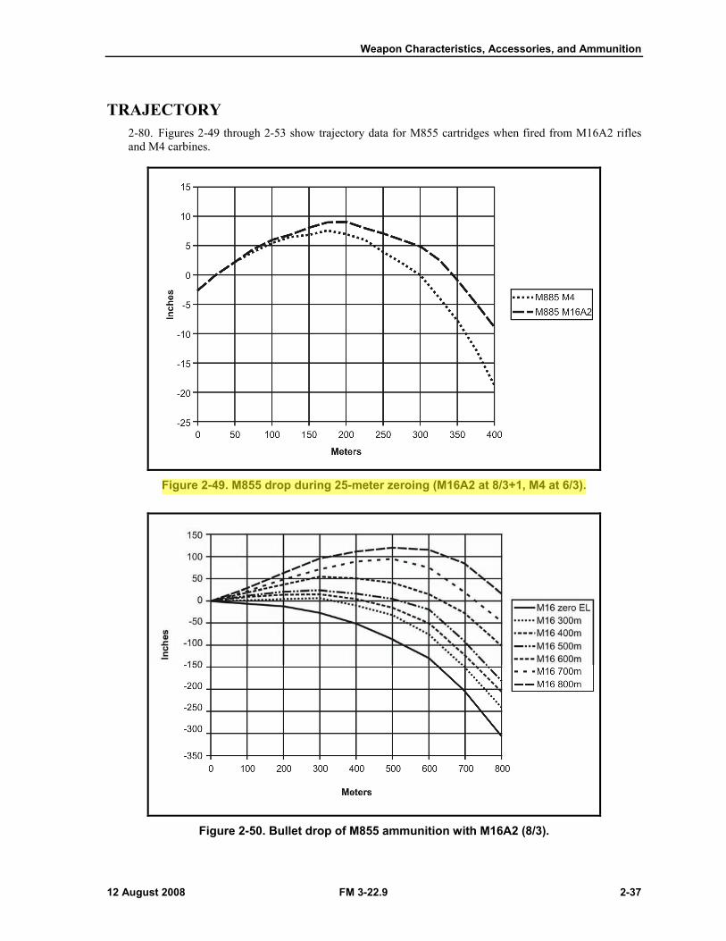
TRAJECTORY 2-80. Figures 2-49 through 2-53 show trajectory data for M855 cartridges when fired from M16A2 rifles and M4 carbines.
Figure 2-49. M855 drop during 25-meter zeroing (M16A2 at 8/3+1, M4 at 6/3).
Figure 2-50. Bullet drop of M855 ammunition with M16A2 (8/3).

Chapter 2
2-38 FM 3-22.9 12 August 2008
Figure 2-51. Bullet drop of M855 ammunition with M4 (6/3).
Figure 2-52. M4 carbine and M16A2 rifle bullet trajectory comparison.
Weapon Characteristics, Accessories, and Ammunition
12 August 2008 FM 3-22.9 2-39
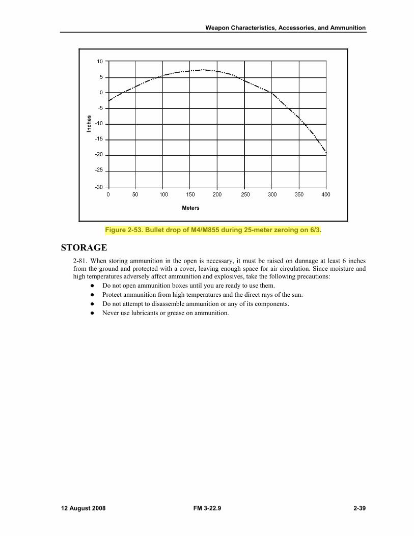
Figure 2-53. Bullet drop of M4/M855 during 25-meter zeroing on 6/3.
STORAGE 2-81. When storing ammunition in the open is necessary, it must be raised on dunnage at least 6 inches from the ground and protected with a cover, leaving enough space for air circulation. Since moisture and high temperatures adversely affect ammunition and explosives, take the following precautions:
Do not open ammunition boxes until you are ready to use them. Protect ammunition from high temperatures and the direct rays of the sun. Do not attempt to disassemble ammunition or any of its components. Never use lubricants or grease on ammunition.
Preliminary Marksmanship Instruction
12 August 2008 FM 3-22.9 4-15
NOTES: 1. Simulators and training devices are listed in Appendix A of this manual.
2. Soldiers who do not meet the standard will receive remedial training before continuing with subsequent instruction.
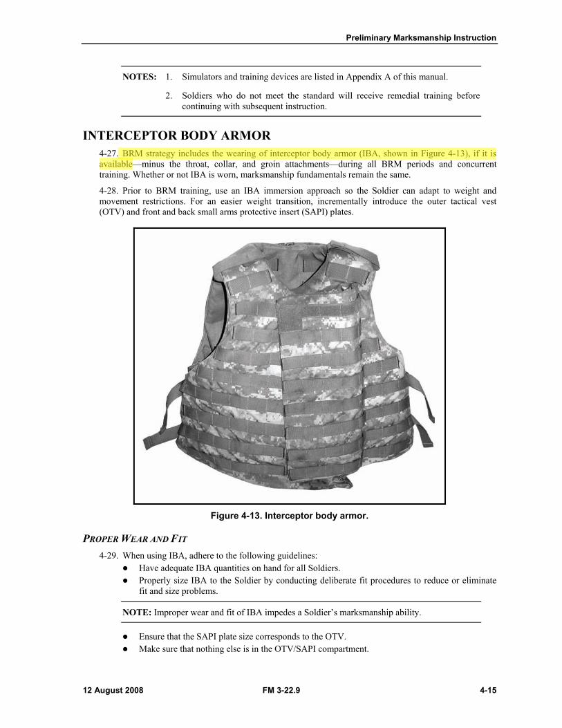
INTERCEPTOR BODY ARMOR 4-27. BRM strategy includes the wearing of interceptor body armor (IBA, shown in Figure 4-13), if it is available—minus the throat, collar, and groin attachments—during all BRM periods and concurrent training. Whether or not IBA is worn, marksmanship fundamentals remain the same.
4-28. Prior to BRM training, use an IBA immersion approach so the Soldier can adapt to weight and movement restrictions. For an easier weight transition, incrementally introduce the outer tactical vest (OTV) and front and back small arms protective insert (SAPI) plates.
Figure 4-13. Interceptor body armor.
PROPER WEAR AND FIT 4-29. When using IBA, adhere to the following guidelines:
Have adequate IBA quantities on hand for all Soldiers. Properly size IBA to the Soldier by conducting deliberate fit procedures to reduce or eliminate
fit and size problems.
NOTE: Improper wear and fit of IBA impedes a Soldier’s marksmanship ability.
Ensure that the SAPI plate size corresponds to the OTV. Make sure that nothing else is in the OTV/SAPI compartment.
Chapter 4
4-16 FM 3-22.9 12 August 2008
WEAR OF HELMETS WITH INTERCEPTOR BODY ARMOR 4-30. When using helmets with IBA, adhere to the following guidelines:
When in the prone position, the IBA's back plate tends to shove the personnel armor system for ground troops (PASGT) helmet over Soldiers’ eyes. To minimize the PASGT helmet positioning problem, make sure that the helmet is properly sized and fitted. Female shooters with long hair will find that wearing their hair in a bun adds material between the IBA and helmet, further forcing the helmet down over their eyes. Encourage female Soldiers to wear a short (chin length) haircut or cornrow hairstyle. If the female Soldier chooses not to wear short hair, allow her to wear her hair down when firing. Tightening the suspension harness and sweat band (raising the helmet higher on the head) can lessen interference with the IBA, hair, and helmet.
The Army combat helmet (ACH) is lighter than the PASGT helmet, has better weight distribution, and contains less material that can impede a Soldier’s firing vision when in the prone position. The ACH does not interfere with the IBA or block a Soldier’s vision while in the prone position.
ADJUSTMENTS TO FIRING POSITIONS 4-31. When using IBA, adhere to the following guidelines:
To increase comfort and stability while wearing IBA in the prone position, scoop sand or dirt underneath the chest while preparing to fire.
To alleviate the pain and pressure on elbows and knees that the added weight of IBA causes, use elbow and knee pads. If used in the kneeling position, do not rest the elbow pad on the knee pad; hard plastic on hard plastic is not conducive to a steady position. To help with stability while firing in the kneeling position, squeeze the rifle buttstock between the SAPI plate and bicep. Loosen the firing-side straps and tighten the nonfiring-side straps to shift the SAPI plate away from the firing side.
Instead of using load-bearing equipment (LBE), attach canteens, ammunition pouches, or first aid pouches directly to the IBA to minimize interference with LBE shoulder straps, IBA, and helmet.
Reserve IBA firing with throat, collar, or groin protectors for ARM. To position themselves more comfortably and be able to reach the handguards, Soldiers of
shorter stature may have to increase their body-line-to-rifle axis angle to more of an “L” shape. Soldiers should be in a comfortable firing position to leverage the natural point of aim. The more
the target and rifle are naturally in line (as when in a relaxed position), the less movement is needed to acquire a proper sight picture.
FOUR FNDAMENTALS 4-32. Before the Soldier approaches the firing line, he must understand and apply the four fundamentals:
Steady position. Aiming. Breath control. Trigger squeeze.
4-33. Soldiers apply these four fundamentals rapidly and consistently to perform the integrated act of firing. These fundamentals should be practiced while the Soldier is wearing all of his equipment, including his helmet and IBA (if available).
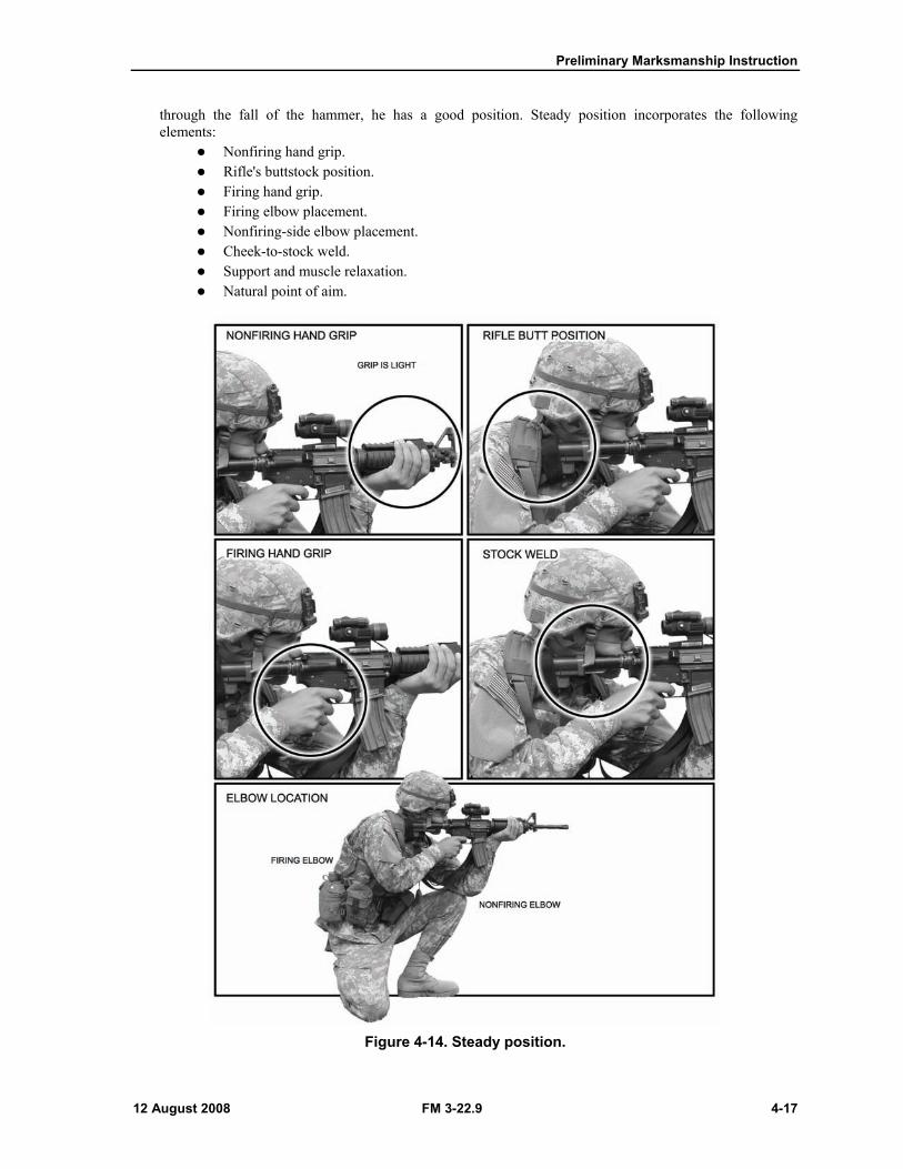
STEADY POSITION 4-34. When the Soldier approaches the firing line, he assumes a comfortable, steady firing position (Figure 4-14). The firer is the best judge of the quality of his position. If he can hold the front sightpost steady
Preliminary Marksmanship Instruction
12 August 2008 FM 3-22.9 4-17
through the fall of the hammer, he has a good position. Steady position incorporates the following elements:
Nonfiring hand grip. Rifle's buttstock position. Firing hand grip. Firing elbow placement. Nonfiring-side elbow placement. Cheek-to-stock weld. Support and muscle relaxation. Natural point of aim.
Figure 4-14. Steady position.
Chapter 4
4-18 FM 3-22.9 12 August 2008
Nonfiring Hand Grip 4-35. The weapon's handguard rests lightly on the heel of the nonfiring hand, in the "V" formed by the thumb and fingers.
Rifle's Buttstock Position 4-36. Place the weapon's buttstock into the pocket of the firing shoulder. When wearing IBA, place the weapon's buttstock where the pocket should be; this reduces the effect of recoil and ensures a steady position.
Firing Hand Grip 4-37. The firing hand grasps the pistol grip so that it fits in the "V" formed by the thumb and forefinger. The forefinger is placed on the trigger so that the lay of the weapon is not disturbed when the trigger is squeezed. The remaining three fingers exert a slight rearward pressure to ensure that the buttstock remains in the pocket of the shoulder.
Firing Elbow Placement 4-38. The firing elbow is important in providing balance. Its exact location depends on the firing or fighting position used. Placement of the firing elbow should allow the firer’s shoulders to remain level.
Nonfiring-Side Elbow Placement 4-39. The nonfiring-side elbow is positioned firmly under the weapon to allow a comfortable and stable position. When the Soldier engages a wide sector of fire, moving targets, and targets at various elevations, his nonfiring-side elbow should remain free from support.
Cheek-to-Stock Weld 4-40. The cheek-to-stock weld should provide a natural line of sight through the center of the rear sight aperture to the front sightpost and onto the target. The firer’s neck should be relaxed, allowing his cheek to fall naturally onto the stock.
NOTE: Proper eye relief is obtained when a Soldier establishes a good cheek-to-stock weld. A small change in eye relief normally occurs each time that the firer assumes a different firing position.
4-41. Through dry-fire training, the Soldier practices this position until he assumes the same cheek-to-stock weld each time he assumes a given position, which provides consistency in aiming. To learn to maintain the same cheek-to-stock weld each time the weapon is aimed, the Soldier should begin by trying to touch the charging handle with his nose when assuming a firing position. The Soldier should be mindful of how the nose touches the charging handle and should be consistent when doing so. This position should be critiqued and reinforced during dry-fire training.
Support and Muscle Relaxation 4-42. When artificial support (for example, sandbags, logs, or stumps) is available, it should be used to steady the position and support the weapon. If support is used properly, the Soldier should be able to relax most of his muscles. If artificial support is not available, the bones—not the muscles—in the firer’s upper body must support the weapon. Using muscles to support the rifle can cause muscle fatigue, which in turn, causes the weapon to move.
Preliminary Marksmanship Instruction
12 August 2008 FM 3-22.9 4-19
Natural Point of Aim 4-43. When the Soldier first assumes his firing position, he orients his weapon in the general direction of his target. Then, he adjusts his body to align the weapon and sights with the desired point of aim. When using proper support and consistent cheek-to-stock weld, the Soldier should have his weapon and sights naturally aligned on the target.
4-44. If correct body-rifle-target alignment cannot be achieved, the front sightpost must be held on the target using muscular support and effort. As the weapon fires, muscles tend to relax, causing the front sight to move away from the target, toward the natural point of aim. Adjusting this natural point of aim to the target eliminates this movement. When multiple target exposures are expected or a sector of fire must be covered, the Soldier adjusts his natural point of aim to the center of the expected target exposure area or sector.
AIMING 4-45. Having mastered the task of holding the rifle steady, the Soldier must align the rifle with the target in exactly the same way for each firing. The firer is the final judge as to where his eye is focused. The instructor or trainer emphasizes this point by having the firer focus on the target and then on the front sightpost. He checks the position of the firing eye to ensure that it is in line with the rear sight aperture. The elements of aiming training are as follows:
Sight alignment. Focus of the eye. Sight picture. Front sightpost. Aiming practice.
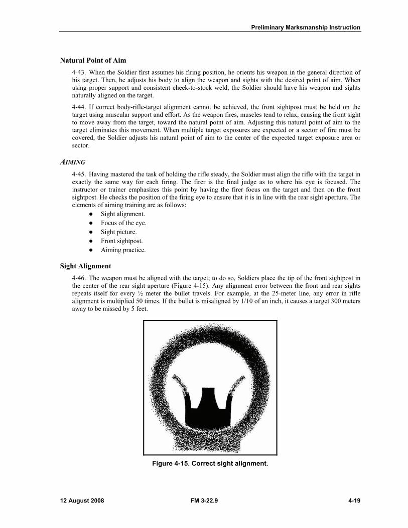
Sight Alignment 4-46. The weapon must be aligned with the target; to do so, Soldiers place the tip of the front sightpost in the center of the rear sight aperture (Figure 4-15). Any alignment error between the front and rear sights repeats itself for every ½ meter the bullet travels. For example, at the 25-meter line, any error in rifle alignment is multiplied 50 times. If the bullet is misaligned by 1/10 of an inch, it causes a target 300 meters away to be missed by 5 feet.
Figure 4-15. Correct sight alignment.
Chapter 4
4-20 FM 3-22.9 12 August 2008
Focus of the Eye 4-47. A proper firing position aligns the eye with the center of the rear sight aperture. When the eye is focused on the front sightpost, the eye's natural ability to center objects in a circle and to seek the point of greatest light (center of the aperture) aid in providing correct sight alignment. For the average Soldier firing at combat-type targets, the eye's natural ability can accurately align the sights. Therefore, the firer can place the tip of the front sightpost on the point of aim, but the eye must be focused on the tip of the front sightpost. This causes the target to appear blurry, while the front sightpost is seen clearly. Two reasons for focusing on the front sightpost are:
(1) Only a minor aiming error should occur, since the error reflects only as much as the Soldier fails to determine the target's center. A greater aiming error can result if the front sightpost is blurry due to focusing on the target or other objects.
(2) Focusing on the tip of the front sightpost aids the firer in maintaining proper sight alignment.
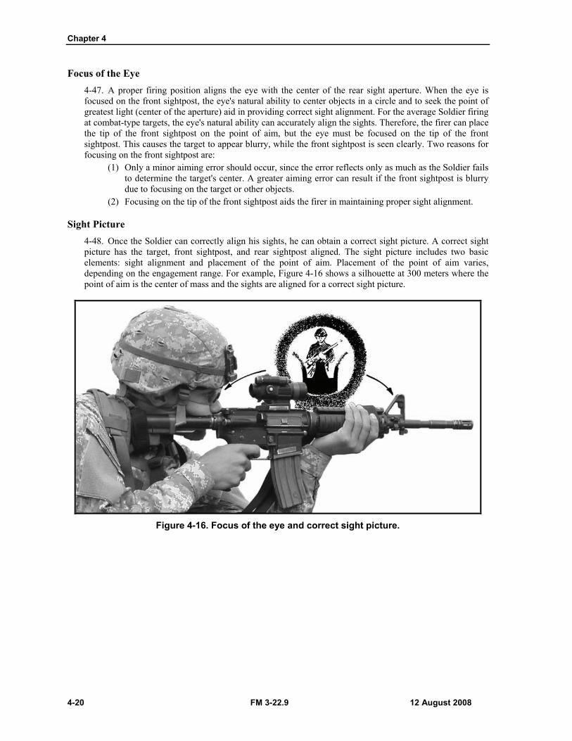
Sight Picture 4-48. Once the Soldier can correctly align his sights, he can obtain a correct sight picture. A correct sight picture has the target, front sightpost, and rear sightpost aligned. The sight picture includes two basic elements: sight alignment and placement of the point of aim. Placement of the point of aim varies, depending on the engagement range. For example, Figure 4-16 shows a silhouette at 300 meters where the point of aim is the center of mass and the sights are aligned for a correct sight picture.
Figure 4-16. Focus of the eye and correct sight picture.
Preliminary Marksmanship Instruction
12 August 2008 FM 3-22.9 4-21
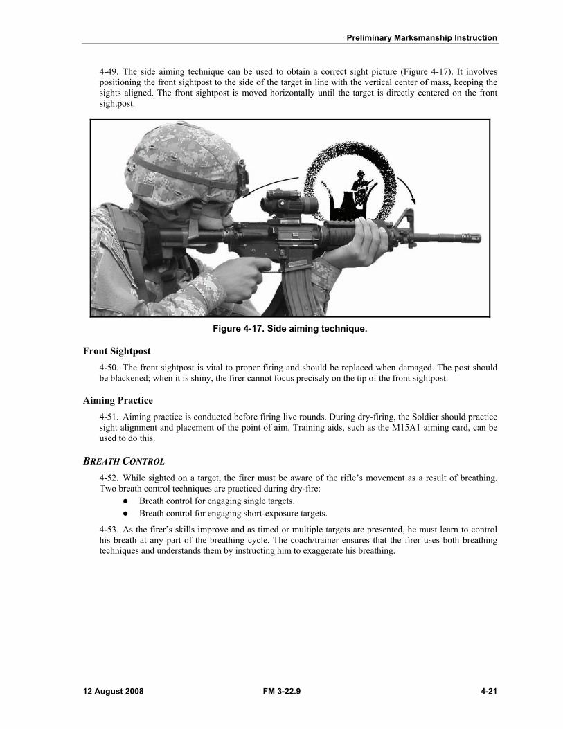
4-49. The side aiming technique can be used to obtain a correct sight picture (Figure 4-17). It involves positioning the front sightpost to the side of the target in line with the vertical center of mass, keeping the sights aligned. The front sightpost is moved horizontally until the target is directly centered on the front sightpost.
Figure 4-17. Side aiming technique.
Front Sightpost 4-50. The front sightpost is vital to proper firing and should be replaced when damaged. The post should be blackened; when it is shiny, the firer cannot focus precisely on the tip of the front sightpost.
Aiming Practice 4-51. Aiming practice is conducted before firing live rounds. During dry-firing, the Soldier should practice sight alignment and placement of the point of aim. Training aids, such as the M15A1 aiming card, can be used to do this.
BREATH CONTROL 4-52. While sighted on a target, the firer must be aware of the rifle’s movement as a result of breathing. Two breath control techniques are practiced during dry-fire:
Breath control for engaging single targets. Breath control for engaging short-exposure targets.
4-53. As the firer’s skills improve and as timed or multiple targets are presented, he must learn to control his breath at any part of the breathing cycle. The coach/trainer ensures that the firer uses both breathing techniques and understands them by instructing him to exaggerate his breathing.
Chapter 4
4-22 FM 3-22.9 12 August 2008
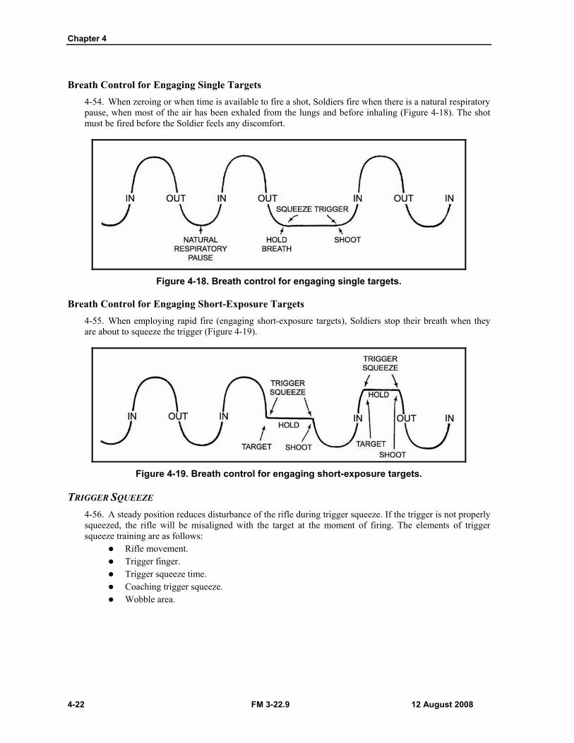
Breath Control for Engaging Single Targets 4-54. When zeroing or when time is available to fire a shot, Soldiers fire when there is a natural respiratory pause, when most of the air has been exhaled from the lungs and before inhaling (Figure 4-18). The shot must be fired before the Soldier feels any discomfort.
Figure 4-18. Breath control for engaging single targets.
Breath Control for Engaging Short-Exposure Targets 4-55. When employing rapid fire (engaging short-exposure targets), Soldiers stop their breath when they are about to squeeze the trigger (Figure 4-19).
Figure 4-19. Breath control for engaging short-exposure targets.
TRIGGER SQUEEZE 4-56. A steady position reduces disturbance of the rifle during trigger squeeze. If the trigger is not properly squeezed, the rifle will be misaligned with the target at the moment of firing. The elements of trigger squeeze training are as follows:
Rifle movement. Trigger finger. Trigger squeeze time. Coaching trigger squeeze. Wobble area.
Preliminary Marksmanship Instruction
12 August 2008 FM 3-22.9 4-23
Rifle Movement 4-57. Trigger squeeze is important for two reasons:
Any sudden movement of the finger on the trigger can disturb the lay of the rifle and cause the shot to miss the target.
The precise instant of firing should be a surprise to the Soldier. If a Soldier knows the exact instant that the rifle will fire, the Soldier will naturally compensate for the weapon's noise and recoil, causing him to miss the target. Soldiers usually tense their shoulders when expecting the rifle to fire; it is difficult to detect since the Soldier does not realize that he is flinching.
Trigger Finger 4-58. The Soldier places his trigger finger (index finger on the firing hand) on the trigger between the first joint and the tip of the finger—not the very end of the finger—and adjusts depending on his hand size and grip. The trigger finger must squeeze the trigger to the rear so the hammer falls without disturbing the lay of the rifle.
4-59. When a live round is fired, it is difficult to see the effect that the trigger pull had on the lay of the rifle. It is important to experiment with many finger positions during dry-fire training to ensure that the hammer is falling with little disturbance to the aiming process.
Trigger Squeeze Time 4-60. The proper trigger squeeze should start with slight pressure on the trigger during the initial aiming process. The firer applies more pressure after the front sightpost is steady on the target and he is holding his breath.
4-61. As the firer’s skills increase with practice, he needs less time spent on trigger squeeze. A novice firer can take five seconds to perform an adequate trigger squeeze, but as skills improve, he can squeeze the trigger in a second or less.
Coaching Trigger Squeeze 4-62. The coach/trainer—
Observes the trigger squeeze, emphasizes the correct procedure, and checks the firer’s applied pressure.
Places his finger on the trigger and has the firer squeeze the trigger by applying pressure to his finger.
Ensures that the firer squeezes straight to the rear on the trigger, avoiding a left or right twisting movement.
Observes that the firer follows through and holds the trigger to the rear for approximately one second after the round has been fired.
Wobble Area 4-63. Wobble area is the movement of the front sight around the point of aim when the rifle is in the steadiest position.
4-64. The position must provide for the smallest possible wobble area. From a supported position, there should be minimal wobble area and little reason to detect
movement. If movement of the rifle causes the front sight to leave the target, more practice is needed.
From an unsupported position, the firer experiences a greater wobble area than from a supported position. If the front sight strays from the target during the firing process, the firer should hold constant pressure on the trigger and resume as soon as he corrects the sighting.
Preliminary Marksmanship Instruction
12 August 2008 FM 3-22.9 4-25
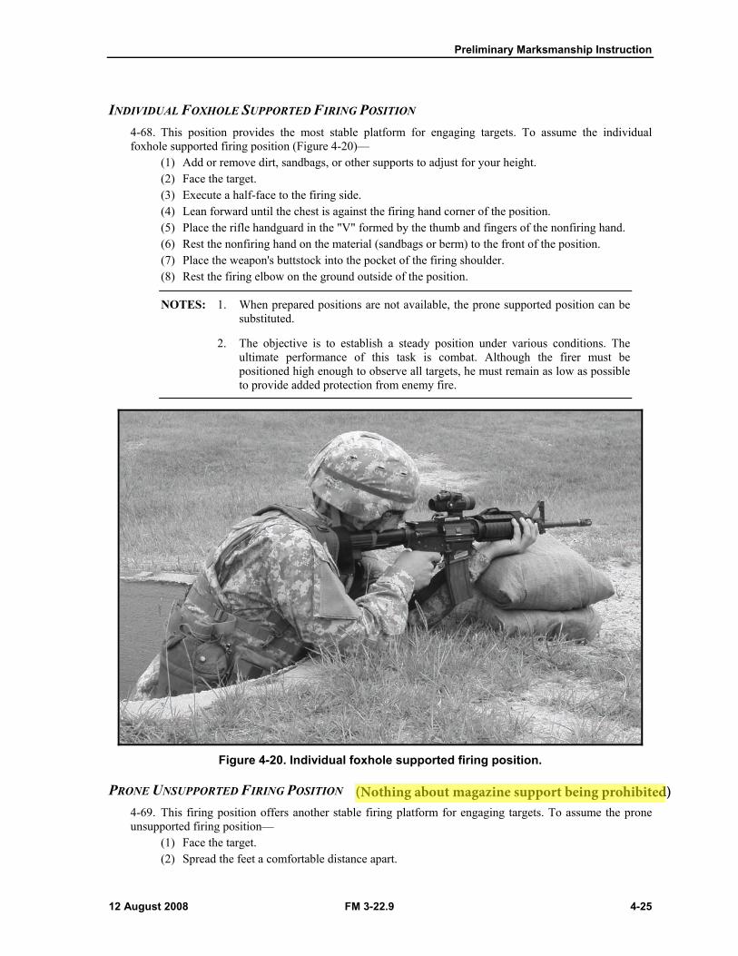
INDIVIDUAL FOXHOLE SUPPORTED FIRING POSITION 4-68. This position provides the most stable platform for engaging targets. To assume the individual foxhole supported firing position (Figure 4-20)—
(1) Add or remove dirt, sandbags, or other supports to adjust for your height. (2) Face the target. (3) Execute a half-face to the firing side. (4) Lean forward until the chest is against the firing hand corner of the position. (5) Place the rifle handguard in the "V" formed by the thumb and fingers of the nonfiring hand. (6) Rest the nonfiring hand on the material (sandbags or berm) to the front of the position. (7) Place the weapon's buttstock into the pocket of the firing shoulder. (8) Rest the firing elbow on the ground outside of the position.
NOTES: 1. When prepared positions are not available, the prone supported position can be substituted.
2. The objective is to establish a steady position under various conditions. Theultimate performance of this task is combat. Although the firer must bepositioned high enough to observe all targets, he must remain as low as possibleto provide added protection from enemy fire.
Figure 4-20. Individual foxhole supported firing position.
PRONE UNSUPPORTED FIRING POSITION 4-69. This firing position offers another stable firing platform for engaging targets. To assume the prone unsupported firing position—
(1) Face the target. (2) Spread the feet a comfortable distance apart.
(Nothing about magazine support being prohibited)
Chapter 4
4-26 FM 3-22.9 12 August 2008
(3) Drop to the knees, breaking the fall with the weapon's buttstock. (4) Using the rifle's buttstock as a pivot, roll onto the nonfiring side, placing the nonfiring-side
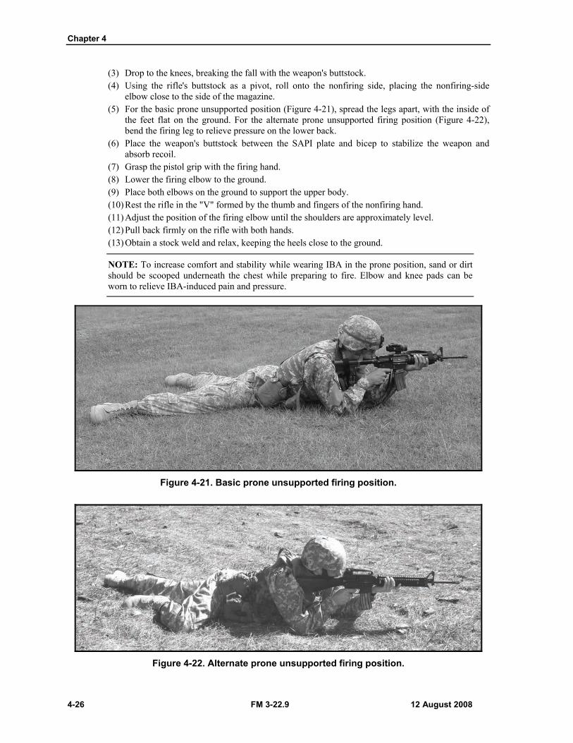
elbow close to the side of the magazine. (5) For the basic prone unsupported position (Figure 4-21), spread the legs apart, with the inside of
the feet flat on the ground. For the alternate prone unsupported firing position (Figure 4-22), bend the firing leg to relieve pressure on the lower back.
(6) Place the weapon's buttstock between the SAPI plate and bicep to stabilize the weapon and absorb recoil.
(7) Grasp the pistol grip with the firing hand. (8) Lower the firing elbow to the ground. (9) Place both elbows on the ground to support the upper body. (10) Rest the rifle in the "V" formed by the thumb and fingers of the nonfiring hand. (11) Adjust the position of the firing elbow until the shoulders are approximately level. (12) Pull back firmly on the rifle with both hands. (13) Obtain a stock weld and relax, keeping the heels close to the ground.
NOTE: To increase comfort and stability while wearing IBA in the prone position, sand or dirt should be scooped underneath the chest while preparing to fire. Elbow and knee pads can be worn to relieve IBA-induced pain and pressure.
Figure 4-21. Basic prone unsupported firing position.
Figure 4-22. Alternate prone unsupported firing position.
Preliminary Marksmanship Instruction
12 August 2008 FM 3-22.9 4-27
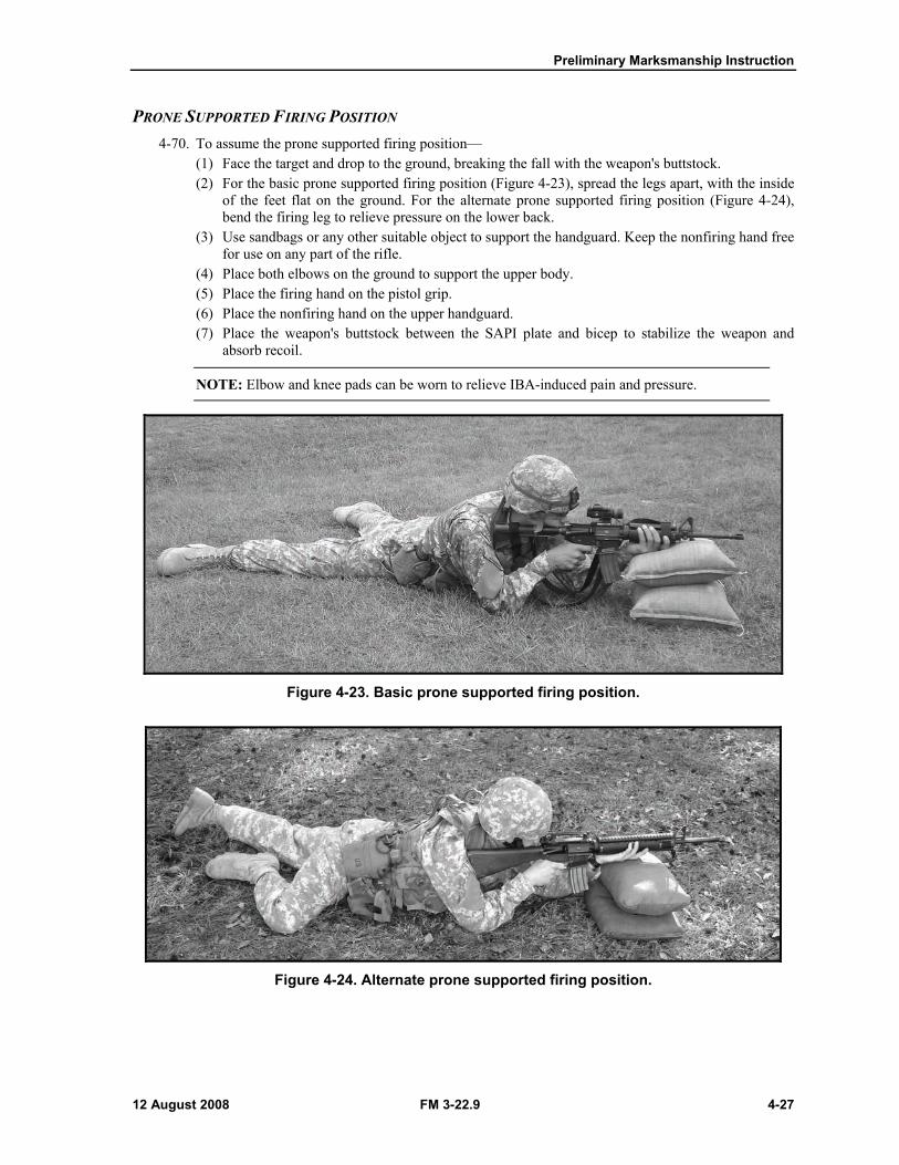
PRONE SUPPORTED FIRING POSITION 4-70. To assume the prone supported firing position—
(1) Face the target and drop to the ground, breaking the fall with the weapon's buttstock. (2) For the basic prone supported firing position (Figure 4-23), spread the legs apart, with the inside
of the feet flat on the ground. For the alternate prone supported firing position (Figure 4-24), bend the firing leg to relieve pressure on the lower back.
(3) Use sandbags or any other suitable object to support the handguard. Keep the nonfiring hand free for use on any part of the rifle.
(4) Place both elbows on the ground to support the upper body. (5) Place the firing hand on the pistol grip. (6) Place the nonfiring hand on the upper handguard. (7) Place the weapon's buttstock between the SAPI plate and bicep to stabilize the weapon and
absorb recoil.
NOTE: Elbow and knee pads can be worn to relieve IBA-induced pain and pressure.
Figure 4-23. Basic prone supported firing position.
Figure 4-24. Alternate prone supported firing position.
Chapter 4
4-28 FM 3-22.9 12 August 2008
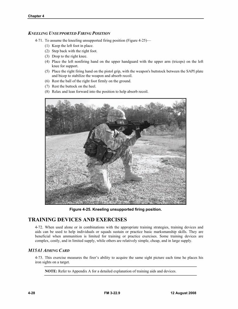
KNEELING UNSUPPORTED FIRING POSITION 4-71. To assume the kneeling unsupported firing position (Figure 4-25)—
(1) Keep the left foot in place. (2) Step back with the right foot. (3) Drop to the right knee. (4) Place the left nonfiring hand on the upper handguard with the upper arm (triceps) on the left
knee for support. (5) Place the right firing hand on the pistol grip, with the weapon's buttstock between the SAPI plate
and bicep to stabilize the weapon and absorb recoil. (6) Rest the ball of the right foot firmly on the ground. (7) Rest the buttock on the heel. (8) Relax and lean forward into the position to help absorb recoil.
Figure 4-25. Kneeling unsupported firing position.
TRAINING DEVICES AND EXERCISES 4-72. When used alone or in combinations with the appropriate training strategies, training devices and aids can be used to help individuals or squads sustain or practice basic marksmanship skills. They are beneficial when ammunition is limited for training or practice exercises. Some training devices are complex, costly, and in limited supply, while others are relatively simple, cheap, and in large supply.
M15A1 AIMING CARD 4-73. This exercise measures the firer’s ability to acquire the same sight picture each time he places his iron sights on a target.
NOTE: Refer to Appendix A for a detailed explanation of training aids and devices.
Chapter 5
5-2 FM 3-22.9 12 August 2008
CONCEPT 5-1. Shot grouping is a form of practice firing with two primary objectives: firing tight shot groups and consistently placing those groups in the same location. Grouping exercises can be conducted anywhere that provides precise location of bullet hits and misses, such as a 25-meter live-fire zeroing range, KD range, EST 2000, LMTS, or location of misses and hits (LOMAH) system.
NOTES: 1. Shot grouping should be conducted between dry-fire training and zeroing.
2. The initial live-fire training should be a grouping exercise with the purpose of practicing and refining marksmanship fundamentals.
ORGANIZATION OF A 25-METER GROUPING RANGE 5-2. The organization and conduct of a grouping range are based on the availability of ammunition, number of personnel, and the firing ability of personnel in training.
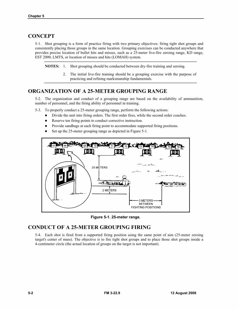
5-3. To properly conduct a 25-meter grouping range, perform the following actions: Divide the unit into firing orders. The first order fires, while the second order coaches. Reserve ten firing points to conduct corrective instruction. Provide sandbags at each firing point to accommodate supported firing positions. Set up the 25-meter grouping range as depicted in Figure 5-1.
Figure 5-1. 25-meter range.
CONDUCT OF A 25-METER GROUPING FIRING 5-4. Each shot is fired from a supported firing position using the same point of aim (25-meter zeroing target's center of mass). The objective is to fire tight shot groups and to place those shot groups inside a 4-centimeter circle (the actual location of groups on the target is not important).
Downrange Feedback
10 February 2011 FM 3-22.9, C1 5-3
NOTES: 1. Since this is not a zeroing exercise, few sight adjustments are made unless the shot group is off of or barely on the 25-meter zeroing target.
2. No sight adjustments should be made until the firer can shoot six consecutive shots (two shot groups) inside a 4-centimeter circle. Once this is accomplished, the Soldier is ready to conduct zeroing procedures.
5-5. To conduct a 25-meter grouping firing—
NOTE: Before beginning the 25-meter grouping firing, each Soldier ensures that his sights are set for 25-meter firing.
(1) The Soldier fires a three-round shot group at the 25-meter zeroing target.
*NOTE: During IET, Soldiers fire three 5-round shot groups at the 25-meter zeroing target. To achieve the standard, 8 out of 10 rounds in two consecutive shot groups must hit within a 4-cm circle.
(2) The firing line is cleared, and the Soldier and coach move downrange to examine the shot group for fundamental errors, triangulate the shot group, and put the number 1 in the center of the shot group (Figures 5-2 and 5-3).
NOTE: If the shot group is off of the 25-meter zeroing target, the Soldier should mechanically zero the weapon. If the shot group is barely on the target, the Soldier should make a bold adjustment.
*(3) The Soldier returns to the firing line and fires a second shot group. (4) The firing line is cleared, and the Soldier moves downrange to examine the second shot group,
triangulate, and mark the center of the shot group with the number 2. (5) The Soldier groups the two shot groups and marks the center.
*5-6. The Soldier repeats Steps 1 through 5 until he places six out of six consecutive rounds inside a 4-centimeter circle. If the Soldier has not grouped with the rounds allotted, he should be removed from the firing line and given remedial training before attempting to group again.
*NOTE: Grouping standard for IET: Group an M16 Series Rifle/M4 Carbine on a 25m zero target by achieving 8 out of 10 rounds in two consecutive five-round shot groups within a 4cm circle within 10 rounds.
NOTE: To be counted, the majority of the round must be inside of the circle.
*5-7. Once the Soldier has demonstrated firing proficiency from the supported firing position, grouping exercises can be conducted from the unsupported firing position.
SHOT GROUP MARKING 5-8. If the Soldier is to benefit from this exercise and if the instructor/trainer (or coach) is to provide useful guidance, the Soldier must mark each shot group for a clear record of his firing practice. The instructor/trainer must understand how to analyze shot groups correctly.
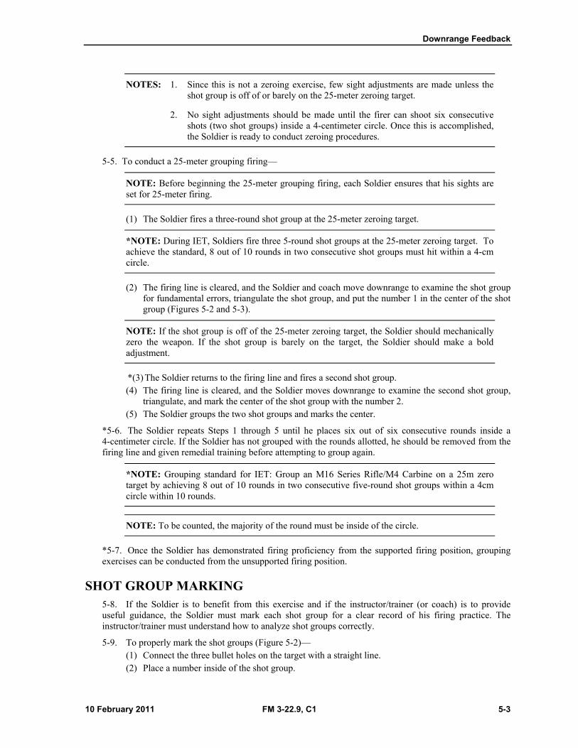
5-9. To properly mark the shot groups (Figure 5-2)— (1) Connect the three bullet holes on the target with a straight line. (2) Place a number inside of the shot group.
Chapter 5
5-4 FM 3-22.9, C1 10 February 2011
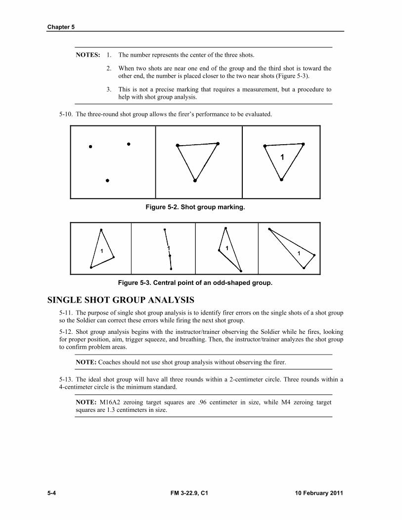
NOTES: 1. The number represents the center of the three shots.
2. When two shots are near one end of the group and the third shot is toward the other end, the number is placed closer to the two near shots (Figure 5-3).
3. This is not a precise marking that requires a measurement, but a procedure to help with shot group analysis.
5-10. The three-round shot group allows the firer’s performance to be evaluated.
Figure 5-2. Shot group marking.
Figure 5-3. Central point of an odd-shaped group.
SINGLE SHOT GROUP ANALYSIS 5-11. The purpose of single shot group analysis is to identify firer errors on the single shots of a shot group so the Soldier can correct these errors while firing the next shot group.
5-12. Shot group analysis begins with the instructor/trainer observing the Soldier while he fires, looking for proper position, aim, trigger squeeze, and breathing. Then, the instructor/trainer analyzes the shot group to confirm problem areas.
NOTE: Coaches should not use shot group analysis without observing the firer.
5-13. The ideal shot group will have all three rounds within a 2-centimeter circle. Three rounds within a 4-centimeter circle is the minimum standard.
NOTE: M16A2 zeroing target squares are .96 centimeter in size, while M4 zeroing target squares are 1.3 centimeters in size.
Downrange Feedback
12 August 2008 FM 3-22.9 5-5
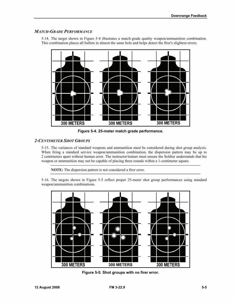
MATCH-GRADE PERFORMANCE 5-14. The target shown in Figure 5-4 illustrates a match-grade quality weapon/ammunition combination. This combination places all bullets in almost the same hole and helps detect the firer's slightest errors.
Figure 5-4. 25-meter match grade performance.
2-CENTIMETER SHOT GROUPS 5-15. The variances of standard weapons and ammunition must be considered during shot group analysis. When firing a standard service weapon/ammunition combination, the dispersion pattern may be up to 2 centimeters apart without human error. The instructor/trainer must ensure the Soldier understands that his weapon or ammunition may not be capable of placing three rounds within a 1-centimeter square.
NOTE: The dispersion pattern is not considered a firer error.
5-16. The targets shown in Figure 5-5 reflect proper 25-meter shot group performances using standard weapon/ammunition combinations.
Figure 5-5. Shot groups with no firer error.
Chapter 5
5-6 FM 3-22.9 12 August 2008
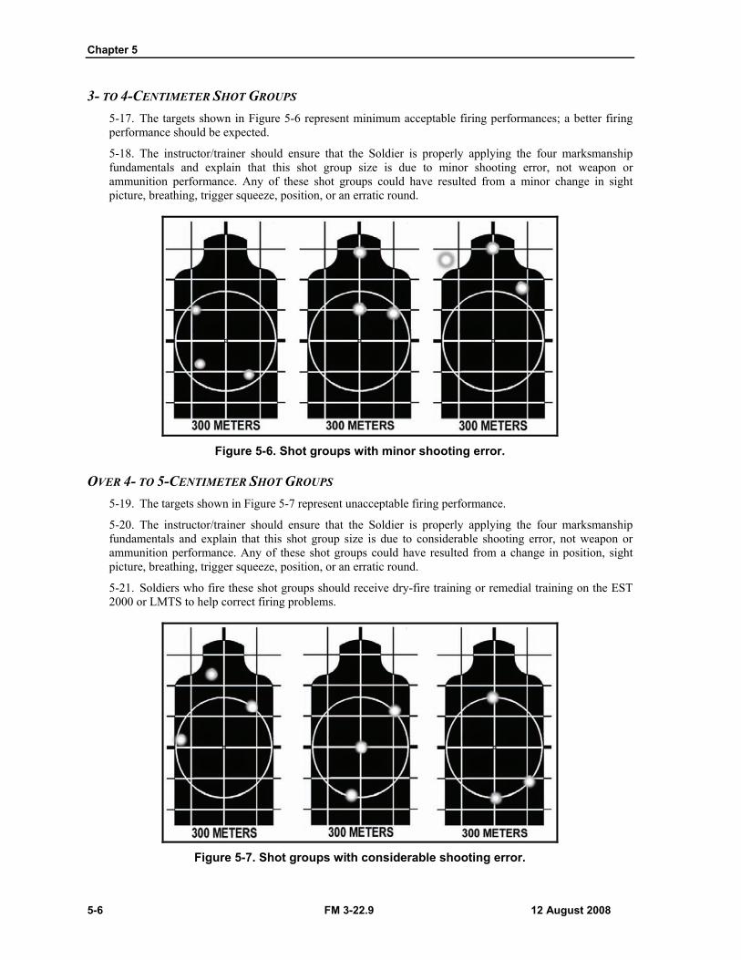
3- TO 4-CENTIMETER SHOT GROUPS 5-17. The targets shown in Figure 5-6 represent minimum acceptable firing performances; a better firing performance should be expected.
5-18. The instructor/trainer should ensure that the Soldier is properly applying the four marksmanship fundamentals and explain that this shot group size is due to minor shooting error, not weapon or ammunition performance. Any of these shot groups could have resulted from a minor change in sight picture, breathing, trigger squeeze, position, or an erratic round.
Figure 5-6. Shot groups with minor shooting error.
OVER 4- TO 5-CENTIMETER SHOT GROUPS 5-19. The targets shown in Figure 5-7 represent unacceptable firing performance.
5-20. The instructor/trainer should ensure that the Soldier is properly applying the four marksmanship fundamentals and explain that this shot group size is due to considerable shooting error, not weapon or ammunition performance. Any of these shot groups could have resulted from a change in position, sight picture, breathing, trigger squeeze, position, or an erratic round.
5-21. Soldiers who fire these shot groups should receive dry-fire training or remedial training on the EST 2000 or LMTS to help correct firing problems.
Figure 5-7. Shot groups with considerable shooting error.
Downrange Feedback
12 August 2008 FM 3-22.9 5-7
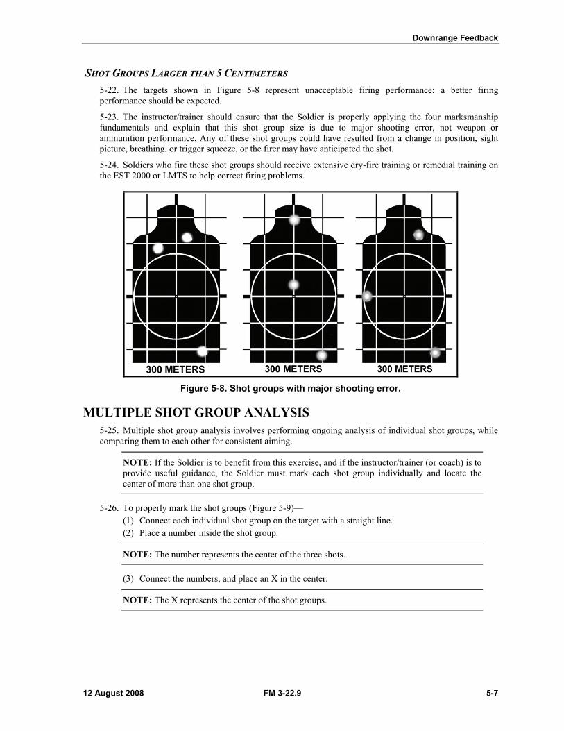
SHOT GROUPS LARGER THAN 5 CENTIMETERS 5-22. The targets shown in Figure 5-8 represent unacceptable firing performance; a better firing performance should be expected.
5-23. The instructor/trainer should ensure that the Soldier is properly applying the four marksmanship fundamentals and explain that this shot group size is due to major shooting error, not weapon or ammunition performance. Any of these shot groups could have resulted from a change in position, sight picture, breathing, or trigger squeeze, or the firer may have anticipated the shot.
5-24. Soldiers who fire these shot groups should receive extensive dry-fire training or remedial training on the EST 2000 or LMTS to help correct firing problems.
Figure 5-8. Shot groups with major shooting error.
MULTIPLE SHOT GROUP ANALYSIS 5-25. Multiple shot group analysis involves performing ongoing analysis of individual shot groups, while comparing them to each other for consistent aiming.
NOTE: If the Soldier is to benefit from this exercise, and if the instructor/trainer (or coach) is to provide useful guidance, the Soldier must mark each shot group individually and locate the center of more than one shot group.
5-26. To properly mark the shot groups (Figure 5-9)— (1) Connect each individual shot group on the target with a straight line. (2) Place a number inside the shot group.
NOTE: The number represents the center of the three shots.
(3) Connect the numbers, and place an X in the center.
NOTE: The X represents the center of the shot groups.
Chapter 5
5-8 FM 3-22.9 12 August 2008
Figure 5-9. Central point of three shot groups.
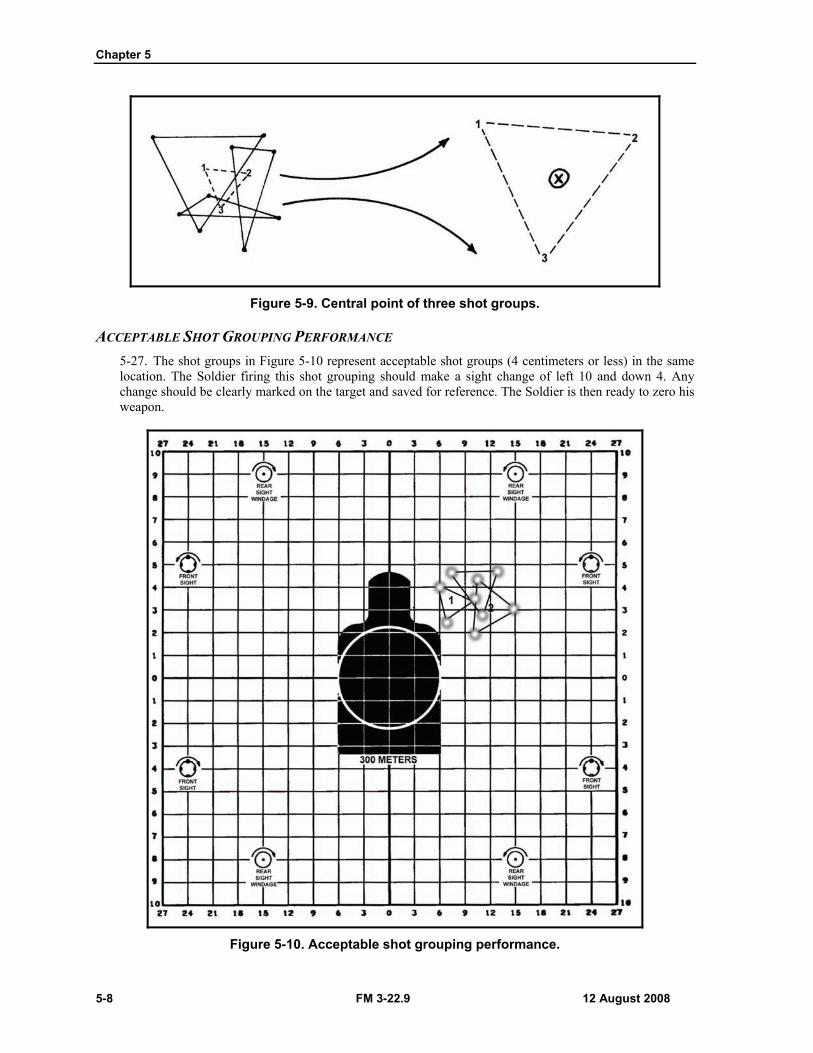
ACCEPTABLE SHOT GROUPING PERFORMANCE 5-27. The shot groups in Figure 5-10 represent acceptable shot groups (4 centimeters or less) in the same location. The Soldier firing this shot grouping should make a sight change of left 10 and down 4. Any change should be clearly marked on the target and saved for reference. The Soldier is then ready to zero his weapon.
Figure 5-10. Acceptable shot grouping performance.
Downrange Feedback
12 August 2008 FM 3-22.9 5-9
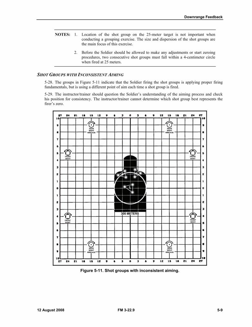
NOTES: 1. Location of the shot group on the 25-meter target is not important when conducting a grouping exercise. The size and dispersion of the shot groups are the main focus of this exercise.
2. Before the Soldier should be allowed to make any adjustments or start zeroing procedures, two consecutive shot groups must fall within a 4-centimeter circle when fired at 25 meters.
SHOT GROUPS WITH INCONSISTENT AIMING 5-28. The groups in Figure 5-11 indicate that the Soldier firing the shot groups is applying proper firing fundamentals, but is using a different point of aim each time a shot group is fired.
5-29. The instructor/trainer should question the Soldier’s understanding of the aiming process and check his position for consistency. The instructor/trainer cannot determine which shot group best represents the firer’s zero.
Figure 5-11. Shot groups with inconsistent aiming.
Chapter 5
5-10 FM 3-22.9 12 August 2008
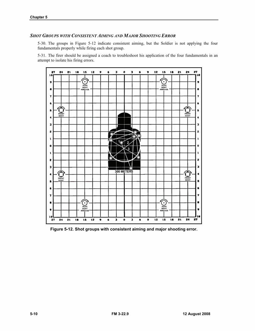
SHOT GROUPS WITH CONSISTENT AIMING AND MAJOR SHOOTING ERROR 5-30. The groups in Figure 5-12 indicate consistent aiming, but the Soldier is not applying the four fundamentals properly while firing each shot group.
5-31. The firer should be assigned a coach to troubleshoot his application of the four fundamentals in an attempt to isolate his firing errors.
Figure 5-12. Shot groups with consistent aiming and major shooting error.
Downrange Feedback
12 August 2008 FM 3-22.9 5-11
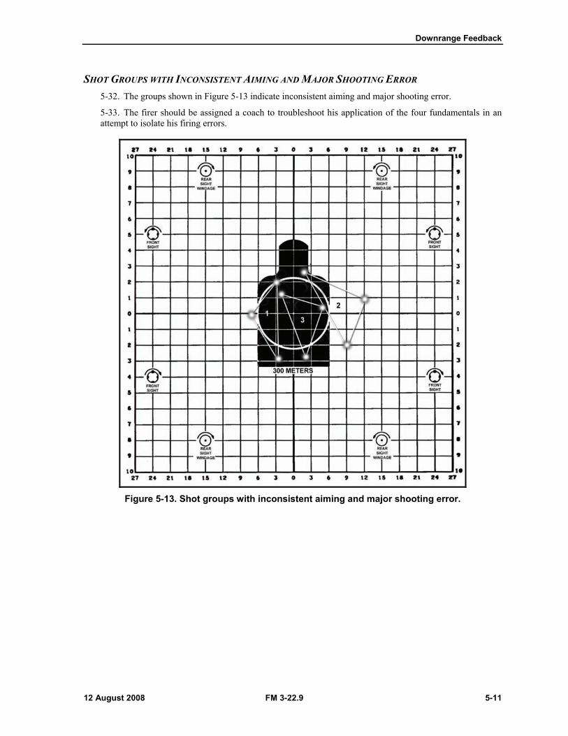
SHOT GROUPS WITH INCONSISTENT AIMING AND MAJOR SHOOTING ERROR 5-32. The groups shown in Figure 5-13 indicate inconsistent aiming and major shooting error.
5-33. The firer should be assigned a coach to troubleshoot his application of the four fundamentals in an attempt to isolate his firing errors.
Figure 5-13. Shot groups with inconsistent aiming and major shooting error.

Chapter 5
5-12 FM 3-22.9 12 August 2008
SHOT GROUPS WITH IMPROPER VERTICAL PLACEMENT 5-34. When viewed as nine shots, the shot groups shown in Figure 5-14 reflect proper horizontal placement of shots, but unsatisfactory vertical dispersion. This indicates a failure to vertically aim at the target's center of mass for each shot.
5-35. The instructor/trainer should check the Soldier’s aiming procedure and adherence to marksmanship fundamentals.
Figure 5-14. Shot groups with improper vertical placement.
Downrange Feedback
12 August 2008 FM 3-22.9 5-13
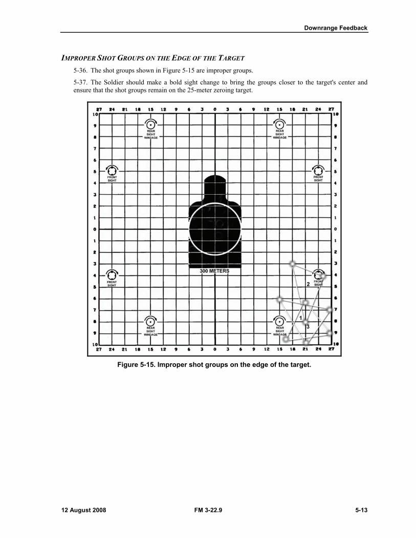
IMPROPER SHOT GROUPS ON THE EDGE OF THE TARGET 5-36. The shot groups shown in Figure 5-15 are improper groups.
5-37. The Soldier should make a bold sight change to bring the groups closer to the target's center and ensure that the shot groups remain on the 25-meter zeroing target.
Figure 5-15. Improper shot groups on the edge of the target.
Chapter 5
5-14 FM 3-22.9 12 August 2008
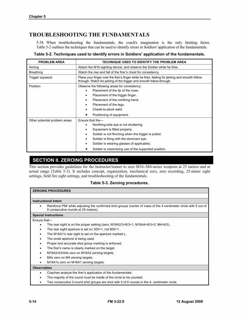
TROUBLESHOOTING THE FUNDAMENTALS 5-38. When troubleshooting the fundamentals, the coach's imagination is the only limiting factor. Table 5-2 outlines the techniques that can be used to identify errors in Soldiers' application of the fundamentals.
Table 5-2. Techniques used to identify errors in Soldiers' application of the fundamentals.
PROBLEM AREA TECHNIQUE USED TO IDENTIFY THE PROBLEM AREA Aiming Attach the M16 sighting device, and observe the Soldier while he fires. Breathing Watch the rise and fall of the firer’s chest for consistency. Trigger squeeze Place your finger over the firer’s finger while he fires, feeling for jerking and smooth follow-
through. Watch for jerking of the trigger and smooth follow-through. Position Observe the following areas for consistency:
• Placement of the tip of the nose. • Placement of the trigger finger. • Placement of the nonfiring hand. • Placement of the legs. • Cheek-to-stock weld.
• Positioning of equipment. Other potential problem areas Ensure that the—
• Nonfiring-side eye is not shuttering. • Equipment is fitted properly. • Soldier is not flinching when the trigger is pulled. • Soldier is firing with the dominant eye. • Soldier is wearing glasses (if applicable).
• Soldier is maximizing use of the supported position.
SECTION II. ZEROING PROCEDURES This section provides guidelines for the instructor/trainer to zero M16-/M4-series weapons at 25 meters and at actual range (Table 5-3). It includes concept, organization, mechanical zero, zero recording, 25-meter sight settings, field fire sight settings, and troubleshooting of the fundamentals.
Table 5-3. Zeroing procedures.
ZEROING PROCEDURES Instructional Intent
• Reinforce PMI while adjusting the confirmed shot groups (center of mass of the 4-centimeter circle with 5 out of 6 consecutive rounds at 25 meters).
Special Instructions Ensure that—
• The rear sight is on the proper setting (zero; M16A2/3=8/3+1; M16A4=6/3+2; M4=6/3). • The rear sight aperture is set on 300+1, not 800+1. • The M16A1's rear sight is set on the aperture marked L. • The small aperture is being used. • Proper and accurate shot group marking is enforced. • The firer's name is clearly marked on the target. • M16A2/A3/A4s zero on M16A2 zeroing targets. • M4s zero on M4 zeroing targets. • M16A1s zero on M16A1 zeroing targets.
Observables • Coaches analyze the firer’s application of the fundamentals. • The majority of the round must be inside of the circle to be counted. • Two consecutive 3-round shot groups are shot with 5 of 6 rounds in the 4- centimeter circle.
Downrange Feedback
12 August 2008 FM 3-22.9 5-15
PURPOSE 5-39. The purpose of battlesight zeroing is to align the sights with the weapon’s barrel given standard issue ammunition. When this is accomplished correctly, the point of aim and point of impact are the same at a given range (250 meters for the M16A1, 300 meters for the M16A2/A3/A4 and M4-series weapons). This sight setting provides the highest hit probability for most combat targets with minimum adjustment to the point of aim.
5-40. When standard zeroing procedures are followed, a properly zeroed weapon for one Soldier is close to the zero for another Soldier. When a straight line is drawn from the target's center to the tip of the front sightpost and through the center of the rear aperture, it makes little difference whose eye is looking along this line. There are many subtle factors that result in differences among individual zeros. Instructors/trainers should emphasize the similarity of individual zeros instead of the differences.
5-41. Most firers can fire with the same zeroed weapon if they properly apply marksmanship fundamentals. This information can be useful in three ways:
(1) If a Soldier has difficulty zeroing and the problem cannot be diagnosed, a good firer could zero the weapon to find the problem and eliminate the weapon as part of the problem.
(2) When a Soldier must fire another Soldier’s weapon without opportunity to verify the zero by firing for example, picking up another man’s weapon on the battlefield), the weapon will be closer to actual zero if the sights are left unchanged. This information is useful in deciding initial sight settings and recording zeros.
(3) All weapons in the arms room, even those not assigned, should have been previously zeroed by the last Soldier they were assigned to. Zeroing this newly assigned weapon should start with the sights left where they are.
SIGHT VARIANCE 5-42. There is no relationship between the specific sight settings a Soldier uses on his weapon to the sight settings he would use to zero another weapon, which makes it essential that each Soldier zeros the weapon that he is assigned. For example, a Soldier could zero his assigned weapon 10 clicks left of center; when zeroing another weapon, his adjustments could be 10 clicks right of center. This is due to the manufacturing difference between the weapons. Therefore, all newly assigned personnel should be required to zero their weapon as soon as possible after assignment to the unit. The same rule applies anytime a Soldier is assigned a weapon that is returned from field level or sustainment level maintenance, or when the zero is in question.
ORGANIZATION OF A 25-METER ZERO RANGE
NOTES: 1. All Soldiers should successfully group prior to zeroing.
2. If the Soldier is proficient at grouping, two shot groups should be fired to confirm proficiency prior to making any sight adjustments during zeroing procedures.
5-43. To properly conduct a 25-meter zero range, perform the following actions: Divide the unit into firing orders. The first order fires, while the second order coaches. Reserve firing points to conduct corrective instruction. Provide sandbags at each firing point to accommodate supported firing positions.
CONDUCT OF A 25-METER ZERO FIRING 5-44. On the 25-meter zero range, the Soldier applies the fundamentals while consistently aiming at the target's center of mass (A, Figure 5-16). The Soldier fires two separate three-round shot groups (B, Figure 5-16) and groups them. Based on the location of these groups, the Soldier makes the appropriate sight adjustments. Then,

Chapter 5
5-16 FM 3-22.9 12 August 2008
the Soldier fires two additional three-round shot groups to confirm that the adjustments have aligned the sights with the center of the target and that the bullets are in the 4-centimeter circle (Figure 5-17).
Figure 5-16. Correct aiming (A), initial shot group results (B).
Figure 5-17. Final shot group results.
Downrange Feedback
10 February 2011 FM 3-22.9, C1 5-17
5-45. To conduct a 25-meter zero range—
NOTES: 1. Each Soldier ensures that his sights are set for 25-meter zeroing.
2. Soldiers fire each shot from a supported firing position using the same point of aim (target's center of mass).
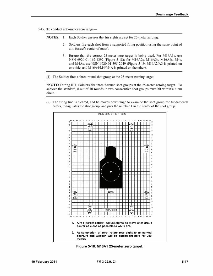
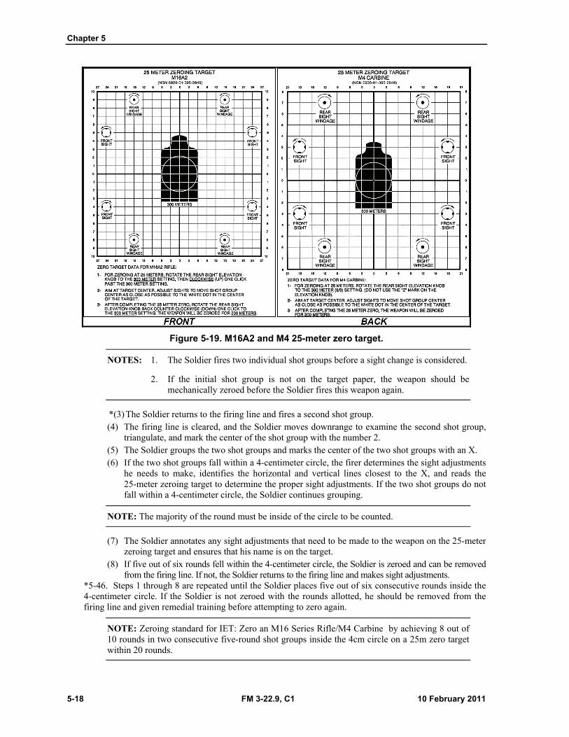
3. Ensure that the correct 25-meter zero target is being used. For M16A1s, use NSN 6920-01-167-1392 (Figure 5-18); for M16A2s, M16A3s, M16A4s, M4s, and M4As, use NSN 6920-01-395-2949 (Figure 5-19; M16A2/A3 is printed on one side, and M16A4/M4/M4A is printed on the other).
(1) The Soldier fires a three-round shot group at the 25-meter zeroing target.
*NOTE: During IET, Soldiers fire three 5-round shot groups at the 25-meter zeroing target. To achieve the standard, 8 out of 10 rounds in two consecutive shot groups must hit within a 4-cm circle.
(2) The firing line is cleared, and he moves downrange to examine the shot group for fundamental errors, triangulates the shot group, and puts the number 1 in the center of the shot group.
Figure 5-18. M16A1 25-meter zero target.
Chapter 5
5-18 FM 3-22.9, C1 10 February 2011
Figure 5-19. M16A2 and M4 25-meter zero target.
NOTES: 1. The Soldier fires two individual shot groups before a sight change is considered.
2. If the initial shot group is not on the target paper, the weapon should be mechanically zeroed before the Soldier fires this weapon again.
*(3) The Soldier returns to the firing line and fires a second shot group. (4) The firing line is cleared, and the Soldier moves downrange to examine the second shot group,
triangulate, and mark the center of the shot group with the number 2. (5) The Soldier groups the two shot groups and marks the center of the two shot groups with an X. (6) If the two shot groups fall within a 4-centimeter circle, the firer determines the sight adjustments
he needs to make, identifies the horizontal and vertical lines closest to the X, and reads the 25-meter zeroing target to determine the proper sight adjustments. If the two shot groups do not fall within a 4-centimeter circle, the Soldier continues grouping.
NOTE: The majority of the round must be inside of the circle to be counted.
(7) The Soldier annotates any sight adjustments that need to be made to the weapon on the 25-meter zeroing target and ensures that his name is on the target.
(8) If five out of six rounds fell within the 4-centimeter circle, the Soldier is zeroed and can be removed from the firing line. If not, the Soldier returns to the firing line and makes sight adjustments.
*5-46. Steps 1 through 8 are repeated until the Soldier places five out of six consecutive rounds inside the 4-centimeter circle. If the Soldier is not zeroed with the rounds allotted, he should be removed from the firing line and given remedial training before attempting to zero again.
NOTE: Zeroing standard for IET: Zero an M16 Series Rifle/M4 Carbine by achieving 8 out of 10 rounds in two consecutive five-round shot groups inside the 4cm circle on a 25m zero target within 20 rounds.
Downrange Feedback
10 February 2011 FM 3-22.9, C1 5-19
*5-47. Once firing proficiency has been demonstrated from the supported firing position, zeroing exercises can be conducted from the unsupported firing position.
CONDUCT OF A 25-METER ZERO FIRING USING THE LOCATION OF MISSES AND HITS
SYSTEM
*5-48. When using the LOMAH system on a KD range, zero confirmation is part of the program and will be shot as the first scenario. To achieve a 300-meter zero using the LOMAH system, the Soldier shoots six rounds at the 175-meter/200-yard target while aiming at the target's center of mass. The outcome is evaluated using the following guidelines:
If the shot group falls within the 11-inch circle on the LOMAH monitor, the Soldier continues the programmed scenario, which is identical to the downrange feedback scenario without LOMAH.
If the Soldier shoots a shot group that is 11 inches or smaller but is clearly not zeroed, the instructor/trainer assists the Soldier in making sight adjustments based upon the data provided on the LOMAH monitor.
If the shot group is not tight (greater than 11 inches), the Soldier should be removed from the firing line and given remedial training on the four fundamentals of marksmanship.
* CONDUCT OF A 200-METER ZERO FIRING
*5-49. For a unit deployed to an urban area, many engagements happen at 200 meters or closer. Out to 200 meters, a 200-meter zero keeps the point of impact closer to the point of aim than a 300-meter zero.
*5-50. The 200-meter zero is not an alternate to the 300-meter zero; rather, it is a supplemental zero. The standard 300-meter zero will continue to be used when units are conducting standard rifle qualification or when units are deploying to an area where most engagements occur at distances greater than 200 meters.
*NOTE: 200-meter zero procedures mirror those of standard zero procedures, with the exception of the target offsets. See Appendix F for more information about preparing 200-meter zero target offsets for various sights.
SECTION III. KNOWN DISTANCE RANGE This section provides guidelines for the instructor/trainer to conduct a KD range and apply the effects of wind and gravity. This section also addresses three types of KD ranges: the standard KD range, the KD record fire range, and the modified field fire range.
NOTE: See Table 5-4 for the current training program.
CONCEPT 5-51. A KD range has three primary objectives:
(1) Fire tight shot groups at a known distance. (2) *Make sight adjustments at range while experiencing the effects of wind and gravity. (3) Participate in marksmanship testing.
5-52. KD firing brings the Soldier one step closer to being able to fire during combat. The Soldier is provided information concerning the precise hit-or-miss location of every bullet fired. KD firing is conducted with a single, clearly visible target at a known distance, and the Soldier can establish a position that provides a natural point of aim on that single target. Consider the following:
On the standard KD range, Soldiers fire at 100-, 200-, and 300-meter targets without any time constraints.
Chapter 5
5-20 FM 3-22.9, C1 10 February 2011
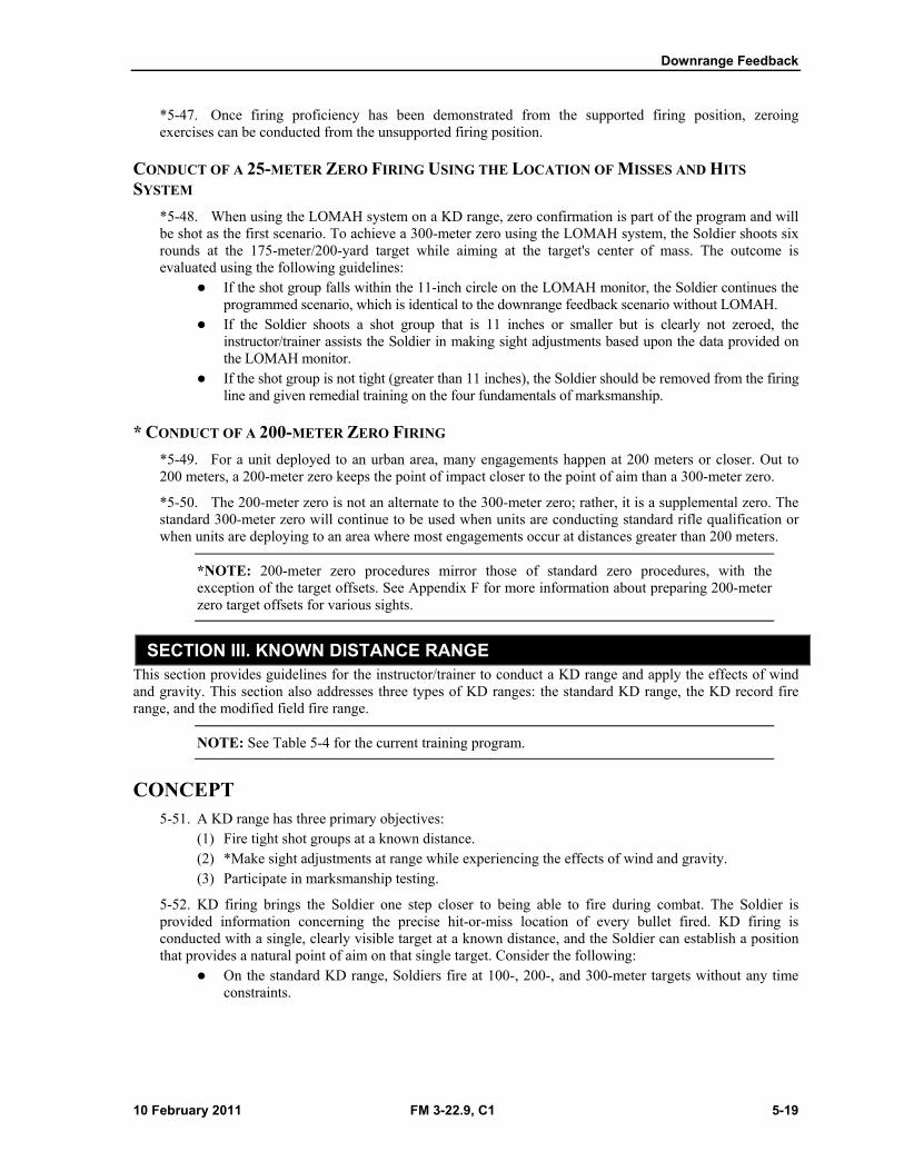
Table 5-4. Downrange feedback.
DOWNRANGE FEEDBACK
Instructional Intent
• Reinforce PMI while shooting from the prone supported and unsupported firing positions.
• Build the Soldier’s confidence in his ability to hit where he aims while applying the effects of wind and gravity at range.
Special Instructions
Ensure that— • The effects of wind and gravity are thoroughly explained.
• The rear sight is on the proper setting (M16A2/3=8/3; M16A4 and M4=6/3 flush; M16A1=the unmarked aperture, short-range).
• The rear sight aperture is set on 300, not 800.
Observables
• Spotters provide correct feedback to firers.
• Soldiers hit 8 of 10 targets at 100 meters.
• Soldiers hit 14 of 20 targets at 200 meters.
• Soldiers hit 5 of 10 targets at 300 meters.
On the KD record fire range, Soldiers fire at 100-, 200-, and 300-meter targets with time constraints.
On the modified field fire range, Soldiers fire at 100-, 200-, and 300-meter targets on a standard 50- to 300-meter field fire qualification range.
NOTES: 1. If a qualification range is not available, this exercise may be shot on a standard 75- to 300-meter field fire range. Targets and target frames must be set up to accommodate this training.
2. On ranges that are built in yards instead of meters, the same KD targets will be used. The difference is so small that it does not need to be considered.
The KD range does not require Soldiers to detect targets, estimate ranges to targets, scan sectors of fire, respond to surprise targets, respond to short-exposure targets, or engage multiple targets.
An advantage of a KD range is the ability to see precisely where each bullet hits. To benefit from this training, Soldiers must clearly see the results of each firing, whether a group, single shot, or 10-round exercise.
KNOWN DISTANCE TARGET DESCRIPTION 5-53. Downrange feedback training should include detailed explanations of the targets. Consider the following:
KD targets are large enough to capture all bullets fired. Standard E-type and F-type silhouettes can be used if standard KD targets are not available.
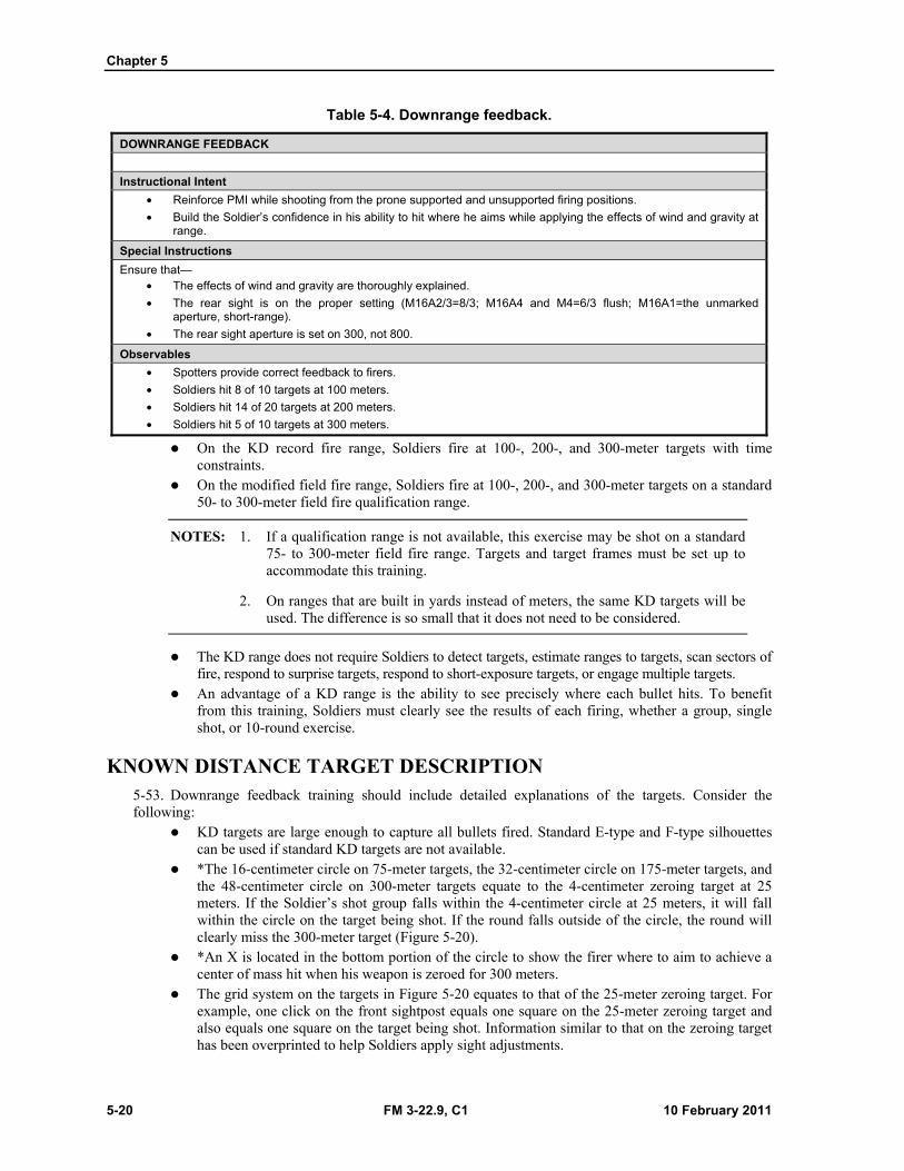
*The 16-centimeter circle on 75-meter targets, the 32-centimeter circle on 175-meter targets, and the 48-centimeter circle on 300-meter targets equate to the 4-centimeter zeroing target at 25 meters. If the Soldier’s shot group falls within the 4-centimeter circle at 25 meters, it will fall within the circle on the target being shot. If the round falls outside of the circle, the round will clearly miss the 300-meter target (Figure 5-20).
*An X is located in the bottom portion of the circle to show the firer where to aim to achieve a center of mass hit when his weapon is zeroed for 300 meters.
The grid system on the targets in Figure 5-20 equates to that of the 25-meter zeroing target. For example, one click on the front sightpost equals one square on the 25-meter zeroing target and also equals one square on the target being shot. Information similar to that on the zeroing target has been overprinted to help Soldiers apply sight adjustments.
Downrange Feedback
10 February 2011 FM 3-22.9, C1 5-21
*Figure 5-20. Downrange feedback targets.
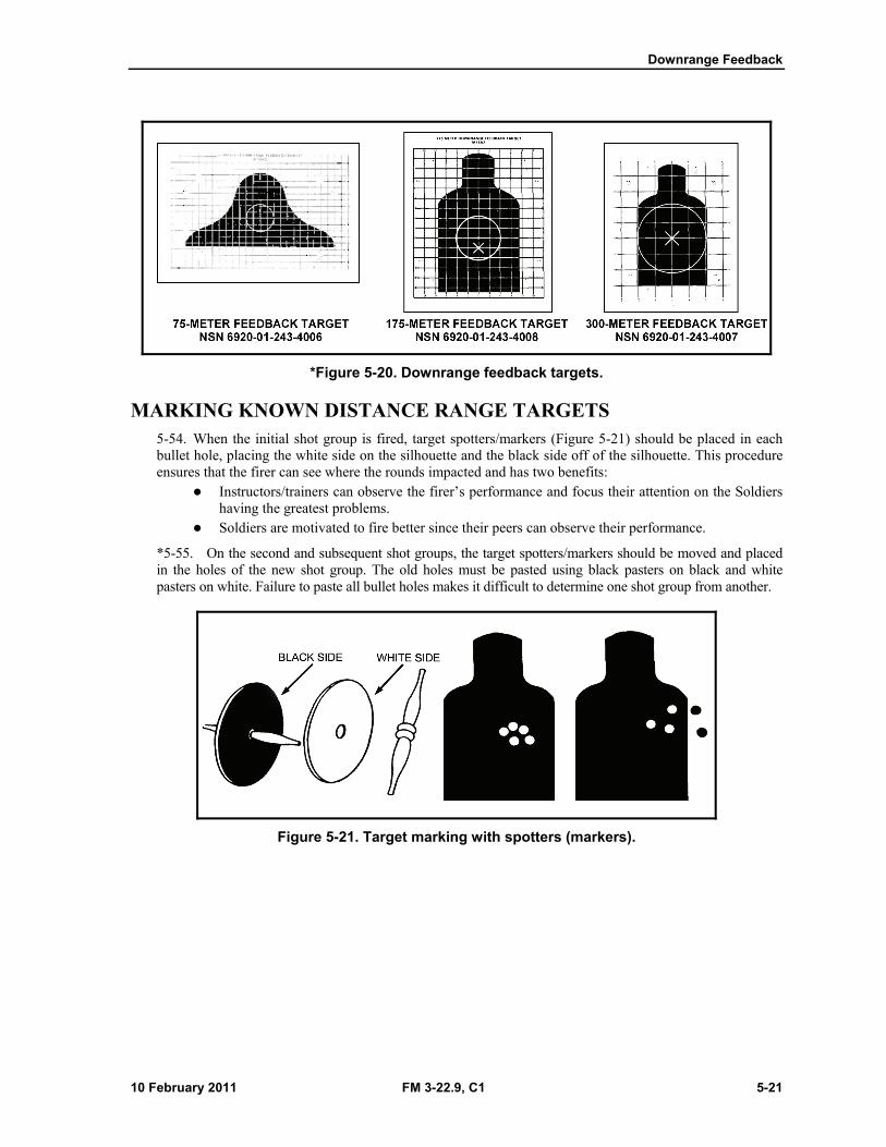
MARKING KNOWN DISTANCE RANGE TARGETS 5-54. When the initial shot group is fired, target spotters/markers (Figure 5-21) should be placed in each bullet hole, placing the white side on the silhouette and the black side off of the silhouette. This procedure ensures that the firer can see where the rounds impacted and has two benefits:
Instructors/trainers can observe the firer’s performance and focus their attention on the Soldiers having the greatest problems.
Soldiers are motivated to fire better since their peers can observe their performance.
*5-55. On the second and subsequent shot groups, the target spotters/markers should be moved and placed in the holes of the new shot group. The old holes must be pasted using black pasters on black and white pasters on white. Failure to paste all bullet holes makes it difficult to determine one shot group from another.
Figure 5-21. Target marking with spotters (markers).
Chapter 5
5-22 FM 3-22.9, C1 10 February 2011
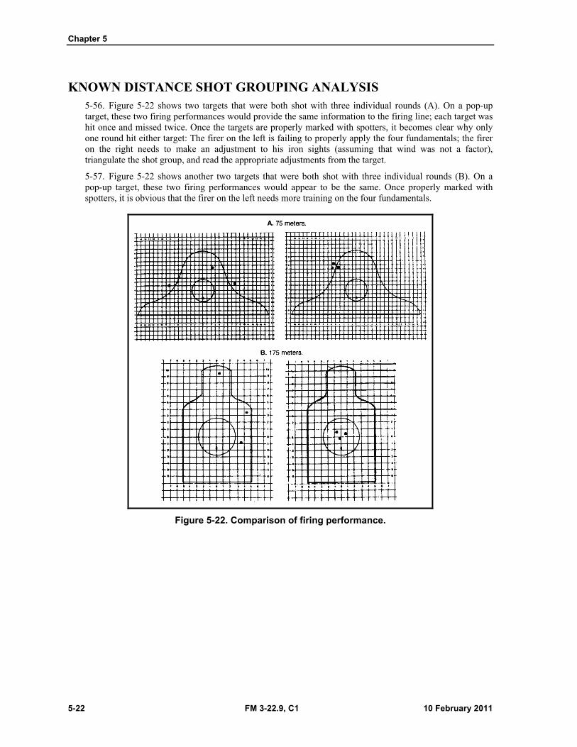
KNOWN DISTANCE SHOT GROUPING ANALYSIS 5-56. Figure 5-22 shows two targets that were both shot with three individual rounds (A). On a pop-up target, these two firing performances would provide the same information to the firing line; each target was hit once and missed twice. Once the targets are properly marked with spotters, it becomes clear why only one round hit either target: The firer on the left is failing to properly apply the four fundamentals; the firer on the right needs to make an adjustment to his iron sights (assuming that wind was not a factor), triangulate the shot group, and read the appropriate adjustments from the target.
5-57. Figure 5-22 shows another two targets that were both shot with three individual rounds (B). On a pop-up target, these two firing performances would appear to be the same. Once properly marked with spotters, it is obvious that the firer on the left needs more training on the four fundamentals.
Figure 5-22. Comparison of firing performance.
Downrange Feedback
10 February 2011 FM 3-22.9, C1 5-23
KNOWN DISTANCE ZEROING 5-58. The 300-meter target can be used to confirm weapon zero or to refine the zero obtained on the 25-meter range. When Soldiers properly compensate for the wind, the zero on this target is more valid than the zero obtained on the 25-meter range. Soldiers should fire two five-round shot groups to confirm zero or three-round shot groups to refine their zero. The pit crews should spot targets after each shot group is fired. If the crosswind exceeds five miles per hour, KD zeroing should not be attempted.
*NOTES: 1. For M16A2/3/4, M4, and M4A1 weapons only: Soldiers should use the unmarked aperture for zeroing and target engagement at all distances on the KD range. When engaging targets beyond 300 meters, the elevation wheel should be adjusted to the range of the target. When zeroed at 300 meters, the numbers on the elevation wheel correspond to the range of the target (expressed in meters). For example, the firer would click the elevation wheel to 4 to engage a 400-meter target.
2. For M16A1 rifles only: Soldiers should use the unmarked aperture (short-range) for refining zero at 300 meters. For target engagements beyond the 300-meter line, Soldiers should use the long-range aperture (L).
*MINUTE OF ANGLE
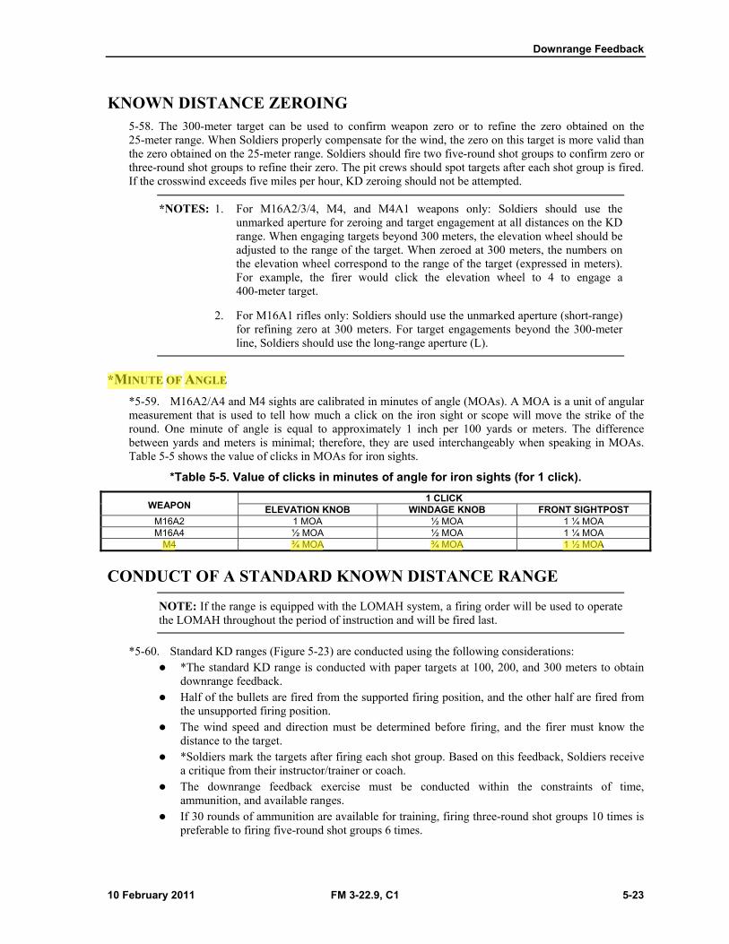
*5-59. M16A2/A4 and M4 sights are calibrated in minutes of angle (MOAs). A MOA is a unit of angular measurement that is used to tell how much a click on the iron sight or scope will move the strike of the round. One minute of angle is equal to approximately 1 inch per 100 yards or meters. The difference between yards and meters is minimal; therefore, they are used interchangeably when speaking in MOAs. Table 5-5 shows the value of clicks in MOAs for iron sights.
*Table 5-5. Value of clicks in minutes of angle for iron sights (for 1 click).
WEAPON 1 CLICK
ELEVATION KNOB WINDAGE KNOB FRONT SIGHTPOST M16A2 1 MOA ½ MOA 1 ¼ MOA M16A4 ½ MOA ½ MOA 1 ¼ MOA
M4 ¾ MOA ¾ MOA 1 ½ MOA
CONDUCT OF A STANDARD KNOWN DISTANCE RANGE
NOTE: If the range is equipped with the LOMAH system, a firing order will be used to operate the LOMAH throughout the period of instruction and will be fired last.
*5-60. Standard KD ranges (Figure 5-23) are conducted using the following considerations: *The standard KD range is conducted with paper targets at 100, 200, and 300 meters to obtain
downrange feedback. Half of the bullets are fired from the supported firing position, and the other half are fired from
the unsupported firing position. The wind speed and direction must be determined before firing, and the firer must know the
distance to the target. *Soldiers mark the targets after firing each shot group. Based on this feedback, Soldiers receive
a critique from their instructor/trainer or coach. The downrange feedback exercise must be conducted within the constraints of time,
ammunition, and available ranges. If 30 rounds of ammunition are available for training, firing three-round shot groups 10 times is
preferable to firing five-round shot groups 6 times.
Chapter 5
5-24 FM 3-22.9, C1 10 February 2011
Once the Soldier understands the concept for adjusting the point of aim to compensate for the effects of wind and gravity, he is ready to apply his knowledge on the field fire range.
*100-METER TARGETS
5-61. Instructors/trainers can provide feedback after each round, each three-round shot group, or each five-round shot group on the 100-meter feedback targets. No time limit is placed on the firer. Soldiers fire from the supported firing position and from the unsupported firing position. Then, the targets are marked and evaluated. Feedback consists of a critique of performance, adjustments to the point of aim, effects of wind and gravity, and shot placement. Target spotters mark the bullet holes so hits can be viewed from the firing line.
NOTE: IET Soldiers fire one five-round shot group from the supported firing position and one five-round shot group from the unsupported firing position. They must hit 8 out of 10 targets.
*200-METER TARGETS
5-62. Firers engage the 200-meter target using the same downrange procedures as when engaging the 100-meter target.
NOTE: IET Soldiers fire 10 rounds from the supported firing position and 10 rounds from the unsupported firing position. They must hit 14 out of 20 targets.
300-METER TARGETS
5-63. Firers engage the 300-meter target using the same downrange procedures as when engaging the 100-meter target.
NOTE: IET Soldiers fire one five-round shot group from the supported firing position and one five-round shot group from the unsupported firing position. They must hit 5 out of 10 targets.
KNOWN DISTANCE RECORD FIRE RANGE
NOTE: See paragraphs 6-79 through 6-82 of Chapter 6 for information about the alternate course KD record fire range.
MODIFIED FIELD FIRE RANGE 5-64. A modified field fire range can be used for downrange feedback. To conduct downrange feedback, minor changes must be made to a standard field fire range. Target frames, like those used on the 25-meter range, are placed on a standard qualification range at 100, 200, and 300 meters. The standard KD range or the KD record fire range can be conducted on the modified field fire range.
NOTE: The firing line must be cleared, moved to the targets for marking, and returned each time a firing order fires.
Chapter 5
5-26 FM 3-22.9, C1 10 February 2011
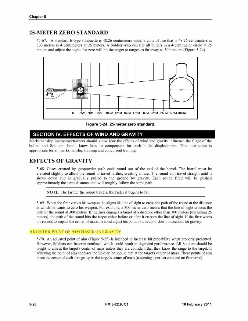
25-METER ZERO STANDARD *5-67. A standard E-type silhouette is 48.26 centimeters wide; a cone of fire that is 48.26 centimeters at 300 meters is 4 centimeters at 25 meters. A Soldier who can fire all bullets in a 4-centimeter circle at 25 meters and adjust the sights for zero will hit the target at ranges as far away as 300 meters (Figure 5-24).
Figure 5-24. 25-meter zero standard.
SECTION IV. EFFECTS OF WIND AND GRAVITY Marksmanship instructors/trainers should know how the effects of wind and gravity influence the flight of the bullet, and Soldiers should know how to compensate for such bullet displacement. This instruction is appropriate for all marksmanship training and concurrent training.
EFFECTS OF GRAVITY 5-68. Gases created by gunpowder push each round out of the end of the barrel. The barrel must be elevated slightly to allow the round to travel farther, creating an arc. The round will travel straight until it slows down and is gradually pulled to the ground by gravity. Each round fired will be pushed approximately the same distance and will roughly follow the same path.
NOTE: The farther the round travels, the faster it begins to fall.
5-69. When the firer zeroes his weapon, he aligns his line of sight to cross the path of the round at the distance at which he wants to zero his weapon. For example, a 300-meter zero means that the line of sight crosses the path of the round at 300 meters. If the firer engages a target at a distance other than 300 meters (excluding 25 meters), the path of the round hits the target either before or after it crosses the line of sight. If the firer wants his rounds to impact the center of mass, he must adjust his point of aim up or down to account for gravity.
ADJUSTED POINT OF AIM BASED ON GRAVITY
5-70. An adjusted point of aim (Figure 5-25) is intended to increase hit probability when properly presented. However, Soldiers can become confused, which could result in degraded performance. All Soldiers should be taught to aim at the target's center of mass unless they are confident that they know the range to the target. If adjusting the point of aim confuses the Soldier, he should aim at the target's center of mass. These points of aim place the center of each shot group in the target's center of mass (assuming a perfect zero and no firer error).
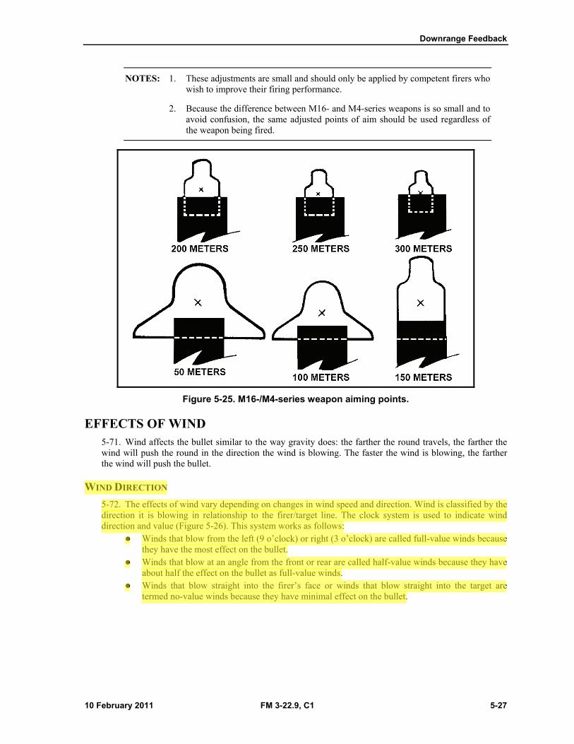
Downrange Feedback
10 February 2011 FM 3-22.9, C1 5-27
NOTES: 1. These adjustments are small and should only be applied by competent firers who wish to improve their firing performance.
2. Because the difference between M16- and M4-series weapons is so small and to avoid confusion, the same adjusted points of aim should be used regardless of the weapon being fired.
Figure 5-25. M16-/M4-series weapon aiming points.
EFFECTS OF WIND 5-71. Wind affects the bullet similar to the way gravity does: the farther the round travels, the farther the wind will push the round in the direction the wind is blowing. The faster the wind is blowing, the farther the wind will push the bullet.
WIND DIRECTION
5-72. The effects of wind vary depending on changes in wind speed and direction. Wind is classified by the direction it is blowing in relationship to the firer/target line. The clock system is used to indicate wind direction and value (Figure 5-26). This system works as follows:
Winds that blow from the left (9 o’clock) or right (3 o’clock) are called full-value winds because they have the most effect on the bullet.
Winds that blow at an angle from the front or rear are called half-value winds because they have about half the effect on the bullet as full-value winds.
Winds that blow straight into the firer’s face or winds that blow straight into the target are termed no-value winds because they have minimal effect on the bullet.
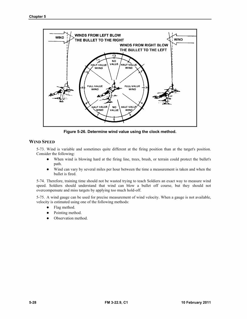
Chapter 5
5-28 FM 3-22.9, C1 10 February 2011
Figure 5-26. Determine wind value using the clock method.
WIND SPEED
5-73. Wind is variable and sometimes quite different at the firing position than at the target's position. Consider the following:
When wind is blowing hard at the firing line, trees, brush, or terrain could protect the bullet's path.
Wind can vary by several miles per hour between the time a measurement is taken and when the bullet is fired.
5-74. Therefore, training time should not be wasted trying to teach Soldiers an exact way to measure wind speed. Soldiers should understand that wind can blow a bullet off course, but they should not overcompensate and miss targets by applying too much hold-off.
5-75. A wind gauge can be used for precise measurement of wind velocity. When a gauge is not available, velocity is estimated using one of the following methods:
Flag method. Pointing method. Observation method.

Chapter 5
5-30 FM 3-22.9, C1 10 February 2011
Pointing Method
5-77. If a flag is not visible, the firer can use the pointing method. To perform the pointing method (Figure 5-28)—
(1) Drop a piece of paper, leaf, or other light material from the shoulder. (2) Point directly at the place where it lands. (3) Estimate the angle created by the pointing arm. (4) Divide this angle by the number 4.
NOTE: The answer is the approximate wind speed at the firing position expressed in miles per hour.
Figure 5-28. Determine wind speed using the pointing method.
Observation Method
5-78. If the flag or pointing methods cannot be used, the following information can assist in determining wind velocities:
Winds less than 3 miles per hour can barely be felt by the firer, but the presence of slight wind can be determined by drifting smoke.
Winds of 3 to 5 miles per hour can be felt lightly over the firer’s face. Winds of 5 to 8 miles per hour constantly move the leaves of trees. Winds of 8 to 12 miles per hour raise dust and loose paper. Winds of 12 to 15 miles per hour cause small trees to sway.
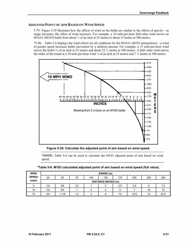
Downrange Feedback
10 February 2011 FM 3-22.9, C1 5-31
ADJUSTED POINT OF AIM BASED ON WIND SPEED
5-79. Figure 5-29 illustrates how the effects of wind on the bullet are similar to the effects of gravity—as range increases, the effect of wind increases. For example, a 10 mile-per-hour full-value wind moves an M16A1 (M193) bullet from about ½ of an inch at 25 meters to about 15 inches at 300 meters.
*5-80. Table 5-6 displays the wind effects for all conditions for the M16A1 (M193 ammunition)—a wind of greater speed increases bullet movement by a uniform amount. For example, a 15 mile-per-hour wind moves the bullet ¾ of an inch at 25 meters and about 22 ½ inches at 300 meters. A half-value wind moves the strike of the round in a 10 mile-per-hour wind ¼ of an inch at 25 meters and 7 ½ inches at 300 meters.
Figure 5-29. Calculate the adjusted point of aim based on wind speed.
*NOTE: Table 5-6 can be used to calculate the M193 adjusted point of aim based on wind speed.
*Table 5-6. M193 calculated adjusted point of aim based on wind speed (full value).
WIND
SPEED
(mph)
RANGE (m)
25 50 75 100 150 175 200 250 300
DISTANCE MOVED (in)
5 1/4 3/8 1/2 1 2 2.5 3.5 5 7.5
10 1/2 3/4 1 2 4 5 7 10 15
15 3/4 1-1/8 1.5 3 6 7.5 10.5 15 22.5
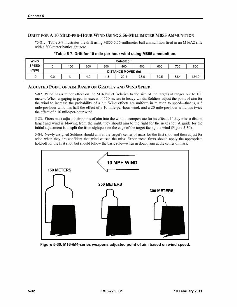
Chapter 5
5-32 FM 3-22.9, C1 10 February 2011
DRIFT FOR A 10 MILE-PER-HOUR WIND USING 5.56-MILLIMETER M855 AMMUNITION
*5-81. Table 5-7 illustrates the drift using M855 5.56-millimeter ball ammunition fired in an M16A2 rifle with a 300-meter battlesight zero.
*Table 5-7. Drift for 10 mile-per-hour wind using M855 ammunition.
WIND
SPEED
(mph)
RANGE (m)
0 100 200 300 400 500 600 700 800
DISTANCE MOVED (in)
10 0.0 1.1 4.9 11.8 22.4 38.0 59.5 88.4 124.9
ADJUSTED POINT OF AIM BASED ON GRAVITY AND WIND SPEED
5-82. Wind has a minor effect on the M16 bullet (relative to the size of the target) at ranges out to 100 meters. When engaging targets in excess of 150 meters in heavy winds, Soldiers adjust the point of aim for the wind to increase the probability of a hit. Wind effects are uniform in relation to speed—that is, a 5 mile-per-hour wind has half the effect of a 10 mile-per-hour wind, and a 20 mile-per-hour wind has twice the effect of a 10 mile-per-hour wind.
5-83. Firers must adjust their points of aim into the wind to compensate for its effects. If they miss a distant target and wind is blowing from the right, they should aim to the right for the next shot. A guide for the initial adjustment is to split the front sightpost on the edge of the target facing the wind (Figure 5-30).
5-84. Newly assigned Soldiers should aim at the target's center of mass for the first shot, and then adjust for wind when they are confident that wind caused the miss. Experienced firers should apply the appropriate hold-off for the first shot, but should follow the basic rule—when in doubt, aim at the center of mass.
Figure 5-30. M16-/M4-series weapons adjusted point of aim based on wind speed.
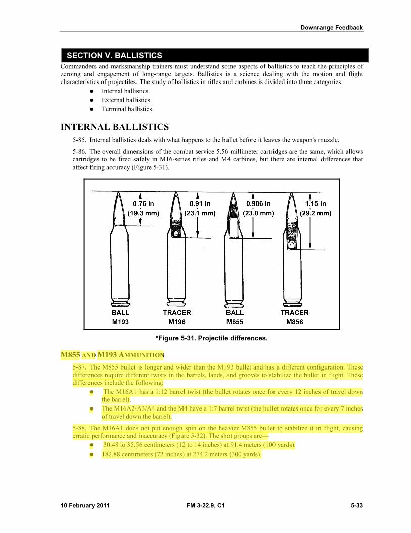
Downrange Feedback
10 February 2011 FM 3-22.9, C1 5-33
SECTION V. BALLISTICS Commanders and marksmanship trainers must understand some aspects of ballistics to teach the principles of zeroing and engagement of long-range targets. Ballistics is a science dealing with the motion and flight characteristics of projectiles. The study of ballistics in rifles and carbines is divided into three categories:
Internal ballistics. External ballistics. Terminal ballistics.
INTERNAL BALLISTICS 5-85. Internal ballistics deals with what happens to the bullet before it leaves the weapon's muzzle.
5-86. The overall dimensions of the combat service 5.56-millimeter cartridges are the same, which allows cartridges to be fired safely in M16-series rifles and M4 carbines, but there are internal differences that affect firing accuracy (Figure 5-31).
*Figure 5-31. Projectile differences.
M855 AND M193 AMMUNITION
5-87. The M855 bullet is longer and wider than the M193 bullet and has a different configuration. These differences require different twists in the barrels, lands, and grooves to stabilize the bullet in flight. These differences include the following:
The M16A1 has a 1:12 barrel twist (the bullet rotates once for every 12 inches of travel down the barrel).
The M16A2/A3/A4 and the M4 have a 1:7 barrel twist (the bullet rotates once for every 7 inches of travel down the barrel).
5-88. The M16A1 does not put enough spin on the heavier M855 bullet to stabilize it in flight, causing erratic performance and inaccuracy (Figure 5-32). The shot groups are—
30.48 to 35.56 centimeters (12 to 14 inches) at 91.4 meters (100 yards). 182.88 centimeters (72 inches) at 274.2 meters (300 yards).
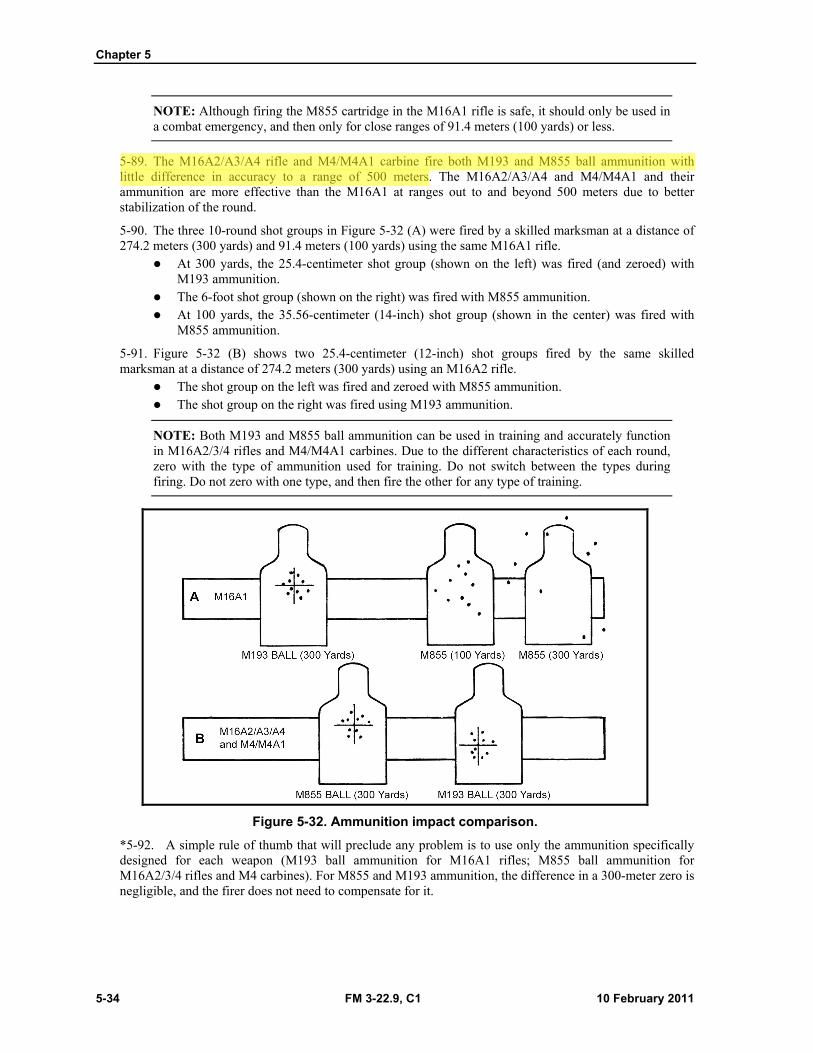
Chapter 5
5-34 FM 3-22.9, C1 10 February 2011
NOTE: Although firing the M855 cartridge in the M16A1 rifle is safe, it should only be used in a combat emergency, and then only for close ranges of 91.4 meters (100 yards) or less.
5-89. The M16A2/A3/A4 rifle and M4/M4A1 carbine fire both M193 and M855 ball ammunition with little difference in accuracy to a range of 500 meters. The M16A2/A3/A4 and M4/M4A1 and their ammunition are more effective than the M16A1 at ranges out to and beyond 500 meters due to better stabilization of the round.
5-90. The three 10-round shot groups in Figure 5-32 (A) were fired by a skilled marksman at a distance of 274.2 meters (300 yards) and 91.4 meters (100 yards) using the same M16A1 rifle.
At 300 yards, the 25.4-centimeter shot group (shown on the left) was fired (and zeroed) with M193 ammunition.
The 6-foot shot group (shown on the right) was fired with M855 ammunition. At 100 yards, the 35.56-centimeter (14-inch) shot group (shown in the center) was fired with
M855 ammunition.
5-91. Figure 5-32 (B) shows two 25.4-centimeter (12-inch) shot groups fired by the same skilled marksman at a distance of 274.2 meters (300 yards) using an M16A2 rifle.
The shot group on the left was fired and zeroed with M855 ammunition. The shot group on the right was fired using M193 ammunition.
NOTE: Both M193 and M855 ball ammunition can be used in training and accurately function in M16A2/3/4 rifles and M4/M4A1 carbines. Due to the different characteristics of each round, zero with the type of ammunition used for training. Do not switch between the types during firing. Do not zero with one type, and then fire the other for any type of training.
Figure 5-32. Ammunition impact comparison.
*5-92. A simple rule of thumb that will preclude any problem is to use only the ammunition specifically designed for each weapon (M193 ball ammunition for M16A1 rifles; M855 ball ammunition for M16A2/3/4 rifles and M4 carbines). For M855 and M193 ammunition, the difference in a 300-meter zero is negligible, and the firer does not need to compensate for it.
Downrange Feedback
10 February 2011 FM 3-22.9, C1 5-35
EXTERNAL BALLISTICS 5-93. External ballistics deals with factors affecting the flight path of the bullet between the weapon's muzzle and the target.
5-94. Soldiers must understand the basics of external ballistics so they can make necessary scope adjustments or hold compensations to allow them to hit the target. The external ballistic factors that affect bullet trajectory are:
Gravity. Muzzle velocity. Air resistance (drag). Altitude or air density. Temperature. Trajectory. Wind. Angles.
GRAVITY
*5-95. The force of gravity on a bullet is constant regardless of its weight, shape, or velocity.
*NOTE: See paragraphs 5-68 through 5-70 for more information about the effects of gravity.
MUZZLE VELOCITY
*5-96. Muzzle velocity is the speed of a bullet as it leaves the barrel, measured in feet per second. The bullet begins to slow down as soon as it exits the barrel.
AIR RESISTANCE (DRAG)
5-97. Air resistance, or drag, immediately produces a slowing effect on a bullet.
ALTITUDE OR AIR DENSITY
5-98. The greater the altitude, the thinner the air and the longer the bullet will travel (with a correspondingly flatter trajectory). Each 5,000-foot elevation will raise the strike of the bullet ½ to 1 minute of angle (MOA).
TEMPERATURE
5-99. Deviation from standard daytime temperature (59 degrees Fahrenheit/15 degrees Celsius) affects bullet trajectory.
Cold Temperatures
5-100. Cold air is denser than warm air; the bullet must travel through more tightly packed air particles. This causes the bullet to lose velocity, causing the bullet to impact lower than intended. Cooler air also causes lower chamber pressure, which reduces the initial velocity.
Hot Temperatures
5-101. Warm or hot temperatures cause the strike of the round to move up.
Chapter 5
5-36 FM 3-22.9, C1 10 February 2011
TRAJECTORY
*5-102. When a projectile exits the barrel, gravity immediately takes effect, causing the bullet to drop from the line of departure, otherwise known as the line of bore. As the projectile travels downrange, air drag decreases the velocity. These effects create the projectile’s trajectory.
Line of Sight
5-103. The line of sight is an imaginary straight line extending from the firer’s eye through the telescopic sight, or rear and front sight, to the target.
Line of Departure
5-104. The line of departure is an imaginary straight line extending from the center of the barrel to infinity.
Zero Range
5-105. Zero range is where the projectile intersects the line of sight. It occurs twice—once on the way up and once on the way down.
Apex
5-106. Otherwise known as midrange trajectory, the apex is the point where the projectile is at its highest in relation to the line of sight.
Bullet Path
5-107. The bullet path is the relationship of a projectile and the line of sight at any given range (normally expressed in inches).
WIND
5-108. External factors influence the trajectory relative to the point of aim, such as wind, altitude, temperature, humidity, and barometric pressure. Wind is by far the most significant. Consider the following effects of wind:
Because the bullet is moving through the air, the air moves the bullet. Wind deflection is always in the same direction the wind is moving. A wind blowing from the left will move the bullet to the right.
Deflection decreases as the angle of the wind to the line of flight decreases.
5-109. Effectively reading and correcting for wind effects takes practice, especially at longer ranges where accuracy in correcting is more critical. To shoot accurately in the wind, a firer must know the wind velocity, the wind direction, and the value of deflection at the range at which he is shooting.
*NOTE: See paragraph 5-71 for more information on the effects of wind.
ANGLES
5-110. Firing uphill or downhill normally causes the bullet to hit high relative to a horizontal trajectory. If the firer is firing on an angle up or down at a slanted range of 100 meters, the point of impact will be higher than it would be for a level shot of 100 meters. The height depends on the angle.
5-111. Gravity acts on a bullet only during the horizontal component of its flight (the distance from the firer to the target measured as if they were both at the same level). Since the horizontal component will always be less than the slanted range, gravity will not pull the bullet down as far as it would if the range were level.
Downrange Feedback
10 February 2011 FM 3-22.9, C1 5-37
5-112. Firing uphill or downhill causes the wind to affect the shot over the entire slant range. The firer should aim at the target as if it were 25 meters away and correct for wind as if it were 400 meters away. The correct method for shooting uphill or downhill is to adjust elevation based on the horizontal range and correct for wind deflection based on the slanted range.
TERMINAL BALLISTICS 5-113. Terminal ballistics deals with what happens to the bullet when it comes in contact with the target.
5-114. Bullet penetration depends on the range, velocity, bullet characteristics, and target material. Greater penetration does not always occur at close range with certain materials, since the high velocity of the 5.56-millimeter bullet causes it to disintegrate soon after impact.
BULLET DISPERSION AT RANGE 5-115. Instructors/trainers must have a working knowledge of the effects of bullet dispersion and accuracy at various ranges.
MINUTE OF ANGLE
5-116. An MOA is the standard unit of measurement used in adjusting a weapon's sights and other ballistic-related measurements. It is also used to indicate the accuracy of a weapon.
*5-117. A circle is divided into 360 degrees. Each degree is further divided into 60 minutes. Each minute is an MOA (1/60 of a degree).
5-118. An MOA is an angle beginning at the muzzle that covers 2.54 centimeters at a distance of 91.4 meters (Figure 5-33). Often, these measurements are expressed as yards; therefore, 1 MOA is 1 inch at 100 yards, 2 inches at 200 yards, and so on. To further simplify the calculation, meters can be substituted for yards.
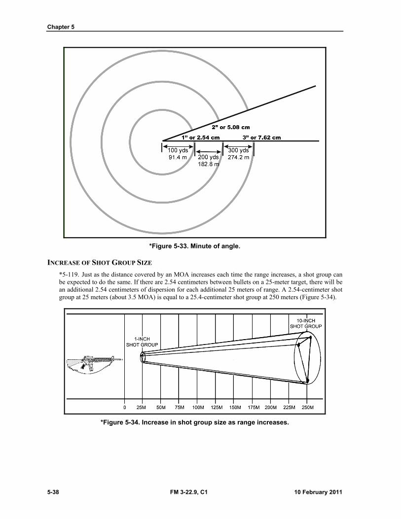
Chapter 5
5-38 FM 3-22.9, C1 10 February 2011
*Figure 5-33. Minute of angle.
INCREASE OF SHOT GROUP SIZE
*5-119. Just as the distance covered by an MOA increases each time the range increases, a shot group can be expected to do the same. If there are 2.54 centimeters between bullets on a 25-meter target, there will be an additional 2.54 centimeters of dispersion for each additional 25 meters of range. A 2.54-centimeter shot group at 25 meters (about 3.5 MOA) is equal to a 25.4-centimeter shot group at 250 meters (Figure 5-34).
*Figure 5-34. Increase in shot group size as range increases.
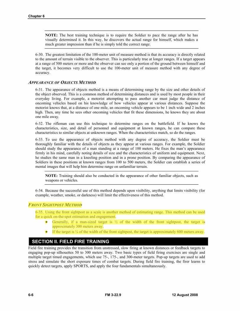
Chapter 6
6-6 FM 3-22.9 12 August 2008
NOTE: The best training technique is to require the Soldier to pace the range after he has visually determined it. In this way, he discovers the actual range for himself, which makes a much greater impression than if he is simply told the correct range.
6-30. The greatest limitation of the 100-meter unit of measure method is that its accuracy is directly related to the amount of terrain visible to the observer. This is particularly true at longer ranges. If a target appears at a range of 500 meters or more and the observer can see only a portion of the ground between himself and the target, it becomes very difficult to use the 100-meter unit of measure method with any degree of accuracy.
APPEARANCE OF OBJECTS METHOD 6-31. The appearance of objects method is a means of determining range by the size and other details of the object observed. This is a common method of determining distances and is used by most people in their everyday living. For example, a motorist attempting to pass another car must judge the distance of oncoming vehicles based on his knowledge of how vehicles appear at various distances. Suppose the motorist knows that, at a distance of one mile, an oncoming vehicle appears to be 1 inch wide and 2 inches high. Then, any time he sees other oncoming vehicles that fit these dimensions, he knows they are about one mile away.
6-32. The rifleman can use this technique to determine ranges on the battlefield. If he knows the characteristics, size, and detail of personnel and equipment at known ranges, he can compare these characteristics to similar objects at unknown ranges. When the characteristics match, so do the ranges.
6-33. To use the appearance of objects method with any degree of accuracy, the Soldier must be thoroughly familiar with the details of objects as they appear at various ranges. For example, the Soldier should study the appearance of a man standing at a range of 100 meters. He fixes the man’s appearance firmly in his mind, carefully noting details of size and the characteristics of uniform and equipment. Next, he studies the same man in a kneeling position and in a prone position. By comparing the appearance of Soldiers in these positions at known ranges from 100 to 500 meters, the Soldier can establish a series of mental images that will help him determine range on unfamiliar terrain.
NOTE: Training should also be conducted in the appearance of other familiar objects, such as weapons or vehicles.
6-34. Because the successful use of this method depends upon visibility, anything that limits visibility (for example, weather, smoke, or darkness) will limit the effectiveness of this method.
FRONT SIGHTPOST METHOD 6-35. Using the front sightpost as a scale is another method of estimating range. This method can be used for a quick on-the-spot estimation and engagement.
Generally, if a man-sized target is ½ of the width of the front sightpost, the target is approximately 300 meters away.
If the target is ¼ of the width of the front sightpost, the target is approximately 600 meters away.
SECTION II. FIELD FIRE TRAINING Field fire training provides the transition from unstressed, slow firing at known distances or feedback targets to engaging pop-up silhouettes 50 to 300 meters away. Two basic types of field firing exercises are single and multiple target timed engagements, which use 75-, 175-, and 300-meter targets. Pop-up targets are used to add stress and simulate the short exposure times of combat targets. During field fire training, the firer learns to quickly detect targets, apply SPORTS, and apply the four fundamentals simultaneously.

Chapter 6
6-12 FM 3-22.9 12 August 2008
the target is fully exposed, rather than when the tower operator activates the target switch. When practice record fire is conducted on automated record fire (ARF) ranges, these factors are included in the computer program.
NOTE: Practice Record Fire I allows peer coaching and the use of dummy ammunition. Practice Record Fire II does not allow peer coaching, and dummy ammunition will not be used.
ALIBI FIRING 6-56. Alibi firing should be conducted at the end of each firing table IAW tower operator commands. Alibis are provided during practice record fire for three reasons:
Malfunction of the weapon. Malfunction of the target mechanism. Faulty ammunition.
RANGE TRAINING AREAS 6-57. The three range training areas are as follows:
Orientation area. Ready area. Retired area.
Orientation Area 6-58. The orientation area is located so that firers cannot see the firing area. Practice record fire orientation includes instructions on the conduct of fire, safety, and range operations, including the procedures used in ready and retired areas.
Ready Area 6-59. The ready area is located near the firing range, but is positioned so that firers cannot see targets on the range. While in this area, the firer blackens the weapon sights, lubricates the weapon, and checks for defects that might cause malfunctions.
Retired Area 6-60. The retired area is about 100 meters behind the ready area. Soldiers completing practice record fire move to the retired area to clean their weapons and be critiqued on their firing performance.
PRACTICE RECORD FIRE STANDARDS 6-61. A firer who fails to qualify on his first try should refire the practice record fire range after his problem has been diagnosed and remedial training has been provided. Practice qualification ratings are shown in Table 6-8.
Table 6-8. Qualification ratings for Practice Record Fire I and II.
QUALIFICATION RATINGS
NUMBER OF TARGETS HIT
Expert 36 to 40 Sharpshooter 30 to 35
Marksman 23 to 29
Field Fire
12 August 2008 FM 3-22.9 6-15
6-69. Soldiers adhere to the following guidelines: Credit for targets hit should not be given when rounds are “saved” from difficult targets to be
used on easier targets (for example, not firing at the 300-meter target so an additional round can be fired at the 150-meter target).
When double targets are exposed, the Soldier should fire two rounds. If the first target is missed, he may fire at that same target with the second round.
Soldiers engage the target that poses the greatest threat first (normally assumed to be the closer target). No scoring distinction is made between near targets and far targets or the sequence in which they are engaged.
Credit is not given if unused ammunition from one 20-round table is added to a magazine provided for the next table.
Alibi Firing 6-70. Alibi firing is reserved for Soldiers who encounter a malfunctioning target, ammunition, or weapon. A Soldier will not be issued more than 20 rounds for Table 1, 10 rounds for Table 2, or 10 rounds for Table 3. Soldiers who fire 20 rounds, despite a target malfunction, will not be issued additional alibi rounds. There are no alibis for Soldier-induced weapon malfunctions or for targets missed during the application of immediate action procedures.
NOTE: The ammunition allocation and alibi procedures for practice record fire and record fire are conducted the same. The only exception is that coaching is authorized for practice record fire.
6-71. If a weapon or target malfunction occurs— The Soldier must apply immediate action procedures and continue to fire the exercise. After firing, the Soldier notifies the NCOIC to determine if the ammunition was faulty or if the
target malfunctioned. The NCOIC verifies the malfunction. The Soldier is permitted to fire at that target(s) with the exact number of rounds equal to the target
malfunctions. For example, a Soldier had two confirmed target malfunctions at 250 meters. Although he may have had five rounds left from the overall exercise, the Soldier receives only two rounds to engage the two 250-meter target exposures, if repaired, or the nearest target. He is not allowed to fire all five remaining rounds at the two 250-meter target exposures.
On a computerized range, the tower operator confirms that the target malfunctioned and indicates the number of malfunctions that occurred.
6-72. Inoperable weapons are uncorrectable malfunctions such as the following: A broken firing pin. Jam caused by a double feed, not by the Soldier. Failure to extract due to a broken extractor. Round in the bore.
6-73. The Soldier must apply correct immediate action procedures to eliminate stoppages. If a stoppage is determined to be correctable (for example, the Soldier did not apply correct immediate action procedures and, as a result, the Soldier did not engage the required number of targets), the Soldier is at fault.
Troubleshooting Performance 6-74. Onsite observation, detailed analysis and evaluation of individual results, and unit performance identify weaknesses such as the following:
Unserviceable weapons could cause poor zeroes or failures to fire and, therefore, failures to qualify. Some Soldiers may not qualify because of a lack of understanding of immediate action
procedures or weapon and magazine maintenance procedures.
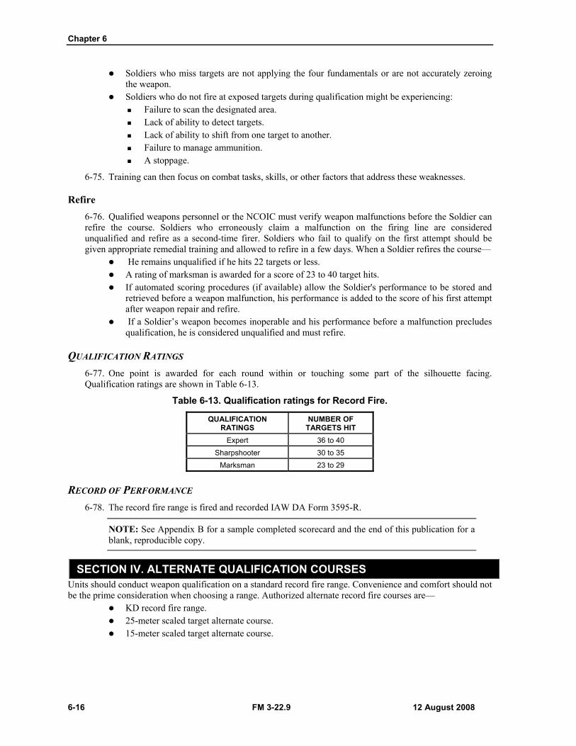
Chapter 6
6-16 FM 3-22.9 12 August 2008
Soldiers who miss targets are not applying the four fundamentals or are not accurately zeroing the weapon.
Soldiers who do not fire at exposed targets during qualification might be experiencing: Failure to scan the designated area. Lack of ability to detect targets. Lack of ability to shift from one target to another. Failure to manage ammunition. A stoppage.
6-75. Training can then focus on combat tasks, skills, or other factors that address these weaknesses.
Refire 6-76. Qualified weapons personnel or the NCOIC must verify weapon malfunctions before the Soldier can refire the course. Soldiers who erroneously claim a malfunction on the firing line are considered unqualified and refire as a second-time firer. Soldiers who fail to qualify on the first attempt should be given appropriate remedial training and allowed to refire in a few days. When a Soldier refires the course—
He remains unqualified if he hits 22 targets or less. A rating of marksman is awarded for a score of 23 to 40 target hits. If automated scoring procedures (if available) allow the Soldier's performance to be stored and
retrieved before a weapon malfunction, his performance is added to the score of his first attempt after weapon repair and refire.
If a Soldier’s weapon becomes inoperable and his performance before a malfunction precludes qualification, he is considered unqualified and must refire.
QUALIFICATION RATINGS 6-77. One point is awarded for each round within or touching some part of the silhouette facing. Qualification ratings are shown in Table 6-13.
Table 6-13. Qualification ratings for Record Fire.
QUALIFICATION RATINGS
NUMBER OF TARGETS HIT
Expert 36 to 40 Sharpshooter 30 to 35
Marksman 23 to 29
RECORD OF PERFORMANCE 6-78. The record fire range is fired and recorded IAW DA Form 3595-R.
NOTE: See Appendix B for a sample completed scorecard and the end of this publication for a blank, reproducible copy.
SECTION IV. ALTERNATE QUALIFICATION COURSES Units should conduct weapon qualification on a standard record fire range. Convenience and comfort should not be the prime consideration when choosing a range. Authorized alternate record fire courses are—
KD record fire range. 25-meter scaled target alternate course. 15-meter scaled target alternate course.
Field Fire
12 August 2008 FM 3-22.9 6-17
NOTES: 1. The official records of personnel who use an alternate qualification course are noted to distinguish alternate qualification ratings from standard record fire course ratings. For example, official personnel records are annotated as follows:
JONES, John Q. 000-00-0000 Expert 36 (record fire [RF])
JONES, John Q. 000-00-0000 Expert 38 (known distance alternate course [KDAC])
JONES, John Q. 000-00-0000 Expert 38 (alternate course [AC])
2. The uniform for all alternate qualification courses is a helmet, LBE, and IBA with all SAPI plates (if available). No other armor is required.
3. Firers should engage targets from left to right, from nearest to the farthest (50-meter, 100-meter left, 100-meter center, 100-meter right, 150-meter left, 150-meter right, 200-meter left, 200-meter right, 250-meter, and 300-meter). This ensures that firers do not forget which targets they engaged during qualification. It also alleviates the possibility of shooting each target more than the prescribed number of times.
KNOWN DISTANCE RECORD FIRE RANGE
NOTE: The KD record fire range is used by all components of the U.S. Army, U.S. Army Reserve, and Army National Guard when a record fire range is not available.
6-79. The KD record fire range allows Soldiers to engage targets at range while experiencing time constraints, feedback, and the effects of wind and gravity.
CONDUCT 6-80. To complete this course, Soldiers fire three tables. Table 6-14 depicts these three tables and provides related information, such as time constraints, number of rounds that must be fired, type of target that must be used, and the distance from the firer that the target must be placed.
NOTE: Before firing the course, all Soldiers confirm the zero of their assigned weapons by assuming the prone position and firing six rounds from the 300-meter line. Zero rounds do not count for score.
Table 6-14. Known distance record fire range firing tables and related information.
TABLE POSITION TIME CONSTRAINTS
NUMBER OF
ROUNDS
TYPE OF TARGET DISTANCE (m)
Table 1 Prone supported firing position 2 min 20 E-type silhouette target 300 Table 2 Prone unsupported firing position 60 sec 10 E-type silhouette target 200 Table 3 Prone unsupported firing position 60 sec 10 F-type silhouette target 100
QUALIFICATION RATINGS 6-81. Scoring is conducted in the pits, with the results provided after each firing table. One point is awarded for each round within or touching some part of the silhouette facing. Qualification ratings for the KD record fire range are shown in Table 6-15.
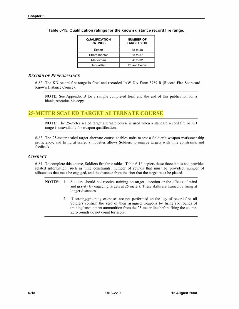
Chapter 6
6-18 FM 3-22.9 12 August 2008
Table 6-15. Qualification ratings for the known distance record fire range.
QUALIFICATION RATINGS
NUMBER OF TARGETS HIT
Expert 38 to 40 Sharpshooter 33 to 37
Marksman 26 to 32 Unqualified 25 and below
RECORD OF PERFORMANCE 6-82. The KD record fire range is fired and recorded IAW DA Form 5789-R (Record Fire Scorecard—Known Distance Course).
NOTE: See Appendix B for a sample completed form and the end of this publication for a blank, reproducible copy.
25-METER SCALED TARGET ALTERNATE COURSE
NOTE: The 25-meter scaled target alternate course is used when a standard record fire or KD range is unavailable for weapon qualification.
6-83. The 25-meter scaled target alternate course enables units to test a Soldier’s weapon marksmanship proficiency, and firing at scaled silhouettes allows Soldiers to engage targets with time constraints and feedback.
CONDUCT 6-84. To complete this course, Soldiers fire three tables. Table 6-16 depicts these three tables and provides related information, such as time constraints, number of rounds that must be provided, number of silhouettes that must be engaged, and the distance from the firer that the target must be placed.
NOTES: 1. Soldiers should not receive training on target detection or the effects of wind and gravity by engaging targets at 25 meters. These skills are trained by firing at longer distances.
2. If zeroing/grouping exercises are not performed on the day of record fire, all Soldiers confirm the zero of their assigned weapons by firing six rounds of training/sustainment ammunition from the 25-meter line before firing the course. Zero rounds do not count for score.
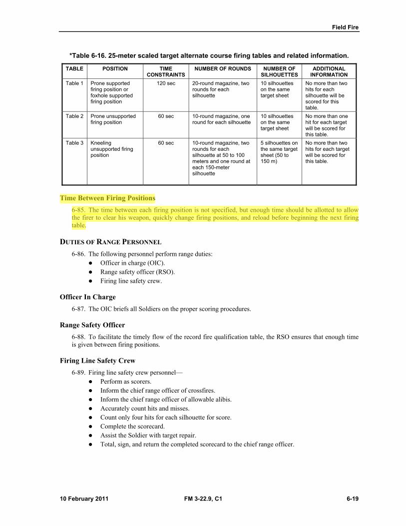
Field Fire
10 February 2011 FM 3-22.9, C1 6-19
*Table 6-16. 25-meter scaled target alternate course firing tables and related information.
TABLE POSITION TIME CONSTRAINTS
NUMBER OF ROUNDS NUMBER OF SILHOUETTES
ADDITIONAL INFORMATION
Table 1 Prone supported firing position or foxhole supported firing position
120 sec 20-round magazine, two rounds for each silhouette
10 silhouettes on the same target sheet
No more than two hits for each silhouette will be scored for this table.
Table 2 Prone unsupported firing position
60 sec 10-round magazine, one round for each silhouette
10 silhouettes on the same target sheet
No more than one hit for each target will be scored for this table.
Table 3 Kneeling unsupported firing position
60 sec 10-round magazine, two rounds for each silhouette at 50 to 100 meters and one round at each 150-meter silhouette
5 silhouettes on the same target sheet (50 to 150 m)
No more than two hits for each target will be scored for this table.
Time Between Firing Positions
6-85. The time between each firing position is not specified, but enough time should be allotted to allow the firer to clear his weapon, quickly change firing positions, and reload before beginning the next firing table.
DUTIES OF RANGE PERSONNEL
6-86. The following personnel perform range duties: Officer in charge (OIC). Range safety officer (RSO). Firing line safety crew.
Officer In Charge
6-87. The OIC briefs all Soldiers on the proper scoring procedures.
Range Safety Officer
6-88. To facilitate the timely flow of the record fire qualification table, the RSO ensures that enough time is given between firing positions.
Firing Line Safety Crew
6-89. Firing line safety crew personnel— Perform as scorers. Inform the chief range officer of crossfires. Inform the chief range officer of allowable alibis. Accurately count hits and misses. Count only four hits for each silhouette for score. Complete the scorecard. Assist the Soldier with target repair. Total, sign, and return the completed scorecard to the chief range officer.
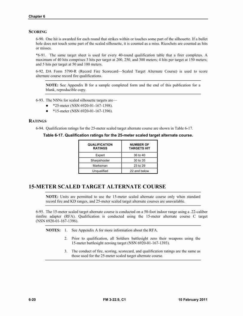
Chapter 6
6-20 FM 3-22.9, C1 10 February 2011
SCORING
6-90. One hit is awarded for each round that strikes within or touches some part of the silhouette. If a bullet hole does not touch some part of the scaled silhouette, it is counted as a miss. Ricochets are counted as hits or misses.
*6-91. The same target sheet is used for every 40-round qualification table that a firer completes. A maximum of 40 hits comprises 3 hits per target at 200, 250, and 300 meters; 4 hits per target at 150 meters; and 5 hits per target at 50 and 100 meters.
6-92. DA Form 5790-R (Record Fire Scorecard—Scaled Target Alternate Course) is used to score alternate course record fire qualifications.
NOTE: See Appendix B for a sample completed form and the end of this publication for a blank, reproducible copy.
6-93. The NSNs for scaled silhouette targets are— *25-meter (NSN 6920-01-167-1398). *15-meter (NSN 6920-01-167-1396).
RATINGS
6-94. Qualification ratings for the 25-meter scaled target alternate course are shown in Table 6-17.
Table 6-17. Qualification ratings for the 25-meter scaled target alternate course.
QUALIFICATION RATINGS
NUMBER OF TARGETS HIT
Expert 36 to 40
Sharpshooter 30 to 35
Marksman 23 to 29
Unqualified 22 and below
15-METER SCALED TARGET ALTERNATE COURSE
NOTE: Units are permitted to use the 15-meter scaled alternate course only when standard record fire and KD ranges, and 25-meter scaled target alternate courses are unavailable.
6-95. The 15-meter scaled target alternate course is conducted on a 50-foot indoor range using a .22-caliber rimfire adapter (RFA). Qualification is conducted using the 15-meter alternate course C target (NSN 6920-01-167-1396).
NOTES: 1. See Appendix A for more information about the RFA.
2. Prior to qualification, all Soldiers battlesight zero their weapons using the 15-meter battlesight zeroing target (NSN 6920-01-167-1393).
3. The conduct of fire, scoring, scorecard, and qualification ratings are the same as those used for the 25-meter scaled target alternate course.