Embed Size (px)
DESCRIPTION
Information regarding vehicle ride comfort
Citation preview

Vehicle Ride Comfort
Ride
• Ride is a subjective perception, normally associated with the level of comfort experienced when travelliing in a vehicle
• The tactile vibrations are transmitted to the passanger body through the seat, at the hands and feet.
• Additionally, acoustic noise, seat design, temperature, ventilation, interior space, hand holds and many other factors contribute to the ride quality of the vehicle
• Vibrations can be measured objectively, whereas all other factors depend upon subjective evaluation methods…
Ride
Understanding ride involves the study of three main topics:
• Ride excitation sources
• Basic mechanics of vehicle vibration response
• Human perception and tolerance of vibrations
Excitation sources
Road roughness:
• Roughness is described by the elevation profile along the wheel tracks over which the wheel passes
• Road profile fits the general category of “broadband random signal”
• Can be represented by the “Power spectral density function”
Excitation sources
Tire/ Wheel assembly:• Ideally, tire/wheel assembly is soft and
compliant in order to absorb road bumps as part of the ride isolation system
• In practice, following non uniformities combine in the forces and moments at the ground as it rolls
a) mass imbalanceb) Dimensional variationsc) Stiffness variations

Excitation sourcesTire/ Wheel assembly:
• Various radial non uniformities of tire/wheel assemblies areas follows:
a) Eccentricity: the excitation occurs at the rotational speed of the wheel, one high and one low point, (10-15Hz at normal highway speed)
b) Ovality: elliptical variations of tire/wheel assembly, two high and two low points, excitation at twice the rotational speed of wheel, (20-30 Hz at normal highway speed)
c) Higher order radial variations: due to construction methods of tires(fabric overlaps at certain locations), triangular and square shapes are taken by tires, excitation at multiple of wheel speeds equal to the harmonic numbers
Excitation sources
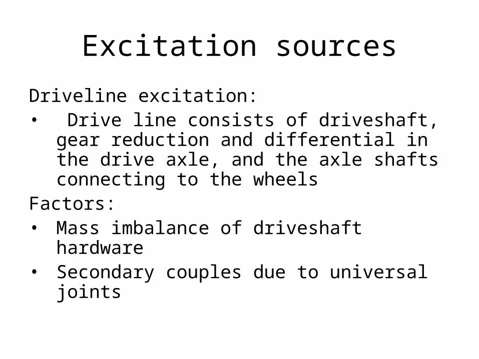
Driveline excitation:• Drive line consists of driveshaft, gear
reduction and differential in the drive axle, and the axle shafts connecting to the wheels
Factors:• Mass imbalance of driveshaft hardware• Secondary couples due to universal
joints
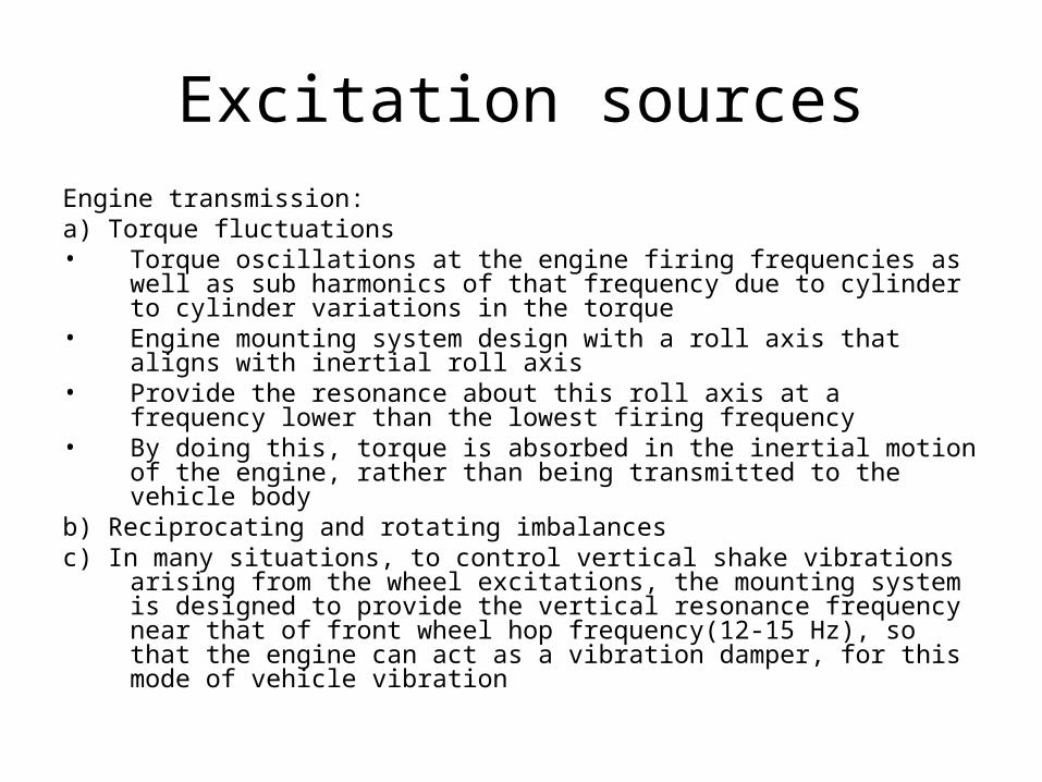
Excitation sourcesEngine transmission: a) Torque fluctuations• Torque oscillations at the engine firing frequencies as well as sub
harmonics of that frequency due to cylinder to cylinder variations in the torque
• Engine mounting system design with a roll axis that aligns with inertial roll axis
• Provide the resonance about this roll axis at a frequency lower than the lowest firing frequency
• By doing this, torque is absorbed in the inertial motion of the engine, rather than being transmitted to the vehicle body
b) Reciprocating and rotating imbalancesc) In many situations, to control vertical shake vibrations arising from the wheel
excitations, the mounting system is designed to provide the vertical resonance frequency near that of front wheel hop frequency(12-15 Hz), so that the engine can act as a vibration damper, for this mode of vehicle vibration
Unsprung mass:• Unsprung mass includes the mass of the tires, brakes, suspension
linkages and other components that move in unison with the wheels. • These components are on the roadway side of the springs and
therefore react to roadway irregularities with no damping, other than the pneumatic resilience of the tires.
Sprung mass:• Rest of the mass is on the vehicle side of the springs and therefore
comprises the sprung mass. • Disturbances from the road are filtered by the suspension system
and as a result are not fully experienced by the sprung mass.
Vehicle Response Properties
Vehicle Response Properties
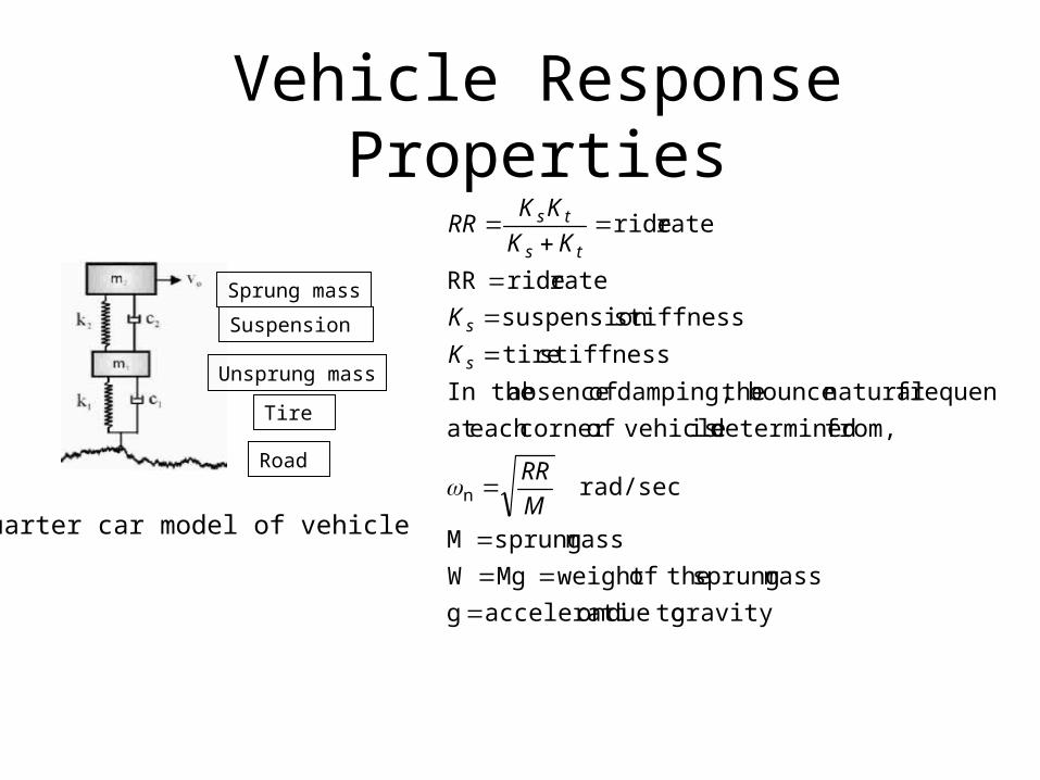
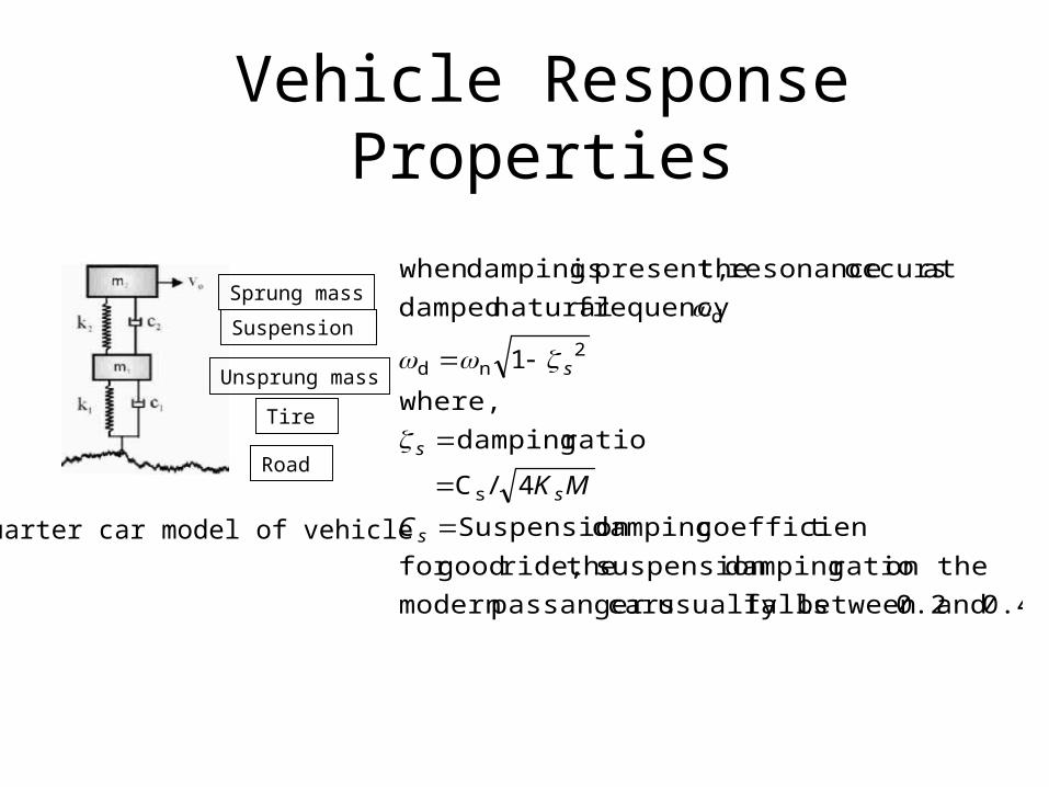
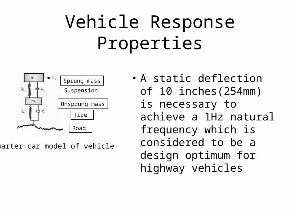
Quarter car model of vehicle
Sprung mass
Suspension
Unsprung mass
Tire
Road
gravity todueon acceleratig
mass sprung theofweight MgW
mass sprungM
rad/sec
from, determined is vehicleofcorner each at
frequency natural bounce thedamping, of absence In the
stiffness tire
stiffness suspension
rate rideRR
rate ride
n
M
RR
K
K
KK
KKRR
s
s
ts
ts
Vehicle Response Properties
Quarter car model of vehicle
Sprung mass
Suspension
Unsprung mass
Tire
Road
0.4 and 0.2between fallsusually carspassanger modern
on the ratio damping suspension theride, goodfor
tcoefficien damping Suspension
4/C
ratio damping
where,
1
frequency natural damped
at occurs resonance thepresent, is dampingwhen
s
2nd
d
s
s
s
s
C
MK
Vehicle Response Properties
Quarter car model of vehicle
Sprung mass
Suspension
Unsprung mass
Tire
Road
• A static deflection of 10 inches(254mm) is necessary to achieve a 1Hz natural frequency which is considered to be a design optimum for highway vehicles
Vehicle Response Properties• At frequencies near 1Hz, the sprung mass is resonating
on the suspension and the road inputs are amplified.• The amplitude ratio at this condition is very sensitive to
damping and for typical passanger cars it is in the range of 1.5 to 3
• For heavy trucks it may reach levels as high as 5 to 6• Above resonance, the road inputs are attenuated
increasingly.• In the range of 10 to 12 Hz, the unsprung mass of the
tire wheel assembly goes in to vertical hop resonance
Vehicle Response Properties• The body resonance behaviour near 1 Hz is unaffected by
unsprung mass changes.• However, above the body resonance, a heavier unsprung
mass pulls the wheel hop resonance frequency down near 7 Hz, greatly increasing the transmission of road inputs in this range, results in ride degradation
• With a lighter unsprung mass, the wheel hop resonant frequency is pushed higher, providing better isolation in the mid frequency range
• It is easier to isolate high frequency vibration elsewhere in the chassis, hence the lighter unsprung mass will generally produce better ride performance
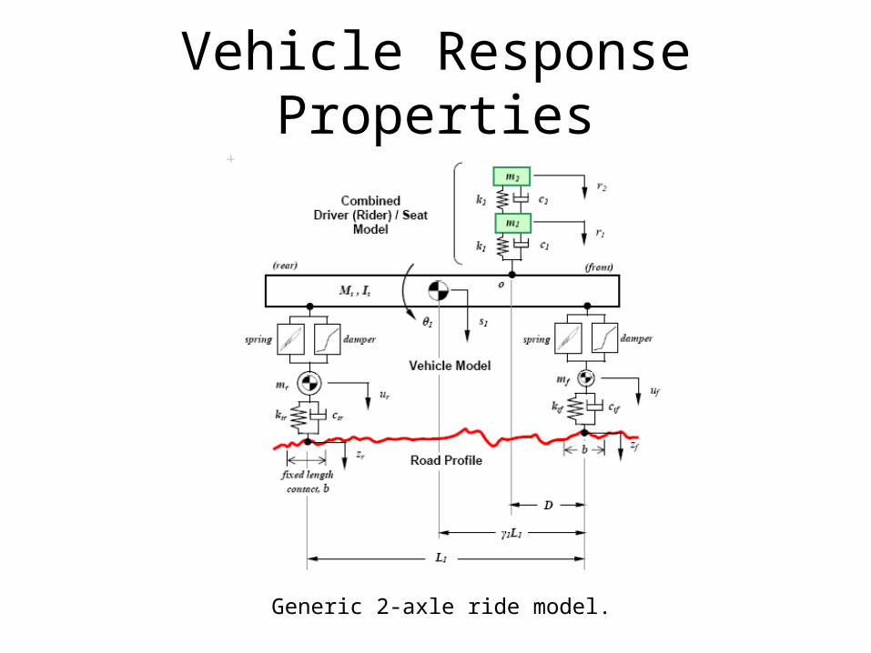
Generic 2-axle ride model.
Vehicle Response Properties
Ride and Vibrations
• To improve the ride quality, the vibrations of a vehicle body should be reduced.
• The low- frequency vibrations are mainly caused by the disturbance from the road. Various kinds of active/passive controlled suspension systems that absorb vertical vibration of the chassis to reduce ride discomfort have been proposed. Most of these studies focus on the vibration of the vehicle chassis, seats and passenger bodies that depend mainly on the mechanical characteristics of vehicles and road paving.
• The relatively high-frequency (20-40Hz) vibrations, which are mainly caused by the engine idle speed, may induce uncomfortable shake and noise in the vehicle cabin.
• The engine vibrations are mainly caused by the reciprocating mechanism in the engine. The frequency of these vibrations is determined by the engine speed.
• The engine vibrations are transmitted to the body structure through the engine mounts. These vibrations excite the vibration modes of the vehicle body panels to induce shake and noise. On the other hand, the velocity fluctuation is an important factor of ride discomfort.
• As the vehicle is a complex multi-body system, subsystems also have vibrations which even couple with each other to influence full vehicle vibration.
• To study vehicle vibration effectively, considering all excitations, it is essential to carry simulation analyses on full vehicle vibration by means of the modern simulation technology.
Ride and Vibrations
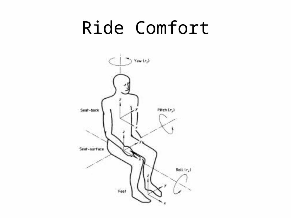
Ride Comfort
Comfort:• Comfort can be defined as the absence of significantly
disturbing or intrusive physical factors. • It is a complex subjective entity depending upon the
effective summation all the physical factors present in the induced environment, as well as upon individual sensitivity to those factors and their summation, and such psychological factors as expectation.
• For these reasons, for example, the same values of vibration that might be judged by most riders to be uncomfortable in a limousine may be judged acceptably comfortable in a bus.
Ride Comfort
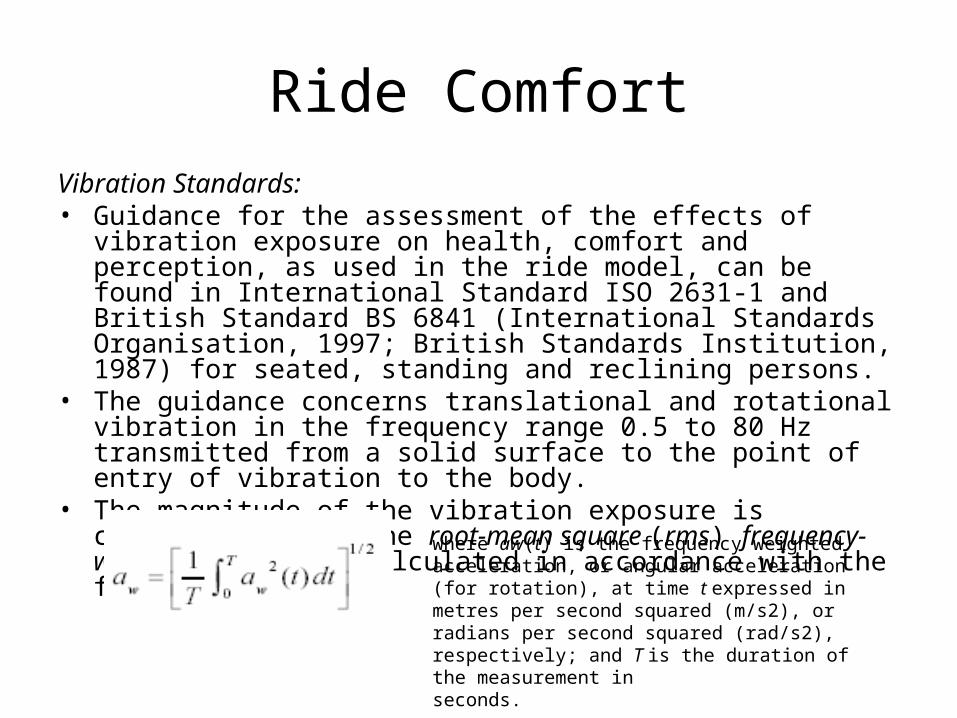
Vibration Standards: • Guidance for the assessment of the effects of vibration exposure on
health, comfort and perception, as used in the ride model, can be found in International Standard ISO 2631-1 and British Standard BS 6841 (International Standards Organisation, 1997; British Standards Institution, 1987) for seated, standing and reclining persons.
• The guidance concerns translational and rotational vibration in the frequency range 0.5 to 80 Hz transmitted from a solid surface to the point of entry of vibration to the body.
• The magnitude of the vibration exposure is characterised by the root-mean square (rms) frequency-weighted acceleration calculated in accordance with the following equation:
Ride Comfort
where aw(t) is the frequency weighted acceleration, or angular acceleration (for rotation), at time t expressed in metres per second squared (m/s2), or radians per second squared (rad/s2), respectively; and T is the duration of the measurement inseconds.
Ride Quality Measure: • The ride quality indicator used in this application is a
direct measure of the major component of ride vibration that is responsible for discomfort due to whole-of-body vertical motions. The ride measure is based on estimation of vertical vibration at the point where it enters the body from the seat cushion at the principal contact area.
• The primary quantity for expressing vibration magnitude is the frequency-weighted root-mean-square (rms) acceleration for vertical (z-direction) translational vibration, azw, defined above in Eqn .
Ride Comfort
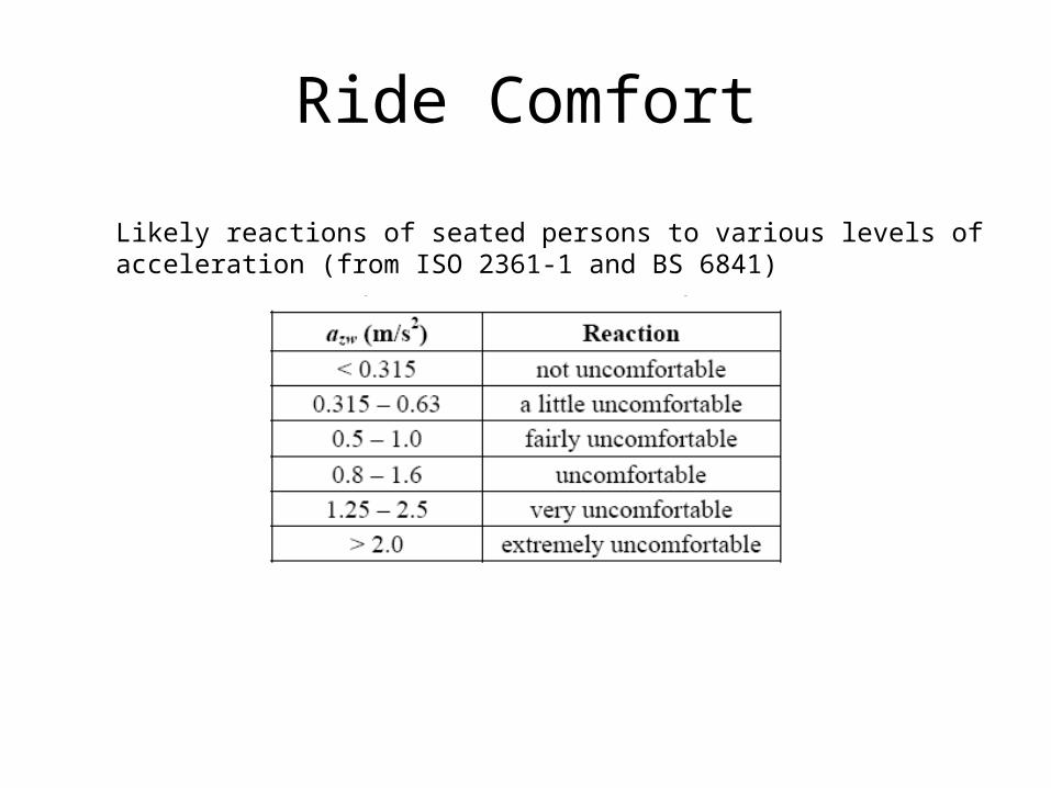
Likely reactions of seated persons to various levels of acceleration (from ISO 2361-1 and BS 6841)
Ride Comfort
Ride comfort
• The quality referred to as "ride comfort" is affected by a variety of factors, including high frequency vibrations, body booming, body roll and pitch, as well as the vertical spring action normally associated with a smooth ride.
• The ride quality normally associated with the vehicle's response to bumps is a factor of the relatively low frequency bounce and rebound movements of the suspension system.
Ride Comfort
Ride Comfort

Ride comfort
• Ride is perceived as most comfortable when the natural frequency is in the range of 1 Hz to 1.5 Hz. When the frequency approaches 2 Hz, occupants perceive the ride as harsh.
Ride comfort
• A frequency in the range of 0.5 to 0.9Hz will produce motion sickness.
• The visceral region of the body objects to frequencies between 5 to 7 Hz.
• The head and neck regions are especially sensitive to vibrations of 18 to 20 Hz.
• Humans are most uncomfortable with longitudinal vibrations in the 1 to 2 Hz range (the region of greatest comfort for vertical vibrations).
• Discomfort from longitudinal disturbances occur when the vehicle pitches or when the seats lean rearward at a higher-than-normal angle.
Ride comfort
• A "good ride" depends on the overall design of the vehicle, rather than just the design of the suspension system.
• To produce a comfortable ride, the high-frequency vibrations of wind and drivetrain noise must be minimized and properly isolated, and the suspension must be set in appropriate rubber mountings to isolate high-frequency roadway-induced vibrations.
• The natural frequency of the suspension system is considered the most important parameter of a comfortable ride.

Automotive NVH Concerns
• Key Vehicle Modes– Body
• Overall Body bending and torsion modes• Instrument panel vibration modes• Steering column• Seats
– Chassis• Suspension Hop (in-phase vertical) and Tramp (out-of-phase
vertical)• Other suspension modes (e.g. fore-aft modes)• Frame bending (on frame vehicles)
– Powertrain• Powertrain bounce, pitch, roll • Powertrain bending, propeller shaft bending• Exhaust bending

NVH Treatments
• Minimize source amplitude– Minimize imbalances– Eliminate pure tones
NVH Treatments
• Minimize path sensitivity– Structural changes
• often difficult to implement late in the design process
– Impedance mismatch• Isolators
– Mass effects (add mass)– Barriers– Absorbers– Mode separation– Dynamic absorbers
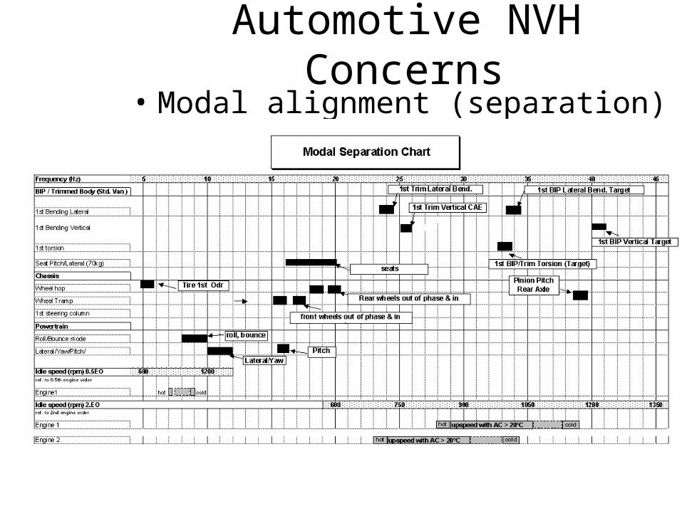
Automotive NVH Concerns• Modal alignment (separation)
Ride comfort
To conclude….• The ride engineer’s goal should be to
eliminate all vibrations in a vehicle. (although impossible!)
• However, elimination of all vibrations is also undesirable because vibrations provide a source of road feel, which is considered to be the essential feedback to the driver…


