Embed Size (px)
DESCRIPTION
Service manual ricoh SP1000
Citation preview

Model PN-C1L Machine Code: B279
Model PN-C1 Machine Code: B299
SERVICE MANUAL
29th Sep. 2006Subject to change

Safety Notice
Important Safety Notices
Prevention of Physical Injury
1. Be sure that the power cord is unplugged before disassembling or assembling parts of the copier orperipherals.
2. The wall outlet should be near the copier and easily accessible.
3. Note that electrical voltage is supplied to some components of the copier and the paper tray unit evenwhile the main power switch is off.
4. If you start a job before the copier completes the warm-up or initializing period, keep hands awayfrom the mechanical and electrical components until job execution has started. The copier will startmaking copies as soon as warm-up or initialization is finished.
5. The inside and the metal parts of the fusing unit become extremely hot while the copier is operating.Be careful to avoid touching those components with your bare hands.
Health Safety Conditions
Toner and developer are nontoxic, but getting either of these into your eyes may cause temporary eyediscomfort. Try to remove with eye drops or flush with water. If material remains in eye or if discomfortcontinues, get medical attention.
• Keep the machine away from flammable liquids, gases, and aerosols. A fire or an explosion mightoccur if this precaution is not observed.
Safe and Ecological Disposal
1. Do not incinerate toner bottles or used toner. Toner dust may ignite suddenly if exposed to an openflame.
2. Dispose of used toner, developer, and organic photoconductors in accordance with local regulations.(These are nontoxic supplies.)
3. Dispose of replaced parts in accordance with local regulations.
1

Laser Safety
The Center for Devices and Radiological Health (CDRH) prohibits the repair of laser-based optical unitsin the field. The optical housing unit can only be repaired in a factory or at a location with the requisiteequipment. The laser subsystem is replaceable in the field by a qualified Customer Engineer. The laserchassis is not repairable in the field. Customer engineers are therefore directed to return all chassis andlaser subsystems to the factory or service depot when replacement of the optical subsystem is required.
• Use of controls not specified in this manual, or performance of adjustments or procedures not specifiedin this manual, may result in hazardous radiation exposure.
WARNING FOR LASER UNIT
• Turn off the main switch before attempting any of the procedures in the Laser Unit section. Laserbeams can seriously damage your eyes.
CAUTION MARKING:
Symbols and Abbreviations
This manual uses several symbols and abbreviations. The meaning of those symbols and abbreviations isas follows:
* See or Refer to
c Clip ring
e E-ring
s Screw
h Connector
2

g Clamp
SEF Short Edge Feed
LEF Long Edge Feed
K Core Technology manual
Cautions, Notes, etc.
The following headings provide special information:
• FAILURE TO OBEY WARNING INFORMATION COULD RESULT IN SERIOUS INJURY OR DEATH.
• Obey these guidelines to ensure safe operation and prevent minor injuries.
• This information provides tips and advice about how to best service the machine.
3

TABLE OF CONTENTSSafety Notice......................................................................................................................................................1
Important Safety Notices...............................................................................................................................1
Laser Safety.....................................................................................................................................................2
Symbols and Abbreviations...........................................................................................................................2
1. Installation
Installation Procedure.........................................................................................................................................9
2. Preventive Maintenance
PM Tables.........................................................................................................................................................11
Cleaning............................................................................................................................................................12
Paper Transport Rollers...............................................................................................................................12
Paper Separator Module............................................................................................................................13
CIS and Flatbed Window...........................................................................................................................13
Front Panel Keys and Covers......................................................................................................................13
3. Replacement and Adjustment
General Precautions on Disassembly.............................................................................................................15
General Precautions....................................................................................................................................15
Replacement Worksheet Chart.......................................................................................................................17
Operation Panel...............................................................................................................................................18
ADF Scanner Cover and White Panel............................................................................................................19
White Panel..................................................................................................................................................19
ADF Scanner Cover.....................................................................................................................................19
Front Door and Side Covers............................................................................................................................23
Front Door ...................................................................................................................................................23
Side Covers .................................................................................................................................................23
ADF Assembly..................................................................................................................................................25
Feeder Assembly..........................................................................................................................................25
Friction Pad and Cork Pad..........................................................................................................................26
Inside Paper Path Assembly........................................................................................................................27
Upper Paper Guide Assembly....................................................................................................................29
Motor Frame................................................................................................................................................30
Motor............................................................................................................................................................31
Scan Path Guide/ Analysis Roller/ Antistatic Brush/ ADF Sliders.........................................................31
CPU Board........................................................................................................................................................35
4

Speaker.............................................................................................................................................................37
Scanner Assembly............................................................................................................................................38
Flatbed Scanner...........................................................................................................................................38
Scanner Frame.............................................................................................................................................39
CIS.................................................................................................................................................................41
CIS Flat Cable..............................................................................................................................................42
CIS Slide.......................................................................................................................................................43
Scanner Motor.............................................................................................................................................44
Back Cover.......................................................................................................................................................46
Middle Frame...................................................................................................................................................47
Paper Cassette..................................................................................................................................................48
Paper Cassette, Side Fence, Bottom Plate and Friction Pad....................................................................48
Laser Unit..........................................................................................................................................................50
Fusing Area.......................................................................................................................................................52
Fusing Unit....................................................................................................................................................52
Paper Exit Assembly.....................................................................................................................................53
Fusing Lamp and Hot Roller........................................................................................................................53
Pressure Roller..............................................................................................................................................56
Thermistor.....................................................................................................................................................57
Hot Roller Strippers......................................................................................................................................57
Thermostat....................................................................................................................................................58
Paper Feed........................................................................................................................................................59
Paper Feed Roller........................................................................................................................................59
Registration Roller .......................................................................................................................................60
Others................................................................................................................................................................62
Transfer Roller..............................................................................................................................................62
Fan Motor.....................................................................................................................................................62
Main Motor..................................................................................................................................................63
PSU (Power Supply Unit).................................................................................................................................65
4. Troubleshooting
Paper Jam.........................................................................................................................................................67
Paper Jam 1.................................................................................................................................................67
Paper Jam 2.................................................................................................................................................70
5

Print Quality......................................................................................................................................................74
Blank Copies................................................................................................................................................74
Black Copies................................................................................................................................................74
Dirty Back Ground.......................................................................................................................................75
Uneven Image Density................................................................................................................................76
Vertical Black Lines......................................................................................................................................77
Horizontal Black Lines.................................................................................................................................78
Vertical White Lines.....................................................................................................................................79
Horizontal White Lines................................................................................................................................80
Black Dots/Spots.........................................................................................................................................81
White Spots in Black Image Areas.............................................................................................................82
Faint Copies..................................................................................................................................................83
Vertical Black Band.....................................................................................................................................84
Unfused Copies............................................................................................................................................84
Ghost Image.................................................................................................................................................85
Toner on the Back of the Printer Paper.......................................................................................................85
Error Code........................................................................................................................................................87
Communication Error Codes.......................................................................................................................87
General Codes............................................................................................................................................87
5. Service Tables
User Mode........................................................................................................................................................91
Tech Mode........................................................................................................................................................92
How to go into Tech Mode.........................................................................................................................92
Installation Parameters................................................................................................................................92
List of Configurations (SOS)........................................................................................................................92
Administrator Functions.............................................................................................................................104
New Cartridge..........................................................................................................................................106
Firmware Download......................................................................................................................................109
Via PC Connection....................................................................................................................................109
Downloading with the Miniboot..............................................................................................................110
Reminders...................................................................................................................................................111
Storing User Parameters................................................................................................................................112
6. Detailed Descriptions
6

Component Layout........................................................................................................................................113
Mechanical Components.........................................................................................................................113
Printing............................................................................................................................................................115
Printing Processes around the Drum.........................................................................................................115
Charge.......................................................................................................................................................116
Laser Exposure...........................................................................................................................................117
Development..............................................................................................................................................119
Transfer and Separation...........................................................................................................................120
Drum Cleaning...........................................................................................................................................121
Paper Feed and Registration....................................................................................................................122
Fusing.........................................................................................................................................................126
Cover Switch .............................................................................................................................................127
Paper Feed Drive Release and Fusing Drive Release.............................................................................128
7. Specifications
General Features...........................................................................................................................................129
Copier........................................................................................................................................................129
Printer..........................................................................................................................................................130
Scanner......................................................................................................................................................130
Fax (B299 only)........................................................................................................................................131
ADF (B299 only).......................................................................................................................................132
Supported Paper............................................................................................................................................133
8. Apppendix
Block Diagram...............................................................................................................................................135
Overview....................................................................................................................................................135
Power Supply.............................................................................................................................................136
Quartz........................................................................................................................................................136
Reset...........................................................................................................................................................137
P-to-P...............................................................................................................................................................138
Operation Panel Card..............................................................................................................................138
CPU Card...................................................................................................................................................140
7

8

1. Installation
Installation ProcedureRefer to the "Operation Instructions for Installation Procedure".
9
1

1. Installation
10
1

2. Preventive Maintenance
PM TablesThere are no PM parts for this machine.
11
2

CleaningTo keep the machine in good working condition, the following operations should be carried out regularly:
• Cleaning the paper transport rollers of the ADF scanner
• Cleaning the paper separator
• Cleaning the CIS window of the flatbed scanner
• Cleaning the front panel keys and the printer covers
• Printer maintenance
• Cleaning the printer with a soft cloth, never use abrasives or detergents
Paper Transport Rollers
1. Set the On/Off switch to Off (position 0).
2. Open the ADF scanner cover.
3. Clean the paper feed roller (pick-up) [A], paper feed roller (feed) [B], feed shafts, and also the twoanalysis rollers [C] located on the mobile part of the scanner, with a lint-free cloth moistened inisopropyl alcohol.
To clean them, rotate them in the same direction as during paper transport.
Recommended interval: from 2 to 6 months, depending on utilization.
2. Preventive Maintenance
12
2

Paper Separator Module
1. Set the On/Off switch to Off (position 0).
2. Open the ADF scanner cover.
3. Disassemble the ADF feeder (* "Inside Paper Path Assembly" in the chapter "Replacement andAdjustment").
4. Wipe the elements of the paper separation pad [A] with a lint-free cloth soaked with isopropyl alcohol.
Recommended interval: from 2 to 6 months, depending on utilization.
CIS and Flatbed Window
1. Set the On/Off switch to Off (position 0).
2. Open the flatbed scanner cover.
3. Clean the CIS window with a lint-free cloth moistened with isopropyl alcohol or use antistatic paperused for cleaning optic glass.
Recommended interval: depending on utilization; it is advisable to make a local copy to check if the windowis clean.
Front Panel Keys and Covers
Cleaning the front panel keys
1. Set the On/off switch to Off (position O).
2. Clean the top of the front panel and the keys with a lint-free cloth moistened with isopropyl alcoholor a spray-on cleaning product.
Cleaning
13
2

3. Leave the product on for a few seconds before wiping it off.
Recommended interval: to be defined depending on utilization.
Cleaning the covers
It is advisable to clean all the covers during a maintenance visit.
1. Set the On/Off switch to Off (position O).
2. Clean the external areas of the covers with a lint-free cloth moistened with isopropyl alcohol or aspray-on cleaning product.
3. Leave the product on for a few seconds before wiping it off.
2. Preventive Maintenance
14
2

3. Replacement and Adjustment
General Precautions on Disassembly
General Precautions
Use high caution when you disassemble and reassemble components.
Make sure all cables are correctly routed. Check the correct cable routing before you service the machine.Return all cables to their original position after you service the machine.
Servicing the Machine
1. Make sure there are not documents stored in memory before you service the machine.
2. Remove the toner cartridge before you disassemble parts.
3. Unplug the power cord before you service the machine.
4. Use a flat clean surface to service the machine.
5. Use only approved replacement parts. Machine function cannot be guaranteed of you useunauthorized replacement parts.
6. Do not force plastic components.
7. Make sure all components are in their correct positions.
Releasing Plastic Latches
15
3

Many of the parts are held in place with plastic latches. The latches break easily. Release them carefully.To remove such parts, press the hook end of the latch away from the part to which it is latched.
3. Replacement and Adjustment
16
3

Replacement Worksheet ChartWhen you replace a unit, refer to the flowchart as shown below to confirm the steps.
Replacement Worksheet Chart
17
3

Operation Panel1. Stand in front of the machine.
2. Unlock the three clips of the operation panel ([A], [B] and [C]).
3. Pull the panel towards yourself to release it from the two bottom slots ([D] and [E]).
4. Disconnect the flat panel cable [F] from the panel card connector.
5. Disassemble the operation panel.
3. Replacement and Adjustment
18
3

ADF Scanner Cover and White Panel
White Panel
1. Stand in front of the machine and open the ADF scanner cover [A].
2. Pull out the white panel [B] located inside the ADF scanner cover.
ADF Scanner Cover
<B299 only>
1. Open the ADF cover [A].
ADF Scanner Cover and White Panel
19
3

2. Remove the ADF motor cover [B] from its two slots using a flat screwdriver then disassemble the ADFmotor cover.
3. Unscrew the mounting screw [C] of the ground cable.
4. Disconnect the ADF scanner cover sensor connector [D] and the paper sensor connector [E].
3. Replacement and Adjustment
20
3
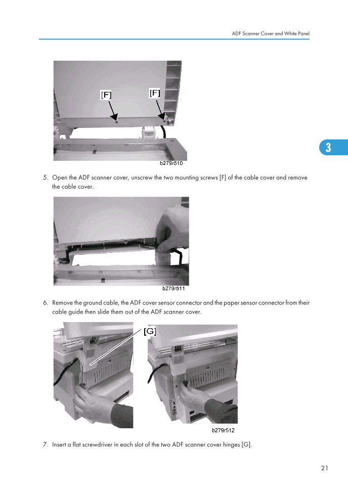
5. Open the ADF scanner cover, unscrew the two mounting screws [F] of the cable cover and removethe cable cover.
6. Remove the ground cable, the ADF cover sensor connector and the paper sensor connector from theircable guide then slide them out of the ADF scanner cover.
7. Insert a flat screwdriver in each slot of the two ADF scanner cover hinges [G].
ADF Scanner Cover and White Panel
21
3

8. Lift and remove the ADF scanner cover, do not forget the mounting screws of the hinges.
3. Replacement and Adjustment
22
3

Front Door and Side Covers
Front Door
1. Stand in front of the machine.
2. Push the left and right sides [A] of the front door and simultaneously pull it towards yourself.
3. Move the arms away from each other and remove the front door [B].
Side Covers
1. Open the printer’s paper tray.
2. Unscrew the two mounting screws on the front [A] and back [B] of the side covers (right and left).
Front Door and Side Covers
23
3

3. Using a flat screwdriver, unscrew the side covers from their slots [C] located at the bottom of themachine.
4. Unclip the side covers [D] from the top slots located at the back of the machine and pivot them towardsyourself to remove them.
5. Remove the side covers.
3. Replacement and Adjustment
24
3

ADF Assembly
Feeder Assembly
<B299 only>
1. Open the ADF cover [A].
2. Lift the roller bearing [B].
ADF Assembly
25
3

3. Lift the roller bearing [C] from the other end of the feeder.
4. Lift the feeder assembly [D] and remove the feeder.
Friction Pad and Cork Pad
Friction Pad
<B299 only>
1. Feeder assembly (* "Feeder assembly")
2. Insert a screwdriver in the right slot [A] as shown above and make a pivoting movement downwardswithout strain to remove the friction pad.
3. Repeat the previous step for the left slot [B] of the friction pad.
4. Remove the friction pad [C], the feeder shoe [D] and the friction pad spring [E].
3. Replacement and Adjustment
26
3

Cork Pad
1. Feeder assembly (* "Feeder assembly")
2. Insert a screwdriver in the right slot on the upper part of the ADF scanner as shown above and makea pivoting movement downwards without strain to remove the cork pad [A].
3. Remove the cork pad [A].
Inside Paper Path Assembly
<B299 only>
1. Lift the ADF cover and unscrew the two mounting screws [A] of the inside paper path assembly.
ADF Assembly
27
3
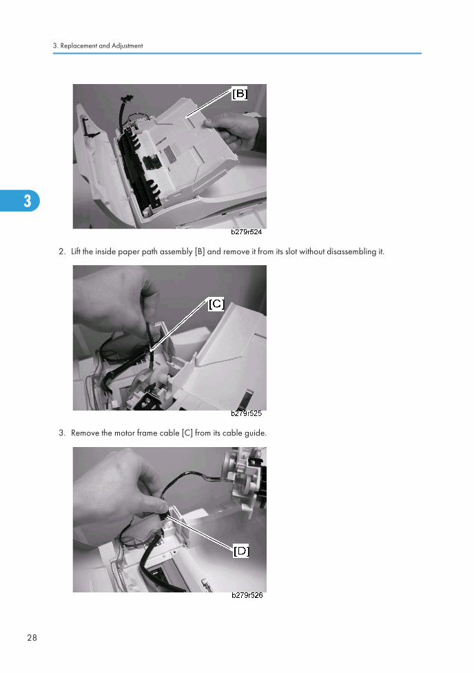
2. Lift the inside paper path assembly [B] and remove it from its slot without disassembling it.
3. Remove the motor frame cable [C] from its cable guide.
3. Replacement and Adjustment
28
3

4. Disconnect the connector [D] reaching the ADF cover and remove the inside paper path assembly.
Upper Paper Guide Assembly
<B299 only>
1. Feeder assembly (* "Feeder assembly")
2. Open the ADF cover.
3. Unscrew the two mounting screws [A] of the paper guide assembly.
4. Make a forward movement and remove the paper guide assembly [B].
ADF Assembly
29
3

Motor Frame
<B299 only>
1. Inside paper path assembly (* "Inside Paper Path Assembly")
2. Unscrew the mounting screw [A] of the motor frame.
3. Lift and remove the motor frame [B]. Locate the gears and remove them.
3. Replacement and Adjustment
30
3

Motor
<B299 only>
1. Motor Frame (* "Motor Frame)
2. Unscrew the two mounting screws [A] of the motor and remove the motor.
Scan Path Guide/ Analysis Roller/ Antistatic Brush/ ADF Sliders
Scan path guide
<B299 only>
1. Inside paper path assembly (* "Inside Paper Path Assembly")
2. Motor frame for analysis rollers (* "Motor Frame")
ADF Assembly
31
3

3. Turn the inside paper path assembly [A] upside down.
4. Lift the scan path guide [B] to disassemble it from the inside paper path assembly and remove it.
Analysis Roller
1. Inside paper path assembly (* "Inside Paper Path Assembly")
2. Motor frame for analysis rollers (* "Motor Frame")
3. Turn the inside paper path assembly [A] upside down.
4. Lift the roller bearing [B] turning of each one of the analysis rollers.
5. Remove the roller bearing turnings of the analysis rollers and remove the analysis rollers [C].
ADF Sliders and Antistatic Brush
1. Inside paper path assembly (* "Inside Paper Path Assembly")
2. Motor frame for analysis rollers (* "Motor Frame")
3. Replacement and Adjustment
32
3

3. Turn the inside paper path assembly [A] upside down.
4. Unscrew the two mounting screws of the ADF wheelbox [B] and remove it.
5. Vertically lift the ADF sliders [C] and remove them from the inside paper path assembly.
ADF Assembly
33
3

6. Remove gently the antistatic brush [D].
3. Replacement and Adjustment
34
3

CPU Board
• Before replacing the CPU board, do the "Replacing the CPU Board" in the section "AdministratorFunctions" at the chapter "Service Tables".
1. Front door and the right side cover (* "Front Door and Side Covers")
2. Unscrew the three mounting screws of the CPU board plate [A].
3. Pull the CPU board plate [A] towards yourself and remove it.
CPU Board
35
3

4. Unscrew the mounting screw [B] of the CPU board connector and disconnect it.
5. Disconnect all incoming cords and leads from the CPU board connectors.
• MEMORIZE ALL CONNECTIONS FOR REASSEMBLY.
6. Unscrew the eight mounting screws and remove the CPU board [C].
3. Replacement and Adjustment
36
3

Speaker1. Front door and the right-hand side cover (* "Front Door and Side Covers")
2. CPU board plate (* "CPU Board")
3. Disconnect the speaker connector [A] from the CPU board.
4. Remove the speaker connector from its ferrite tube and cable guide.
• MEMORIZE THE CABLE GUIDE FOR REASSEMBLY.
5. Press the top clip [B] inwards until it unclips and pull the speaker [C] towards yourself.
6. Remove the speaker.
Speaker
37
3

Scanner Assembly
Flatbed Scanner
• Before replacing the flatbed scanner, do the "Replacing the scanner" in the section "AdministratorFunctions" at the chapter "Service Tables".
1. Flatbed scanner cover (* "ADF Scanner Cover and White Panel")
2. Front door and the side covers (*"Front Door and Side Covers")
3. CPU board plate (* "CPU Board")
4. Disconnect the scanner connector [A] from the CPU board and remove it from its ferrite tube and cableguide.
5. Disconnect the operation panel flat cable [B] and the CIS flat cable [C] from the CPU board.
• MEMORIZE THE CONNECTIONS FOR REASSEMBLY.
6. Remove the operation panel and CIS flat cables from their cable guides.
• MEMORIZE THE CONNECTIONS FOR REASSEMBLY.
3. Replacement and Adjustment
38
3
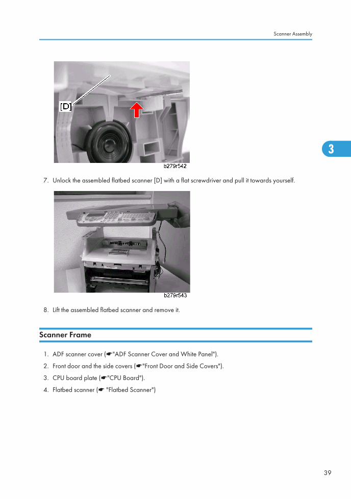
7. Unlock the assembled flatbed scanner [D] with a flat screwdriver and pull it towards yourself.
8. Lift the assembled flatbed scanner and remove it.
Scanner Frame
1. ADF scanner cover (*"ADF Scanner Cover and White Panel").
2. Front door and the side covers (*"Front Door and Side Covers").
3. CPU board plate (*"CPU Board").
4. Flatbed scanner (* "Flatbed Scanner")
Scanner Assembly
39
3

5. Unscrew the two mounting screws [A] [B] on the scanner, and turn the scanner upside down.
6. Unscrew the seven mounting screws at the back of the equipped scanner and turn it upside down.
3. Replacement and Adjustment
40
3

7. Lift the front part of the scanner frame [C] and remove it.
CIS
1. ADF scanner cover (*"ADF Scanner Cover and White Panel").
2. Front door and the side covers (*"Front Door and Side Covers").
3. CPU board plate (*"CPU Board").
4. Flatbed scanner (* "Flatbed Scanner")
5. Lift the CIS [A] backwards.
Scanner Assembly
41
3

6. Disconnect the CIS flat cable [B] and release the CIS from its two side slots.
• KEEP THE CIS SUPPORT SPRINGS AND CIS SLIDES.
7. Remove the CIS.
CIS Flat Cable
1. ADF scanner cover (*"ADF Scanner Cover and White Panel").
2. Front door and the side covers (*"Front Door and Side Covers").
3. CPU board plate (*"CPU Board").
4. Flatbed scanner (* "Flatbed Scanner")
5. Release the end of the CIS flat cable [A] and remove it from its slot.
3. Replacement and Adjustment
42
3

6. Slide the CIS flat cable out of its ferrite tube which is fixed to the CIS panel and remove it from thescanner.
7. Remove the CIS flat cable from its cable guides located above and below the scanner bottom thenslide it to extract it from the scanner bottom.
• MEMORIZE THE CABLE GUIDE FOR REASSEMBLY.
8. Remove the CIS flat cable.
CIS Slide
1. ADF scanner cover (*"ADF Scanner Cover and White Panel").
2. Front door and the side covers (*"Front Door and Side Covers").
3. CPU board plate (*"CPU Board").
4. Flatbed scanner (* "Flatbed Scanner")
5. Lift the CIS drive pulley [A] and the drive belt to extract the CIS drive pulley from its slot.
Scanner Assembly
43
3

6. Remove the drive belt [B] from the drive pulley.
7. Lift then disassemble the CIS slide [C].
Scanner Motor
1. ADF scanner cover (*"ADF Scanner Cover and White Panel").
2. Front door and the side covers (*"Front Door and Side Covers").
3. CPU board plate (*"CPU Board").
4. Flatbed scanner (* "Flatbed Scanner")
5. Unscrew the two mounting screws [A] [B] of the scanner motor [C].
3. Replacement and Adjustment
44
3

6. Remove the end of the scanner motor connector [D] from its ferrite tube.
7. Remove the CIS motor connector from its cable guide.
8. Remove the scanner motor [C].
Scanner Assembly
45
3

Back Cover1. ADF scanner cover (*"ADF Scanner Cover and White Panel").
2. Front door and the side covers (*"Front Door and Side Covers").
3. CPU board plate (*"CPU Board").
4. Flatbed scanner (* "Flatbed Scanner")
5. Stand behind the machine.
6. Unscrew the two back mounting screws [A] [B] on the back cover [C].
7. Unscrew the two top mounting screws [D] [E] on the back cover.
8. Pull the back cover [C] towards yourself and remove it.
3. Replacement and Adjustment
46
3

Middle Frame1. ADF scanner cover (*"ADF Scanner Cover and White Panel").
2. Front door and the side covers (*"Front Door and Side Covers").
3. CPU board plate (*"CPU Board").
4. Speaker (* "Speaker")
5. Flatbed scanner (* "Flatbed Scanner")
6. Back cover (* "Back Cover")
7. Unscrew the two mounting screws on the left and right side on the middle frame.
8. Lift and remove the middle frame [A].
Middle Frame
47
3

Paper Cassette
Paper Cassette, Side Fence, Bottom Plate and Friction Pad
1. Pull out the paper cassette [A]
2. Side fence gear [B]
3. Side fence – Left [C] (hook)
4. Side fence – Right [D] (hook)
• Lift the bottom plate before removing the side fences.
3. Replacement and Adjustment
48
3

5. Bottom plate [E]
6. Unhook the hook [F] at both sides of the cassette.
7. Detach from the pin [G] at both sides.
8. Friction pad [H] (two hooks)
• Be careful not to lose the spring [I].
Paper Cassette
49
3

Laser Unit
• This machine contains a laser beam generator. Laser beams can cause permanent eye damage. Donot open the laser unit or look along the laser beam path while the main power is on.
1. Front door and side covers (* "Front Door and Side Covers")
2. Back cover (* "Back Cover")
3. Flatbed scanner assembly (* "Flatbed Scanner Assembly")
4. Upper unit. (* "Upper Unit")
5. Laser diode unit harness [A]
6. Polygon mirror motor harness [B]
7. Laser unit [C] (s x 3)
Caution Decal: [D]
3. Replacement and Adjustment
50
3

• When re-assembling, make sure to set the positioning pin [E] in the hole [F].
Laser Unit
51
3

Fusing Area
Fusing Unit
1. Front door and side covers (* "Front Door and Side Covers")
2. Back cover (* "Back Cover")
3. Flatbed scanner assembly (* "Flatbed Scanner Assembly")
4. Upper unit (* "Upper Unit")
5. Thermistor harness [A]
6. Paper exit sensor harness [B]
7. Fusing lamp harness [C]
8. Fusing unit [D] (s x 4)
3. Replacement and Adjustment
52
3

Paper Exit Assembly
1. Fusing cover [A] (s x 1)
2. Paper exit assembly [B] (s x 2)
Fusing Lamp and Hot Roller
Fusing Lamp
1. Paper exit assembly (* "Paper Exit Assembly").
Fusing Area
53
3

2. Remove two screws (s x 2)
3. Fusing lamp [A]
• Do not touch the surface of the fusing lamp with bare hands.
Reassembly
3. Replacement and Adjustment
54
3

When reassembling, be careful to set the fusing lamp on the frame first, then set the terminals [B] and [C].
Hot Roller
1. Electrode [A] (s x 1)
Fusing Area
55
3

2. Hot roller [B] (pull it out)
• Do not touch the surface of the hot roller with bare hands.
• When reassembling, be careful not to damage the hot roller strippers [C].
Pressure Roller
1. Paper exit assembly (* "Paper Exit Assembly)
2. Fusing lamp and hot roller (* "Fusing Lamp and Hot Roller)
3. Pressure roller [A] (1 bushing [B] and 1 spring [C] at each side)
• When re-assembling, be careful to set the bushing [B] and spring [C] in the correct position.
3. Replacement and Adjustment
56
3

Thermistor
1. Paper exit assembly (* "Paper Exit Assembly)
2. Thermistor [A] (s x 1)
• When reassembling, do not damage the thermistor, and check that the element touches the hotroller.
Hot Roller Strippers
1. Paper exit assembly (* "Paper Exit Assembly)
2. Fusing lamp and hot roller (* "Fusing Lamp and Hot Roller")
3. Hot roller stripper [A] (1 spring [B] each)
Fusing Area
57
3

• When reassembling, be careful not to lose the spring [B].
Thermostat
1. Paper exit assembly (* "Paper Exit Assembly")
2. Fusing lamp and hot roller (* "Fusing Lamp and Hot Roller")
3. Thermostat [A] (s x 2)
3. Replacement and Adjustment
58
3

Paper Feed
Paper Feed Roller
1. Upper unit (* "Upper Unit")
2. Drive assembly [A] (s x 4)
3. Electromagnetic clutch assembly [B] (c x 1)
Paper Feed
59
3
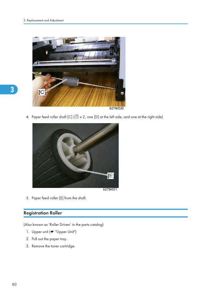
4. Paper feed roller shaft [C] (c x 2, one [D] at the left side, and one at the right side)
5. Paper feed roller [E] from the shaft.
Registration Roller
(Also known as ‘Roller Driven’ in the parts catalog)
1. Upper unit (* "Upper Unit")
2. Pull out the paper tray.
3. Remove the toner cartridge.
3. Replacement and Adjustment
60
3

4. Paper tray guides [A] (s x 2)
5. Left shield [B] (s x 13, s x 2 at the bottom)
6. Right shield [C] (s x 9)
7. Laser shield [D] (s x 4)
8. Guide shield [E] (s x 4)
9. Plate [F] (s x 2)
10. White bushings [G]
11. Registration roller [H] (lift it out)
Paper Feed
61
3

Others
Transfer Roller
1. Open the front door (* "Upper Unit")
2. Remove the toner cartridge.
3. Black bushings [A]
4. Remove the transfer roller [B] with a flat-head (-) screwdriver.
Fan Motor
1. Upper unit (* "Upper Unit")
3. Replacement and Adjustment
62
3

2. Fan motor [A] (s x 1, h x 1)
Main Motor
1. Upper unit (* "Upper Unit")
2. Remove the paper tray.
3. Remove the toner cartridge.
4. Laser unit (* "Laser Unit")
5. Paper tray guides [A] (s x 2)
6. Left shield [B] (s x 13, s x 2 at the bottom)
7. Right shield [C] (s x 9)
8. Laser shield [D] (s x 4)
9. Guide shield [E] (s x 4)
Others
63
3

10. Main motor [F] (s x 3, h x 1)
3. Replacement and Adjustment
64
3

PSU (Power Supply Unit)1. Upper unit (* "Upper Unit")
2. Remove the paper tray.
3. Remove the toner cartridge.
4. Right and left shield (* "Main Motor")
5. PSU [A] (s x 9, h x 4)
PSU (Power Supply Unit)
65
3

3. Replacement and Adjustment
66
3

4. Troubleshooting
Paper Jam
Paper Jam 1
Non-feed
Possible Cause:
1. Use of a non-recommended paper type.
2. The paper cassette end fence is set incorrectly.
3. The paper lift mechanism is not working properly.
4. Malfunction in the paper feed clutch.
5. The paper feed roller is set incorrectly.
6. The paper feed motor is defective.
7. The registration sensor is defective.
Action:
1. Check whether a correct paper type is being used.
2. Check that the paper cassette end fence is set correctly and check the paper lift mechanism.
3. Check the paper lift is working properly.
4. Check that the feed clutch for the cassette is working properly.
5. Check that the paper feed roller is installed properly. Clean or replace if necessary.
6. Check the registration sensor and mechanism. Clean or replace if necessary.
7. Check that the registration sensor is working correctly.
Paper Jam - Inside Printer
Possible Cause:
1. Using a non-recommended type of paper.
2. The paper end fence and/or the paper guides in the cassette are set incorrectly.
3. The registration sensor and is defective.
4. Obstruction in the paper path.
5. The main motor is defective.
Action:
67
4

1. Check whether a correct paper type is being used, and whether the paper end fence and guides areset correctly.
2. Check for obstructions in the paper path.
3. Check that the registration sensor is working properly.
4. Check the obstruction in the paper path.
5. Replace the main motor if necessary.
6. If the problem remains, do the following:
7. Check the connections between board and the main motor.
8. Check the fusing unit drive mechanism. Check to see that the gears are installed correctly.
Jam - Fusing Exit
Possible Cause:
1. Use of a non-recommended type of paper.
2. Obstruction in the paper path.
3. The registration sensor is defective.
4. Malfunction in the fusing drive mechanism.
5. Malfunction in the hot roller stripper(s) mechanism.
6. Malfunction in the pressure mechanism in the fusing unit.
Action:
1. Check whether a correct type of paper is being used.
2. Check for obstructions in the paper path.
3. Check that the registration sensor is working correctly.
4. Check all the gears in the fusing drive mechanism.
5. Check that the fusing exit sensor is working correctly.
6. Check the hot roller strippers and the pressure mechanism in the fusing unit.
Skew
Possible Cause:
1. Use of a non-recommended type of paper.
2. Incorrect positioning of the paper guides in the paper cassette.
3. The friction pad is out of position.
4. The paper feed roller is worn out or damaged.
5. Obstruction in the paper path.
4. Troubleshooting
68
4

6. Malfunction in the registration mechanism.
Action:
1. Check whether a correct type of paper is being used.
2. Check that the paper guides and the end fence are set correctly.
3. Check that the friction pad is set correctly.
4. Check if the paper feed roller is installed correctly and clean. Replace if necessary.
5. Check for obstructions in the paper path.
6. Check the registration mechanism and clean or replace the rollers if necessary.
Multi-feed
Possible Cause:
1. Use of a non-recommended type of paper.
2. Incorrect positioning of the paper guides and/or end fence in the paper cassette.
3. The friction pad is out of position.
Action:
1. Check whether a correct type of paper is being used.
2. Check that the paper guides and the end fence are set correctly.
3. Check that the friction pad is set correctly.
4. Fan the edges of the paper stack to separate the pages. Then tap the stack on a flat surface to evenup.
Paper Jam
69
4

Paper Jam 2
Jam 1. Paper jam at the paper cassette
When the registration sensor does not turn on within 2.65 seconds after the paper pick-up clutch for thepaper cassette turns on.
Action
1. Slide out the paper tray unit.
2. Grab the visible edge of the paper and gently pull it out of the paper tray as shown above. Then makesure the remaining paper on the paper tray unit is correctly aligned.
4. Troubleshooting
70
4

3. Slide the tray back into the machine. Then open and close the front cover. Printing starts again.
Jam 2. Paper did not pass the registration sensor
When the registration sensor does not turn off within the specified time for passing a paper after theregistration sensor turns on.
Action
1. Open the front cover and remove the AIO.
2. Gently pull the paper toward you as shown above.
3. Make sure there is no more paper in the machine.
4. Re-install the AIO and close the cover. Printing starts again.
Jam 3. Paper did not reach the fusing unit
Paper Jam
71
4

When the paper exit sensor does not turn on within 2.1 seconds after the registration sensor turns on.
Action
1. Open the front cover and remove the AIO.
2. Gently pull the paper toward you as shown above.
3. Make sure there is no more paper in the machine.
4. Re-install the AIO and close the cover. Printing starts again.
Jam 4. Paper jam in the fusing exit area
The paper exit sensor does not turn off within 3.0 seconds after the registration sensor turns off.
Action
1. Pull the paper straight out if paper gets jammed when it exits to the output tray. Do not continue to pullthe paper if there is resistance and the paper does not move. In this condition, go to the next step.
2. Open the rear output tray.
3. Loosen the paper if it is caught in the feed rollers. Then gently pull the paper out.
4. Close the rear output tray. Then open and close the front cover. Printing starts again.
• Paper jam in this area is very close to the fusing unit. The fusing unit can get very hot. Use high cautionwhen you remove paper in this area.
4. Troubleshooting
72
4

Jam 5. Paper no feed jam in the bypass tray
When the registration sensor does not turn on within 1.6 seconds after the main motor starts.
Action
Pull the paper straight out if paper gets jammed when it exits rear cover area.
Paper Jam
73
4

Print Quality
Blank Copies
Possible Cause
• Poor drum sensitivity.
• Laser optic components are out of position.
• The proper bias voltages are not applied to the toner application roller and/or the developmentroller.
• The proper current is not applied to the transfer roller.
Action
1. Print a test pattern, and open the cover in the middle of printing.
2. Check to see if there is toner adhered to the drum surface.
If there is, do the following. If not, go to step 3.
• Check to see if the cartridge is correctly installed.
• Check to see if the transfer roller is correctly positioned.
3. Check to see if the cartridge is empty. If it is, replace the cartridge.
Black Copies
Possible Cause
The charge is incorrectly applied.
Action
1. Check the connections between the power supply unit, the charge voltage terminals, and the cartridge.
• If they are OK, go to step 2.
• If not, fix the connections.
2. Replace the power supply unit.
4. Troubleshooting
74
4

Dirty Back Ground
Possible Cause
• Poor drum sensitivity.
• The charge is incorrectly applied.
• The hot roller is dirty.
Action
1. Try replacing the cartridge.
2. Check to see if the hot roller surface is dirty.
• If it is, clean the roller.
• If not, go to step 3.
3. Check whether all connections between the charge bias terminals and the cartridge are correct.
• If they are, check or replace power supply unit.
• If they are not, fix the connections.
Print Quality
75
4

Uneven Image Density
Possible Cause
• Poor drum sensitivity.
• Dirty laser optic components.
• A deformed toner metering blade.
• Uneven toner supply in the toner hopper.
Action
1. Print a solid black test pattern, and open the cover in the middle of printing.
2. If the image is lighter in the center of the image, the toner may be low. Replace the cartridge. If it isnot, go to step 3.
3. Check to see if the toner is evenly distributed on the drum.
• If it is not, check the cartridge and the laser optic components.
• If it is, check if there is any dirt on the transfer roller surface.
4. Troubleshooting
76
4

Vertical Black Lines
Possible Cause
• Damaged cleaning blade.
• Dirty hot roller stripper(s).
Action
1. Replace the cartridge.
2. Clean the hot roller strippers.
Print Quality
77
4

Horizontal Black Lines
Possible Cause
The drum surface is scratched or damaged.
Action
1. Check to see if the surface of the drum is damaged.
• Replace the cartridge if damaged.
4. Troubleshooting
78
4

Vertical White Lines
Possible Cause
• The laser optic components are dirty.
• The hot roller stripper scrapes off toner from the print paper.
• Damaged cleaning blade.
Action
• Clean the laser optic components.
• Check the hot roller stripper mechanism. Clean the strippers and replace them if damaged.
• Replace the cartridge.
Print Quality
79
4

Horizontal White Lines
Possible Cause
• A damaged or deformed development roller surface.
• The development bias is unstable.
• The transfer current is unstable.
Action
1. Print a test pattern, and open the cover in the middle of printing.
2. Check to see if horizontal white lines (where toner is not adhered) appear on the drum surface or not.
• If not, check the transfer roller surface and the transfer bias terminal connections. If they are OK,check or replace the power supply unit.
• Replace the cartridge.
4. Troubleshooting
80
4

Black Dots/Spots
Possible Cause
• The drum surface is damaged (this is likely if the dots appear at 75.3 mm intervals).
Action
• Replace the cartridge.
Print Quality
81
4

White Spots in Black Image Areas
Possible Cause
• The drum surface is damaged (this is likely if the dots appear at 75.3 mm intervals).
• The development roller surface is damaged (this is likely if the dots appear at 36.4 mm intervals).
• The toner application roller surface is damaged (this is likely if the dots appear at about 29.1 mmintervals).
• The transfer roller surface is damaged (this is likely if the dots appear at about 43.9 mm intervals).
• The exposure roller surface is damaged (this is likely if the dots appear at about 37.7 mm intervals).
Action
• Replace the cartridge.
4. Troubleshooting
82
4

Faint Copies
Possible Causes
• Poor drum sensitivity.
• Dirty laser optic components.
• Incorrect development/ transfer bias
• Low toner
• Low fusing temperature
Action
1. Print a test pattern, and open the cover in the middle of printing.
2. Check to see if the toner on the paper at the entrance of the fusing unit appears faint.
• If it does, check or replace the fusing lamp, thermistor, and power supply unit.
• If it does not, go to step 3.
3. Check to see if the toner on the drum looks faint.
• If it does, go to step 4.
• If it does not, check the contacts between the transfer bias terminals and power supply unit.
4. Check all the contacts between the development and toner application rollers' bias terminals.
• If it does not, try replacing the cartridge.
Print Quality
83
4

Vertical Black Band
Possible Cause
• A deformed, damaged, or incorrectly positioned toner metering blade.
Action
• Replace the cartridge.
Unfused Copies
Possible Cause
• The thermistor is defective.
• The spring mechanism for the fusing pressure roller is defective.
• Incorrect toner type.
• Non-recommended paper type.
Action
1. Check that the correct type of paper and toner are in use.
4. Troubleshooting
84
4

• If it is, go to step 2.
• If not, use recommended types of paper and cartridge.
2. Try replacing the fusing lamp and the hot and/or pressure roller.
Ghost Image
Possible Cause
• Poor drum sensitivity.
• The cleaning blade is deformed or incorrectly positioned.
• Dirty hot roller
Action
1. Replace the cartridge.
2. Clean the hot roller surface and/or replace the cleaning pad.
Toner on the Back of the Printer Paper
Possible Cause
• Dirty transfer roller
• Dirty fusing pressure roller
Action
1. Check to see if the transfer roller is dirty with toner.
• If it is, clean the roller surface by copying a sheet of white paper three times or more. (For betterresults, copy one sheet at a time)
• If not, go to step 2.
2. Check to see if the fusing pressure roller is dirty with toner.
• If it is, clean the fusing pressure roller.
• If not, check for any other dirty rollers and clean them.
Incorrectly Aligned Output
Print Quality
85
4
Possible Cause
• Laser optics are aligned incorrectly.
• Incorrect print margin setting (main scan direction).
Action
• Adjust the main scan print margin.
• Check that the laser optics are aligned correctly.
• Replace the Laser unit.
• Replace the main board.
INCORRECTLY ALIGNED OUTPUT/REDUCED IMAGE
Possible Cause
• Incorrect print margin (sub-scan direction).
Action
• Replace the Laser unit.
• Replace the main board.
4. Troubleshooting
86
4

Error Code
Communication Error Codes
The communication error codes appear in the logs (printed using key sequence > "5" > "2") and in thetransmission reports.
General Codes
Code Error Cause Actions
01 Engaged or no fax toneThis code appears after 6 failedattempts.
Restart the transmission at a latertime.
03 Stopped by operatorCommunication stopped by theoperator by pressing the key.
04Programmed numberinvalid
Invalid programmed single-keyor quick-dial number (Example:a delayed transmission hasbeen programmed with a singlekey and this key has beendeleted).
Check the validity of theprogrammed number and/or thesingle-key associated to theprogrammed number.
05 Scanning fault
An incident has occurred at thelocation of the document to betransmitted (Example: the sheetis jammed).
Check the ADF module.
06 Printer not available
An incident has occurred on theprinter (Example: out of paper,paper jam or cover open). In thecase of a reception, this incidentcode only appears if the"RECEPTION WITHOUTPAPER" parameter is set to"WITHOUT PAPER".
Check the printer.
07 DisconnectThe communication has been cut(bad connection).
Check the called number.
Error Code
87
4
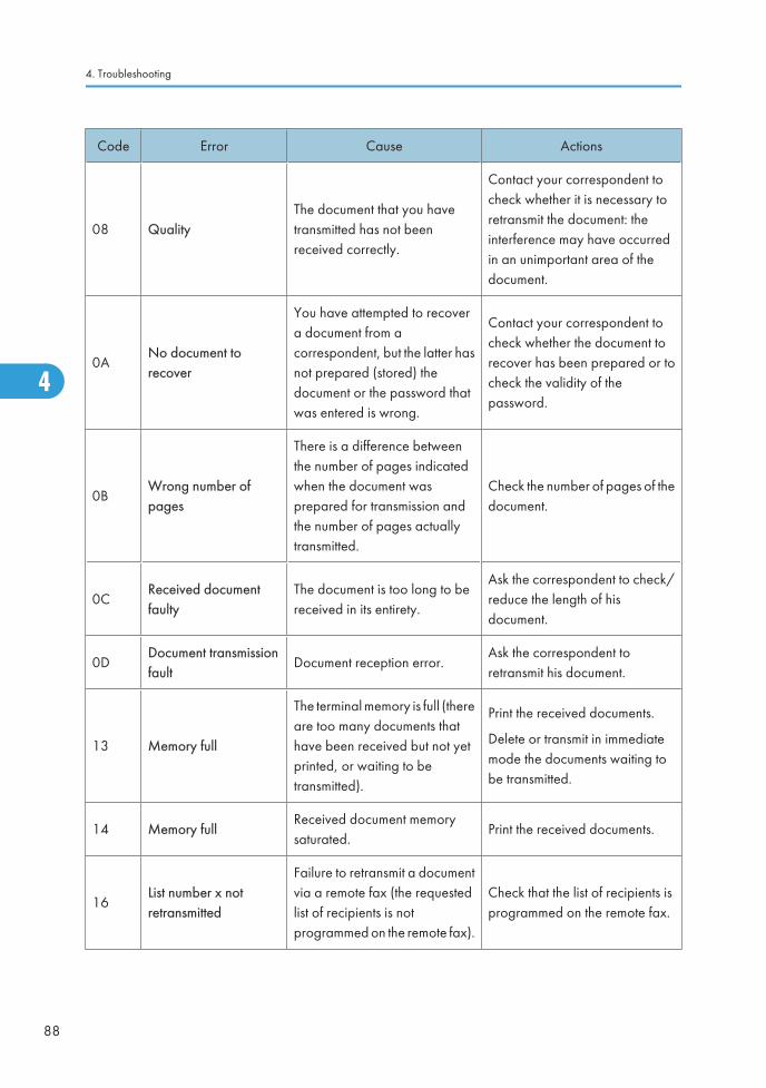
Code Error Cause Actions
08 QualityThe document that you havetransmitted has not beenreceived correctly.
Contact your correspondent tocheck whether it is necessary toretransmit the document: theinterference may have occurredin an unimportant area of thedocument.
0ANo document torecover
You have attempted to recovera document from acorrespondent, but the latter hasnot prepared (stored) thedocument or the password thatwas entered is wrong.
Contact your correspondent tocheck whether the document torecover has been prepared or tocheck the validity of thepassword.
0BWrong number ofpages
There is a difference betweenthe number of pages indicatedwhen the document wasprepared for transmission andthe number of pages actuallytransmitted.
Check the number of pages of thedocument.
0CReceived documentfaulty
The document is too long to bereceived in its entirety.
Ask the correspondent to check/reduce the length of hisdocument.
0DDocument transmissionfault
Document reception error.Ask the correspondent toretransmit his document.
13 Memory full
The terminal memory is full (thereare too many documents thathave been received but not yetprinted, or waiting to betransmitted).
Print the received documents.
Delete or transmit in immediatemode the documents waiting tobe transmitted.
14 Memory fullReceived document memorysaturated.
Print the received documents.
16List number x notretransmitted
Failure to retransmit a documentvia a remote fax (the requestedlist of recipients is notprogrammed on the remote fax).
Check that the list of recipients isprogrammed on the remote fax.
4. Troubleshooting
88
4

Code Error Cause Actions
19Stopped bycorrespondent
Communication stopped byyour correspondent (Example: afax attempts to recover adocument from your fax, whilethere is no document waiting forthis correspondent).
1A DisconnectTransmission has not started (thephone line is too noisy).
Check the quality of the phoneline or restart the transmission ata later time.
1BDocument transmissionfault
Document transmission error.
Transmission: restart thetransmission.
Reception: ask yourcorrespondent to retransmit thedocument.
Error Code
89
4

4. Troubleshooting
90
4

5. Service Tables
User ModeRefer to the Operating Instructions.
91
5

Tech Mode
How to go into Tech Mode
Each one of the administrator functions described here can be accessed via a specific succession of keys.
The alphabetic keys are available via the navigation keys and via the keyboard.
For example, to enter a sequence > "Q" > "A" (launching scanner tuning):
1. Press the following key .
2. Press the following key Q.
3. Press to display all the options available until you reach "A".
Confirm your choice with "OK".
Installation Parameters
The installation parameters are used for adapting the machine to the specific requirements of users incountries where it is to be installed.
Each machine is programmed with the factory test configurations. The installer can obtain a printed copyof these parameters (sequence of keys > "5" > "4").
Remark(s): It is recommended to conserve a paper copy of the list of parameters provided at delivery.
Access to these parameters is only authorized for the maintenance and/or installation service technicians.
The machine comes with software blocks called SOS (Soft Switches) No. 1 to 60. Each block is made upof 8 bits called bit 1 to 8. Each bit has a value of 0 or 1. Reading the block (from bit 1 to bit 8) on thedisplay panel is done from right to left. The blinking cursor is always located on the bit 8 (on the extremeleft) when selecting the configuration.
Access to the configuration bytes is available via the initialization screen, via a succession of keys: >"Q" > "#"
The significance of the principal configuration parameters for the machine is provided as following section"List of Configurations". They can be modified just like any other parameter.
List of Configurations (SOS)
Remark(s): The undocumented Soft Switches in this section are reserved.
5. Service Tables
92
5
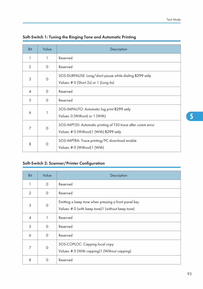
Soft-Switch 1: Tuning the Ringing Tone and Automatic Printing
Bit Value Description
1 1 Reserved
2 0 Reserved
3 0SOS-DURPAUSE: Long/short pause while dialing B299 only
Values: # 0 (Short 2s) or 1 (Long 6s)
4 0 Reserved
5 0 Reserved
6 1SOS-IMPAUTO: Automatic log print B299 only
Values: 0 (Without) or 1 (With)
7 0SOS-IMPT30: Automatic printing of T30 trace after comm error
Values: # 0 (Without)1 (With) B299 only
8 0SOS-IMPTRA: Trace printing/PC download enable
Values: # 0 (Without)1 (With)
Soft-Switch 2: Scanner/Printer Configuration
Bit Value Description
1 0 Reserved
2 0 Reserved
3 0Emitting a beep tone when pressing a front panel key
Values: # 0 (with beep tone)1 (without beep tone)
4 1 Reserved
5 0 Reserved
6 0 Reserved
7 0SOS-COPLOC: Capping local copy
Values: # 0 (With capping)1 (Without capping)
8 0 Reserved
Tech Mode
93
5

Soft-Switch 3 : Line Configuration B299 only
Bit Value Description
1 1 SOS-NIVEMI: Transmission level
Values: 00 = 0 dBm
01 = -1 dBm
...
# 06 = -6 dBm
...
0F = -15 dBm
2 0
3 0
4 1
5 0 Reserved
6 0SOS-SEUILREC: Reception threshold 1
Values: # 0 (-43 dB) 1 (-47 dB)
7 0SOS - EPTV29: Use Echo Protect Tone with V29
Values: #0 (Without) 1 (With)
8 0SOS - ECHO: Echo canceling
Values: #0 (Without) 1 (With)
Soft-Switch 4: Fax Protocol Configuration
Bit Value Description
1 1SOS-MODPRIV: Communication in private mode B299 only
Values: 0 (Without)# 1 (With)
2 0SOS-DIS-COURT: Restricted DIS size B299 only
Values: # 0 (long DIS (complete)) 1 (Short DIS)
3 0
SOS-TCF: TCF accept criterion B299 only
Values: # 0 (Normal): refused if there has not been 1 continuous second.
1 (Special): 1 discontinuous second in the TCF, then accepted systematically at2 400 b/s.
4 0 SOS-RTN: Page accept criterion B299 only
Values: # 0 (10 percent)5 0
5. Service Tables
94
5

Bit Value Description
1 (15 percent)
2 (20 percent)
3 (no check)
6 1SOS-DISINF: Unlimited DIS length B299 only
Values: 0 (Without)# 1 (With)
7 0SOS-LGINF: Maximum length of scan, printing, communication
Values: # 0 (1 meter) 1 (3 meters)
8 1SOS-ECM: Restricted ECM B299 only
Values: 0 (Without) # 1 (With)
Soft-Switch 5: Voice/Loudspeaker Configuration B299 only
Bit Value Description
1 1 Reserved
2 0 Reserved
3 0 Reserved
4 0 Reserved
5 0 Reserved
6 1SOS-HP: Line monitoring during fax comm.
Values: # 0 (Without) 1 (With)
7 1 Reserved
8 0 Reserved
Soft-Switch 6: Line Adjustment B299 only
Bit Value Description
1 0 Reserved
2 0 Reserved
Tech Mode
95
5

Bit Value Description
3 0 Reserved
4 0 Reserved
5 0 Reserved
6 0 Reserved
7 0 Reserved
8 0SOS-TSTDCOM: Driver test functions
Values: # 0 (Without)1 (With)
Soft-Switch 9: Approval + Communication Applications B299 only
Bit Value Description
1 0 Reserved
2 0 Reserved
3 0 Reserved
4 1SOS-REPERR: Redialing from page fault
Values: 0 (Without) # 1 (With)
5 1SOS-NOTREMIS: Printing of first page on transmission rapport
Values: 0 (Without) # 1 (With)
6 0SOS-GRILLAGE: Burn phone numbers
Values: #0 (Without) 1 (With)
7 1
SOS-LIGNE5S: Lines of 5 seconds during reception
Values: 0 (Length of lines not limited to 5 sec./line)
# 1 (Maximum length of a line: 5 seconds)
8 1SOS-AGRE-FRA: Fench approval functions
Values: 0 (Without) # 1 (With)
5. Service Tables
96
5

Soft-Switch 10: Communications: Locks/Miscellaneous B299 only
Bit Value Description
1 0
SOS-AFFVIT: Communication rate display
Values: # 0 (Without) the page number is displayed.
1 (With) the comm. rate is displayed.
2 1SOS-BTYPNUM: Access to impulse/DTMF parameter
Values: 0 (With) Reserved # 1 (Without)
3 0 Reserved
4 1 Reserved
5 1
SOS-TLRFAX: Remote readout by fax (ATTENTION!!!)
Values: # 0 (Remote readout to Quadrige in transparent mode)
1 (Remote readout by fax)
6 0 Reserved
7 0SOS-SONREA: Access to redialing parameters (screen /printer)
Values: # 0 (No access)1 (With access)
8 0 Reserved
Soft-Switch 18: Coding/ UART Rate B299 only
Bit Value Description
1 1 SOS-CODMEM: Stored document encoding type
Values: 00 (RL Coding)
01 (MH Coding)
10 (MR Coding)
#11 (MMR Coding)
2 1
3 1 SOS-CODCOM: COM negotiated encoding type
Values: 01 (MH Coding)
10 (MR Coding)
#11 (MMR Coding)
4 1
Tech Mode
97
5

Bit Value Description
5 0 Reserved
6 0 Reserved
7 0SOS-AFF_VIT_REELLE : Show/hide real communication rates
Values: # 0 (show reduced rates) 1 (show real rates)
8 0 Reserved
Soft-Switch 19: Miscellaneous Software Functions B299 only
Bit Value Description
1 0 Reserved
2 1 Reserved
3 0SOS-GROUPE: Restriction on groups (or distribution list)
Values: # 0 (No groups) 1 (Groups accepted)
4 0SOS-REGULREC: T30 reception control inhibited
Values: # 0 (Without) 1 (With)
5 0 Reserved
6 1SOS-MENUCLAVIER: Hide keyboard menus and force QWERTY keyboard
Values: 0 (Show) # 1 (Hide)
7 0SOS-ONETOUCH: Enable "One touch" functions
Values: # 0 (Without) 1 (With)
8 0SOS-TLC: Accept software download via STN
Values: # 0 (Without) 1 (With)
Soft-Switch 21: T4 Decoder/ Debug
Bit Value Description
1 1SOS-TRAITLIGERR: T4 decoding line copying mode
B299 only
5. Service Tables
98
5

Bit Value Description
Values: 0 (For each line with an error) # 1 (Only once, then destroy)
2 0 Reserved
3 0 Reserved
4 0 Reserved
5 1
SOS-GARBAGE-FLASH: Flash memory garbage collection method
Values: 0 (garbage collection when application terminates)
# 1 (garbage collection as background task)
• Taken into account only after reboot of the CPU
6 0 Reserved
7 0
SOS-DETECT OCCUP: Inhibition of engaged tone detect
B299 only
Values: # 0 (Without)1 (With)
8 0 Reserved
Soft-Switch 22: Miscellaneous B299 only
Bit Value Description
1 1 SOS-DUREE-2100: Transmission time of the 2100 modified for V34 reception
Values: 00 (5 seconds)
01 (4.5 seconds)
10 (4 seconds)
# 11 (3.5 seconds)
2 1
3 0SOS-SORTIMP: Printing at the end of fax communications
Values: # 0 (Printing during comm.) 1 (Print after comm.)
4 0 Reserved
5 0 Reserved
6 0 Reserved
Tech Mode
99
5

Bit Value Description
7 0 Reserved
8 0 Reserved
Soft-Switch 23: Miscellaneous
Bit Value Description
1 1
SOS-JBIG: SUPER 3 capability to execute communication with JBIG encoding.B299 only
Values: 0 (No SUPER G3) 1 (Negotiated SUPER G3)
2 1 Reserved
3 0
SOS-FSI-NOCOVER: Inhibition of generation of cover pages.
B299 only
Values: # 0 (FSI V6 cover page) 1 (FSI V7 cover page)
Ricoh model can not set.
4 1
SOS-COMPACTE-RL: Compacting of run length (for fax server ELLIPSE) B299only
Values: 0 (No compacting) # 1 (Compacting run length of no length)
5 0
SOS-DEBRIDAGE-JAUGE: Acceptation of EEPROM cards at any moment.
Values: # 0 (No) 1 (Yes)
Return to 0 after removing the card.
6 0 Reserved
7 0 Reserved
8 1 Reserved
Soft-Switch 26: Miscellaneous B299 only
Bit Value Description
1 0 Reserved
2 0 Reserved
5. Service Tables
100
5

Bit Value Description
3 0 Reserved
4 0Restriction on USB function
Values: # 0 (Without)1 (With)
5 0
With or without duplication of on page passage threshold.
Values: #0 : No duplication: NBI_SUP_B (1cm)
1 : Duplication: NBI_SUP_B * 2 (2 cm)
6 0
RR/RNR regulation limitation to 4 in T30.
Values: #0 : No limitation
1 : With limitation
7 1
Double alternation optocoupler use
Values : 0: Optocoupleur mono alternation
#1 : Optocoupleur double alternation
8 0 Reserved
Soft-Switch 27: Miscellaneous B299 only
Bit Value Description
1 0
Size of remote readout serial number
#1000: 8 digits remote readout serial number
1111: 15 digits remote readout serial number (only for EGT for now)
2 0
3 0
4 1
5 0 Waiting time before validation of unexpected modulation in comparison withexpected modulation. (~/driver/m_lucent/sms_m_dp2v/src/dpmain.c)
# 00 = 60 + 0*30 ms= 60 ms
01 = 60 + 1*30 ms = 90 ms
02 = 60 + 2*30 ms = 120 ms
03 = 60 + 3*30 ms = 150 ms
04 = 60 + 4*30 ms = 180 ms
05 = 60 + 5*30 ms = 210 ms
6 0
7 0
8 0
Tech Mode
101
5

Bit Value Description
06 = 60 + 6*30 ms = 240 ms
......
0F = 60 + 15*30 ms = 510 ms
Soft-Switch 29: Miscellaneous B299 only
Bit Value Description
1 0 Reserved
2 0 Reserved
3 0 Reserved
4 0
Force the V29 modulation for 9600 and 7200 rates
#0 : Enabled
1: Disabled
5 0 Reserved
6 0 Reserved
7 0 Reserved
8 0 Reserved
Soft-Switch 31: Miscellaneous B299 only
Bit Value Description
1 0 Reserved
2 0 Reserved
3 0 Reserved
4 0Displaying the TRASH CAN consumable (in the 86 menu)
Values: # 0 (Without) 1 (With)
5 0Using the DHCP queries in ad-hoc WLAN mode
Values: # 0 (With) 1 (Without DHCP-directly APIPA)
5. Service Tables
102
5

Bit Value Description
6 0 Reserved
7 0 Reserved
8 0 Reserved
Soft-Switch 32: Miscellaneous
Bit Value Description
1 0 Reserved
2 0 Reserved
3 0 Reserved
4 0 Reserved
5 1 Using One Touch Management for Ricoh values: 0 (without) #1 (with) B299 only
6 1Using Ricoh Toner Management
Values: 0 (Without) #1 (With)
7 0 Reserved
8 1 Reserved
Soft-Switch 33: Miscellaneous B299 only
Bit Value Description
1 0 Reserved
2 0 Reserved
3 0 Reserved
4 0 Reserved
5 1Question to the user about a good fax printing values : 0 (with) #1 (withoutquestion to user)
6 0 Reserved
Tech Mode
103
5

Bit Value Description
7 0 Reserved
8 0 Reserved
Administrator Functions
Initializing and erasing memory
Before you start, set the “Soft-Switch 1” bit 8 parameter value to1.
Description Input Keys
Reset all parameters (user, installer or technical) to the defaultconfiguration (factory configuration):
> "#" > "0"
Erase the directory: B299 only > "#" > "1"
Erase the logs : B299 only > "#" > "2"
Erase the printer counters: > "#" > "3"
Erase the consumable counters (, "8", "5"):
• To see the initialization message (this requires inserting the smartcard INIT), switch On then Off.
Open the front door then: >"#" > "4"
Reinitialize the flash data (erases all):Open the front door then: >"#" > "5"
Reset to default configuration (combination of functions 0 and 8): > "#" > "7"
Erase all documents stored in memory: > "#" > "8"
Erase the first element of the printer queue : > "#" > "I"
Erase Printer Error: > "#" > "T"
Switch ON/OFF the machine after changing settings.
5. Service Tables
104
5

Other Functions
Description Input Keys
Printing all parameters (including installation and technicalparameters):
> "Q" > "1"
Switching to forced standby mode regardless of the clock: > "Q " > "2"
Switching to software download via a phone line:
B299 only > "Q" > "3"
Switching to software download via a computer link: > "Q" > "4"
Save the directory and parameters on I2C card:
B299 only > "Q" > "5"
Save the directory and parameters via STN:
B299 only > "Q" > "7"
Accept directory and parameters download via STN:
B299 only > "Q" > "8"
Restore the directory and parameters from I2C card:
B299 only > "Q" > "9"
Launching scanner tuning: > "Q" > "A"
Displaying miniboot version: > "Q" > "B"
Displaying the state of the applications, traffic and drivers: > "Q" > "E"
Display modem software version: B299 only > "Q" > "M"
Entering the serial number (with the SOS 1 bit 8 at 1): > "Q" > "N"
Displaying the internal counters: > "Q" > "O"
Displaying the GDI throughput: B299 only > "Q" > "P"
Rebooting the machine manually (with the SOS 1 bit 8 at 1): > "Q" > "R"
Displaying main software version, checksum: > "Q" > "V"
Displaying the printer firmware version: > "Q" > "W"
Printing internal counters: > "Q" > "Y"
Tech Mode
105
5

Description Input Keys
Tuning the level of PDL symbols: > "Q" > "Z"
Replacing the CPU Board
To replace the machine’s CPU board, follow this procedure:
1. Print the machine’s parameters (user, administrator and technical) and the activity counter values inorder to keep a record ( > "5" > "4").
2. Replace the CPU board (* "CPU Board" in the Chapter "Replacement and Adjustment").
3. Tune the scanner ( > "8" > "0").
Replacing the Scanner
To replace the scanner, follow this procedure:
1. Print the machine’s parameters (user, administrator and technical) and the activity counter values inorder to keep a record ( > "5" > "4").
2. Replace the scanner (* "Flatbed Scanner Assembly" in the Chapter "Replacement and Adjustment").
3. Tune the scanner ( > "8" > "0") only if the quality of the copy is unsatisfactory.
New Cartridge
Three toner cartridge replacement procedures can be used depending on the TONER MANAGEMENTsetting.
• TONER MANAGEMENT setting set to WITH [0-10%]: the replacement of the cartridge can beperformed only when the message Toner near end is displayed. At the end of replacement, validationwith the smart card is required.
• TONER MANAGEMENT setting set to WITH [0-100%]: the replacement of the cartridge can beperformed at any time. At the end of replacement, validation with the smart card is required.
• TONER MANAGEMENT setting set to WITHOUT: the replacement of the cartridge can be performedat any time and no validation with the smart card is necessary. When set to WITHOUT, the screendisplays TONER ? %.
To set the TONER MANAGEMENT setting, select 2979 - SETUP / TECHNICALS / TONERMANAGEMENT and choose the setting.
Replacement Procedure
• This procedure applies when the setting TONER MANAGEMENT is set to WITH [0-10%].
5. Service Tables
106
5

• When set to With [0-100%], follow the procedure from step 2.
• When set to WITHOUT, follow the procedure from step 2 to step 7.
Your machine comes with a current consumable management system. It tells you if your toner cartridge isclose to its end of cycle. The message "TONER NEAR END" will appear on your machine screen.
To quit this screen, press "OK" key.
To replace the toner cartridge, proceed as shown below.
1. When the message "TONER EMPTY REPLACE <OK>" is displayed on the screen, press "OK" key.
2. The message "OPEN FRONT COVER REPLACE TONER" is displayed on the screen.
3. Stand in front of the device.
4. Push on the left and right sides of the cover and pull it towards you.
5. Raise and remove the toner cartridge from the machine.
6. Unpack the new cartridge and insert it into the slot as indicated in the diagram below.
7. Close the cover.
The following message appears:
8. Press "OK" key.
9. When the message "HAVE YOU CHANGED THE TONER? <OK>" appears, insert the toner cardprovided with the new toner cartridge as shown on the picture below.
Tech Mode
107
5

10. The message "PLEASE WAIT" appears.
11. The message "NEW TONER REMOVE CARD" appears after the smart card has been read.
12. Remove the smart card from the reader, the machine is ready to print again.
• To continue the printing of your documents when the message "TONER NEAR END" is displayed, setthe TONER MANAGEMENT setting to WITHOUT.
• However, this procedure is not recommended as disabling toner
• management (parameter set to WITHOUT) can lead to fax loss and
• toner being spilled in your print mechanism.
Issues with smart cards
If you use a smart card that has already been used, the machine will display "PLEASE WAIT", then "REMOVECARD ALREADY USED".
If you use a defective smart card, the machine will display "PLEASE WAIT", then "UNKNOWN CARDREMOVE CARD".
If the C button is pressed while the smart card is being read, the machine displays "ACTION CANCELLEDREMOVE CARD"
5. Service Tables
108
5

Firmware DownloadUpdating the machine's software is principally carried out via a PC connection (USB only).
The principal software which controls the card core and the miniboot software may be downloadedseparately.
• After downloading the principal software, the scanner may require tuning.
• Enter > "8" > "0" and confirm by pressing "OK". Wait until the screen refreshes and reverts to thedefault screen mode. Make a local copy to check its quality.
Via PC Connection
Via the executable TELUSB2
This procedure requires a standard PC running under Windows and equipped with the TELUSB2.exe(version 2.2.0.0) executable and a USB cable.
Before you start, position the bit No. 8 to 1 on the Soft-switch 1.
1. Connect the machine to a PC with the USB cable.
2. Set the machine to download via PC mode ( > "Q" > "4").
3. Launch the executable TELUSB2.EXE and select the file to be downloaded (extensions .bin or .fwf).
After about ten seconds, a window will appear to indicate that the download was successful. Themachine should not be restarted immediately.
If the machine restarts immediately, the file is corrupted (checksum false) or the software is notcompatible with the machine. The machine then restarts with the initially installed software. In this case,check the file and repeat step 1.
4. After about 40 seconds, the machine switches off then restarts. The message "WAIT" is displayed.
5. Check the version of the principal software and checksum by typing in > "Q" > "V" or check thesoftware version and the miniboot’s checksum by typing in > "Q" > "B".
Via the UDPATEDEVICE function of COMPANION SUITE
This procedure requires a standard PC running under Windows equipped with the Companion Suitesoftware and a USB cable.
Before you start, check that the machine is connected to the PC via the USB cable.
1. On the PC, click "START" > "COMPANION SUITE" > "COMPANION" > "UPDATE".
Firmware Download
109
5

2. In the window "MFUPDATEPRINTER", click on the "BROWSE" icon and select the update file to bedownloaded on the machine.
3. After selecting the update file, click on "OPEN".
4. Click on "UPDATE".
Downloading with the Miniboot
Via the executable TELUSB2
This procedure requires a standard PC running under Windows and equipped with the TELUSB2.exe(version 2.2.0.0) executable and a USB cable.
Before you start, position the bit No. 8 to 1 on the Soft-switch 1.
1. Set the machine’s On/Off switch to Off (position 0).
2. Connect the machine to the PC via the USB cable.
3. Press the "4", "6" and "0" keys simultaneously and set the On/Off switch to On (position I).
The machine is switched on. The message "USB DETECTED WAITING FOR DOWNLOAD" isdisplayed and an alert sound is emitted. If the message WAITING FOR A USB LINK is displayed,check that the machine is properly connected to the PC via the USB cable.
4. Release the "4", "6" and "0" keys.
5. Continue downloading from step 3 of "Via the executable TELUSB2" in the section "Via PCConnection".
Via the UDPATEDEVICE function of the COMPANION SUITE
This procedure requires a standard PC running under Windows and equipped with the Companion Suitesoftware and a USB cable.
Before you start, position the bit No. 8 to 1 on the Soft-switch 1.
1. Set the machine’s On/Off switch to Off (position 0).
2. Connect the machine to the PC via the USB cable.
3. Press the "4", "6" and "2" keys simultaneously and set the On/Off switch to On (position I).
4. The machine is switched on. The message "RECEIVING FILE" is displayed and an alert sound is emitted.
5. Release the "4", "6" and "2" keys.
6. Continue downloading from step 1 of the "Via the UDPATEDEVICE function of COMPANION SUITE"in the section "Via PC Connection".
5. Service Tables
110
5

Reminders
• Every fax is equipped with a copy counter, implemented in EEPROM memory on the CPU board. Thiscounter is used in particular by the Remote Readout function. It can be consulted by the user. Thiscounter cannot be modified. It is stored indefinitely.
• Before any corrective intervention on the machine that risks modifying the installation parameters orthe value of the counter (replacement of the CPU board or installation of new software), a manualRemote Readout transmission should be performed, if the state of the machine allows it. If thistransmission is not possible for any reason, print out the Remote Readout parameters or display thecopy counter and note these values on the intervention report.
Firmware Download
111
5

Storing User ParametersThe condition of the printer consumable (toner cartridge) is stored in EEPROM memory (on the CPU card)and can be read via the command > "8" > "6".
This evaluation, provided in percentage format, indicates the remaining quantity of toner in relation to theconsumable’s initial values.
The printer activity counters are also stored in flash (on the CPU card), they can be read via the command > "8" > "2" and can be printed via > "5" > "4" (printing of parameters).
These absolute counters reflect the machine’s overall utilization regardless of the consumable:
• Number of pages sent ;
• Number of pages received ;
• Number of pages printed ;
• Number of pages scanned.
• ANY MAJOR OPERATION ON THE MACHINE (REPLACEMENT OF THE CPU CARD, MAJORUPGRADE OF THE MACHINE’S SOFTWARE) MAY LEAD TO THE PERMANENT LOSS OF THEUSER PARAMETERS AND THE ACTIVITY COUNTER VALUES.
• IF SUCH OPERATIONS ARE NECESSARY, PRINT THE PARAMETERS AND COUNTERS ( > "5" >"4") TO RETAIN A COPY.
5. Service Tables
112
5

6. Detailed Descriptions
Component Layout
Mechanical Components
No. Name Description
A Laser UnitConsists of the laser diode unit, cylindrical lens, F-theta lens,polygon mirror motor, and other laser optical components.
B Toner CassetteConsists of the OPC drum, toner, toner application roller,development roller, charge brush roller, cleaning blade, andother development components.
C Upper Tray Bottom PlatePresses paper stacked in the upper paper tray against thepaper feed roller.
D Paper Feed RollerPicks up the top sheet of paper from the stack in the upper papertray and feeds it into the transfer area.
113
6

No. Name Description
E Transfer RollerApplies a charge to the paper to pull the toner off the drumand onto the copy paper.
F Pressure Roller Applies pressure to the paper during fusing.
G Hot Roller Fuses the toner to the copy paper.
H Paper Exit Roller Feeds the paper out of the printer.
6. Detailed Descriptions
114
6

Printing
Printing Processes around the Drum
This machine uses a negative toner system.
Charge: The charge brush roller [A] gives the OPC drum [B] surface a negative charge.
Exposure: A laser [C] writes a latent image on the drum. The charge in the area exposed by the laser beamdrops.
Development: The development roller [D] carries toner to the drum and develops the latent image on thedrum. The following charges are applied.
Development bias (during printing): Toner application roller [E], Development roller [D]
Switching bias (At the start and the end of any print process): Toner application roller [E], Developmentroller [D]
Image Transfer: The transfer roller [F] pulls the toner from the drum onto the paper [G].
Paper Separation: The antistatic brush [H] removes the charge on the underside of the paper to help thepaper separate from the drum.
Printing
115
6

Drum Cleaning: The cleaning blade [I] removes any toner remaining on the drum after the image istransferred to paper.
High voltages [J] are supplied from the Power Supply Unit board.
Charge
The OPC (Organic Photoconductor) drum [A] used in this machine is small in diameter. This allows a verycompact design.
A charge roller [B] charges the photoconductor. The charge roller has the advantage of not generatingozone. A large negative voltage is applied from the Power Supply Unit board to the charge roller. Thischarge roller gives the OPC drum surface a negative charge.
6. Detailed Descriptions
116
6

Laser Exposure
Overview
Laser Unit Layout
A : Laser Diode Unit F : Laser Synchronization Detector
B : Polygon Mirror Motor G : Cylindrical Lens
C : F-theta Lens H : Synchronization Detector Lens
D : First Mirror I : Shutter
E : Second Mirror
This machine uses a laser diode to produce an electrostatic latent image on the OPC drum. The laser diodeunit converts image data into laser pulses, and the optical components direct these pulses to the OPC drum.
As a mechanical safety feature, the shutter [I] closes to block the laser beam path whenever the front dooris opened.
Printing
117
6

Block Diagram
The Engine Board controls the laser diode power (APCSH) and transfers data for printing to the laser diode(VIDEO). As an electrical safety feature, there is an interlock switch on the Engine Board. This switch cutspower whenever the front door is opened.
Error Conditions
Laser Error
The machine detects laser synchronization signal pulses (PGSYCI) 70 milliseconds after the (LDENA) signalis sent. It detects a laser error if the pulse count does not reach the specified number within 400 milliseconds.
When this occurs, the machine warns the customer on the LCD panel (Error 56).
Polygon Mirror Motor Error
The machine detects a polygon mirror motor error when the (PMLOK) signal does not go low within 3.5seconds of the (PMENA) signal. When this occurs, the machine warns the customer on the LCD panel (Error57).
6. Detailed Descriptions
118
6

Development
Overview
This machine uses mono-component toner, which is composed of resin and ferrite. The toner mixing bar[A] stirs and carries toner to the toner application roller [B]. The toner application roller supplies toner tothe development roller [C]. As the development roller turns past the toner metering blade [D], only a thincoating of negatively charged toner particles stays adhered to the development roller.
During printing, a bias voltage is applied to the toner application roller and another bias voltage is appliedto the development roller. The toner is transferred from the toner application roller to the development rollerby the potential difference between these two rollers.
The development roller applies toner to the exposed areas of the latent image as they turn past the drum.
Printing
119
6

The voltage applied to the development roller and the toner application roller is supplied through terminals([A] for the development roller and [B] for the toner application roller) from the Power Supply Unit board.
Toner End Detection
This machine does not have toner end detection.
Transfer and Separation
Overview
6. Detailed Descriptions
120
6

This machine uses a transfer roller [A], which touches the OPC drum [B] surface. A constant current isapplied to the transfer roller from the power supply unit board [C]. The positively-biased transfer roller pullsnegatively-charged toner off the drum. The curvature of the drum, and the antistatic brush [D], help thepaper [E] to separate from the drum.
Cleaning Mode
If a paper jam occurs during printing, toner may be transferred to the transfer roller surface. To preventtoner from transferring to the underside of the paper, the transfer roller must be cleaned before the nextprint job.
While the machine is in the cleaning mode, the Power Supply Unit board applies a negative voltage to thetransfer roller. The negatively charged toner on the transfer roller is then transferred back to the drum.
The machine goes through the cleaning mode at the following times.
• At power-up: The process starts when the fusing temperature reaches the standby temperature.
• When the cover is opened and then closed during the printing process.
• After a printer jam has been cleared.
Drum Cleaning
The cleaning blade and the used toner tank are contained in the toner cartridge.
A counter blade system is used for drum cleaning. The cleaning blade [A] removes any toner remainingon the drum after the image is transferred to the paper. This removed toner is stored in the used toner tank[B].
There is no used toner overflow detection mechanism, because the used toner tank is large enough for thelifetime of the toner cassette.
Printing
121
6

Paper Feed and Registration
Overview
Paper Feed System: Feed roller [A] and Friction pad [B]
Paper Lift Mechanism: Bottom plate with spring [C]
Sheet feeder 1 sheet feeder [D]
Tray Capacity: 250 sheets [E]
Paper End Detection: Paper end sensor
Paper Size Detection: None
6. Detailed Descriptions
122
6

Paper Feed Drive Mechanism
The feed roller [A] is located above the upper tray bottom plate [B] and the friction pad [C]. It allows onlyone sheet to feed from the paper tray. They are controlled by the paper feed clutch [D]. The registrationsensor detects the leading edge of the paper and synchronizes paper feed with the activation of the laserdiode to write the image on the OPC drum.
Paper Feed Operation
A : Paper feed drive gear D : Friction pad
B : Paper feed clutch E : Paper feed sensor
Printing
123
6

C : Paper feed roller F : Registration sensor
The paper feed drive gear [A] always rotates while the main motor rotates, since the paper feed clutch(magnet clutch) [B] is energized to turn the paper feed roller [C].
When the paper feed clutch [B] is energized to turn the feed roller, the paper feed roller feeds one sheetof paper from the tray. The paper is fed into the machine by the registration roller.
Registration
The registration sensor [A] detects the leading edge of the paper and synchronizes paper feed with thewriting of the image on the drum, so that the image and paper match up properly. This sensor also detectspaper feed jams.
6. Detailed Descriptions
124
6

Paper End Detection
This machine has the paper end sensor [A] built into it. The paper end sensor detects the presence orabsence of paper. The sensor has an actuator [B] that extends through a slot in the paper tray bottom plate[C], and the sensor is actuated when paper is placed in the upper tray.
When the upper tray runs out of paper, the actuator of the paper end sensor moves into the slot in the uppertray bottom plate. This informs the CPU that paper has run out.
Jam Detection
Jam 1. Paper jam at the paper cassette
When the registration sensor does not turn on within 2.65 seconds after the paper pick-up clutch for thepaper cassette turns on.
Jam 2. Paper did not pass the registration sensor
When the registration sensor does not turn off within the specified time for passing each paper size (seebelow) + 3 seconds after the registration sensor turns on.
Paper Size A4SEF A5SEF A5LEF A6SEF
Specified Time(msec)
2830 2000 1410 1410
Printing
125
6

Paper Size B5SEF B6SEF Letter SEF Legal SEFEnvelope
(91x191mm)
Specified Time(msec)
2450 1740 2660 3400 1820
Jam 3. Paper did not reach the fusing unit
When the paper exit sensor does not turn on within 2.1 seconds after the registration sensor turns on.
Jam 4. Paper jam in the fusing exit area
When the paper exit sensor does not turn off within 3.0 seconds after the registration sensor turns off.
Jam 5. Paper no feed jam in the bypass tray
When the registration sensor does not turn on within 1.6 seconds after the main motor starts.
Fusing
Overview
6. Detailed Descriptions
126
6

After the image is transferred, the paper enters the fusing unit. The image is fused to the paper by applyingheat and pressure through the use of a hot roller [A] and pressure roller [B].
The CPU monitors the hot roller temperature through a thermistor [C] that is in contact with the hot rollersurface. A thermostat [D] protects the fusing unit from overheating.
The hot roller strippers [E] separate the copy paper from the hot roller and direct it to the exit rollers [F].The paper feed/exit sensor [G], which is under the fusing unit, monitors the progress of the copy paperthrough the fusing unit and detects misfeeds. The exit rollers [F] drive the copy paper to the paper outputtray.
Springs [H] at the front and rear apply the proper fusing pressure between the hot roller and pressure roller.
The fusing lamp [I] is located in the hot roller.
Power Control
When the main switch is turned on, the machine turns on the fusing lamp. For printing, the machine raisesthe fusing temperature to 170°C. The fusing temperature is kept at 170°C during printing. For stand bymode the machine goes down the fusing temperature to 80°C.
Cover Switch
When the front door is opened, the interlock switch [A] will be opened and power supply to the followingparts gets cut.
• Power pack
• Laser diode driver
• Fan motor
Printing
127
6

• Main motor
• Polygon mirror motor
• Fusing lamp
Paper Feed Drive Release and Fusing Drive Release
The main motor drives the paper feed unit, the transfer roller, the toner cassette, and fusing unit through aseries of gears as follows.
Main motor [A]
↓
Idle gear 1[B]
Hot roller gear [H]
↓
Idle gear 4 [I]
↓
Exit roller gear [J]
↓
Idle gear 2 [C]
↓
OPC drum gear [F]
↓
Transfer roller gear [G]
↓
Idle gear 3 [D]
↓
Paper feed
drive gear [E]
6. Detailed Descriptions
128
6

7. Specifications
General Features
Copier
B279 B299
Dimension (W x D x H) (mm) 447 x 344 x 386 447 x 386 x 412
Weight (basic machine) 11 kg 12 kg
Power Supply220 - 240V
50/60 Hz - 4.5 A
ElectricConsumption
Operating 340 W (Max. 900W)
Stand-by 13 W 16 W
Power Save 10 W 12 W
Noise EmissionOperating 51 dB (A) or less
Stand-by 29 dB (A) or less
Scan to mail
(drag and drop via Paper Port)TIFF-F, JPEG, PDF
Resolution of Scanner 600 x 600
Copier Speed 16 cpm
First Copy- Time
From ADF (B&W) - 13 sec. or less
From FB Scanner(B&W)
13 sec. or less 13 sec. or less
Zoom 25% - 400%
Paper Size ManagementA5, Legal,
Letter, A4
Multi-copy 1 - 99
Paper Capacity: Standard tray 250 (64g) /
129
7

200 (80g)
Copy-Tray Capacity 50
Paper WeightTray: 60 - 105 g/m2
By-pass: 52 - 160 g/m2
Energy saver mode Without / 5 / 15 / 30min / Standby period
USB host feature
No. / Position 1 / Front 2 / Front and back
Key to print Yes (JPEG,TIFF,TXT)
Scan to key Yes (TIFF)
Smart card feature
Directory & Parameter save cardNo Yes
Printer
B279 B299
Technology B/W Laser
Printing Speed 16 ppm
First Print Time 13 sec.
Printing Resolution 600 x 600 dpi
Printer Language GDI
Host Interface USB 2.0
Memory for printer 16 MB
Scanner
B279 B299
Type CIS Color Scanner
Color Depth 36 bits
Resolution Optical: 600 dpi
7. Specifications
130
7

Interpolated: 2400 dpi
B&W speed for A4
(excluding processing time)
600 X 200 dpi
600 X 300 dpi
600 X 600 dpi
3.9 seconds
3.9 seconds
10.5 seconds
Color speed for A4
(excluding processing time)
600 X 200 dpi
600 X 300 dpi
600 X 600 dpi
7.9 seconds
9.9 seconds
31.6 seconds
Gray Scale Level 256
Software Compatibility TWAIN
Maximum Paper Size A4, Letter
Fax (B299 only)
Type PSTN-Super G3
Coding scheme MH, MR, MMR, JBIG
Max speed 33600bps (V34Fax)
V34Fax capabilities 33600 to 2400 bps
V34Fax increments 2400 bps
V17 capabilities 14400, 12000, 9600, 7200 bps
V29 capabilities 9600, 7200 bps
V27ter capabilities 4800, 2400 bps
Automatic fall back Yes
Directory capacities 250
Transmission speed / ITU 2.5 seconds
General Features
131
7

ADF (B299 only)
Max. paper width and length 216 mm (W)/ 1000 mm (L)
Min. paper width and length 145 mm (W)/ 120 mm (L)
Paper weight 60 to 90 g/m2
Tray capacity 50 sheets
B&W speed (A4 excluding processingtime)
300 (200 for FAXa) x 100 dpi Less than 4.5 seconds
300 (200 for FAXa) x 200 dpi Less than 8 seconds
300 (200 for FAXa) x 300 dpi Less than 11.5 seconds
Color speed (for RP)
300 X 300 dpi Less than 11.5 seconds
7. Specifications
132
7

Supported Paper
Supports Paper traysADF
(B299 only)
Paper sizes Dimensions (mm) Main Manual Feeder
Legal 215.9 x 355.6 yes yes yes
A4 210 x 297 yes yes yes
Letter 215.9 x 279.4 yes yes yes
A5 148 x 210 yes yes yes
B5 (JIS) 182 x 257 no yes no
Executive 184.2 x 266.7 no yes no
A6 176 x 250 no yes no
Capacities 250 1 50
Supported Paper
133
7

7. Specifications
134
7

8. Apppendix
Block Diagram
Overview
135
8

Power Supply
The 24V and 5V power supply are provided by the printer.
Diagram of printer power supply connections:
Quartz
Diagram of CPU card clocks:
8. Apppendix
136
8

Reset
The reset is generated from 3.3V as all logical parts (DIGICOLOR2, memory, …) are supplied in 3.3V.
The reset is active during at least 100ms.
Printer’s reset diagram:
Block Diagram
137
8

P-to-P
Operation Panel Card
The operation panel card interfaces with the keyboard keys and the LCD display.
The LCD has its own driver in COB (Chip On Board).
The card also has an external connector to the smart card which is managed by the CPU.
List of connectors
Connector TopographyNumber of
pointsSex Position
CPU Connection P4200 16 Female Elbow top contact
LCD P4002 10 Female Elbow, top contact
Smart card P4001 10 Female -
CPU - P4200: CPU connection
Pin Signal Input/Output Utilization
1-7-8-10-15 GND - Ground
2 FERCAP I Detection of smart card
3 CVCC I/OSmart card power supply (3.3V)(controlled by I/O CVCC)
4 CLKPUCE O Smart card clock
8. Apppendix
138
8

Pin Signal Input/Output Utilization
5 RSTPUCE I Smart card reset
6 IOPUCE I/O Smart card data
9 SCLKPUP O Serial clock link for differential registers
11 RXPUP I Sending data from the operation panel
12 TXPUP O Sending data from the CPU
13 STROB1 -Out-of-register strobe to control thekeyboard
14 STROB2 -Out-of-register strobe to control thedisplay
16 P5V - 5V power supply
LCD - P4002: LCD interface
Pin Signal Input/Output Utilization
1 GND - Ground
2 V0 O Connected to V0
3 RS O Selection of registers
4 R/W ORead or Write (driver configured to writein OV)
5 LCD_E O Enable Signal (active at 1)
6 VCCLCD - Vcc: 4.5V to 5.5V
7 DB4 O Data (Bit 4)
8 DB5 O Data (Bit 5)
9 DB6 OI Data (Bit 6)
10 DB7 O Data (Bit 7)
P-to-P
139
8

Smart card - P4001: connection with the smart card
Pin Signal Input/Output Utilization
1 CVCC O Smart card power supply (3.3V)
2 RSTPUCE O Smart card reset
3 CLKPUCE O Smart card clock
4 - - Not connected
5 GND - Ground
6 - - Not connected
7 IOPUCE I/O Smart card data (input/output)
8 - - Not connected
S1 FERCAP I Smart card detection
S2 P5V - 5V power supply
CPU Card
The CPU card is based on the Digicolor2 circuit, which ensures the processor functions.
All the executable code is stored in the flash Z466.
This flash is divided into two zones: one zone is reserved for storing code and the other is reserved forstoring documents.
The code is loaded in SDRAM from this flash and the processor executes its instructions from the SDRAM.The SDRAM also serves as the operating memory for Digicolor2.
8. Apppendix
140
8

List of connectors
Connector TopographyNumber of
pointsSex Position
Printer CNx - - -
Speaker P1650 2 - -
Operation panel P4100 16 Female Straight, top contact
ADF scanner motor P4301 15 Female Straight
Flatbed scanner motor P4302 5 Female Straight
CIS P4380 12 Female Straight, top contact
Phone line P4420 4 Female -
External phone line P4440 4 Female -
USB Slave P4901 4External, type
USB type B-
USB Master P4950 4External, typeUSB type A
-
P-to-P
141
8

Connector TopographyNumber of
pointsSex Position
USB Master P4960 4External, typeUSB type A
-
CNx: printer connectors
Topography Connector Pin SignalInput/Output
Utilization
CN2 Diode laser
1 +5VLD -
2 XLDENA O Activating the laser
3 APCSH O Sampling
4 XDETP I Ray beam detector
5 GND - Ground
6 XVD O Diode laser video
7 NC - Not connected
CN3 Printer motor
1 P24VS - 24V power supply
2 GND - Ground
3 P5V - -
4 XMMENA - -
5 MMCLK - -
6 MMCW - -
7 XMMLOCK - -
8 MMGAIN - -
CN4 Fan
1 FANEMA OFan in operation motorsignal
2 GND - Ground
3 FANLOCK -
8. Apppendix
142
8

Topography Connector Pin SignalInput/Output
Utilization
CN5Paper outputclutch
1 +24VS - 24V power supply
2 XFPCL OElectric paper clutchsignal
CN6Paper detectioncaptors
1/4/7
GND - Ground
2 XFEED I Paper feed signal captor
3/6/9
+5V - 5V power supply
5 XREGIST I Register of signal captors
8 XMANUAL I Manual paper feed signal
CN7Paper outputcaptor
1 GND - Ground
2 XEXIT IFour paper output signalcaptors
3 +5V - 5V power supply
CN9 Debug
1 +5V - 5V power supply
2 DBGRXD I Debug receipt
3 DBGTXD O Debug command
4 GND - Ground
CN10 High voltage
1 TRAPWM0 OPWM signal for transfer ofcharger (+)
2 RAPWM1 OPWM signal for transfer ofcharger (-)
3 BIASPWM O PWM development signal
4 CHEPWM O PWM signal charger
5 XTRACTL O Charger signal
6 XBIASCTL O Development signal
P-to-P
143
8

Topography Connector Pin SignalInput/Output
Utilization
7 GND - Ground
8 +24VS - 24V power supply
CN11 Power supply
1 HTON O Phase Fuser control
2 ZEROC I Control signal
3 HTEN OFuser relay (Activated toH)
4 GND - Ground
5/12/13
+24V - 24V power supply
6/7/10/
11
GND - Ground
8/9 +5V - 5V power supply
CN12Temperaturecaptor
1 FTEMP IFuser temperaturedetector
2 GND - Ground
CN13Opening ofprinter covercaptor
1 P24V I 24V power supply
2 P24VS O 24V power supply
CN15IAO captor(presence oftoner)
1 XAIO I Detection of cartridge
2 GND - Ground
CN16Motortemperaturecaptor
1 TEMP IDetection of printer motortemperature
2 GND - Ground
8. Apppendix
144
8

Speaker - P1650: connection with the speaker
Pin Signal Input/Output Utilization
1 HPP O Differentiated BF signal to HP
2 HPN O Differentiated BF signal to HP
Operation panel - P4100: connection with the operation panel card
Pin Signal Input/Output Utilization
1 P5V - 5V power supply
2/7/9/10/16 GND - Ground
3 STROB2 -Out-of-register strobe to control thedisplay
4 STROB1 -Out-of-register strobe to control thekeyboard
5 TXPUP O Data emitted by the CPU
6 RXPUP I Data emitted by the operation panel
8 SCLKPUP O Serial link clock for differentiated registers
11 IOPUCE I/O Smart card data (3.3V)
12 RSTPUCE O Smart card reset
13 CLKPUCE O Smart card clock
14 CVCC OSmart card power supply (3.3V)(controlled byr I/0 CVCC)
15 FERCAP I Detection of smart card
ADF scanner motor - P4301: connection with the ADF scanner motor
Pin Signal Input/Output Utilization
1 P24V - 24V power supply
P-to-P
145
8

Pin Signal Input/Output Utilization
2 ADF_BN O Scanner motor coil BN
3 ADF_B O Scanner motor coil B
4 ADF_AN O Scanner motor coil AN
5 ADF_A O Scanner motor coil A
6 GND - Ground
7 PSF I Sheet sensor
8 P5V - -
9 GND - Ground
10 OUVCAP I ADF cover sensor
11 P5V - -
12 GND - Ground
13 STSC I Document ready sensor
14 P5V - -
15 NC - Not connected
Flatbed scanner motor - P4302: connection with the flatbed scanner motor
Pin Signal Input/Output Utilization
1 P24V - 24V power supply
2 FTB_BN O Scanner motor coil BN
3 FTB_B O Scanner motor coil B
4 FTB_AN O Scanner motor coil AN
5 FTB_A O Scanner motor coil A
8. Apppendix
146
8
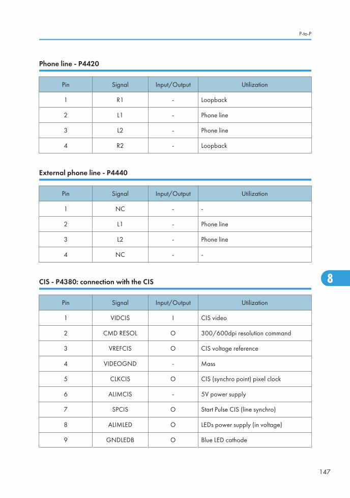
Phone line - P4420
Pin Signal Input/Output Utilization
1 R1 - Loopback
2 L1 - Phone line
3 L2 - Phone line
4 R2 - Loopback
External phone line - P4440
Pin Signal Input/Output Utilization
1 NC - -
2 L1 - Phone line
3 L2 - Phone line
4 NC - -
CIS - P4380: connection with the CIS
Pin Signal Input/Output Utilization
1 VIDCIS I CIS video
2 CMD RESOL O 300/600dpi resolution command
3 VREFCIS O CIS voltage reference
4 VIDEOGND - Mass
5 CLKCIS O CIS (synchro point) pixel clock
6 ALIMCIS - 5V power supply
7 SPCIS O Start Pulse CIS (line synchro)
8 ALIMLED O LEDs power supply (in voltage)
9 GNDLEDB O Blue LED cathode
P-to-P
147
8

Pin Signal Input/Output Utilization
10 GNDLEDV O Green LED cathode
11 GNDLEDR O Red LED cathode
12 GND - Ground
USB - P4901: USB slave interface
Pin Signal Input/Output Utilization
1 VBUS_USB I Power supply provided by the master
2 USBN I/O Differential pair
3 USBP I/O Differential pair
4 GND I/O Ground
USB - P4950: USB master interface
Pin Signal Input/Output Utilization
1 VBUS_USB_HOST O Power supply provided to the slave
2 USBN I/O Differential pair
3 USBP I/O Differential pair
4 GND I/O Ground
USB - P4960: USB master interface
Pin Signal Input/Output Utilization
1 VBUS_USB_HOST_2 O Power supply provided to the slave
2 USBN I/O Differential pair
3 USBP I/O Differential pair
4 GND I/O Ground
8. Apppendix
148
8