Embed Size (px)
Citation preview
HS2P(Machine Code: G407/G408/G410/G411)
Service Manual
Issued on 22nd December 1998Ricoh Co., Ltd
�IMPORTANT SAFETY NOTICES1. Before disassembling or assembling parts of the scanner and peripherals,
make sure that the scanner power cord is unplugged.2. The wall outlet should be near the scanner and easily accessible.3. The output voltage of the PSU (Power Supply Unit) can be either 100 ~ 120
Vac or 220 ~ 240 Vac, without any adjustment. Make sure that the abovevoltage is used.
4. The power cord should be an approved type, in accordance with theregulations for the country in which the scanner is used.
5. The use of cables other than the shield I/O cables or equivalent specified willinvalidate the certification of this scanner and may cause interference levelswhich exceed the limits established for this equipment.
Maintenance InformationThe user’s manual explains how to use and maintain the scanner. Beforeperforming the maintenance, read the user’s manual.
Warning concerning copyrightMany documents are copyrighted. Such documents may not be reproduced byscanning or in any other form without the express permission of the copyrightholder.
NoticeThe contents of this manual are subject to change without notice.

i
TABLE OF CONTENTS
1. OVERALL MACHINE INFORMATION ........................................1-11.1 SPECIFICATIONS.....................................................................................1-1
1.1.1 MAIN BODY......................................................................................1-11.1.2 ENDORSER .....................................................................................1-2
1.2 COMPONENT LAYOUT ............................................................................1-31.2.1 FRONT VIEW ...................................................................................1-31.2.2 REAR VIEW......................................................................................1-41.2.3 ADF ..................................................................................................1-5
1.3 DRIVE LAYOUT ........................................................................................1-61.3.1 SCANNER ........................................................................................1-61.3.2 ADF ..................................................................................................1-7
1.4 ELECTRICAL COMPONENT LAYOUT .....................................................1-81.4.1 SCANNER ........................................................................................1-81.4.2 ADF ..................................................................................................1-9
2. DETAILED SECTION DESCRIPTIONS.......................................2-12.1 INITIALIZATION ........................................................................................2-12.2 SCANNER MECHANISMS........................................................................2-3
2.2.1 BOOK MODE....................................................................................2-32.2.2 ADF MODE.......................................................................................2-7
2.3 PAPER MISFEED DETECTION..............................................................2-142.4 IMAGE PROCESSING ............................................................................2-16
2.4.1 OVERVIEW ....................................................................................2-162.4.2 SBU ................................................................................................2-172.4.3 IPU (IMAGE PROCESSING UNIT).................................................2-18
2.5 REVERSE SIDE SCANNING ..................................................................2-212.5.1 OVERVIEW ....................................................................................2-212.5.2 CIS (CONTACT IMAGE SENSOR) UNIT .......................................2-222.5.3 IMAGE SCANNING ........................................................................2-23
2.6 ENDORSER UNIT ...................................................................................2-242.6.1 OVERVIEW ....................................................................................2-242.6.2 ENDORSER UNIT ..........................................................................2-25
2.7 LOW POWER MODE ..............................................................................2-262.8 MAIN PCBs AND THEIR FUNCTIONS ...................................................2-27
2.8.1 BOARD STRUCTURE....................................................................2-272.8.2 SCU (SCANNER CONTROL UNIT) ...............................................2-282.8.3 IOB (INPUT/OUTPUT BOARD) ......................................................2-292.8.4 ADU (ADF DRIVE UNIT) ................................................................2-30

ii
3. INSTALLATION...........................................................................3-13.1 ENVIRONMENT ........................................................................................3-1
3.1.1 PRECAUTIONS................................................................................3-13.1.2 ENVIRONMENTAL CONDITIONS ...................................................3-13.1.3 MACHINE LEVEL .............................................................................3-13.1.4 MINIMUM SPACE REQUIREMENTS...............................................3-13.1.5 POWER REQUIREMENTS ..............................................................3-2
3.2 SCANNER INSTALLATION.......................................................................3-23.3 IPU UNIT INSTALLATION.........................................................................3-23.4 ENDORSER UNIT INSTALLATION...........................................................3-3
3.4.1 ACCESSORY CHECK......................................................................3-33.4.2 INSTALLATION PROCEDURE ........................................................3-43.4.3 STAMP DENSITY ADJUSTMENT PROCEDURE ............................3-6
3.5 RED LAMP UNIT INSTALLATION.............................................................3-73.5.1 ACCESSORY CHECK......................................................................3-73.5.2 INSTALLATION PROCEDURE ........................................................3-8
4. SERVICE LEVEL FUNCTIONS ...................................................4-14.1 DIP SWITCH SETTINGS...........................................................................4-14.2 LEDs/TEST POINTS .................................................................................4-6
4.2.1 LEDs.................................................................................................4-64.2.2 TEST POINTS ..................................................................................4-6
4.3 SPECIAL TOOLS ......................................................................................4-6
5. REPLACEMENT AND ADJUSTMENT ........................................5-15.1 COVERS ...................................................................................................5-1
5.1.1 ADF EXTERIOR ...............................................................................5-15.1.2 ADF COVER.....................................................................................5-25.1.3 SCANNER EXTERIOR/OPERATION PANEL ..................................5-3
5.2 ADF AND UPPER SIDE ............................................................................5-45.2.1 DOCUMENT SENSOR.....................................................................5-45.2.2 SEPARATION UNIT .........................................................................5-45.2.3 DOCUMENT TABLE ASSEMBLY ....................................................5-55.2.4 CIS....................................................................................................5-55.2.5 SCANNING GUIDE PLATE ..............................................................5-65.2.6 FEED SENSOR................................................................................5-65.2.7 READ SENSOR................................................................................5-75.2.8 FEED-OUT SENSOR .......................................................................5-75.2.9 PAPER TRANSPORT DRUM...........................................................5-8
5.3 ADF AND RIGHT SIDE .............................................................................5-95.3.1 PAPER FEED MOTOR.....................................................................5-95.3.2 EDU ..................................................................................................5-95.3.3 ENDORSER SOLENOID................................................................5-105.3.4 RELAY SENSOR............................................................................5-10
5.4 ADF AND LEFT SIDE..............................................................................5-115.4.1 ADU/PAPER TRANSPORT MOTOR..............................................5-11

iii
5.4.2 DOCUMENT TABLE POSITION SENSOR.....................................5-115.4.3 PICK-UP CLUTCH/DOCUMENT TABLE LIFT CLUTCH................5-12
5.5 SCANNER ...............................................................................................5-135.5.1 EXPOSURE GLASS.......................................................................5-135.5.2 EXPOSURE LAMP .........................................................................5-145.5.3 SBU/LAMP STABILIZER/SCANNER MOTOR/PSU .......................5-155.5.4 IOB .................................................................................................5-165.5.5 SOP ................................................................................................5-175.5.6 HOME POSITION SENSOR...........................................................5-175.5.7 ADF INTERLOCK SWITCH............................................................5-185.5.8 SCANNER WIRE............................................................................5-19
5.6 PCB .........................................................................................................5-225.6.1 SCU/RCU/IPU ................................................................................5-22
6. TROUBLESHOOTING.................................................................6-16.1 SELF-DIAGNOSTICS................................................................................6-16.2 CHECK ITEMS ..........................................................................................6-1
6.2.1 ITEMS CHECKED DURING INITIALIZATION..................................6-16.3 ERROR INDICATION................................................................................6-2
6.3.1 USER LEVEL ERROR INDICATION ................................................6-26.3.2 TECHNICIAN LEVEL ERROR INDICATION ....................................6-2
6.4 TROUBLESHOOTING PROCEDURES ....................................................6-36.4.1 USER-VISIBLE ERROR CONDITIONS............................................6-36.4.2 SERVICE CALL ERRORS (SYSTEM ERRORS) .............................6-8
6.5 INDICATION WHEN A CONNECTOR IS OUT OF POSITION................6-146.5.1 SCANNER ......................................................................................6-146.5.2 ADF ................................................................................................6-15
6.6 BLOWN FUSE CODITIONS ....................................................................6-16
7. OPTION .......................................................................................7-17.1 IPU (IMAGE PROCESSING UNIT)............................................................7-1
7.1.1 OVERVIEW ......................................................................................7-17.2 IMAGE PROCESSING PATH....................................................................7-2
22 December 1998 SPECIFICATIONS
1-1
Ove
rall
Info
rmat
ion1. OVERALL MACHINE INFORMATION
1.1 SPECIFICATIONS
1.1.1 MAIN BODY
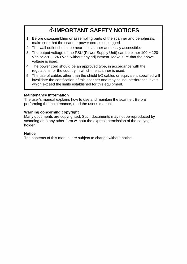
Scanning method: Flat-bed with ADF
Book scan: Horizontal: Max. 298 mm [11.7"]Vertical: Max. 432 mm [17.0"]
ADF: Document size:Width: 69 ~ 298 mm [2.7" ~ 11.7"]Length: 120 ~ 2,000 mm [4.7" ~ 78.5"]
All pages in a document must be thesame width
Document weight: 41 ~ 128 g/m2 [11 ~ 34 lb.]ADF capacity:
150 sheets (64 g/m2 [20 lb.])110 sheets (105 g/m2 [24 lb.]/A4, A5, LT, HLT) 80 sheets (105 g/m2 [24 lb.]/A3, DLT)Stack height must be less than 15 mm [0.6"]
Scanning resolution: Simplex mode:Main scan: 100 ~ 800 dpi (in 1 dpi steps)Sub scan: 100 ~ 800 dpi (in 1 dpi steps)
Duplex mode:Main scan: 100 ~ 600 dpi (in 100 dpi steps)Sub scan: 100 ~ 600 dpi (in 100 dpi steps)
Grayscales: 8 bits/pixel
Initialization time: About 15 seconds
Scanning speed: 0.65 s/200 dpi (A4, binary picture mode)
Scanning throughput: Simplex mode: 55 ppm/200 dpi(A4, binary picture mode)
Duplex mode: 86 ipm/200 dpi(A4, binary picture mode)
(Counted from the second page)
Interface: SCSI-2
Power: 1) 102 to 138 V ac (45 to 65 Hz)2) 187 to 276 V ac (45 to 65 Hz)
Power consumption(without all possible options):
Simplex model Standby: 50 W Max.Scanning: 90 W Max.Low power mode: 12 W Max.
Duplex model Standby: 80 W Max.Scanning: 120 W Max.Low power mode: 12 W Max.
SPECIFICATIONS 22 December 1998
1-2
Operating environment: Temperature: 10 to 32°C [50 to 90°F]Humidity: 20 to 80% RH
Weight: Simplex Model: Less than 25 kg [55.1 lb.]Duplex Model: Less than 26 kg [57.3 lb.](Add 1 kg [2.2 lb.] when the Endorser is installed.)
Dimensions (W x D x H): 470 x 677 x 278 mm [18.5" x 26.7" x 10.9"]
1.1.2 ENDORSER
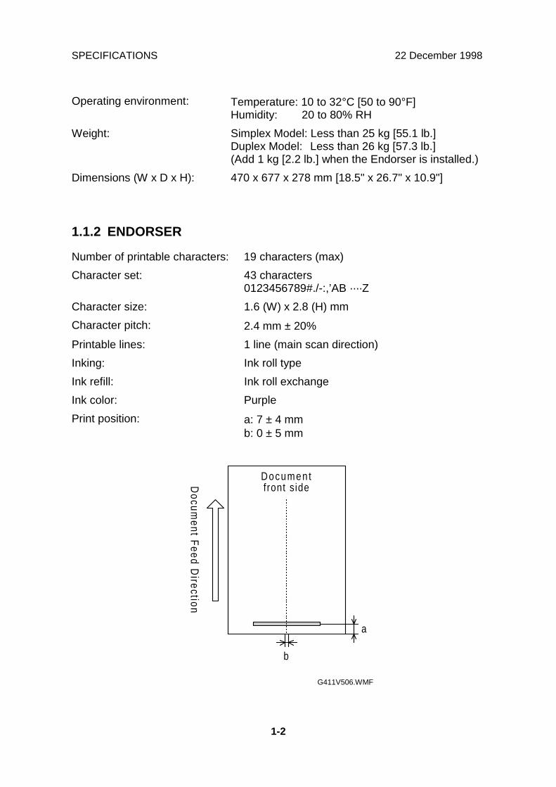
Number of printable characters: 19 characters (max)
Character set: 43 characters0123456789#./-:,’AB ····Z
Character size: 1.6 (W) x 2.8 (H) mm
Character pitch: 2.4 mm ± 20%
Printable lines: 1 line (main scan direction)
Inking: Ink roll type
Ink refill: Ink roll exchange
Ink color: Purple
Print position: a: 7 ± 4 mmb: 0 ± 5 mm
Documentfront sideD
ocument F
eed Direction
a
b
G411V506.WMF

22 December 1998 COMPONENT LAYOUT
1-3
Ove
rall
Info
rmat
ion
1.2 COMPONENT LAYOUT
1.2.1 FRONT VIEW
No. Name Function
1Platen cover Covers the document and serves as a neutral
background for documents placed on the mainexposure glass.
2 ADF exposure cover Covers the scanner and closes the ADF exposurecover interlock switch. Also contains an exposure glass.
3 Scale Used for positioning a document when placing it on theexposure glass.
4 Scanner indicator lamps The green and red lights indicate the condition of thescanner.
5 Power switch Turns the power on and off.
6 Main exposure glass A document to be scanned in book mode is placed facedown on this glass.
G411V500.WMF
1
2
35
4
6

COMPONENT LAYOUT 22 December 1998
1-4
1.2.2 REAR VIEW
No. Name Function7 Reset switch If this is pressed, the machine is reset.
8 DIP switches Used to select various scanning modes and testmodes.
9Interface for reverse sidescanning(Duplex model only)
Interface for the video signal during reverse sidescanning.
10 SCSI connectors For connecting the SCSI cables.
11SCSI ID rotary switch Used to select the SCSI ID and to select diagnostic
tests. Note that positions 8 and 9 are interpreted asSCSI ID 7.
12 Power plug inlet For connecting the power cord.
13 ADF cover Open this cover to clear paper jammed at the inputside.
G411V501.WMF
13
101112 789

22 December 1998 COMPONENT LAYOUT
1-5
Ove
rall
Info
rmat
ion
1.2.3 ADF
No. Name Function
14 ADF Automatically feeds multi-page documents into thescanner.
15 Document table Documents to be scanned using the ADF are placedhere.
16 Document guides Used to properly align the documents placed in theinput tray.
17 Exit table Receives documents fed by the ADF after scanning.
18 Exit table extension This holds the documents output from the ADF; it canbe extended to support long documents.
19 Endorser cover Open this cover to clean the endorser or replace theink.
20 Document support wire If long documents are placed in the input tray, this helpsto feed them correctly.
G411V502.WMF
1514
16
17
19
18
20

DRIVE LAYOUT 22 December 1998
1-6
1.3 DRIVE LAYOUT
1.3.1 SCANNER
No. Name Function
1First scanner Moves the exposure lamp along the document and
sends the light reflected from the document to the 2ndscanner by means of a mirror.
2Second scanner Moves to keep the distance between the exposure lamp
and the CCD constant, and sends light reflected fromthe 1st scanner to the CCD.
3 Scanner drive wires Transmit motor power to the 1st and 2nd scanners.4 Wire springs Tighten the scanner drive wires.5 Motor belt Transmits motor power to the scanner drive wires.6 Scanner motor Drives the scanners.7 Pulleys Hold the scanner drive wires.
G411V503.WMF
7
7
7
4
6
23
5
7
4
1

22 December 1998 DRIVE LAYOUT
1-7
Ove
rall
Info
rmat
ion
1.3.2 ADF
No. Name Function8 Feed roller Feeds the top page of the original into the ADF.
9 Pick-up roller Picks up and transports the top page of the original onthe document table.
10 Separation roller Stops the lower pages of the original while allowing thetop one to pass.
11 White roller(Duplex model only)
Allows the machine to correct for variations in the whitelevel of the CIS.
12 Feed-out rollers Feed the scanned original onto the exit table.13 Paper transport drum Transports the original to the scanning position.14 Paper transport rollers Hold the original against the paper transport drum.
G411V507.WMF
11
12
10
9
13
148

ELECTRICAL COMPONENT LAYOUT 22 December 1998
1-8
1.4 ELECTRICAL COMPONENT LAYOUT
1.4.1 SCANNER
No. Name Function
1 Home position sensor Detects whether the first scanner is at the homeposition.
2 SCU Controls the overall scanner function.3 Lamp Stabilizer Provides ac power to the exposure lamp.
4 SBU Contains the CCD, and outputs a video signal to theSCU.
5 Scanner Motor Drives the scanners.6 SOP This contains the scanner indicator lamps.7 PSU Provides dc voltages to the system.8 IOB Controls the mechanical parts of the scanner.
9 IPU Board (Option) Performs automatic text/image separation, dynamicthreshold, section area, and document size detection.
10 RCU(Duplex Model only)
Outputs a video signal of the reverse side of the originalto the SCU.
11 Exposure lamp Illuminates the original for exposure.
G411V504.WMF
6
7
5
4
3
2
1
8
9
10
11

22 December 1998 ELECTRICAL COMPONENT LAYOUT
1-9
Ove
rall
Info
rmat
ion
1.4.2 ADF
No. Name Function
12 ADF interlock switch Detects whether the ADF cover and platen cover areopen or closed; cuts the power supply to the machine.
13 Paper transport motor Drives the paper transport drum.
14 Feed sensor Detects when a document is just before the feedingposition.
15 Read sensor Synchronizes the original exposure timing.16 Paper feed motor This drives the pick-up and feed rollers.
17 CIS (Duplex model only) Contains the CCDs and LEDs that scan the reverseside of the original.
18 EDU (Option) Controls the mechanical parts of the endorser.
19 Endorser solenoid(Option)
Moves the paper holding plate to hold the original at theendorser’s printing position.
20 Relay sensor Checks for original misfeeds.21 Feed-out sensor Detects when a document is at the feed-out position.
22 Document sensor Detects when a document is placed on the documenttable.
23 ADU Controls the mechanical parts of the ADF.
24 Document table positionsensor
Detects if the document table is at the feed position ornot.
25 Pick-up clutch Controls pick-up roller rotation.
26 Document table liftclutch
Switches on to lift the document table up or down.
G411V505.WMF
19
18
17
16
15
14
13
26
20
21
22
23
24
25
12

22 December 1998 INITIALIZATION
2-1
Det
aile
dD
escr
iptio
ns
2. DETAILED SECTION DESCRIPTIONS
2.1 INITIALIZATION
Power on
Is the memory OK?User Level: System error
Service Level: Memory error
Initialize the I/O port, E 2PROM,IPU, and memory control ler
Yes
Turn on the lamp
Is thehome posit ion check
O K ?Home posit ion error
Scan the white plate
Lamp error
Has theinit ial ization procedure been
tried three t imes?
Are theADF or the document feeder
cover c losed?ADF open error
Is anyone of the feed, read, or feed-
out sensors on?Paper jam
Is thereany paper on the document
table?
Is the documenttable working properly?
Document table error
Detects document
Init ialize the scanner motor
Yes
1
2
3
4
5
6
7
8
9
11
12
13
14
Yes
No
N o
N o
N o
N o
Yes
N o N o
Adjust the black level
Endorser motor turns on for 0.1s10
Yes
Yes
Were there anyshading, or lamp, errors?
Is thewhite level within specified
value?
User Level: System errorService Level: Memory error
Use the default value of the whiteand black levels
Yes
No
No
R E A D Y
Yes Yes
G411D503.WMF
INITIALIZATION 22 December 1998
2-2
During power-up initialization, the scanner performs the following steps (refer to theflow chart on the previous page).
1. Tests the ROM checksum and makes a RAM read/write test. If the CPU cannottest these, the CPU determines that a memory error has occurred.
2. Initializes the I/O port, E2PROM, and gate arrays (IPU and memory controller).
3. Initializes the scanner motor driver.
4. Checks the home position sensor signal timing while moving the scanners. Ifthe CPU does not detect a signal change within the specified period, itdetermines that a home position error has occurred.
5. Adjusts the difference between the even and odd black levels and total blacklevel.
6. Turns the exposure lamp on.
7. Adjusts the white level, and checks the peak level of the auto gain control. If theCPU cannot adjust them to the specified levels, the CPU determines that alamp error has occurred.
8. If the black level or the white level cannot be adjusted properly during theabove initialization process, the scanner retries the initialization up to threetimes. If the CPU detects an abnormal condition at the third time (step 14), theCPU stores the default values of the black and white levels into the NVRAM onthe SCU.
9. Checks the ADF interlock switch signal. If the CPU detects that the switch isopen, it determines that an ADF open error has occurred.
10. When the endorser unit has been installed, the endorser motor turns on for 0.1second.
11. Checks the signals from the feed, read, and feed-out sensors. If any of themare on, the CPU determines that there is a paper jam.
12. Checks the document sensor signal. If the CPU detects a document on thedocument table, check #13 is not made until the document is removed.
13. Checks the document table position sensor signal timing while lifting andlowering the document table.
14. See step 8.
22 December 1998 SCANNER MECHANISMS
2-3
Det
aile
dD
escr
iptio
ns
2.2 SCANNER MECHANISMS
2.2.1 BOOK MODE
Overview
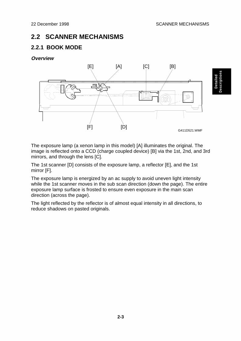
The exposure lamp (a xenon lamp in this model) [A] illuminates the original. Theimage is reflected onto a CCD (charge coupled device) [B] via the 1st, 2nd, and 3rdmirrors, and through the lens [C].
The 1st scanner [D] consists of the exposure lamp, a reflector [E], and the 1stmirror [F].
The exposure lamp is energized by an ac supply to avoid uneven light intensitywhile the 1st scanner moves in the sub scan direction (down the page). The entireexposure lamp surface is frosted to ensure even exposure in the main scandirection (across the page).
The light reflected by the reflector is of almost equal intensity in all directions, toreduce shadows on pasted originals.
G411D521.WMF[F] [D]
[B][C][A][E]

SCANNER MECHANISMS 22 December 1998
2-4
Scanner Drive
The scanner drive motor [A] (a stepper motor) drives the 1st and 2nd scanners [B,C] through the timing belt [D], scanner drive pulley [E], scanner drive shaft [F], andtwo scanner wires [G].
The IOB board drives the scanner drive motor. The scanning speed depends onthe scanning resolution. The returning speed depends on the distance from thehome position sensor.
G411D522.WMF[D]
[B]
[F]
[A]
[C]
[G]
[G]
[E]

22 December 1998 SCANNER MECHANISMS
2-5
Det
aile
dD
escr
iptio
ns
Basic Scanning Procedure
When the scan command is received from the host computer, the scanner startsscanning as explained in the following steps.
Initialization
The scanner checks the home position, scanner cover, and memory. If an error isdetected, the scanner motor will stop.
The scanner scans the white plate [A] on the underside of the ADF exposure coverto perform the shading function.
Image Scanning
The scanner starts to scan the image area at the designated position [B]. Thescanner stops after scanning the designated image area [C]. The arrows indicatethat the scan start position and image area depend on the settings input by theuser.
Scanner Reversing
After the image has been scanned, the scanners return to the home position [D].
The scanners are stopped when the first scanner activates the home positionsensor [E]. If the scanner home position sensor is not activated within a certaintime, a home position sensor error will occur.
G411D524.WMF[D]
[G]
[A]
[F]
[B][E]
[C]

SCANNER MECHANISMS 22 December 1998
2-6
Optional Steps (Optional IPU Board)
Size Detection
If selected, this is done after the ‘Initialization’ step.
1) Main Scan Direction (Document Width)The first scanner moves to the book mode standard position ([F] on the previouspage). Then, the scanner scans 5 mm from the book mode standard position.
The scanner determines the document width in the main scan direction from theoutput signal level. The edge of the document is detected by the differencebetween the level of the document data and the background signal which isprovided by the silver plate [G] attached to the platen cover across the main scan.
If there is a gap at the leading edge, such as a tear (or a black stripe), extendingmore than 1 mm across the paper and more than 5 mm down the paper, themachine cannot detect the document width past this gap. In this case, an errormessage may appear, and scanning is impossible. . Disable this feature to allowthe machine to scan this document.
2) Sub Scan Direction (Document Length)
The scanner detects the document size only in the main scan direction, and thescanner driver determines that the document length is the same as for a standardpaper size of the same width.NOTE: The scanner always assumes the paper is in a lengthwise orientation (i.e.,
the main scan is the short side). Also, in USA models, if Letter width isdetected, the paper is always assumed to be Letter size (this means thatthe last few inches of a Legal-size original will not be scanned).
Read Size Command
If selected, this is done after the ‘Initialization’ step.
1) Read Size CommandIf the scanner receives the Read Size command in book mode, it detects the sizein the main scan direction as described above.
The scanner sends the width data to the host computer.
After detecting the document size, the scanner scans the detected area.
Abort Command
This can occur at any time during the basic scanning procedure.
If the Abort command is received during scanning, the scanner motor is stopped.Then the scanner returns to the home position ([D] in the previous diagram).
If this command is received while the scanner is reversing or checking the homeposition, the operation is not interrupted.

22 December 1998 SCANNER MECHANISMS
2-7
Det
aile
dD
escr
iptio
ns
2.2.2 ADF MODE
Overview
When the originals are placed on the document table [A], the document sensor [B]detects them. The pick-up roller [C] picks up the originals and transports them tothe feed roller [D]. The separation roller [E] turns in the opposite direction to thefeed roller. As a result, just one original is sent to the paper transport drum [G]. Thefeed sensor [F] detects whether the original has reached the transport drum or not.Then the original turns with the transport drum through the read sensor [H]. Whilethe original passes over the ADF scanning position [J], the scanner [K] reads theoriginal. After reading, the original goes to the exit table [N]. The feed-out sensor[M] detects whether the original is fed out or not. The relay sensor [L] detects whenan original is jammed in the area between the read sensor and the feed-outsensor. This sensor is monitored at all times except when the ADF is feeding adocument.
G411D517.WMF
[B][C]
[F]
[D]
[G]
[H]
[I][J]
[K]
[M]
[E]
[N]
[A]
[L]

SCANNER MECHANISMS 22 December 1998
2-8
Basic Scanning Procedure
When the scanner receives the ADF scanning command, the scanner scans theoriginal as described below.
1) ADF ModeThe scanner performs the home position check and the shading process. If a homeposition error is detected, the scanner [K] will stop immediately. If an ADF coveropen error or memory error is detected, the scanner will stop after returning to thehome position.
The first carriage moves to the ADF scanning position [J] from the scanner homeposition [I]. Then the paper transport motor starts.
2) SADF ModeThe scanner waits until the designated time for the originals to be placed on thedocument table [A].
When the originals have been placed on the document table, the same procedureas for ADF mode is carried out.

22 December 1998 SCANNER MECHANISMS
2-9
Det
aile
dD
escr
iptio
ns
Document Table Lift
The lift mechanism consists of the document table lift clutch [A], the lift shaft [B],the document table position sensor [C], and the sensor actuator on the gear [D].
In standby mode, the bend in the lift shaft [H] is pointing downwards and theactuator is just inside the sensor.
When an original is placed on the document table, the document sensor [E] isactivated. Then the paper feed motor [G] turns on. At the same time, the documenttable lift clutch [A] turns on to rotate the lift shaft.
At this time, the actuator starts to turn anticlockwise, and the flat part of the spring[I] that is loosely attached to the bend in the lift shaft pushes up the document table(see the next page for a diagram).
When the top of the document stack is pushed up against the pick-up roller, it canrise no more. However, the mechanism continues to push up against the tray untila half-turn of the shaft has been completed (i.e., until the actuator leaves thedocument table position sensor). At that time, the document table lift clutch and thepaper feed motor turn off. If the actuator does not leave the sensor within a certaintime, a document table error will occur.
The feed motor turns on again at a motor speed which depends on the scanningresolution, and the pick-up clutch [F] turns on to feed the top sheet of the original(see Original Feed and Separation).
G411D518.PCX
[C]
[G]
[F]
[A]
[D][B] [E]
[F][A]
[H]

SCANNER MECHANISMS 22 December 1998
2-10
When the first original is being fed, the bend in the lift shaft is pointing up, and thespring is at maximum compression. As sheets of the document are scanned, thespring pushes the document table upwards so that the top of the stack is alwaysagainst the pick-up roller.
When all pages of the original have been fed out of the ADF, the document tablelift clutch and paper feed motor are energized to lower the tray. They turn off whenthe document table sensor is deactivated. If the sensor is not deactivated within thedesignated time, a document table error will occur.
G411D519.WMF
[H]
[I]

22 December 1998 SCANNER MECHANISMS
2-11
Det
aile
dD
escr
iptio
ns
Original Feed and Separation
To feed the original, the paper feed motor and the paper transport motor (whichdrives the paper transport drum) turn on. The paper feed motor drives the pick-uproller [A] through a train of gears and the pick-up clutch [B]. The pick-up clutchturns on to feed the top sheet of the original. If the pick-up roller feeds multiplepages of the original, the separation roller [C] and the feed roller [D] separate thesepages (the separation mechanism is friction-based).
When the leading edge of the original activates the feed sensor [E], the paper feedmotor and the pick-up clutch turn off, then the paper transport drum [F] feeds theoriginal to the scanning position.
Image Scanning
The scanner starts to scan the image when the leading edge has passed the readsensor by a certain distance (measured by motor pulses).
When the CPU has fed the trailing edge of the original 30 mm past the feed-outsensor, the transport motor turns off.
G411D520.WMF
[C]
[E]
[F]
[D]
[A]
[B]

SCANNER MECHANISMS 22 December 1998
2-12
Optional Steps
Size Detection
If selected, this is done after document table lift/paper feed.
1) Main Scan Direction (Document Width)This function will be available when the optional IPU board is installed.
First of all, the original is fed to the scan ready position between the read sensor[B] and the size detection position [C]. Then the first scanner moves to the sizedetection position [C] from the ADF scanning position [D]. After that, the original isfed to the ADF scanning position.
As a result of the above operation, the original is fed 5 mm past the first scanner.Then the CPU detects the original width. The edge of the document is detected bythe difference between the level of the document data and the background level,which is provided by the black bracket located over the ADF exposure cover.
If there is a gap at the leading edge, such as a tear (or a black stripe), extendingmore than 1 mm across the paper and more than 5 mm down the paper, themachine cannot detect the document width past this gap. In this case, an errormessage may appear, and scanning is impossible. Disable this feature to allow themachine to scan this document.
After finishing the above operation, the first scanner returns to the ADF scanningposition.
2) Sub Scan Direction (Document Length)The length of the original is calculated by counting the motor pulses while the feedsensor [A] is on. (The length is detected during scanning.)
G411D523.WMF
[A]
[B]
[D] [C]

22 December 1998 SCANNER MECHANISMS
2-13
Det
aile
dD
escr
iptio
ns
Read Size Command
If selected, this is done after document table lift/paper feed.
If the scanner receives a Read Size command in ADF mode, it detects thedocument size in the main scan direction as described on the previous page.
The scanner sends the width data to the host computer.
Abort and Unload Commands
These can occur at any time during the basic scanning procedure.
When the CPU receives the Abort or the Unload command during paper transport,the scanner feeds out any original that is in the ADF.

PAPER MISFEED DETECTION 22 December 1998
2-14
2.3 PAPER MISFEED DETECTION
FGATE: When this signal is high, scanned data is valid
Unit: milliseconds
t1 t2 t3 t4 t5 t6
200 dpi Within3,000
210 205 44 24.64 L x 0.011x 200
400 dpi Within3,000 210 205 88 172.04 L x 0.011
x 400
L: Document length (mm)
Paper Feed Motor
Pick-up Clutch
Document Tab leLift Clutch
Document Tab lePosi t ion Sensor
Document Sensor
Paper Transpor tMotor
Feed Sensor
Read Sensor
Feed-out Sensor
F G A T E
Start
t1
t2Orig inal End
t3
t5 t6
J3
J6
J2
J5
J4
J1
M A X
R E A D
O F F
M A X
R E A D
O F F
G411D527.WMF

22 December 1998 PAPER MISFEED DETECTION
2-15
Det
aile
dD
escr
iptio
ns
J1: The leading edge of the original does not reach the feed sensor within the timerequired for feeding the distance between the pick-up roller and the feed sensor+ 150 mm after the pick-up clutch turned on.
J2: The leading edge of the original does not reach the read sensor within the timerequired for feeding the distance between the feed sensor and the read sensor+ 150 mm after the feed sensor was activated.
J3: The leading edge of the original does not reach the feed-out sensor within thetime required for feeding the distance between the read sensor and the feedout sensor + 30 mm after the read sensor was activated.
J4: The trailing edge of the original does not pass through the feed sensor withinthe time required for feeding the maximum original length (2 m) + 60 mm afterthe feed sensor was activated.
J5: The trailing edge of the original does not pass through the read sensor withinthe time required for feeding the original + 75 mm after the read was activated.
J6: The trailing edge of the original does not pass through the feed-out sensorwithin the time required for feeding the original length + 75 mm after the feed-out sensor was activated.
If an original jam or an original non-feed is detected, the paper transport motor,paper feed motor, and the exposure lamp turn off. Then, the appropriate LEDsinform the user of the machine’s status.
If an original remains in the ADF, the original is fed out and the paper transportmotor stops.

IMAGE PROCESSING 22 December 1998
2-16
2.4 IMAGE PROCESSING
2.4.1 OVERVIEW
The CCD generates two analog video signals. The SBU (Sensor Board Unit)converts these analog signals to 8-bit digital signals, then it sends these digitalsignals to the SCU (Scanner Control Unit) board through the IOB board. The IPU(Image Processing Unit) IC on the SCU does the image processing, then the imagedata goes to the computer through the Memory Control IC and the SCSI controller.
The CIS (Contact Image Sensor) unit in the duplex model for reverse-sidescanning outputs two digital signals. The IPU on the RCU (Reverse Control Unit)board does the image processing, then the image data goes to the computerthrough the SCU.
CC
D
SCU
CIS
C C D
(Duplex model only)
D R A M IPUMemoryControl
IC
SCSIControl
IC
SBU
IOB
RCU
IPU
MemoryControl
ICD R A M
G411D508.WMF
22 December 1998 IMAGE PROCESSING
2-17
Det
aile
dD
escr
iptio
ns
2.4.2 SBU
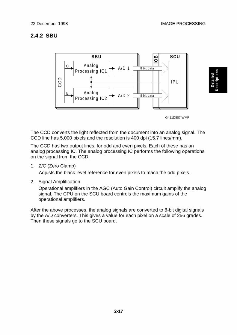
The CCD converts the light reflected from the document into an analog signal. TheCCD line has 5,000 pixels and the resolution is 400 dpi (15.7 lines/mm).
The CCD has two output lines, for odd and even pixels. Each of these has ananalog processing IC. The analog processing IC performs the following operationson the signal from the CCD.
1. Z/C (Zero Clamp)Adjusts the black level reference for even pixels to mach the odd pixels.
2. Signal AmplificationOperational amplifiers in the AGC (Auto Gain Control) circuit amplify the analogsignal. The CPU on the SCU board controls the maximum gains of theoperational amplifiers.
After the above processes, the analog signals are converted to 8-bit digital signalsby the A/D converters. This gives a value for each pixel on a scale of 256 grades.Then these signals go to the SCU board.
CC
DSBU
A/D 1
A/D 2
O
E
SCU
IOB
8 bit data
8 bit data
AnalogProcessing IC1
AnalogProcessing IC2
IPU
G411D507.WMF

IMAGE PROCESSING 22 December 1998
2-18
2.4.3 IPU (IMAGE PROCESSING UNIT)
Overview
The image data from the SBU goes to the IPU IC on the SCU board, which carriesout the following processes on the image data.
1. Auto shading
2. Magnification
3. Mirror processing
4. Filtering (MTF and smoothing)
5. γ (gamma) correction
6. Grayscale processing
7. Binary picture processing
8. Error diffusion
9. Dithering
10. White/black conversion
The image data then goes to the memory controller IC.
IPU
A D
A D
C
C
D
Selector
Odd
Even 8
MemoryControl ler
SCSI SCSI
S C USBU
OpionalIPU
8
8
8
IPU
AnalogProcess ing
IC 1
AnalogProcess ing
IC 2
8
G411D505.WMF

22 December 1998 IMAGE PROCESSING
2-19
Det
aile
dD
escr
iptio
ns
Image processing path
The following image processing is for the scanner (simplex model), not includingthe optional IPU. The image processing for each of these units is explained inseparate sections. However, when the optional IPU is installed, the IPU IC on theSCU only does the shading.
Shading CorrectionThe machine scans the white plate opposite the ADF exposure glass to make awhite waveform. Shading correction prevents uneven images caused byfluctuations in scanned data due to changes in light intensity and CCD sensitivity.
MagnificationReduction and enlargement in the sub scan direction are done by changing thescanner motor speed or paper transport motor speed in the ADF. However,reduction and enlargement in the main scan direction are done by the IPU.
Mirror Processing
A mirror image of the original must be made for output.
FilteringThere are two software filters: the MTF filter and the smoothing filter. The MTF filteremphasizes sharpness, and is used with text-only documents or documents thatcontain text and photo areas. The smoothing filter is used for photo-imagedocuments.
1. Without Optional IPU
2. With Optional IPU
IPUMemory
Control lerS B U
IPUOptional
IPUS B U
Shad ingcorrect ion
FilteringMagnif icat ion/Mirror Process
γ correct ionShad ing
correct ionDither/
Error Dif fusionBinary process
Whi te/b lackconvers ion
S C U
S C U
G411D500.WMF

IMAGE PROCESSING 22 December 1998
2-20
Gamma (γγ) CorrectionThe gamma curve corrects the response of the CCD to grayscales in the original.
Grayscale ProcessingThis process generates up to 256 image density levels for each pixel.
DitheringDither processing produces good quality grayscale images of photo originals.
Error DiffusionThe error diffusion process reduces the difference in contrast between light anddark areas of a halftone image. Each pixel is corrected using the differencebetween it and the surrounding pixels. The corrected pixels are then compared witha matrix table.
Binary Picture ProcessingEach video signal level is converted from 8-bit to 1-bit (black and white image data)in accordance with a threshold value.
White/Black Conversion
Inverts the image (converts from white to black and vice versa).
After video processing, the data goes to the host computer through the memoryand SCSI controllers.

22 December 1998 REVERSE SIDE SCANNING
2-21
Det
aile
dD
escr
iptio
ns
2.5 REVERSE SIDE SCANNING
2.5.1 OVERVIEW
The CIS (Contact Image Sensor) unit [A], which is in the document exit area, scansthe reverse side of the document.
The front side of the document is scanned first. Then the document goes to thereverse side scanning area. The white roller [B] pushes the document against theCIS unit for scanning and feeds the document to the exit area.
The position of the CIS unit is fixed in the scanner, and cannot be adjusted in thefield.
G411D516.WMF
[A]
[B]

REVERSE SIDE SCANNING 22 December 1998
2-22
2.5.2 CIS (CONTACT IMAGE SENSOR) UNIT
The CIS unit consists of the LED array (68 chips/line x 2 lines) [A], rod lens array[B], five CCDs [C], and the CIS drive board [D] (this contains the CCD drive circuit,analog processing circuit, A/D converter, shading correction IC, and LED drivecircuit). The CIS unit scans 4800 pixels in the main scan direction at a resolution of400 dpi (15.7 lines/mm).
There is a row of LEDs on each side of the CCD so that the light is of almost equalintensity in all directions. This reduces shadows at the edges of documents.
The five CCDs are arranged as shown above (viewed from directly above theoriginal feed path). The CCDs have dummy pixels at the ends, so to get acontinuous scan across the page, the CCDs have to overlap. However, as a result,a continuous line cannot be scanned across the page at the same time. Data isheld in memory and combined later.
In book mode when scanning the front side, the scanner may stop if the buffer fillsup. This may happen if the data is complex. Scanning may not start again inexactly the same place, due to mechanical inaccuracies. This is not a big problemwhen scanning the front side. However, for the reverse side, because a completescan line is not scanned at the same time, it could mean loss of data.
Because of this, reverse side scanning is only enabled at 6 reproduction ratios(expressed in the driver as dpi: 100, 200, 300, 400, 500, and 600 dpi). This isbecause there is not enough memory to buffer the data and calculate the pixels forthe resulting image at other resolutions without stopping the scanner.
G411D513.WMF
G411D528.WMF
[A]
[C]
[D]
[B]
[C]

22 December 1998 REVERSE SIDE SCANNING
2-23
Det
aile
dD
escr
iptio
ns
2.5.3 IMAGE SCANNING
As explained on the previous page, the CIS unit contains five CCDs. The analogsignal from each CCD goes to an analog processing IC. The function of the analogprocessing circuit is the same as for the SBU. After this, the analog signal isconverted to a digital signal by the A/D converter. Then, the data goes to theshading circuit for correction. After shading, the data is divided to two signals: Oddand Even. Then, these go to the IPU on the RCU board.
The RCU board contains the IPU and memory controller ICs for image processing.The image processing in the IPU is the same as for the IPU in the SCU except forthe shading correction.
After image processing, the data goes to the PC through the SCSI controller on theSCU.
A D
A D
A D
A D
A D
C
C
D
L
E
D
IPUShading
Correct ion
Odd
Even
8
8
MemoryController8
SCSI SCSI
R C U
CIS
8
S C U
AnalogProcessing
Circuit
AnalogProcessing
Circuit
AnalogProcessing
Circuit
AnalogProcessing
Circuit
AnalogProcessing
Circuit
G411D504.WMF
IPUMemory
Control lerC IS
Shad ingcorrect ion
R C U
FilteringMagnif icat ion/Mirror Process
γ correct ionDither/
Error Dif fusionBinary Process
Whi te/b lackconvers ion
G411D526.WMF

ENDORSER UNIT 22 December 1998
2-24
2.6 ENDORSER UNIT
2.6.1 OVERVIEW
The endorser unit [A] is located just before the exit roller [B]. The endorser unitprints up to 19 characters (which are input using the scanner driver) at the trailingedge of the document.
The endorser operates as follows.
1. The user inputs characters and enables the endorser function using thescanner driver.
2. The scanner operates in the normal ADF mode.
3. The paper transport motor stops at a certain time after the leading edge of thepaper passes through the feed-out sensor.
4. The endorser motor turns on.
5. The endorser solenoid [C] is energized and the paper holding plate [D] goesdown to hold the original.
6. The endorser prints the characters.
7. After printing, the endorser motor turns off.
8. The endorser solenoid is de-energized and the paper holding plate goes up torelease the original.
9. The paper transport motor turns on again, and the original is fed to the originaltray.
G411D516.WMF
G411D514.WMF
[B]
[A]
[C]
[D]
[A]
[D]

22 December 1998 ENDORSER UNIT
2-25
Det
aile
dD
escr
iptio
ns
2.6.2 ENDORSER UNIT
The endorser unit consists of the endorser motor [A], clutch [B], character belt [C],hammer unit [D], and ink roller [E].
The endorser motor drives the character belt and hammer unit and operates thehammer [F].
The clutch controls the print timing.
The ink roller always contacts the character belt and always supplies ink to the belt.When the ink is used up, the customer replaces only the ink roller.
G411D515.WMF
[B]
[F]
[C]
[A]
[E]
[D]

LOW POWER MODE 22 December 1998
2-26
2.7 LOW POWER MODE
When the scanner has been idle for 15 minutes (this interval cannot be adjusted),the scanner automatically enters low power mode. However, the scanner cannotenter low power mode when a document jam or system error exists.NOTE: The scanner can enter low power mode if the ADF cover and/or platen
cover is open or paper remains on the document table.
When the scanner enters low power mode, the PSU cuts the +24 V, +12 V, –12 Vand +5 Vs supplies, and continues to supply +5VE only. As a result, the scannerconsumes less than 12 W. The operation panel indicates that the machine is in lowpower mode with the following LEDs.
LED StatusPower on BlinkingMachine busy OffDocument in place OffError Off
The scanner returns to stand-by mode when the ADF cover and/or platen cover isopened and closed, or when the user places a document on the document table, orwhen a Read command is received from the computer.
Opera t ion Stand-by mode Low power mode
W
t
15 min.
1 2 W
G411D525.WMF

22 December 1998 MAIN PCBS AND THEIR FUNCTIONS
2-27
Det
aile
dD
escr
iptio
ns
2.8 MAIN PCBs AND THEIR FUNCTIONS
2.8.1 BOARD STRUCTURE
For the main function of each PCB, refer to the Electrical Component Layoutsection.
H.P Sensor
LampStabil izer
Operat ionPanel
Cool ingFan
ScannerMotor
S B U
ExposureLamp
Clutches
Sensors
Motors
A D U
IOB
S C U
R C U
CIS Unit
Endorser Unit
Opt ional IPU P S U
A D F
MainFrame
G411D509.WMF
MAIN PCBS AND THEIR FUNCTIONS 22 December 1998
2-28
2.8.2 SCU (SCANNER CONTROL UNIT)
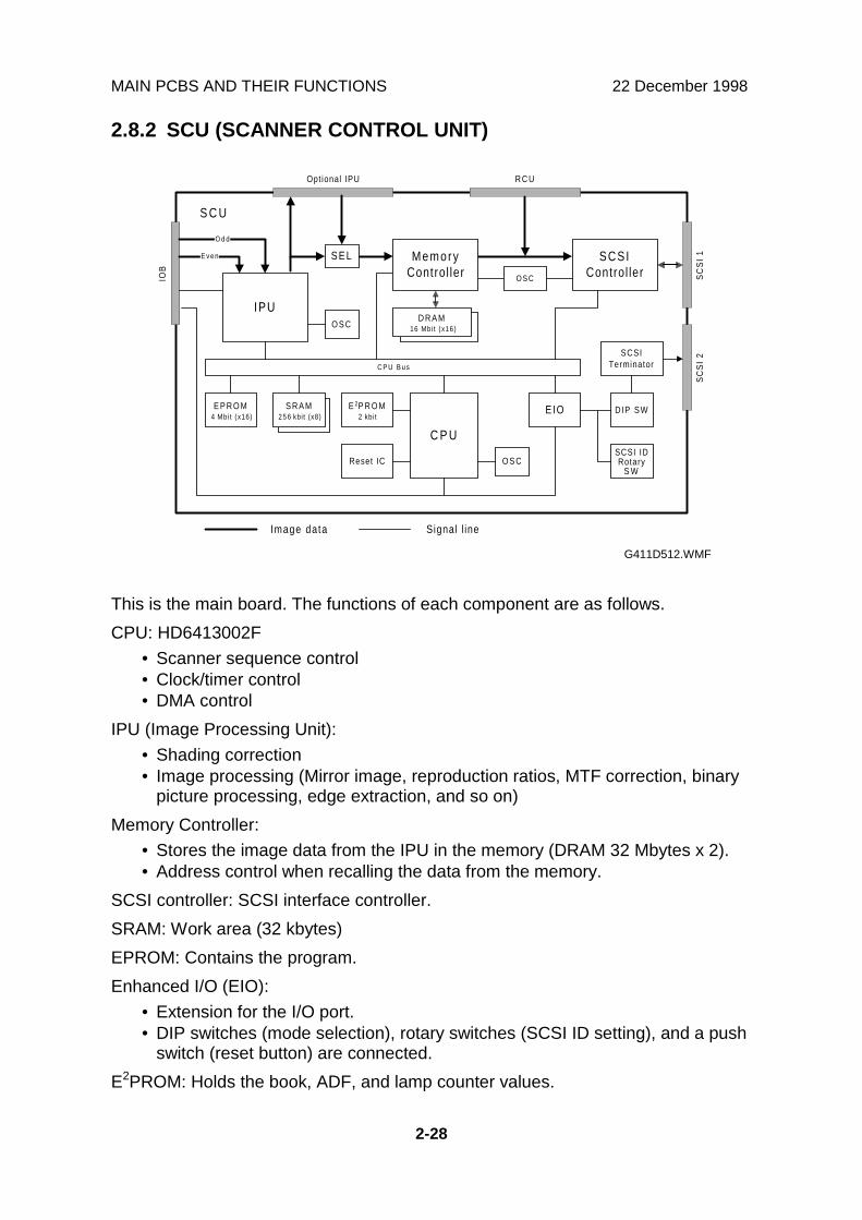
This is the main board. The functions of each component are as follows.
CPU: HD6413002F
• Scanner sequence control• Clock/timer control• DMA control
IPU (Image Processing Unit):
• Shading correction• Image processing (Mirror image, reproduction ratios, MTF correction, binary
picture processing, edge extraction, and so on)
Memory Controller:
• Stores the image data from the IPU in the memory (DRAM 32 Mbytes x 2).• Address control when recalling the data from the memory.
SCSI controller: SCSI interface controller.
SRAM: Work area (32 kbytes)
EPROM: Contains the program.
Enhanced I/O (EIO):
• Extension for the I/O port.• DIP switches (mode selection), rotary switches (SCSI ID setting), and a push
switch (reset button) are connected.
E2PROM: Holds the book, ADF, and lamp counter values.
IPU
SCSIControl ler
E P R O M4 Mbi t (x16)
S R A M2 5 6 kbi t (x8)
E 2P R O M2 kbit
Reset IC
C P U
EIO
SCSI IDRotary
S W
DIP SW
SCSITerminator
O S C
O S C
D R A M16 Mbi t (x16)
O d d
E v e n
C P U B u s
O S C
Optional IPU R C U
IOB
SC
SI
1S
CS
I 2
S C U
Image data Signal l ine
S E L MemoryControl ler
G411D512.WMF

22 December 1998 MAIN PCBS AND THEIR FUNCTIONS
2-29
Det
aile
dD
escr
iptio
ns
2.8.3 IOB (INPUT/OUTPUT BOARD)
The IOB contains the drive circuits for the scanner motor and the exposure lamp.The control signals such as drive and rotation direction, and drive current for thescanner motor come from the SCU. Also, the control signal for the exposure lampcomes from the SCU.
The image signals from the SBU go through this board to the SCU.
ScannerMotor
S B U
H.P Sensor
LampStabilizer
OperationPanel
ADU
Exposure Lamp
ScannerMotor Driver
Driver
Driver
Driver
+ 5V
+ 12V
+ 24V
+ 24V ADU
SC
U
IOB
InterlockSwitch
PSU
G411D510.WMF

MAIN PCBS AND THEIR FUNCTIONS 22 December 1998
2-30
2.8.4 ADU (ADF DRIVE UNIT)
The ADU drives the motors and clutches in the ADF unit. Also, it informs thesensor status to the SCU.
The SCU generates the control signals for each electrical component and theendorser, then these are sent to the ADU through the IOB. The drivers on the ADUconvert the control signals into drive pulses for the motors.
PaperTransport
Motor
Clutches
+ 5V
+ 12V
+ 24V ADU
- 12V
IOB
A D U
Sensors
PaperFeedMotor
E D U
CIS Unit
Motor Driver
Motor Driver
+ 5V
+ 24V ADU
+ 5V
+ 12V
- 12V
+ 15V
G411D511.WMF
22 December 1998 ENVIRONMENT
3-1
Inst
alla
tion
3. INSTALLATION
3.1 ENVIRONMENT
3.1.1 PRECAUTIONS
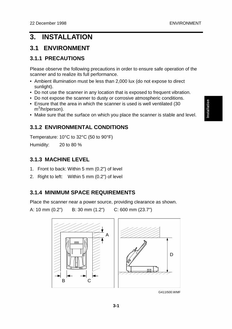
Please observe the following precautions in order to ensure safe operation of thescanner and to realize its full performance.
• Ambient illumination must be less than 2,000 lux (do not expose to directsunlight).
• Do not use the scanner in any location that is exposed to frequent vibration.• Do not expose the scanner to dusty or corrosive atmospheric conditions.• Ensure that the area in which the scanner is used is well ventilated (30
m3/hr/person).• Make sure that the surface on which you place the scanner is stable and level.
3.1.2 ENVIRONMENTAL CONDITIONS
Temperature: 10°C to 32°C (50 to 90°F)
Humidity: 20 to 80 %
3.1.3 MACHINE LEVEL
1. Front to back: Within 5 mm (0.2") of level
2. Right to left: Within 5 mm (0.2") of level
3.1.4 MINIMUM SPACE REQUIREMENTS
Place the scanner near a power source, providing clearance as shown.
A: 10 mm (0.2") B: 30 mm (1.2") C: 600 mm (23.7")
G411I500.WMF
CB
A
D

SCANNER INSTALLATION 22 December 1998
3-2
3.1.5 POWER REQUIREMENTS
�CAUTION1. Be sure to ground the scanner.2. Make sure the plug is firmly inserted in the outlet.3. Avoid multi-wiring.
1. Input voltage level:• 102 to 138 V ac (45 to 65 Hz)• 187 to 276 V ac (45 to 65 Hz)
2. Permissible voltage fluctuation: ± 10%
3.2 SCANNER INSTALLATION
Please refer to the scanner user’s manual for details.
3.3 IPU UNIT INSTALLATION
Please refer to the scanner user’s manual for details.

22 December 1998 ENDORSER UNIT INSTALLATION
3-3
Inst
alla
tion
3.4 ENDORSER UNIT INSTALLATION
3.4.1 ACCESSORY CHECK
Check the quantity and condition of the accessories in the box against the followinglist:
Description Q’ty
1. Endorser Unit ......................................................................... 1
2. Solenoid Ass’y........................................................................ 1
3. EDU Board ............................................................................. 1
4. Harness .................................................................................. 1
5. Ink Roller ................................................................................ 1
6. Decal ...................................................................................... 1
7. Screw - M3 x 6 ....................................................................... 2
8. Card Spacer ........................................................................... 1
9. Installation Procedure............................................................. 1
ENDORSER UNIT INSTALLATION 22 December 1998
3-4
3.4.2 INSTALLATION PROCEDURE
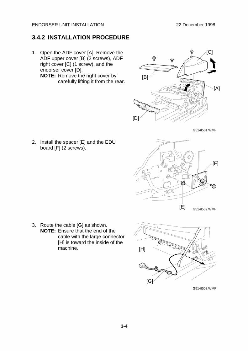
1. Open the ADF cover [A]. Remove theADF upper cover [B] (2 screws), ADFright cover [C] (1 screw), and theendorser cover [D].NOTE: Remove the right cover by
carefully lifting it from the rear.
2. Install the spacer [E] and the EDUboard [F] (2 screws).
3. Route the cable [G] as shown.NOTE: Ensure that the end of the
cable with the large connector[H] is toward the inside of themachine.
G514I501.WMF
G514I502.WMF
G514I503.WMF
[C]
[A]
[B]
[D]
[F]
[E]
[G]
[H]

22 December 1998 ENDORSER UNIT INSTALLATION
3-5
Inst
alla
tion
4. Install the solenoid assembly [I] asshown (3 screws).
5. Install the clamp [J] and connect thethree cables [K] to the EDU board [L].
6. Install the core [M].
7. Open the platen cover. Install theendorser unit [N], as shown (1connector).
8. Attach the decal [O].
9. Reinstall the endorser, right, and upper covers.
G514I504.WMF
G514I505.WMF
G514I506.WMF
[J]
[K]
[I]
[N]
[L]
[M]
[O]

ENDORSER UNIT INSTALLATION 22 December 1998
3-6
3.4.3 STAMP DENSITY ADJUSTMENT PROCEDURE
1. Open the ADF cover [A]. Remove theADF upper cover [B] (2 screws), ADFright cover [C] (1 screw), and theendorser cover [D].NOTE: Remove the right cover by
carefully lifting it from the rear.
2. Remove the solenoid assembly screw[E] from the hole [F] and replace it inhole [G]. Do not tighten the screw yet.
3. Loosen the screw [H] and adjust theheight of the bracket [I].NOTE: To reduce the stamp density,
raise the bracket. To increasethe density, lower the bracket.
4. Tighten the assembly screw [E] tosecure the bracket in the new position.
5. Reinstall the endorser, right, and uppercovers.
G514I501.WMF
G514I507.WMF
[C]
[A]
[B]
[D]
[E]
[I]
[G]
[F]
[H]
22 December 1998 RED LAMP UNIT INSTALLATION
3-7
Inst
alla
tion
3.5 RED LAMP UNIT INSTALLATION
3.5.1 ACCESSORY CHECK
Check the quantity and condition of the accessories in the box against the followinglist:
Description Q’ty
1. Exposure Lamp ...................................................................... 1
2. Installation Procedure............................................................. 1

RED LAMP UNIT INSTALLATION 22 December 1998
3-8
3.5.2 INSTALLATION PROCEDURE
1. Remove the rear cover [A] (3 screws).
2. Remove the stopper brackets [B].
3. Remove the pins [C].
G514I500.WMF
G514I510.WMF
[A]
[B]
[C]
[B]

22 December 1998 RED LAMP UNIT INSTALLATION
3-9
Inst
alla
tion
4. Open the platen cover and removethe lamp cover [D] (2 screws).
5. Remove the exposure lamp [E] (1screw).
6. Install the red lamp (1 screw, 1 connector) in the place of the exposure lamp.
7. Reinstall the lamp cover, the pins, the stopper brackets, and the rear cover.
G514I508.WMF
G514I509.WMF
[E]
[D]

22 December 1998 DIP SWITCH SETTINGS
4-1
Ser
vice
Tab
les
4. SERVICE LEVEL FUNCTIONS
4.1 DIP SWITCH SETTINGS
The factory default position of the dip switches is indicated in the diagram below.
After changing a dip switch setting, either switch the power off and then on again,or press the reset switch.
Dip Switch Setting Table
Dip Switch Item Contents
1 2 3 4 6 75 8 ON
SCAM functionswitch
OFF: SCAM function enabledON: SCAM function disabled
1 2 3 4 6 75 8 ON
SCSI synchronoustransfer switch
OFF: SCSI synchronous transfer enabledON: SCSI synchronous transfer disabled
1 2 3 4 6 75 8 ON
Internal SCSIterminator switch
OFF: Internal SCSI terminator onON: Internal SCSI terminator off
Do not adjust switch 4. This is for factory use only.Service level test modes
1 2 3 4 6 75 8 ON
Various tests for the scanner are carried out using dip switches 5 to 8.Within each test mode, tests are selected by turning the SCSI ID rotaryswitch, and the machine's condition is indicated by the four LEDs on thecovers.Note the position of the SCSI ID rotary switch before you change it.To return to normal operation mode after testing, switch dip switches 5 to 8all off, return the SCSI ID rotary switch to its operating position, then pressthe reset button.
1 2 3 4 6 75 8 ON
Demonstration mode Scanner demonstration in book and ADF modes;Refer to Table A later in this section.
1 2 3 4 6 75 8 ON
Component testmode
Each component can be tested; refer to Table B laterin this section.
1 2 3 4 6 75 8 ON
Sensor test mode Each sensor can be tested; refer to Table C later inthis section.
1 2 3 4 6 75 8 ON
Self diagnostic mode Results of the diagnosis are indicated through acombination of the LEDs on the covers; refer to TableD later in this section and “Troubleshooting” insection 6.
1 2 3 4 6 75 8 ON ON
OFF
G411M500.WMF

DIP SWITCH SETTINGS 22 December 1998
4-2
Dip Switch Item Contents
1 2 3 4 6 75 8 ON
ADF counterindication
The number of pages scanned in ADF mode isindicated through a combination of the SCSI ID rotaryswitch position and the LEDs; refer to Table E later inthis section.(Unit = 1 sheet, Max. value = 2,500k sheets)
1 2 3 4 6 75 8 ON
Book mode counterindication
The number of pages scanned in book mode isindicated in the same way as described above forADF mode; refer to Table E later in this section.(Unit = 1 sheet, Max. value = 1,000k sheets)
1 2 3 4 6 75 8 ON
Exposure lamp ontime indication
The total illumination time of the lamp is indicated inthe same way as above.(Unit = 1 hour, Max. value = 3,000 hours)
1 2 3 4 6 75 8 ON
CIS on timeindication
The total illumination time of the CIS is indicated inthe same way as above.
1 2 3 4 6 75 8 ON
ADF counterindication(Reverse side)
The number of pages scanned in ADF mode isindicated in the same way as above.(Unit = 1 sheet, Max. value = 2500 k sheets)
1 2 3 4 6 75 8 ON
Endorser charactercounter indication
The number of endorser characters is indicated in thesame way as above.
1 2 3 4 6 75 8 ON
Counter reset mode After the dip switches are set to on, and the Startbutton is held down for more than 3 seconds, allLEDs are turned off, all counters which are stored inthe E2PROM are cleared.(These counters are the ADF mode, book mode,exposure lamp, CIS and endorser charactercounters.)
NOTE: If you change the position of the SCSI ID rotary switch during these tests,be sure to put it back to the original position after you have finished.
Table A: Demonstration Mode
SCSI ID Rotary Switch No. Contents0 200 dpi scan in book mode1 400 dpi scan in book mode2 200 dpi scan in ADF mode3 400 dpi scan in ADF mode4 200 dpi scan in endorser mode5 400 dpi scan in endorser mode6 200 dpi scan in duplex mode7 400 dpi scan in duplex mode8 ADF free run *1
9 Not used
*1: The scanner drives the ADF without any documents.NOTE: During the demonstration, the LEDs indicate the machine status as usual.
But if an error occurs during the demonstration (e.g. mis-feed, jam, etc.),the scanner stops, and the LEDs indicate the error condition.

22 December 1998 DIP SWITCH SETTINGS
4-3
Ser
vice
Tab
les
Table B: Component Test Mode
SCSI ID Rotary Switch No. Contents0 All components off1 Exposure lamp on/off *1
2 Document table lift clutch on/off *1
3 Pick-up clutch on/off *1
4 CIS LEDs on/off *1
5 Endorser solenoid *1
6 Cooling fan motor on/off7 Not used8 Not used9 Not used
*1: When the Start button is pressed to start the test, the component turns on andoff repeatedly.
Table C: Sensor Test Mode
SCSI ID Rotary Switch No. Contents0 Home position sensor1 Read sensor2 Document table position sensor3 Document sensor4 ADF cover interlock switch5 Feed sensor6 Feed-out sensor7 Relay sensor8 Not used9 Not used
If the selected sensor is on, all LEDs turn on. If the selected sensor is off, all LEDsturn off.

DIP SWITCH SETTINGS 22 December 1998
4-4
Table D: Self Diagnostic Mode
During the self-diagnostic mode, the scanner performs the following tests.
1) Home position error check2) Exposure lamp error check3) White level error check4) Document table error check5) SCU error check6) RCU error check7) IPU error check8) CIS LEDs error check9) Memory error check
If the scanner detects errors, the first error that occurred is indicated by acombination of four LEDs.
LEDsError Items Power On
(Green)Machine
Busy (Green)Document inPlace (Green)
Error(Red)
SCU error Blinking — — BlinkingRCU error Blinking — On BlinkingIPU error Blinking On — Blinking
Home position error Blinking Blinking Blinking OnExposure lamp error Blinking Blinking On On
White level error Blinking Blinking — —CIS Leds error Blinking Blinking On Blinking
Memory error (Simplex) Blinking — — —Memory error (Duplex) — Blinking — —
On: LED on Blinking: LED blinking —: LED off
Table E: Counter Indication Mode
Rotary Switch TableSCSI ID Rotary Switch No. Contents
0 Not used1 Units2 Tens3 Hundreds4 Thousands5 Ten thousands6 Hundred thousands7 Millions8 Not used9 Not used

22 December 1998 DIP SWITCH SETTINGS
4-5
Ser
vice
Tab
les
LED Indication TableLEDs
Counter Value Power On(Green)
Machine Busy(Green)
Document inPlace (Green)
Error(Red)
0 — — — —1 — — — On2 — — On —3 — — On On4 — On — —5 — On — On6 — On On —7 — On On On8 On — — —9 On — — On
On: LED on —: LED off
Use the rotary switch to select a digit of the counter. The value of the selected digitis indicated by a combination of the four LEDs. For the LEDs, “ON” represents a 1and “OFF” represents a 0. The four LEDs are read off as a four-bit number.
Example:
Rotary switch no LED condition
1 (units) (ON, OFF, OFF, OFF) = 1000 = 82 (tens) (OFF, OFF, ON, ON) = 0011 = 33 (hundreds) (OFF, ON, OFF, ON) = 0101 = 54 to 7 (OFF, OFF, OFF, OFF) = 0000
>>> Total counter value = 538 sheets

LEDS/TEST POINTS 22 December 1998
4-6
4.2 LEDs/TEST POINTS
4.2.1 LEDs
SCU/LEDsNumber Monitored Signal
LED1 +5VSLED2 +5VELED3 CPU clock
4.2.2 TEST POINTS
ADUNumber Monitored SignalTP301 +24 VTP302 –12 VTP303 +12 VTP304 COMTP305 +5VETP308 +5VSTP309 COM
4.3 SPECIAL TOOLS
Part Number Part NameA0069104 Scanner Positioning Pin (4 pcs/set)G4049003 RS-13 Chart (A5)G4049005 RS-13 Chart (A4)G4049004 RS-13 Chart (A3, 55 kg)G4049006 RS-13 Chart (A3, 90 kg)H2039114 RS-12 Chart (A3)
22 December 1998 COVERS
5-1
Rep
lace
men
tA
djus
tmen
t
5. REPLACEMENT AND ADJUSTMENT
�CAUTIONBefore starting disassembly, be sure to turn off the main switch anddisconnect the power cord and interface cable(s) for safety.
5.1 COVERS
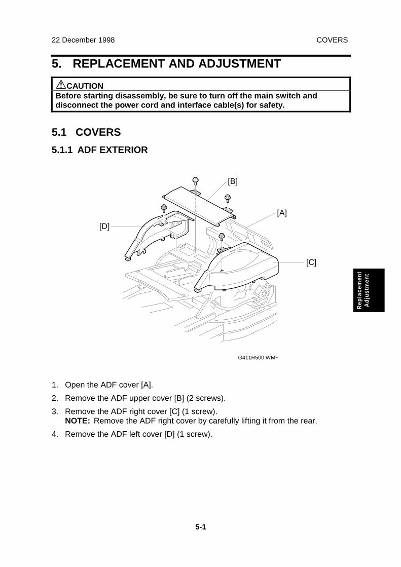
5.1.1 ADF EXTERIOR
1. Open the ADF cover [A].
2. Remove the ADF upper cover [B] (2 screws).
3. Remove the ADF right cover [C] (1 screw).NOTE: Remove the ADF right cover by carefully lifting it from the rear.
4. Remove the ADF left cover [D] (1 screw).
G411R500.WMF
[C]
[A]
[B]
[D]

COVERS 22 December 1998
5-2
5.1.2 ADF COVER
1. Remove the ADF upper and ADF right cover (see ADF Exterior).
2. Remove the rear cover (see Scanner Exterior/Operation Panel).
3. Open the platen cover vertically (see Exposure Glass).
4. Remove the spring [A].
5. Remove the pin [B] (1 screw).
6. Remove the ADF cover [C] (1 connector).
G411R502.WMF
G411R501.WMF
[C]
[B]
[A]

22 December 1998 COVERS
5-3
Rep
lace
men
tA
djus
tmen
t
5.1.3 SCANNER EXTERIOR/OPERATION PANEL
1. Remove the operation panel [A] (1 screw).
2. Remove the front cover [B] (3 screws).
3. Remove the left cover [C] (2 screws).
4. Remove the right cover [D] (2 screws).
5. Remove the rear cover [E] (3 screws).
G411R503.WMF
G411R504.WMF
[E]
[C]
[D]
[A]
[B]

ADF AND UPPER SIDE 22 December 1998
5-4
5.2 ADF AND UPPER SIDE
5.2.1 DOCUMENT SENSOR
1. Remove the ADF upper cover (see ADF Exterior).
2. Remove the document sensor [A] (1 connector, 2 screws).
5.2.2 SEPARATION UNIT
1. Remove the ADF upper, ADF left, and ADF right cover (see ADF Exterior).
2. Remove the separation unit [A] (3 connectors, 4 screws).
G411R505.WMF
G411R506.WMF
[A]
[A]

22 December 1998 ADF AND UPPER SIDE
5-5
Rep
lace
men
tA
djus
tmen
t
5.2.3 DOCUMENT TABLE ASSEMBLY
1. Remove the separation unit (See Separation Unit).
2. Remove the document table assembly [A] (3 screws).
5.2.4 CIS
1. Remove the document table assembly (See Document Table Assembly).
2. Remove the stopper bracket [A] (1 screw).
3. Remove the ADU (See ADU/Paper Transport Motor).
4. Remove the CIS [B] (2 connectors, 1 screw).
G411R507.WMF
G411R508.WMF
[A]
[B]
[A]

ADF AND UPPER SIDE 22 December 1998
5-6
5.2.5 SCANNING GUIDE PLATE
1. Remove the ADF upper, ADF left, and ADF right cover (See ADF Exterior).
2. Remove the scanning guide plate [A] (2 screws).
5.2.6 FEED SENSOR
1. Open the ADF cover [A].
2. Remove the feed cover [B] (2 screws).
3. Remove the feed sensor [C] (1 connector, 1 screw).
G411R509.WMF
G411R510.WMF
[C]
[A]
[B]
[A]
22 December 1998 ADF AND UPPER SIDE
5-7
Rep
lace
men
tA
djus
tmen
t
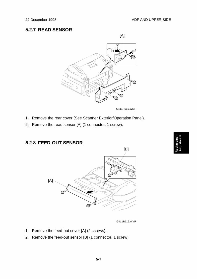
5.2.7 READ SENSOR
1. Remove the rear cover (See Scanner Exterior/Operation Panel).
2. Remove the read sensor [A] (1 connector, 1 screw).
5.2.8 FEED-OUT SENSOR
1. Remove the feed-out cover [A] (2 screws).
2. Remove the feed-out sensor [B] (1 connector, 1 screw).
G411R511.WMF
G411R512.WMF
[B]
[A]
[A]

ADF AND UPPER SIDE 22 December 1998
5-8
5.2.9 PAPER TRANSPORT DRUM
1. Remove the separation unit (see Separation Unit).
2. Remove the paper feed motor (see Paper Feed Motor).
3. Remove the ADU (see ADU/Paper Transport Motor).
4. Remove the paper transport motor (see ADU/Paper Transport Motor).
5. Remove the registration guide plate [A] (1 connector, 2 screws).
6. Remove the rear cover (see Scanner Exterior/Operation Panel).
7. Remove the stopper brackets [B] (1 screw each).
8. Remove the pins [C].
9. Open the ADF cover.
10. Remove the paper transport drum [D] (2 E-rings, 2 bearings).
G411R513.WMF
G411R514.WMF
G411R515.WMF
[A]
[B]
[D]
[C]

22 December 1998 ADF AND RIGHT SIDE
5-9
Rep
lace
men
tA
djus
tmen
t
5.3 ADF AND RIGHT SIDE
5.3.1 PAPER FEED MOTOR
1. Remove the ADF upper and ADF right cover (see ADF Exterior).
2. Remove the paper feed motor [A] (1 connector, 3 screws).
5.3.2 EDU
1. Remove the ADF upper and ADF right cover (see ADF Exterior).
2. Remove the EDU [A] (3 connectors, 2 screws).
G411R516.WMF
G411R517.WMF
[A]
[A]

ADF AND RIGHT SIDE 22 December 1998
5-10
5.3.3 ENDORSER SOLENOID
1. Remove the ADF upper and ADF right cover (see ADF Exterior).
2. Remove the endorser solenoid [A] (1 connector, 3 screws).
5.3.4 RELAY SENSOR
1. Remove the ADF upper and ADF right cover (see ADF Exterior).
2. Remove the relay sensor [A] (1 connector, 1 screw).
G411R518.WMF
G411R519.WMF
[A]
[A]
22 December 1998 ADF AND LEFT SIDE
5-11
Rep
lace
men
tA
djus
tmen
t
5.4 ADF AND LEFT SIDE
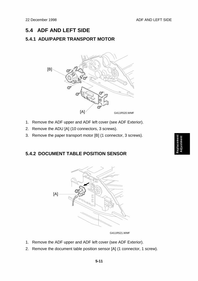
5.4.1 ADU/PAPER TRANSPORT MOTOR
1. Remove the ADF upper and ADF left cover (see ADF Exterior).
2. Remove the ADU [A] (10 connectors, 3 screws).
3. Remove the paper transport motor [B] (1 connector, 3 screws).
5.4.2 DOCUMENT TABLE POSITION SENSOR
1. Remove the ADF upper and ADF left cover (see ADF Exterior).
2. Remove the document table position sensor [A] (1 connector, 1 screw).
G411R520.WMF
G411R521.WMF
[B]
[A]
[A]

ADF AND LEFT SIDE 22 December 1998
5-12
5.4.3 PICK-UP CLUTCH/DOCUMENT TABLE LIFT CLUTCH
1. Remove the ADF upper and ADF left cover (see ADF Exterior).
2. Remove the stopper bracket [A] (2 screws).
3. Remove the pick-up clutch [B] (1 connector).
4. Remove the document table lift clutch [C] (1 connector, 1 E-ring).
G411R522.WMF
[C]
[A]
[B]

22 December 1998 SCANNER
5-13
Rep
lace
men
tA
djus
tmen
t
5.5 SCANNER
5.5.1 EXPOSURE GLASS
1. Remove the rear cover (See Scanner Exterior/Operation Panel).
2. Remove the stopper brackets [A] (2 screws).
3. Remove the pins [B].
4. Open the platen cover vertically.
5. Remove the lamp cover [C] (2 screws).
6. Remove the scale [D] (3 screws).
7. Remove the exposure glass [E].
G411R514.WMF
G411R523.WMF
[A]
[D]
[E]
[B] [C]

SCANNER 22 December 1998
5-14
5.5.2 EXPOSURE LAMP
1. Remove the exposure glass (see Exposure Glass).
2. Slide the 1st scanner to the cutout [A] in the right frame.
3. Remove the exposure lamp [B] (1 connector, 1 screw).
G411R524.WMF
[B]
[A]

22 December 1998 SCANNER
5-15
Rep
lace
men
tA
djus
tmen
t
5.5.3 SBU/LAMP STABILIZER/SCANNER MOTOR/PSU
1. Remove the exposure glass (see Exposure Glass).
2. Remove the lens cover [A] (4 screws).
3. Disconnect the flexible cable [B]
4. Remove the SBU [C] (4 screws).
5. Remove the lamp stabilizer [D] (2 connectors).
6. Remove the operation panel (see Scanner Exterior/Operation Panel).
7. Remove the front cover (see Scanner Exterior/Operation Panel).
8. Remove the scanner motor [E] (1 spring, 1 connector, 2 screws).
9. Remove the PSU [F] (5 connectors, 2 screws).
G411R525.WMFG411R526.WMF
G411R527.WMF G411R528.WMF
[A][C]
[D]
[F]
[E]
[B]

SCANNER 22 December 1998
5-16
5.5.4 IOB
1. Remove the exposure glass (see Exposure Glass).
2. Remove the lens cover (see SBU/Lamp Stabilizer/Scanner Motor/PSU).
3. Remove the PCB cover [A] (6 screws).
4. Remove the IOB [B] (5 connectors, 4 screws).
G411R529.WMF
[A]
[B]

22 December 1998 SCANNER
5-17
Rep
lace
men
tA
djus
tmen
t
5.5.5 SOP
1. Remove the operation panel and the front cover (see ScannerExterior/Operation Panel).
2. Remove the SOP (1 connector).
5.5.6 HOME POSITION SENSOR
1. Remove the right cover (see Scanner Exterior/Operation Panel).
2. Remove the home position sensor [A] (1 connector, 1 screw).
G411R538.WMF
G411R530.WMF
[A]
[A]

SCANNER 22 December 1998
5-18
5.5.7 ADF INTERLOCK SWITCH
1. Remove the rear cover (see Scanner Exterior/Operation Panel).
2. Remove the ADF interlock switch [A] (1 connector, 1 screw).
G411R531.WMF
[A]

22 December 1998 SCANNER
5-19
Rep
lace
men
tA
djus
tmen
t
5.5.8 SCANNER WIRE
1. Remove the exposure glass (see Exposure Glass).
2. Remove the stopper brackets [A] (1 screw each).
3. Remove the ADF [B] (4 connectors, 4 screws).
4. Remove the operation panel, front cover, right cover, and left cover (seeScanner Exterior/Operation Panel).
5. Remove the left frame [C] (11 screws).
6. Remove the right frame [D] (11 screws).
G411R532.WMF
G411R533.WMF
G411R534.WMF
[A]
[B]
[C]
[D]

SCANNER 22 December 1998
5-20
7. Remove the right and left scanner wire brackets [A] (1 screw each). Then,remove the 1st scanner.
8. Remove the tension spring [B].
9. Loosen the screw [C] securing the wire tension bracket [D].
10. Remove the scanner wire [E].
11. Secure the 2nd scanner with the scanner positioning tools (P/N A0069104) [F].
12. Wind the new scanner wire around the scanner drive pulley in the correctdirection, as shown (�).
13. Wind the end of the new wire with the ball as shown (�).
14. Wind the end of the new wire with the ring as shown (�, � and �).
15. Wind the new scanner wire for the other side as well.
16. Install the tension spring [B] on the wire tension bracket [D].
17. Tighten the wire tension bracket [D].
G411R536.WMF
[A]
[B]
[D][C]
[E]
[F]
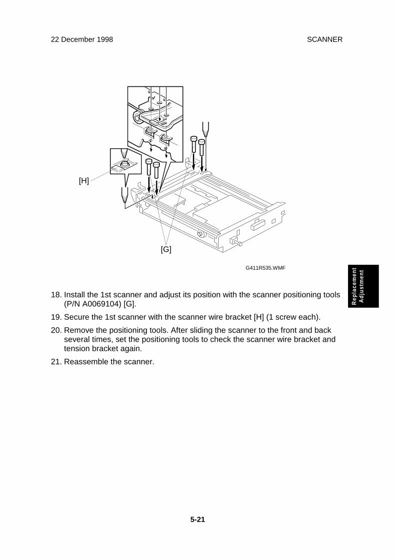
22 December 1998 SCANNER
5-21
Rep
lace
men
tA
djus
tmen
t
18. Install the 1st scanner and adjust its position with the scanner positioning tools(P/N A0069104) [G].
19. Secure the 1st scanner with the scanner wire bracket [H] (1 screw each).
20. Remove the positioning tools. After sliding the scanner to the front and backseveral times, set the positioning tools to check the scanner wire bracket andtension bracket again.
21. Reassemble the scanner.
G411R535.WMF
[H]
[G]

PCB 22 December 1998
5-22
5.6 PCB
5.6.1 SCU/RCU/IPU
1. Remove the SCU assembly [A] (2 screws).
2. Remove the RCU [B] (3 screws).
3. Remove the IPU [C] (1 screw).
NOTE: When replacing the SCU, put the old ROM (IC31) on the new SCU.
G411R537.WMF
[C]
[A]
[B]

22 December 1998 SELF-DIAGNOSTICS
6-1
Trou
ble-
shoo
ting
6. TROUBLESHOOTING
6.1 SELF-DIAGNOSTICS
The scanner automatically performs a series of self-diagnostic checks each timethe power is turned on. If an error is detected, it is displays the type of error usingthe four LEDs on the scanner. See “Detailed Section Descriptions - Initialization”for more details of the initialization procedure.
6.2 CHECK ITEMS
6.2.1 ITEMS CHECKED DURING INITIALIZATION
The self-diagnostics check the following items at power-up.1) The ADF or ADF cover is not closed properly.2) An original is jammed in the ADF.3) There is a problem with the operation of the document table.4) Memory error (system error)
Does the memory in the scanner work properly?5) Home position error (system error)
Have the scanners reached home position properly?6) Exposure lamp error (system error)
Is the standard white level detected properly?
NOTE: • If an error is detected for any of items 4) to 6), “System Error” isindicated, and the details can be checked with the self-diagnostics (seesection 6-3).
• Even if an error is detected for item 2), scanning can start in book mode.

ERROR INDICATION 22 December 1998
6-2
6.3 ERROR INDICATION
If the self-diagnostics find an error, the error is displayed by a combination of thefour LEDs on the scanner. If the dip switches on the rear of the machine are set upfor normal operation, the error is indicated roughly for users. When the dip switchesare set to the self-diagnostic mode position, the system error is indicated in detailfor technicians.
6.3.1 USER LEVEL ERROR INDICATION
LEDsConditions Contents Originals on
the table Green Green Green RedMachineInitialization
Overallmachine check On On On On
DemonstrationMode
On On On On
No On Off Off OffNormal modeYes On Off On OffNo On Off Blinking Off
Stand-by
Scan waitmode Yes On Off Blinking Off
No On On Off OffScanning Normal modeYes On On On Off
ADF cover switch open On Off Off OnDocument jam On Off Blinking OnDocument misfeed On Off On OnDocument table error On Off Blinking Blinking
User-visibleError Conditions
Endorser error Blinking Blinking On OffSystem Error Blinking Blinking Blinking Blinking
On: LED on Blinking: LED blinking Off: LED off
6.3.2 TECHNICIAN LEVEL ERROR INDICATION
LEDsError Items
Green Green Green RedMemory error (Simplex) Blinking Off Off OffMemory error (Duplex) Off Blinking Off OffExposure lamp failure Blinking Blinking On On
CIS error Blinking Blinking On BlinkingWhite level error Blinking Blinking Off Off
Home position error Blinking Blinking Blinking OnSCU error Blinking Off Off BlinkingRCU error Blinking Off On Blinking
Optional IPU error Blinking On Off Blinking
On: LED on Blinking: LED blinking Off: LED off

22 December 1998 TROUBLESHOOTING PROCEDURES
6-3
Trou
ble-
shoo
ting
6.4 TROUBLESHOOTING PROCEDURES
There are two types of troubleshooting procedure.
• For user-visible error conditions that the user could not clear up• For technician level error conditions
6.4.1 USER-VISIBLE ERROR CONDITIONS
ADF Interlock Switch Open
Symptom:
The problem cannot be solved with the procedures in the user’s manual.
Possible Causes:
• Defective ADF interlock switch• Damaged cable between the ADF interlock switch and the PSU
Procedure:
Does 24 volts come to the ADF cover interlock switch?Yes No
Is the cable damaged?Yes No
Replace the PSU.Replace the cable.
Replace the ADF interlock switch.

TROUBLESHOOTING PROCEDURES 22 December 1998
6-4
Document Jam
Symptom:
The problem cannot be solved with the procedures in the user’s manual.
Possible Causes:
• Damaged separation unit• Damaged paper transport drum assy• Damaged paper feed-out unit• Defective paper transport motor or paper feed motor• Defective read sensor or feed-out sensor• Defective SCU, IOB or ADU
Procedure:
First of all, check the sensors with demonstration and sensor check mode. SeeService Level Functions – Dip Switch Settings.
Are all the sensors OK?Yes No
Is the cable damaged?Yes No
Replace the sensor.Replace the cable.
Does the jam always happen at the same position?Yes No
Are the 24-volt lines from the PSU to the IOB (24VADU) or fromthe IOB to the ADF OK?Yes No
Is the cable damaged?Yes No
Replace the PSU.Replace the cable.
Is the 24-volt line from the ADU to the paper transport motor OK?Yes No
Is the cable damaged?Yes No
Replace the ADU.Replace the cable.
Replace the paper transport motor.NOTE: If the feed motor is defective, a “Document Table Error” is
generated.Did the jam occur at the paper transport drum assy?Yes No
Replace the paper feed-out assy.Replace the paper transport drum assy.

22 December 1998 TROUBLESHOOTING PROCEDURES
6-5
Trou
ble-
shoo
ting
Paper Misfeed
Symptom:
The problem cannot be solved with the procedures in the user's manual.
Possible Causes:
• Damaged separation unit• Defective pick-up clutch• Defective ADU• Defective SCU• Defective feed sensor
Procedure:
Does the pick-up roller mechanism work?Yes No
Is 24 volts supplied to the pick-up clutch?Yes No
Is the cable damaged?Yes No
Replace the ADU.Replace the cable.
Is there an open circuit in the clutch?Yes No
Replace the SCU.Replace the pick-up clutch.
Does the jam happen at the separation unit?Yes No
Replace the pick-up roller.Replace the separation unit.

TROUBLESHOOTING PROCEDURES 22 December 1998
6-6
Document Table Error
Symptom:
The problem cannot be solved with the procedures in the user's manual.
Possible Causes:
• Defective document table position sensor• Defective document table clutch• Defective paper feed motor• Defective ADU• Defective SCU• Damaged document table
Procedure:Is the document table itself OK?Yes No
Replace it.Does the table work (up/down operation)?Yes No
Does the separation roller mechanism work?Yes No
Does 24 volts come to the paper feed motor?Yes No
Is the cable damaged?Yes No
Replace the ADU.If the 24 volts from the PSUis defective, another errorwill be generated.
Replace the cable.Replace the motor, if it has a defective.
Does the document table lift clutch work.Yes No
Does 24 volts come to the document table lift clutch?Yes No
Is the cable damaged?Yes No
Replace the ADUReplace the cable.
Replace the document table lift clutchCheck the table lift mechanism.
Replace the SCU.NOTE: If the 5-volt line is defective, the ADF LEDs will not work, so the error type
will not be visible. Therefore it can be assumed that there is a problem witha timing signal. All timing signals are generated in the SCU and theproblem can be fixed by replacing the SCU.

22 December 1998 TROUBLESHOOTING PROCEDURES
6-7
Trou
ble-
shoo
ting
Endorser Error
Symptom:
The problem cannot be solved with the procedures in the user's manual.
Possible Causes:
• Defective endorser unit• Defective EDU
Procedure:Is the endorser unit is broken?Yes No
Is the cable between the EDU and the endorser unit or the ADUand the EDU OK?Yes No
Replace the cable.Replace the EDU.
Replace the endorser unit.

TROUBLESHOOTING PROCEDURES 22 December 1998
6-8
6.4.2 SERVICE CALL ERRORS (SYSTEM ERRORS)
If a system error occurs, the following errors can be detected with the self-diagnostics using the dip switches. See Service Level Functions – Dip SwitchSettings.
Memory Error
Symptom:
This error occurs in the following conditions.
• SRAM read/write error• DRAM read/write error• Memory over run error
Possible Cause:
• Defective SCU
Procedure:
Replace the SCU.

22 December 1998 TROUBLESHOOTING PROCEDURES
6-9
Trou
ble-
shoo
ting
Lamp Error
Symptom:
The white level cannot be adjusted.
Possible Cause:
• A mirror is out of position.• Misalignment• Defective SBU• Defective IOB• Defective SCU
Procedure:
Does the exposure lamp light during scanning?Yes No
Does 24 volts come to the lamp stabilizer?Yes No
Is the cable damaged?Yes No
Replace the PSU.Replace the cable.
Replace the exposure lampDoes the exposure lamp light?Yes No
Replace the lamp stabilizer.Go to the next step.
Are all mirrors installed properly?Yes No
Reseat any mirrors that are out of place.Does the SBU generate the correct signals?Yes No
Replace the SBU.Replace the SCU. If that does not work, try changing the IOB.
Document Table Error
Same as for the user-visible error condition. See section 6-4-1.
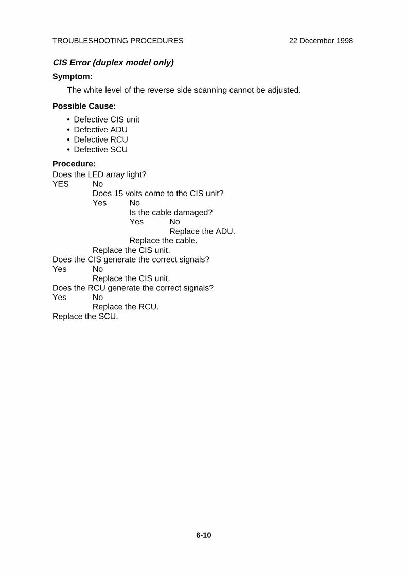
TROUBLESHOOTING PROCEDURES 22 December 1998
6-10
CIS Error (duplex model only)
Symptom:
The white level of the reverse side scanning cannot be adjusted.
Possible Cause:
• Defective CIS unit• Defective ADU• Defective RCU• Defective SCU
Procedure:Does the LED array light?YES No
Does 15 volts come to the CIS unit?Yes No
Is the cable damaged?Yes No
Replace the ADU.Replace the cable.
Replace the CIS unit.Does the CIS generate the correct signals?Yes No
Replace the CIS unit.Does the RCU generate the correct signals?Yes No
Replace the RCU.Replace the SCU.

22 December 1998 TROUBLESHOOTING PROCEDURES
6-11
Trou
ble-
shoo
ting
Shading Error
Symptoms:
A shading error occurs when one of the following conditions occurs.
• The difference in black level cannot be adjusted.• The black level cannot be adjusted.• The white level cannot be adjusted.
Possible Causes:
• A mirror is out of position.• Misalignment• Defective SCU• Defective SBU• Defective exposure lamp• Dirty white plate
Procedure:
Is there any problem with the exposure lamp?Yes No
Is the white plate dirty?Yes No
Are all the mirrors installed properly?Yes No
Reseat the mirror.Does the SBU generate the correct signals?Yes No
Replace the optical unit.Replace the SCU.
Replace the ADF exposure cover.Replace the exposure lamp.NOTE: The read signal goes to the SCU through the IOB, but the IOB does not do
any image processing. Therefore the IOB probably does not have aproblem. However, if the problem is not solved even after replacing theSCU, try changing the IOB.

TROUBLESHOOTING PROCEDURES 22 December 1998
6-12
Home Position Error
Symptom:
This error is detected when the home position sensor cannot detect the firstscanner.
Possible Causes:
• Defective scanner motor• Damaged cable between the scanner motor and the IOB• Defective IOB• Defective home position sensor• Damaged cable between the home position sensor and the IOB
Procedure:
Does the home position sensor work? Check it with sensor test mode. (See SeeService Level Functions – Dip Switch Settings.)Yes No
Does 5 volts reach the sensor?Yes No
Is the cable between the home position sensorand the IOB OK?Yes No
Replace the cable.Replace the PSU.
Replace the sensor.Is the drive wire OK?Yes No
Replace it.Does 24 volts reach the scanner motor?Yes No
Is the cable between the motor and the IOB damaged?Yes No
Replace the IOB.Replace the cable.
Replace the scanner motor.

22 December 1998 TROUBLESHOOTING PROCEDURES
6-13
Trou
ble-
shoo
ting
SCU Error
Symptom:
3.3 volts generated on the SCU failed during scanning.
Possible Cause:
• Defective SCU
Procedure:
Replace the SCU.
RCU Error
Symptom:
3.3 volts generated on the RCU failed during scanning.
Possible Cause:
• Defective RCU
Procedure:
Replace the RCU.
Optional IPU Error
Symptom:
3.3 volts generated on the optional IPU board failed during scanning.
Possible Cause:
• Defective optional IPU board
Procedure:
Replace the optional IPU board.

INDICATION WHEN A CONNECTOR IS OUT OF POSITION 22 December 1998
6-14
6.5 INDICATION WHEN A CONNECTOR IS OUT OFPOSITION
6.5.1 SCANNER
Scanner LEDsConnector
Green Green Green RedRemarks
1 (CN201) — — — —2 (CN203) On Off On Off3 (CN204) On Off Blinking Blinking Document table error4 (CN210) Blinking Blinking Blinking Blinking System error5 (CN209) — — — —6 (CN211) On Off Off On ADF interlock switch open7 (CN208) — — — —8 (CN206) Blinking Blinking Blinking Blinking System error
9 Not used Not used Not used Not used10 (CN202) Blinking Blinking Blinking Blinking System error11 (CN205) Blinking Blinking Blinking Blinking System error
On: LED on Off: LED off Blinking: LED blinking
—: When the machine is switched on, all LEDs should light briefly. However, “—” inthese tables indicates that the LED does not light up briefly at power-up.
S C U
IOB
1
2
3
56 8
7 9
11
4
10
G411T500.WMF
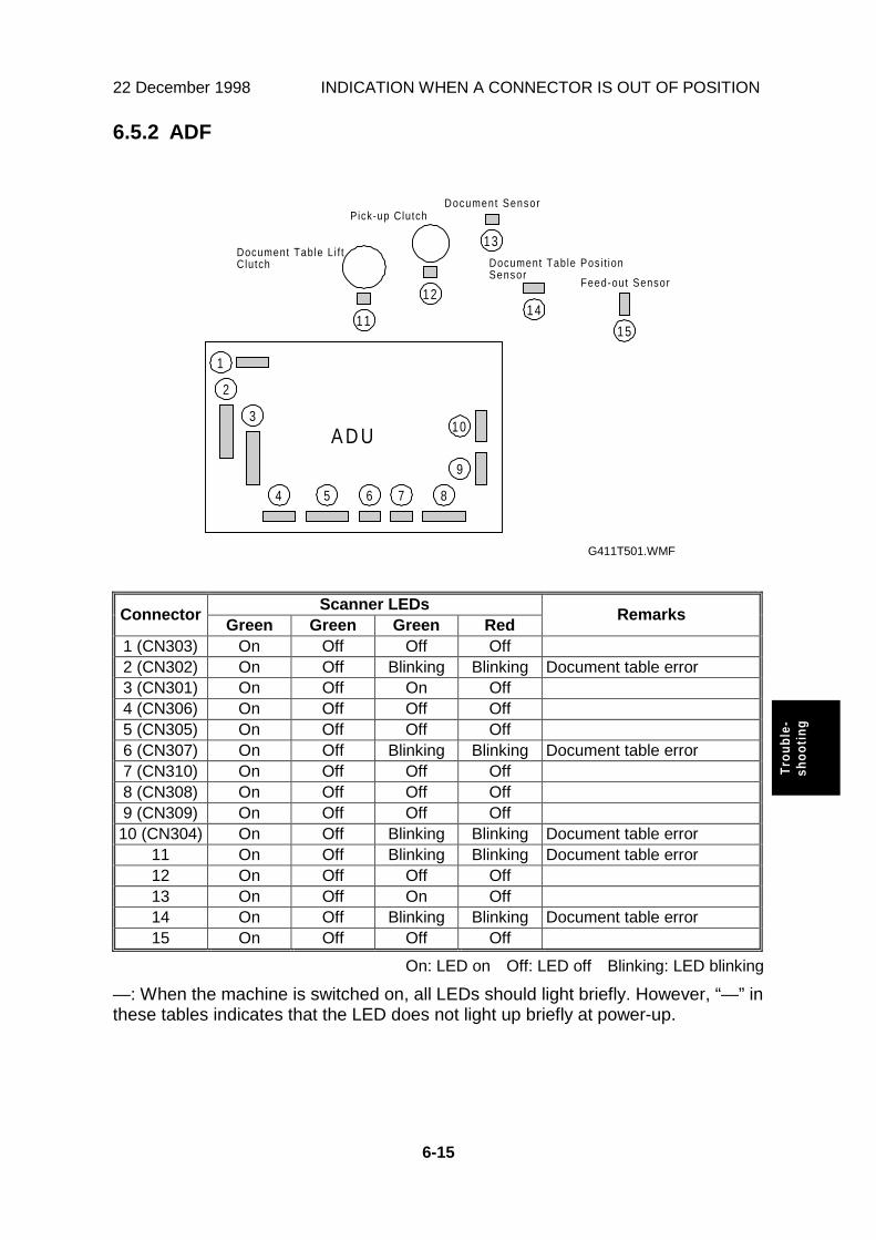
22 December 1998 INDICATION WHEN A CONNECTOR IS OUT OF POSITION
6-15
Trou
ble-
shoo
ting
6.5.2 ADF
Scanner LEDsConnector
Green Green Green RedRemarks
1 (CN303) On Off Off Off2 (CN302) On Off Blinking Blinking Document table error3 (CN301) On Off On Off4 (CN306) On Off Off Off5 (CN305) On Off Off Off6 (CN307) On Off Blinking Blinking Document table error7 (CN310) On Off Off Off8 (CN308) On Off Off Off9 (CN309) On Off Off Off10 (CN304) On Off Blinking Blinking Document table error
11 On Off Blinking Blinking Document table error12 On Off Off Off13 On Off On Off14 On Off Blinking Blinking Document table error15 On Off Off Off
On: LED on Off: LED off Blinking: LED blinking
—: When the machine is switched on, all LEDs should light briefly. However, “—” inthese tables indicates that the LED does not light up briefly at power-up.
A D U
1
2
3
5 6 87
9
11
4
10
14
15
12
13
Feed-out Sensor
Document Table Posi t ionSensor
Document SensorPick-up Clutch
Document Table L i f tClutch
G411T501.WMF

BLOWN FUSE CODITIONS 22 December 1998
6-16
6.6 BLOWN FUSE CODITIONS
Rating Symptom when turning on the main switchFuse
115 V 220 ~ 240 VPower Supply Unit
FU1 5 A/125 V 3.15 A/250 V No response.
FU31 4 A/125 VExposure lamp errorHome position errorWhite level error
FU32 4 A/125 V Document table working errorDocument jam
FU33 5 A/125 V No response.
FU35 5 A/125 V Exposure lamp errorRCU error
ADU (Duplex Model)FU101 1.25 A/250 V CIS error
EDU
FU401 3.15 A/250 V Endorser errorEndorser does not work.
Lamp StabilizerFU1 1 A/60 V Exposure lamp error
22 December 1998 IPU (IMAGE PROCESSING UNIT)
7-1
Opt
ion
7. OPTION
7.1 IPU (IMAGE PROCESSING UNIT)
7.1.1 OVERVIEW
The IPU does the following.
Dynamic Threshold
This function automatically determines a suitable threshold value based on theoriginal, and converts the scanned image to binary data.
Auto Photo/Letter
This function automatically identifies the text portions of an original and thephotographic portions, and scans each in a suitable scan mode.
Document Size Detection
This function automatically detects the width of an original, and sends theinformation to the host computer.
Section Area
This function selects an area within an original and sets scanning conditions forthat area.

IMAGE PROCESSING PATH 22 December 1998
7-2
7.2 IMAGE PROCESSING PATH
The following image processing is for the scanner with the optional IPU.
Dynamic Threshold
A suitable threshold value is determined based on the original.
Auto Photo/Letter Separation
Generally, text areas have strong contrast between the image and the background.In photo areas, mid-range gray areas are common. By using these characteristics,the original image is separated into text and photo areas.
Section Area
The original image is separated into specified areas. Each area is processed usingthe specified scanning mode.
Size Detection
See Detailed Section Descriptions – Scanner Processes.
S C U
IPUSize
Detect ionMagni f icat ion/Mir ror Process
Opt ionalIPU
Sect ionArea
Whi te /B lackconvers ion
M e m o r yControl ler
S C UOpt ional IPU
Graysca leFi l ter ing
correct ionγ
BinaryProcess ing
DynamicThresho ld
Auto Photo/Let terSparat ion
BinaryFi l ter ing
G411O500.WMF

GNDGNDGNDGND5VS5VS5VS5VS
XFESNXRSSNXSJCLXEXSNXINTCP
XSPFMXLK4
MTONXFMREF3
FMCLK2XTMRST
TMEBXTMREF3
TMMODE1XLUPSNPSUOFF
XDSETXTERR
XABORTXSTART
XSMRSTSMEB
SMMODE1SMMODE2
NCXSMREF1
GNDGND
XSSCANSOUT
XRDSYNCXCSGNDGND
XCLKCLKSBU
ADO6ADE6ADO4ADE4GNDGND
ADO2ADE2ADO0ADE0
5VE5VE5VE5VE
GNDGNDGNDGNDGNDGND5VS5VS5VE5VE
SJSNXPESN
XENDINSTXPFCLTMON
XPRASOLFMCLK1FMCLK3
XFMREF1XFMREF2
TMMODE2TMCLK
XTMREF1XTMREF2
XFANEBXJMSN
XPWONXBUSYOPRXDOPRXDSMCLK
SMCWBXSMREF2XSMREF3
OPCLKBEEPGNDGND
XSLEADSIN
XOPBSYNCSCLKGNDGND
ADO7ADE7ADO5ADE5GNDGND
ADO3ADE3ADO1ADE1
XXEONNPSN
5VE5VE5VE5VE
GNDGND
–12V–12V12V12V5VS5VS5VS5VS
SOUTXSSCAN
SINXSLEAD
XCSXRDSYNC
SCLKXOPBSYNC
GNDGND
CLKSBUGNDGNDGND
XCLKGNDGNDGND
ADE7ADO7ADE6ADO6GNDGND
ADE5ADO5ADE4ADO4GNDGND
ADE3ADO3ADE2ADO2GNDGND
ADE1ADO1ADE0ADO0GNDGND
24VSCGND
[ 24] Exposure LampGND
[ 5] H.P Sensor5VS
t
t
GND[ 5] Start
[ 5] Clear Mode[ 5] Power LED
[ 5] Busy LED[ 5] Original Detect LED
[ 5] Error LED5VE
ttt
tt
t
24VSC24VSC
[ 24] ASOU[ 24] XASOU
[ 24] BSOU[ 24] XBSOU
tt
tt
GNDOPRXDOPTXD
GNDOPCLK
–12VBEEP
5VE5VE
–12VGNDGNDGNDGND12V
24VSCGND
24VADU24VADU
GNDGNDGNDGND5VS5VS5VE5VE
GNDGNDGNDGNDGNDGNDGNDGNDGNDGNDGNDNCNCNCGNDGNDGNDGNDGNDGNDGNDGNDGNDGNDGNDDB0DB1DB2DB3DB4DB5DB6DB7DB8GNDGNDNCTERMPWRNCGNDXATNGNDXBSYXACKXRSTXMSCXSELXC/DXREDXI/D
123456789
1011121314151617181920212223242526272829303132333435363738394041424344454647484950
CN101
CN
105 1 2 3 4 5 6 7 8 9
10
11
12
13
14
15
16
17
18
19
20
21
22
23
24
25
26
27
28
29
30
31
32
33
34
35
36
37
38
39
40
41
42
43
44
45
46
47
48
49
50
51
52
53
54
55
56
57
58
59
60
61
62
63
64
65
66
67
68
69
70
71
72
73
74
75
76
77
78
79
80
CN
204 1 2 3 4 5 6 7 8 9
CN
203
A1
A2
A3
A4
A5
A6
A7
A8
A9
A10
A11
A12
A13
A14
A15
B1
B2
B3
B4
B5
B6
B7
B8
B9
B10
B11
B12
B13
B14
B15
CN
401
10 9 8 7 6 5 4 3 2 1
CN
302 1 2 3 4 5 6 7 8 9
CN
301
A15
A14
A13
A12
A11
A10
A9
A8
A7
A6
A5
A4
A3
A2
A1
B15
B14
B13
B12
B11
B10
B9
B8
B7
B6
B5
B4
B3
B2
B1
CN
308 1 2 3 4 5 6 7 8 9
10
CN103123456789
101112131415161718192021222324252627282930313233343536373839404142434445464748495051525354555657585960616263646566676869707172737475767778798081828384858687888990919293949596979899
100101102103104105106107108109110111112113114115116117118119120
CN202123456789
1011121314151617181920212223242526272829303132333435363738394041424344454647484950
CN5215049484746454443424140393837363534333231302928272625242322212019181716151413121110987654321
CN205123456
321321
CN60187654321
1
2
CN20812345678
CN206123456
123456789
CN207
CN210123456789
10
CN5123456789
10
CN42
1CN3
12
CN
8 2 1
24VADUO
24VADUO
24V
AD
UO
24V
AD
UO
AC
IN
AC
IN
CN20987654321
CN612345678
XDFOPNXFNEB
XPWDWNGNDGNDGND
CN211654321
CN7123456
CN201123456789
101112131415161718192021222324252627282930313233343536373839404142434445464748495051525354555657585960616263646566676869707172737475767778798081828384858687888990919293949596979899
100101102103104105106107108109110111112113114115116117118119120
GND[ 5] Relay Sensor5VS
24VADU24VADU[ 24] ASOUT[ 24] XASOUT[ 24] BSOUT[ 24] XBSOUT
24VADU24VADU[ 24] ASOUT[ 24] XASOUT[ 24] BSOUT[ 24] XBSOUT
s
tttt
tttt
CN30987654321
CN310123
CN303123456
CN304123456
CN287654321
CN305123456789
CN306123456
CN3071
2
3
4
CN4031
2
CN402123456789
GND15VLED
GND–12VGND12V
GND5VS
GND[ 5] Feed-out Sensor
5VSGND
[ 5] Document Table Position Sensor5VS
GND[ 5] Document Sensor
5VE
GND[ 5] Feed Sensor
5VSGND
[ 5] Read Sensor5VS
[ 24] Document Table Lift Clutch
24VADU
[ 24] Pick-up Clutch
24VADU
s
t
s
s
s
t
t
[ 24] Endorser Solenoid
24ADU
TMDNRESET
GNDSD
SET6V
MTONXENDINST
5VS
t
1 2 3 4 5 6 7 8 910
11
12
13
14
15
16
17
18
19
20
21
22
23
24
25
26
27
28
29
30
31
32
33
34
35
36
37
38
39
40
41
42
43
44
45
46
47
48
49
50
51
52
53
54
55
56
57
58
59
60
CN
106
CN701123456789
1011121314151617181920212223242526272829303132333435363738394041424344454647484950515253545556575859606162636465666768
CN104123456789
1011121314151617181920212223242526272829303132333435363738394041424344454647484950515253545556575859606162636465666768
GNDGND5VE5VEXAWKD(1)XAWKD(3)XAWKD(5)XAWKD(7)XAWFGTXALGGNDXARCLKGNDXARLSYNCXARKD(1)XARKD(3)XARKD(5)XARKD(7)GNDXCSOIPUXRESETA(1)A(3)A(5)A(7)A(9)A(11)D(9)D(11)D(13)D(15)XDIPUINSTGNDGNDGNDGND5VE5VEXAWKD(0)XAWKD(2)XAWKD(4)XAWKD(6)XAWLSYNCGNDXAWCLKGNDXARLGTXARFGTXARKD(0)XARKD(2)XARKD(4)XARKD(6)XINT OIPUXHWRXRDA(0)A(2)A(4)A(6)A(8)A(10)D(8)D(10)D(12)D(14)XC3VDTCTGNDGND
CN102
Same asCN101
CN
501 1 2 3 4 5 6 7 8 9
10
11
12
13
14
15
16
17
18
19
20
21
22
23
24
25
26
27
28
29
30
31
32
33
34
35
36
37
38
39
40
41
42
43
44
45
46
47
48
49
50
51
52
53
54
55
56
57
58
59
60
61
62
63
64
65
66
67
68
69
70
71
72
73
74
75
76
77
78
79
80
CN
502
A1
A2
A3
A4
A5
A6
A7
A8
A9
A10
A11
A12
A13
A14
A15
A16
A17
A18
A19
A20
A21
A22
A23
A24
A25
A26
A27
A28
A29
A30
A31
A32
A33
A34
B1
B2
B3
B4
B5
B6
B7
B8
B9
B10
B11
B12
B13
B14
B15
B16
B17
B18
B19
B20
B21
B22
B23
B24
B25
B26
B27
B28
B29
B30
B31
B32
B33
B34
CN
1A
1A
2A
3A
4A
5A
6A
7A
8A
9A
10
A11
A12
A13
A14
A15
A16
A17
A18
A19
A20
A21
A22
A23
A24
A25
A26
A27
A28
A29
A30
A31
A32
A33
A34
B1
B2
B3
B4
B5
B6
B7
B8
B9
B10
B11
B12
B13
B14
B15
B16
B17
B18
B19
B20
B21
B22
B23
B24
B25
B26
B27
B28
B29
B30
B31
B32
B33
B34
GN
DG
ND
SD
O7
GN
DS
DO
6G
ND
SD
O5
GN
DS
DO
4G
ND
SD
O3
GN
DS
DO
2G
ND
SD
O1
GN
DS
DO
0G
ND
SD
E7
GN
DS
DE
6G
ND
SD
E5
GN
DS
DE
4G
ND
SD
E3
GN
DS
DE
2G
ND
SD
E1
GN
DS
DE
0G
ND
SC
LK
GN
DG
ND
GN
D/L
ST
GN
DG
ND
GN
D/L
GA
TE
GN
DG
ND
SC
NG
ND
/LE
DC
GN
DG
ND
GN
DM
CO
N3
GN
DM
CO
N2
GN
DM
CO
N1
GN
DG
ND
GN
DS
2G
ND
S1
GN
DP
H2
GN
DP
H1
GN
DG
ND
GN
DX
R3V
DT
CT
OV
CLK
XO
LG
AT
ED
MA
D8
DM
AD
10
DM
AD
12
DM
AD
14
DR
EQ
XD
WR
GN
DX
CS
RC
UX
HM
RX
RE
SE
TX
HW
RN
A(0
)A
(2)
A(4
)A
(6)
A(8
)A
(10)
A(1
8)
RV
SE
LD
(8)
D(1
0)
D(1
2)
D(1
4)
GN
DM
CLK
XR
LE
DC
RM
CO
N2
RS
1R
PH
1R
SC
N1
5V
S5V
S5V
SG
ND
GN
DG
ND
GN
DX
RC
UIN
ST
XO
LS
YN
CX
OF
GA
TE
DM
AD
9D
MA
D11
DM
AD
13
DM
AD
15
XD
AC
KG
ND
XW
AIT
XIN
TR
SIB
CX
RD
RP
HIC
LK
RG
ND
A(1
)A
(3)
A(5
)A
(7)
A(9
)A
(11)
A(1
9)
WM
OD
ED
(9)
D(1
1)
D(1
3)
D(1
5)
GN
DR
SC
NR
MC
ON
1R
MC
ON
3R
S2
RP
H2
5V
S5V
S5V
S5V
SG
ND
GN
DG
ND
GN
D5V
S–12V
12V
24V
AD
U24V
AD
UG
ND
GN
DN
C
XT
MR
EF
1X
TM
RE
F2
TW
MO
DE
2X
TM
RS
TX
FM
RE
F1
XF
MR
EF
3F
MC
LK
1F
MC
LK
4M
TO
NX
SP
XE
NO
INS
TX
JM
SN
SJS
NX
FE
SN
5V
EX
RS
SN
SP
ES
NX
EX
SN
XS
JC
LX
PF
CL
XP
RA
SO
LX
INT
CP
TM
ON
FM
CLK
3F
MC
LK
2X
FM
RE
F2
TM
EB
TM
CLK
TM
MO
DE
1X
TM
RE
F2
GN
D24V
AD
UT
MC
NM
TO
NX
INT
CP
XS
PX
EN
DIN
ST
XP
RA
SO
LG
ND
5V
S
GN
DN
MU
TX
DX
NM
UIN
ST
GN
DX
WK
UP
OP
TX
DD
MA
D1
DM
AD
5D
MA
D3
NC
NC
NC
NC
NC
NC
NC
NC
XO
FG
AT
EG
ND
OV
CLK
5V
E5V
E5V
E5V
EG
ND
GN
DG
ND
GN
DN
MU
RX
DG
ND
BE
EP
OP
RX
DP
WD
WN
XP
AU
SE
DM
AD
14
DM
AD
12
DM
AD
10
DM
AD
8N
CN
CN
CN
CN
CN
CN
CN
CN
CX
OLS
YN
CX
OLG
AT
EG
ND
5V
E5V
E5V
E5V
EG
ND
GN
DG
ND
A
B
C
D
E
F
G
H
A
B
C
D
E
F
G
H
1 2 3 4 5 6 7 8 9 10 11
1 2 3 4 5 6 7 8 9 10 11
OIPUB(Option)
SCU RSCU
ADU RADU
SBU
SOP
PSU
IOB
CIS
RCU
GND
FG
GND
GND
FG
GND
GND
FG
FG
FG
F1
F31
F35
F32
F33
GND
FG Exposure Lamp
Scanner Motor
ADF InterlockSwitch
FG
SCSI I/F
SC
SII/F
5VE
15VLED
FU1
FU101
FU401
CN102.38Pin
STM3
STM2
RelaySensor
Paper TransportMotor
Paper FeedMotor
STM1
FAN
CL2
Feed-out Sensor
Document Table PositionSensor
Document Sensor
Feed Sensor
Read Sensor
Document Table Lift Clutch
Pick-up ClutchCL1
SOL1 Endorser Solenoid
EDU
Endorser
CN
35
8
CN
35
7
CN
35
7
CN
36
7
CN
35
6
CN
35
6
CN
355
CN
354
CN
354
CN
353
CN
45
1
CN
45
1
CN1
CN1
AC-OUT
AC-IN
CN
360
CN
360
CN
25
2
CN
25
5
CN
25
1
CN
362
CN
362
CN
363
CN
363
CN
361
S6
S1
S2
S3
S4
S5
CN
35
9
H.P Sensor
Lamp Stabilizer
Signal Table
AC Line
DC Line
Puls
Signal Direction
Signal Direction
Active High
Active Low
Voltage
< >
[ ]
s
t
HS2P (G407/G408/G410/G411) Point to Point Diagram