Embed Size (px)
Citation preview

Richard W, Newsome A i r Force Wright Aeronautical Laboratories
AFSC Liaison Office, NASA Langley Research Center Bampton, Virginia
James i. Thomas NASA Lanqley Research Center
Hampton, Virginia
The simulat ion of the leading-edge vortex flow about a s e r i e s of conica l d e l t a wings through solu t ion of the Navier-Stokes and Euler equations is studied. The occurrence, the v a l i d i t y , and the usefulness of separated flow solut ions t o the Euler equations a r e of p a r t i c u l a r i n t e r e s t . Central and upwind di f ference solu t ions t o t h e governing equations a r e compared f o r a series of cross-sect ional shapes, including both rounded and sharp t i p geometries.
For the rounded leading edge and t h e f l i g h t condition considered, viscous solu t ions obtained with e i t h e r c e n t r a l o r upwind di f ference methods p r e d i c t the c l a s s i c s t r u c t u r e of v o r t i c a l flow over a highly swept de l t a wing. Predicted fea tu res include the primary vortex due t o leading-edge separa t ion and the secondary vortex due t o crossflow separat ion. Central d i f ference solu t ions t o the Euler equations show a marked s e n s i t i v i t y t o g r i d refinement. On a coarse g r id , the flow separa tes due t o numerical e r r o r and a primary vortex which resembles t h a t of the viscous solu t ion is predicted. In con t ras t , t h e upwind difference solu t ions t o the Euler equations p red ic t at tached flow even f o r f i r s t -o rde r so lu t ions on coarse gr ids . On a s u f f i c i e n t l y f i n e gr id , both methods agree c lose ly and cor rec t ly p red ic t a shock-curvature-induced inv i sc id separa t ion near the leeward plane of symmetry.
Upwind di f ference solu t ions t o the Navier-Stokes and Euler equations a r e presented f o r two sharp leading-edge geometries. The viscous solu t ions a r e q u i t e s imi la r t o t h e rounded leading-edge r e s u l t s with vor t i ces of s imi la r shape and s i z e . The upwind Euler so lu t ions p red ic t at tached flow with no separa t ion f o r both geometries. However, with s u f f i c i e n t g r id refinement near t h e t i p o r through t h e use of more accurate s p a t i a l differencing, leading-edge separat ion r e s u l t s . Once the leading-edge separat ion is es tabl i shed, the upwind solu t ion agrees with recent ly published c e n t r a l d i f ference solu t ions t o the Euler equations.
INTIiODUeTION
The cur ren t i n t e r e s t i n high angle-of-attack aerodynamics and v o r t i c a l flows has focused considerable a t t e n t i o n on the numerical simulation of the flow about a swept d e l t a wing a t moderate t o high angles of a t tack . For subsonic leading edges which a r e sharp o r of small radius of curvature, t h e flow separa tes a t the t i p s and f o r m two counter-rotat ing vor t ices on opposi te s ides of t h e leeward wing surface- The presence of t h e vor t i ces produces a pressure minimum on the upper surface and r e s u l t s i n an addi t ional l i f t component not predicted by l inea r theory.
https://ntrs.nasa.gov/search.jsp?R=19860017733 2018-06-24T16:05:48+00:00Z

Interest, here, is restricted to methods whish "capture" the vortex rather than modeling it in an approximate manner. Thus, we consider only methods which solve the Euler and Navier-Stokes equations. The Havier-Stokes equations model all physical mechanisms and provide the most accurate results. Vigneron et al. solved the conical and parabolic approximations to the Navier-Stakes ewations for the vortical flow about a sharp-edged delta wing at supersonic speeds. Fujii and ~utler', solved the three-dimensional Navier-Stokes equations for the leading-edge separation about a delta wing with rounded edges at subsonic speeds. Rizzetta and Shang4 presented three- dimensional Navier-Stokes solutions for a delta wing with sharp edges at supersonic and hypersonic speeds. The principal drawbacks of the Navier- Stokes equations are the higher computational costs necessary to resolve small- scale viscous effects and the need to model turbulence in an approximate manner. However, the Navier-Stokes solutions set the standard by which less exact solutions must be judged.
In the last several years, it has been suggested that Euler codes could be the method of choice in the simulation of leading-edge vortex flows. In contrast to potential methods, the Euler equations provide the correct Rankine-Hugoniot shock jump conditions. They also admit rotational flow solutions. Indeed, numerous Euler solutions with leading-edge separation have been reported for both rounded and sharp leading edges using a variety of numerical schemes. A partial list includes the works of Rizzi et a1..6'101 Raj and Sikora, l1 and Powell, Murman et al. using a finite volume Runge- Kutta algorithm; Fujii and 0bayashi13 using a LU factored scheme whose right- hand side is identical to the Beam and Warmina scheme: and Manie et a1. l4 and
d
Newsome l using a MacCormack scheme.
Since flow separation is usually associated with generation of vorticity through the no-slip boundary condition in a viscous flow, its occurrence in an inviscid solution is of both theoretical and practical importance. Necessary conditions for flow separation include the presence of vorticity in the flow as well as an adverse pressure gradient. While the Euler equations admit rotational solutions through the transport (and for three-dimensional flow, stretching) of vorticity, there is only one valid mechanism for vorticity generation in an inviscid flow. In accord with Crocco's theorem, the Euler equations allow for the generation of vorticity through non-constant shock strength (shock curvature, shock intersection, etc. ). Salas16 first demonstrated shock-induced inviscid separation for the transonic flow about a circular cylinder. Marconi17 published similar results for the supersonic flow about circular cones and more recently elliptic cones. l8
The Euler equations are singular at a sharp tip. This, however, causes no particular problem for a finite volume scheme in which cell centered quantities are computed. Salas and ~ a ~ w i t t ' ~ ~ in considering conical flow about sharp external axial corners, have shown that a limiting form of the inviscid equations valid at the singular corner point leads to a conical analog of the isentropic Prandtl-Meyer expansion. The maximum Prandtl-Meyer expansion anqle corresponds to vacuum pressure. ~t is not clear whether theoretically valid attached flow Euler solutions exist for geometries in which the vacuum expansion limit is exceeded. For any finite radlus of curvature, the flow field is resolvable and a valid EuLer solution must approach the expansion firnit as the radius of curvature approaches zero. In a viscous gas, the flow separates well before the inviscid expansion limit is reached. Once the

saTqeyxea ~eayuoa ayq 30 uoyqanpoxquy Aq pauyeqqo aq dew suoyqenba ~eayuoa aya epauymxaqap sy uoyqnIos ayq yayym qe auqd ~eayuoa
ayq 30 uoyqeao1 ayq buyuymxaqap xaqunu sp~oudax ayq qq~m Teayuoa ATxeao~ se 30 qybnoyq aq dew MOTS ayz Oxaquxnu spxouAaa ayq uy pauyequoa sy aauapuadap aTeas
y$ua~ e 'MOT& snoasya 30a .MOT$ p~asyauy 103 qaexa ST uoyqdunsse ~ea~uoa ay& eauo ~euoysuauyp-om7 aTqeqaexq axou yanu e oquy maxqoxd Teuoysuauqp
-aaxya e buyanpax 'paqaa~bau aq uayq Leu uoyqaaxyp ~eypex ayq uy saayqenyxap y *aoe3xns ~eayuoa ayq 30 xade aqq qbnoxqq ssed yayym sdex uo aueyxenur
axe sayqyquenb MOTS TTe qeyq Aqxadoxd ayq sey ~0~3 Teayuoa y -~eayuoa aq OSTF! TI~M MOT$ buyq~nsax ayq aauys paygy~duys aq Aeu suoyqenba 6uyuxaaob ay? uayq 'saypoq Teayuoa qsed ~0~3 ayuosxadns oq paqayxqsax sy qsaxaquy 31
*sbuym abpa-buy pea^ dxeys Telaaas xog suoyqnTos xa~ns pue sayoqs-xayae~ xapysuoa oq papuaqxa xayqxn3 sy apoa puymdn ayz ebuym abpa-buy pea^ punox ayq xo3 U~AT~ sy suoyqenba sayoqs-xayhe~ pua xa~n~ ayq qqoq xo3 suoyqnyos aauaxa3gyp puymdn pup Texquao 30 uosyxeduoa paxyeqap axou e pue suoyqenba
sayoqs-xayae~ ~e~yuoa ayq oq papuaqxa sy poyqau aauaxaggyp puy~dn ayq 'xaded quasaxd ayq UI -uoyqexedas pyosynuy snoyxnds oq a~qyqdaasns ssax yanu aq 07 umoys axam O1~~~yqn~os xa~nz aauaxa33yp puymdn 'd~~i~aaax axoK Opaonpuy
d~~eayxaunu aq 07 pun03 se~ 'uoyqnTos snoasyn ayq go ayqsyxaqaexeya sy y3yyM 'suoyqenba xa~ns ayq yqym paqaypaxd xaqxoa uoyqexedas aya Spaxapysuoa
axam (auoa oyqdyx-ca) abpa buypea1 papunox e yqym Guym eqTap e qnoqe MOTS ayq xog suoyqenba sayoqs-xayae~ pue xaTw ayq oq suoTqnTos aauaxa33yp
TPX7Ua3 luayeq axe xaded syyq 30 sqxed yayym uox3 'SL axaxagax UI
*suoyqypuoa dxepunoq aoegxns 30 uoyqeoy~dde ayq dq paanpoxquy aq uea xoxxa 'd~~euya *uoysuedxa pydex 30 suoybax uy queay3yuGys sy
osxe qy qnq yooys e qe xapxo qsqj 02 sqxaaax uxaq xaqqex ayz .suoyqe~~yaso yooys ~oxquoo 03 unaq aauaxaggyp puoaas aayqdepe ue pue suoybax yqoous
UT uoyqedyssyp apyaoxd oq wxaq aauaxag3yp-yqxnoz xapxo-pxyyq e :sad67 omq 30 d~~exaua6 ale mxaq aayqedyssyp pappe ayz -suoyqenba pazyqaxosyp ayq 03 pappe
d~p~auab axe sunaq aayqedyssyp pup aayqedyssyp dT-pxnqeu qou ale sauayas aauaxa33yp TexquaD *aayqedyssyp dT-p~nqeu axe sauayas pu~~dn .poyqam ayq
go xapxo ayq pue uoyqnTosax ysau pao~ ayq uo quapuadap sy yayym uoyqeTnaTe3 ayq uy quaxayuy xaqunu sp~ou6ax aaTqaag$a ue sy axayq 'yans sy -6qyr~qeqs
xog aayqedyssyp aq qsnu 'paauaxa33yp puymdn xo Texquaa xayqaym 1myqrxo6xe Teayxamnu Auy .uorqexedas prasyauy uy q~nsax uaqjo aznqsuna so snypex ?Terns
so sbuym 103 suorqenba xapz ay3 03 suoyq.nTos Tearxaunu 'a~yqaexd ul
+(saa?zpoA dxepuoaas se qans sasnqeag sno3syn Guypn~axa) suoyqenba -xaTnz ayq Aq paqTxasap d~a~enbape snyq pue py~sjnuy
d~peyquassa axe 'saaegzns 6u~~oqyb~au qqy~ uoy33exaquT sqr .aeT tuoyqou xaqxon aqa $0 sayu=uAp aqq8paysr~qeqsa an(iq~~?qaora pays go 1aAa-C aysl puv uo~.rbe~edas

into the three-dimensional Navier-Stokes equationsr written in terms of the non-dimensional Cartesian variables (x,y,z). Upon simplifying for conical flow, the govering equations may be expressed in conservation form as
A A A
The inviscid equations are obtained by dropping the terms (G ,HV,SV). v
The general three-dimensional, upwind, Euler/thin layer Navier-Stokes code developed by Thomas 2 0 g 2 1 was specialized for conical flow. In the finite volume formulation, a single array of crossflow plane volumes was constructed such that the inflow and outflow surfaces are scaled by the conical transformation, as above. While the code uses a finite volume approach, the equations may be written in generalized coordinates as
At: each iteration, the inflow conditions are updated with the results of the A
previous iteration so that, at convergence, aQ/a( = 0, consistent with the conical flow approximation.
The inviscid and viscous flux vectors in equations ( 1 ) and (2) defined as
A A A 1 F,G,H = -
J
are

0 a T + O S T S a T x x x y x y z x z n
- 4
xx%P Y Y Y "-5 a ~ + a ~ + O S T X XZ Y YZ
Although the flux vectors can be written in a common form, they are in fact quite different as applied to equations (1) or (2). A general three- dimensional transformation between the Cartesian variables (x,y,z) and the computational variables is implied in equation (2), so that the flux terms can be defined as below:
In the finite volume formulation, expressions for the transformation derivatives and the Jacobain, J, are evaluated geometrically.
When working with the conical equations (I), it is convenient to work in terms of the conical variables, Y and Z. This allows a simpler form for the equations using the two-dimensional transformation:
Since
it is convenient to define the terms

so t h a t the flux terms in equation (3) can be defined as
1 The term, - , is absorbed into equation (1) when the Reynolds number and the
X time scale are defined with respect to the length scale, L, where L is the length from the body apex to the crossflow solution plane.
Upon nondimensionalization in terms of the freestream density, pm and sound speed, cwr the shear stress and heat flux terms are defined in tensor notation (summation convention implied) as:
The chain rule is used to evaluate derivatives with respect to (x,y,z) in terms of (n,<). When the thin layer assumption is made, only those derivatives in the direction normal to the wall ( c ) are retained in the stress and heat flux terms. Equations (1) and ( 2 ) are closed by the perfect gas equation of state and Sutherland's law for molecular viscosity. All calculations are for laminar flow only.
The conical flow equations (1 ) were solved with the Mac~ormack~~ unsplit, explicit finite-difference algorithm. Since the algorithm is well known, a detailed description is unnecessary. The method is second-order accurate in space and time and is conditionally stable. To control shock oscillations, MacCormackgsZ3 pressure damping was incorporated into the scheme. The damping term is O(AX~) except in regions of large pressure gradients where the pressure gradient switch forces the damping to O(Ax). MacCormack's scheme is also naturally dissipative due to unsymmetric differencing in the predictor and corrector steps.
Upwind solutions were obtained with the flux vector splitting algorithm * . - A
develope8 by Thomas. 2 0 The generalized fluxes P ,G, H, representing pressure and convection terms are split into forward and backward contributions according to the sign of the eigerrvalues of the Jaeobian matrices

A A A
aF/aQI ae/ag, aa/aq
and differenced accordingly. For example, the f l u x difference in the [-direction is
+ where 6- and 6 denote general backward and forward divided difference 5 5 operators respectively, in the <-direction. In reference 20, van Leer's flux vector splitting was extended to three-dimensional generalized coordinates.
A
The flux, F, as an example, is split according to the contravariant Mach number in the 5-direction, defined as M = u/c, where ; = u/I grad( 5) 1 . For supersonic flow, I.5) 2 I 5
and for subsonic flow, 1M5l < 1
If mass *
* - f' [kz(-u + 2c)/Y + mass
energy
F- A + = -h@d- J
where
it [kx(-; t 2c)/y + u] mass
f' [ky(-; 2c)/y + v] mass
f + 2
mass = tpc(M5 k 1) /4
f + energy mass
The surface area of the cell interface in the < direction is Igrad~I/~. the cell volume is 1/J, and

a r e t h e d i r e c t i o n cosines of t he c e l l i n t e r f a c e s i n t h e 6 d i r e c t i o n . The s p l i t - f l u x d i f f e r ences a r e implemented as a f l u x balance ac ros s a c e l l as ( f o r A 6 = A i l - A< = 1)
A + - The notation F (Q )i+1/2 denotes a forward flux evaluated using
the metric terms at the cell interface (i+1/2), with conserved variables
obtained by an upwind biased interpolation
where
- - A Qi = Qi+, - Qi v Qi - Qi Qi-1 5 5
Only fully upwind first or second-order accurate differencing has been used in the results that follow:
45 = 0 (f irst-order upwind)
45 = ' 1 = - I
(second-order upwind)
Differencing for the diffusion terms representing shear stress and heat transfer effects corresponds to second-order central differences in which second derivatives are treated as differences across cell interfaces of first derivative terms
where, for example, the term,
under t h e t h i n l aye r approximation, becomes,

* and is differenced in H as
v kf 1/2
where
The linearized, backward time approximation in delta form for the three- dimensional equations is given as
As described in reference 20, equation (18) is solved by streamwise relaxation (<-direction) and approximate factorization in the crossflow plane
where
a;+ A - I aF M = [-- + - - -1 JAt aQ aQ
In general, the solution is obtained by alternate forward and backward sweeping through the crossflow planes with a nonlinear update of the residual R indicated on the right side of (19). For the degenerate conical flow case, this corresponds to reinitialization of the inflow plane and update of the crossflow plane until convergence is achieved. Since the spatial implicit discretizations may be taken as first order with no loss in steady-state accuracy, the solution of equation (19) involves the solution of two block tridiagonal equations.
Initial conditions for both central and upwind difference methods consisted of freestream conditions. Boundary conditions consisted of freestream conditions on the outer boundary, reflection conditions in the crossflow symmetry plane and slip or no slip conditions on the body surface depending upon whether the viscous or inviscid equations are considered.
RESULTS
The E l o w about several different conical delta wings with a 70° wing sweep angle at a Mach nurnber of 2 and 10 degrees angle of attack was chosen
for study R thin elliptic cone, Fig. 1, with half angles, tan-' (yLE/x) =

2 0 0 , and tan*' (zCL/x) = 1.5'. was used a s a model f o r round leading edges with
small curvature radius . For sharp t i p s , a th inner conical body was defined
with a v e r t i c a l ha l f angle, tan-' (zCL/xj = 0. 75O and a t i p half angle - 1 angle given a s t a n fdz/dyfLg = f O Q . A s an extreme case, a zero thickness
f l a t d e l t a wing was a l s o considered.
Central and upwind difference so lu t ions t o the Navier-Stokes and Euler equations a re compared f o r the rounded leading-edge wing. Upwind di f ference Euler and Navier-Stokes r e s u l t s a r e then presented f o r the sharp t i p geometries.
ROUNDED LEADING m E S
Navier-Stokes Solutions
A comparison of c e n t r a l and u wind di f ference ca lcula t ions was made a t t Reynolds numbers of Re_ = 0.1 x 10 and 0.5 x 10 6. The g r i d consisted of 15 1 po in t s around and 65 points normal t o the body with an equal minimum s t e p s i z e a t the t i p , i n both d i rec t ions , As/x = .0002. This minimum s t e p s i z e i n the body normal d i r e c t i o n was relaxed t o a maximum value As/x = .0006 away from the t i p . The g r i d and an enlarged view of t h e t i p a re shown i n Fig. 2 . A t a Reynolds number of Re_ = 0.1 x lo6, t h e windward symmetry plane boundary l aye r contained 14 po in t s and the leading-edge boundary layer contained 7 points .
In general, c e n t r a l and upwind di f ference solu t ions , both second-order accura te , a re i n good agreement. A p l o t of the crossflow veloci ty f o r the c e n t r a l d i f ference solu t ion is shown i n Fig. 3 ( t h e upwind r e s u l t is nearly i d e n t i c a l ) . In t h i s and the r e s u l t s t o follow, the r a d i a l ve loci ty component has been subt rac ted out of the Cartesian crossflow components. The flow separa tes a t t h e leading edge with a l a rge primary vortex and a smaller secondary vortex. A t t he higher Reynolds number, Re_ = 0.5 x lo6, t h e secondary vortex is smaller r e l a t i v e t o the primary vortex. A comparison of pressure c o e f f i c i e n t s , Fig. 4, f o r both the c e n t r a l and upwind di f ference solu t ions , shows the suct ion peak t o be s t ronger f o r the higher Reynolds number. A t t h e higher Reynolds number, minor d i f ferences appear i n the two solu t ions i n t h e separa t ion zone, p a r t i c u l a r l y near the leading edge.
presented experimental da ta f o r the same e l l i p t i c cone with a small c i r c u l a r centerbody. To v e r i f y the viscous ca lcula t ions , the upwind scheme was appl ied t o the e l l i p t i c cone a t co ld i t ions corresponding t o t h e experimental da ta of Squire: M_ = 1.8, Re_ = 2.1 x 1 06. The pressure coe f f i c i en t is shown i n f i g u r e 5. The solu t ion i s i n reasonable agreement with the experiment. M i l l e r and del ineated seven d i f f e r e n t flow c l a s s i f i c a t i o n s according t o leading-edge normal Mach number and angle of a t t ack . The present r e s u l t s , which ind ica te a primary and secondary vortex with no crossflow shock, a r e i n agreement with Mi l l e r ' s c l a s s i f i c a t i o n .
Since some Reynolds number dependence was found i n the previous cases, a wider range of Reynolds n u d e r s were inves t iga ted with the thin-layer upv-rind Wavier-Stokes code for laminar flow. Although the g r id , Fig. 2, w a s n o t re f ined with increas ing Reynolds number, t h e r e s u l t s a r e believed t o be

generally valid. The pressure coefficient for the various Wynolds n d e r s is shown in Pig. S * The leeward suction pressure appears to approach a limit with increasing &ynolds nmber. The flow fields are similar with the exception of the lowest fieynolds number in which the secondary vortex is not present- Consistent with the experimental results of reference 26, differences with respect to Reynolds number are confined to the size and position of the vortex as well as the peak suction pressure.
-lev Solutions
The Euler solutions (for conical flow) are characterized by the presence of vortical singularities. The entire flow is weakly rotational inside the bow shock due to variable shock strength. Since streamlines terminate at one of the vortical singularities and each streamline crosses the shock at a different location, the flow at the singularities is multivalued. As a practical matter, for the present case, the bow shock is extremely weak and the entropy variation due to the bow shock is negligible*
Inviscid solutions for the central and upwind difference methods are compared on coarse and fine grids. While the two methods agree closely on fine grids, there are dramatic differences on the coarse grid.
Coarse Grid Euler
Since a prime motivation in solving the Euler equations is the desire to avoid the grid fineness necessary for viscous resolution, a coarse grid (75 x 55) was first considered. The minimum step size, As/x = 0.005, qives poor resolution at the tip as can be seen in Fig. 7. The crossflow velocities for the central difference solution are shown in Fig. 8. Corresponding crossflow Mach number and entropy contours are given in Fig. 9. Entropy is defined as
For constant total enthalpy, total pressure loss is given as
A comparison of the crossflow velocities, Figs. 4 and 8, reveals a large primary vortex of similar shape and size. Notably absent is the secondary vortex since there is no vorticity generating mechanism on the upper wing surface. A comparison of the pressure coefficient, Fig. 10, for the central difference inviscid and viscous results, shows surprising agreement with the exception of the over expansion at the leading edge. From Fig. 9, it can be seen that entropy is generated at the tip and is convected through the vortex. The entropy and vortieity at the tip are spurious since there is no valid mechanism for their generation in the EuEer equations. In the present case, the flow does not separate at the tip but at about 92% of chord on the leeward surface. The separation occurs downstream of a small shock at this psirit dividi~lg supersonic flows of opposite directions. With less accurate

boundary condit ions o r la rge values of the damping coef f i c i en t , the point of separa t ion moves c lose r t o the leading edge. In reference 15, severa l d i f f e r e n t boundary condit ions were t r i e d . The dawing coef f i c i en t was a l s o varied over its usual range of s t a b i l i t y . With minor exceptions i n the loca t ion of the separa t ion po in t , t h e r e s u l t was always t h e same - a l a rge primary separat ion vortex. It should be noted t h a t a minimm value of t h e damping coef f i c i en t was necessary t o maintain a s t a b l e so lu t ion . Computations by E. Murman (Massachusetts I n s t i t u t e of Technology, p r i v a t e communication) f o r t h i s case, on a s i m i l a r l y coarse g r i d with a f i n i t e volume Runge-Kutta scheme, a l s o re su l t ed i n a leading-edge separa t ion vortex.
A b e t t e r understanding of the separa t ion can be gained by a look a t the t r a n s i e n t development of t h e vortex. From the i n i t i a l condit ion, the flow quickly expanded about the leading edge t o a supersonic crossflow. A crossflow shock a l s o developed on the leeward surface with no separat ion evident . Concurrently, the leading-edge expansion produced large ent ropy/vor t ic i ty e r r o r s which were convected downstream t o t h e developing crossflow shock. The i n t e r a c t i o n of t h e two produced a separated region a t t h e base of the shock. The separa t ion then expanded t o form the primary vortex and the shock i s e i t h e r absent o r confined t o the vortex near the t i p a t the point of separat ion.
F i r s t - and second-order accurate upwind so lu t ions were computed on the same coarse gr id . The f i r s t - o r d e r scheme is the most d i s s i p a t i v e scheme considered and does not accurately resolve t h e de ta i l ed flow s t ruc tu re . However, a s can be seen i n Fig. 11, t h e flow remains a t tached a t the leading edge. The second-order so lu t ion is shown i n Fig. 12, and the higher accuracy now cor rec t ly p r e d i c t s the shock-induced vortex centered near the point y/x = 0.1. Crossflow Mach number and entropy p l o t s f o r t h e second-order accurate so lu t ion a r e given i n Fig. 13. The pressure c o e f f i c i e n t f o r t h e f i r s t - and second-order accurate so lu t ions is shown i n Fig. 14. A s would be expected, t h e leading-edge expansion and crossflow shock a r e b e t t e r resolved with the more accurate differencing. ~ h a k r a v a r t h y ~ ~ has a l s o solved the present case with an upwind Euler code on the same coarse g r id and found no evidence of leading-edge separat ion.
Fine Grid Euler
The g r id used i n the viscous so lu t ions , Fig. 2, was a l s o used fo r t h e inv i sc id ca lcu la t ion . The i n t e n t was t o reduce the e f f e c t of numerically induced e r ro r s through b e t t e r s p a t i a l resolu t ion of the t i p region. Second- order accurate c e n t r a l and upwind di f ference so lu t ions a r e v i r t u a l l y identical . on t h i s grid. A s can be seen i n Fig. 15, the c e n t r a l d i f ference solu t ion is now at tached a t t h e leading edge. I n both so lu t ions , a s i n the coarse g r i d upwind solu t ion , a small vortex appears downstream from the crossflow shock. The vortex is due t o shock generated v o r t i c i t y and is a v a l i d Euler so lu t ion . A p l o t of the crossf low Mach numbers, Fig. 16, shows both the crossflow shock and the shock induced wake. In Fig. 17, enlarged views of the crossfLow Mach number and entropy contours a r e given f o r the central. d i f ference solu t ion . Entropy is generated across the shock according t o t h e loca l shack s t rength . It is the entropy va r i a t ion normal t o the streamline whj-ch produces the v o r t i c i t y as requi red by Crocco's theorem and the subsequent vortex. On the f i n e g r id , the leading-edge expansion i s e s s e n t i a l l y i sen t rop ic . This can a l s o be seen i n Fig. 18 where the leading-

edge expansion is noticeably sharper than t h e upwind solu t ion on the coarse g r id . The small bump a t y/yLE = 0.3 i s due t o the expansion under the vortex.
Since boundary condition e r r o r , t runcat ion e r r o r , and added a r t i f i c i a l d i s s ipa t ion a l l go t o zero i n the l i m i t a s t h e g r id is refined, it is r a t h e r d i f f i c u l t t o a sce r t a in t h e p rec i se cause of t h e c e n t r a l d i f ference separa t ion . However, when compared with t h e upwind r e s u l t s , c e r t a i n p o s s i b i l i t i e s can be el iminated. Both schemes enforce t h e surface boundary condit ions with equivalent accuracy. Since t h e f i r s t -o rde r upwind so lu t ion has the l a r g e s t t runcat ion e r r o r and y e t remains at tached on t h e coarse gr id , the cause of the c e n t r a l d i f ference separa t ion is not j u s t a matter of inadequate numerical resolu t ion . The one d is t inguishing c h a r a c t e r i s t i c between t h e upwind and c e n t r a l d i f ference methods is the added a r t i f i c i a l d i s s ipa t ion model necessary f o r s t a b i l i t y and t o cont ro l shock o s c i l l a t i o n s . Although i n regions of smooth flow, t h e added terms a re of higher order than the t runcat ion e r r o r , i n regions of l a rge gradients , the pressure switch b u i l t i n t o t h e model causes t h e scheme t o r e v e r t t o f i r s t order . For t h i s reason, it has been widely speculated, but not proven, t h a t the a r t i f i c i a l d i s s ipa t ion model i s responsible f o r spurious i n v i s c i d separa t ion . It is i n t e r e s t i n g t o note, i n comparing entropy generation a t t h e t i p between the c e n t r a l and upwind solu t ions on the coarse g r i d (Figs. 9 and 13) , t h a t although t h e upwind value is lower (0.3) than the c e n t r a l d i f ference value (O.6), t h e terms a r e of the same order of magnitude.
SHARP LEADING KM;ES
Havier-Stokes Solutions
A th in- layer Navier-Stokes so lu t ion was computed f o r the t h i n , sharp- edged wing a t a Reynolds number, Rem = 0.1 x lo6, using the second-order accurate scheme. The g r id , Fig. 19, cons is ted of 151 x 65 po in t s with a minimum s t e p s i z e As/x = 0.0002. The crossflow v e l o c i t i e s , Fig. 20, e x h i b i t t h e same primary and secondary vor t i ces a t the same locat ions a s the rounded leading edge. Crossflow Mach contours a r e given i n Fig. 21.
PEuLer Solutions
Since the upwind code was found t o be much l e s s suscept ib le t o spurious inv i sc id separa t ion f o r rounded leading edges, i ts behavior f o r sharp leading edges was inves t iga ted . The e s s e n t i a l d i f ference is t h a t , unlike t h e rounded leading edge, t h e l o c a l behavior a t t h e sharp edge is s ingular . Both f i r s t - and second-order so lu t ions were computed on coarse and f i n e gr ids . Because of the very l a rge gradients i n the flow near t h e t i p , it was found necessary t o use f i r s t - o r d e r in te rpo la t ion (equation 13) i n the f lux ca lcu la t ions f o r some 3-4 po in t s away from and on e i t h e r s i d e of t h e t i p i n the second-order so lu t ions . This type of f l u x l imi t ing has been used ( r e f . 28) t o ensure monotone shock p r o f i l e s f o r s t rong shocks. The ca lcula t ion remains f u l l y conservative.
The coarse g r id , Fig. 2 2 , consisted of 75 x 55 points . T h e loca l t i p resolu t ion is s i g n i f i c a n t l y l e s s than t h a t of the sharp t i p viscous g r id , Fig. 19. On t h i s g r id , both f i r s t - and second-order so lu t ions are at tached a t t h e

leading edge. The second-order so lu t ion p r e d i c t s a vortex downstream of t he crossflow shock as can be seen i n Fig. 23. Crossflow Mach nu&er and entropy contours for the second-order so lu t ion a r e given i n Fig. 24. Despite the presence of Xarge entropy e r r o r s generated a t the t i p , leading-edge s q a r a t i o n does not occur. The pressure c o e f f i c i e n t , Pig. 25, i s s imi la r t o the rounded edge r e s u l t with a well-defined crossflow shock.
A zero thickness wing was considered i n order t o determine i f at tached flow solut ions could be obtained i n t h i s extreme case. Powell e t a1.I r ecen t ly presented leading-edge vortex so lu t ions f o r s i m i l a r geometries using a f i n i t e volume c e n t r a l d i f ference scheme. The g r id dimensions were the usual 151 x 65 points . However, a s seen i n Fig. 26, the l o c a l resolu t ion a t the t i p is r e l a t i v e l y coarse. The f i r s t - o r d e r so lu t ion d id not exh ib i t leading-edge separa t ion . The crossflow v e l o c i t i e s , Fig. 27, show a vortex downstream of the crossflow shock. Crossflow Mach number and entropy a r e given i n Fig. 28. The second-order so lu t ion exh ib i t s leading-edge separa t ion , a s i s evident i n Fig. 29. Both solu t ions a r e f i r s t - o r d e r accurate a t t h e leading edge. Although t h e (pseudo) t r a n s i e n t development of the two so lu t ions was not observed, it is presumed t h a t the i n t e r a c t i o n of the crossflow shock with t h e r o t a t i o n a l i t y induced a t t h e leading edge is uns table i n the more accurate ca lcula t ion . A s a consequence, the flow separa tes a t the base of the crossflow shock and the separa t ion bubble grows t o form the primary vortex. In Fig. 30, it can be seen t h a t the crossflow shock has been displaced t o a pos i t ion above the vortex near i t s inboard boundary. The pressure coe f f i - c i e n t f o r the two so lu t ions i s given i n Fig. 31. The second-order so lu t ion has been compared with the r e s u l t s obtained by K. Powell and E. Murman (Massachusetts I n s t i t u t e of Technology, p r iva te communication). Although the comparison is not shown, the two computations a r e i n c lose agreement, including the l e v e l of mini- mum pressure c o e f f i c i e n t and the ex ten t and shape of the separa t ion vortex,
Fine Grid Wnler
Upwind W l e r so lu t ions were computed f o r t h e t h i n , sharp-tipped wing using t h e f i n e r viscous g r id , Fig. 19. In con t ras t t o the previous coarse g r i d ca lcula t ions , both the f i r s t - and second-order so lu t ions a r e separated a t t h e leading edge. The f i r s t - o r d e r so lu t ion p red ic t s a very shallow vortex extending from the leading edge t o the cen te r l ine . The second-order so lu t ion p r e d i c t s the more fami l i a r separa t ion vortex. The crossflow veloci ty p l o t , Fig. 32, reveals two smaller secondary vor t i ces near the leading edge. Referencing the crossflow Mach number p l o t , Fig. 33, t h e secondary vor t i ces a r e t r igge red by a small crossflow shock embedded i n t h e vortex. These fea tu res were not found i n the viscous ca lcula t ion , Rew = 0.1 x lo6, Fig. 20. The inv i sc id ca lcu la t ion a l s o p r e d i c t s a crossflow shock above the vor tex near the inboard boundary which i s not present i n the viscous r e s u l t . A t h i n l aye r ( laminar) viscous ca lcu la t ion a t a Reynolds number of Reoo = 50 x lo6 a l s o f a i l e d t o exh ib i t the inv i sc id shock-induced secondary vor t i ces . The pressure coe f f i c i en t a t the lower Reynolds number i s compared with the viscous solu t ion i n Fig. 34.

"P861 sung f~~~~-p8 ladpa WIV =saTxqauroaa paqe~rlduoa ~euoysuaurrg-aa~q~ lam MOT& ssnoassn ay2 .&a uopqF?Tnurys TeafxaurnN :*a "aIqn)~1 pue Ifrend *E
"E86T KT~s '806T-€8 ladad WIV "~oT~PJ~~Juo~ bur~-ayeJq~ pug bur& e aog XaqXOA uoyqexedas
abpa buype~~. ayq 30 uoyqexnuys TeoyxaurnN :*d 'xaxqn~ pue !*x 'yyCn,g *Z
'8L61 A~nr 'LETT-8~ laded WIV 'sa6pa 6uypea? oruosqns dxeys yqy~ s6uy~ eq-raa xaw MOT& snoosyA oyuosxadns
30 uoy~exnote3 :*3 *s 'TTyyauueJ, pue !*A *p Iyoyyex !-a 'uoxaufiy~ -1
S33W3dS
*qsoo ~euoyqeqnduoo uy aseaxouy ~PU'@ZB~ ayq d3~7snF 03 waas pTnom suoyqn-tos buyqxnsax ayq uy douaqsysuoo
pup doexnooe uy aseaxouy ayq 'quaaa Aue u~ .xaybyy 6xqueoy3-p6ys sy poyqam qyoyldxa ue xo3 6qxeuad ay;t *uoyqezyqaxosyp auyq qyoy~duy ayq ayq ~0x3
6uysyxe suraqsds xeauyx ayq 6uyaxos pue Guyxquasse quads sy amyq n33 ayq 30 6qyxoFeu e qeyq we3 ayq sqoaT3ax axnby3 syy~ Oapoo puy~dn qyoy~du~y ayq a03
uoyqexaqy xad auyq nd3 uy aseaxouy %Z e ueyq ssax sy suoyqenba xaxn3 pT3STAUT
ayq 07 aayqqax suoyqenba sayoqs-xayae~ xadex uyyq ayq uy smxaq snoosya ayq buyqenxeaa 30 qsoo ayq 'pyx6 awes ayq ug *saoyqxoa Kxepuooas 30 aouasaxd ayq
xo aouapuadap sxaqurnu spxoud* se yons saxnqeag ~0x3 dxepuooas 6uyqoypaxd 30 a~qPde3u~ 6xxequauepunJ axe day3 'xayqxnd *douaqsysuoo 30 fiyxenb Teyquassa ayq yoex suoyqenba xaxw aay lsaoyqxoa uoyqexedas a6pa-buypeax 30 uoyqoypaxd
ayq xo3 Tapow e sv ouoyqsanb xaqqex ayq uo uaaq sey syseydua ayq Ixaded syyq UI *aoueqxoduq xeoyqosxd pue Teoyqaxoayq 30 suoyqsanb saspex s6uy~
e7xap 368~~ 6xybyy 30 sabpa buypeal ayq qnoqe ~0x3 lo3 suoyqenba xaxna ayq 20 uoyqn-ios ayq uy sauayos aouaxajgyp puy~dn pue xexquao 30 xoyneyaq ay;L
*uoyqexedas ahpa-6uypeax sqoypaxd osxe auayos pu~~dn ayq 'doexnooe yeyqeds xapxo xay6ry oq
qxosax xo quaurauygax pyx6 quayoyj3ns yqym 'xanamo~ -6uym ssauyoyyq oxaz uyyq dxaqyuy3uy ayq xo3 uaaa pue sa6pa 6uypea-c dxeys 6xaa 303 pun03 axaM suoyqnxos
xaxna ~013 payoeqqv -Tapow xeoysdyd quaqsysuoo e quasaxdax uye6e suoyqnTos snoosya aya *sayxqauoa6 a6pa-6uypeax dxeys xog paqnduoo axaM suoyqenba
xaxna pue sayoqs-xayne~ ayq oq suoyqnxos puy~dn *uoyqnxos xaxn3 py~ea e ST aseo syqq uy uoyqexedas aya *py& auy3 ay? uo uo~qexedas pyosyauy paonpuy
-yooys qoypaxd A~qoaxxoo spoyqaw yqoa *uoyqexedas ahpa-buypeax aonpoxd qou saop uoyqnxos puy~dn ayq 'spy& auyj pue asxeoo yqoq uo *sxeaddesyp xaqxoa
ayq lquauauygax pyx6 quayay3gns yqy~ 'xoxxa xeoyxaunu oq dxaxyqua anp sy rxaaamoy lxaqxoa uoyqexedas syy;t Oqxnsax snoosya ayq saxquasax yoyym xaqxon
uorqexedas Axeuyxd e sqcqpaxd uoyqnxos xa~nz aouaxa33yp Texquao ayq 'pyx6 asxeoo e uo *uoyqdyxosap MOT& quaqsysuoo e apynoxd pua susyueyoau xeoysAyd
aupnapx xpe aqTxasap suo~qvnba sayoqs-ray no^ ayq fsqTnsa2 aTpxnaDe 303 Axessaaau sy uoyqnTosax aqenbape ybnoyq~y "~34~ aas6e suoyqnxos sayoq~-rayae~ aauaraggrp purfidn pue Texquaa Qa6pa buypeax pagunox aqq ro,g *sadeys Teuorqaas
-sssxa Texaaas y$Tm s6uyn eqaap ~varuos log paquasaxd uaaq angq suorgenba saysqs-JsTn=H pue xa-pnz aqq o? suos.$nTas aauaaaggap pu~~dn PUP ~ex~ui)a
%NOIESa"r;9NO

Mzzetta, D, P.; and Snang, J. S . : Numerical Simulation of Eeading Edge Vortex Flows. A I M Paper 84-l544, June 1984.
Bitzel, S. M e ; and Schmidt, W.: Slender Wings With Eaading-Edge Vortex Separation - R Challenge for Panel-Methods and Euler Codes. AEAA Paper 83-0562, Jan. 1983.
Rizzi, A.: Damped Euler-Equation Method to Compute Transonic Flow Around Wing-Body Combinations. AIAA Journal, vol. 20, no. 10, Oct. 1982, pp. 1321-1328.
Rizzi, A.; Eriksson, L. E.; Schmidt, W.; and Hitzel, S. M.: Simulating Vortex Flows Around Wings. Aerodynamics of Vortical Type Flows in Three Dimensions, AGARD Conference Preprint No. 342, 1983.
Rizzi, A*; and Erickson, L. E.: Computation of Flow Around Wings Based on the Euler Equations. Journal of Computational Physics, vol. 148, 1984, pp. 45-71.
Rizzi, A.: Euler Solutions of Transonic Vortex Flow Around the Dillner Wing - Compared and Analyzed. AIAA Paper 84-2142, Aug. 1984.
Rizzi, A.: Modelling Vortex Flow Fields by Supercomputers With Supersize Memory. Aeronautical Journal, April 1985, pp. 149-161.
Raj, P.; and Sikora, J.: Free Vortex Flows: Recent Encounters With an Euler Code. AIAA Paper 84-0135, Jan. 1984.
Powell, K.; Murman, E.; Perez, E.; and Baron, T.: Total Pressure Loss in Vortical Solutions of the Conical Euler Equations. AIAA Paper 85-1701, July 1985.
Fujii, K.; and Obayashi, S.: Evaluation of Euler and Navier-Stokes Solutions for Leading-Edge and Shock-Induced Separations. AIAA Paper 85- 1563, July 1985.
Manie, F.; Neron, M.; and Schmitt, V.: Experimental and Computational Investigation of the Vortex Flow Over a Swept Wing. 14th Congress of the International Council of the Aeronautical Sciences, ICAS-84-2.8.1, Sept. 1984.
15. Newsome, R.: A Comparison of Euler and Navier-Stokes Equations for Supersonic Flow Over a Conical Delta Wing. AIAA Paper 85-0111, Jan. 1985.
16. Salas, M. D.: Recent Developments in Transonic Euler Flow Over a Circular Cylinder. Mathematics and Computers in Simulation, vol. 25, 1983, pp. 232-236.
17. Marconi, F.: The Spiral Singularity in the Supersonic Enviscid Flow Over a Cone. AIAA Paper 84-0135, Jan. 1984.
18. Marconi, F.: Shock Induced Vorticities on Elliptic Cones in Supersonic Flow. A I M Paper 85-0433, Jan. 9985.

19. Salas, M. B.; and Daywitt, J.: Structure sf the Gsnical Flow Field About External Axial Corners. AIAA Journal, vol. 17, no. 1, pp. 41-47, Jan. 1979.
20. Thomas, J. L.; van her, B.; and Walters, R. W.: Implicit Flux-Split Schemes for the Euler Equations. Aim Paper 85-1680, July 1985.
21. Thomas, J. L.; and Walters, R. W.: Upwind Relaxation Algorithms for the Navier-Stokes Equations. AIAA Paper 85-1501 CP, July 1985.
22. MacCormack, R. W.: Numerical Solutions of the Interactions of a Shock Wave With a Laminar Boundary Layer. Lecture Notes in Physics, vol. 59, Springer Verlag, 1970, pp. 151-163.
23. MacCormack, R. W.; and Baldwin, B. S.: A Numerical Method for Solving the Navier-Stokes Equations With Application to Shock-Boundary Layer Interactions. AIAA Paper 75-1, Jan. 1975.
24. Squire, L. C.: Leading-Edge Separation and Crossflow Shocks on Delta Wings. AIAA Journal, vol. 23, no. 9, March 1985, pp. 321-325.
25. Miller, D. S.; and Wood, R. M.: An Investigation of Wing Leading-Edge Vortices at Supersonic Speeds. AIAA Paper 83-1816, July 1983.
26. Szodruch, J.: Reynolds Number Influence o Journal, vol 16., no. 12, Dec. 1978, pp.
27. Chakravarthy, S.; and Ota, D.: Numerica puting Invicid Supersonic Flow Over Conical Delta Wings. January 1986.
28. Walters, R. W.; and Dwoyer, D. L.: An Effic Upwind/Relaxation Schemes for the Euler Equatl Paper 85- 1529- CP, July 1985.

Fig.
X
1 Elliptic cone, yLE/x = tan(20°),
Pig* 2 Fine p i d (251 x 6 5 p i n t s ) ,
Fig . 3 Crossflow velocity vectors, central difference Navier-st
Fig. 4 Pressure coefficient, central and upwind difference Navier- Stokes.
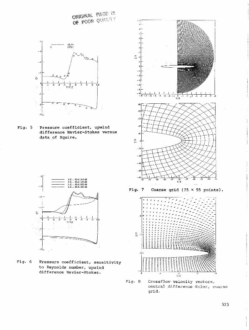
Fig.
Fig.
..--.----- SOLIN EXPER
5 Pressure coefficient, upwind difference Navier-Stokes versus data -of Squire.
---------- U.D.. RbO.O1E+06 U.0. . R&O.lOE+06
-.3 U.O.. RE=0.50E+06 U.O.. RE=5.00E+06
6 Pressure coefficient, sensitivity to Reynolds number, upwind difference Navier-Stokes.
Fig. 7 Coarse grid (75 x 55 points).
Y /X
Fig. 8 Crossflow ve loc i t y wcto r s , central difference EuPer, coarse grid.

Fig- 9 Crossflow Mach number and entropy contours, coarse grid, cen t ra l difference Euler.
Fig. 11 Crossflow velocity vectors, coarse grid, 1st-order, upwind Euler .
Fig. 12 Crossflow velocity vectors, coarse grid, 2nd-order upwind Euler .
Pig. 90 Pressure coef f i e i e n t , c e n t r a l d i f f e r e n c e coarse g r i d E u l e r versus f i n e g r i d Navier-Stokes.

Fig. Crossflow Mach number and entropy contours, coarse gr id 2nd-order upwind Euler.
Fig. 15 Crossflow velocity vectors, f i ne gr id centra l difference Euler.
Pig. 14 Pressure coefficient, coarse gr id Fig* 26 Crossflow Mach nwber , Pine g r i d , ?st- and 2nd-order ~ w i a a d W~ler. central difference mber .

Fig. 17 Crossflow Mach number and entropy contours, f i n e g r i d c e n t r a l d i f ference Euler.
---------- U.D.. 1.51 ORD
a U Fig. 19 Fine, sharp t i p , g r id (151 x
points .
Fig. 48 Pressure coefficient, f i n e q i d , central difference E a l e r versus upwind elifferenee E u L e r .

Fig. 20 Crossflow velocity vectors, fine Y / X
grid, upwind differnce Navier- Fig. 22 Coarse, sharp tip, grid (75 x 55 6
Stokes, Re = 0.1 x 10 . points ) .
Pig- 21 CrossfXoar, Mach rider, f i n e grid, Fig. 23 Crossflow vdocity v ~ c ~ o = , upwind difference Havier-Stokes, coarse grid 2nd-order , upwind
6 Re = 0 - 1 x 10 . EuHer.

Fig. 24 Crossflow Mach number and entropy contours, coarse g r id , 2nd-order, upwind Euler.
0 U.D.. IS1 ORD 0 U.D..PNDDRD
-.3
- .2
a. U
Fig. 26 Zero thickness wing g r i d ( 1 51 x 65 p o i n t s ) .
. 3 L
Fig. 29 Crsssf low velocity vectors, Fig* 25 Pressure c o e f f i c i e n t , coarse grid ze ro thickness wing,
1st- and 2nd-order upwind Euler . 1st-order upwind Euler.

-.I -.l
Y /X .3 Y/X
Fig* 28 Crossflow Mach and entropy Fig. 30 Crossflow Mach number and entropy contours, zero thickness wing, contours, zero thickness wing 1st-order upwind Euler. 2nd-order upwind Euler.
0 U.D.. 1ST ORDER 0 U.D., 2ND ORDER
-.3
-.2
-.I
Fig. 29 Crossflow ve loc i ty vec to r s , Fig. 34 Pressure coe f f i c i en t , zero zero thickness wing, thickness wing, ?st- and 2nd- 2nd-order upwind Euler. order upwind Euler.

Fig.
Fig. 32 Crossf low ve loc i ty vectors , f i n e g r id , 2nd-order, upwind Euler .
I 0
I I
1 3 U
Y /X
33 Crossflow Mach number and entropy contours, f i n e g r id , 2nd-order upwind Euler.
1st- and 2nd-order upwind Euler versus upwind Navier-Stokes
6 Re = 0 . 1 x 10 .