Embed Size (px)
Citation preview


Ricardo Jorge Guedes da Silva Nunes da Costa
An IEEE1451.0-compliant
FPGA-based
reconfigurable weblab
PhD Thesis
Information Sciences and Technologies
Supervisors
Gustavo Ribeiro Alves (IPP/ISEP/DEE)
Mário Zenha Rela (FCTUC/DEI)
Department of Informatics Engineering
Faculty of Science and Technology
University of Coimbra
January/2014


iii
Abstract Technology evolution is contributing for a sustainable change in
engineering education. New resources and tools are continuously
improving the teaching and learning processes, providing more pathways
to both students and teachers for accessing better educational contents. In
engineering courses, the experimental work, typically supported by
traditional laboratories, is also encompassing technology evolution as
denoted by the appearance of the so-called weblabs or remote
laboratories. This type of laboratories allows both students and teachers
to remotely access physical experiments enabling the control of
laboratory equipment through a simple device connected to the Internet
(e.g. a PC). Besides the provided flexibility (e.g. access to a real
laboratory on a 24x7 basis) other advantages may be enumerated, such as
the increase on students’ motivation and the cost reductions for all the
involved actors in the teaching and learning process (e.g. students,
teachers, institutions, etc.). However, current weblabs’ architectures and
their underlying infrastructures follow specific and distinct technical
implementations, i.e. there is no standard solution. Moreover, they are
not able to be reconfigured with different instruments and modules,
known as weblab modules. Whenever required in a traditional
laboratory, these modules can be attached to the target experiments,
provided that they are available in the laboratory facilities. Some
weblabs’ implementations allow setting up connections between the
target experiments and the weblab modules provided in the
infrastructure, but these modules cannot be changed or replicated, i.e. the
flexibility for changing the layout and the modules used in a particular
weblab infrastructure is very reduced. Therefore, the lack of a standard
access and design of weblabs, and the reduced flexibility for changing
the required modules for conducting the target experiments, are two
issues that are preventing their wide-spread adoption in engineering
education.
This thesis describes a research work conducted to design standard-
based reconfigurable weblabs. It analyses the possibility of using the
IEEE1451.0 Std. to design the weblabs and the modules adopted by the
underlying infrastructures to control/monitor the target experiments.
Additionally, to provide reconfiguration capability to the weblab
infrastructure, it considers the use of Field Programmable Gate Arrays
(FPGAs) for accommodating the weblab modules, thus allowing: i) the
use of standard Hardware Description Languages (HDLs) to describe the
weblab modules, making them easily sharable and replicable and; ii) the

iv
weblab infrastructures to inherit the reconfigurable nature of FPGAs,
making them flexible in order to accommodate different embedded
modules with the inherent reduction of costs that may arise from
replacing traditional with embedded instrumentation.
Besides contextualizing the role of weblabs in engineering education,
presenting some examples and commenting the use of traditional
instrumentation standards for their design, the thesis describes the
IEEE1451.0 Std., suggesting extensions for its adoption in the design of
weblabs. Supported on those suggestions and on FPGA technologies, it
specifies the development of an IEEE1451.0-compliant reconfigurable
weblab prototype and presents and analyses researchers’ opinions about
its use and the benefits for engineering education.
Keywords Remote experimentation, Weblabs, Remote laboratories, IEEE1451.0
Std., FPGAs, Hardware reconfiguration.

v
Resumo A evolução da tecnologia tem contribuído para uma mudança
sustentada na educação em engenharia. Novos recursos e ferramentas
têm melhorado os processos de ensino e aprendizagem facilitando a
alunos e professores o acesso a melhores conteúdos educativos. No caso
particular dos cursos de engenharia, o trabalho experimental, tipicamente
realizado em laboratórios tradicionais, tem sofrido alterações com base
na evolução tecnológica, de que é exemplo o aparecimento dos
denominados laboratórios remotos. Este tipo de laboratórios permite que
alunos e professores possam aceder a experiências reais controlando
remotamente o equipamento laboratorial através de um simples
dispositivo ligado à Internet (e.g. PC). Para além da flexibilidade
fornecida (acesso a um laboratório real 24 horas por dia, 7 dias por
semana) outras vantagens podem ser enumeradas, tais como a crescente
motivação dos alunos para a realização de trabalhos experimentais e a
inerente redução de custos que estes laboratórios podem trazer para todos
os actores envolvidos no processo de ensino e aprendizagem (alunos,
professores, instituições, etc.). Contudo, as atuais arquiteturas de
laboratórios remotos, bem como as infraestruturas subjacentes, seguem
implementações técnicas distintas e específicas, i.e. não existe uma
solução normalizada que suporte a reconfiguração com diferentes
instrumentos e módulos, ambos genericamente denominados por
módulos de laboratório. Quando necessário, esses módulos podem ser
interligados às experiências em teste, desde que disponíveis nas
instalações onde se encontra o laboratório. Algumas implementações de
laboratórios remotos permitem a interligação das experiências com os
módulos de laboratório disponíveis na infraestrutura subjacente.
Contudo, esses módulos não podem ser substituídos ou replicados, i.e. a
flexibilidade para modificar o layout e os módulos utilizados numa dada
infraestrutura é ainda reduzida. Neste contexto, a inexistência de um
acesso e desenvolvimento normalizados para laboratórios remotos, e a
reduzida flexibilidade para substituir/replicar os módulos necessários
para a realização de uma dada experiência, são dois aspetos que têm
dificultado a disseminação e a utilização deste tipo de laboratórios na
educação em engenharia.
Esta tese descreve o trabalho de investigação realizado com vista ao
desenvolvimento de laboratórios remotos normalizados e
reconfiguráveis. Analisa-se a possibilidade de utilizar a norma
IEEE1451.0 para o desenvolvimento de laboratórios remotos e de
módulos usados pela infraestrutura subjacente para controlar/monitorar

vi
as experiências. Adicionalmente, para fornecer capacidade de
reconfiguração à infraestrutura laboratorial, sugere-se a utilização de
dispositivos lógicos reconfiguráveis (Field Programmable Gate Arrays,
FPGAs) para suportar os módulos de laboratório, permitindo desta
forma: i) a utilização de linguagens normalizadas de descrição de
hardware (Hardware Description Languages, HDLs) para a
especificação dos módulos do laboratório, tornando-os facilmente
partilháveis e replicáveis e; ii) que a infraestrutura herde a capacidade de
reconfiguração das FPGAs, tornando-a flexível para suportar diferentes
módulos de laboratório com a inerente redução de custos que uma
solução semelhante pode trazer quando se substitui instrumentação
tradicional por embutida.
Para além de contextualizar o papel dos laboratórios remotos na
educação em engenharia, da apresentação de alguns exemplos e
comentários sobre a utilização de normas de instrumentação para a sua
especificação, a tese descreve a norma IEEE1451.0. Sugerem-se
extensões a esta norma para a sua adoção na especificação e
implementação de laboratórios remotos. Tendo por base essas sugestões
e a utilização de FPGAs, esta tese especifica o desenvolvimento de um
laboratório remoto reconfigurável e compatível com a norma
IEEE1451.0, e apresenta opiniões de investigadores sobre a sua
utilização e benefício para a educação em engenharia.
Palavras chave Experimentação remota, Laboratórios remotos, norma IEEE1451.0,
FPGAs, Reconfiguração de hardware.

vii
Acknowledgments Completing a PhD is a truly marathon that represents a conclusion stage of several
years of dedication and enthusiasm that I would not have been able to complete without
the contribution of several people and institutions.
I must first express my gratitude to my advisors; Professors Mário Rela from
UC/FCTUC and Gustavo Alves from IPP/ISEP. Their leadership, support and attention
were fundamental to achieve the proposed objectives of my work. It must be
emphasized the important contribution of Professor Gustavo Alves, since he gave me a
constant incentive to conclude the different phases of the work, and the guidance to face
the difficulties encountered during this long journey. Without disregarding other
contributions, I must truly express my gratitude to his availability for helping me and
advising me.
Over these years I have enjoyed the aid of several fellows that I would like to thanks.
In particular to the people of the LABORIS research group, that was my host place
during the PhD, in particular to André Fidalgo, Carlos Felgueiras, Manuel Gericota and
Paulo Ferreira, and to my PhD colleagues that someway helped me during my visits to
Coimbra.
At this moment I could not forget the reasons that led me to attend this PhD, in
particular my previous involvement in the area of remote laboratories during my
participation in an European project at FEUP. In this institution, I had some people that
also contributed to achieve this final result, that I would like to express my gratitude, in
particular to António Cardoso, Inês Cambeiro, Telmo Amaral, Miguel Silva and to
Professor José Martins Ferreira.
Despite all the difficulties faced during the PhD, most of them related with the
economical restrictions imposed to science in Portugal, the help of IPP/ISEP was
fundamental. Through a PROTEC program promoted by the Portuguese government,
and latter by an IPP/ISEP autonomous support, some of the expenses with academic
fees, travels and papers publications, were financed. Moreover, it was possible to reduce
the number of teaching hours at the DEE/ISEP during the first years, which gave me
more time for the PhD research activities and to conclude the courses of the first year.
During the validation & verification process, some researchers had a fundamental
contribution. I would like to express my thanks to them, namely to Unai Hernández,
Danilo Zutin, Willian Rochadel and Johan Zackrisson.
Last but not least; I would like to express my gratitude to my family and friends for
their important support, which gave me the required emotional stability to conclude this
important phase of my academic life.

viii

ix
Notes to the reader While writing an extensive document, it is usual to take decisions that aim to
facilitate the reading and understanding of its contents.
Therefore, it was decided to create a list of acronyms and abbreviations, and a
glossary with the most relevant terms and expressions found in the text. All acronyms,
and most of the abbreviations, are presented in capital letters. They are typically
specified only once, but the most relevant ones can be specified in more than one
chapter or annex. The most common in science (e.g. CD) and the majority of those
specifying names of conferences and institutions, are only defined in the acronyms and
abbreviations list.
To emphasize some terms and expressions during the thesis, the italic style was
applied. Terms written in a different font from the remaining text refer to commands or
software code.
It was also decided to put some of the information and technical descriptions into
annex. The criterion for the decisions was supported by their relevance, without hinder
the access to specific details readers may want to consult, such as implementation
details that are provided in some annexes.
Most of the references to webpages describing software applications, tools, and
specific technical information, were placed in footnotes, rather then listing them in the
reference’s section.
The DVD attached to this thesis provides some of the material referred during the
text, namely:
an introductory webpage with the list of published papers;
software packages;
the supporting webpage used during the validation & verification process
described in chapter 7;
videos exemplifying the validation & verification process;
photographs of the developed weblab;
this same thesis in a Portable Document Format (PDF).

x

xi
Contents CHAPTER 1 INTRODUCTION .......................................................................................... 1
1.1. BACKGROUND AND MOTIVATION ................................................................................................ 3 1.2. INNOVATIVE ASPECTS ................................................................................................................. 5 1.3. STRUCTURE AND ORGANIZATION ................................................................................................ 6
CHAPTER 2 WEBLABS IN ENGINEERING EDUCATION ............................................ 9
2.1. THE ROLE OF EXPERIMENTAL WORK IN ENGINEERING EDUCATION ............................................... 11 2.2. LABORATORY TYPES FOR CONDUCTING EXPERIMENTAL WORK ..................................................... 14 2.3. CONTEXTUAL ANALYSIS OF WEBLABS ......................................................................................... 17
2.3.1 Fundamentals of the Actor-Network Theory........................................................................ 18 2.3.2 Influencing contexts ........................................................................................................... 20 2.3.3 Involved actors and associations ......................................................................................... 21
2.4. PEDAGOGICAL AND TECHNICAL CONSIDERATIONS ON WEBLABS ................................................... 26
2.4.1 Meeting experimental learning goals with weblabs .............................................................. 27 2.4.2 Mapping pedagogical goals against weblabs’ capabilities .................................................... 29 2.4.3 Traditional weblab architecture ........................................................................................... 31 2.4.4 Involved technologies for implementing weblabs ................................................................ 32
2.5. WEBLAB ARCHITECTURES: A BRIEF OVERVIEW ............................................................................ 33
2.5.1 MIT iLab project ................................................................................................................ 34 2.5.2 NetLab ............................................................................................................................... 35 2.5.3 The VISIR project .............................................................................................................. 37 2.5.4 Other weblabs and projects ................................................................................................. 39
2.6. CURRENT LIMITATIONS AND PROBLEMS OF WEBLABS ................................................................... 40 2.7. SUMMARY ................................................................................................................................. 41
CHAPTER 3 CONSIDERATIONS FOR DESIGNING STANDARD AND
RECONFIGURABLE WEBLABS ............................................................. 43
3.1. WEBLAB ARCHITECTURES BASED ON INSTRUMENTATION STANDARDS .......................................... 45
3.1.1 Stand-alone and modular instrumentation ............................................................................ 45 3.1.2 Instrumentation standards ................................................................................................... 46 3.1.3 Hybrid architectures ........................................................................................................... 49 3.1.4 Embedded instrumentation.................................................................................................. 51
3.2. ON-GOING INITIATIVES FOR WEBLABS STANDARDIZATION: GOLC AND IEEEP1876 STD. .............. 53 3.3. USING AND EXTENDING THE IEEE1451.0 STD. FOR DESIGNING WEBLABS ..................................... 56
3.3.1 Overview of the IEEE1451.0 Std. ....................................................................................... 57 3.3.2 Overview of current projects and research ........................................................................... 59 3.3.3 Adopting the IEEE1451.0 Std. for weblabs ......................................................................... 60
3.4. PROVIDING RECONFIGURABILITY TO WEBLABS THROUGH FPGAS ................................................ 62
3.4.1 Infrastructure ...................................................................................................................... 62 3.4.2 Remote access .................................................................................................................... 65
3.5. SUMMARY ................................................................................................................................. 70
CHAPTER 4 THE IEEE1451.0 STD. AS A SMART FRAMEWORK FOR WEBLABS .. 73
4.1. REFERENCE MODEL: NCAP AND TIM SMART MODULES............................................................... 75 4.2. TRANSDUCER ELECTRONIC DATA SHEETS ................................................................................... 76 4.3. SMART MODULES: ACCESS AND OPERATION ................................................................................. 80
4.3.1 Addressing mechanism ....................................................................................................... 81 4.3.2 Operating states and modes ................................................................................................. 82 4.3.3 Status registers and the status-event protocol ....................................................................... 84 4.3.4 Message structures at the PHY channel ............................................................................... 85 4.3.5 Commands ......................................................................................................................... 86
4.4. THE APIS: MODULE COMMUNICATION, TRANSDUCER SERVICES AND HTTP .................................. 87

xii
4.5. SUGGESTED WEBLAB INFRASTRUCTURES COMPLIANT WITH THE IEEE1451.0 STD. ........................ 90 4.6. EXTENDING THE IEEE1451.0 STD. TO ENHANCE WEBLAB ARCHITECTURES................................... 92
4.6.1 Suggested architecture ........................................................................................................ 93 4.6.2 LabTEDS ........................................................................................................................... 94 4.6.3 Operational sequence .......................................................................................................... 97
4.7. A THIN IMPLEMENTATION OF THE IEEE1451.0 STD. APPLIED TO WEBLABS ................................... 101 4.8. SUMMARY ................................................................................................................................. 103
CHAPTER 5 A WEBLAB IMPLEMENTATION SUPPORTED BY FPGA-BASED
BOARDS ..................................................................................................... 105
5.1. OVERALL ARCHITECTURE: WEBLAB SERVER AND UNDERLYING INFRASTRUCTURE......................... 107 5.2. THE WEBLAB INFRASTRUCTURE: NCAP AND FPGA-BASED TIM ................................................. 109
5.2.1 The NCAP-TIM interface ................................................................................................... 109 5.2.2 The NCAP.......................................................................................................................... 110 5.2.3 The TIM ............................................................................................................................. 112
5.3. AN IEEE1451.0-COMPLIANT MODULE FOR BINDING WEBLAB MODULES ....................................... 113 5.4. WEBLAB ACCESSING MECHANISMS ............................................................................................. 115 5.5. THE WEBLAB RECONFIGURATION TOOL ....................................................................................... 118 5.6. SUMMARY ................................................................................................................................. 121
CHAPTER 6 THE WEBLAB RECONFIGURABLE FRAMEWORK .............................. 123
6.1. INVOLVED RESOURCES AND TOOLS ............................................................................................. 125 6.2. STRUCTURE AND FUNCTIONALITY OF THE IEEE1451.0-COMPLIANT MODULE ................................ 126
6.2.1 Decoder/Controller Module (DCM) .................................................................................... 128 6.2.2 TEDS-Module (TEDS-M) .................................................................................................. 132 6.2.3 Status/State Module (SSM) ................................................................................................. 135 6.2.4 UART Module (UART-M) ................................................................................................. 138
6.3. THE WEBLAB CONNECTING MODULES: LAYOUT AND INTERFACE ................................................... 139
6.3.1 Internal architecture ............................................................................................................ 139 6.3.2 Required Transducer Channels............................................................................................ 140 6.3.3 TC-tasks ............................................................................................................................. 143 6.3.4 Development methodology ................................................................................................. 146
6.4. THE RECONFIGURATION PROCESS ................................................................................................ 147
6.4.1 The reconfiguration sequence ............................................................................................. 148 6.4.2 The role of the configuration file ......................................................................................... 151 6.4.3 Implementation issues of the RecTool ................................................................................. 152
6.5. SUMMARY ................................................................................................................................. 155
CHAPTER 7 VALIDATION & VERIFICATION .............................................................. 157
7.1. ADOPTED STRATEGY: SCENARIO AND OBJECTIVES ....................................................................... 159 7.2. ACTORS INVOLVED: RESEARCHERS, EXPERIMENTS AND TOOLS ..................................................... 160 7.3. APPLIED METHODOLOGY ............................................................................................................ 165 7.4. REPORTED RESULTS AND CORRESPONDING ANALYSIS .................................................................. 168
7.4.1 Current weblabs’ problems ................................................................................................. 169 7.4.2 Operation of the implemented weblab ................................................................................. 170 7.4.3 Relevance of the proposed solution ..................................................................................... 174
7.5. SUMMARY ................................................................................................................................. 176
CHAPTER 8 CONCLUSIONS AND FUTURE WORK ..................................................... 179
8.1. ADOPTED ARCHITECTURE: IMPLICATIONS FOR THE EXPERIMENTAL WORK IN ENGINEERING
EDUCATION ........................................................................................................................... 181 8.2. FUTURE WORK PERSPECTIVES ..................................................................................................... 185 8.3. CONCLUDING REMARKS.............................................................................................................. 187
REFERENCES ..................................................................................................................... 189
ANNEXES ..................................................................................................................... 203
ANNEX A FPGA INTERNAL ARCHITECTURE OVERVIEW ....................................... 205

xiii
ANNEX B EXAMPLE OF AN FPGA-BASED BOARD ..................................................... 207
ANNEX C FPGA RECONFIGURATION: OPTIONS FOR WEBLABS ........................... 209
ANNEX D TEDS: EXAMPLES, ATTRIBUTES AND STATUS ........................................ 211
ANNEX E SENSORS AND ACTUATORS TRIGGER STATES ....................................... 215
ANNEX F IEEE1451.0 STATUS BITS ................................................................................ 217
ANNEX G NEW IEEE1451.0 HTTP API METHODS AND INTERFACES .................... 219
ANNEX H MAPPING IEEE1451.0 HTTP API METHODS AND COMMANDS ............. 225
ANNEX I ERROR CODES RETRIEVED FROM THE NCAP ......................................... 231
ANNEX J THE IEEE1451.0-COMPLIANT MODULE ...................................................... 233
J.1 - DCM INTERNAL REGISTERS ......................................................................................................... 233 J.2 - DCM INTERNAL AND COMMAND TASKS ........................................................................................ 235
J.2.1 - Internal tasks ....................................................................................................................... 235 J.2.2 - Command-tasks .................................................................................................................. 236
J.3 - DCM SCHEMATICS ...................................................................................................................... 240 J.4 - THE DCM-MB INTERFACE .......................................................................................................... 240 J.5 - THE DCM-MT INTERFACE ........................................................................................................... 242 J.6 - DCM REGISTERS AND BUSES FOR IMPLEMENTING THE ERROR DETECTION MECHANISM ................... 242 J.7 - ERROR CODES SPECIFIED IN THE IEEE1451.0-MODULE ................................................................. 243 J.8 - TEDS-M: SCHEMATICS AND INTERFACE ....................................................................................... 244
J.8.1 - Internal variables................................................................................................................. 244 J.8.2 - Schematics and signals ........................................................................................................ 245 J.8.3 - Handshake protocol............................................................................................................. 246 J.8.4 - Hardware API ..................................................................................................................... 246
J.9 - SSM: SCHEMATICS AND INTERFACE ............................................................................................. 248
J.9.1 - Internal variables................................................................................................................. 248 J.9.2 - Schematics and signals ........................................................................................................ 249 J.9.3 - Handshake protocol............................................................................................................. 250 J.9.4 - Hardware API ..................................................................................................................... 250
J.10 - UART-M: SCHEMATICS AND INTERFACE .................................................................................... 251
J.10.1 - Schematics and signals ...................................................................................................... 251 J.10.2 - Handshake protocol ........................................................................................................... 253
ANNEX K WEBLAB MODULES: SPECIFICATION AND DESIGN .............................. 255
K.1 - DEFINITION OF TC-TASKS ........................................................................................................... 255 K.2 - DESIGN OF TEDSS AND MTS ...................................................................................................... 255 K.3 - EXAMPLES OF WEBLAB MODULES ............................................................................................... 256
K.3.1 - Digital I/O modules ........................................................................................................... 256 K.3.2 - Step-Motor Controller Module (SMCM) ............................................................................ 260 K.3.3 - Event sensor ...................................................................................................................... 265
ANNEX L RECONFIGURATION ...................................................................................... 267
L.1 - EXAMPLES OF REPORT FILES CREATED DURING THE RECONFIGURATION PROCESS .......................... 267 L.2 - EXAMPLE OF A CONFIGURATION FILE ........................................................................................... 270 L.3 - THE RECONFIGURATION SCHEMATICS .......................................................................................... 274 L.4 - SOME EXAMPLES OF HDL FILES CREATED BY THE RECONFIGURATION PROCESS............................. 274 L.5 - EXAMPLES OF FPGA RESOURCES UTILIZATION ............................................................................ 277 L.6 - EXAMPLE OF TCL FILE CREATED DURING RECONFIGURATION....................................................... 280
ANNEX M VALIDATION & VERIFICATION ................................................................. 283
M.1 - SUPPORTING WEBPAGE: THE MAIN PAGE ..................................................................................... 283 M.2 - SCREENSHOTS OF VIDEOS EXEMPLIFYING THE INTERACTION WITH THE WEBLAB ........................... 284 M.3 - QUESTIONNAIRES PROVIDED FOR THE RESEARCHERS ................................................................... 285 M.4 - EXAMPLES OF WEBPAGES WITH THE PROVIDED METHODOLOGY ................................................... 289

xiv

xv
Figures Figure 1.1: Conceptual diagram with the thesis structure. ...................................................................... 6
Figure 2.1: Educational landscape since the 80’s. ................................................................................ 11
Figure 2.2: Theoretical and practical components of an engineering course. ......................................... 13
Figure 2.3: Preferred learning styles in engineering courses. ................................................................ 13
Figure 2.4: Laboratory types available for conducting experimental activities. ..................................... 15
Figure 2.5: Conceptual model of the Actor-Network Theory................................................................ 19
Figure 2.6: Situating RE as an actor-network....................................................................................... 20
Figure 2.7: Weblabs in the RE actor-network. ..................................................................................... 21
Figure 2.8: Pedagogical/technical issues for adopting weblabs in engineering education. ..................... 27
Figure 2.9: Division of a set of papers according to discussed weblabs pedagogical goals. ................... 30
Figure 2.10: A coarse model of a typical weblab architecture............................................................... 31
Figure 2.11: Topologies of the iLab Shared Architecture (ISA). .......................................................... 35
Figure 2.12: NetLab architecture overview. ......................................................................................... 36
Figure 2.13: NetLab web interfaces. .................................................................................................... 37
Figure 2.14: Overview of a VISIR architecture based on the PXI bus. ................................................. 38
Figure 2.15: Interfaces used in the VISIR project. ............................................................................... 39
Figure 3.1: Stand-alone and modular instrumentation. ......................................................................... 45
Figure 3.2: A layered architecture for an instrumentation system. ........................................................ 46
Figure 3.3: Example of an hybrid system applicable to weblab infrastructures. .................................... 50
Figure 3.4: Architectures for embedded instruments in weblab infrastructures. .................................... 52
Figure 3.5: Overview of the Global Online Laboratory Consortium. .................................................... 54
Figure 3.6: Current terminology and ontology defined by the GOLC. .................................................. 55
Figure 3.7: Reference model of the IEEE1451.0 Std. ........................................................................... 57
Figure 3.8: FPGA-based reconfigurable weblab infrastructure. ............................................................ 64
Figure 3.9: Architectures for embedding weblab modules in FPGA-based boards. ............................... 64
Figure 3.10: Proposed weblab architecture using FPGA-based weblabs. .............................................. 65
Figure 3.11: Hybrid solution for remote accessing weblab infrastructures. ........................................... 66
Figure 3.12: SoC solution for remote accessing weblab infrastructures. ............................................... 67
Figure 4.1: Reference model of the IEEE1451.0 Std. ........................................................................... 75
Figure 4.2: Mandatory TEDSs in an IEEE1451.0 compatible device. ................................................... 77
Figure 4.3: Diagram illustrating the group of TEDSs defined in the IEEE1451.0 Std. ........................... 79
Figure 4.4: Structure and identification header defined for all TEDSs. ................................................. 79
Figure 4.5: Addressing mechanism used by the IEEE1451.0 Std. ......................................................... 81

xvi
Figure 4.6: TIM and TC operating states. ............................................................................................ 82
Figure 4.7: Conceptual diagram of the TIM operation modes. .............................................................. 83
Figure 4.8: Status message generation logic and TIM SR generation.................................................... 85
Figure 4.9: Message structures. ........................................................................................................... 85
Figure 4.10: IEEE1451.0 Std. API layered structure and the HTTP schematic access. .......................... 88
Figure 4.11: Adopting the IEEE1451.0 Std. for designing a weblab infrastructure. ............................... 90
Figure 4.12: Possible weblab infrastructures based on the IEEE1451.0 Std. ......................................... 91
Figure 4.13: Suggested weblab architecture based on the IEEE1451.0 Std. .......................................... 94
Figure 4.14: Lab2go Metadata - Reference Model Specification. ......................................................... 95
Figure 4.15: Operational sequence for accessing weblab infrastructures. .............................................. 97
Figure 4.16: Process for registering/unregistering weblab infrastructures. ............................................ 98
Figure 4.17: Using the NCAPDiscovery and ReadLabTEDS methods to access registered weblab
infrastructures. ................................................................................................................. 99
Figure 4.18: Using the WriteTIM and ReadTIM for reconfiguring weblab infrastructures and the
suggested XML schema for the log file. .......................................................................... 101
Figure 4.19: A thin implementation of the IEEE1451.0 Std. layered structure. ................................... 102
Figure 5.1: Bock diagrams of the implemented weblab architecture. .................................................. 108
Figure 5.2: Picture of the implemented weblab architecture. .............................................................. 108
Figure 5.3: Designed weblab infrastructure based on the IEEE1451.0 NCAP-TIM reference model. .. 109
Figure 5.4: Photograph of the NCAP implemented using a thin-client computer. ............................... 111
Figure 5.5: NCAP-package folder organization. ................................................................................ 111
Figure 5.6: Picture of the FPGA-based board where the TIM is implemented..................................... 113
Figure 5.7: Overview of the IEEE1451.0-compliant module (IEEE1451.0-Module). .......................... 114
Figure 5.8: NCAP-TIM accessing mechanism. .................................................................................. 115
Figure 5.9: Example of commands sent to the TIM reconfigured with an I/O weblab module using the
Comm Operator Pal serial port tool. ................................................................................ 116
Figure 5.10: Example of a ReadTEDS command and the associated reply in XML format issued using
the IEEE1451.0-HTTP API. ........................................................................................... 117
Figure 5.11: Web interface of the weblab reconfiguration tool. .......................................................... 119
Figure 6.1: Conceptual diagram with tools, resources and the human actors involved in the
reconfiguration process. ................................................................................................. 125
Figure 6.2: Internal modules of the IEEE1451.0-Module. .................................................................. 127
Figure 6.3: MT structure and an example with 3 TCs. ....................................................................... 130
Figure 6.4: Implemented logic for the status-event protocol. .............................................................. 131
Figure 6.5: Adopted architecture to handle events generated by weblab modules. .............................. 132
Figure 6.6: The TEDS-M architecture and the data structure of a TEDS. ........................................... 133

xvii
Figure 6.7: Layered structure supported by the Access_ModTEDS hardware API to access the TEDSs
memories reconfigured in the TEDS-M. ......................................................................... 134
Figure 6.8: The SSM architecture and the status/state memories structures......................................... 135
Figure 6.9: Implemented logic for the condition registers and for the SR signal. ................................ 137
Figure 6.10: Layered structure supported by the Access_ModStatusState hardware API to access the
SSM status and the state memories. ................................................................................ 137
Figure 6.11: The architecture of the UART-M and the interface with the remaining modules of the
IEEE1451.0-Module. ..................................................................................................... 138
Figure 6.12: Parts required for defining a weblab module compatible with the IEEE1451.0-Module. . 139
Figure 6.13: Data flow between the DCM and the weblab modules.................................................... 140
Figure 6.14: Possibilities for controlling weblab modules parameters using TCs. ............................... 141
Figure 6.15: Control of a daisy chain bus with the modules connected to the IEEE1451.0-Module. .... 142
Figure 6.16: Association between IEEE1451.0 commands and TC-tasks............................................ 143
Figure 6.17: Operational sequences performed by the TC-tasks. ........................................................ 145
Figure 6.18: Methodology for designing weblab modules compatible with the IEEE1451.0-Module. . 146
Figure 6.19: The RecTool interface panels and files used for reconfiguring the weblab infrastructure. 147
Figure 6.20: The complete reconfiguration sequence using the RecTool. ........................................... 149
Figure 6.21: Role of the software modules running in the RecTool and connections established within
the TIM. ......................................................................................................................... 151
Figure 6.22: Weblab server internal modules and the actions used for creating the weblab project that
reconfigures the TIM. ..................................................................................................... 153
Figure 7.1: Scenario adopted to validate and verify the implemented weblab. .................................... 160
Figure 7.2: Involved researchers in the validation & verification process. .......................................... 161
Figure 7.3: Configurations defined to the weblab infrastructure. ........................................................ 162
Figure 7.4: Adopted TEDSs in each configuration. ............................................................................ 163
Figure 7.5: Screenshots of the supporting webpage and videos provided to guide researchers during the
validation & verification process. ................................................................................... 163
Figure 7.6: Typical interface adopted for issuing IEEE1451.0 commands using the IEEE1451.0-HTTP
API. ............................................................................................................................... 165
Figure 7.7: Phases adopted for the researchers’ interaction with the weblab. ...................................... 165
Figure 7.8: Picture of the adopted step-motor and video frame of its axis provided by the supporting
webpage. ........................................................................................................................ 166
Figure 7.9: Command sequence applied to control the step-motor rotation in the 1st configuration. ..... 167
Figure 7.10: Graph results with the accordance with six problems currently faced by weblabs. .......... 169
Figure 7.11: Graph results with the accordance with the configuration phases. ................................... 171
Figure 7.12: Graph results with the accordance with the verify configuration phases. ......................... 172
Figure 7.13: Graph results with the accordance with the weblab modules’ control.............................. 174
Figure 7.14: Graph results with the accordance with the proposed weblab.......................................... 175
xviii
Figure 8.1: Suggested sequence for the engineering practical work in distance learning. .................... 181
Figure 8.2: Screenshots of a tool being developed to facilitate the design of TEDSs, map and
configuration files adopted during the reconfiguration process. ....................................... 186
Figure A.1: Structural elements of an FPGA. .................................................................................... 205
Figure B.1: Example of an FPGA-based board from Xilinx (Spartan 3E). .......................................... 207
Figure C.1: Possibilities for reconfiguring an FPGA with different weblab modules........................... 209
Figure E.1: Sensor trigger states. ....................................................................................................... 215
Figure E.2: Actuator trigger states. .................................................................................................... 215
Figure E.3: Information notes for the trigger state diagrams. .............................................................. 216
Figure J.1: DCM schematics with all adopted buses for interfacing the other modules........................ 240
Figure J.2: Illustration of the adopted registers to handle errors.......................................................... 243
Figure J.3: TEDS-M internal schematics. .......................................................................................... 245
Figure J.4: Handshake protocol adopted for the DCM-TEDS-M interface. ......................................... 246
Figure J.5: SSM internal schematics. ................................................................................................. 249
Figure J.6: Handshake protocol for the DCM-SSM interface. ............................................................ 250
Figure J.7: Modules of the UART-M and its buses and lines. ............................................................. 252
Figure J.8: Handshake protocol used to read data from the Rx module. .............................................. 253
Figure J.9: Handshake protocol used to fill-in the buffer_out_tx and to transmit data to the NCAP. .... 254
Figure K.1: Freeware hexadecimal editor XVI32 used to define TEDSs and MTs. ............................. 256
Figure K.2: Digital I/Os weblab modules connected to the IEEE1451.0-Module. ............................... 257
Figure K.3: Buses, lines and the handshake protocol of the I/O weblab modules. ............................... 257
Figure K.4: Sequence of commands issued to the I/O digital weblab modules. ................................... 259
Figure K.5: Commands issued to validate the I/O digital weblab modules. ......................................... 259
Figure K.6: SMCM connected to the IEEE1451.0-Module. ............................................................... 260
Figure K.7: Handshake protocol used to access the SMCM through the TC-tasks. ............................. 262
Figure K.8: The SCMC HDL modules and buses. ............................................................................. 263
Figure K.9: Sequence of commands adopted for validating the SMCM. ............................................. 264
Figure K.10: IEEE1451.0 commands issued to validate the SMCM. .................................................. 265
Figure K.11: Event Sensor connected to the IEEE1451.0-Module. ..................................................... 265
Figure K.12: TIM-initiated message retrieved from the ES after detecting an event. ........................... 266
Figure L.1: Reconfiguration schematics. ........................................................................................... 274
Figure M.1: Screenshots of the supporting webpage front panels. ...................................................... 283
Figure M.2: Videos exemplifying the interaction with the weblab. ..................................................... 284
Figure M.3: Table grid provided in the supporting webpage with the different stages of the adopted
methodology in the validation and reconfiguration process.............................................. 289
Figure M.4: Examples of webpages used during the validation and verification process. .................... 290

xix
Tables Table 2.1: Some concepts associated to E-learning. ............................................................................. 12
Table 2.2: A personal comparison among laboratory types. ................................................................. 17
Table 2.3: Human actors in Remote Experimentation. ......................................................................... 22
Table 2.4: Non-human actors in Remote Experimentation. .................................................................. 22
Table 2.5: Associations among human actors in the RE actor-network. ................................................ 23
Table 2.6: Associations among technical actors in the RE actor-network. ............................................ 24
Table 2.7: Associations between technical and human actors in the RE actor-network. ........................ 25
Table 2.8: Experimental learning goals with weblabs. ......................................................................... 27
Table 2.9: Weblabs’ repositories, projects and consortiums. ................................................................ 40
Table 3.1: Overview of some well known instrumentation bus standards. ............................................ 47
Table 3.2: The IEEE1451.x Std. family. .............................................................................................. 58
Table 3.3: A selection of commercial MWS. ....................................................................................... 67
Table 3.4: A selection of TCP/IP cores. ............................................................................................... 68
Table 3.5: Considerations about the number of FPGAs versus the weblab modules required for
implementing a reconfigurable infrastructure based on an hybrid architecture.................... 69
Table 4.1: IEEE1451.0 main TC sampling modes and complemented modes. ...................................... 83
Table 4.2: IEEE1451.0 TIM to NCAP transmission modes. ................................................................. 84
Table 4.3: Classes of standard commands............................................................................................ 87
Table 4.4: IEEE1451.0 Std. HTTP API (paths and methods). .............................................................. 89
Table 4.5: LabTEDS fields. ................................................................................................................ 96
Table 4.6: Mapping of HTTP APIs’ methods to TIM commands. ...................................................... 102
Table 6.1: Implemented commands to access the TEDS-M. ............................................................... 133
Table 6.2: Memory selection in the TEDS-M. ................................................................................... 133
Table 6.3: Instructions provided by the Access_ModTEDS hardware API. ......................................... 134
Table 6.4: Implemented commands to access the SSM. ..................................................................... 136
Table 6.5: Instructions provided by the Access_ModStatusState hardware API................................... 137
Table 7.1: Accordance with six problems currently faced by weblabs. ............................................... 169
Table 7.2: Accordance with the configuration phases. ....................................................................... 171
Table 7.3: Accordance with the verify configuration phases. ............................................................. 172
Table 7.4: Accordance with the weblab modules’ control. ................................................................. 173
Table 7.5: Accordance with the proposed weblab. ............................................................................. 175
Table C.1: Options for reconfiguring FPGAs. ................................................................................... 210
Table D.1: Meta-TEDS structure....................................................................................................... 211
xx
Table D.2: TC-TEDS structure.......................................................................................................... 212
Table D.3: TEDS’ attributes implemented in an octet. ....................................................................... 213
Table D.4: TEDS’ status implemented in an octet.............................................................................. 213
Table F.1: Status bits defined by the IEEE1451.0 Std. ....................................................................... 217
Table G.1: NCAPRegister method. ................................................................................................... 219
Table G.2: NCAPDiscovery method. ................................................................................................ 220
Table G.3: ReadLabTEDS method. ................................................................................................... 220
Table G.4: WriteLabTEDS method. .................................................................................................. 221
Table G.5: ReadTIM method. ........................................................................................................... 221
Table G.6: WriteTIM method. .......................................................................................................... 222
Table G.7: ReadLog method. ............................................................................................................ 222
Table G.8: WriteLog method. ........................................................................................................... 223
Table H.1: Mapping the ReadData method to SamplingMode and ReadTCDSsegment commands. .... 225
Table H.2: Mapping the StartReadData and MeasurementUpdate methods to SamplingMode and
ReadTCDSsegment commands. ...................................................................................... 226
Table H.3: Mapping the WriteData method to SamplingMode and WriteTCDSsegment commands. .. 226
Table H.4: Mapping the StartWriteData method to SamplingMode and WriteTCDSs commands. ...... 227
Table H.5: Mapping the ReadTEDS and ReadRawTEDS methods to the ReadTEDSsegment
command. ...................................................................................................................... 227
Table H.6: Mapping the UpdateTEDSCache to the ReadTEDSsegment command. ............................ 228
Table H.7: Mapping the WriteTEDS and WriteRawTEDS methods to the WriteTEDSsegment
command. ...................................................................................................................... 228
Table H.8: Mapping the SendCommand method. .............................................................................. 229
Table H.9: Mapping the StartCommand and CommandComplete methods......................................... 229
Table H.10: Mapping the Trigger and the StartTrigger methods to commands ReadTEDSsegment,
SamplingMode and TriggerCommand. ........................................................................... 229
Table I.1: Error source codes. ........................................................................................................... 231
Table I.2: Error enumeration codes. .................................................................................................. 231
Table J.1: List with the DCM internal registers.................................................................................. 233
Table J.2: DCM internal-tasks........................................................................................................... 235
Table J.3: Commands common to the TIM and to each TC (ClassID=1). ........................................... 236
Table J.4: Transducer operating state commands (ClassID=3). .......................................................... 238
Table J.5: Transducer either idle or operating state commands (ClassID=4). ...................................... 239
Table J.6: TIM any state commands (ClassID=7). ............................................................................. 239
Table J.7: MB definition (pieces of code in *.conf and definitions_GENERIC.vh files). ..................... 241
Table J.8: Buses and lines adopted for the DCM-MB interface. ......................................................... 241

xxi
Table J.9: Sequence for accessing to the MB (Verilog code examples)............................................... 241
Table J.10: Buses and lines adopted for the DCM-MT interface......................................................... 242
Table J.11: Sequence for reading the MT (Verilog code example). .................................................... 242
Table J.12: Error codes mapped from the condition register to the error_reg. ................................. 243
Table J.13: Example of a definitions_TEDS.vh file automatically created during the reconfiguration
process. .......................................................................................................................... 244
Table J.14: Buses and lines adopted for the DCM-TEDS-M interface. ............................................... 245
Table J.15: TEDS-M hardware API instructions (available in file: Access_ModTEDS.vh). ................. 247
Table J.16: Sequences for accessing the TEDS-M hardware API instructions..................................... 248
Table J.17: Example of a definitions_GENERIC.vh file automatically created during the
reconfiguration process. ................................................................................................. 248
Table J.18: Buses and lines adopted for the DCM-SSM interface....................................................... 249
Table J.19: SSM hardware API instructions (available in the file: ModStatusState.vh). ...................... 250
Table J.20: Sequences for accessing the SSM hardware API instructions. .......................................... 251
Table J.21: Signals used by the Rx module (data reception from the NCAP). ..................................... 252
Table J.22: Signals used by the Tx module (data transmission to the NCAP). .................................... 252
Table K.1: Example of Verilog HDL code for implementing TC-tasks using the mandatory
end_tc_task and attending_event variables. ............................................................. 255
Table K.2: TC-TEDS relevant fields defined to control the 8-Bit Input Module. ................................ 257
Table K.3: TC-TEDS relevant fields defined to control the 6-Bit Output Module. .............................. 258
Table K.4: TC-TEDS relevant fields defined to control the SMCM. .................................................. 261
Table K.5: MD-TEDS defined fields to control the SMCM. .............................................................. 261
Table K.6: Internal SMCM access codes. .......................................................................................... 262
Table K.7: Internal modules of the SMCM and their features. ........................................................... 263
Table K.8: Defined TC-TEDS relevant fields to control the event sensor. .......................................... 266
Table L.1: Report generated by the Bind software module. ................................................................ 267
Table L.2: Report generated by the Config software module. ............................................................. 268
Table L.3: Report generated by the ISE Webpack in the synthesis operation. ..................................... 268
Table L.4: Report generated in the reconfiguration operation using the iMPACT tool. ....................... 269
Table L.5: Report generated by the UrJTAG tool after sending the weblab project to the FPGA-based
board.............................................................................................................................. 270
Table L.6: Example of a configuration file used in the reconfiguration process. ................................. 270
Table L.7: Example of Verilog HDL files with generic definitions..................................................... 275
Table L.8: Example of Verilog HDL files defining the DCM-weblab modules interfaces. .................. 275
Table L.9: Example of files used to define the TEDSs memories. ...................................................... 276
Table L.10: Example of files used to define the MT. ......................................................................... 277
xxii
Table L.11: Some definitions made in the ISE Webpack for creating the weblab project. ................... 278
Table L.12: FPGA resources used by the IEEE1451.0-Module in two configurations. ........................ 278
Table L.13: Number of FPGA resources used by the weblab modules................................................ 279
Table L.14: Overview of FPGA resources percent usage in both configurations. ................................ 279
Table L.15: Example of a TCL file created by the RecTool with instructions for synthesizing the
weblab project................................................................................................................ 280

xxiii
Acronyms and abbreviations 2D Two Dimensional
3D Three Dimensional
A/D Analog-to-Digital
ABET Accreditation Board for Engineering and Technology
ACM Association for Computing Machinery
AMS Analog and Mixed Signal
ANT Actor-Network Theory
API Application Program Interface
ASCII American Standard Code for Information Interchange
ASEE American Society for Engineering Education
ASP Active Server Pages
BTH Blekinge Tekniska Högskola (Blekinge Institute of Technology)
CAN Controller Area Network
CBA Computer-Based Assessment
CBL Computer-Based Learning
CBT Computer-Based Testing or Computer-Based Training
CD Compact Disk
CGI Common Gateway Interface
CMS Content Management System
CPU Central Processing Unit
CSCL Computer-Supported Collaborative Learning
CSCW Computer Supported Cooperative Work
D/A Digital-to-Analog
DC Direct Current
DCM Decoder/Controller Module
DEE Departamento de Engenharia Electrotécnica
(Department of Electrical Engineering)
DEEC Departamento de Engenharia Electrotécnica e de Computadores
(Department of Electrical and Computer Engineering)

xxiv
DEI Departamento de Engenharia Informática
(Department of Informatics Engineering)
DS Data Set
DVD Digital Versatile Disk
EDUCON IEEE Global Engineering Education Conference
EIA Electronic Industries Alliance
ELVIS Educational Laboratory Virtual Instrumentation Suite
ES Event Sensor
FCTUC Faculdade de Ciências e Tecnologia da Universidade de Coimbra
(Faculty of Sciences and Technology of the University of Coimbra)
FEUP Faculdade de Engenharia da Universidade do Porto
(Faculty of Engineering of the University of Porto)
FG Function Generator
FIE Frontiers in Education
FIFO First-In First-Out
FPAA Field Programmable Analog Array
FPGA Field Programmable Gate Array
FTP File Transfer Protocol
GOLC Global Online Laboratory Consortium
GPIB General Purpose Interface Bus
GUI Graphical User Interface
HDL Hardware Description Language
HTML HyperText Mark-up Language
HTTP HyperText Transfer Protocol
HWU Heriot-Watt University
I/O Input/Output
ID Identification
IDE Integrated Development Environment
IEEE Institute of Electrical and Electronics Engineers
IFAC International Federation of Automatic Control
IGI Idea Group Inc.

xxv
iJOE International Journal of Online Engineering
IJTAG Internal JTAG
IMCL Interactive Mobile and Computer Aided Learning
IP Internet Protocol
IPP Instituto Politécnico do Porto (Polytechnic Institute of Porto)
ISA iLab Shared Architecture
ISEP Instituto Superior de Engenharia do Porto
(Polytechnic Institute of Porto - School of Engineering)
iSES internet School Experimental System
IST Information Society Technologies
IT Information Technology
ITS Intelligent Transportation Systems
IVI Interchangeable Virtual Instrument
JEE Journal of Engineering Education
JISE Journal of Information Systems Education
JSCI Journal on Systemics, Cybernetics and Informatics
JSP JavaServer Pages
JTAG Joint Test Action Group
LABORIS Laboratório de Investigação em Sistemas de Teste
(Research group on systems and test)
LAN Local Area Network
LCD Liquid Crystal Display
LCMS Learning Content Management System
LiLa Library of Labs
LMS Learning Management System
LUT Look Up Table
LXI LAN eXtensions for Instrumentation
MAC Media Access Control
MB Memory Buffer
MCU Microcontroller Unit
MECS Modern Education and Computer Science

xxvi
MICAI Mexican International Conference on Artificial Intelligence
MIT Massachusetts Institute of Technology
MLE Managed Learning Environment
MOOC Massive Open Online Course
MSc Master of Science
MT Map Table
MWS Micro Web Server
MXI Multisystem eXtension Interface
NCAP Network Capable Application Processor
NI National Instruments
NIST National Institute of Standards and Technology
NSLOL Networked Smart Learning Objects for Online Laboratories
NUS National University of Singapore
OCW Open Course Ware
OU Open University
OUW Open University Worldwide
PBL Problem Based Learning
PC Personal Computer
PCI Peripheral Component Interconnect
PDA Personal Digital Assistant
PEARL Practical Experimentation by Accessible Remote Learning
PhD Philosophy Doctor
PHP Personal Home Page
PHY Ethernet Physical interface
PLE Personal Learning Environments
PROTEC
Programa de apoio à formação avançada de docentes do Ensino Superior
Politécnico (Programme for supporting the training of teachers from the
Polytechnic Institutes)
PXI PCI eXtensions for Instrumentation
PXISA PXI Systems Alliance
RAM Random-access memory

xxvii
RE Remote Experimentation
RecTool Reconfiguration Tool
REV Remote Engineering & Virtual Instrumentation
REXNET Remote Experimentation Network
RF Radio Frequency
RFID Radio Frequency Identification
ROM Read-only memory
SA Standard Association
SCPI Standard Commands for Programmable Instruments
SCORM Sharable Content Object Reference Model
SMCM Step Motor Controller Module
SoC System-on-Chip
SPI Serial Peripheral Interface
SR Service Request
SSH Secure Shell
SSM Status State Module
Std. Standard
STEM Science, Technology, Engineering and Math
STIM Smart/Serial Transducer Interface Module
SVF Serial Vector Format
TC Transducer Channel
TCD Trinity College Dublin
TCL Tool Command Language
TCP Transmission Control Protocol
TEDS Transducer Electronic Data Sheet
Telnet TELecommunications NETwork
TIA Telecommunications Industry Association
TIM Transducer Interface Module
TLV Type Length Value
UART Universal Asynchronous Receiver/Transmitter
UC Universidade de Coimbra (University of Coimbra)

xxviii
UD University of Dundee / Universidad de Deusto (University of Deusto)
UFSC Universidade Federal de Santa Catarina
(Federal University of Santa Catarina)
UK United Kingdom
UNED Universidad Nacional de Educación a Distancia
(The National University of Distance Education)
UniSA University of South Australia
URL Unified Resource Location
USB Universal Serial Bus
USBTMC USB Test and Measurement Class
VB Visual Basic
VHDL Very High Speed Integrated Circuit Hardware Description Language
VI Virtual Instruments
VINNOVA Swedish Governmental Agency for Innovation Systems
VISA Virtual Instrument Software Architecture
VISIR Virtual Instrument Systems in Reality
VLE Virtual Learning Environment
VME Versa Modular Eurocard
VXI VME eXtensions for Instrumentation
WG Working Group
WIETE World Institute for Engineering and Technology Education
WSC Weblab Server Controller
WSFS Weblab Server File System
WTIM Wireless TIM
XML eXtensible Markup Language
μC Microcontroller
μP Microprocessor

xxix
Glossary E-learning: Concept comprising all forms of electronically supported teaching and
learning processes. It gathers other common definitions of services and tools, e.g. CBT,
LMS, VLE, among others.
FPGA: Is an hardware reconfigurable integrated circuit able to be (re)configured by the
customer or after manufacturing. Its (re)configuration is commonly specified using
Hardware Description Languages (HDLs).
FPGA-based board: Is a print circuit board with several electronic devices connected
and controlled by an FPGA. Typically it comprises LCDs, interface ports, buttons,
memories, D/A and A/D converters, among other devices.
Hardware Description Language (HDL): Is a specialized computer language used to
describe the structure, design and operation of electronic circuits, and most commonly,
digital logic circuits. In contrast to most software programming languages (such as C or
Java), HDLs also include an explicit notion of time, which is a primary attribute of
hardware. The most common languages are the Verilog and VHDL (currently standard
languages), which are typically adopted by all manufacturers to describe digital circuits
embedded in FPGAs.
IEEE1451.0 Std.: Is a standard for interfacing transducers (sensors and actuators) that
defines a set of operating modes based on specifications provided by Transducer
Electronic Data Sheets (TEDSs). Defined in 2007, this standard is the basis for all
future and previous defined members of the IEEE1451.x Stds. so they can operate
together. The operating modes defined by the standard are controlled using commands
that can be applied using a set of APIs. It defines an architecture based in two modules
that should be interconnected using an interface protocol: the TIM (Transducer Interface
Module) and the NCAP (Network Capable Application Processor).
Instrumentation server: Is the device adopted in the weblab infrastructure for controlling
other equipment, such as: weblab modules, webcams and the target experiments.
Typically it is implemented through PCs that interfaces those equipments using
dedicated buses with high data rates and trusty data transmissions.

xxx
Network Capable Application Processor (NCAP): Defined by the IEEE1451.0 Std., is
the hardware and software that provides the gateway function between the TIMs and the
user network or host processor.
Reconfigurability: Denotes the reconfigurable capability of a system, so its behaviour
can be changed by reconfiguration, i. e. by loading different code describing a particular
module.
Reconfiguration Tool (RecTool): Is the tool that runs on the weblab server to build and
define the weblab project used to reconfigure the weblab infrastructure. It provides a
web interface so remote users may select the weblab modules to reconfigure the
infrastructure.
Remote Experimentation (RE): Is a sub-domain of the traditional E-learning extending
the common features of virtual learning environments, providing resources, tools and
methodologies for the conduction of real experiments through the Internet using remote
laboratories / weblabs.
Remote laboratory / Weblab: Usually defined in literature using both terms (remote
laboratory or weblab), imply the remote access to real experiments, using an Internet
connection. Different users (students, teachers, technicians, or others) interact with real
equipment like in traditional laboratories, however they are not required to be in the
laboratory, since they can access it through a simple network-capable accessing device
(mobile or not).
Target experiment: Comprises the experiment provided in a weblab able to be remotely
accessed during a laboratorial activity. Typically it is interfaced to weblab modules to
control/monitor physical phenomena.
Transducer Channel (TC): Is the channel that establishes the interface to the weblab
modules embedded in the TIM or externally located.
Transducer Electronic Data Sheet (TEDS): Data block defined by the IEEE1451.0 Std.
containing all transducers’ features. The standard defines mandatory and optional
TEDSs that are usually implemented in 8 bit (octet) memories inside the TIM, or can be
remotely located (named Virtual TEDSs).

xxxi
Transducer Interface Module (TIM): Is a module defined by the IEEE1451.0 Std. with
the interface, signal conditioning, A/D and D/A conversion and, in many cases, the
transducers itself.
Weblab infrastructure: Represents the infrastructure comprising the NCAP-TIM model
adopted in the reconfigurable weblab. It is accessed by the weblab server to reconfigure
different weblab modules, and by the users to control/monitor those modules, and
therefore, the target experiments.
Weblab modules: Devices (instruments and modules) adopted in every laboratory to
control/monitor the target experiments. In the electrical domain these can be equipments
like: Oscilloscopes, Multimeters, Function Generators; Digital and Analog I/O devices,
dedicated Controllers, etc.
Weblab project: Is the project created by the RecTool to define the layout of the weblab
infrastructure. It is defined by different files, including the final bitstream file used to
reconfigure the FPGA adopted in the weblab infrastructure. It comprises an
IEEE1451.0-compatible module and all the selected weblab modules to be reconfigured
in the weblab infrastructure.
Weblab server: Is a computer acting as an HTTP server that supports all the pedagogical
contents required for a specific course (documents, animations, simulations, assessment
tools, etc.) and administrates users’ accesses to the laboratory, such as authentications.
In current solution it also includes the use of the RecTool to reconfigure the weblab
infrastructure with different weblab modules.

xxxii

Chapter 1: Introduction 1
Chapter 1
Introduction
This chapter presents the candidate’s past experience in the area of remote
experimentation and his motivations for the research & development work described in
this thesis. The innovative aspects are emphasized, and the structure and organization of
the whole thesis are presented.

2 An IEEE1451.0-compliant FPGA-based reconfigurable weblab

Chapter 1: Introduction 3
1.1. Background and motivation
The work presented in this thesis derives from the past experience acquired by the
candidate in the remote experimentation domain, and from the new technological trends
faced by the teaching and learning process in engineering education.
During the last 12 years, the candidate has been gaining particular skills in
instructional laboratories applied to engineering education through the supervision of
final degree projects as a teacher at the DEE/ISEP1, and by the development of some
laboratories for the conduction of real experiments through the Internet
[1][2][3][4][5][6][7]. In this domain, it must be emphasized the participation in the
European project PEARL2 in the period 2000-2003, whose key objective was to create
platforms for remotely accessing experiments. Working as a researcher of the
DEEC/FEUP3 (one of the participating institutions in the project) the candidate
designed and developed an Internet accessible workbench infrastructure supporting
experiments in three areas: microcontroller-based circuits, FPGA-based introductory
logic design, and test of IEEE1149.1/.4-compliant circuits. Additionally, as a
complement to the acquired knowledge in a Degree in Electrical Engineering concluded
at FEUP (1999), the candidate also concluded an MSc. degree. This was attended at that
same institution, in Electrical and Computer Engineering in the area of Industrial
Informatics (2003), whose thesis described the work developed during his participation
in the PEARL [8][9][10][11].
Therefore, by joining the candidate’s background and the current significant changes
in the teaching and learning processes, a motivation to the work presented in this thesis
emerged. This motivation must be understood in an education context that is facing
significant changes, namely by the use of new technological-enhanced tools and
resources that have been creating enormous challenges in schools, universities and in
the society in general. The amount of available information has been imposing
additional pressure on people, since they are now obliged to be constantly updated to
avoid cultural and social isolation from the surrounding society. Education has a big
influence over this trend and must encompass current technological changes, so it
should provide means to satisfy people requirements by creating new educational
resources and tools. This has been happening since the 80’s with the emergence of PCs
1 Department of Electrical Engineering at the School of Engineering of the Polytechnic Institute of
Porto (DEE/ISEP) (http://www.isep.ipp.pt/). 2 The project named Practical Experimentation by Accessible Remote Learning (PEARL) led by the
Institute of Educational Technology of the Open University (OU-UK) (http://www.open.ac.uk/iet)
was financed by the Information Society Technologies (IST) - FP5 - from 2000 to 2003. It included
a consortium with the industrial automation company named Zenon SA (Zenon-Greece)
(http://www.zenon.gr) and other universities, such as the University of Dundee (UD-Scotland)
(http://www.computing.dundee.ac.uk), the Trinity College Dublin (TCD-Ireland) (https://www.
tcd.ie), the Open University Worldwide (OUW-UK) (http://www.ouw.co.uk) and the University of
Porto (DEEC/FEUP-Portugal) (http://www.fe.up.pt). 3 Department of Electrical and Computer Engineering at the Faculty of Engineering of the University
of Porto (DEEC/FEUP) (http://www.fe.up.pt).

4 An IEEE1451.0-compliant FPGA-based reconfigurable weblab
and interactive digital storage media (e.g. CDs) with multimedia contents. Since the
dawn of the digital era (mid 90’s), information circulates freely through the Internet and
everyone has access to it, by using accessing devices, such as PCs, smart phones, PDAs
and, more recently, tablets. This has been improving both the teaching and learning
processes with several developed educational tools. The use of technology as a
complement to traditional classrooms is now viewed as fundamental. While at the
beginning, educational tools only satisfied the requirements of traditional lectures by
providing access to static resources through the Internet, today its huge advances (more
availability, larger bandwidth, improved communication tools, etc.) have being
promoting the adoption of teaching and learning technologies in engineering courses,
namely to fulfill the requirements posed by laboratorial work, through the use of
instructional laboratories known as remote laboratories or weblabs.
Nowadays, weblabs are becoming a widely used resource for supporting the
laboratorial work in engineering courses, allowing students and teachers to interact with
real equipment from everywhere and at anytime without physically being present in a
traditional laboratory. This new type of instructional laboratories is an added value to
education, enabling to include more laboratorial work in engineering courses and giving
students the ability of performing and/or repeating experiments previously only
conducted in traditional laboratories. Two key aspects have been contributing to
increase the number of weblabs implemented at universities and schools, namely: i) the
widely adoption of the Internet in the society, and the technological evolution that
incentivized instruments used in laboratories to be factory-equipped with network-
access capabilities and; ii) the increasing number of students in some engineering
courses, requiring more laboratories for their practical training, which may pose
economical constraints for institutions. The use of weblabs contributes for cost savings
in engineering courses. Instead of using several workbenches, a single one is able to be
remotely shared by different students, promoting a flexible access to different types of
experiments. Expensive equipment and specific experiments may be easily shared by
different institutions, promoting an institutional collaboration and, therefore, a sharing
of knowledge in different areas. Cost savings, flexible access to real experiments and an
increasing collaboration among institutions, are just some of the advantages pointed to
weblabs that have been contributing to their variety and number, the large majority
found in engineering courses.
Nevertheless, the implementation of weblab infrastructures may also become
expensive depending on the costs of the adopted equipment. Typically, each weblab
infrastructure is developed following specific and distinct technical implementations,
with several hardware and software architectures that use different programming
languages to remotely access the instruments and modules (the weblab modules)
required to conduct the remote experiments. These aspects are impairing their
widespread adoption, while the difficulties of reusing and interfacing different weblab
modules, used in their infrastructures required for conducting the experiments, are

Chapter 1: Introduction 5
constraining the collaboration among institutions. To overcome these problems, some
authors have been proposing generic software and hardware architectures, but more
efforts and contributions are needed to promote a reduction of the development and
maintenance costs. Therefore, the presented work contributes to this endeavour by
proposing a reconfigurable and standard-based weblab infrastructure, which allows
creating, sharing and reusing instruments and other experiment-related modules (the
weblab modules) within the large engineering education community.
1.2. Innovative aspects
The innovations proposed and described in this thesis contribute for fulfilling the
current lack of reconfigurable and standard weblab infrastructures. For that purpose, a
weblab architecture based on the IEEE1451.0 Std. is proposed. Also, the adoption of a
low-cost infrastructure based on FPGA-based boards is considered for accommodating
the weblab modules required for conducting the target experiments.
The IEEE1451.0 Std., which generically describes the structure and the
functionalities of smart transducers and the way they can be network-interfaced, is
carefully analysed. A special attention is given to its reference model, which follows a
client-server architecture traditionally adopted by weblabs, and to the smart transducers
that comprise a set of features controllable through IEEE1451.0 commands. Taking into
consideration the described characteristics of the IEEE1451.0 Std. and the requirements
posed by weblabs, adaptations and extensions to its definitions are proposed. The
concept of smart transducer defined in the standard as a Transducer Channel (TC), is
extended. Transducers are thus seen as the weblab modules typically adopted by the
infrastructures for the conduction of the remote experiments. The main characteristics
and functionalities of the infrastructures and of the modules are now able to be specified
by data structures defined in the IEEE1451.0 Std. as TEDSs (Transducer Electronic
Data Sheets).
Taking into consideration the importance of spreading and sharing weblabs through
the educational community, new extensions are proposed to the IEEE1451.0 Std. These
focus on a new architecture supported by weblab infrastructures designed according to
the reference model of the IEEE1451.0 Std. To validate the relevance and the feasibility
of adopting the IEEE1451.0 Std. to develop reconfigurable weblabs, a prototype is
developed supported by a new suggested thin implementation. Innovative issues are
proposed, validated and verified during the development of the weblab, namely its
capability of being reconfigured with different weblab modules. This is a relevant
innovation, since current weblabs do not allow replacing and replicating the weblab
modules required to conduct a particular remote experiment. Traditionally, the remote
users can only select weblab modules available in the laboratory. The proposed solution
innovates by suggesting the use of a reconfigurable weblab infrastructure supported by
FPGA-based boards able to accommodate the weblab modules. These modules can be
shared and replicated, and they are manufacturer independent, since they are described

6 An IEEE1451.0-compliant FPGA-based reconfigurable weblab
through standard Verilog HDL files. Moreover, aiming the standard access to the
weblab modules using the IEEE1451.0 Std., they are specified according to a particular
architecture that enables their interface to a generic IEEE1451.0-complaint module.
This module is entirely described in Verilog HDL, enabling its accommodation into any
type of FPGA. Through this innovative reconfiguration process, users will be able to
select different weblab modules to reconfigure and define the layout of the
infrastructure to conduct remote experiments.
1.3. Structure and organization
This thesis is structured according to the time-line sequence followed during the
research and development activities carried out in the work. Besides an introduction and
a conclusion, it is divided into six chapters with inter-related topics, as conceptualized
in figure 1.1.
Engineering education
Experimental work
Weblabsstandard & reconfigurable infrastructures
Chapter 2
Chapter 3
IEEE1451.0 Std.Sugested architectures and extensions to the standard.
Chapter 4
standard
Weblab prototypeIEEE1451.0 Std. and FPGA-based architecture
Reconfigurable framework
Chapter 5
Chapter 6
Resources, tools, reconfiguration process
reconfigurable
simplified implementation with extensions
Validation & verification Chapter 7
requirements
Implemented solution
(FPGAs)
Figure 1.1: Conceptual diagram with the thesis structure.
After this introduction, chapter 2 provides a generic overview of the role of weblabs
in engineering education. This type of instructional laboratory, used for the conduction
of experimental work activities, is contextualized in the broad field of remote
experimentation practice. Several actors and their relations are identified and described,
and some considerations about pedagogical and technical issues are discussed. After
presenting the most relevant and disseminated weblabs, problems and limitations
currently faced by their architectures and infrastructures are emphasized, namely the
lack of standardization in the access and design, and in the impossibility of performing
reconfiguration of different weblab modules.
Chapter 3 presents the rationale for designing standard and reconfigurable weblabs.
It describes some instrumentation standards typically adopted for developing their
architectures and presents some on-going initiatives for weblabs’ standardization. Based
on the limitations presented in chapter 2, the use of the IEEE1451.0 Std. and the
adoption of FPGAs for providing reconfiguration capabilities to the underlying weblab
infrastructures are proposed.
Considered as an interesting and promising solution for developing standard
weblabs, chapter 4 then describes the main features of IEEE1451.0 Std. Joining its
Chapter 1: Introduction 7
features to the requirements posed by weblabs, some extensions are suggested to the
standard to create IEEE1451.0-compliant weblab architectures.
Supported by a simplified implementation and extensions suggested for the
IEEE1451.0 Std., plus the use of FPGAs for developing reconfigurable weblab
infrastructures, chapter 5 describes an implemented prototype of an IEEE1451.0-
compliant FPGA-based reconfigurable weblab. It describes the overall architecture and
the underlying infrastructure that enables binding and remotely accessing the weblab
modules required for conducting remote experiments. Since binding these modules
requires the use of a predefined IEEE1451.0-compliant module, this is presented, as
well as the mechanisms for accessing the reconfigured modules. Functional aspects of a
software bundle developed to reconfigure the weblab infrastructure with the modules,
are also presented.
Chapter 6 describes all the involved resources and tools required to implement the
reconfigurable weblab. It details the structure and functionality of the IEEE1451.0-
compliant module, highlighting the underlying aspects that enable binding the weblab
modules. These modules are carefully described, in particular their layout, the required
interfaces and the way they must be designed so they can be compatible with the
IEEE1451.0-compliant module. This compatibility supports the access using
IEEE1451.0 commands. To close this chapter, the reconfiguration process and
implementation issues of the software bundle are detailed.
Supported by the requirements posed for the experimental work using weblabs,
chapter 7 describes the validation & verification process carried out by a set of
researchers on the proposed and implemented solution. It presents the adopted strategy,
the involved actors and the methodology applied during the process. The interaction
conducted by the researchers with the implemented weblab is described, and their
comments about it are presented and analysed.
Chapter 8 concludes this thesis, providing some comments about the implemented
weblab and its implications to experimental work in engineering education. It also
presents future work perspectives, finally ending with some concluding remarks.

8 An IEEE1451.0-compliant FPGA-based reconfigurable weblab

Chapter 2: Weblabs in engineering education 9
Chapter 2
Weblabs in engineering education
This chapter starts by describing the impact that technology brought to engineering
education, namely to instructional laboratories that are typically adopted for the
conduction of experimental work activities in engineering courses. It then compares
different laboratory types, namely traditional, hybrid and remote laboratories, the latter
also named weblabs. Classified as the main resource of the Remote Experimentation
concept, weblabs are contextualized and detailed using the Actor-Network Theory. To
understand their relevance in engineering courses, pedagogical and technical issues are
then discussed, and some important and disseminated architectures are presented. This
chapter ends by highlighting some problems and constrains currently faced by weblabs’
architectures, which are still preventing their widespread adoption in engineering
education.

10 An IEEE1451.0-compliant FPGA-based reconfigurable weblab

Chapter 2: Weblabs in engineering education 11
2.1. The role of experimental work in engineering
education
Since the 80’s that the education landscape has been changing due to the technology
evolution. New tools and resources are now available to facilitate the students’ access to
knowledge, lowering barriers once difficult to overcome due to social and economical
restrictions. The advent of computers and in particular the Internet, are encouraging
students to have a proactive attitude for searching information, and forcing teachers to
adapt their courses to the new technological landscape. As illustrated in figure 2.1, the
traditional face-to-face instruction and the computer-mediated learning are being
complemented with internet-mediated learning that is enriching the teaching and
learning processes, namely by facilitating the remote access and the management of
educational resources and tools. This type of learning, known as E-learning, is
traditionally associated to the use of different concepts, some of them briefly described
in table 2.1. More recently, the widespread of mobile devices in education, promoted
the appearance of a concept known as Mobile learning (M-learning).
Face-to-face instruction - classroom teaching, laboratory experiments.
time lin
e
Internet-mediated learning- E-learning - remote access to multimedia resources, Learning
Management Systems (LMS) and Virtual Learning
Environments (VLE), Personal Learning Environments (PLE),
virtual tutors, collaborative tools for group work: synchronous
(chats, videoconference,...) and asynchronous (e-mail,
discussion forums, blogs, wikis, ...), etc.
- M-learning - e-learning supported by mobile acessing devices such as
mobile phones, smart phones, tablets, PDAs, etc.
Computer-mediated learning - simulations, multimedia, interactive courseware, etc.
instru
ction
learnin
g
80's
Figure 2.1: Educational landscape since the 80’s.
Due to the diversity of resources and tools available in the internet, the traditional
educational contexts are becoming more personalized, supporting the students’ design
of their own educational environments so they can control and manage their learning
process. It is precisely this autonomy that is recommended for the engineering education
through the Problem Based Learning (PBL) theory [12]. According to this theory,
students should focus on solving specific problems proposed by teachers, by
researching and making decisions by their own, rather than having a passive attitude
towards receiving instruction. Past and current trends show that this theory should be
applied in engineering education [13][14][15], which requires understanding the
structure of an engineering course and how the technological resources can be adopted
to fulfill its learning objectives.

12 An IEEE1451.0-compliant FPGA-based reconfigurable weblab
Table 2.1: Some concepts associated to E-learning.
Computer-Based
Learning (CBL),
Computer/Web-
Based Training
(CBT/WBT)
Refers to the use of computers and/or web services and tools as key
components for training and learning.
Computer-Based
Assessment (CBA) or
Computer-Based
Testing (CBT)
Refers to the use of computers for assessment purposes.
Virtual Learning
Environment (VLE)
Software systems designed to support online teaching and learning processes.
Other definitions are also available, some with the same meaning and others
focusing on a specific part of the learning environment (e.g. MLE, LMS,
LCMS, etc.).
Managed Learning
Environment (MLE) Focus on the management of VLE systems.
Learning
Management System
(LMS)
A software application for the administration, documentation, tracking, and
reporting of training programs, classroom and online events, E-learning
programs, and training content.
Learning Content
Management System
(LCMS) or Content
Management System
(CMS)
A related technology to the LMS focused on the development, management
and publishing the content that will typically be delivered via an LMS.
Open Course Ware
(OCW)
An expression applied to course materials in a VLE created by universities
and shared freely with the world via the Internet.
Computer Supported
Cooperative Work
(CSCW)
A generic expression, which combines the understanding of the way people
work in groups with the enabling technologies of computer networking, and
associated hardware, software, services and techniques. The work is divided
in individual tasks.
Computer-
Supported
Collaborative
Learning (CSCL)
Refers to the adoption of innovative solutions to improve teaching and
learning processes with the help of modern information and communication
technologies, such as PCs and the Internet. People work together in the same
tasks.
Personal Learning
Environments (PLE)
Systems that help learners to take control of and to manage their own
learning.
Massive Open Online
Course (MOOC)
Is an online large-scale internet-mediated course. In addition to traditional course materials, such as videos, readings, and problem sets, MOOCs provide
interactive user forums that help build a community for students/teachers.
As presented in figure 2.2, the structure of an engineering course comprehends two
important components: i) theoretical and ii) practical. The theoretical component
concerns the transmission of knowledge using the traditional pedagogical contents
supported by documents, images and animations, describing specific theories. The
practical component requires students to be actively involved in the manipulation of
variables and objects by doing experimental (or laboratory) work, researching, and
participating in group activities, so they can understand, build, and verify theoretical
concepts which, as reported by Feisel and Rosa in [16], are just some of the skills
students should acquire in an engineering course.
Both theoretical and practical components are fundamental in engineering courses,
since almost every theory concerns practical issues, and vice-versa. These practical
activities contribute for an autonomous learning, since students are able to compare the

Chapter 2: Weblabs in engineering education 13
results obtained, to the ones expected and described by the underlying theories. If those
results do not correspond to the expectations provided by theory, students are invited to
reformulate them. The relation between theoretical and practical components can be
viewed as a cycle that, if applied, will promote more consistence, autonomy and
responsibility in the learning process. Moreover, motivation increases, since students
have the possibility to interact with the described phenomena in a learning-by-doing
scenario.
Documents
Practical
Images
Animations
Theoretical
etc...Exercises
Experimental (laboratory) work
ResearchGroup
activities
etc...
Figure 2.2: Theoretical and practical components of an engineering course.
In engineering education each practical activity has differences that must be analyzed
in terms of their importance. While pen & paper exercise solving and/or simulations
provide simulated results returned from theoretical models, the experimental work gives
students the possibility to interact with real equipment to obtain real results
demonstrating particular phenomena in nature [17]. Besides the importance of working
with real results rather than simulated, since these are returned from mathematical
models’ representations of nature and not from the nature itself, research studies show
that students’ motivation increases when they interact with real equipment [18].
Reporting to the educational theorist Kolb [19], students have four different styles for
perceiving and processing new information: feeling and thinking (perception), and
watching and doing (processing). As indicated in figure 2.3, the analysis made in [20],
based on the preferred learning styles of 49 engineering students, indicates that doing
and thinking (typical of experimental work) are preferred to feeling and watching.
Moreover, the results obtained from a questionnaire made to those same students
indicated that the experimental work has the component that allows them to learn better,
rather than lectures, homework exercises or reading.
IV I
III II
Feeling
Thinking
Doin
g
Wat
chin
g
preferred learning styles for enginnering students
51%
Lec
ture
s
Hom
ework
Lab
/E
xp
work
Rea
din
g
32%
15%
2%
survey results of how to learn better
Figure 2.3: Preferred learning styles in engineering courses.

14 An IEEE1451.0-compliant FPGA-based reconfigurable weblab
Therefore, supported by this analysis and by the research described by Ma and
Nickerson in [21], experimental work in engineering education is classified as one of
the most important component, since students are able to acquire experimental skills
that are fundamental in a practice oriented field such as engineering. This has motivated
the analysis of how can experimental work be enhanced through technology, namely by
the use of different laboratory types.
2.2. Laboratory types for conducting experimental work
The proliferation of technical tools and services supported by the Internet allows
creating several laboratory types so students may conduct the experimental work
activities required in any engineering course. As illustrated in figure 2.4, it is possible to
classify laboratories according to the access (remote or local) and resource (real or
virtual) types:
Traditional laboratories - represent the traditional hands-on laboratories, where
students are able to locally access real equipment binding it to an experiment
under test (the target experiment). Students must be physically in the laboratory
to conduct the experiment, and the data results may (or may not) be collected
through a computer.
Remote laboratories or Weblabs - usually defined in literature using both terms,
these laboratory types imply the remote access to real experiments, using an
Internet connection. Students remotely interact with real equipment, like in
traditional laboratories, through a simple network-capable accessing device
(mobile or not). All actions should be carried out using an accessing device.
Hybrid laboratories - these laboratories comprehend both kind of accesses and
resources. Considering a remote access, students may use a simple device to
access an experiment through the Internet where, during the interaction with the
equipment bound to the experiment, some parts can be real and others can be
simulated. If the access is local, the laboratory includes some real equipment
able to be locally controlled like in traditional laboratories, and some simulated
using a computer. These laboratories are still uncommon but they are important
to take into consideration in occasions when the equipment are expensive and/or
unavailable, and in situations where the experimental variables are impossible to
visualize (e.g. visualization of magnetic field lines [22][23]). By using these
hybrid laboratories, students may collect data using either their accessing
devices or the computer used to simulate specific equipment.
Virtual laboratories - all the equipment are simulated using a computer.
Although this solution comprehends the simulation of an experimental work, the
interface provided to students must give them the sense that they are controlling
real equipment. The access type can be either local or remote, as students can
control a simulated laboratory by installing specific software on their devices or

Chapter 2: Weblabs in engineering education 15
they can access a virtual laboratory through the Internet. All data can be
collected using their accessing devices.
Virtual
labs
Traditional labs
Remote labs
(Weblabs)Acc
ess
typ
e
Resource type
Hybrid
labs
realvirtual
rem
ote
loca
l
Figure 2.4: Laboratory types available for conducting experimental activities.
The choice for a specific laboratory depends on educational contexts, depending on
the institutions’ budget, courses’ requirements, and essentially the type of
students/teachers that will use it. The choice for the most adequate solution requires a
detailed analysis based in a set of parameters comprising intrinsic characteristics and
involved costs.
The intrinsic characteristics to consider in an engineering laboratory are:
Availability - is the guarantee of readiness for correct laboratory services, i.e. the
experiments. A specific laboratory should be available when needed, if possible
24 hours per day, 7 days per week. Since typically there is a lack of
infrastructures and equipment to satisfy all students enrolled in a specific course,
it is usual to schedule accesses, so experiments can be shared through time slots.
Reliability - the laboratory should perform and maintain its correct functions in
all circumstances (e.g. hostile or unexpected), so reliable and real data can be
retrieved from a specific experience to prove or reformulate theoretical concepts.
Flexibility - the laboratory should be able to accommodate every kind of
experiments without changing the platform (software and/or hardware), and it
must be able to rewire connections in the experiments.
Reusability/Interoperability - a specific laboratory (or experiment) should be
able to be used more than once, and the adopted equipment should be able to be
shared, eventually replicated, with other experiments, i.e. they must be capable
of being reused and interoperate without significant software/hardware changes.
Motivation - the provided experiments must be well designed to motivate
students’ adoption. Setup and reconfigurability must be intuitive and easily
defined, while interactivity and realism should be high, so students can have real
time access to the equipment and to the data retrieved during the experimental
activity.

16 An IEEE1451.0-compliant FPGA-based reconfigurable weblab
Group activities - the ability of sharing experiences and ideas during
experimental work is fundamental to achieve the learning outcomes. Hence, it is
important to enable the conduction of experiments in groups, by allowing
student-student and student-teacher communications. At an institutional level,
sharing resources and equipment will improve the quality of the experimental
work, since each institution has its specific skills in different areas, which
guarantees well-designed experimental activities. The sense of isolation and
solitude, pointed as a major drawback in distance learning, must be overcome by
this interaction.
The costs associated to engineering laboratories can be divided in two groups:
infrastructural, and those involving students, teachers, developers, technicians and the
administrators (human actors):
Infrastructural - if a local access is adopted, a laboratory experiment requires a
physical space to accommodate both human actors and the infrastructure. If the
remote access is adopted, an experiment does not require a large place for
accommodation, since human actors do not need to be in the laboratory place.
Moreover, an analysis of the available equipment versus the costs of each unit
together with the courses’ requirements, in terms of how many laboratory
experiments must be created, should be analyzed. If the equipment is expensive
and several experiments are required, probably the best solution is to create only
one experiment able to be shared by several students.
Human actors - while the costs associated to developers are limited to the
development of the laboratory, the setup and the maintenance require at least
one technician and administrator staff paid by the institution to manage the
laboratory access and to provide additional tools required for the conduction of a
specific experiment. Although not directly related with the institution, if the
local access type is adopted rather than a remote access, students and teachers
may have associated dislocation costs.
Reporting to all these parameters, table 2.2 provides a comparison among the
laboratory types. Each parameter was classified with a mark from 0 (less favourable) to
5 (more favourable) according to self-experience of the author acquired during the last
years as a teacher, as a coordinator of several final degree projects, and as a researcher
with an active participation in two international projects (PEARL [9] and RexNet [24]).
The parameters were analyzed focusing on the use of software/hardware and on network
requirements to access a specific experiment. The particular case of motivation was
classified based on the adoption of technology and on the use of real or virtual
equipment, i.e. higher motivation if students are using technology and real equipment.
Adding up all lines, we may observe that virtual (remote) and weblabs have the highest

Chapter 2: Weblabs in engineering education 17
mark (32), and probably should be the preferred choices to conduct the experimental
work. However, to fulfill good learning outcomes, real results must be considered as the
most important parameter of analysis. Only with real data it will be possible to establish
truly comparisons with the expected theoretical results, and with the obtained by pen &
paper exercises and simulations that may have been conducted. Hence, supported by an
empiric evidence, it was decided to emphasize the importance of the reliability factor
multiplying it by 3, which brought weblabs and traditional laboratories to the top, with
40 and 36 points, respectively [25]. This conclusion is inline with several theories that
defend that experimental work should be provided by both solutions, placing weblabs as
a complement to traditional laboratories [26].
Table 2.2: A personal comparison among laboratory types.
Intrinsic characteristics Costs
Su
m
Weig
hte
d S
um
Av
aila
bil
ity
Rel
iabil
ity
Fle
xib
ilit
y
Reu
sabil
ity/
Inte
rop
erab
ilit
y
Mo
tivat
ion
Gro
up
act
ivit
ies
Infr
astr
uct
ure
s
/eq
uip
men
t
Hu
man
act
ors
Traditional 2 5 3 3 4 5 2 2 26 36
Remote/Weblab 3 4 3 4 5 4 4 5 32 40
Hybrid (remote) 3 2 4 4 3 4 3 5 28 32
Hybrid (local) 4 3 4 4 3 4 3 2 27 33
Virtual (remote) 4 1 5 5 2 5 5 5 32 34
Virtual (local) 5 2 4 4 2 5 5 2 29 33
At this phase it is notorious that getting good learning outcomes in engineering
education requires well-designed courses, and the instructional design must be
supported by the use of technologies for providing the required theoretical and
experimental work activities. These experimental activities are essential, and they can
be provided by several laboratory types, namely by weblabs. Supported on these
considerations, it becomes important to understand the best conditions to apply weblabs
for the conduction of experimental work. The next section makes a contextual analysis
of weblabs in engineering education. This analysis is supported by a theory named
Actor-Network Theory (ANT), since it allows representing humans’ interactions with
inanimate objects, which is useful to understand the relevance and the relations of
weblabs with other actors within a wide concept known as Remote Experimentation
(RE).
2.3. Contextual analysis of weblabs
Weblabs can be seen as a resource of the RE concept that is classified as a sub-
domain of the traditional E-learning, since it extends the common features of Virtual
Learning Environments (VLEs) providing resources, tools and methodologies that allow

18 An IEEE1451.0-compliant FPGA-based reconfigurable weblab
the conduction of real experiments through the Internet. Basically, by applying weblabs
in engineering education, a traditional (local) experiment becomes remotely accessible
comprising real equipment that, connected to the Internet, allow both students and
teachers to interact with it, like they do in a traditional laboratory.
Historically, weblabs followed two motivational lines: i) the technical, supported on
the control/monitor of weblab modules (instruments or dedicated modules), and/or
physical phenomena using computers connected to the Internet [27][28] and; ii) to
complement/replace experimental activities in traditional distance courses in
engineering areas [29][30]. By combining both aspects, weblabs brought many
potentialities (access to real experiments on a 24x7 basis; more flexibility, etc.) and
educational advantages [31][32], proved by their proliferation, namely in prestigious
schools like the Massachusetts Institute of Technology (MIT) with the iLab project4. It
also contributed for the appearance of many projects5, electronic repositories
6, and
publications describing the state-of-the-art in this domain, namely [21], which includes
171 references comparing traditional laboratories with virtual and weblabs, [33], which
includes 50 references on reviewing the new paradigm of weblabs, and [34] that
describes the trends of weblabs in engineering education, providing 95 references.
There is extensive literature on this topic, namely books [35][36][37], special editions
of scientific journals with recognized value in the pedagogical and technical domains7
[38], and some publications about infrastructural, pedagogical and institutional aspects
that are still open [39][40].
Therefore, it is fundamental to highlight the factors that influence weblabs’ adoption
in educational contexts. In [24] authors used a conceptual map to describe relationships
among some elements in RE, but they don’t use any specific theory sustaining the
presented relations. This description can be done using the ANT, which is commonly
applied for general socio-technical relations. Therefore, after an analysis of the ANT
principles, it became clear that the ideas presented are suitable for contextualizing and,
therefore, mapping the RE domain, since the model proposed could be of added value
for decision making on how to create, maintain and disseminate weblabs [41].
2.3.1 Fundamentals of the Actor-Network Theory
Mainly supported on Callon and Latour contributions [42][43][44], ANT stresses the
idea that human and non-human actors influence and are influenced by the specific
context where they dwell. It is a semiotic method, since it maps relations that are
simultaneously between things and between concepts. Elements usually belong to
several contexts that shape their attitudes and/or characteristics during their life-time.
These elements are named actors, becoming actants when they take an active role in the
whole context by influencing all other actors with beliefs and attitudes. As illustrated in
4 http://icampus.mit.edu/projects/ilabs/ 5 http://elabs.fe.up.pt/, http://www.rexlab.net/ 6 http://www.lila-project.org/ , http://www.lab2go.net/ 7 http://www.ijee.ie/ , http://www.computer.org/portal/web/tlt/ , http://www.online-journals.org/i-joe/

Chapter 2: Weblabs in engineering education 19
figure 2.5, the heterogeneity of actors with established associations creates networks
that may belong to more than one context. A network is easily changed due to several
influences of external contexts with their own networks. If a network includes several
actors connected through extensive paths with a set of aligned interests, those
associations become facts. The stronger and more extensive associations are, the more
solid facts become. In ANT, those associations are known as black boxes and represent
situations with undoubted and solid dependences among actors usually difficult to
change (e.g. the dependency between theoretical and practical components in
engineering courses is strong and required, and there is no doubt about its relevance for
the learning outcomes). A network may integrate several facts that joined together lead
to successful networks since there is an alignment of interests, motivations, and desires
of each involved actor. Furthermore, an hierarchical approach can also be followed,
since a specific actor may integrate several other actors interconnected, depending on
the level of detail of the conducted analysis.
Actor-Network
Actor/Actant
Sub
Actor-Network
Fact
(black box)
Context
context
context
context
Actor-Network
Figure 2.5: Conceptual model of the Actor-Network Theory.
It is unusual that a specific network, composed of many actors influenced by several
contexts, keeps stable during long periods of time. Usually, networks are dynamic
structures facing frequent changes of interests and/or attitudes, as exemplified in RE by
the relation between users and technology. This is a general example, but it is evident
that there is a strong and unstable association between both, since recent trends show
that weblabs are constantly changing their architectures and infrastructures based on
technology evolutions essentially to: i) get users’ interest and motivation for its
adoption in a specific course and; ii) improve the technical and pedagogical reliability
of the provided experiments. Technology changes so rapidly that the development of a
weblab must provide specific tools and procedures to enable its easy reconfiguration
(e.g. changing a specific equipment should not affect the network of associations among
actors). Analyzing RE using ANT requires a classification of each involved actor. It is
fundamental to understand different interests, motivations and values for enrolling an
actor into a network, requiring an alignment of interests, even if they are only

20 An IEEE1451.0-compliant FPGA-based reconfigurable weblab
temporary. Additionally, it is important to contextualize weblabs by mapping the RE as
a domain facing influences of different contexts.
2.3.2 Influencing contexts
RE must provide all mechanisms for remotely conducting experimental work
activities. Applying ANT to RE is a challenge that requires analyzing the involved
contexts that may influence its actors. As illustrated in figure 2.6, RE may be
represented as an actor-network mapped into the interception of two contexts (technical
and educational) surrounded by the social context.
The social context is wide and corresponds to the expectations of many involved
actors divided into several networks associated to one or more contexts. At least three
sub contexts have direct impact in the social context, namely: i) cultural: people in
different countries have different ways of thinking, acting and ruling their lives with
distinct values; ii) political: governmental decisions have priorities that align and
influence people acting and; iii) economical: ruling the production, distribution, and
consumption of goods and services, are related with budget availability and influence
cultural and political decisions. Hence, it is reasonable to say that every context must
take into consideration a society integrating people with distinct interests, motivations,
believes, past experiences, expectations, attitudes, etc. Understanding how they interact
within other contexts, namely the technical and the educational, is therefore
fundamental.
Social(cultural/economical/political)
Technical Educational
Current trends
Actor-Network
(Remote Experimentation / Weblabs)
Figure 2.6: Situating RE as an actor-network.
The socio-technical relation has being debated in the last years and currently is
fundamental in several domains, since people’s lives depend on technology. This is
evident in health, work and leisure, and in almost all countries technology plays an
active role also in economics. At the same time, technology is constantly changing,
which impacts the whole behaviour of society. This is clear with the social networks
provided over the Internet (e.g. Facebook, Twitter, LinkedIn, etc.) which are changing
the way people communicate. In fact, several examples can be presented that feed the
association between these two contexts (social and technical), but the educational
context is paramount, since it is seen as the platform for social development and
evolution.

Chapter 2: Weblabs in engineering education 21
The whole society is ruled by what people learn and the learning outcomes tend to be
defined according to society requirements. The socio-educational relation is strong and,
in recent years, is being supported by technologies. The way teaching and learning
methodologies are applied in engineering education is changing from a face-to-face era,
where teachers lecturing, discussions and the conduction of practical work activities
were made inside a classroom and/or laboratory, to a digitally mediated era, where new
technologies are being applied to complement and, in some cases, replace the traditional
teaching and learning methodologies. While the face-to-face era corresponds to the
traditional socio-educational relation, the digitally mediated era corresponds to the
intersection among the three analyzed contexts, i.e. the social-educational-technical
relation. So, considering the current trends on technology evolution and the growing
adoption from society, namely by younger people, becomes reasonable to say that there
is a shifting in the educational context from the traditional in-classroom learning to an
emergent distance learning computer-mediated trend. This intersection of contexts
requires an analysis of each actor and their associations to understand RE and the
importance of weblabs as an educational resource for every engineering course.
2.3.3 Involved actors and associations
In the last subsection, RE was analysed according to the ANT principles, mapping
RE in the intersection of three main contexts: social, educational and technical. In this
subsection, the involved actors and their associations, represented in figure 2.7, are
specified and commented, so readers may understand the inherent complexity that
involves the adoption of weblabs as the main resource for engineering education.
1
students
2
teachers
3developers
tools adoption
exper
imen
t re
quir
emen
ts
4technitians
experimentsetuplearning
outcomes
5
institutions
(schools, faculties, etc.)
institutional administration
/ personal interests
(human actors)
4
lab./experiment
access
1
networks
2
GUIs
3
infrastructure devices
Weblab infrastructure
remote control/monitor
I
6
7 pedagogical contents
(technical actors)
8
team work collaboration
theoretical support
adoption / take advantageremote control/monitor
II
accessing devices
interaction
experiments
5
administrators
technical requirementsaccess
conditions
1
2
3
1
2
4
56
2
1
34
5
6
Figure 2.7: Weblabs in the RE actor-network.
Actors
As defined by ANT, an actor may be a human or a non-human element that influence
and are influenced while participating in a specific social context. Several actors may be
identified, from human that directly interact with a weblab, to non-human that involve
technologies used by a specific weblab architecture, and also concepts representing

22 An IEEE1451.0-compliant FPGA-based reconfigurable weblab
activities that must be assured by a remote experiment. In table 2.3 five human actors
are identified, while table 2.4 identifies eight non-human actors, the first three
belonging to the weblab infrastructure.
Table 2.3: Human actors in Remote Experimentation.
1. Students
Conduct experiments remotely using a device connected to the Internet. The access to control/monitor a
weblab, including the equipments and the experiment(s), is made through a web interface. Real data is
retrieved from the weblab so students can analyze it as they would do in a traditional laboratory.
2. Teachers
Provide the theoretical and practical framework needed by students to conduct a remote experiment. They can take the role of assistants/tutors providing pedagogical support during an experimental activity, as
they would do in a traditional laboratory.
3. Developers
Have the task of developing the entire weblab architecture so students, teachers and administrators may
control/monitor the experiment(s) and, in some cases, the entire weblab infrastructure (namely when it is
remotely reconfigurable). Although developers may be teachers, it depends on the domain of the
experiment, because developing a weblab requires programming and electrical skills teachers may not
have.
4. Technicians
Must ensure that the weblab infrastructure and the experiments are always ready to be accessed. The main
requirements these actors should be aware of are: i) the correct operation of the equipment, by
guaranteeing that they are always up and running (with network communications up) and; ii) the local
setup of experiments when required to conduct a specific experimental activity.
5. Administrators
They are the institutional managers that should be concerned with the supporting tools required to provide
remote experiments. They should be aware of issues like: i) ensure that collaborative tools are available;
ii) the institutional network infrastructure is always up and running; iii) guarantee the correct access scheduling to the weblab, etc.
Table 2.4: Non-human actors in Remote Experimentation.
1. Networks
Represent the communication channels used in every remote experiment. Without this actor it will be
impossible to provide a remote access to a weblab infrastructure. Today there are several networks, but
the most common one is the Internet that may be wired or wireless, since it provides high data rates
and reliable connections.
2. GUIs - Graphical User Interfaces -
Are interfaces with graphical elements to control/monitor weblabs. They are strongly dependent on
technology, since they depend on software development tools like LabVIEW, Java, HTML, etc. [45].
3. Infrastructure devices
Represent the set of devices used by the weblab infrastructure. In the electrical domain they usually
include several weblab modules (e.g. Oscilloscopes, Multimeters, and other dedicated modules) that allow to control/monitor experiments. Typically they are inter-connected by instrumentation buses
controlled through a PC, acting as an instrumentation server, or independently, using integrated
Ethernet interfaces, presently common in several instruments. In this last case, the instruments already
have GUIs that enable their control/monitor8.
4. Accessing devices
The most common accessing device is the PC, although others may be adopted for accessing the
remote weblab infrastructure. The PCs processing capabilities, which enable the use of several useful
services and tools for remotely support experimental activities, makes them the most common choice.
As indicated a few years ago [46][47], current trends show that mobile devices, such as smart phones,
tablets and PDAs, are now being used as complementary choices to the traditional PCs, justified by
some recent developments [48][49].
8 Technical issues of weblab infrastructures are presented in sections 2.4.3 and 2.4.4.

Chapter 2: Weblabs in engineering education 23
5. Institutions
Institutions can be schools, faculties or others that provide all technical, human and physical resources
to develop, maintain and accommodate weblabs.
6. Experiments
Represent the remotely accessible target experiments used in engineering courses for the execution of
experimental activities.
7. Pedagogical contents
Represent the theoretical support required by every experimental activity. They usually comprise
multimedia resources (simulations, animations, etc.) and/or simple documents.
8. Teamwork
Represents the collaborative and cooperative activities that must be guaranteed in any educational
context [50]. It is the result of interactions between student-student and student-teacher that allow
exchanging experiences and knowledge for improving the teaching and learning processes.
Associations
Every actor is associated with one or more actors in the actor-network. Those
associations are constantly reshaped based on interests and needs of each involved
actor, which may be strong or weak, and hopefully should never break. Together, they
represent complex structures that require detailed analysis to understand what are the
needs and interests of each actor, and to predict future directions (or associations)
among them, which may expand or shrink the RE actor-network. This reshaping process
must be carefully managed since it creates destabilization. However, in some situations
it means innovation, but this is difficult to predict since it is usually associated with
previously unforeseen issues.
In spite of the involved complexity, the associations among actors provide a
suggestion for a RE actor-network, and therefore, for contextualizing weblabs. Some
actors were joined as sub actor-networks (technical and human) and some associations
were established between those sub-networks and simple actors (e.g. pedagogical
contents were associated with both sub actor-networks and with the experiment actor
using the association named theoretical support). A special attention should be paid to
the weblab infrastructure, which involves associations among some actors within the
RE actor-network, as already referred.
Each association will now be commented according to three tables. Table 2.5
describes the associations among human actors, table 2.6 the associations among
technical actors, and table 2.7 the associations between technical and human actors.
Table 2.5: Associations among human actors in the RE actor-network.
1. Students - Teachers: Learning outcomes
Teachers define the learning outcomes of a specific experiment, shaping students’ interests and
motivation. At the same time, the definition of the learning outcomes are not limited to subjects but
also based on previous students’ backgrounds. The dependence of this association can be more or less
strong depending on the teachers’ ability to capture students’ interests on conducting a specific remote
experiment.

24 An IEEE1451.0-compliant FPGA-based reconfigurable weblab
2. Students - Developers: Tools adoption
When a specific experiment is provided, students are the target. The developer must take into
consideration those targets, providing the best tools, so students feel comfortable interacting with the
experiments. Adopting technological resources already known, is an approach that captures students’
interests. A developer may also innovate, although a previous analysis should be made for evaluating if
new solutions will be well accepted by students.
3. Teachers - Developers: Experiment requirements
This association is essentially made during the weblab development phases. Developers should align
their interests based on teachers’ requests, since the requirements for an experiment are defined by
teachers. However, not all the requirements posed by teachers may be satisfied, because developing a
weblab is strongly mediated by technology, which may pose constraints.
4. Teachers - Technicians: Experiment setup
Connecting a specific module into the weblab may be defined by technicians. In a specific experiment,
the teacher may want to connect different modules or setup different experiments. If the weblab does
not allow remotely control those aspects through a GUI, the technician should do it directly in the
weblab infrastructure to satisfy teachers’ requirements.
5. Technicians - Administrators - Developers: Technical requirements
Developers define how to implement (or not) some features in a weblab infrastructure, e.g. some
weblabs may be remotely reconfigurable which pose, as already referred, distinct technical requirements. In this situation, developers must define the appropriated GUI. Technicians will use
developers’ definitions for setting up locally and/or remotely the weblab infrastructure and/or
experiments. Aspects concerning the adoption of collaborative tools and scheduling techniques must
also be defined by developers, based on the administrators’ indications.
6. Students - Administrators: Access conditions
If the weblab does not implement scheduling techniques, concurrent accesses to the same experiment
will create problems, especially in experiments controlled/monitored in a real-time mode, i.e. remote
actions retrieve real-time results. In this situation, and supposing that different students may want to
access an experiment at the same time, the administrator should control the accesses without teacher’s
guidance. For batch mode experiments, i.e. the remote actions go into a queue before retrieving results,
some administrative support may also be required, but only if the number of accesses overloads the
servers capacity of the weblab.
Table 2.6: Associations among technical actors in the RE actor-network.
1. Infrastructure devices - GUIs - Networks: Remote control/monitor I
To allow the remote control/monitor of a specific device two issues are required: i) they must be
connected to the Internet/Intranet and; ii) some GUIs must be available. While specific and old
equipment require technical developments to provide their remote access, recent equipment already
bring network connections with GUIs, facilitating, therefore, the remote access to the target
experiment. At the beginning, the equipment (instruments) were attached to an instrumentation server
using dedicated instrumentation buses (e.g. the General Purpose Interface Bus (GPIB)9, Peripheral Component Interconnect (PCI)10, PCI eXtensions for Instrumentation (PXI)11, etc.) requiring the
development of specific GUIs. Currently, other options are available, namely the adoption of a
standard solution named LAN eXtensions for Instrumentation (LXI)12 [51]. This solution is already
integrated in many instruments, bringing Ethernet interfaces and GUIs that allow
controlling/monitoring the weblab through the Internet, without technical developments. This way, this
association is becoming simpler and may tend to become a fact in ANT terminology.
9 http://standards.ieee.org/findstds/standard/488.2-1992.html 10 http://www.pcisig.com/specifications/ 11 http://www.pxisa.org/ 12 http://www.lxistandard.org/

Chapter 2: Weblabs in engineering education 25
2. Accessing devices - GUIs - Networks: Remote control/monitor II
This association emphasizes the importance of the adopted devices for accessing a weblab. PCs are
already common choices, since they have high processing capabilities, which allow the inclusion of
several and recent network interfaces together with large and advanced GUIs for conducting remote
experiments. However, recent developments are placing new and powerful portable accessing devices
in the market (e.g. smart-phones, tablets and PDAs with tactile displays and Wi-Fi network
associations) that also satisfy weblabs accessing requirements.
Table 2.7: Associations between technical and human actors in the RE actor-network.
1. Institutions - Human actors: Institutional administration / personal interests
Human actors are strongly connected with the institution where they belong to. Political and
economical decisions made by a specific institution affect the interests of those actors, while
requirements posed by them will also influence some of the decisions made by an institution. Several
examples may be pointed out, but the most evident one is the influence that institutions have towards
teachers and vice-versa. Providing an experimental work activity using a remote experiment is strongly
related with teachers’ decisions but should also be supported by the institution where they belong to.
Adopting a remote experiment is usually a more cost-effective solution and is an opportunity for
collaborating with other institutions by sharing experiments and, thus, knowledge.
2. Institutions - Technical actors: Adoption / take advantage
Technical actors satisfy institutional needs by providing weblabs. Gathering the infrastructure devices
available in the institution and connecting them to a network, allow the development of a weblab
providing their remote access through GUIs. In this association it is also important to emphasize the possibility of reusing deprecated equipment for developing a weblab infrastructure, which may reduce
institutional costs.
3. Experiment - Technical/Human actors: Interaction
The development of a specific experiment depends on technological resources and users’ requirements.
Currently, technology is facing many improvements allowing the development of remote experiments
with almost the same features provided by traditional laboratories, such as control/monitor equipments,
interaction among students and students-teachers using communication tools, etc. Technology has a
strong impact over the weblab infrastructure, but RE may dictate and contribute for some changes in
technology, as exemplified by new instruments equipped with Ethernet interfaces (e.g. LXI).
Therefore, this association is fundamental to be constantly analysed so better experiments can be
delivered using new and more recent instruments.
4. Pedagogical contents - Experiments - Technical /Human actors: Theoretical support
Remote experiments require theoretical support provided by pedagogical contents. Disseminating those
contents may benefit from current technologies, namely by using VLEs, since these allow students to
access multimedia resources through their accessing devices. This way, the quality of the experimental
work will improve, since students will have access to better contents (animations, simulations, images, etc.) and teachers will have their tasks simplified, since they can deliver and update more easily those
contents, publishing them on the web.
5. Teamwork - Students / Teachers - Technical actors: Collaboration
This association emphasizes the importance of communication and collaboration among teachers and
students during the conduction of an experimental activity using technological resources. The intention
is to provide the same conditions available in a traditional laboratory when different students and
teachers share ideas and opinions to solve a specific experimental activity. Adopting communication
tools, enable students and teachers to communicate like they do in a traditional laboratory, even if they
are geographically dispersed

26 An IEEE1451.0-compliant FPGA-based reconfigurable weblab
6. Accessing devices - Human actors: Lab/experiment access
This association is strong in the meaning that without it, RE does not make sense, but simultaneously it
is very unstable since devices’ features are changing constantly. At the beginning, accessing a weblab
was made using PCs. However, technology evolution is promoting the adoption of mobile devices (e.g.
smart-phones, tablets and PDAs) that may complement or replace the common PC in experiments that
do not need many software tools to support their conduction. This is a tendency, since those devices
are improving their processing capabilities with good GUIs bringing several interface connections to
the Internet. Gathering all these aspects, with the mobility they offer, make them an interesting solution
for accessing weblabs. The relation between each human actor and the accessing devices has different
implications, always depending on the experiment and the adopted tools, namely the communication
tools. Every human actor interacts differently with the weblab. Students control/monitor the
experiments gathering values for latter analysis, while teachers, technicians and administrators usually
make some definitions in a specific experiment and in the weblab. Developers usually don’t use a device to access the weblab infrastructure since their task ends after the development phase. Besides
the typical access to the weblab, the adoption of a particular device should also concern users with
visual and audio impairments. In this situation, the adoption of a specific device must be well analysed
since those users need large visual displays and specific software tools.
By identifying the actors and their associations, it is possible to contextualize
weblabs for the conduction of experimental activities in every engineering course. The
next section discusses the pedagogical and technical issues of weblabs, and presents
some relevant architectures adopted for their development.
2.4. Pedagogical and technical considerations on weblabs
Remote experiments are accessible through simple 2D interfaces, and more recently,
through 3D interfaces [52], since they provide an immersive environment where
students can interact with the entire laboratory, approaching remote to traditional
laboratory environments and increasing students’ interest and motivation for the
experimental work. This is proved by the increasing number of weblabs implemented at
universities and schools [33][35][36] that give an added value to courses that usually
only provide traditional laboratories, and to others courses that, due to a lack of
resources (economical and/or technical), do not provide any experimental work. This
will facilitate changing the curriculum courses, giving students, in spite of their social
and economical conditions, access to real experiments and equipment, some expensive
and others unavailable. By using weblabs there are no time constraints, since students
become more autonomous for conducting and repeating experiments at their own pace.
Additionally, they promote collaboration and enable more “learn-by-doing”, increasing
students’ motivation [18].
This way, it is important to consider both pedagogical and technical issues when
adopting weblabs in a specific course. While pedagogical issues are related with the
requirements that a weblab should meet to provide all the facilities to attain good
teaching and learning processes, technical issues concern the way those requirements
should be implemented. As illustrated by figure 2.8, next subsections analyse: i) the
pedagogical issues, relating experimental learning goals and the main pedagogical goals
with weblabs and; ii) the technical issues, presenting the typical weblab architecture and
the technologies involved in its development.

Chapter 2: Weblabs in engineering education 27
technicalpedagogical
Experimental
learning goalsArchitectureMain goals Technologies
Figure 2.8: Pedagogical/technical issues for adopting weblabs in engineering education.
2.4.1 Meeting experimental learning goals with weblabs
The development of a laboratory requires a previous analysis of its learning
objectives, i.e. what are the goals of a laboratory experience. In this domain, the
Accreditation Board for Engineering and Technology (ABET)13
with the support of the
Alfred P. Sloan Foundation14
organized in January 2002 a colloquium that gathered
some of the best experts in engineering education, particularly in regard to the
experimental work. In this colloquy, a set of 13 objectives was established addressing
the role of the laboratory in engineering education using new technologies (like PCs,
Internet, etc.) [16]. In table 2.8 those objectives are presented and some comments are
added, concerning its application using weblabs.
Table 2.8: Experimental learning goals with weblabs.
1. Instrumentation: Apply appropriate sensors, instrumentation, and/or software tools to make
measurements of physical quantities
For acquiring specific skills in a particular domain, students must understand how to solve problems
following the “learning-by-doing” approach. Besides understanding how to collect data from a specific experiment, they should also choose the appropriated instruments and transducers. In a remote
experimental context this is achieved through an interface providing the access to the several
equipments required for conducting the experimental activities. Moreover, data acquired from the
experiment is usually analyzed by software tools. In some situations, the laboratory should provide
only the data, and leave students free to choose the most appropriated software tool for data analysis.
2. Models: Identify the strengths and limitations of theoretical models as predictors of real world
behaviours. This may include evaluating whether a theory adequately describes a physical event and
establishing or validating a relationship between measured data and underlying physical principles.
Students must relate theoretical models learnt, either in traditional classroom or by their own research,
and compare them with real experimental results. If results obtained in the experiment are the same as
indicated by the theoretical models, it means that the models are in accordance with the reality. This is
accomplished by all remote experiments since the returned results are real as in traditional laboratories.
Traditionally, in engineering education students simulate their models through software tools, but latter they should compare their simulated results with real results for validation purposes. Weblabs have an
important mission in this aspect, since they facilitate the accomplishment of this process giving more
flexibility and motivation for students to access a real laboratory without the need of using a traditional
one.
3. Experiment: Devise an experimental approach, specify appropriate equipment and procedures,
implement these procedures, and interpret the resulting data to characterize an engineering
material, component, or system.
Setup and select the instruments and the procedures for a specific experiment are crucial for students’
learning. There are some weblabs that already allow students to create the connections between the
instruments and the target experiment as they do in a traditional laboratory (e.g. [53]). This is much in
accordance with the Instrumentation objective, but focus on the instruments and procedures.
13 http://www.abet.org/ 14 http://www.sloan.org/

28 An IEEE1451.0-compliant FPGA-based reconfigurable weblab
4. Data Analysis: Demonstrate the ability to collect, analyze, and interpret data, and to form and
support conclusions. Make order of magnitude judgments, and know measurement unit systems and
conversions.
Reporting results acquired from experimental work is fundamental. VLEs provide many tools to
accomplish this objective and currently there are some remote experiments already integrated into
these environments, like the presented in [54] that uses the Moodle platform. Moreover, since weblabs
are supported by technology (e.g. weblab servers and PCs) they are able to easily collect and provide
data for students’ analysis, so they can support and report conclusions.
5. Design: Design, build, or assemble a part, product, or system, including using specific
methodologies, equipment, or materials; meeting client requirements; developing system
specifications from requirements; and testing and debugging a prototype, system, or process using
appropriate tools to satisfy requirements.
Instrumentation and experimental objectives fall into this design objective. Setup a remote experiment,
by selecting the most appropriate equipment and interconnecting it into the experiment itself, fulfils
this objective.
6. Learn from Failure: Recognize unsuccessful outcomes due to faulty equipment, parts, code,
construction, process, or design, and then re-engineer effective solutions.
The weblab should not automatically correct mistakes made by students. It must provide some
feedback of the mistake and, eventually, provide some clue on how to solve it. Two situations are
possible: i) in the setup procedure students may define wrong connections and/or select inappropriate
equipment for conducting a specific experiment, or; ii) the results obtained can include errors. Both
situations should not be automatically corrected by the weblab but only detected to avoid damaging the
infrastructure. If students make a mistake, they must feel that something is wrong and they must
research on how to correct the mistake. This is inline with the PBL theory [12] where students must
research to solve a specific problem with autonomy, so that they can acquire skills and knowledge to
handle future unforeseen situations. In some cases, depending on the course’s objectives, the weblab
interface may report a mistake by presenting a pop-up window. For instance, the weblab created by the
University of South Australia (NetLab) implements a circuit builder interface that pops-up a window when mistakes made by students are detected [53].
7. Creativity: Demonstrate appropriate levels of independent thought, creativity, and capability in
real-world problem solving.
Decide on how to prove a specific theoretical subject by specifying an experiment (selecting the
equipment and the connections) already demonstrate creativity. Supposing students want to measure an
analog signal, they can select an Oscilloscope or a Multimeter. Although each instrument has different
characteristics, the student must select which is the most appropriated one to solve that specific
problem. Besides applying to their creativity and independence for solving the problem, students also
meet instrumentation, experiment and design objectives.
8. Psychomotor: Demonstrate competence in selection, modification, and operation of appropriate
engineering tools and resources.
Deals with hands-on skills and can be achieved through manual manipulation. This is impossible using
weblabs since students control real experiments using a device (e.g. PC). However, weblabs can
provide the remote control of a manipulator to operate an experiment, like in a traditional laboratory. A
well succeeded example is the VISIR project created by the Blekinge Institute of Technology presented
in next subsection 2.5.3. Implemented in some universities like the University of Deusto, this weblab
provides students the ability of connecting electronic components in a virtual breadboard [55], which,
in part, fulfils psychomotor requirements.
9. Safety: Recognize health, safety, and environmental issues related to technological processes and
activities, and deal with them responsibly
A weblab provides safety, since students are not physically near the infrastructure. This is especially
relevant when dangerous experiments are available (e.g. experiments with radioactive elements). That
same security should be guaranteed for the infrastructure, by avoiding specific erroneous procedures in
the laboratory. Supposing a student established wrong connections between the equipment and the
experiment, the laboratory should not make those connections in the infrastructure because it can be damaged. As described in the Learning from Failure objective, it should only provide some feedback,
indicating to students that they made an error.

Chapter 2: Weblabs in engineering education 29
10. Communication: Communicate effectively about laboratory work with a specific audience, both
orally and in writing, at levels ranging from executive summaries to comprehensive technical
reports.
Communication is fundamental, not only to solve specific experimental activities but also to share
knowledge among users. The use of synchronous and asynchronous communication tools are good
solutions to integrate into a weblab interface. Currently, some weblabs integrate those tools in the same
interface used to control/monitor the remote experiment [53], and others adopt an independent
solution, giving students the option to select the preferred communication tool [56].
11. Teamwork: Work effectively in teams, including structure individual and joint accountability;
assign roles, responsibilities, and tasks; monitor progress; meet deadlines; and integrate individual
contributions into a final deliverable.
The use of technology to satisfy teamwork requirements is achieved through the communication tools
referred in the previous Communication objective. Using those communication tools, students may
divide work in individual sub-tasks (named cooperative work and related to the CSCW definition), or
work together in the same task (named collaborative work and related with CSCL definition) [57], even if they are geographically dispersed. Moreover, the use of PCs connected to the Internet facilitates
monitoring the progress and scheduling tasks more easily than in traditional laboratories, since a
remote experiment is traditionally supported by VLEs that already integrate administrative and
learning management tools.
12. Ethics in the Lab: Behave with highest ethical standards, including reporting information
objectively and interacting with integrity.
This is an objective that does not depend on the experiment, but essentially depends on the students’
and teachers’ behaviour. However, since weblabs traditionally use weblab servers to manage the
accesses to the experiments, they can also use log files to control all students’ actions. Therefore,
students can not hide that they really interacted with the laboratory, the assessments can be controlled,
and the teamwork can also be managed. This tight control may contribute to promote ethics during the
conduction of a remote experiment.
13. Sensory Awareness: Use the human senses to gather information and to make sound
engineering judgments in formulating conclusions about real-world problems.
Sensory awareness is partially achieved, since weblabs provide resources and tools to interact with real equipment, but students are not able to touch in the experiment and to feel possible results obtained
from an experimental activity (e.g. the smell of a burned resistor or transistor is not detected like in a
traditional laboratory). However, students are still able to judge the results and to formulate
conclusions like in a traditional laboratory, but always mediated by technology.
2.4.2 Mapping pedagogical goals against weblabs’ capabilities
Supported on the objectives described in the previous subsection and in taxonomies
of laboratory work [58], in 2006 Ma and Nickerson reviewed 37 papers from the
literature on remote laboratories [21]. They concentrated their analysis on four
principles said to be required to address the pedagogical goals of a laboratory, namely:
Conceptual understanding - activities should help the students’ understanding,
the problems solving and the illustration of concepts and principles;
Design skills - students should learn how to design, construct and research;
Social skills - students must run experimental activities not only individually but
also in groups;
Professional skills - technical skills and practical knowledge should be provided.

30 An IEEE1451.0-compliant FPGA-based reconfigurable weblab
As illustrated in figure 2.9, the analysis showed that most of the papers discuss the
conceptual understanding (19) and professional skills (13), rather than social skills (4)
and design skills (1).
0 5 10 15 20
Design skills
Social skills
Conceptual understanding
Professional skills
1
4
19
13
Figure 2.9: Division of a set of papers according to discussed weblabs pedagogical goals.
These results show some problems still faced by weblabs that are not contributing to
their wide spreading in education, despite they are usually considered as a good
complement for traditional laboratories [59]. Thus, supported on this analysis and on the
details provided for the 13 learning objectives for the experimental work, three main
requirements should be addressed by a weblab to promote good teaching and learning
experiences:
Requirement 1: enable the control and monitor of all the equipment in the same
way as in a traditional laboratory (controlling all types of modules, enabling the
setup of experiments, providing feedback errors if any mistake is made, etc.);
Requirement 2: provide the sense of realism so students can be motivated for
conducting experiments (e.g. providing interfaces very similar to those available
in a traditional laboratory, using feedback images of the laboratory, etc.);
Requirement 3: integrate collaborative tools so students can conduct
experiments in groups, and enable student-teacher communications to clarify
doubts that may appear during a specific experiment.
To achieve the enumerated requirements it is necessary to develop the weblab
infrastructure and its architecture so that human actors, in particular the students, may
remotely conduct real experiments. While requirement 1 can be easily implemented
using the Internet technologies that allow remotely accessing any type of equipment,
and therefore control and monitor the target experiments typically provided by
traditional laboratories, requirements 2 and 3 require some attention to the pedagogical
aspects of engineering courses, which are related to the conditions students are used to
face in an experimental activity. The ability of remotely accessing the equipment and
the experiments should be complemented by an educational environment providing, if
possible and depending on the pedagogical goals of a specific course, the same

Chapter 2: Weblabs in engineering education 31
conditions encountered in a traditional laboratory. Students should easily realize that
they are interacting with real equipment rather then simulated, and they should be able
to conduct the experimental activities in groups. Therefore, to fulfill all these
requirements, technical considerations should be evaluated, namely by defining a
weblab architecture and selecting the most appropriated technologies for its
implementation.
2.4.3 Traditional weblab architecture
Traditionally a weblab follows a client-server architecture in order to provide remote
access to real equipments using a simple web browser or a dedicated application. A
coarse model of a weblab architecture with the infrastructure plus the involved actors in
a typical remote experiment is illustrated in figure 2.10. This architecture is divided in
three parts: i) users, that are able to access the remote experiments namely, the students,
the teachers and the administrators; ii) a weblab server and; iii) the entire weblab
infrastructure, commonly integrating an instrumentation server bound to a set of weblab
modules (e.g. instruments) or mechanical devices, both connected to the target
experiment.
Users are able to remotely access the experiments using software applications
running in their accessing devices. The interfaces can be either installed in those devices
(thick-client approach) or accessed using a web browser without previous installation
(thin-client approach). This last approach is becoming more common, due to the recent
advances on the Internet (e.g. high bandwidth), improved GUIs, more powerful
browsers, and because it is more flexible than the first approach, since an upgrade to the
interface does not require a new installation in the client side.
Internet
Weblab server
Instrumentation bus
Instruments &
Modules
(I&M)
Instruments &
Modules
(I&M)
Weblab
Modules(e.g. Instruments)
Robots/mechanical
devices
Target experiment
(experiment under test)
Instrumentation server
Students
Instrumentation server
connects weblab modules,
webcams, target experiments
Work
groups
Weblab server
pedagogical contents and administrative services
(e.g. booking and security access systems, etc.)
webcam
Accessing devices
PC, smart phone, tablet,
mobile phone, etc.
Database
Weblab infrastructure
LANWAN
Administrators/
/Teachers
Figure 2.10: A coarse model of a typical weblab architecture.
By using one or both types of clients’ approaches, typically users use an Internet
connection to directly access the weblab server, and this accesses the instrumentation

32 An IEEE1451.0-compliant FPGA-based reconfigurable weblab
server through a LAN/WAN. Despite in some implementations these two logical
servers can be implemented physically by a single machine, traditionally each of them
has their own specific role in the weblab solution, namely:
Weblab server - supports all the pedagogical contents required for a specific
course (documents, animations, simulations, assessment tools, etc.) and
administrates users’ accesses to the laboratory, like authentication. Typically this
is implemented using VLEs that use a database with all material and users’
registrations.
Instrumentation server - controls a set of devices: weblab modules, webcams
and the experiments. Typically those devices are bound to the instrumentation
server using dedicated buses with high data rates and trusty data transmissions.
Although pedagogical aspects suggest that remote experiments should be controlled
in the same way as in the traditional laboratories, i.e. with a real-time control mode, if
reliable results are the main concern, batch control mode could also be applied. This last
solution means that the interaction between users and the experiments is made
according to queued requests, typically using a First-In First-Out (FIFO) approach for
identical resources required. These two solutions have different technical implications.
If synchronous control (real-time mode) is adopted, a booking system is required, so
users can reserve time-slots to get full control over the remote experiment.
Alternatively, if asynchronous control (batch mode) is applied, the weblab server must
implement a queuing system. These types of control are traditionally managed in the
instrumentation server running dedicated software applications to schedule the access to
the shared environment.
To address all these issues in a weblab architecture, there are many technologies that
can be adopted. Those include hardware devices, that usually require computers binding
the equipment through dedicated buses, and software applications used to control each
of those devices, and therefore the target experiments.
2.4.4 Involved technologies for implementing weblabs
Implementing a weblab architecture requires the selection of hardware and software
technologies. Typically the adopted hardware involves the use of computers acting as
weblab or instrumentation servers, this last binding the equipment through
instrumentation buses. The control of that equipment requires the use of server-side
scripting languages (e.g. PHP15
, ASP16
, JSP17
, etc.) supported by HTTP web servers
(e.g. Apache18
), and the GUIs are commonly developed using software
15 http://php.net/ 16 http://www.asp.net/ 17 http://www.oracle.com/technetwork/java/javaee/jsp/index.html 18 http://httpd.apache.org/

Chapter 2: Weblabs in engineering education 33
technologies/frameworks (e.g. applets in Java19
, Adobe Flash20
, AJAX21
, HTML22
,
ActiveX23
, or others). Nevertheless, it is very common the adoption of the LabVIEW
software from National Instruments (NI)24
, both in the client and server sides, since it
facilitates the developments and provides attractive and user friendly GUIs. Moreover,
NI has many instruments able of being controlled using the LabVIEW Application
Program Interfaces (APIs), which simplifies all the development process and
incentivizes teachers without specific technical skills to adopt weblabs.
Traditionally the equipment adopted can be connected to the instrumentation server
using different types of buses such as GPIB25
, PCI26
, VXI27
and PXI28
. More recently,
the LXI (LAN eXtensions for Instrumentation)29
is considered one of the best solutions,
since it allows Ethernet-based instruments to communicate, operate and function,
without requiring the use of the instrumentation server. Those instruments, or other type
of equipment, are bound to the target experiment, traditionally monitored using a
webcam connected to the instrumentation server using the Universal Serial Bus (USB)30
or an Ethernet connection. This last solution is more common today, due to the
appearance of webcams with built-in HTTP web servers.
For teamwork activities, defined as a requirement for weblabs’ adoption in any
engineering course, collaborative tools are adopted, such as chats and videoconference
applications. Some of them able to integrate in GUIs (e.g. using Adobe Media Server
products31
), and others used as standalone applications (e.g. Skype32
).
There are many software technologies that can be adopted to implement a weblab
architecture. An extensive comparison about those technologies is presented in [45],[60]
and [61]. The following section presents some of the most disseminated weblab
architectures traditionally adopted in electrical engineering courses, all of them adopting
some of those technologies.
2.5. Weblab architectures: a brief overview
This section presents three of the most representative and disseminated weblabs’
projects, namely the MIT iLabs - USA, the NetLab - Australia, and the VISIR project -
Sweden. The choice of these projects was justified by their distinct technical
19 http://www.java.com/en/ 20 http://labs.adobe.com/technologies/flash/ 21 http://www.w3schools.com/ajax/ 22 http://www.w3.org/html/ 23 http://support.microsoft.com/kb/154544/ 24 http://www.ni.com/labview/ 25 http://standards.ieee.org/findstds/standard/488.2-1992.html/ 26 http://www.pcisig.com/specifications/ 27 http://www.ivifoundation.org/VXIPlug_Play/ 28 http://www.pxisa.org/ 29 http://www.lxistandard.org/ 30 http://www.usb.org/ 31 http://www.adobe.com/products/adobe-media-server-family.html 32 http://www.skype.com/en/

34 An IEEE1451.0-compliant FPGA-based reconfigurable weblab
architectures and characteristics, plus their acceptance by the community as successful
implementations of weblabs. While MIT iLabs describes a top level software
framework architecture providing management resources and APIs that enables
interconnecting distributed weblabs, the Netlab and the VISIR projects focus on the
architecture and on their underlying infrastructures. These two last projects currently
provide well designed and tested experiments in the electrical domain that have been
used to evaluate the interest of weblabs for the engineering education. Since it is
impossible to describe all projects currently available and the wide diversity of weblabs
accessible across the world, at end of this section other initiatives are listed, including
current and past projects, repositories of weblabs, consortiums, etc..
2.5.1 MIT iLab project
Started on 2000 at the MIT in USA, the iLab project 33
[62] comprehends a software
framework designed for easily sharing different weblabs across the world. It provides
all management resources and APIs, so that different experiments can be easily shared
and integrated, such as microelectronics, chemical engineering, polymer crystallization,
structural engineering, and signal processing. Since 2005 several weblabs from different
countries were integrated. Currently, the iLab project has already established strong
international partnerships working to develop and expand its architecture, namely the
iLab-Africa, iLab-Australia, iLab-China, iLab-Europe, etc.
Early versions of the iLab architecture (before 2002) were built as individual
standalone systems, where a client, using a Java Applet, had the possibility of
connecting directly to a server attached to the hardware. However, the increasing
number of laboratory experiments led, in 2002, to the creation of the standard
architecture named iLab Shared Architecture (ISA) [62] illustrated in figure 2.11. The
aim of this architecture is to facilitate deployments of weblabs making them easy to
share across institutions. It comprehends three major components: i) Lab Client; ii)
Service Broker and; iii) the Lab Server. The Lab Client is the interface that allows users
to control the weblab specifying parameters and monitor results. The Service Broker
provides the generic administration services for managing communications between
multiple lab servers and multiple lab clients. It allows grouping students by class, year
or institution, for example, by specifying which weblabs are available to each group of
students. Furthermore, it stores the data that completely describes a laboratory session
whenever a student runs an experiment. It can also manage real-time and batched
control modes. In real-time mode (figure 2.11a) a complete and exclusive control over
the experiment setup is provided for a certain period of time. In batched mode (figure
2.11b) students’ actions and results retrieved from the weblab infrastructure are
managed like a FIFO queue. The Lab Server interacts directly with the weblab,
managing all the equipment setup. Each Lab Server can interact with several Service
Brokers to share several laboratories between institutions. Note however that each Lab
33 http://ilab.mit.edu/ , http://ilabcentral.org/

Chapter 2: Weblabs in engineering education 35
Server is equipment specific, so different Lab Servers must be used for each set of
laboratory instrumentation. All data flows between Lab Clients, Service Broker and Lab
Servers using eXtensible Markup Language (XML) encoded messages.
a) Architecture for interactive experiments.
Synchronous control (real-time mode)
b) Architecture for batched experiments.
Asynchronous control (batch mode)
Figure 2.11: Topologies of the iLab Shared Architecture (ISA).
Since 2006 that the NI-ELVIS (NI Educational Laboratory Virtual Instrumentation
Suite)34
platform was considered as a cost effective solution for implementing the iLab
Server [63] in weblabs for conducting experiments in the electrical domain. Currently
the iLab architecture is still the focus of several publications such as: i) a solution based
on JAVA interfaces [64]; ii) a proposal for new switching mechanisms to the NI-ELVIS
[65]; iii) an experiment based on the fundamentals of optical fiber communications
[66]; among others. This proves that iLabs is one of the most solid projects in this
domain.
2.5.2 NetLab
The NetLab35
is a weblab specialized in experiments for the electrical domain
created in 2001 by the University of South Australia (UniSA) currently integrated in the
LabShare consortium36
. To fulfill educational needs, NetLab developers have been
always improving its resources based on feedback responses acquired from students’
inquiries, taking a special attention to the requirements posed by the collaborative work
[67][53]. NetLab is considered a very successful project, which justified the large funds
received from the Australian Learning and Teaching Council [2009-2010], and by the
Australian Government’s Diversity and Structural Adjustment Fund [2009-2011].
Despite current literature does not indicate further technical developments, this weblab
is considered as a case-study due to its wide acceptance by the international community
and by several students in engineering education.
34 http://www.ni.com/nielvis/ 35 http://netlab.unisa.edu.au/ 36 http://www.labshare.edu.au/

36 An IEEE1451.0-compliant FPGA-based reconfigurable weblab
The NetLab architecture, illustrated in figure 2.12, allows conducting experiments in
groups and comprises a server that binds all weblab modules through a GPIB bus. A
switching matrix module connected to the server using the VXI bus, allows students
creating and selecting a specific circuit. A webcam, using the HTTP protocol, provides
feedback images of the laboratory.
Weblab server at
the UniSA
Agilent
Instruments
Webcam
Switching Matrix
and VXI system
Remote users
(teachers & students)
GUI
GPIB
VXI
LAN(HTTP)
Internet
WAN
(HTTP)
Weblab infrastructure
Figure 2.12: NetLab architecture overview.
Although the first version of NetLab used LabVIEW software for the web interface,
in 2006 an interface using the Java language was adopted. All the interfaces were
developed using the API provided by the Virtual Instrument Software Architecture
(VISA) [68], which guarantees that the same interfaces can be adapted to similar
instruments without many changes. Besides controlling the weblab modules, the GPIB
bus also retrieves relevant data from them. This way, data can be gathered and exported
to a file to be analysed by another software tool. A typical example pointed by NetLab
developers concerns the use of an Oscilloscope where all data points can be acquired
and latter displayed and analyzed using the Matlab software.
Users have also the ability of creating their own circuit connections using an
application named Circuit Builder. It aims to provide almost the same features available
in a traditional laboratory allowing students to choose and wire instruments and
components. The Circuit Builder is implemented by the switch matrix connected
through a VXI bus.
Collaborative tools are provided using an integrated chat window that allows
students to conduct experiments in groups. For students’ motivation and engagement in
the experimental work, an image of the laboratory is provided by a webcam, so they can
perceive that they are controlling real instruments. Furthermore, the adoption of real
images of the instruments provides students with a sense of physically being at the
laboratory. This way, the weblab and the traditional laboratory are closely related.
Figure 2.13a) presents the NetLab GUI, with all the referred interfaces, namely the
instruments with photographic images, an image of the laboratory, the Circuit Builder
and the collaborative tool (chat window), all integrated in the same GUI accessible

Chapter 2: Weblabs in engineering education 37
through a web browser. In addition, the NetLab allows the collaboration in teams of 2-3
students interacting together in a real-time mode with the same experiment. For this
purpose, a booking system is available so students can book time slots, as illustrated in
figure 2.13b).
a) Main Graphical User Interface.
b) Booking system interface.
Figure 2.13: NetLab web interfaces.
When NetLab was introduced in 2001 the majority of students conducted
experiments in computer rooms at UniSA campus. In 2006 the courses of Electrical
Circuit Theory (second year course) and Signals and System (third year course) adopted
the NetLab. Based on reported studies [69][53], the adoption of this weblab showed
superior benefits for students learning. They start spending more time checking their
calculations and repeating experiments, leading them to acquire better technical and
collaborative skills than when they were using a traditional laboratory.
2.5.3 The VISIR project
The Virtual Instrument Systems In Reality (VISIR)37
[17][70], originated from a
weblab created in 1999 at the Blekinge Institute of Technology (BTH), and started in
2006 with the cooperation of the NI and the Axion Edutech, plus the financial support
from the Swedish Governmental Agency for Innovation Systems (VINNOVA). Today,
several universities integrate the VISIR consortium: FH Campus Wien and Carinthia
University of Applied Sciences - Austria, University of Deusto and the National
University of Distance Education (UNED) - Spain, University of Genoa - Italy,
Gunadarma University in Indonesia, Uninova Institute for the development of new
technologies, and the Polytechnic of Porto School of Engineering (ISEP) - Portugal.
The project refers to an open laboratory platform offering software distributing releases
and documentation that can be used to implement online workbenches with standard
instruments. It uses a common unique interface with an instrument shelf able to be
37 http://openlabs.bth.se/index.php?page=ElectroLab#

38 An IEEE1451.0-compliant FPGA-based reconfigurable weblab
adopted by several workbenches. Using the VISIR platform, students are able to create
and configure their own experiments by selecting instruments from a virtual shelf and
by defining the connections established with the instruments, like in a traditional
laboratory.
The VISIR project uses a platform supported by a client-server architecture, whose
instruments are connected to an instrumentation server. The architecture is very similar
to the one adopted for the NetLab, since it includes the Weblab server connected to the
instrumentation server using the LabVIEW software to manage weblab modules (the
instruments). Typically, the platform uses a switching matrix to control the terminal
connections of a set of electronic components and of the adopted modules in a
breadboard, which are able to be controlled through a virtual interface. Figure 2.14
exemplifies a VISIR architecture based on modules compatible with the PXI bus,
despite other buses can be adopted, such as the GPIB or LXI.
In order to promote the reuse of the modules, the software developments are ruled by
the Interchangeable Virtual Instrument (IVI) foundation38
, which is a group of end-user
companies system integrators and instrument vendors that defined standard instrument
programming interfaces. Currently the IVI standard comprehends an open architecture
with a set of instrument classes and software components that allow VISIR platform to
integrate eight types of instruments: i) DC power supplies; ii) Digital Multimeters; iii)
Function Generators; iv) Oscilloscopes; v) Power meters; vi) RF signal generators; vii)
Spectrum analyzers and; viii) Switches. For sharing and adopting a particular
instrument compatible with the VISIR platform, these should be developed according to
the standard in order to increase the collaboration during the development of different
weblabs.
Internet
Users
Weblab server
Instrumentation server
(e.g. PXI system)Switching matrix
LAN/
WANUSB
Virtual
breadboard
Figure 2.14: Overview of a VISIR architecture based on the PXI bus.
As indicated, by using the VISIR platform students are able to define instruments-
experiments connections, and to setup component connections within the experiment,
such as replacing a resistor in an electronic circuit using a virtual breadboard similar to
the one illustrated in figure 2.15a). Internally, after defining the connections using the
virtual breadboard, the system creates a netlist file that is analyzed before proceeding
with the real connections on the laboratory. If an error is found, a message will be
38 http://www.ivifoundation.org/

Chapter 2: Weblabs in engineering education 39
displayed indicating that a dangerous connection was made, which avoids damaging the
weblab infrastructure. To fulfil educational purposes, it is the student that should solve
the problem, because the system only indicates that there was an error. Furthermore, so
students may feel they are interacting with real equipment, besides a visual feedback of
the remote experiment provided by a webcam, the use of real images of all instruments
in the virtual shelf is also adopted, as represented in figure 2.15b).
a) Virtual breadboard.
b) Virtual instrument shelf.
Figure 2.15: Interfaces used in the VISIR project.
The VISIR platform is now installed by several institutions and used as a platform
for evaluating the interest on using weblabs in engineering education [71][72].
Moreover, a recent work integrated the VISIR-based labs with the iLab architecture
[73], which proves the quality, the reliability and the interest of the research community
in the VISIR and iLabs architectures.
2.5.4 Other weblabs and projects
Beyond the presented projects, there are other remotely accessible weblabs across the
world with experiments in different engineering domains. The diversity of available
weblabs, which is seen as an advantage for the educational community since it has a
wide offer of remote experiments, at the same time creates difficulties for searching the
most adequate to apply in a specific engineering course. Aware of this difficulty,
educational communities created several repositories of weblabs, in particular for the
electrical domain. To consult more information about the current trends on weblabs’
adoption for engineering education, table 2.9 lists repositories, projects and consortiums
involved on the research and dissemination of remote experiments.
Traditionally, weblabs follow client-server architectures with a diversity of solutions
and technologies. There is no standard solution for developing weblabs, which is an
issue that is getting a special attention from the research community. Organized
consortiums have been joining efforts from different institutions to define a solution to
unify weblabs in a common platform. However, and despite those efforts, a set of

40 An IEEE1451.0-compliant FPGA-based reconfigurable weblab
problems and limitations in current weblabs still remain that, if solved, will incentivize
their widespread adoption in engineering courses.
Table 2.9: Weblabs’ repositories, projects and consortiums.
LiLa - “Library of Labs”- Consortium headed by the Stuttgart University that provides an
organizational framework for the exchange of experiments between institutions. Further information
available on http://www.lila-project.org/
Labshare - Consortium, since 2011 an Institute, composed by several Australian universities. It aims
to provide a set of services for the integration and development of remote experiments in Australia.
Further information available on http://www.labshare.edu.au/
Lab2Go - A repository to locate educational online laboratories created by the Carinthia University of
Applied Sciences Villach, Austria. It is an online web portal where developers can describe their own
weblabs using a predefined Online Laboratory Metadata - Reference Model Specification. Further
information available on http://www.lab2go.net/
iSES - internet School Experimental System - is a complex tool for real time acquisition and remote
data acquisition, data processing and control of experiments and other processes. It is an open system consisting of a basic iSES hardware with the controlling software ISESWIN and software ISES WEB
Control kit for remote laboratory. Further information available on http://www.ises.info
UNEDLabs - Is a network of collaborative virtual and weblabs supported by a web portal designed
and maintained by the Informatics department of the National University of Distance Education,
known in Spanish as Universidad Nacional de Educación a Distancia (UNED). Further information
available on: http://unedlabs.dia.uned.es/
RexLab - Brazilian consortium, headed by the Federal University Santa Catarina (UFSC) that manages
and provides several remote experiments. Currently it integrates some partners from south American
and European universities. Further information available on http://www.rexlab.ufsc.br/
NUS Internet Remote Experimentation - Remote experiments available in the National University of
Singapore (NUS). Further information available on http://vlab.ee.nus.edu.sg/~vlab/index.html
eLabs-FEUP - Repository of projects and experiments headed by the Faculty of Engineering of the
University of Porto. Further information available on http://elabs.fe.up.pt/
WebLab-Deusto - Research group of the University of Deusto/Spain, aims to provide different
solutions to different scenarios related to Remote Experimentation. Further information available on
https://www.weblab.deusto.es/web/
GOLC - Global Online Laboratory Consortium - Consortium that aims to define standard solutions for creation of sharable, online experimental environments. Further information available on
http://www.online-lab.org/
2.6. Current limitations and problems of weblabs
Despite technological evolution has contributed for the development of well
designed weblabs, there are still several unsolved issues. As described in the previous
section, each weblab is typically developed following specific and distinct technical
implementations supported by a client-server approach, with several hardware and
software architectures and technologies using different programming languages. It is
precisely this diversity of solutions that is still hampering the use of weblabs in some
institutions, since their architectures and underlying infrastructures still face a number
of problems and limitations, namely:
lack of standard architectures and infrastructures;
lack of standard access to the weblab modules (e.g. instruments);

Chapter 2: Weblabs in engineering education 41
low reusability and interoperability, since there are still difficulties for sharing
and replicating the weblab modules through different infrastructures, which is
not promoting a larger collaboration among institutions;
difficulty of joining efforts during the weblabs’ development, since developers
do not use any common standard;
low flexibility, because it is difficult redesigning every type of experiments
using the same infrastructure (VISIR and NetLab are limited to the provided
weblab modules available in the infrastructure);
potential high costs, since creating weblabs requires a PC and associated
software, together with several and independent modules, eventually with
features not required for running a specific experiment;
updating and stability problems, since the many software layers usually adopted
create incompatibility issues between versions, requiring high laboratory
maintenance, and;
some institutions do not develop weblabs for supporting their courses, because
they lack the required technical skills.
All these limitations and problems motivated researching a standard solution for
developing weblabs. Moreover, to facilitate the development, reuse and share of
different weblab modules, and to increase the flexibility for redesigning different
experiments using the same weblab infrastructure, reconfiguration was also an issue
under analysis. The next chapter provides some considerations for designing standard
and reconfigurable weblabs, by proposing solutions based on the IEEE1451.0 Std. and
on the FPGA technology to support the reconfiguration capability of future weblab
infrastructures.
2.7. Summary
This chapter briefly described the impact technology brought in the last 30 years to
the experimental work in engineering education, in particular by enhancing the
traditional laboratory environment. The experimental (or laboratory) work was
emphasized by presenting the different laboratory types currently available for the
conduction of experimental work activities considered fundamental in every
engineering course. After analysing the different laboratory types supported by a set of
intrinsic parameters and the involved costs for their development and access, weblabs
were considered as a valuable resource, since they provide a flexible and a cost effective
solution for remotely conducting real experiments through the Internet. To understand
the relevance of weblabs and their contextualization, the RE concept was then
described, presenting all the involved actors and contexts that influence weblabs’
adoption in engineering education. Pedagogical and technical considerations for
42 An IEEE1451.0-compliant FPGA-based reconfigurable weblab
applying and developing weblabs were then detailed, and some of the most
disseminated weblab architectures for the electrical domain were presented. This
chapter ended by referring current limitations and problems faced by weblabs that are
still preventing their widespread adoption in engineering education.

Chapter 3: Considerations for designing standard and reconfigurable weblabs 43
Chapter 3
Considerations for designing standard and
reconfigurable weblabs
The previous chapter contextualized weblabs in engineering education,
demonstrating why they are important resources for supporting experimental work
activities. The presented weblabs’ architectures revealed the lack of standardization in
their design and access, and the impossibility for being remotely reconfigured with
different modules required to conduct experiments.
This chapter provides some considerations for designing standard and reconfigurable
weblabs. It resumes current instrumentation standards, focusing on hardware and
software architectures that enable interfacing and remotely accessing different types of
instruments typically used in electrical and electronic experiments. On-going initiatives
for standardizing weblabs are also presented, followed by an overview of the
IEEE1451.0 Std. and its other family members, perceived as a valid complementary
solution for designing standard weblab architectures. The use of FPGAs is discussed at
the end of this chapter as the technology for enabling the reconfiguration with different
modules, described and accessed according to the IEEE1451.0 Std.

44 An IEEE1451.0-compliant FPGA-based reconfigurable weblab

Chapter 3: Considerations for designing standard and reconfigurable weblabs 45
3.1. Weblab architectures based on instrumentation standards
Traditionally, weblab architectures adopt commercial test & measurement
instruments with physical interfaces based on instrumentation standards. The
instruments may be interfaced to an host system acting as an instrumentation server, or
they may provide network connections enabling remote access with minor (or none)
software developments. Currently, the large majority of instruments is accessed through
command-based protocols using instrument-specific ASCII39
strings, and provides
software drivers and APIs that facilitate the development of software applications.
Therefore, it is important to distinguish the available instruments for designing weblabs,
namely the adopted standards at hardware and software levels, and to consider emerging
technological solutions, such as embedded instruments.
3.1.1 Stand-alone and modular instrumentation
The field literature normally divides instruments in two types: i) Stand-alone and ii)
Modular [74]. Stand-alone, also referred as traditional instruments, integrate all
necessary hardware and software components within the device to acquire or generate
specific raw data without support of an external system. Modular instruments always
require the use of an external system, because each instrument only has the minimum
resources to perform the intended function. They are traditionally cards that can be
plugged or unplugged according to the requirements of a specific experiment, and it is
the host system that gathers all the data acquired or to be generated.
As illustrated in figure 3.1, both types of instruments establish connections among
them using instrumentation buses and, if required, with an external host system to
manage their features, including synchronization, data storage, or others.
Po
wer
su
pp
ly CPU (firmware)
Interface
User interface
Measurement and control subsystems
internal bus
Po
wer
su
pp
ly CPU (firmware)
Interface
User interface
Measurement and control subsystems
internal bus
(...
)
(...)
Instrumentation buses (GPIB, LXI, USB, etc.)
Software & GUI
CPU &power supply
Memory (data storage)
Interface
internal bus
Software & GUI
CPU &power supply
internal busMeasurement
system
Inte
rfac
e&
po
wer
(...)Instrumentation buses
(PXI, VXI, PCI, etc.)
Modular instruments Host systemStand-alone instruments Host system
Interface& power
Memory (data storage)
Measurement system
Inte
rfac
e&
po
wer
Figure 3.1: Stand-alone and modular instrumentation.
Adopting stand-alone instruments without a LAN interface in a weblab infrastructure
requires the use of an external system similar to the one adopted for modular
instrumentation. This system should act as an instrumentation server, so the connected
39 American Standard Code for Information Interchange (ASCII) is a numerical representation of
characters (http://www.asciitable.com/).

46 An IEEE1451.0-compliant FPGA-based reconfigurable weblab
modules may be remotely accessed using software applications running in the users’
accessing devices. These applications are commonly known as Virtual Instruments (VI),
defined as customizable applications to create user-defined measurement systems able
to control real instruments [74]. The hardware control, data analysis and presentation
are handled entirely by those VIs, which can be developed in different programming
languages using traditional client-server architectures. The way each instrument can be
remotely accessed is dependent on the instrumentation bus and on the selected software
framework.
3.1.2 Instrumentation standards
Choosing instruments to adopt in a weblab infrastructure depends on the target
experiments and on their characteristics, such as the measurement functionality, the
bandwidth, the latency, the performance, and in particular the connectivity they provide.
This is partially defined by the selected instrumentation buses that implement I/O lines,
with shared triggers and timing synchronization signals, so they can be integrated and
inter-communicate within the same infrastructure. The remote access to the instruments
should be controlled by an host system through VIs, so different instruments, even using
distinct buses, may be easily replaced or integrated. This is accomplished by the use of
software frameworks that can be accessed through different programming languages to
develop the software applications. The access to the instruments is made through an
abstracted interface using ASCII commands, APIs or drivers.
As represented in figure 3.2, an instrumentation system can be structured into 4
layers: i) the buses that represent the hardware and the I/O libraries to access each type
of instrument; ii) the software framework with ASCII commands, APIs and drivers; iii)
the programming languages integrated into software frameworks to develop
applications and; iv) those applications, which can be user defined or predefined by the
manufacturers to remotely access the instruments.
Stand-alone instruments Modular instruments
RS-232, GPIB, USB, LAN/LXI VXI, PCI, PXI, PCI/PXI Express
Development software (LabVIEW, C, C++, VB, etc.)
User defined applications
Pre-defined applications for management, measurement and services control
Virtual Instrument Software Architecture (VISA)
Instrumentation buses
Software commands, APIs and drivers
Programming languages
Applications
I/O library
IVI drivers (VXI plug&play) ASCII commands
So
ftw
are
fr
am
ewo
rks
Figure 3.2: A layered architecture for an instrumentation system.

Chapter 3: Considerations for designing standard and reconfigurable weblabs 47
The first layer represents the instrumentation buses and all the involved hardware
that allows inter-connecting or binding instruments to an instrumentation server. The
instrumentation buses are traditionally associated to the type of equipment, i.e. stand-
alone instruments traditionally bring one or more interfaces compatible with the RS-
232, GPIB, USB or LAN/LXI standards, while modular instruments traditionally bring
one or more interfaces compatible with the VXI, PCI, PXI and PXI/PCI Express
standards. These are the most known instrumentation buses, and each one has different
characteristics that should be analyzed before adopting them in a weblab infrastructure,
as briefly described in table 3.1.
Table 3.1: Overview of some well known instrumentation bus standards.
RS-232
The first standard used for interfacing data communication equipment (1962)
revised by the EIA40 and by the TIA41 concerning timing and voltage issues,
which justifies other denominations (RS-232-C, EIA RS-232, EIA 232, TIA 232, etc.). It has a serial interface with low throughput (up to 115,200 bits
per second) when compared to new instrumentation standards. Most of the
new instruments do not bring anymore this type of bus, but there are several
bridges in the market that allow its interface to other buses.
GPIB
(General Purpose
Interface Bus)42
The oldest robust and most reliable bus ruled by the IEEE488.1 (1987) for
mechanical, electrical, and basic protocol parameters, and by the IEEE488.2
(1992) for standard codes, formats, protocols, and common commands. It
adopts SCPI commands43 to control programmable instrumentation. It uses
an 8 bit parallel bus where each instrument has its own address. Due to the
large number of GPIB compatible instruments, there are many interfaces
available in the market so they can be connected to PCs or modular systems
using interface bridges, such as PCI-GPIB, USB-GPIB or PXI-GPIB.
USB
(Universal Serial
Bus)44
It is a popular industry-standard (mid-1990s) and a common choice for stand-alone instruments. It has an high bandwidth (USB 3.0 up to 4 Gbit/s)
and provides a plug&play facility to connect computers systems that
traditionally bring USB interfaces. It includes the USBTMC (USB Test and
Measurement Class) that is a protocol built on the top of the USB for GPIB-
like communications with USB devices using messages based on the GPIB
standard.
LAN (Local Area
Network) / LXI (LAN
eXtensions for
Instrumentation)45
The LXI was created (2005) based on the LAN features that allow to
interconnect computers in a limited area using network media. Besides this
feature, LXI integrates the VXI-11 specification, now extended by the
HiSLIP standard created by the IVI Foundation46, which provides a set of
protocols for communication with message-based instruments over TCP/IP,
with trigger and synchronization signals, service request mechanisms, among others.
40 Electronic Industries Alliance (EIA) - (http://www.eciaonline.org/eiastandards/). 41 Telecommunications Industry Association (TIA) - (http://www.tiaonline.org/). 42 http://standards.ieee.org/findstds/standard/488.2-1992.html 43 Std. Commands for Programmable Instrumentation (SCPI) - (http://www.ivifoundation.org/scpi/). 44 http://www.usb.org/ 45 http://www.lxistandard.org/ 46 http://www.ivifoundation.org/

48 An IEEE1451.0-compliant FPGA-based reconfigurable weblab
VXI
(VME eXtensions for
Instrumentation)47
:
Based on an older bus standard named VMEbus (Versa Modular Eurocard
bus) created in the 80’s, VXI defines additional bus lines for timing and
triggering control, as well as mechanical requirements and standard protocols
for configuration, message-based communication, multi-chassis extension,
and other features. This bus is maintained by the VXIplug&play Systems
Alliance, now integrated in the IVI foundation.
PCI (Peripheral
Component
Interconnect) /
PXI (PCI eXtended
to Instrumentation)48
Introduced in 1997, PXI combines PCI electrical-bus features extending
them to instrumentation. It provides low latency, high throughput with
timing and trigger signals using rugged and modular euro cards similar to the
VXI. PXI is promoted and maintained by the PXI Systems Alliance
(PXISA)49.
PCI/PXI Express
These standards were created in 2004 (PCI Express) and 2005 (PXI
Express). They include the characteristics of the PCI/PXI buses with the
compactPCI Express specification, improving them with higher throughputs, lower I/O pin count and smaller physical footprint, among others.
The second layer includes commands, APIs and drivers that bridge the hardware and
the software to simplify configurations and the development of software applications.
This layer comprehends several possibilities for accessing the instruments. The most
common one uses ASCII commands, typically provided by stand-alone instruments
supporting message-based command protocols such as the SCPI. This protocol was
originally created for the IEEE488 Std. (GPIB), but can also be used with RS-232,
USB, VXI, and others compatible instrumentation buses. Since those commands
traditionally differ according to the adopted instrument, currently this layer includes
instrument drivers that implement an abstract software interface using predefined and
standard commands. An example is the VXIplug&play drivers, also known as VXIpnp,
plug&play or as Universal Instrument Drivers. These were considered the industry
standard for many years, but have been largely replaced by the denominated
Interchangeable Virtual Instrument (IVI) drivers that are supported by newer
instruments, such as instruments bringing LXI interfaces. Despite those drivers can be
adopted to directly interface some compatible instruments, due to the diversity of I/O
libraries used to access the hardware, the Virtual Instrument Software Architecture
(VISA) is now a solution to take into consideration. The VISA is a software framework
that provides APIs to communicate with the hardware using low-level I/O libraries. It
ensures a successful integration of various instruments in a single infrastructure,
enabling instruments’ connectivity using distinct buses. It can be used independently of
the IVI drivers, since it delivers a standard set of function calls to communicate with
instruments based on PXI, VXI, GPIB, LAN/LXI and others [75]. Nevertheless, for
facilitating the software integration, the IVI drivers can be used with the VISA, since
they simplify the replacement of the instruments without the need of changing the
software. Due to the time-line evolution that brought a diversity of solutions for
accessing programmable instruments, the SCPI, VXIplug&play, VISA and IVI
specifications are now maintained by the IVI Foundation. This foundation is the
47 http://www.vxibus.org 48 http://www.pxisa.org/ 49 http://www.pcisig.com/

Chapter 3: Considerations for designing standard and reconfigurable weblabs 49
responsible for the older VXIplug&play Systems Alliance and SCPI Consortium. It
concentrates its efforts in improving those specifications and the compatibility of the
VISA and IVI drivers with different instruments, in order to simplify interchangeability,
improve performance, facilitate software developments and reduce maintenance costs.
The third and fourth layers represent the programming software languages and the
applications used to access the instruments. The applications can directly send ASCII
commands, using the APIs provided by the VISA or they can access the IVI drivers.
Despite VISA is well accepted by the industry, proved by the NI-VISA (an
implementation made by the National Instruments) [76], IVI drivers provide an higher
software abstraction level subdividing instruments into classes and implementing many
other extended features [77], which justifies the existence of many predefined
applications (e.g. TestStand50
). Besides the instrument-specific functionalities provided
by the IVI classes, they can be used in several software architectures through different
drivers, namely the IVI-C, IVI-COM or IVI.NET, accessed by structured languages
such as C, objected-oriented languages such as C++ or VB.NET, and by graphical
languages such as G, provided by the LabVIEW (Laboratory Virtual Instrument
Engineering Workbench)51
platform. This G language is generically known as
LabVIEW, and integrates a set of graphical blocks that facilitate the development of VIs
for local and remote control of the instruments. Currently, many instruments already
provide LabVIEW drivers used as wrappers on top of IVI drivers or VISA APIs, which
proves the wide acceptance of LabVIEW for designing weblabs infrastructures
[63][78][79][80].
3.1.3 Hybrid architectures
Many weblabs adopt commercial instrumentation equipped with standard interfaces,
namely GPIB, PXI and, more recently, LXI. To guarantee the required flexibility for
swapping the instrumentation in a weblab infrastructure, developers traditionally prefer
the use of modular instrumentation rather than stand-alone instrumentation, since it is
typically a most cost-effective solution. An example is the PXI bus, now being widely
used for implementing weblabs (e.g. [10][70][81]), since it provides a robust solution
with the high performance and the throughput of the PCI bus available in traditional
PCs, adding a rugged design, dedicated trigger lines for synchronization, among other
features. Moreover, companies like the NI and Agilent have many PXI compatible
instruments (e.g. Oscilloscopes, Function Generators, etc.), which incentivize their
adoption for designing weblab infrastructures.
Although using modular instruments presents many advantages, stand-alone
instruments should also be considered, as many institutions have them in their
laboratories and some may have particular features that require their adoption for
50 Software application developed by National Instruments for monitoring components integrated in a
measurement system (http://www.ni.com/teststand). 51 http://www.ni.com/labview/

50 An IEEE1451.0-compliant FPGA-based reconfigurable weblab
running a particular experiment. Therefore, it is important to guarantee the connectivity
among distinct instruments in the same infrastructure, while still using different
interface standards. Sharing data buses with a specific bandwidth and latency, and the
trigger and synchronization signals, are some aspects to take into consideration. This
compatibility among different instrumentation buses is guaranteed by the many
interfaces available in the market that allow adopting different instruments in the same
infrastructure creating the so-called hybrid systems [82]. Figure 3.3 represents an hybrid
system that can be adopted for implementing a weblab infrastructure. Despite the
involved costs may increase due to the use of additional interfaces, such as MXI52
compatible cards, these are very popular and are being largely used for expanding and
interfacing VXI and PXI buses to the PCI bus. A PC may control the modular
instrumentation, which can be very useful in situations where the host system is not
embedded in the modular system. The software compatibility among all instruments is
guaranteed by the IVI and VISA, enabling the replacement of the instruments according
to the weblab requirements.
PXI
VXI
GPIB
PCLXI
LAN
MXI
GPIB-PCI
MXI
PXI
routerLAN
LAN
Figure 3.3: Example of an hybrid system applicable to weblab infrastructures.
Reporting to the weblab architectures presented in the previous chapter, NetLab53
uses an hybrid architecture. It adopts stand-alone instruments with the GPIB interface
and modular instrumentation using the VXI bus for implementing a switching matrix
module, which is interfaced to a PC and controlled using the VISA. This architecture
represents a typical reutilization of resources available in the laboratory, since the
involved technologies require using MXI cards and GPIB-PCI interfaces, which would
imply higher costs when compared to solutions that use a single instrumentation bus.
An example is the VISIR implementation at the BTH54
, which uses an architecture
supported by a PXI bus and adopts IVI drivers. A more recent research based on this
same VISIR project indicated LXI instruments and IVI drivers as the most valuable
technologies for implementing weblabs [83][84]. LXI has the same advantages of PXI
but provides larger bandwidth, higher data rate, and brings the advantage of stand-alone
52 Multisystem eXtension Interface (MXI), also named MXIbus, is an open standard developed by
National Instruments currently named as MXI-2 (http://www.ni.com/pdf/manuals/340007b.pdf). 53 http://netlab.unisa.edu.au/ 54 http://openlabs.bth.se/index.php?page=ElectroLab#
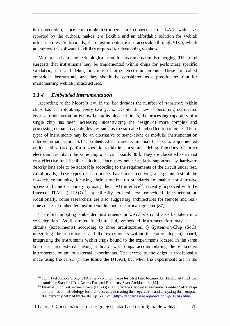
Chapter 3: Considerations for designing standard and reconfigurable weblabs 51
instrumentation, since compatible instruments are connected to a LAN, which, as
reported by the authors, makes it a flexible and an affordable solution for weblab
infrastructures. Additionally, these instruments are also accessible through VISA, which
guarantees the software flexibility required for developing weblabs.
More recently, a new technological trend for instrumentation is emerging. This trend
suggests that instruments may be implemented within chips for performing specific
validation, test and debug functions of other electronic circuits. These are called
embedded instruments, and they should be considered as a possible solution for
implementing weblab infrastructures.
3.1.4 Embedded instrumentation
According to the Moore’s law, in the last decades the number of transistors within
chips has been doubling every two years. Despite this law is becoming deprecated
because miniaturization is now facing its physical limits, the processing capability of a
single chip has been increasing, incentivizing the design of more complex and
processing demand capable devices such as the so-called embedded instruments. These
types of instruments may be an alternative to stand-alone or modular instrumentation
referred in subsection 3.1.1. Embedded instruments are mainly circuits implemented
within chips that perform specific validation, test and debug functions of other
electronic circuits in the same chip or circuit boards [85]. They are classified as a most
cost-effective and flexible solution, since they are essentially supported by hardware
descriptions able to be adaptable according to the requirements of the circuit under test.
Additionally, these types of instruments have been receiving a large interest of the
research community, focusing their attention on standards to enable non-intrusive
access and control, namely by using the JTAG interface55
, recently improved with the
Internal JTAG (IJTAG)56
, specifically created for embedded instrumentation.
Additionally, some researchers are also suggesting architectures for remote and real-
time access of embedded instrumentation and sensor management [87].
Therefore, adopting embedded instruments in weblabs should also be taken into
consideration. As illustrated in figure 3.4, embedded instrumentation may access
circuits (experiments) according to three architectures: i) System-on-Chip (SoC),
integrating the instruments and the experiments within the same chip; ii) board,
integrating the instruments within chips bound to the experiments located in the same
board or; iii) external, using a board with chips accommodating the embedded
instruments, bound to external experiments. The access to the chips is traditionally
made using the JTAG (in the future the IJTAG), but when the experiments are in the
55 Joint Test Action Group (JTAG) is a common name for what later became the IEEE1149.1 Std. that
stands for Standard Test Access Port and Boundary-Scan Architecture [86]. 56 Internal Joint Test Action Group (IJTAG) is an interface standard to instruments embedded in chips
that defines a methodology for their access, automating their operations and analyzing their outputs.
It is currently defined by the IEEEp1687 Std. (http://standards.ieee.org/develop/wg/IJTAG.html).

52 An IEEE1451.0-compliant FPGA-based reconfigurable weblab
board or externally located, the more common buses should be considered, such as the
RS-232, USB, LAN, or others.
Embedded instrument
Circuit (experiment)
under test
chip
JTAG
IJTAG
etc.
chip
JTAG
RS232
USB
LAN
etc.
Embedded instrumentEmbedded instrumentEmbedded instrument
Board
chip
Embedded instrumentEmbedded instrumentEmbedded instrument
BoardJTAG
RS232
USB
LAN
etc.
Embedded instrumentEmbedded instrument
Circuit (experiment)
under test
Interface drivers
a) System-on-Chip (SoC) b) Board c) External
Circuit (experiment)
under test
Figure 3.4: Architectures for embedded instruments in weblab infrastructures.
Although only architectures i) and ii) are traditionally adopted for embedded
instrumentation, architecture iii) may also be used, in particular for implementing
weblab infrastructures where traditional instruments (stand-alone or modular) can be
replaced by embedded instruments. Typical experiments able to be implemented using
architectures i) and ii) are those described through software, such as digital/analog
circuits implemented using reconfigurable devices, such as FPGAs or Field
Programmable Analog Arrays (FPAAs). However, these two architectures do not allow
the conduction of any type of experiment, since the interfaces are limited to the internal
circuits provided within the chips or boards. To promote the adoption of embedded
instrumentation for weblabs, architecture iii) should be considered, since it allows
interfacing any type of experiment using the I/O analog or digital interface drivers
provided by the board.
This diversity of technological solutions, both at hardware and software levels, for
implementing weblabs, are creating some difficulties for institutional collaboration and
resource sharing. Most weblabs use commercial devices adopting instrumentation
standards, but new technological solutions, such as embedded instrumentation, may be
considered for implementing the infrastructures. Additionally, current user-defined
applications use different APIs and architectures, which are difficulting the use of a
common platform for accessing weblabs and the provided experiments. This is
particularly true on interoperability issues, since weblabs traditionally use different
terminology and distinct metadata for their classification. These problems are impairing
the dissemination, integration and the interoperability of weblabs, which led to weblab
standardization initiatives.

Chapter 3: Considerations for designing standard and reconfigurable weblabs 53
3.2. On-going initiatives for weblabs standardization: GOLC
and IEEEp1876 Std.
The adoption of instrumentation standards gives an added-value for weblabs since
they can integrate in the same infrastructure several instruments accessible through
standard commands, APIs and drivers. Software developments and interoperability
among different types of instruments can be therefore facilitated, since they can
communicate using standard buses, and the software applications for the remote access
can then be reused. Besides the remote access to the adopted instrumentation, weblabs
should implement a set of requirements so they can be used in an educational context,
as already described in the previous chapter. They should provide most of the features
available in traditional laboratories, such as enabling the access to the equipment for
controlling and setting-up the experiments, facilitate the collaboration among students
when conducting experiments, among others. Additionally, the widespread of weblabs,
some providing experiments dedicated to specific engineering areas, alerted the
educational community for the interest on spreading them as much as possible, so that
they can be accessed all around the world and included in engineering courses to
improve their curricula and/or to overcome the lack of facilities and equipments. Aware
of this situation, the research community, including teachers, has been involved in
projects focused on the development of software frameworks using ontologies for
organizing information about weblabs and their features, APIs for accessing the adopted
instrumentation, and architectures that facilitate their development and widespread
adoption. The most important projects that gave significative contributions in this
domain are: i) the iLabs57
that defines an architecture for designing distributed weblabs
independently of the adopted technology (already detailed in chapter 2); ii) the
Lab2Go58
project that describes a vocabulary model for weblabs, enabling them to be
searched according to their characteristics and provided experiments; iii) the Labshare59
that is a consortium in Australia that includes, among other projects, the NetLab
(already detailed in chapter 2) and a generic framework defined by the SAHARA Labs60
for setting up heterogeneous laboratories and; iv) the LiLa61
project that defines another
software framework for building a repository of weblabs using reusable educational
modules defined through the denominated LiLa Learning Objects, which are compatible
with SCORM62
objects, and therefore able to run in VLEs such as the Moodle63
. These
projects are well disseminated within the research and educational communities,
providing common and distinct features, all considered important for designing a
standard framework for weblabs. All are focused on the use of software frameworks for
57 http://ilab.mit.edu/, http://ilabcentral.org/ 58 http://www.lab2go.net/ 59 http://www.labshare.edu.au/ 60 http://sourceforge.net/projects/labshare-sahara/ 61 http://www.lila-project.org/ 62 Sharable Content Object Reference Model (SCORM) is a collection of standards and specifications
for web-based e-learning (http://scorm.com/). 63 https://moodle.org/

54 An IEEE1451.0-compliant FPGA-based reconfigurable weblab
implementing remote access to experiments, access management systems and the way
pedagogical contents are provided and integrated in a course. However, each project
uses its own architecture, which difficults their interface in a common, scalable and
sharable framework. This diversity of solutions alerted the research community for the
benefits of designing a unique and standard solution for developing and disseminating
educational laboratories, in particular the weblabs.
As a result of a series of discussions commenced in early 2009, on June 25th
2010 the
Global Online Laboratory Consortium (GOLC)64
formally came into existence as an
independent organization. GOLC is an initiative of the iLabs founders that aims to
promote the development, share and research of online laboratories for educational use,
focusing on a software framework that supports their integration in education,
independently of the adopted technology. GOLC is mainly supported by the know-how
acquired from the referred projects, from contributions of the VISIR project created at
BTH65
, and from the Weblab-Deusto research group66
. It integrates several members
(individuals and organizations) organized into committees, as represented in figure 3.5.
Main contributers
·LiLa (Library of Labs)
· iLabs
·Lab2Go
·LabShare (SAHARA Labs)
·VISIR (BTH)
·Weblab-Deusto
- development, share and research on online labs
- framework to support the integration of different laboratories (e.g. weblabs) in education
Members(Voting or Non-voting Members that can be
individuals or organizations)
Committees & Working Groups(Executive Committe and Membership forum,
Committees and Interest groups established by the
GOLC Executive Committee )(Global Online Laboratory Consortium)
Figure 3.5: Overview of the Global Online Laboratory Consortium.
Members are divided into groups, according to the type of institution, the voting and
the advisory rights within the consortium. All provide an annual contribution to support
activities of the consortium including annual meetings that have been commonly
organized in parallel with the REV67
and FIE68
international conferences. The
committees include: i) the Executive Committee, who is the responsible for the overall
governance and oversight; ii) the Membership and Communications Committee, who
manage members and is the responsible for communications and; iii) the Technical and
Education Committees who are responsible for handling the entire research aiming for a
common technical and educational framework for online laboratories. Currently, GOLC
64 http://www.online-lab.org/ 65 http://openlabs.bth.se/ 66 https://www.weblab.deusto.es 67 Remote Engineering & Virtual Instrumentation (REV) (http://www.rev-conference.org/) is a series
of annual events in the area of remote engineering and virtual instrumentation. The REV
conferences are the annual conferences under the umbrella of the International Association of
Online Engineering (IAOE) (www.online-engineering.org). 68The annual Frontiers in Education (FIE) conference is a major international conference about
educational innovations and research in engineering and computing (http://fie-conference.org/).

Chapter 3: Considerations for designing standard and reconfigurable weblabs 55
committees are being redefined according to a different structure, but with the same
objectives. The Executive Committee is maintained, but the other committees will be
replaced by a membership forum, and a set of committees and special interest working
groups established by the GOLC Executive Committee. Applications such as booking
systems, descriptions of the offered experiments, terminology and interoperability
issues are some of the technical issues under discussion. Defining narratives for good
practice in the use of online laboratories (e.g. library of videos showing their effective
use), a standardized vocabulary for tagging research papers, metadata for describing
educational aspects, and guidelines for assisting users with the selection of an online
experiment, are some educational objectives currently under GOLC research and
development.
Based on previous projects, GOLC is currently working on technical documents to
be applied for online laboratories: i) the adopted terminology; ii) an ontology able to be
described using a set of metadata profiles and; iii) an interoperability standard for
accessing the laboratories. The terminology currently proposed uses a set of core
concepts illustrated in figure 3.6a). These are adopted by the ontology represented in
figure 3.6b) that is described through metadata profiles divided according to sets of
packages. These define features and components belonging to a laboratory, such as the
applied booking system, the rig attributes (in the scope of this thesis is an instance of the
weblab infrastructure), interaction issues, such as the required plug-ins to install in the
clients’ accessing devices, media packages for supporting pedagogical contents, and
others. The interoperability standard mainly defines the APIs and interaction models for
accessing the online laboratories.
Interaction package
Media package
Media dataMedia
Metadata
Rig
Physical Rig or Simulation Server
Rig configuration and options
Rig Metadata
communicates to
Learning activity
task
(experiment)task
Rig Set
Rig
interface equipment apparatus
Rig
a) Terminology relations b) GOLC ontology (packages and interaction with a rig defined according to metadata)
Metadata defined for each package and for the rigs
using classes and elements for describing the laboratory
Rig driverRig selection and
configurationInteraction Metadata
selects configures
Figure 3.6: Current terminology and ontology defined by the GOLC.
A more recent initiative supported by the IEEE standards association is also
emerging for the standardization of online labs. The members of this initiative that
belongs to the IEEE Networked Smart Learning Objects for Online Laboratories
Working Group (NSLOL WG), have agreed that laboratory work is a requirement for
any engineering course and currently online labs, which include weblabs, are seen as a
fundamental resource. Since the smart learning environments (traditionally adopted by

56 An IEEE1451.0-compliant FPGA-based reconfigurable weblab
weblabs) are built using different approaches, the NSLOL WG is involved in
developing the IEEEp1876 - Standard for Networked Smart Learning Objects for
Online Laboratories69
. The main goal of this standard is to establish the relationship
between all the involved components in a remote experimentation scenario (software,
hardware and learning systems) in order to facilitate the design and implementation of
pedagogically driven remote experiments. The first meeting was held in 2012 and more
recently another meeting was held at the IEEE EDUCON’201370
conference. In this
conference, some papers were presented with different solutions for developing online
laboratories, focusing on a new ontology [88], a proposal for designing interoperable
bridges among different laboratories [89], and new development paradigms [90][91].
Currently, no other developments are known about the IEEEp1876 Std., but the NSLOL
WG is open to receive new members and contributions, such as from the on-going
European research project named Go-Lab [92]. This project intends to create a large
federation of online laboratories involving the use of a technical framework designed to
support the construction and the exploitation of learning spaces.
Both the GOLC and the NSLOL WG (IEEEp1876 Std.) initiatives intend to gather
several researchers, so their developments and solutions may contribute for the
standardization of online labs. They are mainly focused on defining the software
frameworks for describing and accessing the laboratories, which, according to the
layered structure defined in the previous section (figure 3.2), position them as user
defined applications. Despite fundamental, the hardware is underestimated in both
initiatives, in particular for the possibility of using a standard for designing and
accessing instrumentation and for enabling their reconfiguration in a weblab
infrastructure. These aspects, together with the several solutions still running in parallel,
incentivized researching the use of a standard that specifies software and hardware
layers for designing weblabs, namely the IEEE1451.0 Std.
3.3. Using and extending the IEEE1451.0 Std. for designing
weblabs
The IEEE1451.0 Std. was specified to network-interface transducers in a plug&play
basis. This section introduces the IEEE1451.0 Std. and presents other family members.
The most disseminated projects and research work, which involve the use of this and
other members of the IEEE1451.x Std. family, are also presented, and some
considerations for applying the IEEE1451.0 Std. in the design of weblabs are discussed.
69 http://ieee-sa.centraldesktop.com/1876public/ 70 The IEEE Global Engineering Education Conference is a series of conferences that rotate among
central locations in IEEE Region 8 (Europe, Middle East and North Africa). The IEEE EDUCON
2013 was held at the Technische Universität Berlin, Berlin, Germany from March 13-15, 2013
(http://www.educon-conference.org/educon2013/).

Chapter 3: Considerations for designing standard and reconfigurable weblabs 57
3.3.1 Overview of the IEEE1451.0 Std.
The IEEE1451.0 Std. [93][94] aims to network-interface transducers (sensors and
actuators) and defines a set of operating modes, based on specifications provided by
Transducer Electronic Data Sheets (TEDSs). Defined in 2007 as an initiative of the
National Institute of Standards and Technology (NIST)71
, this standard is the basis for
forthcoming and previous members of the IEEE1451.x family [95][96], so they can
operate together to provide a unified interface. The operating modes defined by the
standard are controlled using commands that can be applied using a set of APIs. All
transducers are referred as smart since they support different modes of operation and
interfacing controlled by a set of TEDSs, i.e. data structures with information that
enable to define, control and monitor the smart transducers functional specifications
using software applications. Through TEDSs, the transducers are classified as sensors or
actuators, it is indicated the data they acquire/generate, are specified timing and
synchronization issues, among others. This standard does not define a communication
protocol for interfacing transducers. It establishes standardized interfaces, defined
according to other IEEE1451.x Stds., for using wired or wireless protocols (e.g. USB or
Bluetooth), in an architecture based on the reference model illustrated in figure 3.7.
TIMTIM
1451.1
application
(optional)
single URL
application
(HTTP-
1451.0
API)
other
applications
1451.0
Ser
vic
es
Tra
nsd
uce
r se
rvic
es A
PI
1451
.x c
om
munic
atio
n m
odule
Module
com
munca
tions
AP
I
NCAP
1451
.x c
om
munic
atio
n m
odule
Module
com
munca
tions
AP
I
1451.0
Ser
vic
es
Sig
nal
condit
ioner
/ A
DC
/ D
AC
1451
.4 T
ED
S r
eader
(opti
onal
)
Tra
nsd
uce
r m
easu
rem
ent
inte
rfac
e
TEDS
TEDS
TIM
Tra
nsd
uce
r an
alog i
nte
rfac
e
Tra
nsd
uce
r(es
)
PHY
1451.2
1451.3
1451.5
1451.6
use
rs n
etw
ork
physi
cal
worl
d
low
-lev
el c
om
mands
Transducer Interface ModuleNetwork Capable Application Processor
Figure 3.7: Reference model of the IEEE1451.0 Std.
The IEEE1451.0 Std. architecture includes one or more Transducer Interface
Modules (TIMs) connected to a Network Capable Application Processor (NCAP) using
communication modules defined according to other IEEE1451.x Stds. and accessed
using a Module communication API. The aim of these intermediate standards is to
provide a plug&play capability for all transducers, so the Transducer services API may
access every TIM through the Module communication API and independently of the
adopted physical layer. The TIM implements a set of services accessed using
commands, issued by the Module communication API, for controlling and monitoring
the transducers according to TEDS specifications, and it may use the IEEE1451.4 Std.
71 http://www.nist.gov/el/isd/ieee/ieee1451.cfm

58 An IEEE1451.0-compliant FPGA-based reconfigurable weblab
[97] for adding plug&play capabilities to analog transducers. The NCAP may include
TEDSs, implements a set of services accessed through the Transducer services API, and
is able to be remotely accessed using: i) the object model and interface specification
defined by the IEEE1451.1 Std. [98]; ii) the standard IEEE1451.0-HTTP API to send
commands, or; iii) other proposals, such as the Smart Transducer Web Services
[99][100]. The IEEE1451.0 Std. must operate with other IEEE1451.x Stds. so it can
bind transducers according to the adopted physical interface, such as point-to-point,
distributed multi-drop, wireless or others. Most current IEEE1451.x Stds. were defined
before the appearance of the IEEE1451.0 Std., and some are intended to be redefined or
created in the future. Table 3.2 resumes current IEEE1451.x standards according to
information retrieved from the IEEE Standards Association (IEEE-SA) and provided in
[94].
Table 3.2: The IEEE1451.x Std. family.
IEEE1451.0 - 2007 Defines a set of common operations and TEDSs for the IEEE1451.x family.
The functionality is independent of the TIM-NCAP physical interface [93].
IEEE1451.1 - 1999
Defines a common object model and programming paradigm for smart transducers. Runs on the NCAP and describes communications between
groups of NCAPs and higher-level systems supported by a network-neutral
interface [98]. It is an active standard compatible with the IEEE1451.0 Std.
and is being revised by the IEEEp1451.1 Std. working group.
IEEE1451.2 - 1997
Defines a TIM-NCAP interface and TEDS for point-to-point configurations.
Transducers are part of a Serial TIM (STIM). The original standard describes
an interface layer based on the serial SPI interface with additional lines for
flow and timing control. It is an active standard being revised to support
other popular serial interfaces such as UART and USB, and to become
compatible with the IEEE1451.0 Std. [101].
IEEE1451.3 - 2003
Defines a TIM-NCAP interface and TEDS for multi-drop transducers. It
allows transducers to be arrayed as nodes, on a multi-drop network, sharing a
common pair of wires [102]. It is an obsolete standard, no longer maintained.
IEEE1451.4 - 2004
Defines the protocol and the interface so analog transducers may
communicate digital information with an IEEE1451 object [97]. It is currently active and compatible with the IEEE1451.0 Std. The
IEEE/ISO/IEC 21451-4 standard [103] published in 2010 adopts this
IEEE1451.4 Std. and the IEEE1451.2 Std.
IEEE1451.5 - 2007
Defines an interface for sensors specifying radio-specific protocols, such as
Wi-Fi (IEEE802.11 Std.), Bluetooth (IEEE802.15.1 Std.) or ZigBee
(IEEE802.15.4). It defines communication modules that connect a Wireless
TIM (WTIM) and the NCAP [104]. It is currently active and compatible with
the IEEE1451.0 Std.
IEEEp1451.6 - 2007
Defines a TIM-NCAP interface and TEDS using the high-speed CANopen
network interface (Controller Area Network)72. Maps TEDSs to the
CANopen dictionary entries as well as communication messages, process
data, configuration parameters, and diagnosis information. Adopts the
CANopen device profile for measuring devices and closed-loop controllers. It has not yet been published as an IEEE standard.
IEEE1451.7 - 2010
Defines data formats, designed to facilitate communications between Radio
Frequency Identification (RFID) systems, TEDSs and commands for smart
RFID tags [105]. It is currently active and compatible with the IEEE1451.0
Std., but it has been superseded by the ISO/IEC/IEEE21451-7-2011 [106].
72 Control Area Network (CAN) - is a message-based protocol, designed specifically for automotive
applications but also used in other areas such as aerospace, industrial automation and medical
equipment (http://www.can-cia.de/).

Chapter 3: Considerations for designing standard and reconfigurable weblabs 59
3.3.2 Overview of current projects and research
Despite the inherent complexity of the IEEE1451.x Stds. [107], they have been
applied for interfacing transducers in several domains. Many research works have been
published in the last years, demonstrating the interest received from research groups and
companies. One of the first implementations was a framework developed at the NIST
using the IEEE1451.1/.2 Std. describing an Internet-based distributed measurement and
control system [108]. So different types of TIMs may interface the NCAP, this last was
suggested to be implemented by a μC able to be dynamically reprogrammable
[109][110]. Other publications suggest architectures for remote accessing IEEE1451.2-
based transducers for controlling a robot wrist using the CAN bus [111], and for
temperature control using a quartz transducer implemented in a μC [112]. The
advantages of using the IEEE1451.1/.2 Std. were discussed for implementing flexible
and distributed time-services, so they can meet real-time demands with synchronized
clocks [113], and there are implementations using FPGA devices [114][115][116], some
based on embedded processors [117], and a proposal for using FPGAs and FPAAs for
implementing IEEE1451.4-compliant sensors [118]. After the publication of the
IEEE1451.0 Std., research has been focused on its adoption for network-interface
transducers. Some examples can be pointed, such as: i) a system for monitoring and
diagnosing power transmissions lines [119]; ii) a proposal for an home healthcare
monitoring system [120]; iii) an integration analysis of electronic equipments into
intelligent road-traffic management systems [121]; iv) a server with the IEEE1451.0-
HTTP API implemented using LabVIEW web services for accessing real-time data
from a marine sensor network [122], among others.
In order to interface several NCAP through the network layer, some suggestions to
improve their architectures have been suggested. Two examples can be mention, namely
an implementation using the Microsoft .NET framework that provides communications
based on XML73
messages through the enhancement of the IEEE1451.1 Std.
[123][124], and an unified web service based on SOAP74
messages that uses the
IEEE1451.0 and the IEEE1451.5 Stds. to interface Wi-Fi networks [99][100].
Additionally, a recent work alerted for security on web services communications. It
proposes a cross-layer mechanism that deals with the requirements of authentication,
integrity, confidentiality, and availability across the communication process in smart
transducers [125].
Recent projects can be found in the Open1451 Project website75
, which provides a
repository with implementations, examples, and free applications of the IEEE1451.x
Std. Currently, it integrates 3 free projects: i) an IEEE1451.0 implementation in Java
73 eXtensible Markup Language (XML) is a markup language that defines rules for encoding
documents in human/machine-readable format (http://www.w3.org/XML/). 74 Simple Object Access Protocol (SOAP) is a protocol for exchanging structured information in the
implementation of Web Services in computer networks (http://www.w3.org/TR/soap12-part1/). 75 http://sourceforge.net/projects/open1451/

60 An IEEE1451.0-compliant FPGA-based reconfigurable weblab
using SunSPOTs76
; ii) a multiplatform library to debug TEDSs and; iii) a
communication protocol plug-in for WireShark (formerly known as Ethereal)77
for
parsing basic IEEE1451.1 packets and argument arrays. Although most of the solutions
are essentially supported by research groups, there are also companies that have been
developing compatible IEEE1451.x modules, for instance: Microchip, which has a
Serial TIM (STIM) implemented according to the IEEE1451.2 Std. [126]; the NI, which
provides LabVIEW applications for adapting sensors to the IEEE1451.4 Std.78
; and
some other companies, which have IEEE1451 compatible products, such as the
Esensors79
, Telemonitor80
or Senit81
.
3.3.3 Adopting the IEEE1451.0 Std. for weblabs
Adopting the IEEE1451.0 Std. for designing weblabs is an interesting and promising
approach since it defines an architecture supported by software and hardware layers for
developing smart transducers and for enabling their remote and standard access [25].
These smart transducers can be designed as instruments [127] or dedicated modules
commonly adopted in weblabs (i.e. the weblab modules). Per example, a sensor can be
an Oscilloscope and an actuator can be a Function Generator, both typically used in
electronic workbenches. These, or other weblab modules, can then be embedded within
one or more TIM bound to the experiments, and able to be remotely accessed using
standard commands provided by NCAP APIs.
Despite the IEEE1451.0 Std. requires the use of an interface described by another
IEEE1415.x Std., some of these are currently not yet compatible. Per example, the
IEEE1451.2 Std., adopted for NCAP-TIM serial communications, is not yet compatible,
despite some suggestions [128] and implementations [129]. Furthermore, the adoption
of these intermediate standards may increase the complexity of the developments,
requiring more technological resources for implementing a weblab infrastructure.
Removing the intermediate layers, namely the Module communication API,
implemented by an IEEE1451.x Std., and the Transducers services API, is therefore a
solution to take into consideration, since the standardized remote access is guaranteed
by the use of IEEE1451.0-HTTP API to issue IEEE1451.0-commands. Establishing a
map between the methods provided by the API (or the object model defined by the
IEEE1451.1 Std.), provided by the NCAP, and the commands, provided by the TIM,
should be taken into account when adopting this simplified architecture. This is an
option that simplifies developments but, at the same time, reduces part of the plug&play
flexibility provided by the intermediate layers implemented by the IEEE1451.x Std., in
particular when different NCAP-TIM physical connections are adopted (e.g. when the
NCAP is connected to different TIMs using distinct physical connections such as Wi-Fi
76 http://www.sunspotworld.com/ 77 Ethereal is a network analyzer now denominated as WireShark (http://www.wireshark.org/). 78 http://www.ni.com/sensors/ 79 www.eesensors.com/ieee-1451.html 80 http://www.telemonitor.com/ieee1451.html 81 http://www.senit.biz/

Chapter 3: Considerations for designing standard and reconfigurable weblabs 61
or Serial). Nevertheless, using the proposed simplified architecture for adopting the
IEEE1451.0 Std. in the design of weblabs, still guarantees the plug&play capability
between the TIM and NCAP modules, in particular when the mapping between the
commands provided by the NCAP APIs and the commands provided by the TIM is well
defined.
The TEDSs are the core of the IEEE1451.0 Std., and they can provide an added-
value for designing weblab architectures. Besides describing each weblab module and
the TIM, they can also be used for describing weblabs, indicating their location, the
pedagogical and technical resources they provide, among others. The information
traditionally defined as metadata elements for describing weblabs can be defined within
TEDSs since, according to the IEEE1451.0 Std., it is possible to define the so-called
Manufacturer-Defined TEDS. The information can then be accessed (for read or write)
using the same commands issued by standard APIs, namely by the IEEE1451.0-HTTP
API, which is one solution for accessing the weblab modules and the entire weblab.
The standardized access, using the APIs, may also facilitate the implementation of
automatic monitoring tools. The adoption of intelligent tutoring systems [130] is
facilitated, since all commands issued to the weblab (for accessing weblab modules and
TEDSs) can be logged for automatic analysis. Currently, this solution can be greatly
facilitated by the adoption of the communication protocol dissector plug-in for
WireShark, available in the Open1451 Project website82
. The assessment results can be
automatically provided for students’ and/or teachers’ analysis, and a feedback of all
actions made during an experimental activity can be automatically monitored and
retrieved, fulfilling some of the learning goals pointed out in chapter 2 (e.g. the Learn
from failure goal that suggests students must get feedbacks of their actions during an
experimental activity).
The last aspect that incentivized considering the use of the IEEE1451.0 Std. as a
complementary solution for designing weblabs resulted from the detailed functionalit ies
defined for designing the smart transducers, and therefore the weblab modules. The
provided description allows defining each weblab module independently of the adopted
technology, which facilitates selecting the most appropriate one for providing the
reconfiguration capability for a particular infrastructure. The different modules may
then be defined according to the standard and the adopted technology and, since
reconfiguration is not considered in the IEEE1451.0 Std., extending the APIs for this
purpose is a possibility to take into consideration. Additionally, the different described
layers also allow splitting tasks during developments, facilitating and promoting
collaboration between institutions during the design of weblabs.
Therefore, using the IEEE1451.0 Std. for designing weblabs is interesting and very
promising, since it defines a standard architecture for accessing smart transducers (the
weblab modules), and describes development issues supported on TEDSs’ contents.
82 http://sourceforge.net/projects/open1451/

62 An IEEE1451.0-compliant FPGA-based reconfigurable weblab
Furthermore, the IEEE1451.0-HTTP API allows a standardized access to the weblab
modules. The API provides methods for issuing commands to read and control the
weblab modules’ states and to access the associated TEDSs. The independence of the
adopted technology for implementing the architecture and the modules is also
important. Reconfiguration can be implemented by extending some aspects of the
standard, namely the available commands and the TEDSs, which can be used for
describing the weblabs including the provided experiments, technical resources for
reconfiguring the underlying infrastructure, and others.
Therefore, in order to design IEEE1451.0-compliant and remotely reconfigurable
weblabs able to accommodate different modules running in parallel, lead to consider the
use of reconfigurable technology.
3.4. Providing reconfigurability to weblabs through FPGAs
Changing the weblab modules according to the requirements of an ongoing
experiment requires using reconfigurable technology [131]. For this purpose two issues
must be analysed: i) the infrastructural one, namely the hardware required for its
implementation and; ii) the architecture, which enables its remote configuration with
different modules and the access to the experiments following a standard, such as the
IEEE1451.0 Std.
3.4.1 Infrastructure
Traditional weblab architectures include PCs acting as instrumentation servers with
individual instruments connected through instrumentation buses and accessed according
to different software architectures. Although these solutions guarantee high performance
by using dedicated instruments (stand-alone or modular), they can be expensive
including features eventually not necessary for conducting some experiments. To reduce
costs and to target a general architecture for implementing weblabs with reconfiguration
capabilities, there are technologies that can be adopted to accommodate different
modules. These can be implemented within chips as embedded instruments, and
selected according to the requirements posed by a specific experiment.
The use of FPAAs is a potential solution for implementing a weblab infrastructure,
since they allow embedding Analog and Mixed Signal (AMS) circuits, which could be
the weblab modules required for conducting an experiment. However, current FPAAs
still integrate few configurable analog blocks, and there is only a reduced number of
products in the market (e.g. Anadigm83
) with the reconfiguration processes too much
manufacturer dependent. Despite the available languages for describing AMS circuits
(VHDL-AMS [132], Verilog-AMS84
, and SystemC-AMS85
), they are not being used by
current FPAA development tools. Describing weblab modules as embedded instruments
83 http://www.anadigm.com/fpaa.asp 84 http://www.designers-guide.org/VerilogAMS/ 85 http://www.systemc-ams.org/

Chapter 3: Considerations for designing standard and reconfigurable weblabs 63
using HDL-AMS does not guarantee compatibility among the available FPAAs’
architectures and, due to the reduced number of analog blocks they provide, only a
limited number of modules could be described. Additionally, the reconfiguration of
these devices does not allow selecting every type of voltage and current levels, which
would still require the use of external drivers for interfacing the weblab infrastructure to
the target experiments. Adding all these considerations to the manufacturing difficulties
for integrating many analog circuits into a single chip, suggests disregarding FPAAs as
a good solution for designing reconfigurable weblabs.
Although not bringing the same analog reconfiguration capability provided by
FPAAs, there are currently two well tested technological solutions facing continuous
improvements that may be considered for designing reconfigurable weblab
infrastructures, namely: μCs/μPs and FPGAs. Both allow implementing digital circuits
that, due to the current digital signal processing techniques, allow implementing almost
every type of circuits available in the analog domain (e.g. filters, comparators, and
others) able to use in weblab infrastructures. Although μCs/μPs have well defined
hardware architectures with high processing rates and functionalities changing
according to software code, they do not have the same flexibility guarantied by FPGAs
that may be reconfigured with several cores specifying μCs/μPs, dedicated controllers,
and the required weblab modules (annex A provides an overview of an FPGA internal
architecture). Rather than using specific manufacturer dependent languages, those cores
may be described through standard HDLs (VHDL [133], Verilog [134], or SystemC
[135]), and the multitasking is facilitated, since developers have low-level control over
the hardware, regardless of the manufacturer, which enables running multiple weblab
modules in parallel like instruments in a traditional laboratory. Typically, FPGAs have
several I/O pins and, currently, their processing rates are approaching those of μCs/μPs.
Although the reconfiguration capability provided by FPGAs may be seen as an
interesting advantage when compared to other solutions, they can only work with digital
I/O signals, which is not sufficient for implementing weblab infrastructures. FPGAs
need to acquire/supply analogue signals from/to the experiments; and the analogue
signals may have different voltages and currents levels, which require external drivers
to interface to the experiments. To overcome these issues, there are nowadays many
FPGA-based boards bringing associated components such as: A/D and D/A converters,
memories, LCD displays, interface ports, etc. (annex B shows an example of an FPGA-
based board). Since these boards provide the required analog interfaces to access the
target experiments, and the reconfiguration capability of FPGAs, they are seen as the
most indicated hardware platforms for implementing a reconfigurable weblab. As
illustrated in figure 3.8, they may accommodate the weblab modules as embedded
instruments and replace the instrumentation server, plus specific instrumentation buses
traditionally adopted for their interface.

64 An IEEE1451.0-compliant FPGA-based reconfigurable weblab
Internet
Weblab server
Instruments
& Modules
(I&M)
Instruments
& Modules
(I&M)
Weblab
moduleExternal devices,
modules(e.g. robots)
Target experiments
Instrumentation server
Replaceable by
FPGA-based boardsWeblab infrastructure
Instrumentation bus
Webcam
Figure 3.8: FPGA-based reconfigurable weblab infrastructure.
At this moment, one should consider possible limitations due to insufficient FPGA
resources for accommodating all the required weblab modules, at the same time. To
overcome this limitation, figure 3.9 illustrates two possible architectures: i) using one
FPGA with several weblab modules or; ii) using one FPGA for each weblab module.
Although the second architecture is technically easier, since each defined module is
embedded in different FPGAs, not requiring specific routing tasks inside them, costs
may increase. Additionally, the required physical space will also be higher to
accommodate the infrastructure, when compared to the first architecture that uses a
single FPGA to accommodate all the modules.
FPGADedicated
Controller
Osc
illo
sco
pe
Multimeter
FPGA
Function
Generator
Multimeter
Fu
nct
ion
Gen
erat
or
FPGA
Target
experiment
a) one FPGA for several weblab modules b) one FPGA for each weblab module
Target
experiment
Figure 3.9: Architectures for embedding weblab modules in FPGA-based boards.
Although both architectures may be applied together or independently, typically the
first architecture may impose more technical challenges than the second one, since it
implies a more regular swap of modules within the FPGA. This situation occurs when a
single FPGA does not have enough space for accommodating several instruments at the
same time. This is illustrated in the first architecture of figure 3.9, that represents a
situation that a single FPGA encapsulates several instruments (a Multimeter, a Function
Generator and a dedicated Controller) and a new one (an Oscilloscope) is required for
conducting a particular experiment. Since the FPGA does not have enough space to
accommodate all the instruments at the same time, an instrument swapping mechanism
is required to be implemented. This can be made using two reconfiguration options
provided by FPGA technology, namely: i) total reconfiguration or ii) partial

Chapter 3: Considerations for designing standard and reconfigurable weblabs 65
reconfiguration (using static or dynamic approaches). Total reconfiguration requires
reconfiguring the entire core of the FPGA for swapping a particular instrument, which
implies stopping the weblab operation. By using partial reconfiguration only part of the
FPGA is reconfigured, i.e. the space occupied by a particular instrument. This may
require stopping the weblab when adopting a static approach or it may keep running
when using a dynamic approach (these aspects are further discussed in annex C).
In addition to all these considerations and advantages of using FPGAs for
implementing reconfigurable weblabs, it is also fundamental to understand and analyse
how to remotely access them to conduct an experiment and to reconfigure the
infrastructure with different weblab modules.
3.4.2 Remote access
Typically, weblabs use several modules that require a web interface for their remote
access. All modules and their interfaces should be shared, so the entire community may
reuse them to reconfigure the infrastructure, and new remote experiments may be
created. For this purpose, it is suggested an architecture similar to the one illustrated in
figure 3.10, where at least one main weblab interface must be available from the
infrastructure or from the weblab servers.
Internet
HDL files describing the weblab modules
Weblab infrastructure
web serverWeblab server
main weblab interface
Interfaces for each weblab module
mobile phones, PDAs, smart phones, tablets or PCs E
ther
net
PH
Y
Figure 3.10: Proposed weblab architecture using FPGA-based weblabs.
The main weblab interface provides a bridge to the other resources available in
weblab servers, i.e. the HDL files describing the weblab modules and their interfaces. It
should provide a mechanism to transfer the HDL files into the FPGAs, and the weblab
interfaces, used for remotely access each module, into the users’ accessing devices.
Since all resources may be distributed among different servers, the amount of available
memory in the FPGA-based board is not relevant. At the same time, this architecture
facilitates collaboration among institutions, allowing them to share and reuse the weblab
modules and their interfaces.

66 An IEEE1451.0-compliant FPGA-based reconfigurable weblab
Additionally, the weblab infrastructure must allow remote users to access the
embedded weblab modules. Two solutions may be considered for this purpose, namely:
Hybrid, by using an independent Micro Web Server (MWS) connected to the
FPGA-based board;
System-on-Chip (SoC), by using a TCP/IP core inside the FPGA.
Hybrid solution
The hybrid solution uses a MWS connected to an FPGA-based board, as illustrated
in figure 3.11. Inside this MWS an interface implemented through any web software
language (e.g. HTML, JAVA or other) is available, so users may access the
infrastructure. Connecting the MWS to the Internet, through the Ethernet physical
interface, allows accessing the experiments using a set of I/O signals or a JTAG
interface, typically provided by all FPGA-based boards.
Internet
Micro
Weblab
Server
(MWS)
Digital I/O
JTAG
Target
experiment
Analog
DigitalWeblab moduleE
ther
net
PH
Y
I/O
I/O
FPGA-based board
D/A
A
/D
Weblab infrastructure
I/O
Figure 3.11: Hybrid solution for remote accessing weblab infrastructures.
Users typically download the interface from the MWS to their accessing devices for
accessing the MWS pins. Some run as switching I/O signals, while others control the
JTAG infrastructure. Commonly, this test infrastructure is used to reconfigure an FPGA
and should also be adopted if the number of pins required to monitor the FPGA is
higher than those available in the MWS. By using the weblab interfaces, users may
control the modules inside the FPGA, which send or receive data from/to the target
experiment using A/D and D/A converters, or digital I/O signals. The advantage of this
solution is related to the simplicity of the implementation, since there are already
several MWS available in the market whose offer is expected to grow in the near future.
Noteworthy, some MWS are implemented into FPGAs, which illustrates the power and
wide acceptance of these devices for building microelectronic circuits [136] and the
capability they offer for implementing a weblab infrastructure. Based on a web search,
table 3.3 presents a selection of commercial MWS able to support and provide a remote
access to the weblab modules.

Chapter 3: Considerations for designing standard and reconfigurable weblabs 67
Table 3.3: A selection of commercial MWS.
Company Product Website
Lantronix XPort AR; Micro100 http://www.lantronix.com/
Olimex CS8900A-H http://www.olimex.com/
Microchip PICDEM.net™ 2 http://www.microchip.com/
Cyan USB/Ethernet Module http://www.cyantechnology.com/
NetBurner SB70LC Serial.-Eth. http://www.netburner.com/
Modtronix SBC65EC http://www.modtronix.com
Typically, each MWS allows users to establish a web connection to access its I/O
pins, and some provide several Internet services such as FTP, HTTP, SSH and Telnet,
among others. However, this solution requires at least two devices (FPGA + MWS), and
each MWS has specific characteristics hampering its adaptation to different weblab
infrastructures. Therefore, depending on the chosen MWS, prices may be higher and
flexibility may be lower when compared to a SoC solution.
SoC solution
In the SoC solution, the FPGA has an embedded TCP/IP core. As illustrated in figure
3.12, the TCP/IP core will send/receive commands through the Internet to access all
weblab modules accommodated inside the FPGA.
Internet Weblab moduleT
CP
/IP
core
Eth
ernet
PH
Y
FPGA-based board
Target
experiment
Analog
Digital
I/O
D/A
A
/D
Weblab infrastructure
Figure 3.12: SoC solution for remote accessing weblab infrastructures.
All commands are sent using a specific weblab interface available from a weblab
server or from a memory located in the FPGA-based board. Once downloaded to the
remote accessing device, the interface allows a user to control/monitor the experiment
through a set of I/O pins (digital or analog), in the same way as in the hybrid solution.
Two options are available for implementing the SoC solution: a) using an
independent TCP/IP core, or b) using a TCP/IP core dependent of a commercial μC/μP
core. Usually, in both solutions TCP/IP cores are sold by companies. However, using a
solution dependent of a μC/μP core will not guarantee the platform independence
required for a weblab infrastructure, since they only work with a specific μC/μP
embedded as a soft/hard core inside the FPGA. A solution based on an independent
TCP/IP core is therefore preferred, because it is usually described through HDL files

68 An IEEE1451.0-compliant FPGA-based reconfigurable weblab
accepted by any Integrated Development Environment (IDE)86
. After some research on
the web, table 3.4 presents several TCP/IP cores, where only Xilinx provides a μC/μP
dependent core. Nevertheless, since low prices and high flexibility are the main goals
for building a reconfigurable weblab infrastructure, the use of stand-alone TCP/IP cores
is considered the most appropriated solution. These can be found in the OpenCores
website that is being constantly fed with different modules described through HDL files.
Table 3.4: A selection of TCP/IP cores.
Company Product Website
IP Cores WPA2 802.11i for Wi-Fi http://www.ipcores.com/
System Level IPRETHTMFP001-Eth. MAC http://www.slscorp.com/
Sarance High Speed Ethernet IP http://www.sarance.com/
OpenCores Eth. MAC 10/100/1000 Mbps http://www.opencores.org/
Xilinx Ethernet Lite MAC http://www.xilinx.com/
HiTech Global 40G/100G Eth. MAC & PC http://www.hitechglobal.com/
CAST MAC-10/100 Eth. Lite http://www.cast-inc.com/
Aurora VLSI SSN8006:Eth. 10/100 MAC http://www.auroravlsi.com/
Although the SoC solution does not require the use of MWSs, it is considered less
indicated for designing reconfigurable weblabs than the hybrid solution, because: i)
TCP/IP cores may use too many resources of the FPGA, which limits the weblab
modules able to adopt, at the same instant, in the infrastructure; ii) the reconfiguration
process is hard to implement, since it requires routing techniques to connect the weblab
modules (partial reconfiguration); iii) the use of some TCP/IP cores depends on the
FPGA manufacturer (less flexibility), and requires the use of FPGAs with partial
reconfiguration capabilities (higher costs) and; iv) when adopting the infrastructure for
providing the weblab interfaces or for managing the access to the modules, traditionally
the memory space provided in FPGA-based boards is reduced, since this is mainly
adopted to accommodate HDL files used to reconfigure the FPGA core.
Thus, table 3.5 resumes the 4 options for designing a weblab infrastructure based on
hybrid architectures and supported by FPGA technology, taking into account the
number of FPGA versus the number of weblab modules required for conducting a
remote experiment.
Whatever the adopted solution, using FPGA-based boards is an opportunity for
simplifying the design of weblab infrastructures, since they can be reconfigured with
several weblab modules described through HDL files. Developing all weblab modules
and accommodating them inside an FPGA as embedded instruments, can be made using
the reconfiguration capabilities provided by current FPGA technology. However, to
promote collaboration among institutions and to facilitate the development of weblab
infrastructures by sharing those modules, requires following rules, so different
institutions and developers may easily split tasks for creating a specific weblab module.
Therefore, it is important to follow a standard for their development, specifying the
86 Usually manufacturers support the required changes to adapt TCP/IP cores for a specific FPGA.

Chapter 3: Considerations for designing standard and reconfigurable weblabs 69
HDL files and the weblab interfaces that enable their remote access. Two solutions
allow fulfilling these main requirements: i) specify a specific standard or; ii) adopt an
already existing standard, such as the IEEE1451.0 Std. Technical aspects of the first
solution were discussed and presented in [131], which describes the implementation of a
Function Generator (FG) in a single FPGA-based board.
During the development phase there was an institutional collaboration between ISEP
and the Heriot-Watt Univesity (HWU). ISEP developed the HDL files describing the
FG, while the weblab interface for its remote control was developed by HWU. Since no
standard was adopted for controlling the FG, a specific one was defined at ISEP, which
posed many problems, since HWU developers had to familiarize themselves with all
protocol details. This fact delayed developments and alerted for problems arising from
failing to adopt standards for creating and sharing the weblab modules. To overcome
the limitations already detected and other potential ones, solution ii) is viewed as the
best choice, in particular using the IEEE1451.0 Std.
Table 3.5: Considerations about the number of FPGAs versus the weblab modules
required for implementing a reconfigurable infrastructure based on an hybrid
architecture.
Number of FPGAs
1 N
Nu
mb
er o
f w
eb
lab
mo
du
les
1
- Costs may increase, since traditionally a
weblab requires using more than one weblab
module, which implies more than one FPGA;
- Some of the space in the FPGA can be unused, when a particular module only
occupies a small part of it;
- Total reconfiguration is the preferable
choice, since there is a unique module to
reconfigure.
- Only adopted if an FPGA does not offer
enough space to accommodate the entire
weblab module;
- Total reconfiguration is the preferable choice, since each FPGA is occupied by
only a part of a single weblab module.
N
- Most cost effective solution;
- Total or partial reconfiguration are
suggested according to the requirements of
the weblab operation, i.e. if swapping a
module should not stop the weblab operation
then partial dynamic reconfiguration is
preferable, otherwise total or partial static reconfigurations should be adopted.
- Merges all the other solutions, bringing
more reconfiguration complexity;
- Weblab modules may be distributed by
one or more FPGAs and they can
accommodate part of or an entire module;
- Total or partial reconfiguration may be
applied, but the complexity can explode.
As already referred in subsection 3.3.3, the IEEE1451.0 Std. provides all details for
developing and interfacing transducers (sensors/actuators), which can be the weblab
modules. This standard is an added-value for designing the weblab infrastructures since
it specifies a layered architecture providing software and hardware guidelines,
supported by TEDSs, which can be used to control and describe weblabs. Additionally,
by describing the weblab modules using standard HDL, such as Verilog, VHDL or
SystemC, the independence from FPGA manufacturers is addressed. Depending on the

70 An IEEE1451.0-compliant FPGA-based reconfigurable weblab
available FPGA resources (logic blocks, internal memories, I/O blocks, and others),
every module can be embedded into any FPGA, since the associated IDE traditionally
allows describing the modules using the referred standard HDL.
Therefore, associating the characteristics of the IEEE1451.0 Std. to the
reconfiguration capability of FPGAs addresses the problems of current weblabs listed in
chapter 2 (section 2.6), namely:
weblab architectures and underlying infrastructures can be standardized using
the IEEE1451.0 Std. reference model;
all weblab modules are accessed (controlled and monitored) through standard
APIs;
institutional collaboration may be improved, since the weblab modules are
embedded into an FPGA and described through HDL files according to the
IEEE1451.0 Std., enabling their reuse, sharing and replication through different
infrastructures;
the redesign of the infrastructure is ensured, since the weblab modules can be
swapped and redefined according to the requirements of a particular experiment;
since a common standard is followed, the development of weblabs (architecture,
infrastructure and modules) is facilitated, incentivizing joint collaboration efforts
from different institutions;
costs can be reduced, since the infrastructures adopt embedded instruments
rather than traditional ones, all able to be redefined and replicated through HDL
files. Additionally, the instrumentation server may be suppressed, since all
weblab modules are interfaced inside the FPGA, without using instrumentation
buses controlled by specific software applications;
the infrastructure becomes more stable requiring less maintenance, since by
removing the instrumentation server, the traditional software problems caused
by their upgrade are vanished, and;
the possibility of easily sharing weblab modules and integrating them in
standardized infrastructures incentivize the adoption of weblabs in different
courses, overcoming possible technical limitations faced by institutional staff
(the human actors involved in the educational context).
3.5. Summary
The adoption of weblabs for conducting experimental work activities is considered
an added-value for engineering education. Several and distinct architectures have been
created using instruments interfaced by different standards. Those instruments were
classified in two types (stand-alone or modular), and considerations about their adoption
for designing weblab architectures were discussed, presenting the most relevant

Chapter 3: Considerations for designing standard and reconfigurable weblabs 71
instrumentation standards, namely the buses and the software frameworks, drivers and
APIs that allow developing software applications for their interface and remote access.
The use of hybrid architectures was also referred as an actual and future trend to design
weblabs, justified by the many interfaces, based on instrumentation standards, provided
by commercial instruments. A particular attention was paid to embedded
instrumentation as a possible solution to consider when designing new weblab
infrastructures.
The diversity of technological solutions and weblab architectures led to a lack of
standardization in their design, which promoted the appearance of two competing
standardization initiatives (GOLC and IEEEp1876 Std.), both presented in this chapter.
Since these initiatives essentially focus on the software frameworks for accessing and
managing the weblab resources, using traditional instrumentation, a possible
complementary solution based on the IEEE1451.0 Std. was suggested and presented.
After an overview of this standard, its family members and current research and
projects, the added-value that the IEEE1451.0 Std. can bring to the design of weblabs
was discussed, together with some considerations about the use of FPGA technology for
enabling the remote reconfiguration of a weblab infrastructure.
Finally, the use of FPGAs as an alternative to other technologies, and the way they
can be reconfigured using embedded weblab modules required for conducting a
particular experiment was justified and presented. A possible architecture and two
solutions for designing the underlying infrastructure were suggested. This chapter ended
referring the importance of using standards for design and accessing the weblab
modules indicating in which way the IEEE1451.0 Std. and FPGA technology may
address the problems faced by weblabs referred in the previous chapter. The following
chapter details the IEEE1451.0 Std., the architectures and extensions applicable to this
standard, so that it can be used for designing reconfigurable weblabs.

72 An IEEE1451.0-compliant FPGA-based reconfigurable weblab

Chapter 4: The IEEE1451.0 Std. as a smart framework for weblabs 73
Chapter 4
The IEEE1451.0 Std. as a
smart framework for weblabs
The IEEE1451.0 Std. was considered an interesting and promising solution for
designing weblabs. This chapter details the most important issues covered by this
standard. It describes the reference model and the technical and functional aspects of the
associated modules named NCAP and TIM. A special attention is given to data
structures named TEDSs, since their contents define the entire operation of smart
transducers that, in the scope of this thesis, are the weblab modules required to control
and monitor the target experiments. Different types of TEDSs are presented, as well as
their structural and functional characteristics. A number of solutions for designing
weblab infrastructures, as a part of the proposed IEEE1451.0 Std. enhanced architecture
and supported by the NCAP and TIM smart operations and associated models, are then
described. At the end, the use of weblab infrastructures supported by a simplified
approach for the NCAP-TIM reference model is suggested.

74 An IEEE1451.0-compliant FPGA-based reconfigurable weblab

Chapter 4: The IEEE1451.0 Std. as a smart framework for weblabs 75
4.1. Reference model: NCAP and TIM smart modules
The IEEE1451.0 Std. was specified in 2007 as a common basis for the whole Std.
family [93]. It aims to network-interface sensors and actuators (transducers) in a
plug&play basis, and to remotely access them through the web, using standard
commands. As illustrated in figure 4.1, it follows a reference module based on a NCAP
connected to one or more TIMs using different physical (PHY) protocols ruled by
interfaces defined by other IEEE1451.x Stds.
InternetNCAP
(Network Capable
Application Processor)
External
transducersTEDSTEDSTEDS
HT
TP
-14
51.0
AP
I
TEDSTEDSTEDS
Mo
du
le
com
mu
nic
atio
n A
PI
Co
mm
and
s
Mo
du
le
com
mu
nic
atio
n A
PI
TC(Transducer Channel)
Virtual
PHY
1451.2
1451.3
1451.5
1451.6
.........
Tra
nsd
uce
r se
rvic
es
AP
I ...TIM
(Transducer
Interface Module)
Figure 4.1: Reference model of the IEEE1451.0 Std.
Both the NCAP and the TIM are smart, since they combine processing units with
communication interfaces, and implement a set of services and APIs that enable
remotely accessing the transducers according to specifications defined in TEDSs. These
TEDSs can be implemented in the TIM, in the NCAP, or remotely located (the last two
named virtual TEDSs). There are mandatory and optional TEDSs, and each one is
divided into several groups of fields able to be read/written using a set of commands for
controlling and monitoring Transducer Channels (TCs). TCs run as transducers and
implement all associated signal conditioning and conversion components. They can be
completely contained within a TIM (named as embedded TCs) or connected to the
physical world to acquire or generate physical quantities into/from internal buffers
named Data Sets (DSs). Additionally, they can be bound to other transducers making
them smart, since they become remotely accessible and controllable according to the
IEEE1451.0 Std.
The generic characteristics of all TIMs are defined through single and mandatory
Meta-TEDSs. The TCs are defined by mandatory TC-TEDSs that specify associated
features such as: the units and ranges of the monitored/controlled physical phenomena,
data sampling and time control issues, and in particular their types, namely:
actuators - accept data samples and convert them into an action within or outside
the TIM;
sensors - convert physical, biological, or chemical values into electrical signals
that will be handled by the TIM, or;
event-sensors - detect changes in the physical world to trigger specific actions
within the TIM.

76 An IEEE1451.0-compliant FPGA-based reconfigurable weblab
Both TIMs and TCs are recognized by addresses, operate on specific states, and have
associated status registers to monitor their events and errors. To control the TCs, the
IEEE1451.0 Std. provides a set of mandatory and optional commands divided into
classes and functions. They can be issued to the TIM, to a specific or group of TCs, or
to both, depending on the selected addresses and on their operating states. This means
that a command can only be accepted if a TC or a TIM is in a compatible operating
state, otherwise an error message is reported, and an internal status register bit is set.
When a particular event occurs (e.g. an internal or external event is detected), the TIM
can send an automatic message to the NCAP using a TIM-initiated message.
To interface TIMs to the NCAP, the standard defines the Module communication
API. This is a symmetric point-to-point and network interface implemented on NCAP
and TIM sides, and contains methods to register and access the IEEE1451.x layer. It
works as a wrapper on top of commands, providing interfaces to manage NCAP-TIM
communications independently of the selected physical protocol and associated
IEEE1451.x Std. The NCAP uses the Transducer services API for accessing internal
services, and to access/manage TCs and TEDSs. This API can be remotely accessed
using the HTTP-1451.0 API that contains methods to read and write TCs and TEDSs,
and to send configuration, control, and operation commands to TIMs.
Error and event detection mechanisms are also implemented both in the NCAP and
in the TIM. The NCAP provides a set of codes indicating error sources, while the TIM
uses the status registers to indicate other specific errors and information about the
operation of the TIM and of each TC. In both situations, this information can be
accessed using the referred APIs or it can be automatically transmitted through TIM-
initiated messages when an internal status-event protocol is enable. This protocol is
activated using particular commands and is ruled by internal logic controlled by a set of
registers able to be read/written, so users may easily debug all errors and control the
TIM and the TCs.
Beyond these mandatory smart features, the IEEE1451.0 compatible infrastructure is
essentially managed by TEDSs, which are the most important components of the
standard. Therefore, it is important to analyse their structure and the way they are
accessed and managed.
4.2. Transducer Electronic Data Sheets
The smart operations described in the IEEE1451.0 Std. are defined by TEDSs, whose
contents can be binary, text-based or user-defined, all identified by a specific ID code.
They are defined as data structures divided into group of fields describing all
characteristics and features of the TIM and of each TC. As referred in the previous
section, there are mandatory and optional TEDSs, each one grouping related
information. As conceptualized by figure 4.2, there are 4 mandatory TEDSs required for
designing compatible IEEE1451.0 devices, namely:

Chapter 4: The IEEE1451.0 Std. as a smart framework for weblabs 77
Meta-TEDS [binary content] - defines generic features such as: timing
parameters for NCAP-TIM communications, and the number and groups of TCs
within a TIM;
User’s Transducer Name TEDS [user-defined content] - required for the TIM
and recommended for all TCs, provides a place to store their names;
PHY-TEDS [binary content] - provides read-only information for accessing each
TC and the TIM, according to the adopted IEEE1451.x Std. for the NCAP-TIM
interface, and;
TransducerChannel TEDS (TC-TEDS) [binary content] - specifies
characteristics and operational issues of a TC.
Meta-TEDS TC-TEDS
........................
External
transducers
TC(Transducer Channel)
User’s Transducer Name TEDS
User’s Transducer Name TEDS
TC-TEDSUser’s
Transducer Name TEDS
PHY-TEDS
TIM (Transducer Interface Module)
NCAP
(Network Capable
Application
Processor) PHY
Figure 4.2: Mandatory TEDSs in an IEEE1451.0 compatible device.
There is one Meta-TEDS for the entire device. It has binary content and, besides
defining timing parameters of the NCAP-TIM communications, it specifies the number
of available TCs, all identified by sequential addresses. In order to control/monitor
physical phenomena, TCs can be grouped as a:
control group, to control a phenomenon that uses related TCs (e.g. one can run
as an event-sensor that when detecting a particular event, triggers other grouped
actuators);
vector group, essentially used to group actuators for defining particular
mathematical relationships (e.g. defining a 3-dimensional axis);
proxy group, for combining proxy TCs87
and;
specialized vector group, for providing information about their geographic
location.
87 A proxy TC is an artificial construct used to combine I/Os of multiple TCs into a single structure. It
is assigned to an address and may be read or written, but it does not have the other characteristics of
a TC such as the TC-TEDS and other associated TEDSs. It represents either a sensor or an actuator
but never represents both. It may use two methods for combining DSs, namely: block method that
allows DSs with different lengths, or the interleaved method that uses DSs with the same length.

78 An IEEE1451.0-compliant FPGA-based reconfigurable weblab
There is also one PHY-TEDS for the entire device. It has binary content and depends
on the adopted IEEE1451.x Std. since it provides static information about the PHY
protocol adopted for the NCAP-TIM interface. This TEDS is important for
implementing the plug&play capability, enabling commands sent to the NCAP to
transparently access a particular TC according to the adopted PHY protocol. Both the
NCAP and the TIM should decode the information provided by the PHY-TEDS, so they
can be easily interfaced.
The User’s Transducer Name TEDS is adopted for associating a name to the TIM
and to the TCs. It can have binary, text-based or any other user-defined contents. The
TIM must have an associated name, while the TCs’ names are optional, despite
recommended by the standard. This means that at least one of these TEDSs must be
defined.
Although the relevance of both User’s Transducer Name and PHY TEDSs, TC-
TEDSs provide all detailed and relevant information about each TC. Each TC-TEDS is
associated to a particular TC and is divided into distinct groups defining operational
aspects such as: the calibration capability, its type (actuator, sensor or event-sensor), the
data able to acquire/generate specific physical units and ranges of values over which it
operates, timing and sampling information, operation modes, among others. The TIM
must read the TC-TEDSs before starting the operation of a particular TC, since they
define all device characteristics.
Besides mandatory TEDSs, there are optional ones for specifying particular
characteristics of IEEE1451.0 compatible devices. They are not required to be
implemented, but they provide additional information about the TIM and about each
TC, such as additional commands, geographic location, extensions to the units defined
by mandatory TC-TEDSs, calibration and mathematical operations required to manage
acquired/generated data, and other user-defined aspects. The optional TEDSs can be
divided according to their data contents, as documented in the diagram of figure 4.3 that
also depicts the group of mandatory TEDSs previously described.
Text-based TEDSs belong to an optional class. They provide data structures
encapsulating one or more blocks of textual information presented in specific languages
and encoded in XML. In order to promote the compatibility of the IEEE1451.0 Std.
with the other family members, this same class integrates a subclass of identification
TEDSs. Binary TEDSs focus on operations for handling data, while user-defined
TEDSs may be implemented for adding other additional information, such as the
Manufacturer-Defined TEDSs (MD-TEDSs) that can provide additional fields for
characterizing the operation of a particular TC.

Chapter 4: The IEEE1451.0 Std. as a smart framework for weblabs 79
Meta-TEDS
TC-TEDS
PHY-TEDS
User's Transducer Name TEDS
binary
Mandatory TEDSs
user-defined
Commands-TEDSSpecifies additional commands.
Geographic location-TEDS
Units extension-TEDS
Indicates the TIM location installation.
Includes text for extending SI units.
Represents TEDSs defined by other standards.
text-based
Constants necessary to convert sensor and actuator data into engineering units.
Characterize the frequency and phase response of a TC.
Series of constants used to describe TCs’ transfer functions (e.g. Z transform).
Location and Title-TEDS
Location for TCs (e.g. URL) and any other user-defined information.
Meta id-TEDS
TC id-TEDS
Calibration id-TEDS
identification TEDS
Transfer Function-TEDS
Frequency Response-TEDS
Calibration-TEDS
binary
Optional TEDSs
Storage for application-dependent data user wants to keep with the TIM or TC (much like the User's Transducer Name TEDS).
Enables users to define any type of information.
End User Application
Specific-TEDS
Manufacturer-defined-TEDS
user-defined
Figure 4.3: Diagram illustrating the group of TEDSs defined in the IEEE1451.0 Std.
Every TEDS (mandatory or optional) is defined by 8-bit data structures divided into
3 blocks of fields, namely:
the length, to indicate the current size;
a data block, to gather the main information and;
the checksum, to verify the data integrity.
Figure 4.4a) illustrates all these blocks, and the number of octets used by each one.
The length block uses 4 octets for defining the size of the remaining data blocks. Since
the size defined through these octets includes the 2 octets used by the checksum block,
it means that the data block may have up to 2^32 - 2 (4.294.967.293) fields. The last 2
octets, used by the checksum, keep the result of a one’s complement of the sum of all
octets, included in the length and the data block. A TEDS is validated by comparing this
checksum with another similar calculation using the current data block, reducing the
changes of erroneous operations that may occur in IEEE1451.0 devices.
Length
Data
Checksum
4 octets
variable
2 octets
Type Length Value1 octet Δ octets Δ octets
TEDS data
TLV IDentification header
Type (3)
Length (4)
Family
Class
Version
Length
Valu
e
TLV structure
a) TEDS structureb) TLV IDentification header sub-block in the data block (common to all TEDS)
Δ-variable
Figure 4.4: Structure and identification header defined for all TEDSs.

80 An IEEE1451.0-compliant FPGA-based reconfigurable weblab
While the length and the checksum blocks have a limited and fixed size, the data
block has a variable size and its fields differ according to the adopted TEDS. Since the
information available in the data block defines the device operation characteristics, each
field must be able to be read/written by the TIM itself, and by the remote users through
standard commands. For this purpose, all fields within the data block are organized
according to Type-Length-Value (TLV) structures, as represented in the same figure
4.4a). In these structures, each field has a specific size and implements a particular task.
The Type occupies 1 octet and identifies the TLV structure defined for a particular
TEDS. The Length has a size defined in a TLV IDentification header represented in
figure 4.4b). It is adopted for specifying the number of octets of the value field that has
the main data. Although every TEDS has its own TLV structures, the IDentification
header is a sub-block common to all TEDSs that indicates the number of octets used for
defining the Length field in a TLV structure (length), the IEEE1451.x Std. family
(family), the TEDS access ID code (class) and its version (version).
TEDSs have a set of particular and associated characteristics that rules their access
and update. Although not mapped in their structures, they must be specified according
to a set of attributes, indicating if they are: read-only, virtual, text-based, or unsupported
for a particular TC, among others. It is also up to the manufacturer (or developer) to
specify some other associated characteristics, such as the status during a particular
access and its maximum size. Annex D provides examples of TEDSs’ structures,
namely the Meta-TEDS and the TC-TEDS, and required attributes and status.
The access to the TEDSs’ fields is made using four of the commands that will be
described in subsection 4.3.5, namely QueryTEDS, ReadTEDSsegment,
WriteTEDSsegment and UpdateTEDS, whose arguments must indicate the target TC(s)
or the TIM, and the TEDS access ID code. All provide replies indicating if they were
successfully executed, and only WriteTEDSsegment command does not retrieve
additional information about the accessed TEDS. These commands can be issued
through the APIs defined by the IEEE1451.0 Std., thus reducing their inherent
complexity that requires using a particular command message format, as described in
subsection 4.3.4.
4.3. Smart modules: access and operation
The IEEE1451.0 Std. does not suggest any particular technology for designing
compatible devices. While the NCAP focus on network issues, mainly on the APIs and
some network services, the TIM focus on most of the smart features provided by the
TCs, namely: an addressing mechanism to identify TCs, their operating states and
modes, and a set of status registers for monitoring the operation of a device using a
service request generation logic and a status-event protocol. Additionally, it also defines
type of messages (command, reply and TIM-initiated), and a set of standard commands
to control IEEE1451.0 compatible devices.

Chapter 4: The IEEE1451.0 Std. as a smart framework for weblabs 81
4.3.1 Addressing mechanism
Both TIMs and TCs are recognized through two addressing levels. The first
addresses are the destination ID used by the NCAP to identify a particular TIM. The
second addresses specify to the TIM how should a message be issued to a particular or
group of TCs or to the TIM itself, and to tell to the NCAP where a specific reply
message or TIM-initiated message came from.
As represented in figure 4.5, the NCAP can access several TIMs, identified by their
IDs, and these can have four types of addresses defined through a 16-bit word, namely:
a global address, adopted when a particular message is associated to all TCs;
group addresses, which identify a group of TCs;
TC addresses, which identify a particular TC and;
a TIM address, which indicates that a particular message is associated to the
TIM and not to any particular or group of TCs.
NCAP
TIMID
(...)
Gro
up a
ddre
ss
TC address
TC address
TC address
TC address
TC address
TC address
Gro
up a
ddre
ss
TC address
Glo
bal
addre
ss
TIM
addre
ss
TIMID
TIMID
IDGlobal address = 0xFFFF
0x8000 <= Group address <= 0xFFFE
0x0001 <= TC address <= 0x7FFF
TIM address = 0x0000
Pro
cess
ing
un
its
1 0 0 0 1...
1 1 0 1 1...
OR logic
Bit mapped [0x8000 – 0xBFFF]
Group 1
Binary [0xC000 – 0xFFFE]
Group Address(max. 2^14-1=16383)
Gro
up
ad
dre
ss
Figure 4.5: Addressing mechanism used by the IEEE1451.0 Std.
All addresses are associated to a specific or to a range of addresses indicated in
hexadecimal format in figure 4.5. The TIM and the global addresses have a fixed value
of 0x0000 and 0xFFFF respectively. The TCs’ addresses have a value between 0x0001
and 0x7FFF, which means that one TIM may have up to 32767 TCs. The group
addresses have a value between 0x8000 and 0xFFFE. In order to send/receive messages
to/from multiple groups, these addresses can be defined according to two possible
solutions: i) bit mapped or ii) binary.
The bit mapped solution is used when few group addresses are needed and it is
desired to send a command to multiple groups at the same time. The address value must
be between 0x8000 and 0xBFFF, which means that the most two significative bits have
the binary value 10, and the remaining ones indicate the group address. This way, it is
possible to use an OR logic approach for referring more than one group.

82 An IEEE1451.0-compliant FPGA-based reconfigurable weblab
The binary solution is used when a large number of group addresses are required.
The address value must be between 0xC000 and 0xFFFE, which means that the two
most significative bits are always set, and the remaining ones define the group address
number. This means that a TIM may have up to 16383 groups using the binary solution,
while when using the bit mapped solution only 14 groups are available, despite able of
being addressed simultaneously using an OR logic.
4.3.2 Operating states and modes
During the operation of a smart device, the TIM and each TC operate in pre-defined
states running processes according to the state diagrams illustrated in figure 4.6. The
TIM has a unique state diagram, while each TC has its own state diagram enabling their
independent operation. The state transitions are automatically handled during the device
operation or when users send some particular commands. Both TIM and TCs start by an
initialization process that, when completed, place the TIM in the active state and each
TC in the idle state. The TIM must remain active so each TC may go to the operating
state or latter repositioned in the idle state using the Reset or TCIdle commands. The
dependence between the TIM and each TC is also evident when the TIM goes to the
sleep state caused by a Sleep command. When this occurs, all TCs go to the idle state
becoming inactive and requiring to be enabled to start running, and therefore, to be
(re)positioned in the operating state.
operating
idle
active
TCidlecommand
TIM sleepstate
Reset command
Enable TCoperatecommand
initialization
Initialization complete
Reset or Power On or
TIM Initialization
state
initialization
sleep
b) TC operating states
Reset or Power On
Sleep command
Timeout
Custom
Wake-Up command
a) TIM operating states
Initialization complete
Trigger
Figure 4.6: TIM and TC operating states.
When in the operating state, the TCs may run in different data sampling and data
transmission modes according to what is defined in their associated TC-TEDSs. Most of
these modes are ruled by trigger signals that can be applied by particular commands or
internally generated. They depend on the selected sampling modes and on the way a TC
runs (sensor, event-sensor or actuator). Due to the very specific information provided by
the trigger states diagrams, it was decided to present them in annex E of this thesis.
As represented in figure 4.7, a sampling mode defines the way a TC acquires/outputs
data into/from its DSs, and the data transmission mode represents the way those same
samples are transmitted/received to/from the NCAP.

Chapter 4: The IEEE1451.0 Std. as a smart framework for weblabs 83
Data-Set (DS)
DS
Sampling mode
TIMNCAP
Transmission mode
TransducerChannel (TC)
DSDS
Figure 4.7: Conceptual diagram of the TIM operation modes.
A TC may run as a sensor, an event-sensor or an actuator in up to 5 sampling modes,
and operate with other complemented modes specified in the associated TC-TEDS,
generically described in table 4.1. The data available within DSs are sent to the NCAP
according to 3 transmission modes, detailed in table 4.2, that are also specified in the
associated TC-TEDSs.
Table 4.1: IEEE1451.0 main TC sampling modes and complemented modes.
Main sampling modes
Trigger initiated
Available for TCs operating as sensors and actuators. After a trigger signal
they start storing data into DSs (sensors) or outputting data from the DSs
(actuators) until all are processed.
Free-running without
pre-trigger
Available for TCs operating as sensors and actuators. TCs operating as a
sensors start receiving data after entering in the operating state. All data are
discarded until the reception of a trigger. Once received, the data are stored in
DSs until they become full. TCs operating as actuators start outputting data
after entering in the operating state according to the End-of-DS operation mode defined in its TC-TEDS.
Both types of transducers stop their operation if they leave the operating
state. If triggers are received during data reception or outputting, the DSs are
placed in their first position used to store/output a sample.
Free-running with
pre-trigger
Available for TCs operating as sensors with or without buffers enabled. They
start acquiring data into DS(s) after entering in the operating state and stop if
a DS is completed (number of samples in a DS = DS size - pre-trigger count
value defined in the associated TC-TEDS). If a trigger is received, they start
storing samples into another DS if operating with buffers enabled, or start
storing data samples again into the same DS if operating without buffers
enabled.
Continuous
Available for sensors, event-sensors and actuators. When operating as
sensors it is much similar to the Free-running without pre-trigger mode using
multiple buffers, but it does not require trigger signals to switch from DSs. When operating as event-sensors, they are able to detect changes in the
inputs and, once detected, store the samples into multiple DSs. When
operating as actuators, they start outputting samples from a DS when
receiving a trigger. When all samples were outputted from a DS they
automatically switch to others. It uses the End-of-DS operation mode when
the last DS outputs its last sample.
Immediate
Available for TCs operating as sensors or actuators, they are able to store
(sensor) or output (actuator) data in/from DSs only after the reception of
Read/WriteTCDSsegment commands.
Complemented modes
Buffer
Non-buffered
Defines the behaviour of the DSs for sensors and actuators, i.e. the way
samples available in the DSs are stored or sampled.
End-of-DS operation Method used by TCs operating as actuators for transmitting data when a DS
reaches its last sample (hold or recirculation).

84 An IEEE1451.0-compliant FPGA-based reconfigurable weblab
Streaming
operation
Applicable for TCs running in the continuous sampling operation mode, with
either the Streaming when Buffer full or Streaming at a fixed interval modes
(described in the next table). The TCs do not require any trigger signals or
commands for start storing or outputting samples into/from DSs.
Edge-to-report
operation
Used by event-sensors for defining transition signals detections modes
(falling transitions, rising transactions or all-transitions mode).
Actuator halt mode Defines what should do an actuator when it is in an idle state (halt
immediate, halt at the end of the DS or ramp to a predefined state).
Table 4.2: IEEE1451.0 TIM to NCAP transmission modes.
Commanded A TIM transmits data from a DS only in response to a ReadTCDSsegment
command.
Streaming when
Buffer full
Data are transmitted as soon as a DS is full without waiting for the NCAP to
issue a ReadTCDSsegment command.
Streaming at a fixed
interval
The DSs are transmitted at a fixed interval. The TIM can be designed to stop
using the current DS when it reaches a specified number of data samples. When this happens, the TIM can start transmitting data to the NCAP (without
waiting for a ReadTCDSsegment command) while using other DSs for storing
other data.
4.3.3 Status registers and the status-event protocol
In order to monitor the entire operation of a device, including internal events (e.g. an
internal trigger) and errors that may appear, the standard provides a set of 3 status
registers with 32 bits for each TC and for the TIM, namely:
condition registers, containing the current state of reported events and errors;
event registers, which gather the previous state of the condition registers after
the generation of a new event or error and;
masks registers, used to activate a Service Request (SR) generation when a
particular event or error occurs.
Each of the 32 bits indicates a particular event or error, some are optional, and they
are able to be read or written using specific commands. Annex F presents the status bits
defined for each TC and TIM.
To enable an automatic request of a particular TC or TIM, the status registers are
organized according to the status message generation logic illustrated in figure 4.8a). It
enables a SR signal (similar to an interruption) to be generated when a particular event
or error occurs in a TC or in the TIM itself. There is a single SR for each TC/TIM, but
traditionally these can be joined using an OR logic, which means that the entire device
can have a single SR, as illustrated in figure 4.8b). When this SR is generated and a so-
called status-event protocol is enabled, the device sends a TIM-initiated message to the
NCAP with a status message including the contents of the event register associated to
the TC and/or to the TIM that caused the SR.

Chapter 4: The IEEE1451.0 Std. as a smart framework for weblabs 85
bit31
bit30
bit29
bit28
bit1
conditionregister
bit31
bit30
bit29
bit28
bit1
eventregister
bit31
bit30
bit29
bit28
bit1
maskregister
bit0
bit0
read/clearstatus-event
Service Request
(SR)
SR TC 1
SR TC 2
SR TC n-1
SR TC n
SR TIM
...
a) status message generation logic for the
TIM and for each TC
b) TIM SRgeneration (optional solution)
OR
Figure 4.8: Status message generation logic and TIM SR generation.
4.3.4 Message structures at the PHY channel
There are 3 types of messages for accessing an IEEE1451.0 compatible device,
namely:
command messages, to send commands;
reply messages, for commands’ replies and;
TIM-initiated messages, for streaming data and for receiving status messages
(e.g. when the status-event protocol is enable).
As illustrated in figure 4.9, all these messages are divided into structures of octets,
each one representing particular information.
Destination address (most significant octet)Destination address (least significant octet)
Command classCommand function
Lenght (most significant octet)Lenght (least significant octet)
Command dependent octets
Success/Fail FlagLenght (most significant octet)Lenght (least significant octet)
Reply-dependent octets
01234567Octet bit order
01234567Octet bit order
Sig
nif
ican
ceo
rder
most
least
most
least
a) Command and TIM-initiated messages structures b) Command reply messages structures
Sig
nif
ican
ceo
rder
Figure 4.9: Message structures.

86 An IEEE1451.0-compliant FPGA-based reconfigurable weblab
Both command and TIM-initiate messages have the same structure. They use the first
two octets to indicate the destination address for a particular command or from where a
specific TIM-initiated message comes from (e.g. the TIM, a TC or a group of TCs). The
second two octets indicate the class and command identification (specified by the
command function) or, for TIM-initiated messages, the associated command that could
have generated the dependent octets indicated in the last octets. Before these dependent
octets (required for some commands), the structure provides the message length, which
is also used by the reply messages after indicating, through one bit, the success (1) or
the failure (0) when applying a command88
.
4.3.5 Commands
The IEEE1451.0 Std. provides two categories of commands: standard and
manufacturer-defined. All are issued using command message structures, and the replies
are provided by reply message structures. Regardless of the category, the commands are
divided into 2 octets. The most significant octet defines the class of the commands. The
least significant octet, called the function, identifies a specific command within the
class. There are mandatory and optional commands, and they can only be issued if the
TIM or a specific TC is in a compatible state, otherwise some are ignored and others
generate errors by setting bits in the status registers. Table 4.3 presents the different
classes of standard commands, exemplifying some of them.
Smart operations for an IEEE1451.0 compatible device are essentially implemented
by the TIM, according to TEDSs’ definitions. The devices may be designed using
different technological solutions, but they should implement all the described smart
operations able to be accessed through standard commands. These commands are
provided by the TIM and follow message structures whose fields are divided according
to different octets specifying distinct aspects, such as the addressed TC(s) or the TIM.
In order to let users remotely access these devices through standard commands, the
standard provides a set of APIs with methods to simplify and manage the access to the
referred commands, and therefore, to the smart transducers.
88 Messages may contain up to 65.535 octets plus the octets in the headers. If a message contains more
octets than can be sent with a single message, it is broken into multiple messages, named packets. It
is the responsibility of the data link layer, in the protocol stack, to break messages down into
multiple packets for transmission.

Chapter 4: The IEEE1451.0 Std. as a smart framework for weblabs 87
Table 4.3: Classes of standard commands.
0 reserved
1 Common commands
Required commands addressed to the TIM in the active state or to TCs in any state*. Reads, writes or
updates TEDSs (QueryTEDS, ReadTEDSsegment, WriteTEDSsegment, and UpdateTEDS); accesses the
status registers (e.g. ReadStatusEventRegister), and controls the status-event protocol operation (Read /
WriteStatusEventProtocolState). * the WriteStatusEventProtocolState requires the TCs in the idle state.
2 TC idle state commands
Addressed to all TCs in the idle state and to the TIM in the active state. Specifies the TCs’ operation
modes (e.g. BufferedState, SetTCdataRepetitionCount).
3 TC operating state
Addressed to a single TC. Requires all TCs in the operating state and the TIM in the active state.
Includes commands to read/write DSs’ segments (readTCDSsegment, writeTCDSsegment) and to control
triggers (TriggerCommand, AbortTrigger).
4 TC either idle or operating states
Addressed to a single TC in the operating or idle states, and the TIM in the active state.
Includes commands to change the TC operation states (TCoperate, TCidle) and to read or write some
TCs’ operating states (e.g.: WriteTCtriggerState).
5 TIM sleep state commands
Addressed to the TIM (address 0) in the sleep state. Implements a single optional command for forcing
the TIM to go to an active state (Wake-Up).
6 TIM active state commands
Addressed to the TIM (address 0) in the active state. Includes commands to read the TIM and the
IEEE1451.0 version (ReadTIMversion/IEEE1451.0Version), to store and recall operational setup
information (Store/RecallOperationalSetup), and to put the TIM into a low-power state (TIMsleep).
7 TIM any state commands
Addressed to the TIM (address 0) in any state. Implements a single and optional command to reset the
entire device, i.e. the TIM and all TCs (Reset).
8-127 Reserved
128-255 Open for manufacturers
4.4. The APIs: module communication, transducer services
and HTTP
The standard defines 3 APIs for the NCAP-TIM interface and for enabling the access
to the commands provided by the TIM. The APIs are organized according to a layered
structure represented in figure 4.10a), each one performing a particular role:
Transducer services interface - is a NCAP-only API used by measurement and
control applications to access the IEEE1451.0 layer. It provides methods for
reading and writing TCs and TEDSs, send configuration, control and operation
commands to the TIM. It defines an optional interface for supporting non-
blocking read/write operations and to receive data from measurement streams.
Module communication interface - is a symmetric interface implemented on the
NCAP and TIM sides containing methods implemented by an IEEE1451.x layer.
It specifies point-to-point and network interfaces.
HTTP API - is a NCAP-only API used for remotely accessing TIMs, TCs and
TEDSs using the HTTP 1.1 protocol.

88 An IEEE1451.0-compliant FPGA-based reconfigurable weblab
Module communcations API
Commands
Module communcations API
Transducer services interface API
HTTP APIApplications
Users
HTTP server (HTTP API)NC
AP
TIM
Utilpackage
Args package
IEEE1451.0
IEEE1451.x
IEEE1451.x
......
IEEE1451.x
.....
......
HTTPrequest
HTTPresponse
NC
AP
TIM
TIM
......................TCs
a) layered structure b) HTTP access
Figure 4.10: IEEE1451.0 Std. API layered structure and the HTTP schematic access.
The methods available in the APIs are supported by the Args and Util packages. The
Args package extends basic data types defined in the standard (e.g. Integers) to
structured types (e.g. IntegerArray). Additionally, it defines codes for specifying errors
originated from the physical NCAP-TIM interface or from the TIM itself, methods for
measurement the Quality of Service (QoS) on the communications, and others to
facilitate data manipulation. Data conversion methods are provided by the Util package
for encoding and decoding structured data types to/from octet arrays.
The logical communication between the NCAP and TIMs or between TIMs is
handled by the Module communication API. It is divided in two groups providing
methods for point-to-point or network communications. Each group defines three
interfaces: i) communication, implemented by the IEEE1451.x layer to control the
NCAP-TIM communications; ii) registration, to register the selected IEEE1451.x into
the system and; iii) receive, to notify the IEEE1451.0 layer that a message has been
received, or for aborting a communication.
The access to the TIMs is managed by the Transducer services API according to a
set of methods sequentially applied. It is entirely implemented in the NCAP side and
provides discovery methods for specifying the target TIM ID and TCs’ addresses.
Through the returned IDs the TCs are accessed using the transducer access methods.
These enable two types of TCs’ operations: i) blocking, where the TCs stop their
execution waiting for a read/write operation (stay blocked) and ii) non-blocking, where
the TCs wait (block) during a specific period of time (specified in a TEDS) for a
read/write operation before becoming unblocked. Other methods are provided in this
API for enabling a more precise control over the TIM, and in particular to handle
TEDSs’ data, namely by the possibility they provide to read, write or update TEDSs,
and to manage NCAP-side TEDSs’ cached information.
For enabling a remote access to the TIM, TCs and associated TEDSs, the
IEEE1451.0 Std. provides the HTTP API. As illustrated in figure 4.10b), the HTTP API
runs on an HTTP web server interfacing the other APIs. It is an optional solution, since

Chapter 4: The IEEE1451.0 Std. as a smart framework for weblabs 89
the standard permits the use of other applications designed according to the object
model defined by the IEEE1451.1 Std. [98], or the use of other proposals, such as the
Smart Transducer Web Services [99][100] that may facilitate network interfacing
NCAPs. Besides other available solutions, the HTTP API is the only described by the
IEEE1451.0 Std. for implementing simple client-server architectures (traditionally
implemented by weblabs). It provides the set of methods described in table 4.4 that
indicates the target NCAP (identified through its IP and port numbers), followed by the
path with the command and its parameters (arguments), using the following HTTP
message format:
http://<host>:<port>/<path>?<parameters>
Although the arguments are defined according to each command using the data types
specified in the Args package, all have in common the target TIM and TC. Additionally,
all specify the reply message format in an argument, which can be in XML, HTML or
text format.
This way, by using the HTTP API, it is possible to design thin or thick web
applications to run in the users’ accessing devices for remote accessing weblab modules
designed as smart transducers. The weblab infrastructures can be designed according to
the IEEE1451.0 Std., taking the advantage of its smart and standardized architecture
supported on TEDSs that define the operation of all TCs.
Table 4.4: IEEE1451.0 Std. HTTP API (paths and methods).
Discovery
1451/Discovery/TIMDiscovery Discovers IEEE1451.x communications modules,
TIMs and TCs. 1451/Discovery/TCDiscovery
Transducer Access
1451/TransducerAccess/ReadData
Reads and writes TCs.
1451/TransducerAccess/StartReadData
1451/TransducerAccess/MeasurementUpdate
1451/TransducerAccess/WriteData
1451/TransducerAccess/StartWriteData
TEDS Manager
1451/TEDSManager/ReadTeds
Reads and writes TEDSs and manages NCAP-
side TEDSs’ cached information.
1451/TEDSManager/ReadRawTeds
1451/TEDSManager/WriteTeds
1451/TEDSManager/WriteRawTeds
1451/TEDSManager/UpdateTedsCache
Transducer Manager
1451/TransducerManager/SendCommand
Provides control functions over TIM accesses,
e.g. to lock the TIM for exclusive use and to send
arbitrary commands to it.
1451/TransducerManager/StartCommand
1451/TransducerManager/CommandComplete
1451/TransducerManager/Trigger
1451/TransducerManager/StartTrigger

90 An IEEE1451.0-compliant FPGA-based reconfigurable weblab
4.5. Suggested weblab infrastructures compliant with the
IEEE1451.0 Std.
Besides providing several APIs for accessing transducers, the IEEE1451.0 Std.
defines their functional structure without specifying any particular technology for their
implementation. Taking into consideration the wide range of applicability provided by
the standard specifications, it is seen as an interesting solution to standardize the access
and the design of weblabs. The defined smart transducers implemented or accessed by
TCs, can be weblab modules, such as Oscilloscopes, Multimeters, dedicated
Controllers, among others, since they provide processing units and I/O interfaces to
access the target experiments. The access to these modules embedded (or not) in the
TIM, can be implemented through an architecture supported by an infrastructure similar
to the one illustrated in figure 4.11 that uses the NCAP-TIM reference model.
Internet
Weblab server
NCAP TIM
Weblab infrastructure
Target
experiment
Users
TC
weblabmodule
Embedded weblab module
TIMTC
Figure 4.11: Adopting the IEEE1451.0 Std. for designing a weblab infrastructure.
The weblab modules can be implemented inside or outside the TIM and designed or
accessed as smart transducers to interact with the target experiments. Embedded weblab
modules must be always designed according to the IEEE1451.0 Std. and bind to the
TIM using the same technological solution, such as FPGAs. Weblab modules outside
the TIM can be IEEE1451.0-compliant modules or stand-alone and modular
instrumentation originally not compliant with the standard. These instruments can
preserve their inherent characteristics (e.g. their particular accessing commands,
accessing buses and architectures) since it will be the TCs the responsible for
guarantying the compatibility with the standard. The weblab server integrates all
pedagogical contents and administrative tools for supporting a particular course and to
manage the accesses to the infrastructure (as already detailed in chapter 2).
Both NCAP and TIM can be implemented using any type of technology, and these
can either be separately defined, as an hybrid solution, or integrated in a unique device.
It is up to the developer to adopt one of these solutions, even though hybrid
architectures may provide a more versatile option since the NCAP and the TIM can be
more easily replaced. Whatever the adopted solution, the standard also permits the use
of several TIMs connected to a single NCAP, these also able to be interfaced through
the Internet. The option to use one or more TIMs and NCAPs depends essentially on the

Chapter 4: The IEEE1451.0 Std. as a smart framework for weblabs 91
available technology for their implementation, and on the required weblab modules for
conducting a particular experiment.
As illustrated in figure 4.12, four conceptual solutions can be identified for
implementing weblab infrastructures. The first uses a single NCAP-TIM connection to
access one target experiment. This is the simplest solution, and involves the adoption of
a simple point-to-point interface. The second solution also uses a single NCAP-TIM
connection, but the TIM interfaces different target experiments accommodating or
interfacing different weblab modules. Each module is adopted for a different experiment
placed in the same physical location. This solution intends to exploit all TIM resources
to access more than one experiment. The third solution uses more than one TIM
connected to the NCAP. It can be adopted for traditional experiments or for experiments
divided into several parts geographically dispersed, each requiring the use of dedicated
modules. It is also suggested when the device adopted for implementing the TIM cannot
accommodate or interface all required weblab modules. Through different physical
interfaces, in both cases the TIMs can be interfaced to a single NCAP providing the
remote access and all the services (eventually using virtual TEDSs) required for
managing the accesses to each weblab module and therefore to the target experiment.
The fourth solution can use any of the previously referred solutions since it focus on
interfacing NCAPs. It can be applied for situations when a particular weblab requires
more than one infrastructure to provide remote experiments. This is much like the third
solution where a particular experiment is divided into different parts geographically
dispersed. Nevertheless, in this solution the access management must be firstly handled
by an external weblab server that selects the appropriated infrastructure. Only after this
selection, the NCAP of the selected infrastructure may handle the access to the TIM(s)
to control/monitor the target experiment using the associated weblab modules.
Internet
TIM.........
TIM
Part
Target experiment(s) (parts geographically dispersed)
Part n Part n
TIM TIM
Weblab server
NCAP NCAP
NCAP
TIM
Target
experiment
NCAP
TIM TIM
Part I Part n
Target experiment(s) (parts geographically dispersed)
.........
TIM
.........
Target
experiment 1
NCAP
Target
experiment n
.........
.........
TIM
Target exp.
...
Figure 4.12: Possible weblab infrastructures based on the IEEE1451.0 Std.
Whatever the adopted solution for implementing the weblab infrastructure, some of
the characteristics provided by the IEEE1451.0 Std. can be extended to improve

92 An IEEE1451.0-compliant FPGA-based reconfigurable weblab
weblabs standardization and dissemination levels, in particular by designing enhanced
architectures for facilitating the dissemination of experiments and resources through the
educational community, implementing a reconfiguration capability and an assessment
mechanism during the conduction of a specific experiment. This way, weblabs can be
more easily adopted and selected as a tool for the conduction of the required laboratory
work in engineering education.
4.6. Extending the IEEE1451.0 Std. to enhance weblab
architectures
Despite the well defined architecture of the IEEE1451.0 Std. that led to the suggested
solutions, the access management to different weblabs and target experiments is an
important issue that can be implemented by other weblab architectures already
available. In chapter 2 some projects with well defined architectures were described,
namely the iLabs, NetLab and VISIR. Although the NetLab and the VISIR projects
have successful architectures, enabling a standard access to stand-alone and modular
instruments using the ISA and the VISA, each one has its own management system and
adopts commercial instruments for accessing the target experiments. Furthermore, they
are seen as complementary solutions since they were not designed to be integrated with
other architectures. The iLabs and other briefly referred projects, such as the LiLa and
the Lab2Go, follow a different approach. They have the objective of supporting
different architectures with software models and frameworks. Their acceptance by the
educational community is proved by their large influence in some of the most important
decisions in GOLC, which incentivize understanding how can the proposed
IEEE1451.0-compliant weblab infrastructures be adopted together with those
architectures.
Through the brief conducted analyses to iLabs, it was seen that its software
framework architecture is more focused on the access management to different types of
weblabs, implementing scheduling mechanisms. Therefore, adopting the iLabs
architecture89
[62] for managing the accesses to IEEE1451.0-compliant weblab
infrastructures may be considered. Mapping the iLabs APIs with the APIs defined in the
IEEE1451.0 Std. can be a solution for implementing this complementarity. The Lab
server suggested in iLabs can be implemented by one of the suggested weblab
infrastructures defined in the previous section, integrating this way the iLabs access
management system. The LiLa project90
, that also implements scheduling systems,
stands out for having a collection of SCORM compliant learning objects that can be
included into VLEs, such as Moodle. This can be adopted for integrating pedagogical
contents for the conduction of experimental activities in engineering courses. The last
relevant project is the Lab2Go that can be the basis for describing the features of the
suggested weblab infrastructures, since it provides a Metadata - Reference Model
89 http://ilab.mit.edu/, http://ilabcentral.org/ 90 http://www.lila-project.org/

Chapter 4: The IEEE1451.0 Std. as a smart framework for weblabs 93
Specification adopted for describing some of the features provided by online labs91
[137].
Despite the relevance of all these architectures, and their possible complementarity
with the suggested IEEE1451.0-compliant weblab, none of them considers the design
and the reconfiguration of weblab modules in the infrastructures. Moreover, the
diversity of available solutions and the software/hardware layers covered by the
IEEE1451.0 Std. incentivize its adoption for designing weblabs, providing standard
access to the weblab modules, reconfiguration capability and a mechanism for
supporting assessments during the conduction of an experimental activity. Nevertheless,
the spread and share of weblab infrastructures and experiments through the educational
community, can be implemented using some of the provided features of the iLabs
architecture for users’ access management, the LiLa portal to accommodate pedagogical
contents and, in particular, the Lab2go Metadata - Reference Model Specification to
organize the features of a particular weblab and associated experiments. Thus, the
definition of an extended IEEE1451.0 architecture able to autonomously implement a
weblab but also able to adopt some of the referred features of the described projects, can
be an important contribution for the widespread adoption of weblabs in engineering
education.
4.6.1 Suggested architecture
The suggested architecture gathers information into the weblab server regarding the
infrastructures and the target experiments [138]. This server may be located anywhere
and it operates as a central provider for all infrastructures. As illustrated in figure 4.13,
the architecture allows remote accessing target experiments through weblab
infrastructures based on the referred NCAP-TIM reference model. Through the NCAPs,
these infrastructures are connected to the Internet to one or more weblab servers that
provide their URL (Unified Resource Location). These same infrastructures also
provide other relevant information, such as the experiments they may handle and
technical characteristics of the weblab infrastructure (e.g. processing power, interface
ports, etc.). This way, for reconfigurable infrastructures (e.g. the ones developed using
FPGA technology), teachers or students may decide if they can accommodate the
weblab modules required for conducting a specific experiment.
As presented in the previous sections, the IEEE1451.0 Std. specifies a set of TEDSs
able to define the behaviour of a weblab infrastructure and its modules. An additional
TEDS can also be specified to enhance weblabs, namely to facilitate users to find the
infrastructures and the experiments, and the institutions to create a network with several
weblabs. These suggested TEDSs, named LabTEDSs, are available in each NCAP.
They provide information about each infrastructure, namely the URL, a description of
the available experiments, and technical features, among other information. During a
registration process, each URL defined in a LabTEDS is sent to the weblab server.
91 http://www.lab2go.net/

94 An IEEE1451.0-compliant FPGA-based reconfigurable weblab
Through an internal application, it reads all LabTEDSs to provide information about the
infrastructure and associated experiments. After this process, users may select one
infrastructure, and all data transferred during the conduction of a specific experiment,
can be automatically monitored for assessment purposes.
Internet
NCAP TIM
NCAP
TIM
LabTEDS
Weblab server
TEDS
TIMTIM
LabTEDSaccessURL
HDL files
Interfaces
users Weblab infrastructures
Target
experiment
Target
experiment
...............
...............
TEDS
TEDSTEDS
TEDSTEDS
Figure 4.13: Suggested weblab architecture based on the IEEE1451.0 Std.
Next subsections present the LabTEDS and the operational sequence for registering,
discovering and accessing a specific infrastructure and the associated experiments,
using a set of new IEEE1451.0 HTTP API methods detailed in annex G, namely:
NCAPRegister [table G.1], to register or unregister the NCAPs of the
infrastructures into the weblab server (new Register API);
NCAPDiscovery [table G.2], to discover those NCAPs (Discovery API);
ReadLabTEDS [table G.3] and WriteLabTEDS [table G.4], to read and write
LabTEDSs (TEDS manager API);
ReadTIM [table G.5] and WriteTIM [table G.6], to reconfigure the weblab
infrastructures (new Reconfiguration API), and;
ReadLog [table G.7] and WriteLog [table G.8], to read and write a log file for
assessment purposes (new Log access API).
4.6.2 LabTEDS
Following the same structure defined for all TEDSs, the LabTEDS establishes a
standardized way to disseminate and share weblabs, and to specify infrastructural
resources. It provides information about the number and TIMs associated to the
infrastructures, their locations, if they provide log files, the type of implementation (thin
or standard), among others. To describe the available resources in the infrastructures
(e.g. power processing capabilities, memory space, etc.) and the associated experiments,
some fields are defined as a text-based TEDS according to the Lab2go Metadata -
Reference Model Specification illustrated in figure 4.14.

Chapter 4: The IEEE1451.0 Std. as a smart framework for weblabs 95
Online laboratory
accessURL
title
description
language
experiment
releaseDate
architecture
labStatus
Remote laboratory
Virtual laboratory
Hybrid laboratory
Experiment
title
description
language
scientificField
educationalLevel
difficultyLevel
typicalLearningTime
onlineLab
typeOfExperiment
duration
creator
Observation
Experiment
Controlled
Experiment
Adaptive
Experiment
accessInformation
costs
technicalData
documentation
tutorial
owner
administrator
creator
Figure 4.14: Lab2go Metadata - Reference Model Specification.
Table 4.5 presents the LabTEDS’s structure including the proposed fields, namely:
Field 3 (TEDSID) [required] - TEDS IDentification Header: uses the same
format specified for all other TEDSs specifying the access ID code with the
number 16.
Field 10 (numLabs) [optional] - Number of weblab infrastructures: this field is
required when a weblab architecture is supported by several infrastructures. In
this situation, it indicates the number of required infrastructures (number of
NCAPs), the URL and technical resources of each one. The group of fields with
related information should specify information about the TIMs and the
experiments (or parts) they may handle. In other words, if an experiment needs
more than one weblab infrastructure, eventually located in different places, this
field should indicate the number of required infrastructures. In this case, the
remaining fields should specify both infrastructures and the experiment(s) they
handle, and should also be located in all NCAPs. If this field is omitted, users
must consider that there is a single weblab infrastructure containing all required
resources to run the experiment(s) detailed in the remaining fields.
Field 11 (accessURL) [required] - Location of the weblab infrastructure:
represents the IP address and port number of a specific weblab infrastructure. If
the accessURL element of the Lab2go Metadata - Reference Model
Specification is defined in the XML-based text block, this field should have the
same value.
Field 12 (logURL) [optional] - Location of the log file: represents the IP address
and port number of the log file used to gather all data transferred between users
and the weblab infrastructure. If this field does not exist, it means the current
weblab does not implement the logging process (this aspect is further discussed
in the next subsection).
Field 13 (implType) [required] - Implementation type: specifies if the weblab
infrastructure follows a thin (≠ 0 (true)) or standard (= 0 (false)) implementation
(this aspect is further discussed in the next subsection).
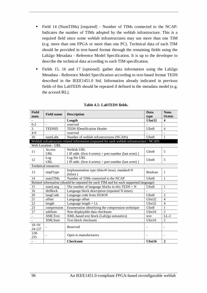
96 An IEEE1451.0-compliant FPGA-based reconfigurable weblab
Field 14 (NumTIMs) [required] - Number of TIMs connected to the NCAP:
Indicates the number of TIMs adopted by the weblab infrastructure. This is a
required field since some weblab infrastructures may use more than one TIM
(e.g. more than one FPGA or more than one PC). Technical data of each TIM
should be provided in text-based format through the remaining fields using the
Lab2go Metadata - Reference Model Specification. It is up to the developer to
describe the technical data according to each TIM specification.
Fields 15, 16 and 17 [optional]: gather data information using the Lab2go
Metadata - Reference Model Specification according to text-based format TEDS
described in the IEEE1451.0 Std. Information already indicated in previous
fields of this LabTEDS should be repeated if defined in the metadata model (e.g.
the accessURL).
Table 4.5: LabTEDS fields.
Field
num. Field name Description
Data
type
Num.
Octets
- Length UInt32 4
0-2 - reserved - -
3 TEDSID TEDS IDentification Header UInt8 4
4-9 reserved - -
10 numLabs Number of weblab infrastructures (NCAPs) UInt8 1
Weblab infrastructure related information (repeated for each weblab infrastructure / NCAP)
Web Location - URL
11 Access
URL
Weblab URL
[ IP addr. (first 4 octets) + port number (last octet) ] UInt8 5
12 Log
URL
Log file URL
[ IP addr. (first 4 octets) + port number (last octet) ] UInt8 5
Technical resources
13 implType Implementation type (thin≠0 (true), standard=0
(false) ) Boolean 1
14 numTIMs Number of TIMs connected to the NCAP UInt8 1
Related information (should be repeated for each TIM and for each supported language)
15 numLang The number of language blocks in this TEDS = N UInt8 1
16 dirBlock Language block description (repeated N times) - -
20 langCode Language code from ISO639 UInt8 2
21 offset Language offset UInt32 4
22 length Language length = LL UInt32 4
23 compression Enumeration identifying the compression technique UInt8 1
17 subSum Non-displayable data checksum UInt16 2
- XMLText XML-based text block (Lab2go semantics) text LL-2
- XMLSum Text block checksum UInt16 2
18-19/
24-127 - Reserved - -
128-255
- Open to manufacturers - -
- Checksum UInt16 2

Chapter 4: The IEEE1451.0 Std. as a smart framework for weblabs 97
This way, all weblab infrastructures and/or experiments can be described using
LabTEDSs. However, its adoption implies following a particular operational sequence
to enable their standard and distributed access.
4.6.3 Operational sequence
As illustrated in figure 4.15, the operational sequence includes three processes:
Registration: registers weblab infrastructures created according to the
IEEE1451.0 Std. The IP addresses and port numbers included in the accessURL
field of each LabTEDS are copied into the weblab server, registering the
infrastructures into the network.
Discovery: implements a discovery process, so users may find the appropriate
weblab they want to use, requesting a list of infrastructures and available
experiments already registered in the weblab server. This list may be
dynamically created using the NCAPDiscovery method. As described in the
following subsections, this method gets the URL of all registered weblab
infrastructures. Through their URL, each LabTEDS may be accessed using the
readLabTEDS method to create, for example, a webpage describing the
infrastructures and associated experiments.
Access: enables the access to weblab infrastructures to: i) control experiments;
ii) reconfigure weblab infrastructures with weblab modules (when they provide
this feature) and; iii) monitor all data transferred between students/teachers and
the infrastructures. This last sub-process is relevant for assessment purposes,
since all data transferred use methods for issuing standardized commands that
can be logged into a file for future analysis using, per example, intelligent
tutoring systems [130][139][140].
LabTEDS 1
Weblab infrastructuresWeblab server
registration
accessURL 2
LabTEDS 2
registration
accessURL 1
users
discovery
access...........
.......
Internet
Figure 4.15: Operational sequence for accessing weblab infrastructures.
All these processes are now described below using illustrative diagrams with the set
of new IEEE1451.0 HTTP methods.

98 An IEEE1451.0-compliant FPGA-based reconfigurable weblab
Registration
The registration process is automatically executed after connecting a weblab
infrastructure to the Internet. It uses the NCAPRegistration method to send the URL to
the weblab server, so it can create a map table with all registered weblabs. It is up to the
weblab server to periodically query if all infrastructures are still running, for example,
using a ping command to check if the destination IP address is available. If the response
to this command indicates the inexistence of the target IP, it means that the registered
infrastructure is not available anymore, and its URL should be deleted from the map
table, unregistering it. A weblab infrastructure may also unregister itself without being
disconnected from the Internet, using the same NCAPRegistration method. Figure 4.16
illustrates the proposed register/unregister process.
Weblabserver
Weblab infrastructure
NCAPRegister
ping
response to pingNCAPRegister
Register the infrastructure
Query the infrastructures is made periodicaly
The infrastructure may be unregistered depending on the ping command reply
Tim
e line
Infrastructure connected in the Internet
Figure 4.16: Process for registering/unregistering weblab infrastructures.
Discovery
The discovery process uses the NCAPDiscovery and ReadLabTEDS methods. The
NCAPDiscovery follows a similar approach provided by the TIMDiscovery and
TransducerDiscovery methods. It discovers the location of all registered infrastructures
(the NCAPs) by retrieving their IP addresses and port numbers provided by each
accessURL field of the associated LabTEDS. The ReadLabTEDS is much similar to the
methods included into the TEDS Manager API, namely to the ReadRawTEDS and
ReadTEDS92
. Using the URL retrieved by the NCAPDiscovery, the ReadLabTEDS reads
all information within each LabTEDS to create, for example, a webpage listing all
available infrastructures and associated experiments. Caching LabTEDSs is not
considered for the proposed architecture, since they should be always implemented in
the NCAP or remotely located. No redundant information is required, despite
developers may implement a mechanism to replicate LabTEDSs in more than one
location.
92 The IEEE1451.0 Std. adopted these two methods because it suggests caching the same TEDS
available in a TIM inside the NCAP, to improve speed and security by implementing redundant
information. The same ReadRawTEDS reads TEDSs available in TIMs, and the ReadTEDS may read
these same TEDSs only if they are not available in the NCAP, otherwise it reads the cached TEDSs.

Chapter 4: The IEEE1451.0 Std. as a smart framework for weblabs 99
The new NCAPDiscovery and ReadLabTEDS methods can be used by user-side or
weblab server-side applications. As illustrated in figure 4.17, in both situations the
NCAPDiscovery method retrieves the URL of a specific weblab infrastructure.
NCAPDiscovery
ReadLabTEDS
Weblabserver
Weblabinfrastructure
Tim
e line
NCAPDiscoveryIP address
port number
ReadLabTEDSresponseData
weblab access
users Weblabserver
Weblabinfrastructure
users
responseData
getWebpagewebpage
weblab access
a) User-side b) Weblab server-side
Figure 4.17: Using the NCAPDiscovery and ReadLabTEDS methods to access registered
weblab infrastructures.
In the first solution (user-side), users start sending the NCAPDiscovery to get an array
with the URLs of all registered infrastructures. Based on this information, users read all
features of each weblab infrastructure and/or experiments using the ReadLabTEDS.
Supported on the retrieved information from the LabTEDS, users create a list of all
available infrastructures and/or experiments.
In the second solution (weblab server-side), the NCAPDiscovery and ReadLabTEDS
are applied by the weblab server itself. An application constantly uses the
NCADiscovery method to get the URL of all registered infrastructures. Using the URLs
retrieved from that method, the weblab server consults each LabTEDS using the
ReadLabTEDS method, in the same way as described for the first solution. Unlike the
first solution, where all processing is made in the user-side, this second solution requires
a specific application inside the weblab server to handle the information retrieved from
each infrastructure.
Access (reconfiguration and logging)
The access process is divided in three sub-processes: i) control; ii) reconfiguration
and; iii) logging. The control sub-process is already covered by current methods
provided by the IEEE1451.0 HTTP API. It allows users to interact with the experiments
provided by the infrastructures. The other two (reconfiguration and logging) require
using new methods, as detailed in the following items.

100 An IEEE1451.0-compliant FPGA-based reconfigurable weblab
a) Reconfiguration
To remotely reconfigure weblabs, such as the ones using FPGA-based boards for
implementing the infrastructures, two new IEEE1451.0-HTTP API methods are
suggested, namely the ReadTIM and the WriteTIM. These methods are handled by the
NCAP and their adoption depends on the technological architecture of each TIM. While
the ReadTIM may be used without the previous methods, the WriteTIM should only be
applied after reading the technical characteristics of the target TIM. It is necessary to
use the ReadLabTEDS to get the technical data from the metadata defined in the XML
text-fields to evaluate if the TIM is capable of accommodating or accessing a specific
weblab module. Figure 4.18 illustrates the reconfiguration sub-process sequence using
the WriteTIM and ReadTIM methods.
b) Logging
The logging sub-process monitors users’ actions during their interaction with a
specific infrastructure. The objective is to provide a mechanism for assessment purposes
so teachers, eventually supported by automatic intelligent tutoring systems, may consult
a specific log file to evaluate students’ behaviour during the conduction of an
experiment. Field 12 of the LabTEDS (LogURL) indicates if a specific weblab
infrastructure has the logging activated by the URL of the log file. When active (i.e. the
LogURL is defined), all data used to access the infrastructure are logged into that file
located in the NCAP or remotely in the weblab server. The file, e.g. a database table,
should keep track of all data exchanged between the weblab infrastructure and the
users’ accessing devices according to the XML schema format presented in figure 4.18,
namely: the title of the experiment (expTitle), user’s identification (userID), a date
indicating when a specific action was applied (date), and the standardize methods
(method) with associated parameters (data).
The WriteLabTEDS activates the logging session writing the URL of the log file into
field 12 of the LabTEDS. Teachers may then read all students’ actions described in the
log file, using the ReadLogFile method. To clean or update that same log file (i.e. to
change its contents) teachers may use the WriteLogFile method. It is up to the developer
to establish some constrains on using both methods, since in most situations they should
only be accessible for teachers (e.g. for assessment purposes).
Despite the proposed architecture may contribute for the dissemination and wide
adoption of weblabs in education, the complexity of the IEEE1451.0 Std. may difficult
the development of their infrastructures. To overcome this situation, when less
demanding infrastructures are required to implement weblabs (e.g. weblab modules
implemented/accessed with a single TIM and/or implemented by technological devices
with limited resources), a single NCAP-TIM connection may be adopted using a thin
implementation of the IEEE1451.0 Std., following the first two solutions proposed in
section 4.5.

Chapter 4: The IEEE1451.0 Std. as a smart framework for weblabs 101
Weblabserver
Weblabinfrastructure
users
ReadLabTedsresponseData
(fields 20,21/tech. architecture)
get weblab module
WriteTIM
ReadTIMweblab module response
Tim
e line
Suggested log file XML schema
<?xml version="1.0"?>
<xs:schema xmlns:xs="http://www.w3.org/2001/XMLSchema">
xmlns:stml=http://grouper.ieee.org/groups/1451/0/1451HTTPAPI
<xs:element name="LogFile">
<xs:complexType>
<xs:sequence>
<xs:element name="expTitle" type=" stml: _String"/>
<xs:element name="userID" type=" stml: _String"/>
<xs:element name="date" type=" stml: timeInstance"/>
<xs:element name="method" type=" stml: _String"/>
<xs:element name="data" type=" stml: StringArray"/>
</xs:sequence>
</xs:complexType>
</xs:element>
</xs:schema>
Figure 4.18: Using the WriteTIM and ReadTIM for reconfiguring weblab infrastructures
and the suggested XML schema for the log file.
4.7. A thin implementation of the IEEE1451.0 Std. applied to
weblabs
According to the IEEE1451.0 Std., the NCAP and the TIM should be connected
through physical protocols (e.g. Bluetooth) following another IEEE1451.x Std. Despite
the standard intends to form the basis for future and previous IEEE1451.x Stds., some
of those are not yet compatible. Furthermore, the NCAP-TIM connection requires using
two additional APIs (Transducer services and Module communication) that imply
overloading developments and do not bring any added value for weblab infrastructures
that use single NCAP-TIM connections. These require a point-to-point interface that,
according to the IEEE1451.0 Std., requires using the IEEE1451.2 Std. However, this
standard is not yet compatible with the IEEE1451.0 Std. despite some suggestions [128]
and implementations [129], and it can overload the selected devices for implementing
the infrastructures. In these situations, removing both APIs from the reference model
does not limit the standardization advantages provided by the standard. The design of
all weblab modules still follows the same defined specifications, which includes their
design and access using standard commands and the HTTP API. The differences focus
on the way NCAP-TIM interface is internally managed. Although the plug&play
facility of the NCAP-TIM interface becomes dependent on development options, there
is the advantage of using an infrastructure more easily implemented with less
demanding technological devices, and not dependent on actualizations of other
IEEE1451.x Stds.
Therefore, a thin implementation can be implemented for infrastructures using point-
to-point NCAP-TIM connections using any type of physical protocol. This implies
removing the Transducer and Communication APIs of the layered structure, simplifying
the access to the commands by directly mapping them to the HTTP methods, as

102 An IEEE1451.0-compliant FPGA-based reconfigurable weblab
represented in figure 4.19. It is up to the NCAP to implement this mapping and to
handle the HTTP methods and their arguments, so they can be structured according to
the message structures defined in the IEEE1451.0 Std. and already presented in section
4.5. Table 4.6 presents the proposed mapping between the HTTP methods and the
commands, with all information detailed in annex H. It is important to notice that not all
methods are mapped, which means some are considered irrelevant for controlling the
TIM or they are exclusively handled in the NCAP side. However, this thin
implementation is just an alternative solution that, according to the proposed and
enhanced IEEE1451.0 architecture, must be indicated in field 13 (implType) of each
LabTEDS.
Module communcations API
Commands
Module communcations API
Transducer Services Interface API
HTTP APIApplications
NC
AP
TIM
......................
TCs
The interface depends exclusively on the adopted physical
connectionHTTP methods are mapped to
commands
Figure 4.19: A thin implementation of the IEEE1451.0 Std. layered structure.
Table 4.6: Mapping of HTTP APIs’ methods to TIM commands.
HTTP APIs and methods Commands Observation
Registration API No map -
NCAPRegistration (new)
Discovery API
No map - NCAPDiscovery (new),
TIMDiscovery and
TransducerDiscovery
Transducer Access API
ReadData, StartReadData,
MeasurementUpdate
SamplingMode and
ReadTCDSsegment Tables H.1, H.2
WriteData SamplingMode and
WriteTCDSsegment Table H.3
StartWriteData SamplingMode and
WriteTCDSsegment Table H.4
TEDS Manager API
ReadTEDS, ReadRawTEDS,
UpdateTEDSCache ReadTEDSsegment Tables H.5, H.6
WriteTEDS, WriteRawTEDS WriteTEDSsegment Table H.7
Read/WriteLabTEDS (new) No map -
Transducer Manager API
SendCommand, StartCommand
and CommandComplete Any command Tables H.8, H.9

Chapter 4: The IEEE1451.0 Std. as a smart framework for weblabs 103
Trigger or StartTrigger
ReadTEDSsegment and
SamplingMode and
TriggerCommand
Table H.10
Reconfiguration API No map -
WriteTIM or ReadTIM (new)
Log access API No map -
WriteLog or ReadLog (new)
4.8. Summary
This chapter described the main aspects of the IEEE1451.0 Std., which is
characterized by a well-defined layered architecture including specifications for
designing and interfacing weblab modules required for controlling and monitoring the
target experiments. Its reference model was presented, which includes one or more
TIMs remotely accessed through a NCAP for controlling the TCs implementing or
binding weblab modules. Associated characteristics were also detailed, such as the
operation modes, accessing mechanisms and commands to control the TIM and each
TC, the available APIs for the NCAP-TIM interface and for their remote access, and in
particular the set of defined TEDSs, as well as their internal structures. Supported on
features defined by the IEEE1451.0 Std., this chapter suggested some compliant
infrastructures, which can be part of a generic and enhanced architecture to facilitate the
widespread sharing of weblabs through the educational community. The proposed
enhancements involve the use of a new TEDS, named LabTEDS, for providing generic
information about the infrastructures and associated experiments, and the use of new
HTTP-based interfaces and methods for managing weblab resources. Finally, this
chapter emphasized the possibility of simplifying the layered architecture of the
standard, through a thin implementation, for facilitating the design of weblab
infrastructures compatible with the proposed enhanced architecture.
Next chapter presents a prototype of this thin implementation developed using FPGA
technology to enable its remote access and reconfiguration.

104 An IEEE1451.0-compliant FPGA-based reconfigurable weblab

Chapter 5: A weblab implementation supported by FPGA-based boards 105
Chapter 5
A weblab implementation supported by
FPGA-based boards
The features of the IEEE1451.0 Std., suggested extensions and proposed
architectures establish the framework that supports the IEEE1451.0-compliant and
FPGA-based weblab prototype described in this chapter. The overall weblab
architecture and the underlying infrastructure able to be reconfigured with different
weblab modules controlled/monitored according to the IEEE1451.0 Std., are described
in the following sections. A special attention is given to the infrastructure designed
according to the thin implementation of the IEEE1451.0 Std. reference model.
Characteristics and functionalities provided by an IEEE1451.0-compliant module are
also described, since it enables the interface and the standard access to different and
compatible weblab modules embedded in an FPGA-based infrastructure. This access is
further explored, by presenting the provided accessing mechanisms to the weblab. The
chapter ends by describing a tool that enables reconfiguring the weblab infrastructure
with the modules required for conducting remote experiments, using IEEE1451.0
commands.

106 An IEEE1451.0-compliant FPGA-based reconfigurable weblab

Chapter 5: A weblab implementation supported by FPGA-based boards 107
5.1. Overall architecture: weblab server and underlying
infrastructure
The overall architecture proposed follows the same generic approach of a traditional
weblab, comprising an infrastructure supported by a weblab server. These are connected
to the Internet, and each one is able to provide the services required for conducting
remote experiments, as part of an engineering course. The weblab server is capable of
using solutions already developed, such as the iLabs architecture93
for users’ access
management, and the LiLa portal94
to accommodate pedagogical contents. However, the
developed prototype does not integrate any of them. Additionally, the different
scenarios suggested in the previous chapter for developing weblab architectures based
on extensions proposed for the IEEE1451.0 Std., can be also easily applied in future
designs. With few changes, the operational sequence described in section 4.6.2, namely
the processes of registering, discovering and accessing the infrastructures, can be latter
implemented to disseminate the weblabs and share the associated experiments through
the educational community. The WriteTIM method of the suggested reconfiguration API
was adopted for reconfiguring the infrastructure. It is precisely the way this
infrastructure can be reconfigured and accessed the focus of the developed weblab
prototype, to illustrate the usage of the IEEE1451.0 Std. supported by FPGA technology
for designing reconfigurable weblabs.
The prototype follows an architecture that provides an IEEE1451.0 standard access
to the underlying infrastructure and to the adopted weblab modules. It enables
reconfiguring those modules without changing the hardware platform that forms the
infrastructure. Instead of using traditional instrumentation to interact with the target
experiments, the architecture adopts embedded modules. These are described through
HDL files according to the IEEE1451.0 Std., able to be synthesized to FPGAs, which
form the core of the infrastructure.
As illustrated in figure 5.1 and figure 5.2, the architecture is supported by a weblab
server and by an underlying infrastructure designed according to the NCAP-TIM
reference model. Among all the possible solutions described in section 4.5, the
prototype adopts a single NCAP-TIM connection and uses the proposed thin
implementation that establishes the direct mapping between the methods of the
IEEE1451.0-HTTP API and the commands implemented in the TIM. The weblab server
runs in a standard PC acting as an HTTP web server. It integrates a Reconfiguration
Tool (RecTool) to create a bitstream file that defines the so-called weblab project. This
weblab project comprises the weblab modules required to control/monitor the target
experiments that will be reconfigured in the infrastructure. This infrastructure adopts an
NCAP-TIM connection using an hybrid solution. A thin computer acting as a light
93 http://ilab.mit.edu/, http://ilabcentral.org/ 94 http://www.lila-project.org/

108 An IEEE1451.0-compliant FPGA-based reconfigurable weblab
HTTP web server implements the NCAP. The TIM, where all modules are embedded
and accessed using TCs, is implemented in an FPGA-based board.
NCAP
Web server
WWW
Users
Target
experimentIE
EE
1451.0
H
TT
P A
PI
Reconfiguration
Tool (RecTool)
Weblab server
Weblab infrastructure
IEEE1451.0
-Module
Weblab module
.........
TC
TC
TC
TIM FPGA-based board
TEDSTEDS
Weblab module
Weblab module
IEE
E1451.0
C
om
mands
weblab project
Section 5.2
Section 5.2.3
Section 5.3
Section 5.2.2
Section 5.4
Section 5.2.1
Section 5.5
Section 5.1
Figure 5.1: Bock diagrams of the implemented weblab architecture.
Weblab server
NCAP(thin computer)
TIM(FPGA-based board)
Target experiment(example)
Figure 5.2: Picture of the implemented weblab architecture.
To create the weblab project, users directly interact with the weblab server for
accessing the RecTool. They may select a set of files describing each weblab module
(provided by the weblab server) and synthesize them with a predefined IEEE1451.0-
compliant module described through HDL files, which is already available in the
weblab server as a part of the RecTool. Through a reconfiguration process, that will be
described in chapter 6, its HDL files are automatically redefined (connections,
associated TEDSs, etc.) to bind the selected weblab modules, and latter synthesized to
create a bitstream file describing the weblab project used to reconfigure the FPGA-
based board. This way, all weblab modules selected for conducting a particular
experiment are accessed and controlled according to the IEEE1451.0 Std. using
methods from the IEEE1451.0-HTTP API, since all features provided by the weblab
modules are compliant with the standard.
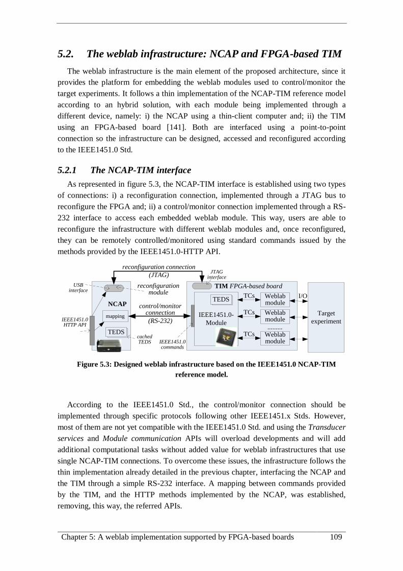
Chapter 5: A weblab implementation supported by FPGA-based boards 109
5.2. The weblab infrastructure: NCAP and FPGA-based TIM
The weblab infrastructure is the main element of the proposed architecture, since it
provides the platform for embedding the weblab modules used to control/monitor the
target experiments. It follows a thin implementation of the NCAP-TIM reference model
according to an hybrid solution, with each module being implemented through a
different device, namely: i) the NCAP using a thin-client computer and; ii) the TIM
using an FPGA-based board [141]. Both are interfaced using a point-to-point
connection so the infrastructure can be designed, accessed and reconfigured according
to the IEEE1451.0 Std.
5.2.1 The NCAP-TIM interface
As represented in figure 5.3, the NCAP-TIM interface is established using two types
of connections: i) a reconfiguration connection, implemented through a JTAG bus to
reconfigure the FPGA and; ii) a control/monitor connection implemented through a RS-
232 interface to access each embedded weblab module. This way, users are able to
reconfigure the infrastructure with different weblab modules and, once reconfigured,
they can be remotely controlled/monitored using standard commands issued by the
methods provided by the IEEE1451.0-HTTP API.
NCAP
IEEE1451.0-
Module
Weblab module
.........
TCs
TIM FPGA-based board
TEDSTEDS
IEEE1451.0 HTTP API
Weblab module
Weblab moduleIEEE1451.0
commands
reconfiguration module
reconfiguration connection
(JTAG)
control/monitor connection
(RS-232)
JTAG interface
USB interface
mapping
TEDSTEDScached TEDS
Target
experiment
TCs
TCs
I/O
Figure 5.3: Designed weblab infrastructure based on the IEEE1451.0 NCAP-TIM
reference model.
According to the IEEE1451.0 Std., the control/monitor connection should be
implemented through specific protocols following other IEEE1451.x Stds. However,
most of them are not yet compatible with the IEEE1451.0 Std. and using the Transducer
services and Module communication APIs will overload developments and will add
additional computational tasks without added value for weblab infrastructures that use
single NCAP-TIM connections. To overcome these issues, the infrastructure follows the
thin implementation already detailed in the previous chapter, interfacing the NCAP and
the TIM through a simple RS-232 interface. A mapping between commands provided
by the TIM, and the HTTP methods implemented by the NCAP, was established,
removing, this way, the referred APIs.

110 An IEEE1451.0-compliant FPGA-based reconfigurable weblab
Since the IEEE1451.0 Std. does not consider the reconfiguration issue proposed and
implemented in the current architecture, no mapping was required for using the
suggested WriteTIM method. For its adoption, the reconfiguration connection uses a
single JTAG bus, but if more than one TIM were connected to the NCAP, several
reconfiguration connections should be implemented (one for each TIM). This particular
implementation uses an USB–JTAG cable95
controlled by a reconfiguration module
implemented by the UrJTAG software96
running in the NCAP.
5.2.2 The NCAP
The NCAP was implemented in a thin-client computer from Epatec97
illustrated in
figure 5.4. It provides the remote access to the TIM through the IEEE1451.0-HTTP API
supported by a software package that implements the services of each method, the
mapping mechanism between methods and commands, a cached TEDS for facilitating
the management and the access to the infrastructure and to the embedded modules, and
the physical connections. The software package is portable and able to be recompiled
for different Linux distributions according to instructions defined in a makefile. It is
denominated as NCAP-package and comprises a C-CGI (C Common Gateway
Interface) application. Integrated in the Apache HTTP web server98
installed in the
Ubuntu operational system99
, it allows remote users to use IEEE1451.0-HTTP methods
to control the TIM and, therefore, every reconfigured weblab module. As represented in
figure 5.5, the package is organized in a set of directories each with its specific
relevance, namely the 1451 directory and the cgi-bin directory. The 1451 directory
comprises a set of symbolic links to access a server.cgi file (created after every
compilation) to handle IEEE1451.0-HTTP methods applied according to the message
format http://.../1451/command. The cgi-bin directory contains all files and directories
used by the NCAP-package. It comprises a set of source (*.c), header (*.h) and object
(*.o) files, integrating all the interfaces defined in the IEEE1451.0-HTTP API (e.g.
IEEE1451TransducerManagerAPI.c), whose accesses are made by the server.cgi file
used to manage all users’ requests. The NCAP-package also integrates the utils.c file
that provides some useful conversion functions, and a file named serial.c to control the
NCAP RS-232 interface. Besides all these files, the package has two other important
directories: the teds directory to keep cached-TEDSs, which according to the
IEEE1451.0 Std. may represent copies or updates of TEDSs defined within the TIM,
and the urjtag directory containing the files and applications required for reconfiguring
the TIM. This last aspect is not considered by the IEEE1451.0 Std. but, as already
suggested, current NCAP-package implements the WriteTIM method integrated in the
new Reconfiguration API.
95 Mini Altera FPGA CPLD USB Blaster programmer JTAG. 96 http://urjtag.org/ 97 http://www.epatec.de/en/home/ 98 http://httpd.apache.org/ 99 http://www.ubuntu.com/server

Chapter 5: A weblab implementation supported by FPGA-based boards 111
Mini Altera FPGA CPLD USB Blaster programmer JTAG
Reconfiguration connection (USB)
Back panel
Control/monitoring connection (RS-232)
Ethernet connection
control/monitor connection (RS-232)
Figure 5.4: Photograph of the NCAP implemented using a thin-client computer.
Symbolic links to the implemented methods in the *.c files of the cgi-bin folder using the paths of the HTTP message format specified by the standard (http://.../1451/command)
cgi-bin
1451
Cached TEDSs generated by the writeTEDS and updateTEDScache commands and read by readTEDS command. All TEDSs are in the binary format and use the following format: t_tc_c_.teds, [t- TIM number; tc- TC number; c- TEDS codeID].
teds
UrJTAG
Installation of the UrJTAG software and other files used for sending to the FPGA the binary file of the weblab project using the JTAG interface of the reconfiguration connection.
Files that implement the different APIs of the IEEE1451.0-HTTP API [C source code files (*.c), header files (*.h), and the object files generated after the compilation of the NCAP-package (*.o)].
Makefile used to compile the entire NCAP-package.
Files for supporting the serial communication (serial.c) the access to the server (server.c) and extra services (util.c).
HTML forms with methods of the IEEE1451.0-HTTP API (used to verify the correct operation of the weblab), and a supporting page with mapped error codes (errorCODES.html).
Figure 5.5: NCAP-package folder organization.
Through a simple web browser users can access the services provided by the NCAP-
package to control/monitor the embedded weblab modules through the associated TCs.
They are able to issue IEEE1451.0 commands through the methods of the IEEE1451.0-
HTTP API using a thin-client approach, i.e. without requiring the installation of any
additional software in their accessing devices. A simple web browser with the HTTP

112 An IEEE1451.0-compliant FPGA-based reconfigurable weblab
protocol active is the only requirement for accessing the infrastructure, which may
facilitate the development of weblab interfaces using any type of software language. For
validation purposes, the package also provides a set of HTML forms that enables users
to issue IEEE1451.0 commands through the HTTP API, and a supporting webpage with
the implemented error codes mapped from the errors generated by the TIM.
Annex I presents the error codes that may be retrieved from current NCAP
implementation.
Since the infrastructure follows a thin implementation, the Args and Util packages
defined by the IEEE1451.0 Std. were not implemented. Some of their services, namely
data conversion and manipulation, and the encoding and decoding of the message
structures, were implemented in the C source files of the implemented APIs using some
functions of the utils.c file.
5.2.3 The TIM
The TIM was implemented in an FPGA-based board from Xilinx with a XC3S1600E
Spartan 3E FPGA 100
illustrated in figure 5.6. It accommodates the weblab project with
all the weblab modules required for accessing the target experiments. The decision for a
solution based on an FPGA-based board was essentially supported on four main
reasons: i) it integrates several digital and analog I/O interfaces to access the target
experiments; ii) it can use weblab modules described through HDL files, which make
them easily shared by different infrastructures; iii) it can run those modules in parallel
like in a laboratory that uses traditional instrumentation and; iv) it is able to be
reconfigured, enabling to change the entire functionality of the weblab infrastructure
without replacing the hardware platform required to access an experiment. Additionally,
supported by the considerations presented in section 3.4, the implemented weblab
architecture adopts a solution based on a total reconfiguration of the FPGA. This means
that every change in the infrastructure (e.g. swapping a weblab module) requires
creating an entirely new bitstream file of the weblab project using the RecTool. This
option led to adopt FPGAs with total reconfiguration capability, rather than partial
reconfiguration that would increase the associated costs of the infrastructure (FPGAs
with partial reconfiguration are usually more expensive) and would limit the freedom of
choice of an FPGA, since not all provide the partial reconfiguration capability.
Internally, the TIM integrates a generic IEEE1451.0-compliant module with different
weblab modules able to be accessed and controlled according to the IEEE1451.0 Std.
This approach is versatile since it allows binding several weblab modules able to control
using standard commands, and it is reusable because the IEEE1451.0-compliant module
and the weblab modules are described using standard HDL files able to embed into
different types of FPGAs.
100 http://www.xilinx.com/products/boards-and-kits/

Chapter 5: A weblab implementation supported by FPGA-based boards 113
FPGAI/O to the target experiment(s)
reconfiguration connection (JTAG)
control/monitor connection (RS-232)
Figure 5.6: Picture of the FPGA-based board where the TIM is implemented.
5.3. An IEEE1451.0-compliant module for binding weblab
modules
The IEEE1451.0-compliant module, named as IEEE1451.0-Module, is embedded in
the FPGA that implements the TIM. This module implements IEEE1451.0 Std. features
to control/monitor the weblab modules bound through a reconfiguration process. To
simplify and reduce the FPGA resources required to implement the IEEE1451.0-
Module, without hampering its operation, current solution does not implement group
addresses and most of the optional commands. It enables the use of a single sampling
mode, and only commanded transmission mode is available, which requires the use of
the Read/WriteTCDSsegment IEEE1451.0 commands to transfer data between the TIM
and the NCAP, and therefore to the remote users.
The TCs operate as interfaces to establish the communication between the
IEEE1451.0-Module and the parameters able to control in the weblab modules. The
way these TCs are accessed is exactly the same as described by the standard, operating
according to the definition of TEDSs. The DSs are not exclusively associated to a single
TC, but rather they should be seen as internal buffers within the weblab modules able to
be accessed by one or more TCs. All these implementations are in accordance with the
IEEE1451.0 Std. and allow defining a versatile architecture to develop and bind the
modules to the IEEE1451.0-Module.
The weblab modules, which are described using the Verilog HDL, can be of any type
depending on the requirements posed by the target experiment, such as: Function
Generators, Oscilloscopes, Step-motor controllers, and others able to be embedded into

114 An IEEE1451.0-compliant FPGA-based reconfigurable weblab
an FPGA-based board, like embedded instruments. They must be compatible with the
IEEE1451.0-Module, so they can be controlled by the TCs using IEEE1451.0
commands to interact with the parameters and associated DSs, according to
specifications defined in TEDSs.
The IEEE1451.0-Module comprises a specific architecture described through Verilog
HDL files. It is able of being redefined for binding compatible weblab modules,
enabling their standard access. The modules are bind according to a specific
reconfiguration process handled by the RecTool, and synthesised to any type of FPGA.
As represented in figure 5.7, the architecture of the IEEE1451.0-Module comprises four
submodules. The core is the Decoder/Controller Module (DCM) that manages the
behaviour of the whole module, decodes and generates commands from/to an UART
Module (UART-M). This interfaces the NCAP using an RS-232 interface, and
implements mechanisms to guarantee that the transferred data is in accordance with
command and reply messages structures defined in the IEEE1451.0 Std. To
control/monitor the behaviour of each weblab module, the DCM accesses two other
modules: i) a TEDS Module (TEDS-M), that internally implements all required TEDSs,
and; ii) the Status/States Module (SSM), that integrates internal memories to keep the
state and status of all TCs and of the TIM. Both modules are supported by internal
controllers that enable the DCM to read, write or update the TEDSs and the status and
state memories. Errors generated by these internal modules or by a particular weblab
module are handled by the DCM.
TIM - FPGA
access(RS-232)
UART-
M
TEDS-M
SSM
......
Decoder Controller Module
(DCM)
IEEE1451.0-Module
TC
Target
experimentNCAP
Weblab module Weblab module
FPGA-based board interfaces
(re)configuration(JTAG)
I/O
Figure 5.7: Overview of the IEEE1451.0-compliant module (IEEE1451.0-Module).
As already referred, besides the access and the control of the weblab modules, the
IEEE1451.0-Module is capable of being redefined and reconfigured in the
infrastructure. This was one of the main challenges for implementing the reconfigurable
infrastructure, namely the definition of an internal architecture capable of connecting
the weblab modules to the DCM. The reconfiguration of this weblab requires redefining
all internal modules of the IEEE1451.0-Module, in particular the DCM by adding or
removing TCs, the TEDS-M that should gather the required TEDSs, and the SSM to
keep the states and the status of the TIM and of each TC. The UART-M is the only
module that is not changed during the reconfiguration process since its main task focus

Chapter 5: A weblab implementation supported by FPGA-based boards 115
on receiving and sending IEEE1451.0 commands. This process is entirely handled by
the RecTool that is responsible of redesigning the entire weblab project and sending it
to the TIM to reconfigure the FPGA using a JTAG interface.
5.4. Weblab accessing mechanisms
The use of the IEEE1451.0 Std. for designing weblab infrastructures aims to
standardize the design and the access to the weblab modules. The standard defines a
layered architecture divided into several APIs that facilitates the access to TCs and to
TIMs using standard commands. These commands are implemented in the TIM and
they are issued according to message structures. Current implementation of the
IEEE1451.0-Module recognizes most of the commands that enable
controlling/monitoring the TCs/TIMs and, therefore, the attached weblab modules. Each
command is issued to the TIM through the RS-232 interface. The UART-M is
responsible for receiving and verifying if the received command messages structures are
in accordance with the IEEE1451.0 Std. The decoding is made by the DCM that,
according to the selected command, will manage the entire IEEE1451.0-Module for
controlling each weblab module. It also generates the associated replies, defining reply
messages structures to be transmitted to the NCAP using the same RS-232 interface.
According to the IEEE1451.0 Std., the construction of message structures should be
made in the Communication API that is the responsible for managing the NCAP-TIM
connections. Since current architecture follows a thin implementation, when the NCAP
receives remote commands through the HTTP methods, they are decoded and directly
mapped to command messages structures recognized and sent to the TIM using the RS-
232 interface, as depicted in figure 5.8. The same process is followed when replies are
generated by the TIM. In this situation, the NCAP receives reply messages structures
through the same RS-232 interface, decodes them, and defines the reply messages,
whose formats (XML, text or HTML) are previously indicated in a parameter of the
HTTP methods that originated those replies. Despite the TIM may also generate TIM-
initiated messages, currently the NCAP does not handle this type of messages, i.e. it is
not able to decode and generate HTTP messages caused by TIM-initiated messages.
TIM - FPGA
UART-Mcommand structure validation
& reply structure definition
......
DCM(decode & control)
IEEE1451.0-Module
HTTP method
command message
reply messagestructure
decodingHTTP reply
generation
mappingCommand(s)
structure definition
command messagestructure
WWW
Users
HTTP reply
NCAP
Figure 5.8: NCAP-TIM accessing mechanism.

116 An IEEE1451.0-compliant FPGA-based reconfigurable weblab
The well-defined and standard division between the message structures of the TIM
and the message formats of the NCAP guarantees a clear separation between these two
modules. The adopted thin implementation of the IEEE1451.0 Std. does not adopt the
APIs used for interfacing the NCAP and TIM, but it stills guarantees a plug&play
facility between both, since they follow the message formats defined by the IEEE1451.0
Std. This means that NCAPs and TIMs that follow this same implementation may also
be easily interfaced without further developments. The collaboration during the
developments can be therefore guaranteed. Developers that follow the proposed thin
implementation, in particular the described accessing mechanisms, may split their work
by developing independently the NCAP, the TIM and the different weblab modules that
should be compatible with the IEEE1451.0-compliant module.
During developments, the verification of the TIM operation independently of the
NCAP was facilitated, since they can be independently accessed. Previously
reconfigured with a simple I/O weblab module (described in chapter 6) compatible with
the IEEE1451.0-Module, the TIM was controlled using IEEE1451.0 commands and
monitored through the associated replies101
. As represented in figure 5.9, several
commands were issued and the replies observed, proving that the TIM and the
associated weblab module operation are in accordance with the IEEE1451.0 Std.
TC number
Command (class + function) - ReadTEDSsegment
length
TEDS access ID code
offset
Reply error
message
Reply
message
success
length
TEDS contents
Figure 5.9: Example of commands sent to the TIM reconfigured with an I/O weblab
module using the Comm Operator Pal serial port tool.
101 This was achieved by using a simple PC running a serial communication tool named Comm
Operator Pal attached to the FPGA-based board through the RS-232 interface
(http://www.serialporttool.com/CommPalInfo.htm).

Chapter 5: A weblab implementation supported by FPGA-based boards 117
Therefore, the TIM can be attached to any type of device able to understand
IEEE1451.0 commands. Enriched software applications can then be developed for
controlling the weblab, extending its application to different solutions and domains that
require a local or a remote control through the web. This was precisely the objective of
using the NCAP. Despite the thin implementation of the NCAP-TIM reference model,
the software package developed for the NCAP permits accessing the IEEE1451.0
commands using the HTTP-IEEE1451.0 API. Moreover, as already referred, it provides
a set of HTML pages to facilitate issuing those commands using the different methods
provided by the API allowing, this way, to verify the correct operation of the
infrastructure when remotely controlled. Figure 5.10 exemplifies the use of the
ReadTEDS command, which accesses the MD-TEDS of a weblab module connected to
the IEEE1451.0-Module using the TC number 3, and presents the associated reply in
XML format.
Another possibility for accessing the TIM is provided by the Reconfiguration API
also implemented in the NCAP. In the current implementation, was adopted the
WriteTIM method to send the bitstream file (describing the weblab project) to the
reconfiguration module installed in the NCAP. This module, supported by the UrJTAG
software, sends the file to the FPGA-based board reconfiguring the infrastructure. In
this situation, users do not have a direct interaction with the WriteTIM method since this
is issued by the RecTool. The advantage of using the WriteTIM and the ReadTIM
methods is the possibility they offer for providing a standard access to the NCAP for
reconfiguring the infrastructure. This means that if a different RecTool were created,
developers should take into consideration that reconfiguring the infrastructure would
require using the methods provided by the Reconfiguration API, which will incentivize
the collaboration during developments.
b) XML format reply a) command
Figure 5.10: Example of a ReadTEDS command and the associated reply in XML format
issued using the IEEE1451.0-HTTP API.

118 An IEEE1451.0-compliant FPGA-based reconfigurable weblab
5.5. The weblab reconfiguration tool
The RecTool enables to reconfigure the weblab infrastructure with different weblab
modules, changing it according to the requirements posed by the target experiments.
This tool is accessed through an interface using a web browser able to parse HTML
tags, without any specific plug-ins or software tools installed in the users’ accessing
device. The reconfiguration of the infrastructure is much dependent on the redefinition
of the internal architecture of the IEEE1451.0-Module that is pre-defined and available
in the weblab server. The files describing these modules are included in the weblab
Server File System (WSFS) of the RecTool software, providing all the applications
required to redefine the IEEE1451.0-Module to bind the weblab modules. Although a
reconfiguration process is automatically implemented by the RecTool, users should
follow a specific sequence that includes: i) selecting the weblab modules; ii) defining
their connections within the infrastructure; iii) building and synthesizing the weblab
project and; iv) reconfiguring the infrastructure.
The interaction with the RecTool is performed using the web interface illustrated in
figure 5.11. It is divided in three main sections, enabling users to control all the
reconfiguration process:
upload - Allows uploading configuration and project files to create the weblab
project, and/or files, already synthesized by this same RecTool, to reconfigure
the infrastructure;
information - All feedback actions made by the users are displayed in this
section, which also presents the current weblab server state, namely its current
time and if it is busy synthesizing a weblab project;
panels - This section is divided in three panels: i) build panel, which presents all
files required to build the weblab project and enables users to start the building
process; ii) reconfiguration panel, which enables users to start the synthesis and
the reconfiguration processes and has all synthesized files used to reconfigure
the FPGA and; iii) reports panel, which provides reports generated during the
users’ interaction with the RecTool.
The WSFS provides a space shared by different users for generic files and for the
applications used in the RecTool, and another space reserved for each user, so they can
store their own files. Those files may be divided into two groups: i) files used for
building a weblab project (available in the build panel) and; ii) files generated by the
RecTool, available in the reconfiguration and reports panels, that have in their names
the date and time of their creation so users may understand the action(s) that originated
them.

Chapter 5: A weblab implementation supported by FPGA-based boards 119
pa
ne
lsin
form
ati
on
up
loa
d
Figure 5.11: Web interface of the weblab reconfiguration tool.
The build panel has two subgroups of files for building the weblab project:
configuration files (*.conf) - Text files containing all rules for redefining the
weblab project, namely to check consistency, generate and interface the project
files into the IEEE1451.0-Module and to specify all configurations required for
binding the weblab modules to that same infrastructure;

120 An IEEE1451.0-compliant FPGA-based reconfigurable weblab
project files (*.v/vh/map/teds/ucf) - Comprise five types of files required for
building the weblab project: i) Verilog HDL files with the design of each weblab
module (*.v); ii) Verilog HDL files with the interface for binding those modules
to the IEEE1451.0-Module (*.vh); iii) binary files describing the TEDSs used by
the IEEE1451.0-Module to control and monitor the weblab modules (*.teds); iv)
a binary file to map those same TEDSs into the IEEE1451.0-Module (*.map)
and; v) one file to describe the pinout used by the FPGA-based board (*.ucf).
The reconfiguration panel provides two types of files generated by the weblab server
for reconfiguring the FPGA, namely:
bitstream files (*.bit) - Contain the binary code used to reconfigure the FPGA,
and/or;
Simple Vector Format (SVF) files (*.svf) - Contain boundary scan vectors to
send the same binary code available in the bitstream files to an FPGA using a
JTAG interface.
The reports panel may provide five types of report files (*.rep) generated during the
interaction with the RecTool:
Bbind_date.rep - Describes the interface established by the weblab modules with
the IEEE1451.0-Module;
Bteds_date.rep - Provides information about the TEDSs’ consistency check,
generation of HDL files with TEDSs’ contents and their interface with the
IEEE1451.0-Module;
Syn_date.rep - Reports the results of the weblab project synthesis;
Svf_date.rep - Indicates if the *.svf file was successfully created;
Reconf_date.rep - Reports the final result of the reconfiguration process,
indicating if it was successful.
The inherent complexity of the reconfiguration process and of the modules that form
the weblab infrastructure will be detailed in the following chapter. It will focus on the
structure and functionalities of the IEEE1451.0-compliant module, layout and interfaces
for binding and designing the weblab modules, and on the implementation and
utilization of the RecTool.

Chapter 5: A weblab implementation supported by FPGA-based boards 121
5.6. Summary
Supported by the features described in the IEEE1451.0 Std. that involves the use of a
well-defined reference model, the previous chapter suggested a thin implementation for
designing standard based weblabs. Since the suggested implementation does not hamper
the standard access to weblabs, it was considered an interesting solution for verifying
the advantages of using the IEEE1451.0 Std. for designing reconfigurable weblabs. This
chapter presented an implementation of a reconfigurable weblab based on that thin
implementation using FPGA-based boards for designing the underlying infrastructure.
For its reconfiguration, one of the extensions proposed for the IEEE1451.0 Std., namely
the use of the WriteTIM method, was adopted. The overall weblab architecture and
functionalities were presented, namely the possibility of reconfiguring the infrastructure
with different weblab modules able to be controlled/monitored according to the
IEEE1451.0 Std. The NCAP-TIM reference model and their connections were detailed,
explaining the functionalities provided by each. It was provided an overview of the
IEEE1451.0-complaint module and of its internal structure, since this is the main
element that enables the reconfiguration of the weblab by the ability it has of being
automatically redefined for binding the weblab modules selected for the conduction of a
given remote experiment. Before presenting the functionalities of the RecTool and its
interface, mechanisms for accessing the weblab were presented, emphasizing the way
IEEE1451.0 commands can be applied to the weblab for controlling/monitoring the
weblab modules and the entire infrastructure. Since the redefinition of the weblab is
automatically processed using the RecTool installed in the weblab server, a generic
overview of its functionalities was presented, leaving the other details to the following
chapter.

122 An IEEE1451.0-compliant FPGA-based reconfigurable weblab

Chapter 6: The weblab reconfigurable framework 123
Chapter 6
The weblab reconfigurable framework
The two previous chapters described the IEEE1451.0 Std. and presented a compliant-
weblab prototype, whose infrastructure is supported by an FPGA-based board able to
accommodate weblab modules required to conduct remote experiments.
This chapter details the reconfigurable framework provided by the designed weblab
prototype, describing all the involved resources and tools required for reconfiguring the
infrastructure with the weblab modules. The different interactions among those
resources and tools, and the role of students, teachers, technicians and developers in the
reconfiguration process, is also referred. Since the reconfiguration capability is mainly
provided by the IEEE1451.0-compliant module configured in the FPGA, a particular
attention is given to its structure and functionality, and to the layout and interface of
compatible weblab modules. The IEEE1451.0-compliant module is detailed, namely its
internal structure that includes a set of modules, whose capabilities of being
automatically redefined for binding the weblab modules during a reconfiguration
process are highlighted. The weblab modules are also detailed, in particular their layout
and interfaces. The chapter ends by presenting the reconfiguration process, namely the
functional and technical details of the Reconfiguration Tool (RecTool).

124 An IEEE1451.0-compliant FPGA-based reconfigurable weblab

Chapter 6: The weblab reconfigurable framework 125
6.1. Involved resources and tools
Besides the adoption of the IEEE1451.0 Std. for the standard access and design of
weblabs, the 2nd
innovation proposed in this work focus on the capability for
reconfiguring the weblab infrastructures [142]. The weblab modules are able to be
reconfigured in the infrastructure, overcoming the usual limitations of today’s weblabs
that only allow setting up connections among traditional instruments and the target
experiments. By using a reconfigurable framework, students, teachers and technicians
can select weblab modules required to conduct a particular experiment and include them
into the weblab infrastructure, as done in a traditional laboratory by selecting the
instruments and connecting them to the target experiments. Additionally, the adoption
of weblab modules described through HDL files according to the IEEE1451.0 Std.
provides an added-value to common weblabs, since those modules can be easily
replicated and shared, as previously referred in this thesis.
As illustrated in the conceptual diagram of figure 6.1, the reconfigurable framework
comprises different resources and tools implying the interaction of two main groups of
human actors: i) students, teachers and technicians, to reconfigure the weblab with
different weblab modules and; ii) developers, whose tasks focus on designing
compatible weblab modules able to be shared by the educational community when
adopting similar weblab architectures.
Weblab server
Weblab modules
Students,
teachers,
technicians
interact
Weblab modulesWeblab
modules
select
creates the weblab project
uploaded
provided by
web interface
RecTool
Weblab
infrastructure
reconfigures
Developersdesign
IEEE1451.0-compliant module(redefined by internal Bind and Config software modules according to a set of rules specified to
bind the selected weblab modules)
sends the weblab project
NCAP + TIM
manage the reconfiguration process
FPGA-based board
configuration file
uploadeddefine rules
Figure 6.1: Conceptual diagram with tools, resources and the human actors involved in
the reconfiguration process.
The RecTool provided by the weblab server is responsible for creating the so-called
weblab project, which is the bitstream file used to reconfigure the TIM of the
infrastructure implemented by the FPGA-based board. The weblab project is the result
of a reconfiguration process that involves the selection of the weblab modules required
126 An IEEE1451.0-compliant FPGA-based reconfigurable weblab
to reconfigure the infrastructure. This process is essentially made by students, teachers
or technicians to design a workbench to conduct the remote experiments. They select a
set of files (HDL files and binary files with the TEDSs) describing the weblab modules,
and bind them to a generic IEEE1451.0-compliant module predefined and available in
the RecTool. This process implies an interaction with a web interface provided by the
RecTool that requires the definition of a configuration file with a set of rules for
reconfiguring the weblab infrastructure. According to those rules, two software modules
named Bind and Config (part of the RecTool) redefines the IEEE1451.0-compliant
module, entirely described through Verilog HDL files, and bind the selected weblab
modules. This process is entirely transparent to students, teachers and technicians, since
they just need to interact with the RecTool interface without describing any module
used to create the weblab project that is sent to the FPGA-based board for reconfiguring
the infrastructure.
Since the idealized and implemented architecture for reconfiguring weblabs seeks to
improve collaboration among the educational community by sharing different weblab
modules, these should be designed to be compatible with the IEEE1451.0-compliant
module available in the RecTool. These are precisely the tasks for the involved
developers. They should focus their efforts on designing the weblab modules according
to a set of specifications, so they can be easily shared and bound to weblab
infrastructures similar to the one described in this thesis. Therefore, it is important to
understand the structure and functionalities provided by the IEEE1451.0-compliant
module, so it may be redefined to connect compatible weblab modules. Additionally,
the design of those modules should follow a particular layout and interface, which is
mainly implemented by the IEEE1451.0-compliant module redefined according to the
reconfiguration process.
6.2. Structure and functionality of the IEEE1451.0-compliant
module
The IEEE1451.0-compliant module, named as IEEE1451.0-Module, implements the
main IEEE1451.0 specifications for accessing and binding the weblab modules adopted
for interfacing the target experiments. It is entirely described through Verilog HDL
files, which makes it portable for being embedded into any type of FPGA implementing
the TIM of the weblab infrastructure. To provide the reconfiguration capability to the
weblab, the IEEE1451.0-Module is able to be redefined to bind the selected weblab
modules using TCs controlled according to the IEEE1451.0 Std.
The TIM is structured according to a modular approach separating the main
controller (the IEEE1451.0-Module) from the weblab modules. This way, it is possible
to reconfigure different modules in the infrastructure, by automatically redefining the
internal structure of the IEEE1451.0-Module, namely the number of TCs, the adopted
TEDSs, internal connections, status and state memories adopted for managing the way

Chapter 6: The weblab reconfigurable framework 127
the TCs operate, among other particular issues. Although the IEEE1451.0 Std. defines a
TC as a transducer and all the signal conditioning and conversion components, for
implementing the reconfiguration capability of the infrastructure, the range covered by
TCs is extended. TCs are not seen as simple transducers but as the channels that enable
accessing the weblab modules making them smart, since they are controlled and defined
according to the requirements posed by the IEEE1451.0 Std. They control internal
parameters and access the DSs of the weblab modules according to TEDSs’ definitions.
For this purpose, the internal structure of the IEEE1451.0-Module comprises four other
internal modules illustrated in figure 6.2 and further described in the next subsections:
Decoder/Controller Module (DCM) - Is the Central Processing Unit (CPU) that
controls all the other modules, by decoding commands received from an
Universal Asynchronous Receiver/Transmitter Module (UART-M) or by the
reception of an event signal generated by a weblab module. It uses two
memories described in the following sections, namely the Memory Buffer (MB)
and the Map Table (MT);
TEDS Module (TEDS-M) - Accommodates TEDSs in memories accessible
through a set of commands provided by an internal controller. The commands
are issued by the DCM through a specific hardware API entirely described in
Verilog HDL that provides a set of instructions to read/write the TEDSs;
Status/State Module (SSM) - Manages the operating states and the status
registers of each TC and TIM defined in two internal memories. It also
comprises an internal controller that enables the access to those internal
memories through a set of commands issued by the DCM using a specific
hardware API described in Verilog HDL;
UART Module (UART-M) - Interfaces the NCAP and the TIM through the
control/monitor connection established using an RS-232 interface. This module
extends the common features of a typical UART, since it also implements a
verification mechanism to guarantee that the transferred data is in accordance
with the message structures defined by the IEEE1451.0 Std.
TIM - FPGA
Rx
Tx
TEDS
Module
(TEDS-M)
Status/State
Module (SSM)UART-M
Decoder Controller
Module (DCM)
IEEE1451.0-Module
N
C
A
P
MB MT
1
3
4
HardwareAPI
2
TEDSTEDS
...
TC targ
et e
xp
erim
ent
Weblab moduleDS
Weblab moduleDS
...
FPGA-based board interfaces
contr
ol/
monit
or
connec
tion (
RS
-232
)
Hardware API
DS DS I/O
Figure 6.2: Internal modules of the IEEE1451.0-Module.

128 An IEEE1451.0-compliant FPGA-based reconfigurable weblab
6.2.1 Decoder/Controller Module (DCM)
This is the CPU that controls the entire IEEE1451.0-Module. It contains several
internal registers detailed in annex J.1, and provides the following features: i) manages
IEEE1451.0 commands; ii) provides error detection mechanisms; iii) controls both the
TEDS-M and the SSM by reading, writing or updating their internal memories; iv)
controls the UART-M and; v) controls the TCs connected to the weblab modules.
Internally the DCM follows a structured architecture including three groups of
embedded tasks, namely:
Internal-tasks (detailed in annex J.2.1) - Manage internal functions like errors,
message structures, etc.;
Command-tasks (detailed in annex J.2.2) - Implements the IEEE1451.0
commands;
TC-tasks - These tasks interact with the weblab modules for controlling each TC
using a specific handshake protocol. They are described by the developers of the
weblab modules according to particular rules, to guarantee the compatibility of
those modules with the IEEE1451.0-Module. Further details about theses tasks
are presented in subsection 6.3.3.
The DCM uses a set of buses and lines to interface the other internal modules of the
IEEE1451.0-Module, namely the TEDS-M, SSM, UART-M, the MB and MT
memories, and the weblab modules reconfigured in the infrastructure. Most of the buses
are predefined, but some differ in the number of lines. This is the case for the required
buses to interface each TC, since they depend on the weblab modules specified to be
bound during the reconfiguration process. Annex J.3 depicts the DCM schematics,
detailing all adopted buses and lines.
Internally, the DCM implements several features to control the IEEE1451.0-Module.
It interfaces the other modules according to the received IEEE1451.0 commands, whose
operations are supported by the MB and MT memories. Additionally, it manages
internal and external errors caused by the weblab modules, enables the use of the status-
event protocol, implements triggers and event detections mechanisms on TCs running
as event-sensors.
External modules
The DCM interfaces the UART-M using a set of buses and lines for data
transmission/reception to/from the NCAP. It sends/receives commands to/from the
NCAP to control the entire infrastructure, and therefore the weblab modules. When the
UART-M receives commands, it triggers the DCM to decode those commands by an
internal procedure that verifies if data within the command message structure is in
accordance with the IEEE1451.0 Std. (e.g. verifies if the destination TC may receive the

Chapter 6: The weblab reconfigurable framework 129
command defined by the class and function fields, verifies if the specified length is in
accordance with the selected field, etc.). When the DCM detects an invalid command, it
generates an internal error that will be mapped into an IEEE1451.0 error by activating
one or more bits in the registers of the status memory available in the SSM.
To manage both the TEDS-M and the SSM, the DCM uses hardware APIs to access
a set of commands provided by those modules, to read or write their internal memories,
namely the TEDSs and the status/state memories that gather information about each
TC/TIM. The access is established through bus lines controlled by a specific handshake
protocol that manages multiplexing mechanisms internally provided by both the TEDS-
M and the SSM. The interface to the TCs is defined during the reconfiguration process,
since it depends on the implementation of each weblab module, namely on the adopted
TC-tasks.
Memory Buffer (MB)
To manage the NCAP-TIM data-flow and to support the implementation of
commands to write or update TEDSs, the DCM accesses the MB. The length of this
memory is defined according to the TEDS with maximum data length. It gathers
temporary data fields before they can be written into a TEDS memory provided by the
TEDS-M, and also acts as a bridge between DSs and the data within the IEEE1451.0
commands used to read/write data from/to the weblab modules. During the
reconfiguration, the MB is synthesized to a RAM, enabling to read and write its internal
data locations by managing a set of buses and lines. Annex J.4 presents the DCM-MB
interface, describing internal parameters to create the MB, buses, lines and the internal
HDL code sequences adopted by the DCM to access the MB.
Map Table (MT)
The MT is a memory that associates each TEDS, defined in the TEDS-M, to a
particular TC or TIM, according to a specific ID code. It is defined in a *.map file by
students, teachers or technicians before starting a reconfiguration process of the weblab
infrastructure, since the number of TEDSs differs according to the implemented
functionalities and the selected weblab modules. Based on the association established in
the MT, the DCM selects which TEDS’s memory should be accessed.
As exemplified in figure 6.3, the MT is implemented according to a structure very
similar to the one available for TEDSs. It includes a data block, and the same length and
checksum blocks of a common TEDS for specifying the length and for guaranteeing the
data integrity. The data block is organized into structures, whose fields specify the TCs
or TIM IDs (defined by 2 octets) followed by a length field (1 octet) that indicates the
number of associated fields. This length field must have an even value since the
remaining fields are always defined in pairs of 2 octets; the first indicating the TEDS ID
code, and the second the associated TEDS memory number identified by the DCM.

130 An IEEE1451.0-compliant FPGA-based reconfigurable weblab
Length
Checksum
TIM/TC num.Length
TEDS code
(...)
4 octets
data block
number of octets in the data block + 2 octets of the checksum
used to verify the integrityof the MT
Memory number
TEDS code Memory number
(...)
2octets
length
00
TIM ID
length
00001a00000401000c01
TEDS codemem. numbTEDS codemem. numb
TC 1 ID
length
0001020302
ff
TEDS codemem. numb
2echecksumTC 2 ID
length
0002020303
TEDS codemem. numb
TC 3 ID0003
03048005
TEDS codemem. numbTEDS codemem. numb
04length
example of a MT with 3 TCs
values in hexadecimal format
Figure 6.3: MT structure and an example with 3 TCs.
The contents of the MT cannot be changed during the operation of the DCM, since it
is automatically synthesized to a ROM during the reconfiguration process. Annex J.5
presents the DCM-MT interface, describing the buses, lines and the internal HDL code
sequences adopted by the DCM to access the MT.
Errors
The DCM handles errors according to their sources. There are errors generated
internally by the DCM, by the external modules (TEDS-M, SSM and UART-M), and by
the weblab modules. Generated errors are mapped into IEEE1451.0 errors by setting up
specific status bits in the condition register of each TC/TIM provided by the status
memory available in the SSM. This process is handled by a DCM internal-task named
errorHandler() that, after mapping errors, sends a reply message to the NCAP indicating
the existence of an error that can be latter monitored by reading the condition or event
registers102
. In the current DCM version, there is no distinction between TC or TIM
errors. When an error is detected, it is mapped to both the TC and the TIM condition
registers using an OR logic approach. For example, if an invalid command is detected,
the 2nd
bits of the condition registers, which indicate invalid commands, are set in the
TC and in the associated TIM, unless the command has only been sent to the TIM. In
this situation, only the 2nd
bit of the condition register associated to the TIM is set.
When new weblab modules are connected to the IEEE1451.0-Module, the internal error
lines of the DCM are automatically redefined during the reconfiguration process to
detect and handle possible generated errors. When an error caused by a weblab module
is detected after receiving a command message, a reply message is sent to the NCAP
indicating the existence of an error. Currently, the DCM implements a simplified
version to handle external errors, by mapping all of them to an hardware error specified
by the IEEE1451.0 Std. In future versions of the IEEE1451.0-Module this aspect may
be easily improved by modifying the errorHandler() internal-task.
102 The NCAP can read the condition or event registers using an IEEE1451.0 HTTP method named
sendCommand to send the ReadStatusEventRegister or the ReadStatusConditionRegister commands to
the TIM. It can also automatically evaluate an error when the status-event protocol is active, since
the reply message sends the event register of the associated TC/TIM that caused the error.
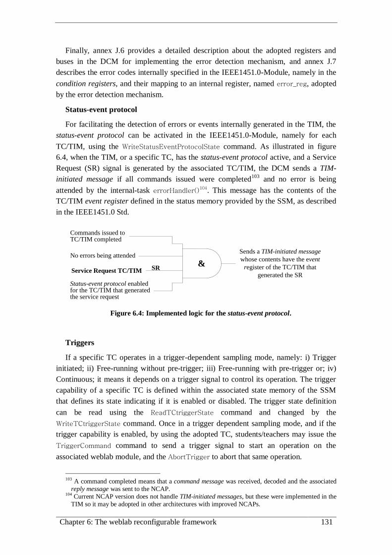
Chapter 6: The weblab reconfigurable framework 131
Finally, annex J.6 provides a detailed description about the adopted registers and
buses in the DCM for implementing the error detection mechanism, and annex J.7
describes the error codes internally specified in the IEEE1451.0-Module, namely in the
condition registers, and their mapping to an internal register, named error_reg, adopted
by the error detection mechanism.
Status-event protocol
For facilitating the detection of errors or events internally generated in the TIM, the
status-event protocol can be activated in the IEEE1451.0-Module, namely for each
TC/TIM, using the WriteStatusEventProtocolState command. As illustrated in figure
6.4, when the TIM, or a specific TC, has the status-event protocol active, and a Service
Request (SR) signal is generated by the associated TC/TIM, the DCM sends a TIM-
initiated message if all commands issued were completed103
and no error is being
attended by the internal-task errorHandler()104. This message has the contents of the
TC/TIM event register defined in the status memory provided by the SSM, as described
in the IEEE1451.0 Std.
Service Request TC/TIM
No errors being attended
Status-event protocol enabled for the TC/TIM that generated the service request
Sends a TIM-initiated message
whose contents have the event
register of the TC/TIM that
generated the SR
&
Commands issued to TC/TIM completed
SR
Figure 6.4: Implemented logic for the status-event protocol.
Triggers
If a specific TC operates in a trigger-dependent sampling mode, namely: i) Trigger
initiated; ii) Free-running without pre-trigger; iii) Free-running with pre-trigger or; iv)
Continuous; it means it depends on a trigger signal to control its operation. The trigger
capability of a specific TC is defined within the associated state memory of the SSM
that defines its state indicating if it is enabled or disabled. The trigger state definition
can be read using the ReadTCtriggerState command and changed by the
WriteTCtriggerState command. Once in a trigger dependent sampling mode, and if the
trigger capability is enabled, by using the adopted TC, students/teachers may issue the
TriggerCommand command to send a trigger signal to start an operation on the
associated weblab module, and the AbortTrigger to abort that same operation.
103 A command completed means that a command message was received, decoded and the associated
reply message was sent to the NCAP. 104 Current NCAP version does not handle TIM-initiated messages, but these were implemented in the
TIM so it may be adopted in other architectures with improved NCAPs.

132 An IEEE1451.0-compliant FPGA-based reconfigurable weblab
Events generated by the weblab modules
TCs running as event sensors use dedicated TC-event lines to inform the DCM that a
specific event occurred. A TC can only have one event line with no handshake protocol
required. A multiplexing mechanism is defined during the reconfiguration process
according to the number of TCs that may handle events. Internally, when a specific
event is detected by the DCM, it accesses an associated TC-task named event() for
performing the actions defined in its description (e.g. send a TIM-initiated message).
Figure 6.5 provides an illustrative diagram about the reconfigurable multiplexing
mechanism adopted for attending external events105
.
multiplexer
(reconfigurable)
event signal TC1event signal TC2
event signal TCn
...
Δ
event()
tasksevent()
tasks
Weblab module
event lines
TC-event lines
DCM event inputs
event busIEEE1451.0-Module
Δ - reconfigurable width
Figure 6.5: Adopted architecture to handle events generated by weblab modules.
6.2.2 TEDS-Module (TEDS-M)
TEDSs provide generic information about the whole infrastructure, i.e. the TIM, each
TC, and the associated weblab module. As part of its functionality, a TEDS contains
data fields with descriptive and control parameters for controlling the weblab modules’
operation. Current solution implements all TEDSs within the TEDS-M, which
integrates an internal controller that provides particular commands to write, read or
update each TEDS. The TEDSs’ contents are accessed by the DCM using command-
tasks and TC-tasks, through an hardware API. All TEDSs follow a particular structure
and are interfaced with an internal controller using a multiplexing mechanism.
Internally, the TEDS-M comprises a controller, a multiplexer and the TEDSs
memories, as illustrated in figure 6.6a). The DCM-TEDS-M access is made through a
set of commands according to a particular handshake protocol using a set of buses and
lines. As represented in figure 6.6b), each TEDS is divided in a memory comprising two
main blocks: i) a number of fields with the structure of TEDSs and; ii) 12 fields that
gather extra information about the TEDSs, namely current and maximum lengths,
status, etc. (similar to the reply of a QueryStatus command).
105 The TC-event lines are automatically connected to the multiplexer through an internal bus named
event_im. The bus width is specified in the configuration file defined during the reconfiguration
process and depends on the number of adopted TCs running as event-sensors, i.e. TCs with event
signals.
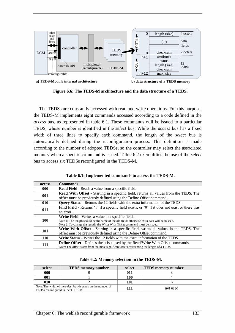
Chapter 6: The weblab reconfigurable framework 133
DCM
controller
multiplexer(reconfigurable)
TEDSTEDSTEDS
memoryaccess
select
reconfigurable
TEDS-MHardware API
b) data structure of a TEDS memorya) TEDS-Module internal architecture
length (size)
checksum
(...)
4 octets
data
fields
2 octets
0
n
n+1
n+12
attributesstatus
checksummax. size
12 octets
TE
DS
Info
. length (size)
other buses and lines
Figure 6.6: The TEDS-M architecture and the data structure of a TEDS.
The TEDSs are constantly accessed with read and write operations. For this purpose,
the TEDS-M implements eight commands accessed according to a code defined in the
access bus, as represented in table 6.1. These commands will be issued to a particular
TEDS, whose number is identified in the select bus. While the access bus has a fixed
width of three lines to specify each command, the length of the select bus is
automatically defined during the reconfiguration process. This definition is made
according to the number of adopted TEDSs, so the controller may select the associated
memory when a specific command is issued. Table 6.2 exemplifies the use of the select
bus to access six TEDSs reconfigured in the TEDS-M.
Table 6.1: Implemented commands to access the TEDS-M.
access Commands
000 Read Field - Reads a value from a specific field.
001 Read With Offset - Starting in a specific field, returns all values from the TEDS. The
offset must be previously defined using the Define Offset command.
010 Query Status - Returns the 12 fields with the extra information of the TEDS.
011 Find Field - Returns ‘1’ if a specific field exists, or ‘0’ if it does not exist or there was
an error.
100 Write Field - Writes a value to a specific field. Note 1: The length should be the same of the old field; otherwise extra data will be missed.
Note 2: To change the length, the Write With Offset command must be issued.
101 Write With Offset - Starting in a specific field, writes all values in the TEDS. The offset must be previously defined using the Define Offset command.
110 Write Status - Writes the 12 fields with the extra information of the TEDS.
111 Define Offset - Defines the offset used by the Read/Write With Offset commands. Note: The offset starts from the most significant octet representing the length of a TEDS.
Table 6.2: Memory selection in the TEDS-M.
select TEDS memory number select TEDS memory number
000 0 011 3
001 1 100 4
010 2 101 5 Note: The width of the select bus depends on the number of
TEDSs reconfigured in the TEDS-M. 111 not used

134 An IEEE1451.0-compliant FPGA-based reconfigurable weblab
The TEDS-M responds to: i) DCM internal-tasks, used when the IEEE1451.0-
Module receives commands and; ii) TC-tasks, belonging to a particular implementation
of a weblab module, which are automatically embedded into the DCM during
reconfiguration. Therefore, since the main objective is to provide a reconfigurable
infrastructure able to control different weblab modules agnostic to implementation
details of the TEDS-M, an abstraction layer implemented by an hardware API was
created to simplify the access to the TEDSs’ contents. As illustrated in figure 6.7, the
API accesses the commands of the TEDS-M using an handshake protocol. It is
implemented by different tasks within the Access_ModTEDS.vh file, providing the
instructions described in table 6.3, which have a set of I/O parameters to interact with
DCM internal registers.
...Hardware
API
(Access_ModTEDS.vh)
taskstasks
tasks
Controller (commands)
Memories(TEDSs)
DCM
weblab module
The DCM-TEDS-M interface is
established according to a particular
handshake protocol that uses a set of
bus lines.
Instructions provided in the hardware
API manage all signals on the bus
lines to access the TEDSs memories.
TEDS-M
Bu
s li
nes
Figure 6.7: Layered structure supported by the Access_ModTEDS hardware API to
access the TEDSs memories reconfigured in the TEDS-M.
Table 6.3: Instructions provided by the Access_ModTEDS hardware API.
ModTEDS_ReadField
Reads all fields associated to a TLV structure defined in a TEDS memory.
ModTEDS_WriteField
Writes all fields associated to a TLV structure defined in a TEDS memory.
ModTEDS_ReadWithOffset
Reads all fields of a TEDS memory after a selected offset.
ModTEDS_WriteWithOffset
Writes all fields of a TEDS memory after a selected offset.
ModTEDS_QueryStatus
Returns the status register of a TEDS memory.
ModTEDS_WriteStatus
Writes the status register of a TEDS memory.
ModTEDS_FindField
Finds a field in a TEDS memory.
Annex J.8 presents details about the TEDS-M, namely the definition of internal
variables, the internal schematics, the handshake protocol adopted for interfacing the
DCM, and details about the instructions provided by the hardware API.

Chapter 6: The weblab reconfigurable framework 135
6.2.3 Status/State Module (SSM)
This module provides access to two independent memories, whose contents specify
the status and operating states of the TCs/TIM. During DCM operations those memories
will be accessed by different tasks to update their status and states. The access to those
memories is made through a set of commands provided by an internal controller, whose
access can be made by another hardware API.
Internally, the SSM comprises a controller, a multiplexer and the status and the state
memories, as illustrated in figure 6.8a). The length of these memories depends on the
number of adopted TCs, and their structures are divided into several segments, as figure
6.8b) represents. The status memory has segments with 3 registers of 32 bits wide, each
associated to a particular TC/TIM, namely the condition, event and mask registers.
These are changed according to the status message generation logic defined by the
IEEE1451.0 Std., implemented by the internal status/state controller. The state memory
has segments with 2 registers of 8 bits wide, each also associated to a particular
TC/TIM. The segments gather the: i) operating states of each TC/TIM, namely if they
are in the initialization, active, sleep, operation or idle states and; ii) the trigger state,
that indicates if a specific TC has its trigger enabled or disabled (the TIM does not have
trigger states). The length of both memories is defined through internal parameters
changed during the reconfiguration process.
DCM
controller
multiplexer(reconfigurable)
status
memory
state
memory
access
address
reconfigurable
SSMHardware API
b) status/state memory structuresa) SSM internal architecture
conditioneventmask
conditioneventmask
conditioneventmask
....
TIM
TC1
TC2
(TCn+1)*3
statenot used
statetriggerstate
triggerstate
trigger....
TIM
TC1
TC2
(TCn+1)*2statu
s m
emory
(32 b
its)
state
mem
ory
(8 b
its)
TC3
other buses and lines
Figure 6.8: The SSM architecture and the status/state memories structures.
To simplify the access to both the status and the state memories, the SSM provides a
set of four commands decoded by its internal controller, as indicated in table 6.4.
Issuing a command to this module does not require selecting the memory to access,
since it is the command itself that handles this issue, indicated by the access bus. The
memory addresses must be defined by the address bus, whose width is automatically
defined during reconfiguration, according to the number of implemented TCs. When the
controller detects one command, it is decoded to trigger a specific procedure according
to the accessed memory and the executed operation (read or write).

136 An IEEE1451.0-compliant FPGA-based reconfigurable weblab
Table 6.4: Implemented commands to access the SSM.
access Commands
00 writesStatus - Writes into a status register.
The type of register is automatically detected (condition, event or mask).
01 readsStatus - Reads a status register. The type of register is automatically detected (condition, event or mask).
10 writesState - Writes into a state register.
The type of register is automatically detected (state or trigger).
11 readsState - Reads a state register.
The type of register is automatically detected (state or trigger).
Reading the state memory using the readState command does not require any
specific procedure within the controller. Forcing a transaction between states, i.e.
issuing the writesState command to change the operating state of a specific TC/TIM,
requires evaluating if that transaction is valid. This is internally made by consulting an
internal Look Up Table (LUT) that contains all valid transactions. Since the current
version does not distinguish the trigger states of any TC/TIM, changing a trigger state
only sets or resets bit 0 of each register, and no further processing is made, except when
trying to change the TIM trigger state. In this situation, an error will be generated, since
the TIM does not have any associated trigger.
The complexity increases when using the writesStatus and the readsStatus
commands. When these commands are issued, the SSM automatically detects what type
of register will be accessed (condition, event or mask). By issuing a writesStatus to a
condition or mask registers, the controller activates the status message generation logic
defined by the IEEE1451.0 Std. Since there is no IEEE1451.0 command able to change
the event register, the SSM does not enable writing event registers, generating an error
if there is a request to do such operation. By issuing the readsStatus, the controller reads
a register of any type and, if it is an event register, it will also clear its contents.
As represented in figure 6.9a), all bits of the TIM condition register represent an OR
logic of all bits in each TC condition register. In other words, when a bit is set in a TC,
the correspondent bit in the TIM will be also set. In situations where an error is caused
only by the TIM, i.e. not associated to a particular TC, only the bits in the TIM are set.
The same OR logic is applied when a SR is generated according to the status message
generation logic, as represented in the same figure 6.9b). Every SR generated by TCs or
by the TIM, sets a specific bit in an internal register named servReq, whose length
depends on the adopted TC defined during reconfiguration. Since an OR logic is
adopted for generating a SR to the whole infrastructure, every SR generated by a
specific TC or by the TIM, triggers a generic signal, which may originate a TIM-
initiated message if the status-event protocol is active for that TC/TIM, as previously
described.

Chapter 6: The weblab reconfigurable framework 137
TIM bit_n
SR
TC1
SR
TIM
SR
TC2
SR
TCn (...)
servReq internal register
Service_Request
(SR)
bit_n
TC2
bit_n
TC1
bit_n
TC3
bit_n
TC n (...)
Status bits of each TC/TIM condition register
Bits in the TIM condition register are asserted based on an OR logic.
The SR signal remains set if a SR of any TC/TIM is also set. The servReg gathers all values of the SRs associated to each TC/TIM.
The bits of the servReg are cleared after:i) reading an event register;ii) sending a TIM-initiated message caused by a SR when the status-event protocol is active; iii) clearing the event register.
OROR
a) TIM bits logic of the condition register b) Service request generation logic
Figure 6.9: Implemented logic for the condition registers and for the SR signal.
Both the status and state memories are accessed by: i) DCM internal-tasks, used
when this last module receives commands and; ii) TC-tasks belonging to particular
implementation of a weblab module, which will be automatically embedded into the
DCM during the reconfiguration process. With a schema similar to the one adopted for
the TEDS-M, an hardware API facilitates the access to those status and state memories
using the commands of the SSM, as illustrated in figure 6.10. This API is implemented
by different tasks within the Access_ModStatusState.vh file, providing the instructions
described in table 6.5, which have a set of I/O parameters to interact with DCM internal
registers.
...Hardware
API
(Access_ModStatusState.vh)
taskstasks
tasks
Controller (commands)
Memories(state/status)
DCM
weblab module
The DCM-SSM interface is established
according to a particular handshake
protocol that uses a set of bus lines.
Instructions provided in the hardware
API manage all signals on the bus
lines to access the status and the state
memories.
SSM
Bu
s li
nes
Figure 6.10: Layered structure supported by the Access_ModStatusState hardware API
to access the SSM status and the state memories.
Table 6.5: Instructions provided by the Access_ModStatusState hardware API.
ModStateStatus_Read
Reads the status or the states of a particular TC or TIM.
ModState_Write
Defines the state for both TCs and TIM, and defines if the trigger is active for a particular TC.
ModStatus_Write
Changes the condition, event or mask registers of a particular TC or TIM.

138 An IEEE1451.0-compliant FPGA-based reconfigurable weblab
Annex J.9 presents several details about the SSM, namely the definition of internal
variables, the schematics with the adopted buses and lines, the handshake protocol
adopted for interfacing the DCM, and the instructions provided by the hardware API.
6.2.4 UART Module (UART-M)
The UART-M establishes the interface between the IEEE1451.0-Module and the
NCAP using the control/monitor connection implemented by an RS-232 interface. It is
controlled by the DCM using an handshake protocol that manages a set of signals to
access two internal buffers and to control all data-flow during transmissions. The
UART-M also implements a mechanism for validating and creating command, reply
and TIM-initiated messages structures defined by the IEEE1451.0 Std.
As represented in figure 6.11, the UART-M comprises three independent modules:
the Tx, Rx and the BR_generator. The Tx and Rx modules manage all data
transmissions, and the BR_Generator module defines the data rate according to a clk
signal that is also used to synchronize all the other modules within the IEEE1451.0-
Module. Data transmissions are made through the tx and the rx lines.
Rx bufferrx
data handshakelines
verify command messages structures
Tx buffertx
create reply and TIM-initiated messages structures
DCM
data TEDS-M
clkBR_Generator
[defines the baud rate for RS-232 transmissions and for the operation of other modules]
clk_out clk_out
SSM
weblab
moduleclk_out
tx
UART-M
Rx Tx
error
Figure 6.11: The architecture of the UART-M and the interface with the remaining
modules of the IEEE1451.0-Module.
Besides providing the interface to the whole TIM, it also implements specific
features in the Tx and Rx modules. The Rx module has an internal mechanism that
evaluates if the received command message structures are in accordance with the
IEEE1451.0 Std. It verifies if the format and length of the received structures are valid,
and if the synchronization bits follow the implemented solution that uses one start bit
and two stop bits without parity check. If valid, the Rx module fills-in its internal
buffer. Otherwise, if an inconsistency is detected, i.e. the length does not correspond to
the remaining data sent in a specific structure, or if it does not have the delimiters start
and stop bits, the UART-M generates an error, sending it to the DCM by turning high
the logic signal of the error line. The Tx module gathers all data sent by the DCM in its

Chapter 6: The weblab reconfigurable framework 139
internal buffer, so it may transmit TIM-initiated messages or command reply messages.
The baud rate is controlled by the BR_generator module that receives a clock signal in
the clk line and generates a new clock with a lower frequency through the clk_out line.
This line is used for synchronizing all modules of the IEEE1451.0-Module and some
weblab modules, except the ones that run at different frequencies, which may use other
clock signals generated by other modules designed by weblab modules’ developers.
Annex J.10 illustrates the UART-M schematics, and the buses, lines and handshake
protocols used by the Rx and Tx modules to receive/transmit data from/to the NCAP.
6.3. The weblab connecting modules: layout and interface
To bind weblab modules to the IEEE1451.0-Module, developers should follow a
specific process and define all parts, which include one or more modules connected
through TCs using a set of TC-tasks described in Verilog HDL and embedded in the
DCM [143][144]. As previously referred, these TC-tasks establish the interface between
the IEEE1451.0-Module and each weblab module, enabling their control according to
TEDSs, also defined by the developer. The number of TCs depends on the architecture
and parameters to control on each weblab module. In the next subsections all parts
required to define the weblab modules are detailed, namely their architecture, the
number of TCs and their operating modes, the TC-tasks embedded in the DCM and, the
methodology for developing those modules.
6.3.1 Internal architecture
A weblab module compatible with the IEEE1451.0-Module comprises an
architecture divided in 3 distinct parts: i) HDL files describing the module itself; ii) TC-
tasks to control and interface the module with the DCM and; iii) TEDSs to define the
behaviour of the entire IEEE1451.0-Module and of each TC adopted to interface the
weblab module and the DCM. As illustrated by figure 6.12, each weblab module is
accessed by one or more TCs controlled by TC-tasks managed according to the data
available within the TEDS and status/state memories.
Weblab module design
TC lines
IEEE1451.0-Module
weblab module
TEDS-M DCM
HDL module
SSM
Status StateMemory
Buffer (MB)
TC lines
taskTC-task
......
Represents the TC-tasks accessing the
modules / MB
Target
experiment
UART-M
TC-taskTC-task
TC-taskTC-task
HDL moduleHDL module
I/O
TEDSTEDSTEDS
Figure 6.12: Parts required for defining a weblab module compatible with the
IEEE1451.0-Module.

140 An IEEE1451.0-compliant FPGA-based reconfigurable weblab
The TC-tasks are responsible for accessing the TEDS-M, the SSM, the UART, and
the MB, which gathers temporary data used by some IEEE1451.0 commands and by the
weblab module itself during read/write operations in their DSs. To simplify the design,
each TC-task accesses the weblab modules using the hardware APIs referred in previous
subsections 6.2.2 and 6.2.3, facilitating this way their description and independence
towards the specificities of the DCM implementation.
There are required and optional TC-tasks that should be defined according to the
adopted TC, so the DCM may automatically use them to handle received commands
from the NCAP or events generated by the weblab modules. The number of adopted
TCs depends on developers’ options and should take into consideration the parameters
to control in a particular weblab module, the TEDSs’ definitions, and the resources
available in the FPGA.
6.3.2 Required Transducer Channels
In a traditional weblab module, several commands are required to start a
measurement or to read/write a specific signal from/into an external device connected to
a target experiment. For example, to generate a waveform signal using a Function
Generator (a type of a weblab module), developers should define, at least, three
parameters: the waveform type, the amplitude and the frequency. These or other
parameters should also be controlled in similar weblab modules connected to the
IEEE1451.0-Module. The control of the weblab modules is managed by TCs, whose
behaviour is defined according to TEDSs, in particular by the contents of the associated
TC-TEDSs able to be changed using IEEE1451.0 commands (e.g. WriteTEDSsegment).
Depending on the defined sampling mode, different commands may be issued to a
particular TC. Per example, if specific data is required to read/write from/to a weblab
module, the associated TC should provide access to its internal DSs, whose contents
will be transferred to/from the MB, according to the data flow illustrated in figure 6.13.
Memory
Buffer
(MB)
TC-tasksDS
DSDS
TClines
IEEE1451.0-Module
11
1
2
22
Weblab module design
Target
experimentNCAP
Embedded weblab module
(write)
(read)
(read)
(write)
Figure 6.13: Data flow between the DCM and the weblab modules.
Dashed lines 1 represent data writing operations and dashed lines 2 data reading
operations. Using the MB to gather all data during both operations is fundamental in
order to guarantee an abstraction layer between the IEEE1451.0-Module, in particular

Chapter 6: The weblab reconfigurable framework 141
the DCM, and the TC-tasks described for each weblab module. This way, during their
description, developers only need to know how to access the MB and the external DCM
modules (TEDS-M and SSM), which is simplified using the interfaces provided by the
hardware APIs described in subsections 6.2.2 and 6.2.3.
As illustrated in figure 6.14, there are two solutions for controlling the parameters of
the weblab modules: i) using several TCs for individually controlling each parameter or;
ii) using one TC controlling more than one parameter through encoding/decoding
processes.
TC 1
TC-TEDS
User’s Transducer Name TEDS
Meta TEDS
IEE
E1
45
1.0
-Mo
du
le
MD-TEDS
TC
lines
a) One TC for individually controlling one parameter
parameterto control
I/O
Memory
Buffer
(MB)
DS
tasks
DS
TC 2
TC-TEDS
MD-TEDS
TC
lines
DS
tasks
DS
TC n
TC-TEDS
MD-TEDS
TC
lines
DS
tasks
DS
....
TC
linesI/O
DSDSTC
TC-TEDS
MD-TEDS
TC encoder/decoder
TC
encoder/
decoder
DS
tasks
Memory
Buffer
(MB)
Em
bed
ded
web
lab
mo
du
le
User’s Transducer Name TEDS
Meta TEDS
parametersto control
b) One TC may control several parameters
Em
bed
ded
web
lab
mo
du
le
IEE
E1
45
1.0
-Mo
du
le
Figure 6.14: Possibilities for controlling weblab modules parameters using TCs.
In the first solution (figure 6.14a), users control individually each weblab module
through several TCs. This means that a weblab module requiring the control of several
parameters also requires several TCs and associated TC-tasks, several buses attached to
the IEEE1451.0-Module and, at least, one TC-TEDS for each TC. Despite the
possibility of a well defined control over the parameters of a weblab module, this
solution is more resource-consuming, which may become impracticable when using a
single FPGA to accommodate the IEEE1451.0-Module and all the weblab modules.
The second solution (figure 6.14b), is less resource-consuming (less TEDSs and a
single bus attached to the weblab module), but it requires extra-processing units to
encode/decode the data transferred using the TC, both in the TC-tasks and in the
modules indicated in the figure as the Embedded weblab module. By
encoding/decoding the data transferred through the TC, the IEEE1451.0-Module can
define the required parameters to control the weblab module.
The flexibility provided by both solutions may be applied to situations that use a
chain of several weblab modules connected through a daisy chain bus, as represented in
figure 6.15. In this situation, developers should define the handshake protocol between

142 An IEEE1451.0-compliant FPGA-based reconfigurable weblab
each TC-task and the TC encoder/decoder that should also provide a multipoint protocol
to access each parameter. An example of a multipoint protocol that can be adopted is the
Wishbone Bus106
, which is an open source hardware computer bus typically used to
interface different modules within an FPGA. The entire protocol can be implemented by
the TC encoder/decoder (defined outside of the TC-tasks) to manage the daisy chain
bus, providing an access to each weblab module and, in particular, to its parameters.
User’s Transducer Name TEDS
Meta TEDS
TC
lines
represents parameters able to control in a weblab module
I/O
Memory
Buffer
(MB)
TC
TC-TEDS
MD-TEDS
TC enc/dec
EncoderDecoder
TC-tasks
Embedded weblab modules
TC encoder/decoderimplements a multipoint protocol responsible for redirecting all
DCM accesses to/from a particular parameter
DS
...
TC
TC-TEDS
MD-TEDS
TC enc/dec
TC-tasks
I/O
DS
I/O
DS
( ... )
Des
ign
ed d
ais
y c
ha
in b
us
EncoderDecoder
EncoderDecoder
IEE
E1
45
1.0
-Mo
du
le
Figure 6.15: Control of a daisy chain bus with the modules connected to the
IEEE1451.0-Module.
Developers may adopt one or both solutions that require TEDSs to characterize the
behaviour of a weblab module. This is the case for TCs, which must be associated with
a single TC-TEDS that may not provide all fields required to characterize their
behaviour. When this situation occurs, developers may define extra fields in the TC-
TEDS, or they may adopt other TEDSs, such as MD-TEDSs. Both options are in
accordance with the IEEE1451.0 Std., and satisfy the requirements posed by every
weblab module, since they allow users to monitor or define the behaviour of the TCs
through specific TEDSs’ fields. Then, developers should evaluate their options upon the
control level required for each weblab module, and the coherence of the TC-TEDS and
other associated fields of the adopted TEDSs, with the characteristics of the I/O signals
(e.g. associated units, ranges, etc.). In other words, a solution based on a single TC able
to control several parameters of a specific weblab module should be only adopted if the
TEDSs’ contents describe all relevant features of the associated I/O.
Whatever the adopted solution, its implementation should be made either in each
weblab module or in the daisy chain bus structure, and in the IEEE1451.0-Module by
defining a set of TC-tasks for each adopted TC. These TC-tasks are embedded into the
DCM through an automatic reconfiguration, and may implement any type of handshake
protocol to interface the weblab modules.
106 The Wishbone Bus is SoC architecture describing a flexible design methodology for interfacing
portable IP cores (http://opencores.org/opencores,wishbone).

Chapter 6: The weblab reconfigurable framework 143
6.3.3 TC-tasks
Depending on the operation mode defined for a particular TC and the applied
command, a specific procedure should be used to access the TEDSs, configure the
parameters of a weblab module, and to transfer data between the MB and the DSs
available within each weblab module. The TCs lines and the associated handshake
protocol, used to access a weblab module, are defined by the developers. There are no
restrictions, since the definition of a weblab module includes the definition of the
associated HDL modules and the TC-tasks to be embedded into the DCM, as illustrated
in the previous figure 6.12. This means that developers may define their own protocol
or select a specific one, like the Wishbone Bus. The only requirement posed to
developers is to follow a set of operational rules defined for the TC-tasks, since most of
these tasks are accessed when a specific command is received by the DCM.
There are mandatory and optional TC-tasks that, according to the association
illustrated in figure 6.16, are embedded into the DCM and accessed when a specific
command, numbered by its class and function, is issued, or when an event is generated
by a TC running as an event sensor. The DCM automatically decodes received
commands and accesses associated TC-task. It automatically accesses the event() TC-
task when is the weblab module that generates an event. The internal tasks descriptions
include instructions to access the TEDS-M and the SSM to read, write or update their
internal memories according to the operation of a weblab module, and the UART-M to
enable the data transmission to/from the NCAP. TC-tasks have their specific functions,
since most of them are associated to a particular command. The exception is the init()
that is always accessed during power-up, and the event() that is not associated to any
particular command. This last particular TC-task is accessed when an event is
generated, and it may interact with all the other modules connected with the DCM.
stop()
start()
rd()
wr()
TC-tasks
3.2-WriteTCDSsegment
3.1- ReadTCDSsegment
3.4- AbortTrigger
3.3- TriggerCommandWeblabmodule
Weblab module design
1.4- updateTEDS
7.1-Resetinit()
update()Bus lines
parameters to control
bufferDS
- Commands are numbered according to classes and functions defined in the IEEE1451.0 Std.- Depending on the sampling mode, commands may use one or more tasks.
processing
modules
processing
module
DCM
event()May access different features in the DCM
(TEDS and status/state memories, MB, or
transmit a TIM-initiated message)event
Figure 6.16: Association between IEEE1451.0 commands and TC-tasks.

144 An IEEE1451.0-compliant FPGA-based reconfigurable weblab
Thus, seven TC-tasks (some optional), may be specified for each TC, according to
the adopted sampling mode defined in the TC-TEDS, and each one should implement
specific features, namely:
start() and stop() - [optional] - Used by TCs that adopt sampling modes with
triggers. These tasks start/stop the operation of the weblab modules indicating
they can begin/end acquiring or sampling data to/from their internal DSs.
Accessed by the commands AbortTrigger (3.4) and TriggerCommand (3.3);
rd() - [optional] - Performs a read operation. DSs are copied into the MB so they
may be automatically accessed by the DCM. Accessed by the command
ReadTCDSsegment (3.1);
wr() - [optional] - Applied to TCs running as actuators. It performs a write
operation by copying the contents of the MB into the DSs. These contents can be
immediately outputted if the TC runs in an immediate mode, otherwise it can
only output data on the reception of a trigger command using the start() TC-task.
Accessed by the command WriteTCDSsegment (3.2);
init() - [required] - Initializes TCs by accessing the contents of the associated
TEDSs and defining their current operation (e.g. sampling time). The TCs go to
an idle state. Accessed by the command Reset (7.1) and during a power-up;
update() - [required] - Updates the operation of TCs based on the contents of
TEDSs. Accessed by commands Read/WriteTCDSsegment (3.1/3.2),
TriggerCommand (3.3) and updateTEDS (1.4);
event() - [optional] - Only used by TCs running as event sensors, which generate
event signals. This task may access different features of the IEEE1451.0-
Module, such as TEDSs and status/state memories, the MB, or simple transmit a
TIM-initiated message to the NCAP. It is not associated to any command.
Annex K.1 exemplifies the HDL code required for all TC-tasks specified by the
developers of each weblab module.
The init() TC-task is accessed after a power-up or after the reception of a reset
command. It should initialize the weblab modules associated to a particular TC, which
typically includes an access to the TEDS-M and SSM memories. The other TC-tasks
impose some other operational sequences when accessed, as illustrated in figure 6.17.
For TCs operating in trigger-dependent modes, issuing the TriggerCommand and the
AbortTrigger commands, enables the DCM to access the update() TC-task, as
represented in figure 6.17a). This should configure the parameters of a weblab module
associated to the TC, by accessing the TEDS-M and the SSM. Latter, the DCM may
access the start() TC-task to start a specific operation in the weblab module associated
to that TC, such as I/O data to/from its internal DSs. The reception of the AbortTrigger
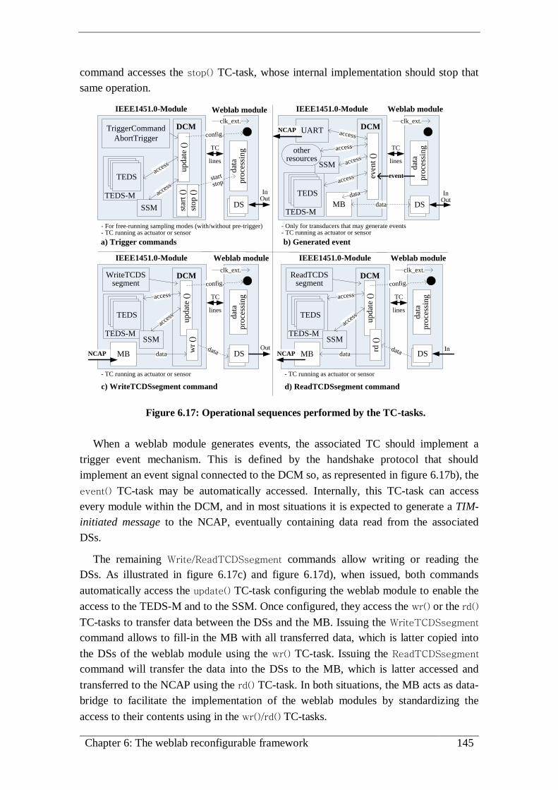
Chapter 6: The weblab reconfigurable framework 145
command accesses the stop() TC-task, whose internal implementation should stop that
same operation.
DS
TriggerCommand
AbortTrigger
DS
dat
a pro
cess
ing
TEDSTEDS access
clk_ext.
TEDS
- For free-running sampling modes (with/without pre-trigger)- TC running as actuator or sensor
IEEE1451.0-Module
updat
e ()
star
t ()
stop (
)
DCM
TC
lines
config.
start
stop
TEDS-M
SSM
Weblab module
a) Trigger commands b) Generated event
c) WriteTCDSsegment command d) ReadTCDSsegment command
InOut
DSDS
dat
a pro
cess
ing
TEDSTEDS
access
clk_ext.
TEDS
IEEE1451.0-Module
even
t ()
DCM
TC
lines
TEDS-M
SSM access
Weblab module
UART access
other resources
MB
access
data
data
InOut
acce
ss
NCAP
event
- Only for transducers that may generate events- TC running as actuator or sensor
DSDS
dat
a pro
cess
ing
TEDSTEDS
clk_ext.
TEDS
IEEE1451.0-Module
DCM
TC
lines
TEDS-MSSM
Weblab module
WriteTCDSsegment
MB
access
datadata
Out
updat
e ()
wr
()
acce
ss
NCAP
config.
DSDS
dat
a pro
cess
ing
TEDSTEDS
clk_ext.
TEDS
IEEE1451.0-Module
DCM
TC
lines
TEDS-MSSM
Weblab module
ReadTCDSsegment
MB
access
datadata In
updat
e ()
rd (
)
acce
ss
NCAP
config.
- TC running as actuator or sensor - TC running as actuator or sensor
Figure 6.17: Operational sequences performed by the TC-tasks.
When a weblab module generates events, the associated TC should implement a
trigger event mechanism. This is defined by the handshake protocol that should
implement an event signal connected to the DCM so, as represented in figure 6.17b), the
event() TC-task may be automatically accessed. Internally, this TC-task can access
every module within the DCM, and in most situations it is expected to generate a TIM-
initiated message to the NCAP, eventually containing data read from the associated
DSs.
The remaining Write/ReadTCDSsegment commands allow writing or reading the
DSs. As illustrated in figure 6.17c) and figure 6.17d), when issued, both commands
automatically access the update() TC-task configuring the weblab module to enable the
access to the TEDS-M and to the SSM. Once configured, they access the wr() or the rd()
TC-tasks to transfer data between the DSs and the MB. Issuing the WriteTCDSsegment
command allows to fill-in the MB with all transferred data, which is latter copied into
the DSs of the weblab module using the wr() TC-task. Issuing the ReadTCDSsegment
command will transfer the data into the DSs to the MB, which is latter accessed and
transferred to the NCAP using the rd() TC-task. In both situations, the MB acts as data-
bridge to facilitate the implementation of the weblab modules by standardizing the
access to their contents using in the wr()/rd() TC-tasks.

146 An IEEE1451.0-compliant FPGA-based reconfigurable weblab
6.3.4 Development methodology
Following the presented guidelines, the development of weblab modules compatible
with the IEEE1451.0-Module must follow the sequence presented in the diagram of
figure 6.18.
Evaluate
requirements and
features for the
weblab module
Select the required I/Os
of the weblab module to
interface the target
experiment
Select the
weblab module
control
parameters
Select the number and type
of TCs required to access
the weblab module control
parameters
Select and describe the
TC-tasks
Define the TEDSs for the
TIM and for the selected
TCs
Bind the weblab module to
the IEEE1451.0-Module
using the RecTool
Figure 6.18: Methodology for designing weblab modules compatible with the
IEEE1451.0-Module.
Developers should start by evaluating the requirements and features of the weblab
module they want to design. It is fundamental to evaluate its complexity to understand
what modules should be defined in the FPGA. For this purpose, the I/Os should be
selected, namely the associated signals, and if they act as actuators, sensors or event
sensors. In the current architecture, those I/Os are managed by one or more parameters
that should be controlled using one or more TCs. Therefore, after selecting the I/Os and
the parameters to control, developers should define the number of TCs. That definition
should be made according to the type of parameters they want to control and the
requirements posed to the FPGA, since the use of several TCs may require many
associated TEDSs, which may require many FPGA resources. Once the number of TCs
is selected, developers should define the TEDSs to describe the TIM architecture and
the weblab module behaviour. Current solution suggests that at least the TC-TEDS
should be defined for each selected TC. Nevertheless, developers may define other
TEDSs described by the IEEE1451.0 Std., like a MD-TEDS that allows defining extra
fields to specify the behaviour of a particular TC, and therefore, of the weblab module.
The way TCs are controlled is made by the TC-tasks selected according to the
adopted sampling mode using any type of signals connected to the weblab modules. So,
it is up to developer to decide which will be the TC-tasks used to control each TC and
the way they are implemented, so they can provide the interface to the other modules
within the IEEE1451.0-Module. In order to simplify the developments, during the
description of each TC-task, developers may use the hardware APIs provided to access
the TEDS-M and the SSM and, for the event() TC-task, the protocol adopted in the TC
to control the data transmission/reception of the UART-M. After all these definitions, a
specific weblab module is available to connect to the IEEE1451.0-Module using the
reconfiguration process supported by the RecTool.
Therefore, developing the weblab modules requires defining their TEDSs and their
internal layouts and interfaces. To avoid going into many details in this chapter, it was

Chapter 6: The weblab reconfigurable framework 147
decided to provide some annexes with an example of a TEDS and a MT design,107
and
with examples of compatible weblab modules, some of them adopted in the validation
& verification process described in the next chapter 7.
Annex K.2 exemplifies the design of TEDSs (and MTs).
Annex K.3 presents some weblab modules, namely: i) two digital I/O modules
(annex K.3.1); ii) one step-motor controller module (annex K.3.2) and; iii) a simple
event sensor (annex K.3.3) designed just to validate the operation of the IEEE1451.0-
Module with TCs running as event-sensors.
6.4. The reconfiguration process
To reconfigure the weblab infrastructure, namely the TIM, it is necessary to select
weblab modules and specify the way they are connected to the IEEE1451.0-Module.
Students, teachers or technicians must specify a set of rules in a configuration file, and
select other project files describing the weblab modules and other internal connections.
They must follow a specific methodology supported by the RecTool already presented
in the previous chapter, whose panels and files are illustrated in figure 6.19.
Weblab
modules
(*.teds, *.v,
*.vh) - Files
describing the
weblab modules.
MT file (*.map) -
Mapping file required to
associate the TEDSs’
memories to the TCs and
to the TIM.
UCF file (*.ucf) - Specifies
the I/O pinout of the FPGA-
based board used by the
weblab modules.
Weblab
projects
(*.bit or
*.svf) -
Binary files
of the
generated
weblab
projects.
Reports
(*.rep) -
Reports
generated
during the
reconf.
process.
2013-04-17_14:34:12.svf
Upload section
- Enables
uploading files
to the weblab
server.Information section - Presents all information
during users’ interaction with the RecTool.
Panels section - Has all files required for reconfiguring the weblab
infrastructure. It is divided in three other panels: i) build panel, has the
files required to created the weblab project; ii) reconfiguration panel,
has all synthesized files for reconfiguring the infrastructure and; iii)
reports panel, provides the reports generated during the reconfiguration.
Configuration
files (*.conf) -
Contain the rules
for redefining
the weblab
project (e.g.
generate and
interface project
files, specify the
configurations
for interfacing
the weblab
modules, etc.).
Figure 6.19: The RecTool interface panels and files used for reconfiguring the weblab
infrastructure.
107 MTs are used in the reconfiguration process and they are designed in the same way as TEDSs.

148 An IEEE1451.0-compliant FPGA-based reconfigurable weblab
This tool generates the weblab project bitstream file that includes the selected weblab
modules, and reconfigures the TIM according to a particular reconfiguration sequence.
6.4.1 The reconfiguration sequence
The RecTool was developed to allow users (students/teachers/technicians) keep
tracking of all operations made during the reconfiguration process. The most common
sequence involves three main operations: i) build the weblab project binding the weblab
modules to the IEEE1451.0-Module; ii) synthesize the project to create a *.bit or a *.svf
file and; iii) sending that file to the weblab infrastructure, namely to the NCAP that will
reconfigure the TIM. During this sequence, users interact with the RecTool interface
from different access stages, according to the sequence illustrated in figure 6.20.
The access stage depends on users requirements, i.e. if they want to create a new
weblab project or to use an already synthesized one, available in the RecTool. Five
access stages are considered:
Access stage 1 - After uploading the project/configuration files, users either
follow the entire sequence or go to access stages 4 or 5 to reconfigure the TIM;
Access stage 2 - Users have already all project files in the RecTool to create a
new weblab project. No uploading is required, but they should follow the
remaining sequence;
Access stage 3 - The weblab project is already built and available to be
synthesized;
Access stage 4 - The binary files (*.bit) for reconfiguring the FPGA are already
available in the RecTool. Users should select one *.bit file that will be converted
to an *.svf file to reconfigure the TIM;
Access stage 5 - An *.svf file is available to reconfigure the TIM. This access
stage is the simplest one because the weblab server only needs to send the file
and monitor the reconfiguration process. No file conversion (*.bit to *.svf) is
required, only a report will be generated.
During upload, only relevant file types are allowed (*.conf/ucf/vh/v/teds/map). Once
selected and uploaded, they will be placed in the users’ Weblab Server File System
(WSFS) space appearing in the RecTool interface panel (e.g. if users select a
configuration file, it will be automatically placed in the build configuration panel).
Next, users should select the files to build the weblab project. In this operation, the
RecTool activates a validation mechanism to guarantee that only allowed files are
selected with the correct cardinality (e.g. only one *.map and *.ucf files can be
selected).

Chapter 6: The weblab reconfigurable framework 149
Fig
ure
6.2
0:
Th
e co
mp
lete
rec
on
figu
rati
on
seq
uen
ce u
sin
g t
he
Rec
To
ol.

150 An IEEE1451.0-compliant FPGA-based reconfigurable weblab
At the end, users should initiate the build operation, which is concluded almost
instantaneously because the processing power required from the weblab server machine
is reduced, and therefore, the time consumed is short (a few seconds), which does not
happen during the synthesis operation. If there are no reported errors after the build
operation, users should start the synthesis. This may be much time consuming, from a
few minutes to hours, depending on the complexity of the weblab project that is related
with the selected weblab modules, the weblab server processing power, and the reported
errors, i.e. if during the synthesis operation an early error is detected, it stops the
synthesis in a short period of time, otherwise it may take hours before stopping and
retrieving that error. Although users may stop the synthesis by pressing the StopSyn
button, it was decided to run the synthesis operation in background, so they can keep
interacting with the RecTool, but with some restrictions, namely: i) they cannot start
another synthesis, since the involved consuming processing power may stuck the
weblab server machine or increase much more the time required to finish the operation
and; ii) the build operation becomes inactive, because users cannot change the weblab
project files while a synthesis operation is running. Nevertheless, users can still access
the RecTool at access stages 4 and 5, i.e. they can reconfigure the weblab infrastructure
with solutions already available in their WSFS space. To alert users that a synthesis
operation has finished, the RecTool automatically sends an e-mail indicating users
should consult the RecTool interface, namely the Syn report to evaluate if the synthesis
was successful. If there are no reported errors, a *.bit file becomes available so users
may select it to start the reconfiguration operation.
The reconfiguration operation is not so time consuming as a synthesis operation. It
involves sending an *.svf file to the weblab infrastructure through the NCAP. Users start
the reconfiguration process by selecting a *.bit or *.svf files in accesses stages 4 or 5. In
access stage 4, the selection of a *.bit file requires using the RecTool to create the *.svf
file that will be automatically transferred to the NCAP, becoming available in the
reconfiguration panel for future reconfigurations. In access stage 5, the *.svf file is
already available to be transferred, and no file conversion is required. Both accesses
require some processing in the RecTool but, since they are concluded in a few seconds,
they do not run in background. The generated reports give possible errors occurred
during the reconfiguration (Reconf_date.rep) and during the creation of the *.svf file
(svf_date.rep). When errors occur, information will be displayed in the information
panel and in the generated reports. In the situation of an unsuccessful reconfiguration
not detailed in reports, users may consider that the NCAP is offline or the network,
which interfaces the NCAP with the weblab server, is down. If no errors are reported,
this means the weblab infrastructure (the TIM) was correctly reconfigured, and users
should evaluate it using IEEE1451.0-HTTP methods.
Annex L.1 presents some examples of report files generated during the
reconfiguration process.

Chapter 6: The weblab reconfigurable framework 151
6.4.2 The role of the configuration file
To reconfigure the weblab infrastructure, it is fundamental to understand the process
of connecting the weblab modules to the IEEE1451.0-Module, which is made according
to a set of rules defined in a configuration file (*.conf). This is a text file divided in set
of blocks delimitated by tags, whose rules are automatically decoded by the Bind and
Config software modules running in the RecTool, which redefine the entire weblab
project, as conceptualized in figure 6.21a). During this redefinition, several HDL files
describing the weblab project, in particular the IEEE1451.0-Module and its connections
are changed and others created, specifying the architecture required for implementing
the infrastructure, as represented in figure 6.21b). By decoding the configuration file,
the software modules configure the following aspects: i) module, internal and external
bus connections, whose widths are automatically redefined according to the number of
TCs and TEDSs adopted for binding the weblab modules; ii) internal parameters and
processes, such as multiplexing schemas; iii) other HDL files, namely the MT and the
TEDSs associated to each weblab module; iv) the TC-tasks used to attend commands
received from the NCAP and the events generated by TCs and; v) event, error and clock
lines.
IEEE1451.0-Module
I&M
DC
M
TEDSM
SSM
clk
MB
CLK gene.
clk
internal clk
event
weblab module
errors(s)
internal
connections
external connections
module
connections
TIM
event(s)
*T
C
*Each weblab module may have
several TCs
software modules
(Bind & Config)
configuration file(*.conf)
Weblab project
HDL files(IEEE1451.0-Module)
reads
redefines
Target experiment
a) Role of the sofware modules b) Connections established within the TIM
Figure 6.21: Role of the software modules running in the RecTool and connections
established within the TIM.
A particular attention should be paid to the event, error and clock lines. A weblab
module using a TC operating as an event sensor, should have a dedicated event line to
trigger an event in the IEEE1451.0-Module using the associated event() TC-task, as
already described in previous subsection 6.3.3. Since weblab modules run
independently, they may also generate their own error signals. To handle these errors,
the TIM enables the definition of several error lines connecting each weblab module to
the IEEE1451.0-Module. The associated errors are automatically mapped into hardware
errors, according to the IEEE1451.0 Std. Concerning the clock lines, the TIM provides

152 An IEEE1451.0-compliant FPGA-based reconfigurable weblab
two types of lines: i) a clock line (clk), which represents the maximum clock frequency
provided by the oscillator available in the FPGA-based board and; ii) an internal clock
line (internal clk), which has a lower frequency than the previous clock, and is adopted
for synchronizing all modules available in the TIM, and for defining the baud rate used
for the NCAP-TIM data transmissions. Since all weblab modules are synchronized with
the IEEE1451.0-Module and, in some situations, they may need to run at higher
frequencies, each weblab module may use these two clock lines simultaneously, by
defining the appropriate rules in the configuration file.
Defining the reconfiguration file involves specifying several issues, namely: i) the
adopted TEDS, i.e. their files and locations; ii) the MT file, originally created as a
binary file, so the software modules may generate the correspondent HDL file; iii) the
default value of the mask registers that will define the behaviour of each TC; iv) all
connections defined through pieces of HDL code; v) the number of adopted TCs; vi) the
adopted HDL files describing the TC-tasks and the internal modules of each weblab
module; vii) the length of the MB; viii) the baud rate for NCAP-TIM messages and for
the internal synchronization of all modules within the TIM and; ix) the number of errors
and events caused by the weblab modules able to handle by the IEEE1451.0-Module.
To avoid going into many details in this chapter but, at the same time, to give an idea
of the complexity involded in the reconfiguration process, five annexes are provided.
Annex L.2 exemplifies some parts of a configuration file used for creating a weblab
project.
Annex L.3 provides the internal reconfiguration schematics with the associated buses
and lines defined in the configuration file, used to bind each weblab module to the
IEEE1451.0-Module.
Annex L.4 presents some examples of HDL files created by the software modules
Bind and Config according to the rules defined in a configuration file.
Annex L.5 lists the FPGA resources used by each HDL module using the two
configurations adopted in the validation & verification process, which will be described
in the next chapter 7. Although the resources used by the FPGA depend on the weblab
modules bound to the IEEE1451.0-Module, the objective of this annex is to give an idea
of the FPGA resources required for designing the weblab infrastructure.
6.4.3 Implementation issues of the RecTool
All actions made by the RecTool are supported by the WSFS. It gathers files and
applications required to manage and reconfigure the TIM using a specific software
application in the NCAP to send the bitstream code, available in a *.svf file, to the
FPGA. The weblab server was implemented in a computer with an Ubuntu Linux
distribution108
running the Apache HTTP server109
and the PHP Hypertext
108 http://www.ubuntu.com/server

Chapter 6: The weblab reconfigurable framework 153
Preprocessor110
to provide remote access to the RecTool using a web interface. To
reconfigure the TIM, the RecTool uses several software modules and applications
controlled and monitored by a Weblab Server Controller (WSC) developed using the
PHP server-side scripting language. As illustrated in figure 6.22, the build, reconfigure
and synthesize actions made in the RecTool interface are managed by the WSC that,
supported by the WSFS, uses a set of software modules and applications to create the
weblab project that reconfigures the TIM.
TIM
Web
lab
Ser
ver
Fil
e S
yst
em
(WS
FS
)
Bind module Config. module
ISE Design
(xtclsh)
ISE iMPACT
send t
he
*.s
vf
file
to t
he
NC
AP
(Wri
teT
IM)
reco
nfi
gu
re
Weblab server
configuration progs
IEEE1451-infrastructure(user config., project folders )
users
ise_project
list files (build/config/reports)
/ISE WebPack tools, etc.
build
syn
thes
ize
ISE Webpack
Weblab Server Controller (WSC)
Figure 6.22: Weblab server internal modules and the actions used for creating the
weblab project that reconfigures the TIM.
Despite the current RecTool interface version does not manage users’ accesses (only
a simple login access schema is implemented), the organization of the WSFS guarantees
that future developments may easily handle this issue. For this purpose, besides the
installation of several proprietary software applications in the weblab server, the WSFS
was divided in two folder groups: i) the TIM folder, which provides all HDL files and
configuration programs to create the weblab project according to the selected weblab
modules and; ii) the users folder, which contains all files belonging to a specific user,
namely the build, configuration and report files, and the project files created in the
ise_project folder during the synthesis operation.
The files of the weblab modules selected by each user in the build panel, and the
HDL files describing the IEEE1451.0-Module, which are already available within
project folders inside the TIM/IEEE1451.0-infrastructure folder, are automatically
redefined by the Bind and Config software modules available in the TIM folder, as
already referred in previous subsection 6.4.2. These modules, developed specifically for
the RecTool, change some of the HDL files of the IEEE1451.0-Module based on the
configuration and project files selected in the build panel of the RecTool interface. This
way, it is possible to connect different weblab modules to the same IEEE1451.0-
Module, since all changes are automatic and transparent to the user.
109 http://httpd.apache.org/ 110 http://www.php.net/

154 An IEEE1451.0-compliant FPGA-based reconfigurable weblab
Internally, after pressing the build button, the weblab server manages the files of the
WSFS so the Bind and Config software modules may create the weblab project
according to the rules specified in the selected configuration file. Those rules are
defined through a set of predefined tags that should be in accordance with the files
selected in the project panel, otherwise the Bind and Config software modules retrieve
errors. While the build operation is independent of the adopted technology for
implementing the TIM, the synthesis operation, initiated after building the weblab
project, requires the use of technological dependent applications. Therefore, since the
TIM was implemented in an FPGA-based board with a Xilinx FPGA Spartan3E-1600
device, the ISE Webpack design software from Xilinx, currently named Vivado Design
Suite,111
was selected. Based on the weblab project created during the build operation,
in the synthesis operation, the WSC creates an ISE project inside the user/ise_project
folder. Since the synthesis is usually time and computational resource consuming, the
RecTool only runs a single synthesis operation. In this operation, the WSC starts
evaluating the weblab server availability by checking if a synthesis is already running. If
no synthesis is running, the WSC starts the synthesis operation by setting an internal
variable (shared by all users) indicating the weblab server became busy, and creating a
Tool Command Language (TCL) script file112
that is interpreted by the ISE Webpack
design software. This script contains all the instructions to control the execution of the
ISE Webpack during the synthesis operation, namely: i) the name of the project that will
be created in the user/ise_project folder; ii) the adopted FPGA device; iii) synthesis
directives; iv) indication of all files used in the project and; v) writes specific
instructions to send an automatic email to the user when the synthesis operation has
finished. Considering the long time time required to finish the synthesis, the TCL script
is executed in background using the xtclsh tool that belongs to the ISE Webpack.
Annex L.6 exemplifies a TCL script file created by the RecTool.
The last operation is the reconfiguration, which involves sending an *.svf file to the
weblab infrastructure using the HTTP WriteTIM command. During this operation, the
management made in the weblab server depends on the selected file in the
reconfiguration panel. Since the NCAP can only handle *.svf files to reconfigure the
TIM, if users select an *.bit file it will be converted to an *.svf file. Internally, the WSC
starts by evaluating the selected file type, and if it is a *.bit file it runs a tool named
iMPACT to convert the *.bit into an *.svf file. As with the xtclsh tool used for the
synthesis operation, the iMPACT also belongs to the ISE Webpack, since the target is an
FPGA from Xilinx. Hence, if an FPGA from a different manufacturer was selected,
other applications would need to be adapted to the RecTool, since both the xtclsh and
the iMPACT are accessed using Linux commands defined through bash files.
111 http://www.xilinx.com/products/design-tools/vivado/ 112 http://www.tcl.tk/

Chapter 6: The weblab reconfigurable framework 155
To upload the *.svf file from the weblab server to the NCAP, the WSC uses the
libcurl API that is a multiprotocol file transfer library113
that enables using the HTTP
WriteTIM method. Once uploaded to the NCAP, the reconfiguration module named
UrJTAG114
, already referred in this thesis, reads the *.svf file and, using the
reconfiguration connection established through a JTAG interface, sends the file to the
FPGA-based board, thus reconfiguring the FPGA. The success of this operation can be
monitored using the information panel and the output of the UrJTAG module, which is
outputted in the Reconf_date.rep report file (see annex L.1, table L.5).
6.5. Summary
This chapter described in detail the functional and technical aspects about the
reconfiguration framework provided by the implemented weblab. It started by providing
a generic overview of the involved resources and tools in the reconfiguration process,
conceptualizing their tasks and interactions. Besides highlighting the role of the
RecTool, it was also described its interaction with the involved human actors during a
weblab reconfiguration. Those are students, teachers and technicians, whose tasks focus
on preparing the infrastructure to conduct experiments by reconfiguring it with different
weblab modules and the developers, which are mainly focused on creating those weblab
modules compatible with the implemented weblab, namely with the IEEE1451.0-
Module. Since binding the weblab modules with the IEEE1451.0-Module requires its
redefinition according to a set of rules, a special attention was given to this module. Its
structure and functionality were detailed, in particular its internal modules and the way
they are redefined to bind the weblab modules selected during the reconfiguration
process. Although the compatibility of the weblab modules with the IEEE1451.0 Std. is
guaranteed by the functionalities provided by the IEEE1451.0-Module, the specificity
of the reconfiguration process required a particular specification of their design. Their
layout and interface were then detailed, focusing on the internal architecture that
comprises the use of interfaces supported by TCs. Some considerations were referred to
the use of these TCs, and a methodology for developing the weblab modules was
presented. At the end, the reconfiguration process was detailed, by specifying the
reconfiguration sequence and stressing the importance of the configuration file adopted
by the RecTool to create the weblab project used to reconfigure the weblab
infrastructure. The chapter ended by presenting implementation issues of the RecTool,
indicating the involved software modules and tools, their operation and role during the
reconfiguration process.
The next chapter describes the validations and verifications aspects of the
implemented weblab, conducted by some experts in weblabs design.
113 http://curl.haxx.se/ 114 http://urjtag.org

156 An IEEE1451.0-compliant FPGA-based reconfigurable weblab

Chapter 7: Validation & verification 157
Chapter 7
Validation & verification
The previous chapters contextualized weblabs in engineering education alerting to a
current lack of standard access and design, and to limitations from the need to use
different weblab modules to conduct distinct remote experiments. To overcome these
issues, a reconfigurable weblab architecture based on the IEEE1451.0 Std. and
supported by FPGA technologies was described and implemented.
This chapter presents the validation & verification process of the implemented
architecture, conducted by a set of experts in the development of weblabs. Their
interaction with the weblab prototype is described, which includes the reconfiguration
of the underlying infrastructure with a set of pre-defined weblab modules adopted for
the conduction of two different target experiments. Initially guided by a supporting
webpage and by a set of videos detailing the entire validation & verification sequence,
the researchers were asked to answer some questions about the implemented
architecture and the added-value it may bring to experimental work in engineering
education. The presentation and analysis of the obtained responses concludes the
chapter.

158 An IEEE1451.0-compliant FPGA-based reconfigurable weblab

Chapter 7: Validation & verification 159
7.1. Adopted strategy: scenario and objectives
The current weblab implementation is a prototype solution intended to prove the
possibility of using and/or adopting the IEEE1451.0 Std. to design standard-based and
reconfigurable weblab architectures. Although the implemented solution proves the
viability of adopting similar architectures for the development of weblabs, it was
important to get opinions about it, from specialists. For this purpose, a set of
experienced experts in the development of weblab architectures was invited to interact
with the implemented weblab [145]. The selection was made in view of expected
opinions being more focused on technical rather than pedagogical aspects. Moreover,
the implemented solution is a prototype without attractive GUIs that would be required
if other type of human actors were invited. Therefore, the adopted scenario envisages
contributions from people able to understand current implementation not just as a
typical weblab, but essentially as a set of ideas and suggestions that, may lead to the
design of several reconfigurable and standard-based weblabs’ architectures comprising
low-cost infrastructures able to accommodate sharable and replicable weblab modules.
The implemented weblab supported by the IEEE1451.0 Std. and FPGA technology
involves many innovative technical aspects impossible to be all validated and verified
by the invited researchers. While the reconfiguration and standard control of the
infrastructure is the focus of the present validation & verification process, the proposed
methodology for designing compatible weblab modules was not considered. This is
justified by the lack of weblab designers with specific knowledge on the IEEE1451.0
Std. Additionally, the proposed methodology for designing compatible weblab modules
is rather time consuming and requires FPGA design skills, which hampers the
involvement of several weblab designers known by the author.
Therefore, the adopted scenario focused on validating and verifying the
reconfiguration capability of the weblab infrastructure with predefined and compatible
weblab modules, and on the possibility of their standard access using the IEEE1451.0-
HTTP API. Several human and non-human actors were involved during the interaction
with the weblab, as conceptualized in the diagram of figure 7.1.
Since the weblab architecture involves distinct technologies and a particular model
defined according to the IEEE1451.0 Std., this and other specific issues associated to
the current infrastructure were presented to the researchers using a supporting webpage.
They had access to an introduction about the weblab and involved technologies for its
development, the methodology followed to reconfigure and control/monitor the weblab
during the validation & verification process and, to a questionnaire. The questionnaire
was answered at the end, resulting in a set of reports describing the importance and the
added-value of the proposed architecture. The adopted methodology guided researchers
during the interaction with the weblab, involving its reconfiguration with three weblab
modules and the control/monitor of two distinct experiments. This methodology had
three main objectives: i) validate the importance of the weblab for designing and

160 An IEEE1451.0-compliant FPGA-based reconfigurable weblab
conducting remote experiments; ii) verify if the associated infrastructure runs correctly
and; iii) get further suggestions to improve the weblab and, new ideas for possible
users’ scenarios.
supporting webpage
infrastructureweblabvideos
experiments
researchers
introduction / methodology / questionnaires
reported results
reconfiguration & control
answer questionnaires
2 reconfigurations
3 weblab modules2 target
experiments
Figure 7.1: Scenario adopted to validate and verify the implemented weblab.
Next sections detail the validation & verification process, namely by describing: i)
the actors; ii) the different stages adopted on the defined methodology to verify the
weblab and; iii) the results obtained from the questionnaires answered by the invited
weblab designers.
7.2. Actors involved: researchers, experiments and tools
The validation & verification process involved the use of the RecTool and other tools
designed to support the researchers’ interaction with the weblab.
The invited researchers
The researchers remotely interacted with the weblab server and the underlying
infrastructure. By using the RecTool, they reconfigured the infrastructure with different
modules, controlling them issuing IEEE1451.0 commands through the methods
provided by the HTTP API. A relevant factor for their selection was their past and
current research activity concerning the development and maintenance of weblabs, and
also their skills as lecturers in engineering courses. As represented in figure 7.2, the
selection was: i) Unai Hernández, from the WebLab-Deusto Research Group115
, Spain
[51][146][147]; ii) Danilo Z. Zutin, from Carinthia University of Applied Sciences116
,
Austria [148][137][149]; iii) Willian Rochadel, from the RexLab117
at the Federal
University of Santa Catarina, Brazil [150][151][152] and; iv) Johan Zackrisson, from
115 https://www.weblab.deusto.es/web/ 116 http://www.fh-kaernten.at/en.html 117 http://www.rexlab.ufsc.br/

Chapter 7: Validation & verification 161
the Blekinge Institute of Technology, Karlskrona118
, Sweden [70][55][153]. All of them
participated in the entire process, excluding Unai that focused his contribution in more
generic aspects about the relevance of the implemented weblab in engineering
education119
.
PT - Weblab (Portugal)
BR - Willian Rochadel (Brazil)
AT - Danilo Z. Zutin (Austria)
SE - Johan Zackrisson (Sweden)
ES - Unai Hernández (Spain)
BR
ES
SE
AT
PT
Figure 7.2: Involved researchers in the validation & verification process.
The target experiments, adopted modules and layouts
Since the two issues under analysis focused on the reconfiguration and control, two
different configurations to the infrastructure using three weblab modules compatible
with the IEEE1451.0-compliant module were prepared. In each configuration,
researchers were able to run two experiments, namely the control of an hardware loop
and of a bipolar step-motor. In both, the weblab modules were reconfigured in the
infrastructure using two layouts. The objective was to prove the reconfiguration
capability of the weblab that enables remotely changing and replicating the modules
without modifying the physical infrastructure, and the associated pinout of the FPGA-
based board. Three weblab modules, all presented in annex K.3, were accessed using
single TCs, namely the:
8-Bit Input Module - monitors 8 input digital lines [annex K.3.1];
6-Bit Output Module - controls 6 output digital lines [annex K.3.1];
Step Motor Controller Module (SMCM) - a more complex module that controls
a bipolar step-motor (speed, number of steps, the rotation direction, etc.),
according to parameters defined in a MD-TEDS [annex K.3.2].
118 http://www.bth.se/eng 119 Unai Hernández did not interact with the weblab, but he provided opinions about generic aspects
faced by current weblab architectures and the added value current solution may bring to engineering
education.
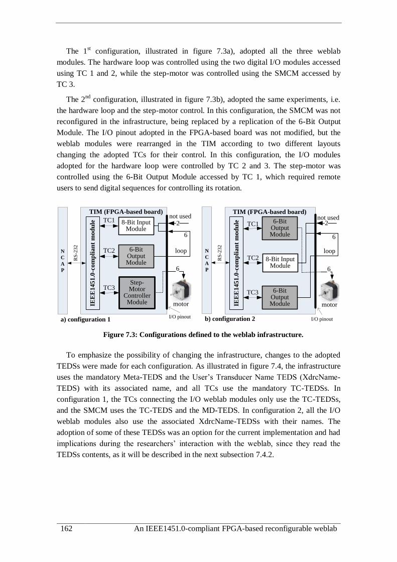
162 An IEEE1451.0-compliant FPGA-based reconfigurable weblab
The 1st configuration, illustrated in figure 7.3a), adopted all the three weblab
modules. The hardware loop was controlled using the two digital I/O modules accessed
using TC 1 and 2, while the step-motor was controlled using the SMCM accessed by
TC 3.
The 2nd
configuration, illustrated in figure 7.3b), adopted the same experiments, i.e.
the hardware loop and the step-motor control. In this configuration, the SMCM was not
reconfigured in the infrastructure, being replaced by a replication of the 6-Bit Output
Module. The I/O pinout adopted in the FPGA-based board was not modified, but the
weblab modules were rearranged in the TIM according to two different layouts
changing the adopted TCs for their control. In this configuration, the I/O modules
adopted for the hardware loop were controlled by TC 2 and 3. The step-motor was
controlled using the 6-Bit Output Module accessed by TC 1, which required remote
users to send digital sequences for controlling its rotation.
8-Bit Input Module
TIM (FPGA-based board)
IEE
E1451
.0-c
om
pli
an
t m
od
ule 8-Bit Input
Module
TC12
TIM (FPGA-based board)
6-Bit Output Module
Step-Motor
Controller Module
loopTC2
TC3
6
6
TC1
TC2
TC3
a) configuration 1 b) configuration 2
motor IEE
E1451
.0-c
om
pli
an
t m
od
ule 6-Bit
Output Module
6-Bit Output Module
2
loop
6
6
motor
not usednot used
N
C
A
P
N
C
A
P
I/O pinout I/O pinout
RS
-232
RS
-232
Figure 7.3: Configurations defined to the weblab infrastructure.
To emphasize the possibility of changing the infrastructure, changes to the adopted
TEDSs were made for each configuration. As illustrated in figure 7.4, the infrastructure
uses the mandatory Meta-TEDS and the User’s Transducer Name TEDS (XdrcName-
TEDS) with its associated name, and all TCs use the mandatory TC-TEDSs. In
configuration 1, the TCs connecting the I/O weblab modules only use the TC-TEDSs,
and the SMCM uses the TC-TEDS and the MD-TEDS. In configuration 2, all the I/O
weblab modules also use the associated XdrcName-TEDSs with their names. The
adoption of some of these TEDSs was an option for the current implementation and had
implications during the researchers’ interaction with the weblab, since they read the
TEDSs contents, as it will be described in the next subsection 7.4.2.
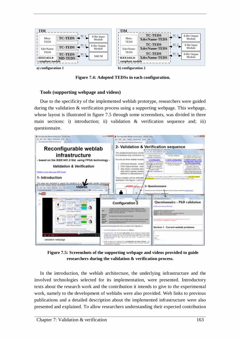
Chapter 7: Validation & verification 163
8-Bit Input Module
TC 1
TIM
SMCM
Meta-
TEDS
XdrcName-
TEDS
TC-TEDS
8-Bit Output Module
TC 2TC-TEDS
TC-TEDSMD-TEDS
TC 3
IEEE1451.0-
compliant module
TIM
Meta-
TEDS
XdrcName-
TEDS
8-Bit Input Module
TC 2
TC 3
IEEE1451.0-
compliant module
8-Bit Output Module
TC-TEDSXdrcName-TEDS
TC-TEDSXdrcName-TEDS
TC 1 8-Bit Output Module
TC-TEDSXdrcName-TEDS
a) configuration 1 b) configuration 2
Figure 7.4: Adopted TEDSs in each configuration.
Tools (supporting webpage and videos)
Due to the specificity of the implemented weblab prototype, researchers were guided
during the validation & verification process using a supporting webpage. This webpage,
whose layout is illustrated in figure 7.5 through some screenshots, was divided in three
main sections: i) introduction; ii) validation & verification sequence and; iii)
questionnaire.
videos
Figure 7.5: Screenshots of the supporting webpage and videos provided to guide
researchers during the validation & verification process.
In the introduction, the weblab architecture, the underlying infrastructure and the
involved technologies selected for its implementation, were presented. Introductory
texts about the research work and the contribution it intends to give to the experimental
work, namely to the development of weblabs were also provided. Web links to previous
publications and a detailed description about the implemented infrastructure were also
presented and explained. To allow researchers understanding their expected contribution

164 An IEEE1451.0-compliant FPGA-based reconfigurable weblab
in this process, the three main objectives defined in the previous section, and the two
main issues to explore, were clearly defined right from the start. These objectives focus
on: i) reconfiguring the infrastructure with different modules using the RecTool and; ii)
controlling those same modules using a set of IEEE1451.0 commands issued through
the IEEE1451.0-HTTP API. Since all invited researchers were more familiar with
software than hardware architectures, a set of texts about the IEEE1451.0 Std. and
FPGAs were suggested for consultation before proceeding with the validation &
verification process. Additionally, researchers were explained how they could issue
commands through a set of buttons, monitor the messages through internal status
registers, and restart the infrastructure in case it enters in a dead-lock state. In all these
interactions they were able to issue IEEE1451.0 commands using the message format
headers defined in the IEEE1451.0-HTTP API.
In the validation & verification section, the two different configurations applied to
the weblab infrastructure were presented and detailed through illustrative diagrams. A
table was provided with a methodology involving the phases followed by the
researchers to validate and verify the weblab, which includes reconfiguring, verifying,
and controlling the weblab modules adopted to interact with the target experiments.
While the reconfiguration was made using the RecTool, the verification and the control
were made through IEEE1451.0 commands. Since the current weblab prototype does
not provide GUIs for controlling the weblab modules reconfigured in the weblab
infrastructure, and it was not expected researchers to understand all the details of the
IEEE1451.0 Std., the commands used to control the reconfigured weblab modules were
previously selected and pre-defined. These commands were issued using interfaces
similar to the one illustrated in figure 7.6 that provides: i) a window with a set of
buttons that when pressed issue a particular command; ii) a command window that
presents the HTTP message format header adopted to send the command; iii) a reply
window that presents all replies in a XML format, whose schema is in accordance with
the IEEE1451.0 Std. and; iv) a button to clear the reply window. Additionally, to
complement this section, the execution of the involved stages was demonstrated through
a set of videos120
. They were uploaded to the YouTube platform so the researchers may
observe the different stages they should follow to interact with the weblab.
For getting the researchers’ opinions, a questionnaire was provided in the third
section of the supporting webpage divided in three parts, namely: i) current weblab
problems; ii) operation of the implemented weblab and; iii) relevance of the proposed
weblab architecture. Parts one and three of the questionnaire mainly focus on validating
the innovative solution, while part two focus on verifying if the current implementation
runs correctly. All these parts provided grid questions, where researchers may select
their accordance with specific statements, and open questions where they can express
their opinions.
120 The videos were created using the CamStudio software (http://camstudio.org/) and can be
consulted in the DVD annex to this thesis.

Chapter 7: Validation & verification 165
Predefined
IEEE1451.0 HTTP
commands
Reply
window Command
window
Clears windows contents
Figure 7.6: Typical interface adopted for issuing IEEE1451.0 commands using the
IEEE1451.0-HTTP API.
Therefore, researchers were guided during the interaction with the weblab, without
the need for understanding all the details of the IEEE1451.0 Std., which could make the
process too complex. The specificity of the implemented weblab infrastructure, which
involves several technologies and a particular architecture, required researchers to
follow the methodology presented in section two of the supporting webpage, which
comprises a set of sequential phases each with its particular objective.
Annex M.1 presents the main page of the supporting webpage, annex M.2 some
screenshots with videos exemplifying the interaction with the weblab, and annex M.3
the questionnaire provided to the researchers during the validation & verification
process.
7.3. Applied methodology
The adopted methodology to validate & verify the implemented weblab comprises
three phases, which include the sequence illustrated in figure 7.7 in order to: i)
(re)configure the weblab infrastructure according to the described layouts; ii) verify
those (re)configurations and; iii) control the weblab modules.
1st configuration Verify 1st configurationModules’ control
(1st configuration)
2nd configuration
(reconfiguration)
Verify
2nd configuration
Modules’ control
(2nd configuration)
phase 1 phase 3phase 2
Figure 7.7: Phases adopted for the researchers’ interaction with the weblab.
During the 1st phase, researchers used the RecTool. They selected a set of predefined
files that define each weblab module, plus the files required to configure the

166 An IEEE1451.0-compliant FPGA-based reconfigurable weblab
infrastructure. Using the RecTool, those files were uploaded to the weblab server
defining a new layout for the infrastructure. To verify if the configuration process was
running correctly during this phase, researchers were able to consult the reports
automatically generated by the RecTool.
In the 2nd
phase, researchers issued a set of IEEE1451.0 commands to the weblab, in
order to verify if the configuration made in the previous phase was really successfully
applied to the infrastructure. For this purpose, researchers issued ReadRawTEDS
commands to read a set of TEDSs from each configuration. The associated replies
retrieved all data of the selected TEDSs, so researchers could understand that a specific
configuration was available in the weblab. All commands’ headers were predefined with
a set of parameters that specify the target TC, the TEDSs, the XML format reply, and
others; this way reducing the inherent complexity involved in this process.
The 3rd
phase comprehended the access/control of the weblab modules, and
consequently of the target experiments. This phase was divided in two sections. The
first to the hardware loop control and the second to the step-motor control. The
hardware loop control used write and read commands, namely the IEEE1451.0
Write/ReadTCDSsegment commands, since both configurations adopted the same I/O
weblab modules. The difference was the interface with the IEEE1451.0-compliant
module, since those modules were bound through different TCs to verify the
reconfiguration capability of the infrastructure. The step-motor control was made in a
distinct way for each configuration and, due to the specificity of this type of experiment,
users were able to visualize its axis through captured webcam video frames121
available
in the supporting webpage, as represented in figure 7.8.
Figure 7.8: Picture of the adopted step-motor and video frame of its axis provided by
the supporting webpage.
In configuration one, the step-motor was controlled using the SMCM, whose
operation is defined through a MD-TEDS. Researchers were able to read and write
121 The webcam was connected to an USB port of the weblab server and streamed the video frames
using the MJPG-streamer software (http://sourceforge.net/projects/mjpg-streamer/).

Chapter 7: Validation & verification 167
specific fields of this TEDS, before starting the step-motor rotation. As represented on
the sequence of figure 7.9, a set of commands were issued using the methods of the
IEEE1451.0-HTTP API to verify the possibility of using the IEEE1451.0 Std. to control
the step-motor. Researchers were invited to use the ReadRawTEDS method whenever they
wanted to read the current MD-TEDS configuration. Initially, the SMCM had a
particular configuration that forces the step-motor to rotate continuously in a specific
direction at a speed of 4 steps/s. Researchers started the rotation of the step-motor by
sending a trigger signal to the SMCM using the StartTrigger method and stopped its
rotation using the StopTrigger method. These methods were able to be issued any time
researchers wanted to. After testing the continuous rotation of the step-motor,
researchers updated the MD-TEDS’s fields using the WriteTEDS and UpdateTEDS
commands issued by the SendCommand method of the IEEE1451.0-HTTP API. The new
MD-TEDS configuration forced the step-motor to rotate one turn (400 steps) at a speed
of 400 steps/s after each received trigger using the StartTrigger method. All commands
were issued and the replies monitored using methods of the IEEE1451.0-HTTP API,
similar to the one presented in previous figure 7.6.
Start continous step-motor rotation
(triggerCommand)
Stop rotation(stopTrigger)
Update MD-TEDS(WriteTEDS & UpdateTEDS)
Start one step-motor rotation
(triggerCommand)
SMCM operation changed.
MD-TEDS: 400 steps, speed=400 steps/s
Stop rotation(stopTrigger)
MD-TEDS was suggested to read
whenever researchers want to
(ReadRawTEDS)
Default SMCM operation.
MD-TEDS: infinite steps & speed=4 steps/s
end
init
Figure 7.9: Command sequence applied to control the step-motor rotation in the 1st
configuration.
In configuration two, the step-motor was controlled through the 6-Bit Output
Module. This required introducing the basis of step-motor control through a small text
and through an illustration in the supporting webpage. By consulting these resources,
researchers (at least the ones not familiar with this type of control) were able to
understand the reason for sending a set of code sequences to energize the coils of the
step-motor, so it could rotate through half-steps. These sequences were sent, using the
WriteDataSetSegment command sequentially, to rotate the motor in the same direction.
Once concluded the interaction with the weblab, the involved researchers filled-in
the questionnaire, providing their opinions about the implemented weblab prototype and
its added value to the experimental work in engineering education.
Examples of webpages with the methodology provided in 2nd
section of the
supporting webpage are presented in annex M.4.
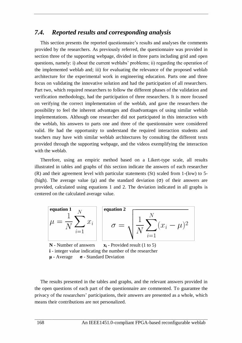
168 An IEEE1451.0-compliant FPGA-based reconfigurable weblab
7.4. Reported results and corresponding analysis
This section presents the reported questionnaire’s results and analyses the comments
provided by the researchers. As previously referred, the questionnaire was provided in
section three of the supporting webpage, divided in three parts including grid and open
questions, namely: i) about the current weblabs’ problems; ii) regarding the operation of
the implemented weblab and; iii) for evaluating the relevance of the proposed weblab
architecture for the experimental work in engineering education. Parts one and three
focus on validating the innovative solution and had the participation of all researchers.
Part two, which required researchers to follow the different phases of the validation and
verification methodology, had the participation of three researchers. It is more focused
on verifying the correct implementation of the weblab, and gave the researchers the
possibility to feel the inherent advantages and disadvantages of using similar weblab
implementations. Although one researcher did not participated in this interaction with
the weblab, his answers to parts one and three of the questionnaire were considered
valid. He had the opportunity to understand the required interaction students and
teachers may have with similar weblab architectures by consulting the different texts
provided through the supporting webpage, and the videos exemplifying the interaction
with the weblab.
Therefore, using an empiric method based on a Likert-type scale, all results
illustrated in tables and graphs of this section indicate the answers of each researcher
(R) and their agreement level with particular statements (St) scaled from 1-(low) to 5-
(high). The average value (μ) and the standard deviation (σ) of their answers are
provided, calculated using equations 1 and 2. The deviation indicated in all graphs is
centered on the calculated average value.
N - Number of answers xi - Provided result (1 to 5)
i - integer value indicating the number of the researcher
μ - Average σ - Standard Deviation
equation 1 equation 2
The results presented in the tables and graphs, and the relevant answers provided in
the open questions of each part of the questionnaire are commented. To guarantee the
privacy of the researchers’ participations, their answers are presented as a whole, which
means their contributions are not personalized.

Chapter 7: Validation & verification 169
7.4.1 Current weblabs’ problems
Table 7.1 and graph of figure 7.10 indicate the researchers’ accordance with six pre-
selected problems faced by weblabs, specified through 6 statements.
Table 7.1: Accordance with six problems currently faced by weblabs.
R1 R2 R3 R4 μ σ
1 There is a lack of standards for developing weblab
architectures. 3 4 2 3 3 0,71
2 There is a lack of standards to access weblab modules. 4 5 5 4 4,5 0,50
3 It is impossible to share/replicate weblab modules
through different infrastructures. 4 4 5 4 4,25 0,43
4
There is a low flexibility in current weblabs, which
difficults redesigning experiments using the same infrastructure.
4 4 5 4 4,25 0,43
5 Typically, the costs can be high for developing weblabs
and designing experiments. 4 5 4 4 4,25 0,43
6 There is a reduced collaboration among institutions in
the development of weblabs. 4 5 2 3 3,5 1,12
4,5
3
4,25 4,25 4,25
3,5
0,0
1,0
2,0
3,0
4,0
5,0
St1 St2 St3 St4 St5 St6
researcher 1 researcher 2 researcher 3 researcher 4 average [Std. deviation]
Figure 7.10: Graph results with the accordance with six problems currently faced by
weblabs.
Observing the results, it is evident that there is a general agreement that most of the
selected problems must be solved. However, most of the researchers do not consider the
lack of a standard architecture important, and the reduced collaboration among
institutions in the development of weblabs important, despite the divergence of their
answers. Rather, supported on further responses, the lack of standard interfaces is a
more relevant problem that should be solved briefly. One of the researchers even
defended that it is perfectly normal the existence of a diversity of architectures, since
different laboratories have different requirements and, therefore, distinct equipments.
The common idea to all is that weblabs in the future should follow a plugged&shared

170 An IEEE1451.0-compliant FPGA-based reconfigurable weblab
approach using friendly interfaces supported by standard APIs, despite they may use
different architectures.
Reusability, flexibility and scalability in the integration of weblabs are seen as
fundamental issues to improve. This can be done using standard APIs to access, share
and maintain weblab sessions independently of the implemented architecture. In this
domain, a researcher indicated the current efforts made on GOLC for defining a
standard description language to allow different systems (weblab management systems,
architectural repositories and other systems) to exchange information about their
installations. Providing a more reliable interaction with the experiments, giving to the
students/teachers the capability of managing connections like in traditional laboratories,
was also pointed as an issue to investigate, since it has implications in the pedagogical
aspect that still requires a special attention. The difficulty of sharing experiments among
institutions was also pointed out as an inherent problem caused by the lack of a standard
access to those weblabs, which has incentivized a recent research for creating a
federation model for remote laboratories [154].
7.4.2 Operation of the implemented weblab
With the contribution of three researchers, part two of the questionnaire focused on
verifying the implemented weblab, namely the control and the configuration of the
infrastructure with the weblab modules adopted for each experiment. This part was
divided in three sections, according to the methodology described in subsection 7.3 of
this thesis, namely: i) configurations; ii) verification of those configurations and; iii)
weblab modules’ control. The following tables and graphs provide the level of
accordance each researcher had with a set of statements, following the same
classification made for the previous table and graph.
In table 7.2 and graph of figure 7.11 five statements about the configuration phases
were classified. Observing the results, it can be seen that there was considerable
deviations in the answers, with one of the researchers giving low classifications to most
of the statements. It can be said that the RecTool interface was easily understood by two
of the researchers, while the other had some difficulties to understand all its details. One
of them indicated the simplicity of the design that may promote the users’ adoption and
experience, since all files and reports, generated during the reconfiguration process, are
located in a single and well organized interface. Another indicated that the layout can be
improved concerning usability issues, despite the added value it may bring for sharing
resources, namely the weblab modules. Nevertheless, some issues were suggested to
improve and some facilities did not run as expected. To overcome this difficulty, during
the configuration process some files were previously uploaded using the same RecTool
interface by accessing it through the same network where the weblab server was
running.

Chapter 7: Validation & verification 171
Table 7.2: Accordance with the configuration phases.
R1 R2 R3 μ σ
1 It was easy to configure the weblab infrastructure. 2 4 4 3,3 0,94
2 The layout of the RecTool interface was easy to use and
understand. 2 3 5 3,3 1,25
3 The reports provided were fundamental to verify the success
of each step. 3 5 5 4,3 0,94
4 It was ease to change the configuration of the weblab infrastructure.
2 4 4 3,3 0,94
5
The approach applied in the configuration steps is satisfactory
for designing remote experiments without changing the
infrastructure
3 4 4 3,7 0,47
Uploading several files one by one to the weblab server, was also a suggestion to
improve in future versions of the RecTool. Two of the researchers suggested that it will
be more user-friendly to send several files at once, per example, by concatenating them
into a single archive. This meant that uploading files to the weblab server was
considered the most difficult task during the reconfiguration process.
Some researchers also pointed the process of building the weblab project as a
difficult task. They reported some lack of information during this process, and the long
time spent, which took about 20 minutes to be concluded.
3,7
3,3
4,3
3,3 3,3
0,0
1,0
2,0
3,0
4,0
5,0
St1 St2 St3 St4 St5
researcher 1 researcher 2 researcher 3 average [Std. deviation]
Figure 7.11: Graph results with the accordance with the configuration phases.
It can be seen through statement three that, although some faced difficulties using the
RecTool for reconfiguring the weblab infrastructure, the reports provided during this
stage were useful. It was also evident that one of the researchers experienced more
difficulties than the others, but all of them concluded this stage successfully,
reconfiguring the infrastructure with the selected weblab modules.
Next step involved the verification of the configuration. Researchers sent several
IEEE1451.0 commands to the weblab and observed the replies in an XML format.

172 An IEEE1451.0-compliant FPGA-based reconfigurable weblab
Divided according to generic and particular issues of each configuration, table 7.3 and
the graph of figure 7.12 present their agreement with nine statements.
Table 7.3: Accordance with the verify configuration phases.
R1 R2 R3 μ σ
1
After configuring the weblab I sent several IEEE1451.0
commands and the replies were useful to verify the correct
configuration of the weblab infrastructure.
3 4 5 4,0 0,82
2
I feel that if I understand all details of the IEEE1451.0 Std. the replies returned from the issued commands will be better
understood.
2 5 5 4,0 1,41
3
In configuration 1 I easily got the expected result after issuing
the ReadRawTEDS [XdrcName-TC1], i.e, an error
code=24599 indicating that the weblab module controlled by
TC1 does not had any associated XdrcName TEDS.
4 4 5 4,3 0,47
4 In configuration 1 I easily got the expected result after issuing
the ReadRawTEDS [Meta-TEDS]. 4 4 4 4,0 0,00
5 In configuration 1 I easily got the expected result after issuing
the ReadRawTEDS [MD-TEDS]. 4 4 5 4,3 0,47
6
In configuration 2 I easily got the names of all weblab
modules after issuing the ReadRawTEDS [XdrcName-TCx]
commands.
3 4 5 4,0 0,82
7 In configuration 2 I easily got the expected result after issuing
the ReadRawTEDS [Meta-TEDS]. 4 4 4 4,0 0,00
8
In configuration 2 I easily got the expected result after issuing
the ReadRawTEDS [MD-TEDS], i.e, an error code=24599
indicating that the weblab module controlled by TC3 does not
had any associated MD-TEDS.
4 5 5 4,7 0,47
9
In configuration 2 the results retrieved after issuing
IEEE1451.0 commands indicated me clearly that the weblab
has a new configuration.
2 5 5 4,0 1,41
4,0
4,7
4,04,04,0
4,3
4,0
4,3
4,0
0,0
1,0
2,0
3,0
4,0
5,0
St1 St2 St3 St4 St5 St6 St7 St8 St9
researcher 1 researcher 2 researcher 3 average [Std. deviation]
generic configuration 1 configuration 2
Figure 7.12: Graph results with the accordance with the verify configuration phases.

Chapter 7: Validation & verification 173
Despite the deviations on statements two and nine, caused by the answers of one
researcher, it can be said that the results were satisfactory, which means all researchers
were able to verify that the weblab infrastructure was reconfigured as expected,
according to the replies retrieved from the TEDSs read after each configuration. To
more easily interpret the information that was retrieved as a raw of data, it was
suggested the development of an interface to provide the information in a more human
readable fashion. Improvements to the communication between the NCAP and TIM
were also suggested, since the infrastructure reported some errors in the reply messages
after sending some commands, which justifies the average classification of 4 in both
configurations. As in the previous phase, it was also evident that, during this process,
one of the researchers experienced more difficulties than the others.
Table 7.4 and figure 7.13 report the researchers’ opinions about the interaction with
the weblab modules using IEEE1451.0 commands for each configuration and target
experiment. Eight statements were provided.
Despite the satisfactory answers regarding the control of each experiment in both
configurations, some difficulties were reported, in particular by one of the researchers,
which justify some of the deviations on the results. The control of the step-motor in
configuration one was considered easier than in configuration two, since a single trigger
started the rotation of the motor. Some errors were pointed when sending
WriteTCDSsegment commands to the weblab, namely to the I/O modules, which
justifies the lowest classification of statements one and three in the graph. This was
evident regarding the step-motor control rotation in the second configuration, since it
required sending several step-codes to the output module to rotate the motor through
half-steps. Moreover, some difficulties were referred when observing the rotation of the
motor using the axis image available in the supporting webpage, since each half-step
corresponds to a very small rotation of 0.9º.
Table 7.4: Accordance with the weblab modules’ control.
R1 R2 R3 μ σ
1 In configuration 1 it was easy to control the I/O modules. 3 4 4 3,7 0,47
2 In configuration 1 the retrieved replies during the control of
the I/O modules were satisfactory. 4 5 5 4,7 0,47
3 In configuration 2 it was easy to control the I/O Modules. 3 4 4 3,7 0,47
4 In configuration 2 the retrieved replies during the control of
the I/O modules were satisfactory. 4 4 5 4,3 0,47
5 In configuration 1 the control of the step-motor was easy to
do using the SMCM. 4 5 5 4,7 0,47
6
In configuration 1 the ability of redefining the MD-TEDS of
the SMCM to control the step-motor is an interesting solution
for controlling every type of weblab module.
4 5 5 4,7 0,47
7
In configuration 1 the use of the ReadRawTEDS [MD-TEDS]
command gave me a concrete understanding that I was
changing the contents of the MD-TEDS.
3 5 5 4,3 0,94
8 In configuration 2 it was easy to control the step-motor using the output module.
3 5 4 4,0 0,82
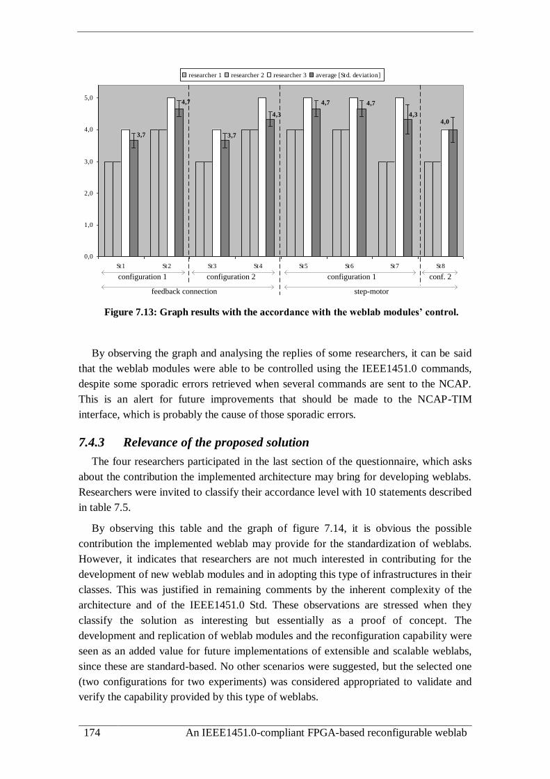
174 An IEEE1451.0-compliant FPGA-based reconfigurable weblab
4,74,7
4,3
3,73,7
4,7
4,34,0
0,0
1,0
2,0
3,0
4,0
5,0
St1 St2 St3 St4 St5 St6 St7 St8
researcher 1 researcher 2 researcher 3 average [Std. deviation]
configuration 1 configuration 1configuration 2 conf. 2
feedback connection step-motor
Figure 7.13: Graph results with the accordance with the weblab modules’ control.
By observing the graph and analysing the replies of some researchers, it can be said
that the weblab modules were able to be controlled using the IEEE1451.0 commands,
despite some sporadic errors retrieved when several commands are sent to the NCAP.
This is an alert for future improvements that should be made to the NCAP-TIM
interface, which is probably the cause of those sporadic errors.
7.4.3 Relevance of the proposed solution
The four researchers participated in the last section of the questionnaire, which asks
about the contribution the implemented architecture may bring for developing weblabs.
Researchers were invited to classify their accordance level with 10 statements described
in table 7.5.
By observing this table and the graph of figure 7.14, it is obvious the possible
contribution the implemented weblab may provide for the standardization of weblabs.
However, it indicates that researchers are not much interested in contributing for the
development of new weblab modules and in adopting this type of infrastructures in their
classes. This was justified in remaining comments by the inherent complexity of the
architecture and of the IEEE1451.0 Std. These observations are stressed when they
classify the solution as interesting but essentially as a proof of concept. The
development and replication of weblab modules and the reconfiguration capability were
seen as an added value for future implementations of extensible and scalable weblabs,
since these are standard-based. No other scenarios were suggested, but the selected one
(two configurations for two experiments) was considered appropriated to validate and
verify the capability provided by this type of weblabs.
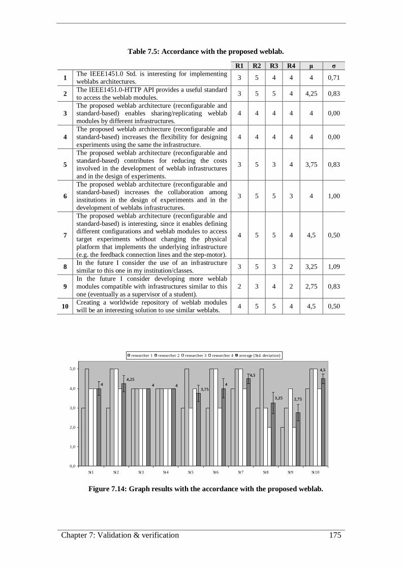
Chapter 7: Validation & verification 175
Table 7.5: Accordance with the proposed weblab.
R1 R2 R3 R4 μ σ
1 The IEEE1451.0 Std. is interesting for implementing
weblabs architectures. 3 5 4 4 4 0,71
2 The IEEE1451.0-HTTP API provides a useful standard
to access the weblab modules. 3 5 5 4 4,25 0,83
3
The proposed weblab architecture (reconfigurable and standard-based) enables sharing/replicating weblab
modules by different infrastructures.
4 4 4 4 4 0,00
4
The proposed weblab architecture (reconfigurable and
standard-based) increases the flexibility for designing
experiments using the same the infrastructure.
4 4 4 4 4 0,00
5
The proposed weblab architecture (reconfigurable and
standard-based) contributes for reducing the costs
involved in the development of weblab infrastructures
and in the design of experiments.
3 5 3 4 3,75 0,83
6
The proposed weblab architecture (reconfigurable and
standard-based) increases the collaboration among
institutions in the design of experiments and in the
development of weblabs infrastructures.
3 5 5 3 4 1,00
7
The proposed weblab architecture (reconfigurable and
standard-based) is interesting, since it enables defining different configurations and weblab modules to access
target experiments without changing the physical
platform that implements the underlying infrastructure
(e.g. the feedback connection lines and the step-motor).
4 5 5 4 4,5 0,50
8 In the future I consider the use of an infrastructure
similar to this one in my institution/classes. 3 5 3 2 3,25 1,09
9
In the future I consider developing more weblab
modules compatible with infrastructures similar to this
one (eventually as a supervisor of a student).
2 3 4 2 2,75 0,83
10 Creating a worldwide repository of weblab modules
will be an interesting solution to use similar weblabs. 4 5 5 4 4,5 0,50
4
3,75444
4,254,5
3,25 2,75
4,5
0,0
1,0
2,0
3,0
4,0
5,0
St1 St2 St3 St4 St5 St6 St7 St8 St9 St10
researcher 1 researcher 2 researcher 3 researcher 4 average [Std. deviation]
Figure 7.14: Graph results with the accordance with the proposed weblab.

176 An IEEE1451.0-compliant FPGA-based reconfigurable weblab
At the end of this questionnaire, researchers were invited to give their opinions about
the advantages and disadvantages this weblab may bring to the human actors described
in chapter 2. The weblab was classified as interesting for students, since it provides
standard and transparent access to the weblab modules, approaching its characteristics
to hands-on laboratories (traditional laboratories) that allow redefining experiments
using different instrumentation. However, since students should only focus on the
experiment itself, the reconfiguration process was considered as a possible difficulty.
One of the researchers even reported that reconfiguration could be interesting if the
target experiments involved learning how to program FPGAs, otherwise it should be
skipped, due to the inherent complexity. This consideration highlights the importance of
simplifying the reconfiguration process for future weblab architectures supported on
FPGA technology.
The capabilities of designing, sharing and interacting with the weblab modules
adopted in particular experiments, were considered issues able to be fulfilled by this
type of weblabs and an inherent advantage for teachers. These are the responsible for
designing new experiments, and the current capabilities of the weblab give them the
possibility to prepare new students’ experimental activities involving new layouts. A
researcher also stressed that this weblab could be useful as a support for theoretical
lessons that involves the study of FPGAs as a topic.
Developers were described as the most profit actors, since they can replicate
experiments and reuse the modules. Nevertheless, the difficulty of developing new
modules was considered as a probable hard task, since they should have very particular
skills and knowledge about the implemented infrastructure. Questions related to the
scalability and to the integration of this weblab with others already implemented, were
again stressed by one of the researchers, as an issue that should be solved and
investigated.
The correct weblab operation, traditionally ensured by technicians, was classified as
a possible drawback due to the specificity of the weblab modules (that comprises
several files and involves a specific reconfiguration process). This justifies that in this
type of laboratory one of the researchers defended that technicians should take the role
of the administrators, due to the inherent complexity of the infrastructure, which
requires some skills that go behind the IT specialization of a traditional administrator.
7.5. Summary
This chapter described a validation & verification process of the implemented
weblab architecture and underlying infrastructure described in previous chapters 5 and
6. It had the contribution of four researchers with large experience and expertise in the
development of weblabs, contributing with valuable opinions about the overall
functionalities of the implemented architecture and, in particular, the use of the
Chapter 7: Validation & verification 177
IEEE1451.0 Std. and FPGA technology for designing standard-based and
reconfigurable weblabs.
Researchers were able to reconfigure the weblab infrastructure with a set of weblab
modules using the RecTool. They define two distinct configurations to the weblab
infrastructure using three pre-defined weblab modules to control two experiments. In
these configurations the weblab modules were embedded into the infrastructure using
different layouts, being one of the modules replicated without further developments.
By using IEEE1451.0 commands issued through the IEEE1451.0-HTTP API, both
configurations were verified and the weblab modules accessed to conduct the two
adopted experiments. Due to the specificity of the implemented weblab, a set of tools
were provided to guide researchers through the entire validation & verification process.
The most important one was the supporting webpage that detailed the implemented
weblab, presented the methodology with the different stages followed by the
researchers, and provided the questionnaire that was filled-in at the end of the validation
& verification process. A particular relevance to the methodology described in the
supporting webpage, complemented with some illustrative videos, was made, since it
describes the different stages followed by the researchers during the interaction with the
weblab. At the end, this chapter presented the results obtained from the questionnaire,
and provided some comments that indicate the valuable and promising contribution this
type of low-cost, standard-based and reconfigurable weblabs may bring to the
experimental work in engineering education.
178 An IEEE1451.0-compliant FPGA-based reconfigurable weblab

Chapter 8: Conclusions and future work 179
Chapter 8
Conclusions and future work
This chapter provides the conclusions about the work described in this thesis,
emphasizing its innovative aspects and the implications for engineering education.
Future work perspectives and some concluding remarks close the chapter.

180 An IEEE1451.0-compliant FPGA-based reconfigurable weblab
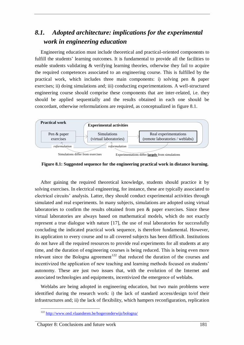
Chapter 8: Conclusions and future work 181
8.1. Adopted architecture: implications for the experimental
work in engineering education
Engineering education must include theoretical and practical-oriented components to
fulfill the students’ learning outcomes. It is fundamental to provide all the facilities to
enable students validating & verifying learning theories, otherwise they fail to acquire
the required competences associated to an engineering course. This is fulfilled by the
practical work, which includes three main components: i) solving pen & paper
exercises; ii) doing simulations and; iii) conducting experimentations. A well-structured
engineering course should comprise these components that are inter-related, i.e. they
should be applied sequentially and the results obtained in each one should be
concordant, otherwise reformulations are required, as conceptualized in figure 8.1.
Pen & paper
exercises
Simulations
(virtual laboratories)
Real experimentations
(remote laboratories / weblabs)
Experimental activitiesPractical work
Experimentations differ largely from simulationsSimulations differ from exercises
reformulation reformulation
Figure 8.1: Suggested sequence for the engineering practical work in distance learning.
After gaining the required theoretical knowledge, students should practice it by
solving exercises. In electrical engineering, for instance, these are typically associated to
electrical circuits’ analysis. Latter, they should conduct experimental activities through
simulated and real experiments. In many subjects, simulations are adopted using virtual
laboratories to confirm the results obtained from pen & paper exercises. Since these
virtual laboratories are always based on mathematical models, which do not exactly
represent a true dialogue with nature [17], the use of real laboratories for successfully
concluding the indicated practical work sequence, is therefore fundamental. However,
its application to every course and to all covered subjects has been difficult. Institutions
do not have all the required resources to provide real experiments for all students at any
time, and the duration of engineering courses is being reduced. This is being even more
relevant since the Bologna agreement122
that reduced the duration of the courses and
incentivized the application of new teaching and learning methods focused on students’
autonomy. These are just two issues that, with the evolution of the Internet and
associated technologies and equipments, incentivized the emergence of weblabs.
Weblabs are being adopted in engineering education, but two main problems were
identified during the research work: i) the lack of standard access/design to/of their
infrastructures and; ii) the lack of flexibility, which hampers reconfiguration, replication
122 http://www.ond.vlaanderen.be/hogeronderwijs/bologna/

182 An IEEE1451.0-compliant FPGA-based reconfigurable weblab
and sharing of different weblab modules for conducting a particular experiment. The
lack of standardization is mainly a problem associated to the design of weblabs, that
influence their (non-)adoption in a particular course. The lack of flexibility for using the
weblab modules, besides reducing collaboration during the design of weblabs and of the
associated experiments, also difficults attaining design and psychomotor objectives
indicated as fundamental by ABET for every engineering course123
. To contribute for
solving these problems, seeking always for a cost-effective solution, the research work
done was supported by two main issues:
the evaluation of the IEEE1451.0 Std. for designing standard weblab
architectures and underlying infrastructures, and;
the adoption of reconfigurable technology, namely FPGAs, for enabling the
reconfiguration of the infrastructure with weblab modules, described and
accessed according to the IEEE1451.0 Std.
The IEEE1451.0 Std. features were considered appropriated to implement weblabs,
since this standard specifies different layers for network-interfacing, accessing and
designing the so-called smart transducers. Due to their internal structure and the ability
for implementing smart operations, these transducers were seen as the weblab modules
required to conduct remote experiments. By joining the IEEE1451.0 Std. features and
the reconfiguration capabilities provided by FPGAs, a weblab architecture was
conceived and implemented, enabling the reconfiguration of weblab modules in its
underlying infrastructure.
The implemented weblab was a consequence of the conducted research in the
domain of weblabs that led to new suggestions and implementations based on the
IEEE1451.0 Std. and FPGA technology. Besides contextualizing the role of weblabs in
engineering education (chapter 2), the research work focused on technical issues about
their architectures and underlying infrastructures. Some considerations were provided
about the traditional solutions and on-going initiatives for standardizing the
implementation of weblabs (chapter 3). After a brief overview of the possibility and
relevance for using the IEEE1451.0 Std. and FPGAs in the design of weblabs (chapter
3), new and innovative aspects were described and implemented during the remaining
work, namely:
new weblab infrastructures based on the NCAP-TIM reference model of the
IEEE1451.0 Std. (chapter 4);
new extensions to the IEEE1451.0 Std. (chapter 4);
123 The 13 learning objectives established for addressing the role of laboratories in engineering
education are detailed and commented in section 2.4.1 of this document.

Chapter 8: Conclusions and future work 183
a reconfigurable weblab supported on the reconfiguration capabilities of FPGAs
and on the proposed extensions for the IEEE1451.0 Std., which includes a thin-
implementation for its reference model (chapter 5);
an IEEE1451.0-compliant module developed in Verilog HDL to implement part
of the TIM, and an NCAP to enable its remote access (chapter 5 and 6);
a layout and an interface for designing and binding the weblab modules to the
IEEE1451.0-compliant module (four weblab modules were described according
to a conceived layout and interface) (chapter 6);
a reconfiguration tool and a methodology to facilitate the reconfiguration of
those weblab modules into the infrastructure (chapter 5 and 6), and;
a validation & verification methodology applied to the implemented weblab,
involving a number of worldwide recognized experts in weblabs design (chapter
7).
The previous suggestions and implementations, and the researchers’ opinions
described and commented in chapter 7, support the claim that this type of standard-
based and reconfigurable weblabs may contribute for the widespread of weblabs in
engineering education. The possibility of having a unique weblab infrastructure able to
accommodate different weblab modules facilitates the design of experiments without
further developments. In many weblabs, when a new experiment is provided, the
required weblab modules are locally changed in the infrastructure. A technician must go
to the infrastructure and replace them to conduct a particular experiment. Currently,
some weblabs facilitate this task by providing several weblab modules in the
infrastructure so users (teachers, students and technicians) may remotely setup the
infrastructure by establishing the required connections between the target experiments
and the required weblab modules [70][53][155]. The proposed weblab solution
improves this feature by enabling the total replacement of the weblab modules in the
underlying infrastructure. Since these modules are essentially described through
standard Verilog HDL files, they can be easily shared and replicated, which facilitates
setting-up the infrastructure for conducting the target experiments and contributes for a
drastic reduction in weblabs development costs.
Currently, the use of FPGAs for implementing the reconfigurable weblab
infrastructure is seen as the most appropriated technology to accommodate the weblab
modules. However, technology is always changing, and other types of devices can be
considered in the future. It is important to highlight that the description of the weblab
modules through files using the standard Verilog HDL guarantees their reutilization in
different types of FPGAs and, eventually, in other reconfigurable devices that may be
adopted. This reconfiguration and the facility of sharing the weblab modules is only
efficient because the proposed and developed weblab architecture, the underlying

184 An IEEE1451.0-compliant FPGA-based reconfigurable weblab
infrastructure and the weblab modules are accessed and developed according to the
IEEE1451.0 Std.
The access is made through standard commands, using the IEEE1451.0-HTTP API.
The importance of having standard commands issued by a standard API is especially
important for the adoption of weblabs in engineering education, since this is another
main problem reported by the research community. Traditionally, weblabs use their own
APIs, which hampers collaboration among institutions since different weblabs require
different types of access to the underlying infrastructure and to the weblab modules,
thus difficulting the share of experiments, tools and resources. The use of the
IEEE1451.0 Std. overcomes this problem. By using the IEEE1451.0-HTTP API, the
widespread of weblabs in engineering education and the collaboration among
institutions in the development and share of their own experiments is incentivized. More
standard tools and resources can be developed, per example, for assessment purposes to
evaluate the conduction of a particular experiment by monitoring the command and
reply messages exchanged between the users and the experiments.
The developments were made according to the specifications defined in the standard.
Besides using a NCAP-TIM thin implementation, the use of TEDSs is an advantage for
adopting the IEEE1451.0 Std. for designing these types of weblabs. TEDSs specify the
operation and characteristics of each weblab, providing information about the
infrastructure and the reconfigured weblab modules. Remote users may then understand
the characteristics of a particular infrastructure and of each weblab module by issuing
standard commands. The conducted research also suggested an architecture supported
by the new LabTEDS, which evidences the relevance of this type of data structures for
designing standard weblab architectures. By using the architecture supported by the
LabTEDS, the dissemination of weblabs through the educational community can be
improved, since it provides information about a particular weblab, what kind of
experiments they provide, the resources adopted by the underlying infrastructures,
among others.
The weblab modules were developed according to the IEEE1451.0 Std., which
incentivize their share through distinct compatible infrastructures and the collaboration
among the developers. By using the developed IEEE1451.0-compliant module the
weblab modules can be accessed and accommodated into distinct weblab infrastructures
without further developments. Traditional infrastructures, which can be expensive with
specific and unnecessary features for running some experiments, can now be
reconfigured with dedicated, pre-defined and cost-effective modules.
Therefore, the proposed solution based on the IEEE1451.0 Std. and FPGA
technology, can be seen as an important contribution for using weblabs in engineering
education. The costs can be largely reduced and the collaboration among institutions in
sharing experiments and modules, and during the developments, can be increased.

Chapter 8: Conclusions and future work 185
8.2. Future work perspectives
During the research and the developments described in this thesis, it became evident
the involved complexity for creating a standard-based and reconfigurable weblab.
Despite the broad range covered by the IEEE1451.0 Std., it involves too many
possibilities and layers that require extensive developments to adopt all of them in the
design of weblab infrastructures. It was precisely this complexity that incentivized the
description and the adoption of a thin implementation of the IEEE1451.0 Std. reference
model for the design of a reconfigurable weblab infrastructure.
The adopted solution for reconfiguring the weblab infrastructure separates, as much
as possible, the features described by the IEEE1451.0 Std. from the features associated
to each weblab module. During the reconfiguration process, the IEEE1451.0-compliant
module is redefined according to a specific methodology using a reconfiguration tool, as
described in sections 5.5 and 6.4. This tool automatically reconfigures the weblab
infrastructure binding the modules according to a set of complex files difficult to be
defined by teachers and students, namely the TEDSs, the map and the configuration
files. Since their definition requires particular knowledge about the standard and the
implemented infrastructure, namely about the IEEE1451.0-compliant module, a tool to
facilitate their specification is currently being developed by an MSc. student, as
illustrated in figure 8.2. However, more efforts are required to simplify this process,
since the interfaces still require detailed knowledge about the implemented weblab and
about the IEEE1451.0 Std. The development of a graphical tool, where users
transparently bind the weblab modules to the infrastructure, is certainly a topic of future
development and research.
A complementary solution would be the improvement and the simplification of the
entire reconfiguration process. According to the validation & verification process
described in chapter 7, this step was considered complex and too much time consuming.
Since the reconfigurable infrastructure was implemented on FPGA technology, this
issue is currently difficult to simplify, essentially because of the inherent complexity for
synthesizing HDL files, such as the ones that describe the weblab project. With the
evolution of FPGA technology or using other types of reconfigurable devices, this issue
should be further analysed. The current solution adopts FPGAs with total
reconfiguration rather then partial reconfiguration. This option was made since binding
the weblab modules to the IEEE1451.0-compliant module requires its internal
redefinition (number of TCs, adopted buses, etc.), and therefore a new synthesis,
whenever a different weblab module is bound. The use of automatic routing
mechanisms to bind the weblab modules to a pre-defined IEEE1451.0-compliant
module, previously synthesized and embedded in the FPGA, can be an issue to explore
in future implementations. For now, current FPGA tools for routing HDL modules
inside their cores are too manufacturer dependent and require a manual control, which
makes it impracticable for an automatic reconfiguration.
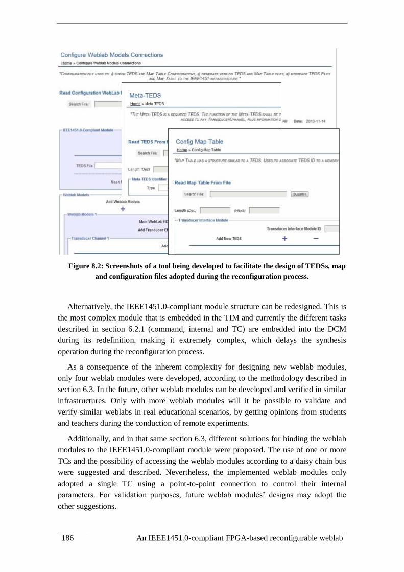
186 An IEEE1451.0-compliant FPGA-based reconfigurable weblab
Figure 8.2: Screenshots of a tool being developed to facilitate the design of TEDSs, map
and configuration files adopted during the reconfiguration process.
Alternatively, the IEEE1451.0-compliant module structure can be redesigned. This is
the most complex module that is embedded in the TIM and currently the different tasks
described in section 6.2.1 (command, internal and TC) are embedded into the DCM
during its redefinition, making it extremely complex, which delays the synthesis
operation during the reconfiguration process.
As a consequence of the inherent complexity for designing new weblab modules,
only four weblab modules were developed, according to the methodology described in
section 6.3. In the future, other weblab modules can be developed and verified in similar
infrastructures. Only with more weblab modules will it be possible to validate and
verify similar weblabs in real educational scenarios, by getting opinions from students
and teachers during the conduction of remote experiments.
Additionally, and in that same section 6.3, different solutions for binding the weblab
modules to the IEEE1451.0-compliant module were proposed. The use of one or more
TCs and the possibility of accessing the weblab modules according to a daisy chain bus
were suggested and described. Nevertheless, the implemented weblab modules only
adopted a single TC using a point-to-point connection to control their internal
parameters. For validation purposes, future weblab modules’ designs may adopt the
other suggestions.

Chapter 8: Conclusions and future work 187
Although the implemented weblab adopts a thin implementation of the IEEE1451.0
reference model, it will be interesting to validate the use of all NCAP-TIM layers for the
design of weblabs. Other types of weblab infrastructures based on the NCAP-TIM
reference model suggested in section 4.5 can also be implemented in order to analyse
their viability in the design of weblabs.
Moreover, due to time constrains, it was impossible to validate many of the
extensions proposed in section 4.6 for the IEEE1451.0 Std., namely the use of the
LabTEDS and the suggested operational sequence for registering, discovering and
accessing distributed weblab infrastructures. This is another issue that should be
explored in the future, since it is a promising contribution for the dissemination of
weblab infrastructures and associated experiments through the educational community.
8.3. Concluding remarks
Standard-based and reconfigurable weblabs can be the ultimate solution to approach
the facilities provided by this type of laboratories to those offered by traditional
laboratories. The costs and the collaboration among different institutions can be
improved by using a solution similar to the one proposed in this thesis. The standardized
approach, at design and access levels, may contribute for the creation of a world wide
weblab federation, where different weblab modules, described according to distinct
standard HDL files, can be freely exchanged and replicated by different and compatible
infrastructures.
Currently, there are still some aspects that must be overcome, namely the limitations
imposed by FPGA technologies and tools. FPGAs still have space and resources
limitations, and the drivers to interface the target experiments available in FPGA-based
boards hinder part of the required flexibility for reconfiguring weblab infrastructures.
Nevertheless, this is associated with the technological solution selected for
implementing the reconfigurable weblab that will surely be improved by using other
solutions, such as FPAAs, referred in chapter 3, which can be analysed in the future for
designing reconfigurable weblabs supported by the IEEE1451.0 Std.
The conducted research proposed several solutions for designing weblabs compatible
with the IEEE1451.0 Std. However, only some were verified and implemented, and the
validation focused essentially in the whole implementation and its relevance for
designing weblabs. Ideally, all of the suggested solutions should be implemented,
verified and validated. However, due to time constrains and to the extreme difficulty in
getting contributions from more researchers with FPGA design skills, that task remains
open. Nevertheless, the researchers’ opinions and the acquired expertise during the last
years in the domain of weblabs, allow to say that similar solutions compatible with the
IEEE1451.0 Std., able to be developed, accessed and reconfigured with sharable weblab
modules described through a set of standard files, may contribute for the dissemination
of weblabs in engineering education.

188 An IEEE1451.0-compliant FPGA-based reconfigurable weblab

References 189
References [1] Ricardo J. Costa, Gustavo R. Alves and Domingos S. Santos, ‘A smart layer for
remote laboratories’, International Journal of Online Engineering (iJOE), vol. 3,
no. 3, p. 7, Jul. 2007.
[2] Ricardo J. Costa and Gustavo R. Alves, ‘Experimenting through the Web a Linear
Variable Differential Transformer’, International Journal of Online Engineering
(iJOE), vol. 2, no. 2, p. 7, May 2006.
[3] Ricardo J. Costa and Gustavo R. Alves, ‘Remote and Mobile Experimentation:
Pushing the Boundaries of an Ubiquitous Learning Place’, in 9th IFAC
Symposium on Automated Systems Based on Human Skill And Knowledge
(ASBoHS’06), França-Nancy, 2006, p. 7.
[4] Ricardo J. Costa, Gustavo R. Alves and Domingos S. Santos, ‘Adopting Building
Automation In Weblabs - Analysis Of Requirements And Solutions’, in
International Conference on Web Information Systems and Technologies
(WEBIST’08), Funchal/Madeira, Portugal, 4-7 May, 2008, p. 5.
[5] Ricardo Costa and Gustavo Alves, ‘Mobile Experimentation: Closing an
Educational Gap for New Student Generations?’, in European Conference on the
Use of Modern Information and Communication Technologies
(ECUMICT’06),Belgium-Gent, March 30th to 31th, 2006, p. 7.
[6] Gustavo R. Alves et al., ‘Infra-estrutura Laboratorial para teste digital remoto em
ambientes de ensino distribuído’, in Scientific Meeting at ISEP, Porto, 9 May,
2001.
[7] Ricardo Costa, ‘Tele-Experimentação Móvel (Mobile Remote Experimentation) -
Considerações sobre uma área emergente no ensino à distância’, Journal of
scientific activity at ISEP, p. 15, 2005.
[8] Gustavo R. Alves et al., ‘Experimenting the 1149.1 and 1149.4 test infrastructures
in a Web-accessible remote Lab (without Plug-ins!)’, in Proceedings of the
Design of Circuits and Integrated Systems conference (DCIS’01), Porto
(Portugal), 22-23 November, 2001, pp. 440–444.
[9] J. M. Martins Ferreira et al., ‘Collaborative Learning in a Web-accessible
Workbench’, in Proceedings of the 8th International Workshop on Groupware
(CRIWG’02), La Serena, Chile, 1-4 September, 2002, pp. 25–34.
[10] J M Martins Ferreira et al., ‘The PEARL digital electronics lab: full access to the
workbench via the web’, in Proceedings of the 13th Annual Conference on
Innovations in Education - European Association for Education in Electrical and
Information Engineering (EAEEIE’02), York, England, 8-10 April, 2002, p. 6.

190 An IEEE1451.0-compliant FPGA-based reconfigurable weblab
[11] Ricardo J. Costa, ‘MSc. Thesis - Laboratorial Infrastructure for Remote
Experimentations’, Faculty of Engineering of the University of Porto (FEUP), p.
239, Jun. 2003.
[12] C. E. Hmelo-Silver, ‘Problem-Based Learning: What and How Do Students
Learn?’, Educational Psychology Review, vol. 16, no. 3, pp. 235–266, Sep. 2004.
[13] Khairiyah Mohd Yusof et al., ‘Problem Based Learning in Engineering
Education’, in Conference on Engineering Education (CEE 2004), Kuala Lumpur,
Malaysia, 14-15 December, 2004, p. 7.
[14] J. C. Perrenet, P. A. J. Bouhuijs, and J. G. M. M. Smits, ‘The Suitability of
Problem-based Learning for Engineering Education: Theory and practice’,
Teaching in Higher Education, vol. 5, no. 3, pp. 345–358, 2000.
[15] Chunfang Zhou, ‘Teaching engineering students’ creativity: a review of applied
strategies’, Journal on Efficiency and Responsibility in Education and Science,
vol. 5, no. 2, pp. 99–114, Jun. 2012.
[16] L. D. Feisel and A. J. Rosa, ‘The role of the laboratory in undergraduate
engineering education’, Journal of Engineering Education (JEE), vol. 94, pp.
121–130, 2005.
[17] I. Gustavsson et al., ‘The VISIR project – an Open Source Software Initiative for
Distributed Online Laboratories’, in International Conference on Remote
Engineering and Virtual Instrumentation (REV), Porto, Portugal, June 25 – 27,
2007, p. 6.
[18] ‘Evaluation of Evidence-Based Practices in Online Learning A Meta-Analysis and
Review of Online Learning Studies’, U.S. Department of Education Office of
Planning, Evaluation, and Policy Development Policy and Program Studies
Service, p. 93, Jun. 2009.
[19] D. A. Kolb, Experiential Learning: Experience as the Source of Learning and
Development, 1st ed. Prentice Hall, 1983.
[20] Oguz A. Soysal, ‘Computer Integrated Experimentation in Electrical Engineering
Education over Distance’, in ASEE 2000 Annual Conference, St. Louis, MO, USA,
18 - 21 June, 2000, p. 10.
[21] Jing Ma and Jeffrey V. Nickerson, ‘Hands-On, Simulated, and Remote
Laboratories A Comparative Literature Review’, ACM Computing Surveys, vol.
38, no. 3, p. 24, 2006.
[22] Tina Scheucher et al., ‘Collaborative Virtual 3D Environment for Internet
Accessible Physics Experiments’, International Journal of Online Engineering
(iJOE), vol. 5, no. Special Issue 1: REV 2009, pp. 65–71, Aug. 2009.

References 191
[23] Dieter Müller et al., ‘Mixed Reality Learning Spaces for Collaborative
Experimentation: A Challenge for Engineering Education and Training’,
International Journal of Online Engineering (iJOE), vol. 3, no. 4, pp. 15–19,
2007.
[24] N.A. Hine et al., ‘Institutional Factors Governing the Deployment of Remote
Experiments Lessons from the REXNET Project’, in 4th International Conference
on Remote Engineering and Virtual Instrumentation (REV’07), Porto, Portugal,
June 25–27, 2007, p. 8.
[25] Ricardo J. Costa, Gustavo R. Alves and Mário Zenha-Rela, ‘Reconfigurable
weblabs based on the IEEE1451 Std.’, International Journal of Online
Engineering (iJOE), vol. 6, no. 3, p. 8, Aug. 2010.
[26] Euan David Lindsay, ‘PhD. Thesis - The Impact of Remote and Virtual Access to
Hardware upon the Learning Outcomes of Undergraduate Engineering Laboratory
Classes’, Department of Mechanical & Manufacturing Engineering The
University of Melbourne, Australia, p. 326, Jul. 2005.
[27] K. Goldberg et al., ‘Desktop teleoperation via the World Wide Web’, in IEEE
International Conference on Robotics and Automation, 1995. Proceedings,
Nagoya, Aichi, Japan, 21 -27 May, 1995, vol. 1, pp. 654–659.
[28] M. W. Gertz, D. B. Stewart, and P. K. Khosla, ‘A human machine interface for
distributed virtual laboratories’, IEEE Robotics Automation Magazine, vol. 1, no.
4, pp. 5–13, 1994.
[29] B. Aktan et al., ‘Distance learning applied to control engineering laboratories’,
IEEE Transactions on Education, vol. 39, no. 3, pp. 320–326, 1996.
[30] M. Cobby et al., ‘Teaching electronic engineering via the World Wide Web’, IEE
- Institution of Electrical Engineers - Colloquium on Computer Based Learning
in Electronic Education, p. 11, 1995.
[31] Doru Popescu and Barry Odbert, ‘The Advantages Of Remote Labs In
Engineering Education’, Educator’s Corner - Agilent Technologies - application
note, p. 11, Apr. 2011.
[32] C. Colwell, E. Scanlon, and M. Cooper, ‘Using remote laboratories to extend
access to science and engineering’, Computers & Education, vol. 38, no. 1–3, pp.
65–76, Jan. 2002.
[33] C. Gravier, J. Fayolle, B. Bayard, M. Ates, and J. Lardon, ‘State of the Art About
Remote Laboratories Paradigms - Foundations of Ongoing Mutations’,
International Journal of Online Engineering (iJOE), vol. 4, no. 1, Feb. 2008.
[34] Luís Gomes, ‘Current Trends in Remote Laboratories’, IEEE Transactions on
industrial electronics, vol. 56, no. 12, p. 4744, Dec. 2009.

192 An IEEE1451.0-compliant FPGA-based reconfigurable weblab
[35] Javier García Zubía and Gustavo R. Alves, Ed., Using Remote Labs in Education:
Two Little Ducks in Remote Experimentation. University of Deusto - Bilbau
Spain, 2012.
[36] M. P. Kazmierkowski and M. Liserre, ‘Advances on Remote Laboratories and e-
Learning Experiences (Gomes, L. and Garcia-Zubia, J., Eds.) [Book News]’,
IEEE Industrial Electronics Magazine, vol. 2, no. 2, pp. 45–46, 2008.
[37] A. K. M. Azad, M. E. Auer, and V. J. Harward, Eds., Internet Accessible Remote
Laboratories. IGI Global, 2011.
[38] ‘Special section on e-learning and remote laboratories within engineering
education’, IEEE Transactions on Industrial Electronics, vol. 53, no. 4, pp. 1390–
1390, 2006.
[39] E. Lindsay, P. Long, and P. K. Imbrie, ‘Workshop - remote laboratories:
Approaches for the future’, in Frontiers In Education Conference - Global
Engineering: Knowledge Without Borders, Opportunities Without Passports,
2007. FIE ’07. 37th Annual, 2007, pp. W1C–1–W1C–2.
[40] Javier García Zubia et al., ‘An Approach for WebLabs Analysis’, International
Journal of Online Engineering (iJOE), vol. 3, no. 2, May 2007.
[41] Ricardo J. Costa, Gustavo R. Alves and Mário Zenha-Rela, ‘Contextual Analysis
of Remote Experimentation Using the Actor-Network Theory’, in 9th European
Conference on e-Learning, Instituto Superior de Engenharia do Porto, Porto -
Portugal, 4-5 November, 2010, p. 14.
[42] J. Law and J. Hassard, Actor Network Theory and After. Wiley, 1999.
[43] John Law, ‘Actor Network Theory and Material Semiotics’, in The New Blackwell
Companion to Social Theory, Wiley-Blackwell, 2009, pp. 141–158.
[44] Bruno Latour, Reassembling the Social: An Introduction to Actor-Network-
Theory. Oxford University Press, USA, 2007.
[45] C. Mergl, ‘Comparison of Remote Labs in Different Technologies’, International
Journal of Online Engineering (iJOE), vol. 2, no. 4, Nov. 2006.
[46] Javier Garcia-Zubia, Diego López-de-Ipiña and Pablo Orduña, ‘Mobile Devices
and Remote Labs in Engineering Education’, in Eighth IEEE International
Conference on Advanced Learning Technologies (ICALT ’08), 1-5 July, 2008, pp.
620–622.
[47] D. Lopez-de-Ipina, J. Garcia-Zubia and Pablo Orduna, ‘Remote Control of Web
2.0-Enabled Laboratories from Mobile Devices’, in Second IEEE International
Conference on e-Science and Grid Computing, 2006. e-Science’06, 4-6 Dec.,
2006, pp. 123–127.

References 193
[48] Ananda Maiti, ‘Different Platforms for Remote Laboratories in Mobile Devices’,
in I.J.Modern Education and Computer Science, Published Online in MECS
(http://www.mecs-press.org/), 2012, pp. 38–45.
[49] Pablo Orduña, Javier García-Zubia and Diego López-de-Ipiña, Open Source
Mobile Learning - chapter 16 - Accessing Remote Laboratories from Mobile
Devices, 1st ed. pp. 233-246: IGI Global, 2011.
[50] T. S. Roberts, ‘Online Colloborative Learning: Theory and Practice’, Idea Group
Inc (IGI), p. 321, 2004.
[51] J. García-Zubía et al., ‘LXI Technologies for Remote Labs an Extension of the
VISIR Project’, International Journal of Online Engineering (iJOE), vol. 6, no.
Special Issue 1: REV2010, pp. 25–35, Sep. 2010.
[52] J. García-Zubia et al., ‘SecondLab: A remote laboratory under Second Life’, in
2010 IEEE Education Engineering (EDUCON), Madrid/Spain, 14-16 April, 2010,
pp. 351–356.
[53] Jan Machotka, Zorica Nedic and Özdemir Göl, ‘Collaborative Learning in the
Remote Laboratory NetLab’, Journal on Systemics, Cybernetics and Informatics
(JSCI), vol. 6, no. 3, pp. 22–27, 2008.
[54] N. Sousa, G. R. Alves, and M. G. Gericota, ‘An Integrated Reusable Remote
Laboratory to Complement Electronics Teaching’, IEEE Transactions on
Learning Technologies, vol. 3, no. 3, pp. 265–271, 2010.
[55] I. Gustavsson et al., ‘On Objectives of Instructional Laboratories, Individual
Assessment, and Use of Collaborative Remote Laboratories’, IEEE Transactions
on Learning Technologies, vol. 2, no. 4, pp. 263–274, 2009.
[56] Chi Chung Ko et al., ‘A Web-Based Virtual Laboratory on a Frequency
Modulation Experiment’, IEEE Transactions on Systems, Man,and Cybernetics,
vol. 31, pp. 295–303, 2001.
[57] Dillenbourg P., ‘What do you mean by collaborative learning’, In P. Dillenbourg
(Ed) Collaborative-learning: Cognitive and Computational Approaches. Oxford:
Elsevier, pp. 1–19, 1999.
[58] Michael Newby, ‘An Empirical Study Comparing the Learning Environments of
Open and Closed Computer Laboratories’, The Journal of Information Systems
Education (JISE), vol. 13, no. 4, pp. 303–314, 2002.
[59] D.Z. Deniz, A. Bulancak and G. Ozcan, ‘A novel approach to remote
laboratories’, in Frontiers in Education (FiE), 33rd Annual Conference,
University of Colorado, USA, 5-8 November, 2003, vol. 1, pp. T3E–8–T3E–12
Vol.1.

194 An IEEE1451.0-compliant FPGA-based reconfigurable weblab
[60] J. Garcia-Zubia, ‘Addressing Software Impact in the Design of Remote
Laboratories’, IEEE Transactions on Industrial Electronics, vol. 56, no. 12, pp.
4757–4767, 2009.
[61] Javier García Zubía, Diego López de Ipiña and Pablo Orduña, ‘Towards a
Canonical Software Architecture for Multi-Device WebLabs’, in 31st Annual
Conference of the IEEE Industrial Electronics Society, Sheraton Capital Center,
Raleigh, North Carolina, USA, 6-10 November, 2005, pp. 2146–2151.
[62] V.J. Harward et al., ‘The iLab Shared Architecture: A Web Services Infrastructure
to Build Communities of Internet Accessible Laboratories’, Proceedings of the
IEEE, vol. 96, no. 6, pp. 931–950, 2008.
[63] National Instruments - White Paper by Dr. Jud Harward, Philip Bailey and
Andrew Watchorn, ‘NI LabVIEW and NI ELVIS Help Support MIT’s iLabs
Architecture to Remotely Connect Future Engineers’. http://www.ni.com/white-
paper/8803/en, 15-Jun-2009.
[64] L.J. Payne and M.F. Schulz, ‘JAVA implementation of the Batched iLab Shared
Architecture’, in 10th International Conference on Remote Engineering and
Virtual Instrumentation (REV), Australia, Sydney, 6-8 February, 2013, pp. 1–3.
[65] H. G. Msuya and A.J. Mwambela, ‘Integration of a low cost switching mechanism
into the NI ELVIS iLab Shared Architecture platform’, in 9th International
Conference on Remote Engineering and Virtual Instrumentation (REV), Bilbao,
Spain 4-6 July, 2012, pp. 1–5.
[66] E. Namuganga et al., ‘Integrating the Emona FOTEx interface into the batched
iLabs client’, in 2012 International Conference on Interactive Mobile and
Computer Aided Learning (IMCL), Princess Sumaya University for Technology
Amman, Jordan 6-8 November, 2012, pp. 86–91.
[67] J. Machotka, Z. Nedić, A. Nafalski and Ö. Göl, ‘Collaboration in the remote
laboratory NetLab’, in 1 st WIETE Annual Conference on Engineering and
Technology Education, Seri Place Hotel, Pattaya, Thailand, 22-25, 2010, pp. 34–
39.
[68] Jianxi Chen and Dan Feng, ‘VISA: a virtual interface storage architecture for
improved network performance’, in Second International Conference on
Embedded Software and Systems, Xi’an, China, December 16-18, 2005, p. 6.
[69] Z. Nedic, ‘Demonstration of Collaborative Features of Remote Laboratory
NetLab’, International Journal of Online Engineering (iJOE), vol. 9, no. S1, pp.
10–12, Jan. 2013.
[70] Mohamed Tawfik et al., ‘Virtual Instrument Systems in Reality (VISIR) for
Remote Wiring and Measurement of Electronic Circuits on Breadboard’, IEEE
Transactions on Learning Technologies, vol. PP, no. 99, p. 1, 2012.

References 195
[71] M. Tawfik et al., ‘VISIR deployment in undergraduate engineering practices’, in
First Global Online Laboratory Consortium Remote Laboratories Workshop
(GOLC), Holiday Inn - Rushmore Plaza Rapid City, SD, USA, 12 October, 2011,
pp. 1–7.
[72] G.R. Alves et al., ‘Using VISIR in a large undergraduate course: Preliminary
assessment results’, in 2011 IEEE Global Engineering Education Conference
(EDUCON), Princess Sumaya University for Technology Amman, Jordan, 4-6
April, 2011, pp. 1125 –1132.
[73] D. G. Zutin, M. E. Auer, and I. Gustavsson, ‘A VISIR lab server for the iLab
Shared Architecture’, in 2011 IEEE Global Engineering Education Conference
(EDUCON), Princess Sumaya University for Technology Amman, Jordan, 4-6
April, 2011, pp. 30–33.
[74] National Instruments - White Paper, ‘Understanding Modular Instrumentation and
Traditional Instrumentation Architectures for Automated Test Systems’.
http://www.ni.com/white-paper/4444/en/, Apr-2013.
[75] National Instruments - White Paper, ‘Serial, GPIB, and VXI Instrument Control
with Measurement Studio VISA’. http://www.ni.com/white-paper/4058/en/, 16-
Jan-2013.
[76] National Instruments - Technical document, ‘NI-VISA Programmer Reference
Manual’. http://www.ni.com/pdf/manuals/370132c.pdf, Mar-2003.
[77] IVI Foundation - White paper by Kirk G. Fertitta and Pacific Mindworks,
‘Understanding the Benefits of IVI’.
http://www.ivifoundation.org/resources/default.aspx, Jul-2013.
[78] National Instruments - White Paper, ‘Distance-Learning Remote Laboratories
using LabVIEW’. http://www.ni.com/white-paper/3301/en/, 06-Sep-2006.
[79] Pablo Orduña et al., ‘Using LabVIEW remote panel in remote laboratories:
Advantages and disadvantages’, in 2012 IEEE Global Engineering Education
Conference (EDUCON’2012), Marrakesh, Morocco, 17-20 April, 2012, pp. 1–7.
[80] A. Gontean, R. Szabo and I. Lie, ‘LabVIEW powered remote lab’, in 15th
International Symposium for Design and Technology of Electronics Packages
(SIITME’2009), Gyula, Hungary, 17-20 September, 2009, pp. 335–340.
[81] A.V. Fidalgo et al., ‘Using remote labs to serve different teacher’s needs A case
study with VISIR and RemotElectLab’, in 9th International Conference on
Remote Engineering and Virtual Instrumentation (REV’2012), Bilbao, Spain 4-6
July, 2012, pp. 1–6.
[82] National Instruments - White Paper, ‘Integrating GPIB, Ethernet/LXI, USB, PXI
Express, VXI, and Other Standards into a Hybrid Test System’.
http://www.ni.com/white-paper/3518/en/, Apr-2012.

196 An IEEE1451.0-compliant FPGA-based reconfigurable weblab
[83] U. Hernández-Jayo and J. Garcia-Zubía, ‘A remote and reconfigurable analog
electronics laboratory based on IVI an LXI technologies’, in 8th International
Conference on Remote Engineering and Virtual Instrumentation (REV’2011),
Brasov, Romania, 28 June - 1 July, 2011, pp. 71–77.
[84] Unai Hernandez, ‘PhD Thesis - Metodologia de control independiente de
instrumentos y experimentos para su despliegue en laboratorios remotos’,
Universidad de Deusto - Bilbao, p. 347, May 2012.
[85] Frost & Sullivan - White Paper, ‘Embedded Instrumentation Its Importance and
Adoption in the Test & Measurement Marketplace’. http://www.frost.com, 12-
May-2012.
[86] IEEE1149.1-2013TM
, ‘IEEE Standard for Test Access Port and Boundary-Scan
Architecture’, The Institute of Electrical and Electronics Engineers, Inc., p. 442,
May 2013.
[87] N. Visnevski, ‘Embedded Instrumentation Systems Architecture’, in IEEE
Instrumentation and Measurement Technology Conference Proceedings
(IMTC’2008), Victoria, Vancouver Island, Canada, 12-15 May, 2008, pp. 1134–
1139.
[88] Hamadou Saliah-Hassane, Raul Cordeiro Correia and José Manuel Fonseca, ‘A
network and repository for online laboratory, based on ontology’, in IEEE Global
Engineering Education Conference (EDUCON’2013), Berlin, Germany, 13-15
March, 2013, pp. 1177–1189.
[89] Pablo Orduna et al., ‘Exploring complex remote laboratory ecosystems through
interoperable federation chains’, in IEEE Global Engineering Education
Conference (EDUCON’2013), Berlin, Germany, 13-14 March, 2013, pp. 1200–
1208.
[90] Christophe Salzmann and Denis Gillet, ‘Smart device paradigm, Standardization
for online labs’, in IEEE Global Engineering Education Conference
(EDUCON’2013), Berlin, Germany, 13-15 March, 2013, pp. 1217–1221.
[91] Bogdan-Alexandru Deaky, ‘Contribution to online laboratory implementation and
standardization’, in IEEE Global Engineering Education Conference
(EDUCON’2013), Berlin, Germany, 13-15 March, 2013, pp. 1342–1346.
[92] Denis Gillet et al., ‘Personalised learning spaces and federated online labs for
STEM Education at School’, in 2013 IEEE Global Engineering Education
Conference (EDUCON’2013), Berlin, Germany, 13-15 March, 2013, pp. 769–
773.
[93] IEEE Std. 1451.0TM
, ‘IEEE Standard for a Smart Transducer Interface for Sensors
and Actuators - Common Functions, Communication Protocols, and Transducer
Electronic Data Sheet (TEDS) Formats’, The Institute of Electrical and
Electronics Engineers, Inc., p. 335, Sep. 2007.

References 197
[94] Eugene Y. Song and Kang Lee, ‘Understanding IEEE 1451-Networked smart
transducer interface standard What is a smart transducer’, IEEE Instrumentation
& Measurement Magazine, pp. 11–17, Apr. 2008.
[95] K. Lee, ‘IEEE 1451: A standard in support of smart transducer networking’, in
Proceedings of the 17th IEEE Instrumentation and Measurement Technology
Conference (IMTC’2000), Baltimore, MD USA, 1-4 May, 2000, vol. 2, pp. 525–
528.
[96] Kang B. Lee and Mark E. Reichardt, ‘Open standards for homeland security
sensor networks’, IEEE Instrumentation Measurement Magazine, vol. 8, no. 5, pp.
14–21, Dec. 2005.
[97] IEEE Std. 1451.4TM
, ‘IEEE Standard for A Smart Transducer Interface for
Sensors and Actuators--Mixed-Mode Communication Protocols and Transducer
Electronic Data Sheet (TEDS) Formats’, The Institute of Electrical and
Electronics Engineers, Inc., p. 454, Dec. 2004.
[98] IEEE Std. 1451.1TM
, ‘IEEE Standard for a Smart Transducer Interface for Sensors
and Actuators - Network Capable Application Processor Information Model’, The
Institute of Electrical and Electronics Engineers, Inc., p. 480, Apr. 2000.
[99] Eugene Y. Song and Kang B. Lee, ‘STWS: A Unified Web Service for IEEE
1451 Smart Transducers’, IEEE Transactions on Instrumentation and
Measurement, vol. 57, no. 8, pp. 1749–1756, Aug. 2008.
[100] E. Song and K. Lee, ‘Smart Transducer Web Services Based on the IEEE 1451.0
Standard’, in IEEE Instrumentation and Measurement Technology Conference
Proceedings (IMTC’2007), Warsaw, Poland, May 1-3, 2007, pp. 1–6.
[101] IEEE Std. 1451.2TM
, ‘IEEE Standard for a Smart Transducer Interface for Sensors
and Actuators - Transducer to Microprocessor Communication Protocols and
Transducer Electronic Data Sheet (TEDS) Formats’, The Institute of Electrical
and Electronics Engineers, Inc., p. 114, Sep. 1998.
[102] IEEE Std. 1451.3TM
, ‘IEEE Standard for a Smart Transducer Interface for Sensors
and Actuators - Digital Communication and Transducer Electronic Data Sheet
(TEDS) Formats for Distributed Multidrop Systems’, The Institute of Electrical
and Electronics Engineers, Inc., p. 180, Mar. 2004.
[103] IEEE/ISO/IEC 21451-4-2010, ‘IEEE/ISO/IEC Standard for Information
technology -- Smart transducer interface for sensors and actuators -- Part 4:
Mixed-mode communication protocols and Transducer Electronic Data Sheet
(TEDS) formats’, The Institute of Electrical and Electronics Engineers, Inc., p.
448, May 2010.

198 An IEEE1451.0-compliant FPGA-based reconfigurable weblab
[104] IEEE Std. 1451.5TM
, ‘IEEE Standard for a Smart Transducer Interface for Sensors
and Actuator - Wireless Communication Protocols and Transducer Electronic
Data Sheet (TEDS) Formats’, The Institute of Electrical and Electronics
Engineers, Inc., p. 225, Oct. 2007.
[105] IEEE Std. 1451.7TM
, ‘IEEE Standard for Smart Transducer Interface for Sensors
and Actuators--Transducers to Radio Frequency Identification (RFID) Systems
Communication Protocols and Transducer Electronic Data Sheet Formats’, The
Institute of Electrical and Electronics Engineers, Inc., p. 99, Jun. 2010.
[106] IEEE/ISO/IEC 21451-7-2011, ‘ISO/IEC/IEEE Information technology--Smart
transducer interface for sensors and actuators--Part 7: Transducers to radio
frequency identification (RFID) systems communication protocols and transducer
electronic data sheet (TEDS) formats’, The Institute of Electrical and Electronics
Engineers, Inc., p. 92, Feb. 2012.
[107] Dr. Raymond B. SEPE, Jr., ‘IEEE TEDS 1451 Plug-and-Play or Plug-and-Pray’,
Sensors & Transducers Journal, vol. 71, no. 9, pp. 692–697, Sep. 2006.
[108] Kang B. Lee and Richard D. Schneeman, ‘Distributed measurement and control
based on the IEEE 1451 smart transducer interface standards’, IEEE Transactions
on Instrumentation and Measurement, vol. 49, no. 3, pp. 621–627, 2000.
[109] R. Kochan et al., ‘Development of a Dynamically Reprogrammable NCAP’, in
Instrumentation and Measurement Technology Conference (IMTC’2004), Coma,
Italy, 18-20 May, 2004, pp. 1188–1193.
[110] R. Kochan et al., ‘Interface and Reprogramming Controller for Dynamically
Reprogrammable Network Capable Application Processor (NCAP)’, in IEEE
Workshop on Intelligent Data Acquisition and Advanced Computing Systems:
Technology and Applications, Sofia, Bulgaria, 5-7 September, 2005, pp. 639–642.
[111] Guangming Song, Aiguo Song and Weiyi Huang, ‘Distributed measurement
system based on networked smart sensors with standardized interfaces’, Elsevier -
Sensors and Actuators, no. A 120, pp. 147–153, Dec. 2004.
[112] Jun Xu, Bo You and Quanli Li, ‘Implementation of an IEEE 1451 Smart Quartz
Tuning fork Temperature Transducer for Real-time Distributed Measurement and
Control System’, in Proceedings of the 6th World Congress on Intelligent Control
and Automation, Dalian, China, 21-23 June, 2006, pp. 5411–5416.
[113] J. Burch, J. Eidson and B. Hamilton, ‘The design of distributed measurement
systems based on IEEE1451 standards and distributed time services’, in
Proceedings of the 17th IEEE Instrumentation and Measurement Technology
Conference (IMTC’2000), Baltimore, USA, 1-4 May, 2000, vol. 2, pp. 529–534
vol.2.
References 199
[114] Antonio de la Piedra, An Braeken and Abdellah Touhafi, ‘Sensor systems based
on FPGAs and their applications: a survey’, Sensors, vol. 12, no. 9, pp. 12235–
12264, 2012.
[115] S.R. Rossi et al., ‘A VHDL-based protocol controller for NCAP processors’,
Elsevier - Computer Standards & Interfaces, vol. 31, no. 2, pp. 515–522, Feb.
2009.
[116] A. Depari et al., ‘A VHDL Model of a IEEE1451.2 Smart Sensor:
Characterization and Applications’, IEEE Sensors Journal, vol. 7, no. 5, pp. 619–
626, May 2007.
[117] Huiyao Cheng and Huabiao Qin, ‘A design of IEEE 1451.2 compliant smart
sensor based on the Nios soft-core processor’, in IEEE International Conference
on Vehicular Electronics and Safety, Xi’an, Shann’xi, China, 14-16 October,
2005, pp. 193–198.
[118] Diego P. Morales et al., ‘Merging FPGA and FPAA Reconfiguration Capabilities
for IEEE 1451.4 Compliant Smart Sensor Applications’, in 3rd Southern
Conference on Programmable Logic, SPL’07, Universidad CAECE Mar del
Plata, Argentina, 26-28 February, 2007, pp. 217–220.
[119] Jeong-Do Kim et al., ‘Sensor-Ball system based on IEEE 1451 for monitoring the
condition of power transmission lines’, Sensors and Actuators A: Physical, vol.
154, no. 1, pp. 157–168, Aug. 2009.
[120] Malrey Lee and Thomas M. Gatton, ‘Wireless Health Data Exchange for Home
Healthcare Monitoring Systems’, Sensors, vol. 10, no. 4, pp. 3243–3260, Apr.
2010.
[121] F. Barrero et al., ‘Networked Electronic Equipments Using the IEEE 1451
Standard - VisioWay: A Case Study in the ITS Area’, International Journal of
Distributed Sensor Networks, p. 12, Apr. 2012.
[122] Joaquín del Río et al., ‘IEEE 1451 HTTP Server Implementation for Marine
Data’, in Fourth International Workshop On Marine Technology, Martech -
Cádiz, Spain, 22-23 September, 2011, p. 3.
[123] Vítor Viegas, J.M. Dias Pereira and P. Silva Girão, ‘Using a Commercial
Framework to Implement and Enhance the IEEE 1451.1 Standard’, in
Proceedings of the IEEE Instrumentation and Measurement Technology
Conference (IMTC’2005), Ottawa, Ontario, Canada, 17-19 May, 2005, vol. 3, pp.
2136–2141.
[124] Vítor Viegas, J. M. Dias Pereira and P. M. B. Silva Girão, ‘.NET Framework and
Web Services: A Profit Combination to Implement and Enhance the IEEE 1451.1
Standard’, IEEE Transactions on Instrumentation and Measurement, vol. 56, no.
6, pp. 2739–2747, Dec. 2007.

200 An IEEE1451.0-compliant FPGA-based reconfigurable weblab
[125] Jun Wu et al., ‘A Cross-Layer Security Scheme of Web-Services-Based
Communications for IEEE 1451 Sensor and Actuator Networks’, International
Journal of Distributed Sensor Networks, p. 10, Mar. 2013.
[126] Microchip Technology Inc. - Technical Document by Richard L. Fischer and Jeff
Burch, ‘The PICmicro® MCU as an IEEE 1451.2 Compatible Smart Transducer
Interface Module (STIM)’.
http://ww1.microchip.com/downloads/en/appnotes/00214a.pdf, 2000.
[127] Luigino Benetazzo, Matteo Bertocco and Claudio Narduzzi, ‘Networking
Automatic Test Equipment’, IEEE Instrumentation & Measurement Magazine,
pp. 16–21, Mar. 2005.
[128] Helena Geirinhas Ramos, ‘A contribution to the IEEE STD. 1451.2-1997 revision
and update’, in AFRICON 2007, Windhoek, South Africa, 26-28 September, 2007,
pp. 1–7.
[129] Eugene Y. Song and Kang B. Lee, ‘Sensor Network based on IEEE 1451.0 and
IEEE p1451.2-RS232’, in IEEE Instrumentation and Measurement Technology
Conference (IMTC’2008), Victoria, Vancouver Island, Canada, May 12–15, 2008,
pp. 1728–1733.
[130] Albert T. Corbett, Kenneth R. Koedinger and John R. Anderson, ‘Intelligent
Tutoring Systems’, Elsevier Science B. V. - Handbook of Human-Computer
Interaction, chapter 37, pp. 849–874, 1997.
[131] Ricardo J. Costa et al., ‘FPGA-based Weblab Infrastructures - Guidelines and a
prototype implementation example’, in 3rd IEEE International Conference on e-
Learning in Industrial Electronics (ICELIE’2009), Porto, Portugal, 3-7
November, 2009, p. 7.
[132] IEEE 1076.1-2007TM
, ‘IEEE Standard VHDL Analog and Mixed-Signal
Extensions’, The Institute of Electrical and Electronics Engineers, Inc., pp. c1–
328, Nov. 2007.
[133] IEEE/IEC 61691-1-1-2011TM
, ‘Behavioural languages - Part 1-1: VHDL
Language Reference Manual’, The Institute of Electrical and Electronics
Engineers, Inc., p. 648, May 2011.
[134] IEEE 1364-2005TM
, ‘IEEE Standard for Verilog Hardware Description
Language’, The Institute of Electrical and Electronics Engineers, Inc., p. 590,
Apr. 2006.
[135] IEEE 1666-2011TM
, ‘IEEE Standard for Standard SystemC Language Reference
Manual’, The Institute of Electrical and Electronics Engineers, Inc., p. 638, Jan.
2012.
[136] S.Cuenca et al., ‘Performance Evaluation of FPGA-Embedded Web Servers’, in
14th IEEE International Conference on Electronics, Circuits and Systems
(ICECS’2007), Marrakech, Morocco, 11-14 December, 2007, pp. 1187–1190.

References 201
[137] D.G. Zutin, ‘Lab2go -A repository to locate educational online laboratories’, in
IEEE Engineering Education (EDUCON), Madrid/Spain, 14-16 April, 2010, pp.
1741–1746.
[138] Ricardo J. Costa, Gustavo R. Alves and Mário Zenha-Rela, ‘Extending the
IEEE1451.0 Std. to serve distributed weblab architectures’, in 1st Experiment@
International Conference (exp.at’11), Calouste Gulbenkian Foundation, Lisboa-
Portugal, 17-18 November, 2011, p. 7.
[139] Julieta Noguez and L. Enrique Sucar, ‘A Semi-open Learning Environment for
Virtual Laboratories’, Springer - MICAI 2005: Advances in Artificial Intelligence,
vol. 3789, pp. 1185–1194, Jan. 2005.
[140] Alberto Cardoso, Miguel Vieira and Paulo Gil, ‘Integration of a Remote and
Virtual Control Lab in an Intelligent Tutoring System’, in Remote Engineering &
Virtual Instrumentation (REV), Brasov, Romania, 28 June - 1 July, 2011, p. 4.
[141] Ricardo J. Costa, Gustavo R. Alves and Mário Zenha-Rela, ‘Work-in-progress on
a thin IEEE1451.0 architecture to implement reconfigurable weblab
infrastructures’, International Journal of Online Engineering (iJOE), vol. 7, no. 3,
p. 6, Nov. 2011.
[142] Ricardo J. Costa, Gustavo R. Alves and Mário Zenha-Rela, ‘Reconfigurable
IEEE1451-FPGA based weblab infrastructure’, in 9th International Conference
on Remote Engineering and Virtual Instrumentation (REV), University of Deusto,
Bilbao, Spain, 4-6 July, 2012, pp. 1 –9.
[143] Ricardo J. Costa, Gustavo R. Alves and Mário Zenha-Rela, ‘Embedding
Instruments & Modules into an IEEE1451-FPGA-Based Weblab Infrastructure’,
International Journal of Online Engineering (iJOE), vol. 8, no. 3, p. 8, Aug. 2012.
[144] Ricardo Costa , Gustavo Alves and Mário Zenha-Rela, ‘Using FPGAs to create a
reconfigurable IEEE1451.0-compliant weblab infrastructure’, in 9th Portuguese
Meeting on Reconfigurable Systems, Institute of Systems and Robotics
(REC’2013), University of Coimbra, Portugal, 7-8 February, 2013, p. 5.
[145] Ricardo J. Costa et al., ‘Peers’ evaluation of a reconfigurable IEEE1451.0-
compliant and FPGA-based weblab’, in 2nd Experiment@ International
Conference (exp.at’13), University of Coimbra, Coimbra-Portugal, September 18-
20, p. 6.
[146] U. Hernández-Jayo and J. García-Zubía, ‘Measuring Instruments Control
Methodology Performance for Analog Electronics Remote Labs’, International
Journal of Online Engineering (iJOE), vol. 8, no. Special Issue: REV2012, pp.
10–14, 2012.

202 An IEEE1451.0-compliant FPGA-based reconfigurable weblab
[147] U. Hernández-Jayo and J. García-Zubía, ‘Validation of instrument control
methodology in remote labs of analog electronic’, in 9th International Conference
on Remote Engineering and Virtual Instrumentation (REV), University of Deusto,
Bilbao, Spain, 4-6 July, 2012, p. 5.
[148] Danilo Garbi Zutin, Michael E. Auer and A.Y. Al-Zoubi, ‘Design and
Verification of Application Specific Integrated Circuits in a Network of Online
Labs’, International Journal of Online Engineering (iJOE), vol. 5, no. 3, pp. 25–
29, Aug. 2009.
[149] Danilo Garbi Zutin, ‘Networking Online Labs Within the ISA Framework’,
International Journal of Online Engineering (iJOE), vol. 5, no. 4, pp. 20–23,
2009.
[150] Willian Rochadel et al., ‘Utilization of Remote Experimentation in Mobile
Devices for Education’, 2012 IEEE Global Engineering Education Conference
(EDUCON), pp. 1–6, Apr. 2012.
[151] Willian Rochadel et al., ‘Extending access to remote labs from mobile devices in
educational contexts’, International Journal of Online Engineering (iJOE), vol. 9,
no. 3, pp. 9–13, Mar. 2013.
[152] Willian Rochadel et al., ‘Educational application of remote experimentation for
mobile devices’, in 10th International Conference on Remote Engineering and
Virtual Instrumentation (REV), Sydney, Australia, 6 - 8 February, 2013, p. 6.
[153] J. Zackrisson and C. Svahnberg, ‘OpenLabs Security Laboratory - The Online
Security Experiment Platform’, International Journal of Online Engineering
(iJOE), vol. 4, no. 0, pp. 63–68, Jul. 2008.
[154] Pablo Orduña, ‘PhD Thesis - Transitive and Scalable Federation Model for
Remote Laboratories’, Universidad de Deusto - Bilbao, p. 242, Apr. 2013.
[155] Mohamed Tawfik, ‘PhD Thesis - Laboratory as a Service (LaaS): a Paradigm for
Developing and Implementing Modular Remote Laboratories’, Departamento de
Ingeniería Eléctrica, Electrónica y de Control (DIEEC) - Escuela Técnica
Superior de Ingenieros Industriales (ETSII) - Universidad Nacional de Educación
a Distancia (UNED), p. 310, Oct. 2013.
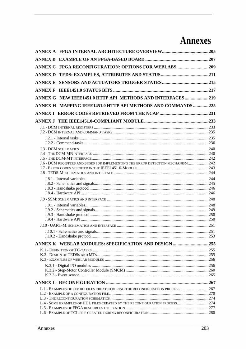
Annexes 203
Annexes ANNEX A FPGA INTERNAL ARCHITECTURE OVERVIEW ....................................... 205
ANNEX B EXAMPLE OF AN FPGA-BASED BOARD ..................................................... 207
ANNEX C FPGA RECONFIGURATION: OPTIONS FOR WEBLABS ........................... 209
ANNEX D TEDS: EXAMPLES, ATTRIBUTES AND STATUS ........................................ 211
ANNEX E SENSORS AND ACTUATORS TRIGGER STATES ....................................... 215
ANNEX F IEEE1451.0 STATUS BITS ................................................................................ 217
ANNEX G NEW IEEE1451.0 HTTP API METHODS AND INTERFACES .................... 219
ANNEX H MAPPING IEEE1451.0 HTTP API METHODS AND COMMANDS ............. 225
ANNEX I ERROR CODES RETRIEVED FROM THE NCAP ......................................... 231
ANNEX J THE IEEE1451.0-COMPLIANT MODULE ...................................................... 233
J.1 - DCM INTERNAL REGISTERS ......................................................................................................... 233 J.2 - DCM INTERNAL AND COMMAND TASKS ........................................................................................ 235
J.2.1 - Internal tasks ....................................................................................................................... 235 J.2.2 - Command-tasks .................................................................................................................. 236
J.3 - DCM SCHEMATICS ...................................................................................................................... 240 J.4 - THE DCM-MB INTERFACE .......................................................................................................... 240 J.5 - THE DCM-MT INTERFACE ........................................................................................................... 242 J.6 - DCM REGISTERS AND BUSES FOR IMPLEMENTING THE ERROR DETECTION MECHANISM ................... 242 J.7 - ERROR CODES SPECIFIED IN THE IEEE1451.0-MODULE ................................................................. 243 J.8 - TEDS-M: SCHEMATICS AND INTERFACE ....................................................................................... 244
J.8.1 - Internal variables................................................................................................................. 244 J.8.2 - Schematics and signals ........................................................................................................ 245 J.8.3 - Handshake protocol............................................................................................................. 246 J.8.4 - Hardware API ..................................................................................................................... 246
J.9 - SSM: SCHEMATICS AND INTERFACE ............................................................................................. 248
J.9.1 - Internal variables................................................................................................................. 248 J.9.2 - Schematics and signals ........................................................................................................ 249 J.9.3 - Handshake protocol............................................................................................................. 250 J.9.4 - Hardware API ..................................................................................................................... 250
J.10 - UART-M: SCHEMATICS AND INTERFACE .................................................................................... 251
J.10.1 - Schematics and signals ...................................................................................................... 251 J.10.2 - Handshake protocol ........................................................................................................... 253
ANNEX K WEBLAB MODULES: SPECIFICATION AND DESIGN .............................. 255
K.1 - DEFINITION OF TC-TASKS ........................................................................................................... 255 K.2 - DESIGN OF TEDSS AND MTS ...................................................................................................... 255 K.3 - EXAMPLES OF WEBLAB MODULES ............................................................................................... 256
K.3.1 - Digital I/O modules ........................................................................................................... 256 K.3.2 - Step-Motor Controller Module (SMCM) ............................................................................ 260 K.3.3 - Event sensor ...................................................................................................................... 265
ANNEX L RECONFIGURATION ...................................................................................... 267
L.1 - EXAMPLES OF REPORT FILES CREATED DURING THE RECONFIGURATION PROCESS .......................... 267 L.2 - EXAMPLE OF A CONFIGURATION FILE ........................................................................................... 270 L.3 - THE RECONFIGURATION SCHEMATICS .......................................................................................... 274 L.4 - SOME EXAMPLES OF HDL FILES CREATED BY THE RECONFIGURATION PROCESS............................. 274 L.5 - EXAMPLES OF FPGA RESOURCES UTILIZATION ............................................................................ 277 L.6 - EXAMPLE OF TCL FILE CREATED DURING RECONFIGURATION....................................................... 280

204 An IEEE1451.0-compliant FPGA-based reconfigurable weblab
ANNEX M VALIDATION & VERIFICATION ................................................................. 283
M.1 - SUPPORTING WEBPAGE: THE MAIN PAGE ..................................................................................... 283 M.2 - SCREENSHOTS OF VIDEOS EXEMPLIFYING THE INTERACTION WITH THE WEBLAB ........................... 284 M.3 - QUESTIONNAIRES PROVIDED FOR THE RESEARCHERS ................................................................... 285 M.4 - EXAMPLES OF WEBPAGES WITH THE PROVIDED METHODOLOGY ................................................... 289

Annex A: FPGA internal architecture overview 205
Annex A
FPGA internal architecture overview
Field Programmable Gate Arrays (FPGAs) are integrated circuits designed to be
configured. The configuration is generally specified using Hardware Description
Languages (HDLs) such as Verilog, VHDL or SystemC. FPGAs can implement any
logical function that an Application Specific Integrated Circuits (ASICs) could perform,
with the advantage to update the functionality through total or partial reconfiguration
methods (annex B provides a brief overview about these types of reconfigurations).
FPGAs contain programmable logic components called logic blocks, and an
hierarchy of reconfigurable interconnections that allow the blocks to be wired together,
somewhat like many (changeable) logic gates that can be wired in (many) different
configurations. Logic blocks can be configured to perform complex combinational
functions, or merely simple logic gates like AND and XOR. In most FPGAs, the logic
blocks also include memory elements, which may be simple flip-flops or more complete
blocks of memory. The access to the exterior is made using I/O blocks, which are also
reconfigurable. Figure A.1 presents the structural elements of an FPGA.
Figure A.1: Structural elements of an FPGA.

206 An IEEE1451.0-compliant FPGA-based reconfigurable weblab

Annex B: Example of an FPGA-based board 207
Annex B
Example of an FPGA-based board
A/D
an
d D
/A
con
ver
ters
Eth
ern
et
inte
rfac
e
bu
tto
ns
LC
D d
isp
lay
JTA
G
inte
rfac
e
Dig
ital
I/0
pin
s
PH
Y
inte
rfac
esF
PG
A
LE
Ds
ind
icat
ors
DR
AM
mem
ory
E2
PR
OM
mem
ory
bu
tto
ns
Fig
ure
B.1
: E
xam
ple
of
an
FP
GA
-base
d b
oard
fro
m X
ilin
x (
Sp
art
an
3E
).

208 An IEEE1451.0-compliant FPGA-based reconfigurable weblab

Annex C: FPGA reconfiguration: options for weblabs 209
Annex C
FPGA reconfiguration: options for weblabs
As illustrated in figure C.1, FPGA technology provides two possible solutions for
reconfiguring weblab modules, namely for swapping or for adding new modules to the
infrastructure: i) total reconfiguration or; ii) partial reconfiguration, this able to be
implemented using static or dynamic approaches.
FPGA
reconfiguration with
weblab modules
total
reconfiguration
partial
reconfiguration
static
dynamic
FPGA
FPGA
Weblab modules
New weblab module
Partial reconfiguration: only part of the FPGA is changed. Static reconfiguration stops the other modules.
Dynamic reconfiguration allows that the others modules keep running during the adding/swapping process.
Possible weblab module to swap
Possible weblab module to swap
Total reconfiguration: the entire FPGA is changed, even if only a module is added/swapped.
The FPGA stops its operation.
New weblab module
Completely redefined
Only the module is redefined
Figure C.1: Possibilities for reconfiguring an FPGA with different weblab modules.
Total reconfiguration requires reconfiguring the entire FPGA, which implies
stopping its operation whenever a new weblab module is needed. Although being the
most appropriated option when using a single FPGA for a single module, it may also be
used when a single FPGA is adopted for accommodating, at the same instant, more than
one weblab module. This option is less interesting, since it requires stopping the weblab
operation for adding or swapping the modules. Moreover, depending on the complexity
of the new modules and on the current FPGA configuration, this option typically
requires more time for the reconfiguration process when compared to the partial
reconfiguration124
. This second option should be considered when using a single FPGA
to encapsulate more than one module. It allows reconfiguring only part of the FPGA
124 M.G. Gericota et al., ‘Run-time management of logic resources on reconfigurable systems’, in
Design, Automation and Test in Europe Conference and Exhibition (DATE’2003), Munich,
Germany, 3-7 March, 2003, pp. 974–979.

210 An IEEE1451.0-compliant FPGA-based reconfigurable weblab
with one or more weblab modules, without changing the others inside. Two alternatives
are available for partial reconfiguration: a) static or b) dynamic. Static reconfiguration
requires stopping the FPGA to add/swap a module. In contrast, if dynamic
reconfiguration is adopted, an experiment my keep running even if a module is
added/swapped. Besides the high complexity of partial reconfiguration, the costs
involved are also higher than total reconfiguration, because not all FPGAs support this
option. Furthermore, adopting partial reconfiguration requires knowing the present
configuration inside the FPGA to rearrange the logic resources and to free the space for
the new module, which may create additional difficulties for implementing this option,
since it is much dependent on the tools provided by a particular manufacturer. Then,
considering the involved complexity of partial reconfiguration when compared to total
reconfiguration, suggests this last option as a valid one for every type of architecture.
Table C.1 maps the main differences between these reconfiguration options and
indicates in which architecture they should be mostly applied.
Table C.1: Options for reconfiguring FPGAs.
Total reconfiguration Partial reconfiguration
Static Dynamic
Implemented by all FPGAs Implemented in some FPGAs
The entire configuration logic
blocks are changed Only some configuration logic blocks are changed
Requires stopping the operation
(e.g. Cyclone - Altera)
Requires stopping the operation
(e.g. Spartan3- Xilinx)
Does not require stopping the
operation
(e.g. Virtex4 - Xilinx)
low FPGA prices medium FPGA prices high FPGA prices
Applied to all architectures
with one or more FPGAs and
modules, but best suggested
when a single FPGA
accommodates a single
module. The weblab will be
stopped.
Preferable when using a single FPGA to accommodate several
weblab modules. Selecting one of these configurations depends
on the reconfiguration capability of the adopted FPGA and if
the weblab can be stopped (static configuration) or should run
continuously (dynamic configuration). Typically it is too much
manufacturer dependent and hard to implement.

Annex D: TEDS: examples, attributes and status 211
Annex D
TEDS: examples, attributes and status
For exemplifying the TEDSs’ structures, table D.1 and table D.2 present two
mandatory TEDSs adopted in every compatible IEEE1451.0 device, namely the Meta-
TEDS and the TC-TEDS. Although not directly specified in these structures, every
TEDSs has associated attributes enumerated in table D.3, and particular status listed in
table D.4, both defined through two octets.
Table D.1: Meta-TEDS structure.
Field
num.
Field
name Description
Data
type
Num.
Octets
- Length UInt32 4
0-2 - reserved - -
3 TEDSID TEDS Identification Header UInt8 4
4 UUID Globally Unique Identifier UUID 10
5-9 reserved - -
Timing-related information
10 OholdOff Operational time-out Float32 4
11 SHoldOff Slow-access time-out Float32 4
12 TestTime Self-Test Time Float32 4
Number of implemented TCs
13 MaxChan Number of implemented TCs UInt16 2
14 CGroup ControlGroup information sub-block - -
Types 20, and 21 define one ControlGroup.
20 GrpType ControlGroup type UInt8 1
21 MemList ControlGroup member list UInt16
Array variable
15 VGroup VectorGroup information sub-block - -
Types 20 and 21 define one VectorGroup.
20 GrpType VectorGroup type UInt8 1
21 MemList VectorGroup member list UInt16
Array variable
16 GeoLoc Specialized VectorGroup for geographic location - -
Types 24, 20, and 21 define one set of geographic location information.
24 LocEnum Enumeration defining how location information is provided
UInt8 1
20 GrpType VectorGroup type UInt8 1
21 MemList VectorGroup member list UInt16
Array variable
17 Proxies TC proxy definition sub-block - -
Types 22, 23, and 21 define one TC proxy.
22 ChanNum TC number of the TC proxy UInt16 1
23 Organiz TC proxy data-set organization UInt8 1
21 MemList TC proxy member list UInt16
Array variable
18-19 - Reserved - -
25-127 - Reserved - -
128-
255 - Open to manufacturers - -
- Checksum UInt16 2

212 An IEEE1451.0-compliant FPGA-based reconfigurable weblab
Table D.2: TC-TEDS structure.
Field
num.
Field
name Description
Data
type
Num.
Octets
- Length UInt32 4
0-2 - reserved - -
3 TEDSID TEDS Identification Header UInt8 4
4 UUID Globally Unique Identifier UUID 10
5-9 reserved - -
TC related information
10 CalKey Calibration key UInt8 1
11 ChanType TC type key UInt8 1
12 PhyUnits Physical Units UNITS 11
50 UnitType Physical Units interpretation enumeration UInt8 1
51 Radians The exponent for Radians UInt8 1
52 SterRad The exponent for Steradians UInt8 1
53 Meters The exponent for Meters UInt8 1
54 Kilogram The exponent for Kilograms UInt8 1
55 Seconds The exponent for Seconds UInt8 1
56 Amperes The exponent for Amperes UInt8 1
57 Kelvins The exponent for Kelvins UInt8 1
58 Moles The exponent for Moles UInt8 1
59 Candelas The exponent for Candelas UInt8 1
60 UnitsExt TEDS access code for units extension UInt8 1
13 LowLimit Design operational lower range limit Float32 4
14 HiLimit Design operational upper range limit Float32 4
15 OError Worst-case uncertainty Float32 4
16 SelfTest Self-test key UInt8 1
17 MRange Multi-range capability UInt8 1 Data converter-related information
18 Sample - -
40 DatModel Data model UInt8 1
41 ModLenth Data model length UInt8 1
42 SigBits Model significant bits UInt16 2
10 DataSet - -
43 Repeats Maximum data repetitions UInt16 2
44 SOrigin Series origin Float32 4
45 StepSize Series increment Float32 4
46 SUnits Series units UNITS 11
47 PreTrigg Maximum pre-trigger samples UInt16 2 Timing-related information
20 UpdateT TC update time (tu) Float32 4
21 WSetupT TC write setup time (tws) Float32 4
22 RSetupT TC read setup time (trs) Float32 4 Float32 4
23 SPeriod TC sampling period (tsp) Float32 4
24 WarmUpT TC warm-up time Float32 4
25 RDelayT TC read delay time (tch) Float32 4
26 TestTime TC self-test time requirement Float32 4 Time of the sample information
27 TimeSrc Source for the time of sample UInt8 1
28 InPropDl Incoming propagation delay through the data transport logic Float32 4
29 OutPropD Outgoing propagation delay through the data transport logic Float32 4
30 TSError Trigger-to-sample delay uncertainty Float32 4 Attributes
31 Sampling Sampling attribute - -
48 SampMode Sampling mode capability UInt8 1
49 SDefault Default sampling mode UInt8 1
32 DataXmit Data transmission attribute UInt8 1
33 Buffered Buffered attribute UInt8 1

Annex D: TEDS: examples, attributes and status 213
34 EndOfSet End-of-data-set operation attribute UInt8 1
35 EdgeRpt Edge-to-report attribute UInt8 1
36 ActHalt Actuator-halt attribute UInt8 1 Sensitivity
37 Directon Sensitivity direction Float32 4
38 DAngles Direction angles 2 Float32 8 Options
ESOption Event sensor options UInt8 1
61–127 - Reserved - - 128–255
- Open to manufacturers - -
- Checksum UInt16 2
Table D.3: TEDS’ attributes implemented in an octet.
Bit Data type Field name Definition
0 Boolean TEDSAttrib.ReadOnly Read-only - Set to true if TEDS may be read but notwritten.
1 Boolean TEDSAttrib.NotAvail Unsupported - Set to true if TEDS is not supported by
a TC.
2 Boolean TEDSAttrib.Invalid Invalid - Set to true if the current TEDS image is
invalid.
3 Boolean TEDSAttrib.Virtual Virtual TEDS - This bit is set to true if this is a virtual
TEDS (not stored in the TIM).
4 Boolean TEDSAttrib.TextTEDS Text TEDS - Set to true if the TEDS is text based.
5 Boolean TEDSAttrib.Adaptive
Adaptive - Set to true if the contents of the TEDS can
be changed by the TIM or TC without the NCAP
issuing a WriteTEDSsegment command.
6 Boolean TEDSAttrib.MfgrDefine
MfgrDefine - Set to True if the contents of this TEDS
are defined by the manufacturer and will only conform
to the structures defined in the standard if the TextTEDS attribute is also set.
7 Boolean TEDSAttrib.Reserved Reserved.
Table D.4: TEDS’ status implemented in an octet.
Bit Data type Field name Definition
0 Boolean TEDSStatus.TooLarge Too Large - The last TEDS image received was too
large to fit in the memory allocated to this TEDS.
1-3 Boolean TEDSStatus.Reserved Reserved.
4-7 Boolean TEDSStatus.Open Open to manufacturers.

214 An IEEE1451.0-compliant FPGA-based reconfigurable weblab

Annex E: Sensors and actuators trigger states 215
Annex E
Sensors and actuators trigger states
The transitions on the operating states follow two trigger state diagrams represented
in figure E.1, for sensors, and in figure E.2, for actuators. Each state represents the
transducer operating state that changes according to the defined operation mode.
Information concerning these diagrams is provided in figure E.3.
Trigger
initialize
Trigger
operating
Pré-
triggerWait for
trigger
Free
running
Wait for
read
Sampling
TC trigger
enabled
[sampling mode]
Free running
with pré-trigger
[sampling mode]
Wait for trigger
[sampling mode]
Free running with/
without pré-trigger
or continous
[sampling mode]
Immediate
Sampling and
discarding
*done
Sampling
into data-set
Sampling
into data-set
[read TC data set segment]
*trigger
*trigger
*trigger or
[read TC data
set segment]
POWER ON
*exit or
TC trigger disabled
Figure E.1: Sensor trigger states.
Trigger
initialize
Trigger
operating
Transverse
data set
Wait for
triggerFree
running
Wait for
write
Halt
mode
TC trigger
enabled
[sampling mode]
Wait for trigger
[sampling mode]
Free running without
pré-trigger or
continous
[sampling mode]
Immediate
Old data set
output
[write TC data set segment]
*trigger
*trigger
POWER ONNot in transverse data set state & not in
actuator halt mode state & *exit
*exit
*done
Figure E.2: Actuator trigger states.

216 An IEEE1451.0-compliant FPGA-based reconfigurable weblab
*trigger if one of the following occur:
1. received the trigger command;
2. events within the TIM.
*exit if one of the following occur:
1. received [reset] or [device clear] or [abort trigger] or [write TC trigger state] = disabled;
2. TIM no longer in TIM active state;
3. transducer no longer in transducer operating state.
*done
[actuator] if the TC has transversed to the end of all DSs (all buffers) and the End of DS
operation is set to hold.
[sensor]if not in continous sampling mode and one of the bellow occur:
1. TC done with repetitive count (fills-in DSs and buffers if appropriate)
2. event sensor got the enabled event (rising, falling, both).
Notes:
[name] indicates a command.
name state indicates a state.
Figure E.3: Information notes for the trigger state diagrams.

Annex F: IEEE1451.0 status bits 217
Annex F
IEEE1451.0 status bits
To monitor internal operations, namely if a specific command was correctly applied,
if there was a change in a TEDS, etc., the IEEE1451.0 implements status registers with
32 bits (condition, event and mask registers) for each TC and another for the TIM. As
represented in table F.1, most of the registers have the same bits for the TIM and for all
TCs (excluding the mask register that does not use bit 0). The TCs and the TIM can
associate the same registers according to an OR logic, which means that if a bit on a TC
status register is set, the correspondent bit on the TIM may also be set (if they are used
for the same purpose).
Table F.1: Status bits defined by the IEEE1451.0 Std.
Bit Status bits
TIM TC
0 Service request Service request
1 TEDS changed TEDS changed
2 Invalid command Reserved (implemented as an invalid command)
3 Command rejected Command rejected
4 Missed data or event Missed data or event
5 Data/event Data/event
6 Hardware error Hardware error
7 Not operational Not operational
8 Protocol error Reserved
9 Data available / processed Data available / processed
10 Busy Busy
11 Failed calibration Failed calibration
12 Failed self-test Failed self-test
13 Data over/under range Data over/under range
14 Corrections disabled Corrections disabled
15 Consumables exhausted Consumables exhausted
16 Reserved Not-the-first-read-of-this-data-set
17-23 Reserved Reserved
24-31 Open to manufactures Open to manufactures

218 An IEEE1451.0-compliant FPGA-based reconfigurable weblab

Annex G: New IEEE1451.0 HTTP API methods and interfaces 219
Annex G
New IEEE1451.0 HTTP API
methods and interfaces
This annex presents the extensions proposed to the IEEE1451.0-HTTP API for
implementing the architecture specified in section 4.6. The interfaces and methods are
much similar to the ones already specified in the IEEE1451.0 Std. The following tables
detail the arguments of each corresponding method.
Table G.1: NCAPRegister method.
Name: NCAPRegister
Path: http://<LabServer IP address>:<port>/NCAPRegister?register=<value>&
IPadd=<value>& portNum=<value>&responseFormat=<value>
Parameters:
Input
_Boolean register: Specifies if it is a register (=1) or unregister operation (=0).
UInt32 IPadd: IP addresses of the registered/unregistered NCAP in the Weblab server.
UInt16 portNum: Port number of the registered/unregistered NCAP in the Weblab
server.
_String responseFormat (values: “text”, ”HTML” or “xml” )
(response format retrieved as indicated in section 12.1.2 of the IEEE1451.0 Std.).
output
UInt16 errorCode: error information (described in chapter 9 of the IEEE1451.0 Std.).
UInt32 IPadd: IP addresses of the registered/unregistered NCAP in the weblab server
(returns null if registration / unregistration was not correctly applied).
UInt16 portNum: Port number of the registered/nregistered NCAP in the weblab
server (returns null if registration /unregistration was not correctly applied).
output formats
All response formats should be in accordance with the IEEE1451.0 Std. as described
in its section 12.1.2.
For XML format it shall use the following schema: <?xml version="1.0" encoding="UTF-8"?>
<xs:schema xmlns:xs="http://www.w3.org/2001/XMLSchema"
xmlns:stml=http://grouper.ieee.org/groups/1451/0/1451HTTPAPI
<xs:complexType name="NCAPRegisterHTTPResponse">
<xs:sequence>
<xs:element name="errorCode" type="stml:UInt16"/>
<xs:element name="IPadd" type="stml:UInt32"/>
<xs:element name="portNum" type="stml:UInt16"/>
</xs:sequence>
</xs:complexType>
</xs:schema>

220 An IEEE1451.0-compliant FPGA-based reconfigurable weblab
Table G.2: NCAPDiscovery method.
Name: NCAPDiscovery
Path: http://<LabServer IP address>:<port>/NCAPDiscovery?responseFormat=<value>
Parameters:
Input
_String responseFormat (values: “text”, ”HTML” or “xml” )
(response format retrieved as indicated in section 12.1.2 of the IEEE1451.0 Std.).
output
UInt16 errorCode: error information (described in chapter 9 of the IEEE1451.0 Std.).
UInt32Array IPadd: IP addresses of all registered NCAP in the weblab server.
UInt16Array portNum: Port number of all registered NCAP in the weblab server.
output formats
All response formats should be in accordance with the IEEE1451.0 Std. as described
in its section 12.1.2.
For XML format it shall use the following schema: <?xml version="1.0" encoding="UTF-8"?>
<xs:schema xmlns:xs="http://www.w3.org/2001/XMLSchema"
xmlns:stml=http://grouper.ieee.org/groups/1451/0/1451HTTPAPI
<xs:complexType name="NCAPDiscoveryHTTPResponse">
<xs:sequence>
<xs:element name="errorCode" type="stml:UInt16"/>
<xs:element name="IPadd" type="stml:UInt32Array"/>
<xs:element name="portNum" type="stml:UInt16Array"/>
</xs:sequence>
</xs:complexType>
</xs:schema>
Table G.3: ReadLabTEDS method.
Name: ReadLabTEDS
Path: http://<NCAP IPadd >:<NCAP portNum >/ ReadLabTeds?
responseFormat=<value>&field=<value>
Parameters:
Input
__String responseFormat (values: “text”, ”HTML” or “xml” )
(response format retrieved as indicated in section 12.1.2 of the IEEE1451.0 Std.).
Uint8 field (values: 0 to 255 or null).
Specify the field to read (0 to 255) or the entire LabTEDS is no field is specified (null).
output
UInt16 errorCode: error information (described in chapter 9 of the IEEE1451.0 Std.).
UInt32 IPadd: IP address of the specified NCAP.
UInt16 portNum: Port number of the specified NCAP.
ArgumentArray teds: array containing data read from the specified LabTEDS.
output formats
All response formats should be in accordance with the IEEE1451.0 Std. as described
in its section 12.1.2.
For XML format it shall use the following schema: <?xml version="1.0" encoding="UTF-8"?>
<xs:schema xmlns:xs="http://www.w3.org/2001/XMLSchema"
xmlns:stml=http://grouper.ieee.org/groups/1451/0/1451HTTPAPI
<xs:complexType name="ReadLabTedsHTTPResponse">
<xs:sequence>
<xs:element name="errorCode" type="stml:UInt16"/>
<xs:element name="IPadd"type="stml:UInt32Array"/>
<xs:element name="portNum" type="stml:UInt16Array"/>
<xs:element name="teds" type="stml:ArgumentArrayType"/>
</xs:sequence>
</xs:complexType>
</xs:schema>

Annex G: New IEEE1451.0 HTTP API methods and interfaces 221
Table G.4: WriteLabTEDS method.
Name: WriteLabTEDS
Path: http://<NCAP IPadd >:<NCAP portNum >/ WriteLabTeds?
responseFormat=<value>&field=<value>&teds=<value>
Parameters:
Input
__String responseFormat (values: “text”, ”HTML” or “xml” )
(response format retrieved as indicated in section 12.1.2 of the IEEE1451.0 Std.).
Uint8 field (values: 0 to 255 or null). Specify the field to write (0 to 255) or null to specify the entire LabTEDS.
ArgumentArray teds: array containing data to write into the LabTEDS
(user must guarantee that all other LabTEDSs fields are coherent).
output
UInt16 errorCode: error information (described in chapter 9 of the IEEE1451.0 Std.).
UInt32 IPadd: IP address of the specified NCAP.
UInt16 portNum: Port number of the specified NCAP.
output formats
All response formats should be in accordance with the IEEE1451.0 Std. as described
in its section 12.1.2.
For XML format it shall use the following schema <?xml version="1.0" encoding="UTF-8"?>
<xs:schema xmlns:xs="http://www.w3.org/2001/XMLSchema"
xmlns:stml=http://grouper.ieee.org/groups/1451/0/1451HTTPAPI
<xs:complexType name="WriteLabTedsHTTPResponse">
<xs:sequence>
<xs:element name="errorCode" type="stml:UInt16"/>
<xs:element name="IPadd"type="stml:UInt32Array"/>
<xs:element name="portNum" type="stml:UInt16Array"/>
</xs:sequence>
</xs:complexType>
</xs:schema>
Table G.5: ReadTIM method.
Name: ReadTIM
Path: http://< NCAP IPadd >:< NCAP
portNum>/ReadTIM?timid=<value>&timeout=<value>&responseFormat<value>
Parameters:
Input
UInt16 timId.
TimeDuration timeout.
_String responseFormat (values: “text”, ”HTML” or “xml” )
(response format retrieved as indicated in section 12.1.2 of the IEEE1451.0 Std.).
output
UInt16 errorCode: error information (described in chapter 9 of the IEEE1451.0 Std.).
UInt16 timId.
ArgumentArray TimData.
output formats
All response formats should be in accordance with the IEEE1451.0 Std. as described
in its section 12.1.2.
For XML format it shall use the following schema: <?xml version="1.0" encoding="UTF-8"?>
<xs:schema xmlns:xs="http://www.w3.org/2001/XMLSchema"
xmlns:stml=http://grouper.ieee.org/groups/1451/0/1451HTTPAPI
<xs:complexType name=" ReadTIMHTTPResponse">
<xs:sequence>
<xs:element name="errorCode" type="stml:UInt16"/>
<xs:element name=" timId " type="stml: UInt16"/>
<xs:element name="TimData " type="stml: ArgumentArray"/>
</xs:sequence>
</xs:complexType>
</xs:schema>

222 An IEEE1451.0-compliant FPGA-based reconfigurable weblab
Table G.6: WriteTIM method.
Name: WriteTIM
Path: http://< NCAP IPadd >:< NCAP portNum >/WriteTIM?
timId=<value>&timeout=<value>&TimData=<value>&responseFormat=<value>
Parameters:
Input
UInt16 timId.
TimeDuration timeout.
ArgumentArray TimData.
_String responseFormat (values: “text”, ”HTML” or “xml” )
(response format retrieved as indicated in section 12.1.2 of the IEEE1451.0 Std.).
output
UInt16 errorCode: error information (described in chapter 9 of the IEEE1451.0 Std.).
UInt16 timId.
output formats
All response formats should be in accordance with the IEEE1451.0 Std. as described in its section 12.1.2.
For XML format it shall use the following schema: <?xml version="1.0" encoding="UTF-8"?>
<xs:schema xmlns:xs="http://www.w3.org/2001/XMLSchema"
xmlns:stml=http://grouper.ieee.org/groups/1451/0/1451HTTPAPI
<xs:complexType name=" WriteTIMHTTPResponse">
<xs:sequence>
<xs:element name="errorCode" type="stml:UInt16"/>
<xs:element name=" timId " type="stml: UInt16 "/>
</xs:sequence>
</xs:complexType>
</xs:schema>
Table G.7: ReadLog method.
Name: ReadLog
Path: http://< NCAP IPadd >:< NCAP portNum
>/ReadLog?Timeout=<value>&responseFormat=<value>
Parameters:
Input
TimeDuration timeout.
_String responseFormat (values: “text”, ”HTML” or “xml” )
(response format retrieved as indicated in section 12.1.2 of the IEEE1451.0 Std.).
output
UInt16 errorCode: error information (described in chapter 9 of the IEEE1451.0 Std.).
ArgumentArray logData.
output formats
All response formats should be in accordance with the IEEE1451.0 Std. as described
in section its 12.1.2.
For XML format it shall use the following schema: <?xml version="1.0" encoding="UTF-8"?>
<xs:schema xmlns:xs="http://www.w3.org/2001/XMLSchema"
xmlns:stml=http://grouper.ieee.org/groups/1451/0/1451HTTPAPI
<xs:complexType name=" ReadLogHTTPResponse">
<xs:sequence>
<xs:element name="errorCode" type="stml:UInt16"/>
<xs:element name=" logData " type="stml: ArgumentArray "/>
</xs:sequence>
</xs:complexType>
</xs:schema>
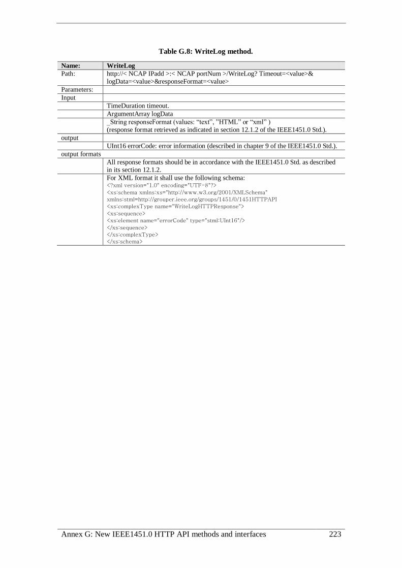
Annex G: New IEEE1451.0 HTTP API methods and interfaces 223
Table G.8: WriteLog method.
Name: WriteLog
Path: http://< NCAP IPadd >:< NCAP portNum >/WriteLog? Timeout=<value>&
logData=<value>&responseFormat=<value>
Parameters:
Input
TimeDuration timeout.
ArgumentArray logData
_String responseFormat (values: “text”, ”HTML” or “xml” )
(response format retrieved as indicated in section 12.1.2 of the IEEE1451.0 Std.).
output
UInt16 errorCode: error information (described in chapter 9 of the IEEE1451.0 Std.).
output formats
All response formats should be in accordance with the IEEE1451.0 Std. as described in its section 12.1.2.
For XML format it shall use the following schema: <?xml version="1.0" encoding="UTF-8"?>
<xs:schema xmlns:xs="http://www.w3.org/2001/XMLSchema"
xmlns:stml=http://grouper.ieee.org/groups/1451/0/1451HTTPAPI
<xs:complexType name="WriteLogHTTPResponse">
<xs:sequence>
<xs:element name="errorCode" type="stml:UInt16"/>
</xs:sequence>
</xs:complexType>
</xs:schema>

224 An IEEE1451.0-compliant FPGA-based reconfigurable weblab

Annex H: Mapping IEEE1451.0 HTTP API methods and commands 225
Annex H
Mapping IEEE1451.0 HTTP API
methods and commands
The following tables specify the mapping between the IEEE1451.0 HTTP API
methods and the commands described in the IEEE1451.0 Std. For analysing these
tables, readers should be familiar with the IEEE1451.0 Std. since not all information is
detailed. New methods are not mapped because they do not interact with the commands.
It is also important to stress that this is an alternative solution for implementing weblab
infrastructures based on the IEEE1451.0 Std., in particular for solutions that use a single
NCAP-TIM connection.
Table H.1: Mapping the ReadData method to SamplingMode and ReadTCDSsegment
commands.
Tra
nsd
uce
r A
cces
s
AP
I
Name: ReadData (section 12.3.1.1 of the IEEE1451.0 Std.)
Path: http://<NCAP IPadd >:<NCAP portNum>/1451/TransducerAccess/ReadData
Input parameters:
UInt16 timId UInt16 channelId
TimeDuration timeout
UInt8 SamplingMode
_String responseFormat
Output parameters:
UInt16 errorCode UInt16 timId
UInt16 channelId
ArgumentArray transducerData
Co
mm
and
s
Name: SamplingMode (section 7.1.2.4 of the IEEE1451.0 Std.)
Input parameters:
UInt8 SamplingMode
Output parameters:
No reply
Name: ReadTCDSsegment (section 7.1.3.1 of the IEEE1451.0 Std.)
Input parameters:
UInt32 DataSetOffset
Output parameters:
UInt32 DataSetOffset
2 N*UInt8 DataBlock
Comments: Using the ReadData starts a blocking operation and requires the use of two commands:
the SamplingMode to define the samplingMode, followed by the ReadTCDSsegment to read one or
more data blocks depending on the available data. The DataSetOffset input parameter of the
ReadTCDSsegment command should always start at 0 and should be applied until all data were
returned. The ArgumentArray output parameter of the ReadData should be completed with all
returned data blocks of the ReadTCDSsegment command.
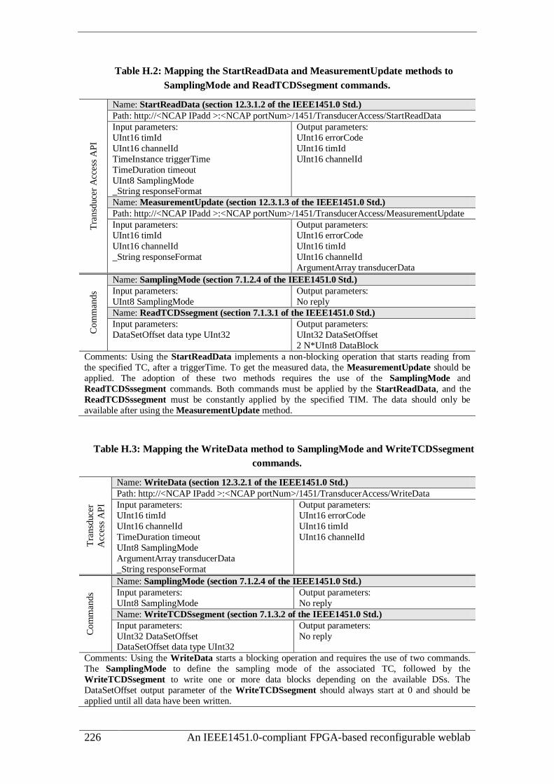
226 An IEEE1451.0-compliant FPGA-based reconfigurable weblab
Table H.2: Mapping the StartReadData and MeasurementUpdate methods to
SamplingMode and ReadTCDSsegment commands. T
ransd
uce
r A
cces
s A
PI
Name: StartReadData (section 12.3.1.2 of the IEEE1451.0 Std.)
Path: http://<NCAP IPadd >:<NCAP portNum>/1451/TransducerAccess/StartReadData
Input parameters:
UInt16 timId
UInt16 channelId
TimeInstance triggerTime
TimeDuration timeout
UInt8 SamplingMode _String responseFormat
Output parameters:
UInt16 errorCode
UInt16 timId
UInt16 channelId
Name: MeasurementUpdate (section 12.3.1.3 of the IEEE1451.0 Std.)
Path: http://<NCAP IPadd >:<NCAP portNum>/1451/TransducerAccess/MeasurementUpdate
Input parameters:
UInt16 timId
UInt16 channelId
_String responseFormat
Output parameters:
UInt16 errorCode
UInt16 timId
UInt16 channelId
ArgumentArray transducerData
Co
mm
ands
Name: SamplingMode (section 7.1.2.4 of the IEEE1451.0 Std.)
Input parameters:
UInt8 SamplingMode
Output parameters:
No reply
Name: ReadTCDSsegment (section 7.1.3.1 of the IEEE1451.0 Std.)
Input parameters:
DataSetOffset data type UInt32
Output parameters:
UInt32 DataSetOffset
2 N*UInt8 DataBlock
Comments: Using the StartReadData implements a non-blocking operation that starts reading from
the specified TC, after a triggerTime. To get the measured data, the MeasurementUpdate should be
applied. The adoption of these two methods requires the use of the SamplingMode and
ReadTCDSssegment commands. Both commands must be applied by the StartReadData, and the
ReadTCDSssegment must be constantly applied by the specified TIM. The data should only be
available after using the MeasurementUpdate method.
Table H.3: Mapping the WriteData method to SamplingMode and WriteTCDSsegment
commands.
Tra
nsd
uce
r
Acc
ess
AP
I
Name: WriteData (section 12.3.2.1 of the IEEE1451.0 Std.)
Path: http://<NCAP IPadd >:<NCAP portNum>/1451/TransducerAccess/WriteData
Input parameters:
UInt16 timId
UInt16 channelId
TimeDuration timeout
UInt8 SamplingMode
ArgumentArray transducerData
_String responseFormat
Output parameters:
UInt16 errorCode
UInt16 timId
UInt16 channelId
Com
man
ds
Name: SamplingMode (section 7.1.2.4 of the IEEE1451.0 Std.)
Input parameters:
UInt8 SamplingMode
Output parameters:
No reply
Name: WriteTCDSsegment (section 7.1.3.2 of the IEEE1451.0 Std.)
Input parameters:
UInt32 DataSetOffset DataSetOffset data type UInt32
Output parameters:
No reply
Comments: Using the WriteData starts a blocking operation and requires the use of two commands.
The SamplingMode to define the sampling mode of the associated TC, followed by the
WriteTCDSsegment to write one or more data blocks depending on the available DSs. The
DataSetOffset output parameter of the WriteTCDSsegment should always start at 0 and should be
applied until all data have been written.

Annex H: Mapping IEEE1451.0 HTTP API methods and commands 227
Table H.4: Mapping the StartWriteData method to SamplingMode and WriteTCDSs
commands. T
ransd
uce
r A
cces
s A
PI
Name: StartWriteData (section 12.3.2.2 of the IEEE1451.0 Std.)
Path: http://<NCAP IPadd >:<NCAP portNum>/1451/TransducerAccess/StartWriteData
Input parameters:
UInt16 timId
UInt16 channelId
TimeInstance triggerTime
TimeDuration timeout
UInt8 SamplingMode ArgumentArray transducerData
_String responseFormat
Output parameters:
UInt16 errorCode
UInt16 timId
UInt16 channelId
Com
man
ds
Name: SamplingMode (section 7.1.2.4 of the IEEE1451.0 Std.)
Input parameters: UInt8 SamplingMode
Output parameters: No reply
Name: WriteTCDSsegment (section 7.1.3.2 of the IEEE1451.0 Std.)
Input parameters:
UInt32 DataSetOffset
DataSetOffset data type UInt32
Output parameters:
No reply
Comments: Using the StartWriteData implements a non-blocking operation that starts writing in the
specified TC, after a triggerTime. Requires the use of the SamplingMode and WriteTCDSsegment
commands. As described in the standard, the user is responsible for determining when the command
completes its action by sending the SendCommand method (section 12.5.1 of the IEEE1451.0 Std.)
with the ReadStatusEventRegister command (section 7.1.1.8 of the IEEE1451.0 Std.), and checking
for the DataProcessed bit (section 5.13.10 of the IEEE1451.0 Std.) to be asserted in the event register
of the specified TIM ID and TC ID.
Table H.5: Mapping the ReadTEDS and ReadRawTEDS methods to the
ReadTEDSsegment command.
TE
DS
Man
ager
AP
I
Name: ReadTEDS (section 12.4.1 of the IEEE1451.0 Std.) and ReadRawTEDS (section
12.4.2 of the IEEE1451.0 Std.)
Path: http://<NCAP IPadd >:<NCAP portNum>/1451/TedsManager/ReadTeds
Path: http://<NCAP IPadd >:<NCAP portNum>/1451/TedsManager/ReadRawTeds
Input parameters:
UInt16 timId
UInt16 channelId
TimeDuration timeout
UInt8 TedsType
_String responseFormat
Output parameters:
UInt16 errorCode
UInt16 timId
UInt16 channelId
UInt8 TedsType
ArgumentArray Teds
Com
man
ds Name: ReadTEDSsegment (section 7.1.1.2 of the IEEE1451.0 Std.)
Input parameters:
UInt8 TEDSAccessCode
UInt32 TEDSOffset
Output parameters:
UInt32 TEDSOffset
OctetArray RawTEDSBlock
Comments: Both methods read TEDSs and the ReadTEDSsegment command should be used if the
TEDSs are located in the TIM. If the ReadTEDS method is applied and the accessed TEDSs are
cached in NCAP, the ReadTEDSsegment command is not used. Otherwise, if the ReadRawTEDS
method is applied or if the ReadTEDS method is applied to a TEDS only located in the TIM, the
ReadTEDSsegment command should be always used. The NCAP is the responsible for specifying the
TEDSOffset parameter until all data have been read.

228 An IEEE1451.0-compliant FPGA-based reconfigurable weblab
Table H.6: Mapping the UpdateTEDSCache to the ReadTEDSsegment command.
TE
DS
Man
ager
AP
I Name: UpdateTEDSCache (section 12.4.5 of the IEEE1451.0 Std.)
Path: http://<NCAP IPadd >:<NCAP portNum>/1451/TedsManager/UpdateTedsCache
Input parameters:
UInt16 timId
UInt16 channelId TimeDuration timeout
UInt8 TedsType
_String responseFormat
Output parameters:
UInt16 errorCode
UInt16 timId UInt16 channelId
UInt8 tedsType
Com
man
ds Name: ReadTEDSsegment (section 7.1.1.2 of the IEEE1451.0 Std.)
Input parameters:
UInt8 TEDSAccessCode
UInt32 TEDSOffset
OctetArray RawTEDSBlock
Output parameters:
No reply
Comments: The use of the UpdateTEDSCache method can only be applied if there is a cached TEDS
in NCAP, otherwise it does not make sense its adoption. If there is a cached TEDS, the
ReadTEDSsegment command is applied to retrieve all data from a specific TEDS and the checksum
will be compared to the checksum of the cached TEDS. If both checksums differ, the cached TEDS
should be updated with the values read from the TEDS retrieved from the TIM.
Table H.7: Mapping the WriteTEDS and WriteRawTEDS methods to the
WriteTEDSsegment command.
TE
DS
Man
ager
AP
I
Name: WriteTEDS (section 12.4.3 of the IEEE1451.0 Std.) and WriteRawTEDS (section
12.4.4 of the IEEE1451.0 Std.)
Path: http://<NCAP IPadd >:<NCAP portNum>/1451/TedsManager/WriteTeds
Path: http://<NCAP IPadd >:<NCAP portNum>/1451/TedsManager/WriteRawTeds
Input parameters:
UInt16 timId
UInt16 channelId
TimeDuration timeout
UInt8 TedsType
ArgumentArray Teds
_String responseFormat
Output parameters:
UInt16 errorCode
UInt16 timId
UInt16 channelId
UInt8 tedsType
Co
mm
and
s Name: WriteTEDSsegment (section 7.1.1.3 of the IEEE1451.0 Std.)
Input parameters:
UInt8 TEDSAccessCode
UInt32 TEDSOffset
OctetArray RawTEDSBlock
Output parameters:
No reply
Comments: Both methods allow writing data into a TEDS and should use the WriteTEDSsegment
command if a TEDS is located in the TIM. If the WriteTEDS method is applied, and the accessed TEDS is only available in the NCAP, the WriteTEDSsegment command is not used. Otherwise, if the
WriteTEDS is applied to the TEDS only located in the TIM, or if it is applied the WriteRawTEDS
method, which obliges bypassing any available cached TEDSs, the WriteTEDSsegment command
should be always used. If the TEDS is not cached in the NCAP, the use of the WriteTEDS will create
one. The NCAP processor should be the responsible for specifying the TEDSOffset parameter until all
data have been written.

Annex H: Mapping IEEE1451.0 HTTP API methods and commands 229
Table H.8: Mapping the SendCommand method. T
ransd
uce
r M
anag
er A
PI Name: SendCommand (section 12.5.1 of the IEEE1451.0 Std.)
Path: http://<NCAP IPadd >:<NCAP portNum>/1451/TransducerManager/SendCommand
Input parameters:
UInt16 timId
UInt16 channelId TimeDuration timeout
UInt8 cmdClassId
UInt8 cmdFunctionId
ArgumentArray inArgs
_String responseFormat
Output parameters:
UInt16 errorCode
UInt16 timId UInt16 channelId
ArgumentArray outArgs
Comments: This method performs a blocking operation and should be directly mapped to any
IEEE1451.0 Std. command.
Table H.9: Mapping the StartCommand and CommandComplete methods.
Tra
nsd
uce
r M
anag
er A
PI
Name: StartCommand (section 12.5.2 of the IEEE1451.0 Std.)
Path: http://<NCAP IPadd >:<NCAP portNum>/1451/TransducerManager/StartCommand
Input parameters:
UInt16 timId
UInt16 channelId
TimeInstance triggerTime
TimeDuration timeout
UInt8 cmdClassId
UInt8 cmdFunctionId
ArgumentArray inArgs
_String responseFormat
Output parameters:
UInt16 errorCode
UInt16 timId
UInt16 channelId
Name: CommandComplete (section 12.5.3 of the IEEE1451.0 Std.)
Path: http://<NCAP IPadd >:<NCAP portNum>/1451/TransducerManager/CommandComplete
Input parameters:
UInt16 timId UInt16 channelId
_String responseFormat
Output parameters:
UInt16 errorCode UInt16 timId
UInt16 channelId
ArgumentArray outArgs
Comments: These methods perform a non-blocking operation and should be directly mapped to any
IEEE1451.0 Std. command. The CommandComplete completes a non-blocking operation initiated by
the StartCommand, retrieving the results obtained by this last method. This management should be
made by the NCAP.
Table H.10: Mapping the Trigger and the StartTrigger methods to commands
ReadTEDSsegment, SamplingMode and TriggerCommand.
Tra
nsd
uce
r M
anag
er A
PI
Name: Trigger (section 12.5.4 of the IEEE1451.0 Std.) and StartTrigger (section 12.5.5 of
the IEEE1451.0 Std.)
Path: http://<NCAP IPadd >:<NCAP portNum>/1451/TransducerManager/Trigger
Path: http://<NCAP IPadd >:<NCAP portNum>/1451/TransducerManager/StartTrigger
Input parameters:
UInt16 timId
UInt16 channelId
TimeInstance triggerTime
TimeDuration timeout
Uint16 SamplingMode
_String responseFormat
Output parameters:
UInt16 errorCode
UInt16 timId
UInt16 channelId

230 An IEEE1451.0-compliant FPGA-based reconfigurable weblab
Com
man
ds
Name: ReadTEDSsegment (section 7.1.1.2 of the IEEE1451.0 Std.)
Input parameters:
UInt8 TEDSAccessCode UInt32 TEDSOffset
OctetArray RawTEDSBlock
Output parameters:
No reply
Name: SamplingMode (section 7.1.2.4 of the IEEE1451.0 Std.)
Input parameters:
UInt8 SamplingMode
Output parameters:
No reply
Name: TriggerCommand (section 7.1.3.3 of the IEEE1451.0 Std.)
Input parameters:
No arguments
Output parameters:
No reply
Comments: The Trigger method performs a blocking trigger and is directly mapped to the Trigger
command. However, the input parameter named SamplingMode should indicate the TC operation
mode. Before sending this Trigger command to the TIM, the available sampling modes should be read
from field 31 of TC-TEDS using the ReadTEDSsegment command and compared with the
SamplingMode parameter to evaluate if it is a valid mode for the specified TC. If valid, the
SamplingMode command with the Trigger command should be applied. Otherwise, an error should
be provided through the errorCode parameter. The StartTrigger method is similar to the Trigger
method but it performs a non-blocking trigger. The user is responsible for determining if the Trigger
command was completed by sending the ReadStatusEventRegister command through the SendCommand method, to evaluate the DataProcessed bit (section 5.13.1.10 of the IEEE1451.0 Std.).

Annex I: Error codes retrieved from the NCAP 231
Annex I
Error codes retrieved from the NCAP
The error codes retrieved from the NCAP are defined according to the code structure
defined in the IEEE1451.0 Std. that uses a word with 16 bits wide, mapped according to
the event registers within the TIM. Most of the codes are not implemented since the
current infrastructure was designed according to a thin implementation of the
IEEE1451.0 Std., which does not use the middle layers of the NCAP-TIM reference
model, namely the Transducer services interface and the Module communication APIs.
The implemented codes are defined in two parts: i) error source, defined in the most
significative 3 bits (table I.1) and; ii) an error enumeration, encoded in the least
significative 13 bits (table I.2).
Table I.1: Error source codes.
Error source [bits 15-13]
0 000 NCAP error (Error from the local IEEE1451.0 layer)
1 001 - not used - (Error from the local IEEE1451.X layer)
2 010 - not used - (Error from the remote IEEE1451.X layer)
3 011 TIM error (Error from the remote IEEE1451.0 layer)
4 100 - not used - (Error from the remote application layer)
5 101 - not used - (Reserved)
6 110 - not used - (Reserved)
7 111 - not used - (Reserved)
Table I.2: Error enumeration codes.
Error enumeration [bits 12-0]
0 0.0000.0000.0000 No error (NO_ERROR - No error, operation successful)
1 0.0000.0000.0001 Invalid command ID (INVALID_COMMID - Invalid command ID)
2 0.0000.0000.0010 Unknown destination TC/TIM ID (UNKNOWN_DESTID - unknown
destination ID)
3 0.0000.0000.0011 Time out (TIMEOUT - Operation time-out )
4 0.0000.0000.0100 - not used - (NETWORK_FAILURE - Destination unreachable)
5 0.0000.0000.0101 - not used - (NETWORK_CORRUPTION - Corrupt communication)
6 0.0000.0000.0110 Memory error (MEMORY - Local out-of-memory error)
7 0.0000.0000.0111 - not used - (QOS_FAILURE - Network QoS violation)
8 0.0000.0000.1000 - not used - (MCAST_NOT_SUPPORTED - Multicast not supported or
operation invalid for multicast)
9 0.0000.0000.1001 - not used - (UNKNOWN_GROUPID - Unknown group ID)
10 0.0000.0000.1010 - not used - (UNKNOWN_MODULEID - Unknown module ID)
11 0.0000.0000.1011 - not used - (UNKNOWN_MSGID - Unknown msg ID)
12 0.0000.0000.1100 - not used - (NOT_GROUP_MEMBER - Dest. ID not in the group)
13 0.0000.0000.1101 - not used - (ILLEGAL_MODE - The mode parameter is not valid)
14 0.0000.0000.1110 - not used - (LOCKED_RESOURCE - Resource accessed is locked)
15 0.0000.0000.1111 Fatal TEDS error (FATAL_TEDS_ERROR - An error in the TEDS
makes the device unusable)
16 0.0000.0001.0000 Non fatal TEDS error (NON-FATAL_TEDS_ERROR - The value in a
field in the TEDS is unusable, but the device will still work)

232 An IEEE1451.0-compliant FPGA-based reconfigurable weblab
17 0.0000.0001.0001 - not used - (CLOSE_ON_LOCKED_RESOURCE - A warning error code
returned to signal that a close on a locked resource was performed)
18 0.0000.0001.0010
- not used - (LOCK_BROKEN - If a non-blocking read or write, or
measurement stream is in progress, the callback will be invoked with this
error code)
19 0.0000.0001.0011 - not used - (NETWORK_RESOURCE_EXCEEDED - IEEE1451.X has
reached network resource limits)
20 0.0000.0001.0100 - not used - (MEMORY_RESOURCE_EXCEEDED - IEEE1451.X has
reached memory resource limits)
21 0.0000.0001.0101 NCAP-TIM communication error (error in serial port)
22 0.0000.0001.0110 Reply failed (usually error caused by the TIM)
23 0.0000.0001.0111
TIM error reply (error caused by the TIM)
Data received: [000] or
[000+StatusEventRegister (if status-event protocol is enabled)]
24 0.0000.0001.1000 Error creating the urjtag.svf file.
This file is used to reconfigure the TIM (error caused by the NCAP)
25 0.0000.0001.1001 NCAP error reconfiguring TIM (error caused by the NCAP)
26 0.0000.0001.1010 NCAP error retrieving a response from the reconfiguration
(error caused by the NCAP).
27-4095 Reserved
4096-8191 Open to manufacturers
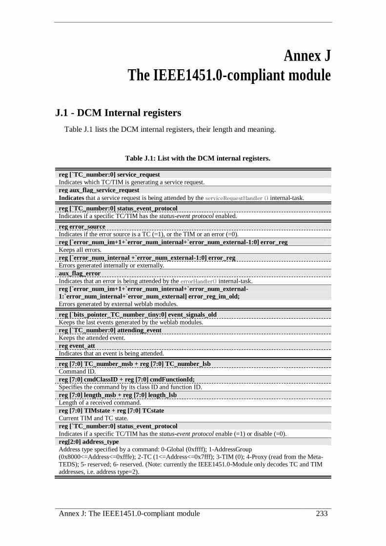
Annex J: The IEEE1451.0-compliant module 233
Annex J
The IEEE1451.0-compliant module
J.1 - DCM Internal registers
Table J.1 lists the DCM internal registers, their length and meaning.
Table J.1: List with the DCM internal registers.
reg [`TC_number:0] service_request
Indicates which TC/TIM is generating a service request.
reg aux_flag_service_request
Indicates that a service request is being attended by the serviceRequestHandler () internal-task.
reg [`TC_number:0] status_event_protocol
Indicates if a specific TC/TIM has the status-event protocol enabled.
reg error_source
Indicates if the error source is a TC (=1), or the TIM or an error (=0).
reg [`error_num_im+1+`error_num_internal+`error_num_external-1:0] error_reg
Keeps all errors.
reg [`error_num_internal +`error_num_external-1:0] error_reg
Errors generated internally or externally.
aux_flag_error
Indicates that an error is being attended by the errorHandler() internal-task.
reg [`error_num_im+1+`error_num_internal+`error_num_external-
1:`error_num_internal+`error_num_external] error_reg_im_old;
Errors generated by external weblab modules.
reg [`bits_pointer_TC_number_tiny:0] event_signals_old
Keeps the last events generated by the weblab modules.
reg [`TC_number:0] attending_event
Keeps the attended event.
reg event_att
Indicates that an event is being attended.
reg [7:0] TC_number_msb + reg [7:0] TC_number_lsb
Command ID.
reg [7:0] cmdClassID + reg [7:0] cmdFunctionId;
Specifies the command by its class ID and function ID.
reg [7:0] length_msb + reg [7:0] length_lsb
Length of a received command.
reg [7:0] TIMstate + reg [7:0] TCstate
Current TIM and TC state.
reg [`TC_number:0] status_event_protocol
Indicates if a specific TC/TIM has the status-event protocol enable (=1) or disable (=0).
reg[2:0] address_type
Address type specified by a command: 0-Global (0xffff); 1-AddressGroup
(0x8000<=Address<=0xfffe); 2-TC (1<=Address<=0x7fff); 3-TIM (0); 4-Proxy (read from the Meta-
TEDS); 5- reserved; 6- reserved. (Note: currently the IEEE1451.0-Module only decodes TC and TIM
addresses, i.e. address type=2).

234 An IEEE1451.0-compliant FPGA-based reconfigurable weblab
reg aux_flag; aux_flag2
reg [7:0] aux_octet_1; aux_octet_2; aux_octet_3
reg [31:0] aux_dw; aux_dw_2; aux_dw_3; aux_dw_4
Auxiliar registers. Note: aux_dw_2 can not be used in command-tasks since it is used by the
serviceRequestHandler() and errorHandler() internal-tasks that may run in parallel. If other tasks use these registers it will be generated an error during the synthesis of the weblab project.
reg [15:0] aux_checksum
Keeps the checksum calculation (used by the calculatesChecksum() internal-task).
reg [7:0] buffer_controller [`max_memlength+20:0]
Auxiliary register (keeps data read before send it to the UART-M).
reg [4:0] samplingMode
Specifies current sampling mode of the selected TC (field 31 of TC-TEDS / table 54 Std. of the
IEEE1451.0 Std.): - Trigger initiated mode (section 5.10.1.1 of the IEEE1451.0 Std.) = 1;
- Free-running without pre-trigger mode (section 5.10.1.2 of the IEEE1451.0 Std.) = 2;
- Free-running with pre-trigger mode(section 5.10.1.3 of the IEEE1451.0 Std.) = 4 (only valid for
sensors);
- Continuous Sampling mode (section 5.10.1.6 of the IEEE1451.0 Std.) = 8;
- Immediate operation sampling mode (section 5.10.1.7 of the IEEE1451.0 Std.) = 16.
reg [4:0] transmissionMode
Specifies current transmission mode of the selected TC (field 32 of TC-TEDS / table 58 Std. of the
IEEE1451.0 Std.):
- reserved = 1;
- commanded mode = 2 (Write/ReadTCDSSegment commands can be applied in this mode); - streaming when buffer (data set) if full = 4;
- streaming at a fixed interval = 8;
- all modes available = 16.
reg [7:0] state; state_2; state_3
Registers used for sequence control: state (controller), state_2 (subtasks states); state_3 (commands).
reg[7:0] state_rst
Used for sequence control the reset_task() internal-task.
reg [7:0] state_command_module
Used for sequence control of tasks in the TEDS-M and in the SSM internal controllers.
reg [3:0] error_state
Used for sequence control the errorHandler() internal-task.
reg [4:0] service_req_state
Used for sequence control the serviceRequestHandler() internal-task.
reg [31:0] teds_size
Auxiliary register used to keep the current TEDS size or the maximum TEDS size.
reg rst
After attending a command this signal is set to reset all relevant registers.
reg power_up
Indicates a power-up in the IEEE1451.0-Module.
reg flag_rst
Used to handle the reset/power-on.
reg flag_resetcommand
Handles the reset command IEEE1451.0 command.
reg end_task
Indicates if a specific task has ended.
reg end_tc_task
Indicates the end of a TC-task (e.g. init(), rd(), etc.).
reg end_access_TEDS, end_step_access_TEDS
Registers used to control the access to commands provided by the TEDS-M.
reg end_access_SS
Controls the access to commands provided by the SSM.

Annex J: The IEEE1451.0-compliant module 235
J.2 - DCM internal and command tasks
J.2.1 - Internal tasks
Table J.2 lists all the DCM internal-tasks used to manage its features. Command
tasks may communicate with these internal-tasks.
Table J.2: DCM internal-tasks.
test_length (input type; input [15:0] value)
Evaluates if the length of a received command, defined in the DCM internal registers {length_msb,
length_msb} have a length more or equal (type=1) or only equal (type=0) to the value defined in the
value register of this task. This task returns an error (error_reg [5]=1) if, according to the value defined
in the type register, the condition is not valid. The objective of this task is to evaluate if a received
command has the number of fields in accordance with the IEEE1451.0 Std.
createTIMMsg (input [15:0] id; input[7:0] class; input[7:0] function_; input [15:0] length;
input[7:0] wr_octet;)
Creates a generic TIM message structure according to the IEEE1451.0 Std. in the buffer_out_tx of the
UART-M. The use of this task requires the definition of the following parameters: id - TC/TIM ID;
class - command class ID; function_ - command function ID; length - message data structure length
(number of octets to send); wr_octet - octet to send. The end_task internal DCM register is set after
building the message structure.
createReplyMsg ( input flag, input [7:0]wr_octet, input[15:0] length)
Creates a reply message structure according to the IEEE1451.0 Std. in the buffer_out_tx of the UART-
M. The use of this task requires the definition of the following parameters: flag - indicates the value of
the flag used in a reply message structure (1-success, 0-fail); length - message data structure length
(number of octets to send); wr_octet - octet to send. The end_task internal DCM register is set after building the message structure.
errorHandler ( )
Establishes a map between all internal and external errors into the TIM/TC condition bit registers
defined within the status memory used in the SSM. At the end a reply message indicating an error will
be sent to the NCAP.
serviceRequestHandler ( )
If the status-event protocol is active, it sends a reply message with the event register of the TIM/TC.
Accessed when there is a SR generated by the SSM.
findMAP ( input type, input [7:0] tedsCode )
Consults the MT according to the value defined in the input parameters. The type register specifies the
way this task runs, and the tedsCode register indicates the TEDS ID code to find. Therefore, depending
on the type value, two operations may be defined for this internal-task:
1- type=’0’: verifies if the TC/TIM ID exists in the MT for the TC number specified by registers
TC_number_msb and TC_number_lsb. The tedsCode is not used (place at 0). If the TEDS ID code exists
in the MT, there is no error (error_reg [bit 0] gets 0), the octet_out_map gets the less significant octet of
the memory number associated to the specified TEDS ID code, and the address_map gets the address of
the MT pointing to that value. If the ID does not exist, the address_map gets 0 and the error_reg [bit 0] gets 1.
2- type=’1’: gets the memory number in the MT associated to the specified TEDS ID code defined in
the tedsCode. To specify how to get the memory number, the tedsCode can be specified in two different
ways: i) placed at 0, meaning that the TEDS ID code is automatically read from the received command message, or; ii) directly set with the TEDS ID code to find. If the TEDS ID code is found in the MT,
the address_map register gets the MT register address that specifies the associated memory number, the
octet_out_map indicates that memory number, and the error_reg [bit 3] gets 0, which means the
memory number associated to the specified TEDS ID code was found. If the TEDS ID code does not
exist in the MT, the address_map gets 0 and the error_reg [bit 3] gets 1.
calculatesChecksum (input [7:0] memNum, input [31:0] length)
Calculates the checksum of a TEDS, whose size is specified in the length register, and the
implementation is available in the memory number specified in the memNum register. The result of this task, which is the calculated checksum of the specified TEDS ID code, is placed in the first 2 octets of
the aux_dw_2 register.

236 An IEEE1451.0-compliant FPGA-based reconfigurable weblab
evaluatesDataSetLength ()
Evaluates if the WriteTCDSsegment and ReadTCDSsegment commands can be applied to a specific DS.
This command is used by these commands to evaluate if the offset defined in both fits in the length
defined to the DS, otherwise it generates errors that will be handled by the DCM.
It uses as inputs the: data_octet_out_map that has the number of the TEDS memory returned by the
findMap() task, the length_msb and length_lsb that have the length returned from the received message,
and the aux_dw that has the offset returned from the received command message. The output of this
task returns fields from the TC-TEDSs, namely the samplingLength (field 18) in the aux_octet_2
register, and the MaximumDataRepetitions (field 43) in the aux_dw_3 register.
resetTask (input caller_71reset)
Initializes all modules and each weblab module according the init() TC-tasks associated to the adopted
TC. This task is accessed in two cases: i) after the end of a command or ii) by issuing the reset
command. Within the task this two accesses are controlled by the register name caller_71reset. If the
access is made by the reset command, all SR are aborted (event registers are cleared). Note that the
TEDSs are not initialized with the default values.
initializeController
Initializes all DCM registers and it is accessed during a TIM power-up.
J.2.2 - Command-tasks
This annex presents in table J.3, table J.4, table J.5 and table J.6 all tasks with the
commands implemented by the IEEE1451.0-Module, divided according to their class
ID, identifying the HDL files where they were implemented.
Table J.3: Commands common to the TIM and to each TC (ClassID=1).
QueryTEDS (FunctionID=1) [file: 1_1_QueryTEDS.vh]
Used by the NCAP to solicit information required to read or write the TEDS. This command returns
the TEDS information fields defined in the TEDS structure (last 12 octets).
Arguments: TEDS ID code (8 bits).
Returns: TEDS’s fields information (e.g.:TEDS attributes, TEDS status, Current size of the TEDS, etc.). There are 4 possible replies defined according to the defined TEDS attributes (tables 18 and 19 of
the IEEE1451.0 Std.):
i)NotAvail=0 & Invalid=0 & Virtual=1: >>1,0,12,TEDS information;
ii) NotAvail=1 or Invalid=1: >>1,0,12, TEDS information (TEDSsize=MaxTEDSSize=0);
iii) NotAvail=0 or Invalid=0 & Virtual=1: >>1,0,12, TEDS information
(TEDSsize = MaxTEDSSize = TEDSCkSum=0);
iv) TEDS not located. An error is generated meaning that the TEDS access code or the ID does not
match/exist in the MT.
ReadTEDSsegment (FunctionID=2) [file: 1_2_ReadTEDSsegment.vh]
Reads a TEDS starting for a position defined according to an offset value.
Arguments: TEDS ID code (8 bits) and TEDS offset (32 bits).
Returns: The first field contains the offset at which the block of data in the TEDS was taken and will,
in most cases, match the TEDS segment offset in the ReadTEDSsegment command. The remaining octets contain the data read from the TEDS. If the TEDS offset is greater than the length of the TEDS,
the TEDS offset in the reply is equal to the TEDS length and the reply will contain 0 octets.
Notes:
1- The IEEE1451.0 Std. indicates “... TEDS are allowed to be larger than the maximum size of an octet
array. The transmission of these large TEDSs requires the segmentation of the TEDS for transmission
“. Therefore, if the TEDS segment has a length greater than the value defined in the parameter named
MAXIMUM_MSG_LENGTH (available in the 1_2_ReadTEDSsegment.vh file) it will be sent several reply
messages, since each one has a maximum length defined by the MAXIMUM_MSG_LENGTH.
2- Despite indicated by the IEEE1451.0 Std., the following issue was not implemented: “The reply
shall contain all ones in the TEDS segment offset and 0 data octets if the TEDS is “virtual,” is not
supported, or is invalid.”.

Annex J: The IEEE1451.0-compliant module 237
WriteTEDSsegment (FunctionID=3) [file: 1_3_WriteTEDSsegment.vh]
Used to write part of a TEDS.
Arguments: TEDS ID code (8 bits), TEDS offset (32 bits) and Raw TEDS block (N x 8 bits).
Returns:No reply, i.e. 100 (command correctly issued) or 000 (error issuing the command).
Notes:
1- Since the maximum size for an octet array is less than the maximum size for a TEDS, the TEDS
segment offset is used to identify where in the TEDS the Raw TEDS block should be written.
2- The IEEE1451.0 Std. indicates the following when data exceeds the TEDS size: “If the maximum
TEDS size is exceeded, the additional data shall not be written into the memory and the current size of
the TEDS shall be set to zero. If the TEDS offset is greater than the maximum length of the TEDS, the
data shall be discarded and the command rejected bit in the status word (section 5.13.4 of the
IEEE1451.0 Std.) shall be set.”. In current implementation this issue was simplified gathering both
conditions, i.e. in both situations the command rejected bit of the status word is set if no data is written into the TEDS and the length is not changed. An error message will be generated (000).
3- The IEEE1451.0 Std. indicates the following “A WriteTEDSsegment command shall create a new
TEDS if one does not already exist with that access code”. In current implementation the TIM does not
allow creating a new TEDS neither changing the length. To change the size of a TEDS it must be
issued a new command named WriteTEDSsize, since the standard is not clear on how to change the size of a new TEDS. Current implementation do not allow increasing the size of a TEDS, it only allows
reducing its size.
4- If the TIM is not designed to allow creating a new TEDS, the WriteTEDSSegment command shall not
write any data into a TEDS memory because the TEDS is unsupported.
5- When the TIM begins to overwrite an existing TEDS, this will be marked as Invalid. It shall remains
marked as Invalid (the TEDS attributes bit 2 (table 19 in the Std.) is set) until the UpdateTEDS command is received.
UpdateTEDS (FunctionID=4) [file: 1_4_UpdateTEDS.vh]
Validates a TEDS currently marked as invalid (WriteTEDS command updates a TEDS but it becomes
invalid, and it only becomes valid after issuing this UpdateTEDS command).
Arguments: TEDS ID code (8 bits).
Returns: returns the 4 possibilities similar to the reply of a QueryTEDS command.
Notes:
1- This command is used to validate a TEDS that was previously written into MB connected to the DCM. If it is valid, it is marked as valid in the state octet of the TEDS structure and it is copied into a
TEDS memory of the TEDS-M. Otherwise, the TEDS shall remain invalid and there is no copy.
2- In current implementation the TEDS validation consists on evaluating the checksum, by calculating
it according to the current data available in the TEDS and compares that calculation with the checksum
available within the TEDS. If they are equal, the TEDS is marked as valid, otherwise it remains
invalid.
3- This command automatically calls update_TC() TC-tasks, since a change in a specific TEDS may
change the operation of a weblab module connected to the TC.
WriteServiceRequestMask (FunctionID=6) [file: 1_6_WriteServiceRequestMask.vh]
Writes the SR mask register (32 bit word) for the addressed TC/TIM.
Arguments: SR Mask (32 bits).
Returns: No reply, i.e. 100 (command correctly issued) or 000 (error).
ReadServiceRequestMask (FunctionID=7) [file: 1_7_1_8_1_9_ReadMaskEventCondition.vh]
Reads the SR mask register from the addressed TC/TIM. Arguments: none. Returns: SR mask register.
ReadStatusEventRegister (FunctionID=8) [file: 1_7_1_8_1_9_ReadMaskEventCondition.vh]
Reads the event from the addressed TC/TIM.
Arguments: none; Returns: event register.
ReadStatusConditionRegister (FunctionID=9) [file: 1_7_1_8_1_9_ReadMaskEventCondition.vh]
Reads the condition register from the addressed TC/TIM.
Arguments: none Returns: condition register.
ClearStatusEventRegister (FunctionID=10) [file: 1_10_ClearStatusEventRegister.vh]
Clears the event register for the addressed TC/TIM.
Arguments: none.
Returns: No reply, i.e. 100 (command correctly issued) or 000 (error).
Note: If the address target is the TIM, the command clears all the event registers, i.e. from the TIM
itself and from all TCs. It does not clear the mask and condition registers.

238 An IEEE1451.0-compliant FPGA-based reconfigurable weblab
WriteStatusEventProtocolState (FunctionID=11) [file: 1_11_WriteStatusEventProtocolState.vh]
Enables or disables the status-event protocol. When this protocol is enabled, a TIM-initiated message
will send the 32 bit event register any time the SR bit is asserted, according to the status message
generation logic. Note that if it is a TC requesting a service, the event register will be sent. If it is the
TIM, it will be sent the TIM event register.
Arguments: Service enable bit (1- enable or 0-disable).
Returns: No reply, i.e. 100 (command correctly issued) or 000 (error).
WriteTEDSSize (FunctionID=128) ) [file: 1_128_WriteTEDSSize.vh]
This is a new command not defined in the IEEE1451.0 Std. that allows changing the TEDS size.
Arguments: TEDS access code (8 bits) and the new TEDS size (32 bits).
Returns: No reply, i.e. 100 (command correctly issued) or 000 (error).
Note: This new command was implemented because none of the IEEE1451.0 commands allow
changing the TEDS size and therefore the length of a TEDS can not be changed. This command was
especially created specially to change the size of a specific TEDS (the first 4 octets) and the TEDS
information (the last 12 octets of a TEDS structure). The TEDS remains invalid (bit 2 of TEDS
Attributes at '1') until the UpdateTEDS command is issued. If the new size exceeds the maximum TEDS
size, the command rejected bit in the condition register is set and an error reply is generated. Note that
the WriteTEDSsegment command only writes the data block and the checksum, but it does not allow
changing the length.
Table J.4: Transducer operating state commands (ClassID=3).
ReadTCDSsegment (FunctionID=1) [file: 3_1_ReadTCDataSetSegment.vh]
Reads segments from a DS belonging to a particular TC.
Arguments: Offset (32 bits).
Reply: The first field contains the offset at which the data segment was taken. The remaining octets
contain the data segment read from the DS. [1(1 octet), length (2 octets), offset (4 octets), data (n
octets)]. Notes:
1- The maximum size for an octet array that may be handled by a given physical transport layer is less
than the maximum size for a DS.
2- The reply contains all ones in the DS segment offset and 0 data octets if the DS is empty.
3- If the offset is greater than the number of octets in the DS, the offset field in the reply will be equal
to the maximum number of octets in the DS and the reply will contain 0 octets.
4- When this command is received and a TC is being operating in a streaming data transmission modes
(section 5.10.2 of Std.), the command rejected bit in the condition register (section 5.13.4 of the
IEEE1451.0 Std.) will be set and the command will be ignored.
5- If the destination TC number in the octet array is zero, the command rejected bit in the TIM
condition register (section 5.13.4 of the IEEE1451.0 Std.) will be set and the command ignored.
6- At the end, the global register named aux_dw will get the offset value of the read data segment.
7- This command automatically calls the rd() and update() TC-tasks.
WriteTCDSsegment (FunctionID=2) [file: 3_2_WriteTCDataSetSegment.vh]
Writes segments into a DS belonging to a particular TC.
Arguments: Offset (32 bits) and a set of data (N x 8 bits).
Returns: No reply, i.e. 100 (command correctly issued) or 000 (error).
Notes:
1- The maximum size for an octet array that may be handled by a given physical transport layer is less than the maximum size for a data set.
2- If the defined offset is greater than the maximum length of the DS (defined in the TC-TEDS Max.
data repetition field (section 8.5.2.28 of the IEEE1451.0 Std.)) the data will be discarded and the
command rejected bit in the status word (section 5.13.4 of the IEEE1451.0 Std.) will be set.
3- When this command is received and a TC is operating in a streaming data transmission mode
(section 5.10.2 of the IEEE1451.0 Std.), the command rejected bit (section 5.13 of the IEEE1451.0
Std.) in the condition register will be set and the command will be ignored.
4- If the destination TC number in the octet array is zero, the command rejected bit (5.13 of the
IEEE1451.0 Std.) in the TIM condition register will be set and the command will be ignored.
5- The command rejected bit (section 5.13 of the IEEE1451.0 Std.) is also set if this command is sent
to a TC defined as a sensor or to an event sensor.
6- At the end the global register named aux_dw will get the offset and the aux_dw_3 will get the
Maximum Repetition Field (defined in the TEDS-TC fields 19 and 43).

Annex J: The IEEE1451.0-compliant module 239
7- This command automatically calls the wr() and the update() TC-tasks.
TriggerCommand (FunctionID=3) [file: 3_3_4_TriggerCommand_AbortTrigger.vh]
Sends a trigger signal to start the operation controlled by a TC. This command will be ignored for TCs
in immediate sampling mode or in situations where the trigger is disabled.
Arguments: none.
Returns: No reply, i.e. 100 (command correctly issued) or 000 (error).
AbortTrigger (FunctionID=4) [file: 3_3_4_TriggerCommand_AbortTrigger.vh]
Sends a trigger signal to stop the operation controlled by a TC. This command will be ignored for TCs
in immediate sampling mode or in situations where the trigger is disabled.
Arguments: none.
Returns: No reply, i.e. 100 (command correctly issued) or 000 (error).
Table J.5: Transducer either idle or operating state commands (ClassID=4).
TCOperate (FunctionID=1) [file: 4_1_a_4_2_TC_Operate_and_Idle.vh]
Sets a TC from Idle to Operating state. If it is already in the Operating state the command will be
ignored.
Arguments: none.
Returns: No reply, i.e. 100 (command correctly issued) or 000 (error).
TCIdle (FunctionID=2) [file: 4_1_a_4_2_TC_Operate_and_Idle.vh]
Sets a TC to an Idle state. If it is already in the Idle state the command will be ignored.
Arguments: none.
Returns: No reply, i.e. 100 (command correctly issued) or 000 (error).
WriteTCTriggerState (FunctionID=3) [file: 4_3_ WriteTCTriggerState.vh]
Enables/Disables the triggering of a specific TC. Arguments: trigger state (bit).
Returns: No reply, i.e. 100 (command correctly issued) or 000 (error).
Notes:
1- If the TC does not support sampling modes without triggers, i.e. the immediate operation sampling
mode (section 5.10.1.7 of the IEEE1451.0 Std.), the command rejected bit in the condition register
(section 5.13.4 of the IEEE1451.0 Std.) will be set and the command will be ignored.
2- The indication that a specific TC is enabled/disabled is provided by the associated octet in the state
memory trigger octet provided by the SSM.
3- The argument should be 0 or 1, otherwise the command rejected bit in the status register (section
5.13.4 of the IEEE1451.0 Std.) will be set.
ReadTCTriggerState (FunctionID=4) [file: 4_4_ ReadTCTriggerState.vh]
Reads the trigger state of the current TC.
Arguments: none. Returns: Current trigger state (trigger octet less significant bit indicating if it is enabled (1) or disabled
(0)).
Notes:
1- If the current TC does not support triggering, i.e. the sampling mode is immediate, the reply will be
false (disabled = 0).
2- The indication that a specific trigger state is enabled/disabled is provided by the associated octet on
the state memory trigger octet provided by the SSM.
Table J.6: TIM any state commands (ClassID=7).
Reset (FunctionID=1) [file: 7_1_Reset.vh]
Resets the TIM and all TCs.
Arguments: none.
Returns: No reply, i.e. 100 (command correctly issued) or 000 (error issuing the command).
Notes:
1- Initializes all TCs resetting all SRs and accesses the init() and the reset() TC-tasks.
2- The TEDS-M and the SSM memories can only by reinitialized by the entire FPGA reinitialization.

240 An IEEE1451.0-compliant FPGA-based reconfigurable weblab
J.3 - DCM schematics
Figure J.1 presents the connections and associated buses and lines adopted by the
DCM. Some of these buses have a variable width redefined during the reconfiguration
process, since they depend on the number of adopted TEDSs and TCs for connecting
the weblab modules. The role of each bus and line is described in the remaining annexes
that detail the other modules’ functionalities.
address_mod
en_map
address_map
octet_out_map [7:0]
clk
octet_out_rx
rd_rx
rst_rd_rx
rst_rx
available_rd_rx
octet_in_tx
wr_tx
rst_wr_tx
wr_active_tx
available_wr_tx
ReplyTIM_msg_tx
double_word_in_mod
double_word_out_mod
service_request_mod
en_ss_mod
end_mod
run_mod
exec_mod
done_mod
select_mod
access_mod
en error
tx_send_tx
rst_tx
rd_active_rx
[7:0]
[7:0]
external errors (UART-M, TEDS-M and SSM)
[31:0][31:0]
Δ
[2:0]
error_reg
internal errors
en_teds_mod
reset
en_buffer
address_buffer
octet_out_buffer
octet_in_buffer
wr_buffer
clk
octet_outoctet_inaddress
wr
en
[7:0][7:0]
clk
Δ
enaddress
octet_out
Map
Table (MT)
Δ
MemoryBuffer (MB)
rst_mod
Tasks for
accessing TCs
(TC-tasks)
UART-M
TEDS Module
(TEDS-M)&
Status/State
Module(SSM)
I&MI&MWeblab module
TCs
Note: Δ means a
variable width
defined during the
reconfiguration
Δ
push-button
Δ
Δevent signals
Δ
BR_generatorCLK
FPGA
CLK FPGA
clk
clk
internal-taskscommand-tasks
Decoder
Controller
Module
(DCM)
clk
Figure J.1: DCM schematics with all adopted buses for interfacing the other modules.
J.4 - The DCM-MB interface
The DCM-MB interface depends on the size of the MB. This is specified in the
configuration file (*.conf) selected during the reconfiguration process that defines
internal parameters in the definitions_GENERIC.vh file automatically created by the
RecTool, namely: the max_mem_buffer (defines the length of the MB) and the

Annex J: The IEEE1451.0-compliant module 241
bits_max_mem_buffer (specifies the width of an address_buffer bus used to access the
MB). Table J.7 presents code examples defined in both files (*.conf and
definitions_GENERIC.vh) used to define the MB.
Table J.7: MB definition (pieces of code in *.conf and definitions_GENERIC.vh files).
*.conf
<mem_buffer>
100
</mem_buffer> definitions_GENERIC.vh
`define max_mem_buffer 100
`define bits_max_mem_buffer 7 //>=(log[2])
The MB is internally accessed by the DCM using a point-to-point connection
established by the buses ending with the prefix _buffer, described in table J.8.
Table J.8: Buses and lines adopted for the DCM-MB interface.
line operation
en_buffer Enables the access to the memory buffer (1 line - output).
address_buffer Specifies the MB address to read/write (variable length - output).
wr_buffer Indicates if the MB will be read (1) or written (0) (1 line - output).
octet_in_buffer Specifies the data to write into the MB (8 lines - output).
octet_out_buffer Gets the data read from the MB (8 lines - input).
The DCM accesses the MB using: i) IEEE1451.0 commands or; ii) the TC-tasks
associated to a weblab module. Since these TC-tasks will be described by the
developers of the weblab modules, they must know how to access the contents of the
MB. For this purpose, table J.9 presents the Verilog HDL code that enables controlling
the referred buses according to a particular state sequence.
Table J.9: Sequence for accessing to the MB (Verilog code examples).
Read operation (…)
2:begin address_buffer<=address to read; state<=3; end
3:state<=4; // required delay
4:begin octet_out_buffer has the data available in the address_buffer position …
(…) handle data read and then update the address_buffer position to read new data…
(…) state<=2;
(note: before enabling the MB (en_buffer<=1) the MB must be in a read state (wr_buffer=0).
Write operation (…)
2:begin en_buffer<=1; address_buffer<= new address to writestate<=3; end
3:begin (…) octet_in_buffer<= new datastate<=4; end
4:begin wr_buffer<=1;state<=5; end
5:begin wr_buffer<=0;state<=2; end
(note: the address_buffer register must be defined before rising the wr_buffer signal)

242 An IEEE1451.0-compliant FPGA-based reconfigurable weblab
J.5 - The DCM-MT interface
The MT is automatically created by the RecTool according to the *.map file defined
by the users. Its contents can be accessed by managing a set of buses and lines with the
prefix _map, each with its specific role specified in table J.10.
Table J.10: Buses and lines adopted for the DCM-MT interface.
line operation
en_map Enables the access to the MT (1 line - output).
address_map Specifies the MT address field to read (variable length - output).
octet_out_map Data read from the MT (8 lines - input).
The MT is accessed using the DCM internal-task named findMAP() that consults its
contents according to the current TC ID and TEDS ID code, and returns the memory
number associated to that particular TEDS. The access to its contents is exclusively
made by this internal-task. Table J.11 presents the Verilog HDL state sequence required
to read the MT.
Table J.11: Sequence for reading the MT (Verilog code example).
Read operation (…)
2:begin en_map<=1; address_map<=address to read; state<=3; end
3:state<=4; // required delay
4:begin octet_out_map has the data available in the address_map position
(…) state<=2; Write operation
Not implemented. The MT can not be changed (it is synthesized to a ROM).
J.6 - DCM registers and buses for implementing the error
detection mechanism
As illustrated in figure J.2, the error sources handled by the DCM are included into
the internal register named error_reg, divided in three parts, whose lengths are defined
during the reconfiguration process in different variables:
part_1 (error_internal) - internal errors generated by the DCM (the length is
defined by the variable error_num_internal);
part_2 (error_external) - external errors generated by the external modules (the
length is defined by the variable error_num_external);
part_3 (error_im) - errors generated by the weblab modules (the length is
defined by the variable error_num_im);
part_1 + part_2 + part_3 - have all errors (the length is the sum of the variables
error_num_internal, error_num_external and error_num_im).

Annex J: The IEEE1451.0-compliant module 243
enerror
reset
clk
error_im
error
weblab
module
8*8*
error_imerror_external
error_internal
Internal errors generated by
the DCM
Interface
DCMUART-M
TEDS-M
Status/
State-M
0,1
6,7
2,3,4,5
external errors
error lines of the weblab modules
error_im[]
* - for new versions of the IEEE1451.0-Module
these values can be changed in the
`error_num_external and `error_num_internal
variables defined in the defenitions.vh file
Δ
Δ+8*
10*
error_reg
Figure J.2: Illustration of the adopted registers to handle errors.
When new weblab modules are bound to the IEEE1451.0-Module, the width of the
error_reg register should be increased by incrementing the variable `error_num_im
according to the number of new errors those modules may generate. Each weblab
module may have several dedicated error lines connected to the DCM using a bus
named error_im[]. All these definitions are made in the configuration file (*.conf) by
the tag named <im_errors>.
J.7 - Error codes specified in the IEEE1451.0-Module
Table J.12 provides the mapping established between the error codes specified
internally for the IEEE1451.0-Module, namely the error_reg register, and the
IEEE1451.0 errors specified in the condition register of the TC/TIM.
Table J.12: Error codes mapped from the condition register to the error_reg.
error_
reg
(bit)
sou
rce
Cause for the generated error
IEEE1451.0 error
code description
0
DC
M
ID does not exist. 3* Command rejected
1 Command class does not exist. 2 Invalid command
2 Command function does not exist.
3
- TEDS access code or ID does not match/exist in the
MT.
- TEDS is read only and it cannot be written.
- TEDS miss a required field or TEDS is invalid.
- Data does not fit into the TEDS memory.
- New TEDS size exceeds the Maximum TEDS size.
3 Command rejected
4 Command cannot be applied for the current TC/TIM states or the length in the command message structure is
invalid.
8 Protocol error
5 Length specified for a specific command is invalid. 3 Command rejected
6 Modules desynchronized or a specific task is missing for
the target TC. 6,7
Hardware & Not
operational errors
7 - not implemented - reserved.
8
Command not implemented for the selected TC or there
are some inconsistency issuing the command (e.g. data
does not fit into the MB).
3 Command rejected
9 Invalid sampling mode for TC. 6 Hardware error
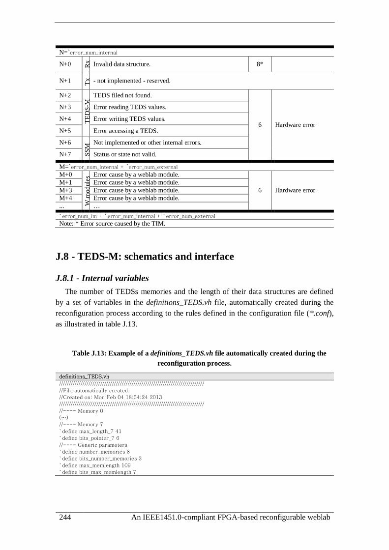
244 An IEEE1451.0-compliant FPGA-based reconfigurable weblab
N=`error_num_internal
N+0 Rx
Invalid data structure. 8*
N+1 Tx
- not implemented - reserved.
N+2
TE
DS
-M TEDS filed not found.
6 Hardware error
N+3 Error reading TEDS values.
N+4 Error writing TEDS values.
N+5 Error accessing a TEDS.
N+6
SS
M Not implemented or other internal errors.
N+7 Status or state not valid.
M=`error_num_internal + `error_num_external
M+0
W.m
odule
s Error cause by a weblab module.
6 Hardware error
M+1 Error cause by a weblab module.
M+3 Error cause by a weblab module.
M+4 Error cause by a weblab module.
... …
`error_num_im + `error_num_internal + `error_num_external
Note: * Error source caused by the TIM.
J.8 - TEDS-M: schematics and interface
J.8.1 - Internal variables
The number of TEDSs memories and the length of their data structures are defined
by a set of variables in the definitions_TEDS.vh file, automatically created during the
reconfiguration process according to the rules defined in the configuration file (*.conf),
as illustrated in table J.13.
Table J.13: Example of a definitions_TEDS.vh file automatically created during the
reconfiguration process.
definitions_TEDS.vh //////////////////////////////////////////////////////////////////////////
//File automatically created.
//Created on: Mon Feb 04 18:54:24 2013
//////////////////////////////////////////////////////////////////////////
//---- Memory 0
(…)
//---- Memory 7
`define max_length_7 41
`define bits_pointer_7 6
//---- Generic parameters
`define number_memories 8
`define bits_number_memories 3
`define max_memlength 109
`define bits_max_memlength 7

Annex J: The IEEE1451.0-compliant module 245
J.8.2 - Schematics and signals
Internally, the TEDS-M comprises a set of modules and multiplexers represented in
figure J.3. The DCM-TEDS-M interface is made through a set of commands according
to a particular handshake protocol using a set of buses and lines specified in table J.14.
select
access[2-0]
octet_in[7-0]
run
exec
Controller Memories
(TEDSs)
octet_in
address
wr
en
octet_out
address
en en
address_0address_1
address_n(...)
data_mem_in
data_mem_in_0
data_mem_in_1
(...)
data_mem_in_n en[0]
clk_mem
clk_mem
data_mem_out
error[3-0]
end_
done
octet_out
clk
wr
octet_out_0octet_out_1
(...)octet_out_n
en_mod
reset
rst
[7-0]
DCM
8
8
Δ
Δ
Δ*
Note: Δ: variable length , Δ*: [number_memories-0]
Multiplexer
Δ
8
8
TEDS-M
Figure J.3: TEDS-M internal schematics.
Table J.14: Buses and lines adopted for the DCM-TEDS-M interface.
line operation
exec, done,
run, end Control the module according to a specific handshake protocol (1 line each - I/O).
access Specifies command codes (3 lines - input).
select Specifies the memory number (length dependent on the maximum TEDS’s length
or the maximum data to transmit between the DCM and a weblab module - input).
octet_in / _out Transfer data between each TEDS and the DCM (8 lines - I/O).
error
Provides the TEDS-M error codes (4 lines - output) to handle unexpected
situations, such as reading an undefined field. All error are identified in the TEDS-
M according to 4 error codes defined in the DCM error_reg register as external
errors mapped into IEEE1451.0 errors representing the following: error [0] -
TEDS’s field not available; error [1] - reading TEDSs values; error [2] - writing
TEDS’s values; error [3] - command not implemented.
rst Issues a command (1 line - input).
reset Resets the controller, but the TEDSs contents are not recovered (1 line - input).
en_mod Turns-on the entire TEDS-M (1 line - input).
clk Clock signal (1 line - input).

246 An IEEE1451.0-compliant FPGA-based reconfigurable weblab
J.8.3 - Handshake protocol
The handshake protocol used to access the TEDS-M is illustrated in figure J.4. This
is synchronized by the internal clk line and managed by the DCM using the exec, done,
run and end lines. These lines enable issuing commands to the TEDS-M, by executing
operations (execute operation), which may be applied in steps sequences (step
operations) when the associated data sent/retrieved with the command uses more than
one octet. This data is placed in the octet in/out buses that have a limited length of 8
lines. In this situation, after triggering an operation using a command (run signal is
high), the octet_in/out buses are read/write more than once, according to the execution
of step sequences controlled by the exec and the done lines until the end line goes up,
i.e. the last octet was read/wrote.
The controller accesses (reads/writes) a particular TEDS according to a multiplexing
schema controlled by the en bus, when a specific command is issued. Based on the
value defined in this bus, which is managed by an internal register whose length
depends on the number of adopted TEDSs, a specific line in this bus is set, connecting
the data buses data_mem_in/out and the address bus to a particular TEDS. Since the
IEEE1451.0-Module is able to be reconfigured according to the adopted number of
TCs, which requires a variable number of TEDS, the lines en and address may have
different lengths. This process is transparent for the applied command, since both the
DCM and the TEDS-M manage all this process.
run
end
octet_in/out
access / select
exec
done
octet_in/out
access / select
run
op
era
tio
nst
epo
per
ati
on
operation ended
operation started
execute step-operation
step-operation ended
operation
clkDCM TEDS-M
run
end
exec
done
octet_in
access
octet_outselect
Figure J.4: Handshake protocol adopted for the DCM-TEDS-M interface.
J.8.4 - Hardware API
The hardware API provided for facilitating the access to the TEDS-M is
implemented in the Access_ModTEDS.vh file. It provides a set of instructions listed in
table J.15. Each instruction has a set of input parameters defined between parentheses,
which are basically DCM internal registers. Most of the instructions provide changes in

Annex J: The IEEE1451.0-compliant module 247
the DCM register named double_word_in_mod associated to their output. The void word
means that the associated instruction does not provide changes in any relevant DCM
register able to use as an output.
Table J.15: TEDS-M hardware API instructions (available in file:
Access_ModTEDS.vh).
double_word_out_mod ModTEDS_ReadField (select, octet_in)
select - memory number (3 bits - input).
octet_in - field number to read (8 bits - input).
double_word_out_mod - keeps fields read after the TEDSs’ length (32 bits - output).
double_word_out_mod ModTEDS_ReadWithOffset (select, double_word_offset)
select - memory number (3 bits - input).
double_word_offset - offset value that means the first octet to be read (32 bits - input).
double_word_out_mod - value read from the location specified by the offset (32 bits - output).
double_word_out_mod ModTEDS_QueryStatus (select)
select - memory number (3 bits - input).
double_word_out_mod - keeps the read status register (32 bits - output).
double_word_out_mod ModTEDS_FindField (select, octet_in)
select - memory number (3 bits - input). octet_in - field type number to find (8 bits - input).
double_word_out_mod - indicates if the field type was found (=1) or not found (=0) (32 bits but only
the less significant bit is relevant - output).
void ModTEDS_WriteField (select, octet_in, octet_in_data)
select - memory number (3 bits - input).
octet_in - field type number to write (8 bits - input).
octet_in_data - value to write in the specified field type number (8 bits - input).
void ModTEDS_WriteWithOffset (select, double_word_offset, octet_in_data)
select - memory number (3 bits - input).
double_word_offset - offset value means the first octet to be written (32 bits - input).
octet_in_data - value to write in the location specified by the offset (8 bits - input).
void ModTEDS_WriteStatus (select, octet_in_data)
select - memory number (3 bits - input).
octet_in_data - value to write in the status register (8 bits - input).
To use the hardware API instructions, specific state sequences defined in Verilog
HDL must be implemented. Table J.16 provides those sequences, which are controlled
by the state register and managed by the state_command_module, the end_access_TEDS,
and the end_step_access_TEDS registers.

248 An IEEE1451.0-compliant FPGA-based reconfigurable weblab
Table J.16: Sequences for accessing the TEDS-M hardware API instructions.
ReadField / QueryStatus / ReadWithOffset 0:begin state_command_module<=0; end_access_TEDS<=0; end_step_access_TEDS<=0; state<=1; end
1:begin if (end_access_TEDS==1) state<=leaves the sequence; //command ended
else begin ModTEDS_Read ()/ QueryStatus () /*double_word_out_mod updated*/ state<=2; end
end
2:begin if(end_step_access_TEDS==1) state<=3; //step ended (command NOT ended)
else state<=1;
end
3:begin /* data available in the double_word_out_mod can be handled here */
state<=1; //repeats a step sequence to read another field (QueryStatus only gets one field)
end (....)
FindField 0: begin state_command_module<=0; end_access_TEDS<=0; end_step_access_TEDS<=0; state<=1; end
1: begin ModTEDS_FindField(); /* double_word_out_mod goes to 1 if found or 0 if not found */
if (end_access_TEDS==1) state<= leaves the sequence; //command ended
end (....)
WriteField / WriteStatus / WriteWithOffset 0: begin state_command_module<=0; end_access_TEDS<=0; end_step_access_TEDS<=0;
value2Write<= ...first value to write....; state<=1;
end
1:begin if (end_access_TEDS==1) state<= leaves the sequence; /*command ended*/
else begin ModTEDS_Write./ WriteStatus (...value2Write...); state<=2; end
end
2:begin if(end_step_access_TEDS==1) state<=3; else state<=1;/*step ended (command NOT ended)*/ end
3:begin value2Write<= ...updates value to write... state<=1; end (...)
Note: value2Write is an 8 bit length register used to keep the new value to be written into a TEDS’s structure.
J.9 - SSM: schematics and interface
J.9.1 - Internal variables
The length of the status and state memories are defined during the reconfiguration
process according to the rules defined in the configuration file (*.conf). Their lengths
and address buses are specified in the definitions_GENERIC.vh file by the variables
bits_pointer_TC_number and bits_pointer_TC_number_small, whose values depend on
the number of adopted TCs defined in a variable named TC_number. While the
TC_number is defined according to a value specified in the configuration file, the others
are the result of a log base 2 mathematic calculation made during the reconfiguration
process, as exemplified in definitions_GENERIC.vh presented in table J.17.
Table J.17: Example of a definitions_GENERIC.vh file automatically created during the
reconfiguration process.
definitions_Generic.vh //////////////////////////////////////////////////////////////////////////
//File automatically created.
//Created on: Mon Feb 04 18:54:34 2013
//////////////////////////////////////////////////////////////////////////
`define TC_number 3
`define bits_pointer_TC_number 4 //>=(log[2](TC_number+1)*3)
`define bits_pointer_TC_number_small 3 //>=(log[2](TC_number+1)*2)
(…)

Annex J: The IEEE1451.0-compliant module 249
J.9.2 - Schematics and signals
Internally, the SSM comprises a set of modules and multiplexers represented in
figure J.5. The DCM-SSM interface is made according to a particular handshake
protocol using a set of buses and lines specified in table J.18.
access[1-0]
double_word_in[31-0]
address
en_memen_mem
address_1
address_0
double_word_
mem_in double_word_mem_in_1
octet_mem_in_0
clk_mem
double_word_mem_
out
error[1-0]
clk
wr_mem
octet_mem_out_0
double_word_mem_out_1
service_request
# TC+TIM
status[1]
double_word_in
addresswr
en
double_word_out
clk_mem
octet_inaddress
wr
en
octet_out
clk_mem
not
double_word_
out
en_mod
resetrst
runend_
[31-0]
state[0]
execdone
address_in
8
32
32
Δ1Δ1
Δ2Δ1
32
DCM
Controller
Multiplexera
a
a
b
b
b
c
cd
d
Notes: a: bus length=1; b: bus length=1; c: bus length=8; d: bus length=32. Δ1: bus length=bits_pointer_TC_number [number_memories-0]Δ2: bus length=bits_pointer_TC_small_numberstatus memory has 32-bits wide // state memory has 8-bits wide
SSM
Figure J.5: SSM internal schematics.
Table J.18: Buses and lines adopted for the DCM-SSM interface.
line operation
exec, done,
run, end Control the module according to a specific handshake protocol (1 line each - I/O).
access Specifies command codes (2 lines - input).
address_in Specifies the address of the selected memory (length dependent on the number of TCs -input).
double_word_in
ouble_word_out Buses used to transfer data between each memory and the DCM (32 lines - I/O).
service request Indicates that a SR was generated by a TC/TIM (1 line - output).
error
Provides SSM error codes (2 lines - output). The SSM may generate 2 errors
defined in the DCM error_reg as external errors, which will be mapped to
IEEE1451.0 errors representing the following: error [0] - command not
implemented, or any other types of internal errors; error [1] - transition between
states are not valid or invalid access to a status register.
rst Issues a command (1 line - input).
reset Resets the SSM controller, but the memories contents are not recovered (1 line -
input).
en_mod Turns-on the SSM (1 line - input).
clk Clock signal (1 line - input).
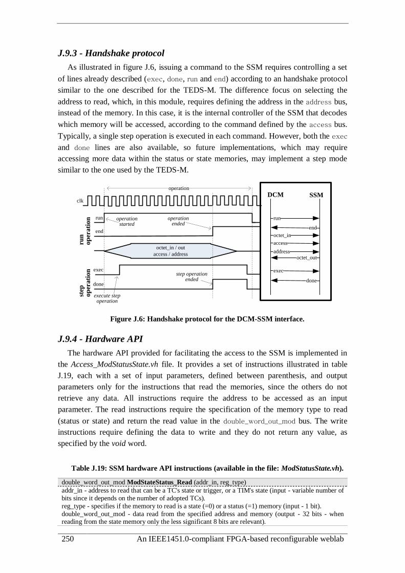
250 An IEEE1451.0-compliant FPGA-based reconfigurable weblab
J.9.3 - Handshake protocol
As illustrated in figure J.6, issuing a command to the SSM requires controlling a set
of lines already described (exec, done, run and end) according to an handshake protocol
similar to the one described for the TEDS-M. The difference focus on selecting the
address to read, which, in this module, requires defining the address in the address bus,
instead of the memory. In this case, it is the internal controller of the SSM that decodes
which memory will be accessed, according to the command defined by the access bus.
Typically, a single step operation is executed in each command. However, both the exec
and done lines are also available, so future implementations, which may require
accessing more data within the status or state memories, may implement a step mode
similar to the one used by the TEDS-M.
run
end
octet_in / out
access / address
exec
done
run
op
era
tio
nst
epo
per
ati
on
operation ended
operation started
execute step operation
step operation ended
operation
clkDCM SSM
run
end
exec
done
octet_in
access
octet_outaddress
Figure J.6: Handshake protocol for the DCM-SSM interface.
J.9.4 - Hardware API
The hardware API provided for facilitating the access to the SSM is implemented in
the Access_ModStatusState.vh file. It provides a set of instructions illustrated in table
J.19, each with a set of input parameters, defined between parenthesis, and output
parameters only for the instructions that read the memories, since the others do not
retrieve any data. All instructions require the address to be accessed as an input
parameter. The read instructions require the specification of the memory type to read
(status or state) and return the read value in the double_word_out_mod bus. The write
instructions require defining the data to write and they do not return any value, as
specified by the void word.
Table J.19: SSM hardware API instructions (available in the file: ModStatusState.vh).
double_word_out_mod ModStateStatus_Read (addr_in, reg_type)
addr_in - address to read that can be a TC's state or trigger, or a TIM's state (input - variable number of
bits since it depends on the number of adopted TCs).
reg_type - specifies if the memory to read is a state (=0) or a status (=1) memory (input - 1 bit).
double_word_out_mod - data read from the specified address and memory (output - 32 bits - when reading from the state memory only the less significant 8 bits are relevant).

Annex J: The IEEE1451.0-compliant module 251
void ModState_Write (addr_in, octet_in_data)
addr_in - address to write that can be a TC's state or trigger, or a TIM's state (input - variable number
of bits since it depends on the number of adopted TCs).
octet_in_data - data to write into the specified address of the state register (input - 8 bits).
void ModStatus_Write (addr_in , doubleWord_in_data)
addr_in - address to write the condition, event or mask registers (input - variable number of bits since it
depends on the number of adopted TCs).
double_word_in_data - data to write to the specified address of the status register (input - 32 bits).
To use the instructions of the hardware API, specific state sequences defined in
Verilog HDL must be implemented. Table J.20 provides those sequences, which use the
end_access register to manage a sequence controlled by the state register.
Table J.20: Sequences for accessing the SSM hardware API instructions.
Read Status / Read State 0: begin state_command_module<=0; end_access_SS<=0; state<=1; end
1: begin ModStateStatus_Read(addr_in, reg_type); // double_word_out_mod is updated
if(end_access_SS==1) //command ended
begin /*...do something with data and leaves */ state<=leaves the sequence; end
end (...)
Write State 0: begin state_command_module<=0; end_access_SS<=0; state<=1; end
1: begin ModState_Write(address position , octet data to write);
if(end_access_SS==1) state<=leaves the sequence;
end (...)
Write Status 0: begin state_command_module<=0; end_access_SS<=0; state<=1; end
1: begin ModStatus_Write(address position, doubleWord_in_data to write);
if(end_access_SS==1) state<=leaves the sequence;
end (...)
J.10 - UART-M: schematics and interface
J.10.1 - Schematics and signals
The UART-M sends/receives message structures to/from the NCAP. While
command messages are always sent from the NCAP, the TIM may send reply or TIM-
initiated messages to the NCAP. Each of those messages has its own data structure. The
distinction between them is made by the line named replyTIM_msg controlled by the
DCM. The frequency is defined during the reconfiguration process, using the variables
bps_divisor and bps_length_counter, whose values are specified according to the internal
oscillator implemented in the FPGA-based board.
Figure J.7 illustrates the internal modules of the UART-M, which comprises the Rx,
Tx and the BR_Generator modules, and the adopted buses and lines are detailed in table
J.21 and table J.22.

252 An IEEE1451.0-compliant FPGA-based reconfigurable weblab
rx
octet_out
rd_active
error
clkbuffer
_in
_rx
available_rd
rd
rst_rd
Rx
enable
rst_rx
clk_in clk_outf_clk/bps=`bps_divisor
BR_Generator
tx
octet_in
wr_active
error
clkbuffer
_out
_tx
available_wr
wr
rst_wr
Tx
enable
rst_tx
tx_send8 8
replyTIM_msg
Figure J.7: Modules of the UART-M and its buses and lines.
Table J.21: Signals used by the Rx module (data reception from the NCAP).
line operation
Handshake signals
available_rd Goes high when there is data in the buffer_in_rx. When the NCAP starts sending
that data, this signal goes low until all data were transmitted (1 line - ouput).
rd (pulse) Reads an octet from the buffer_in_rx (1 line - input).
rst_rd Used with the rd signal, resets the address position of the buffer_in_rx (1 line - input).
rd_active Goes high when data is being sent through the octet_out bus or goes low when all
octets were read (1 line - output).
Remaining signals
octet_out Bus used to read data available in the buffer_in_rx (8 lines - output).
error
Goes up when data received through Rx is not in accordance to the IEEE1451.0
Std. data structure. Internally the Rx module evaluates if the length specified in the
length field of the data structure is coherent with the remaining data, and if the
number of start and stop bits are correct (1 line output).
rx Receives data from the NCAP (1 line - input).
rst_rx Resets the Rx module (1 line - input).
clk Clock signal (1 line - input).
enable Enables the Rx module (1 line - input).
Table J.22: Signals used by the Tx module (data transmission to the NCAP).
line operation
Handshake signals
available_wr Goes high when data available in the buffer_out_tx is in accordance with the IEEE1451.0 Std. data structure and, therefore, able to be transmitted to the NCAP
(1 line - output).
wr (pulse) Writes an octet into the buffer_out_tx (1 line - input).
rst_wr Used with the wr signal, resets the address of the buffer_out_tx (1 line - input).
wr_active Goes high when data is being transmitted by the Tx module and it goes low when
the last octet is transmitted (1 line - output).
replyTIM_msg Indicates which type of message will be transmitted: TIM-initiated message (=0) or
a command reply message (=1) (1 line - input).
tx_send Initiates data transmission through the tx line (1 line - input).
Remaining signals
octet_in Bus used to write data into the buffer_out_tx (8 lines - input).
error Not implemented - reserved (1 line - output).
tx Transmits data to the NCAP (1 line - output).
rst_tx Resets the Tx module (1 line - input).
clk Clock line (1 line - input).
enable Enables the Tx module (1 line - input).
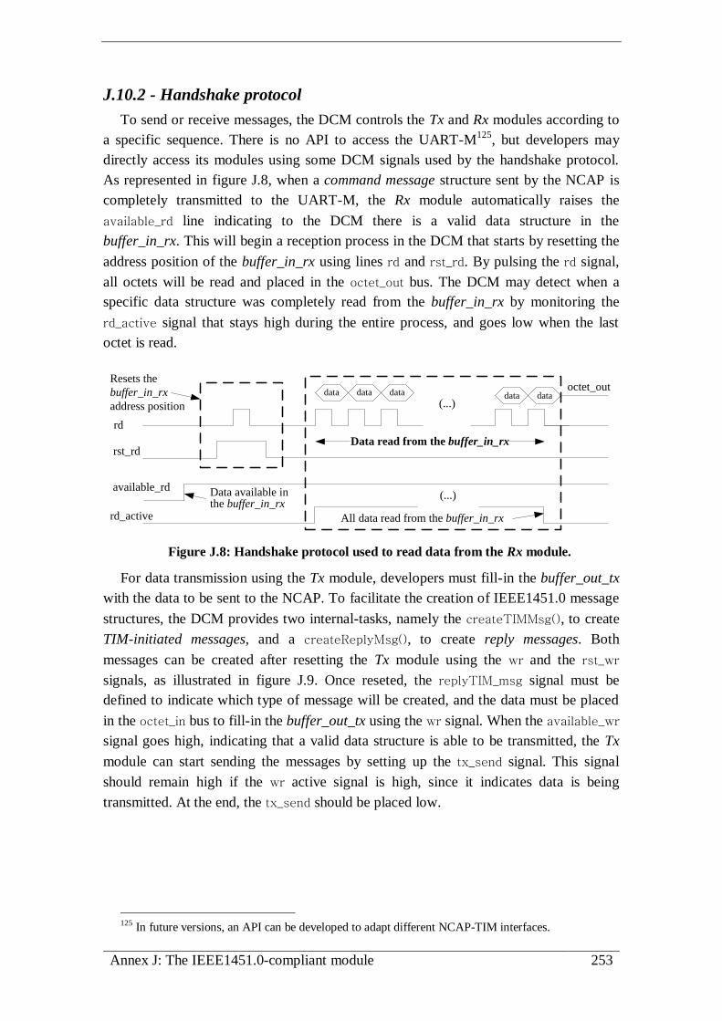
Annex J: The IEEE1451.0-compliant module 253
J.10.2 - Handshake protocol
To send or receive messages, the DCM controls the Tx and Rx modules according to
a specific sequence. There is no API to access the UART-M125
, but developers may
directly access its modules using some DCM signals used by the handshake protocol.
As represented in figure J.8, when a command message structure sent by the NCAP is
completely transmitted to the UART-M, the Rx module automatically raises the
available_rd line indicating to the DCM there is a valid data structure in the
buffer_in_rx. This will begin a reception process in the DCM that starts by resetting the
address position of the buffer_in_rx using lines rd and rst_rd. By pulsing the rd signal,
all octets will be read and placed in the octet_out bus. The DCM may detect when a
specific data structure was completely read from the buffer_in_rx by monitoring the
rd_active signal that stays high during the entire process, and goes low when the last
octet is read.
(...)
rd
rst_rd
available_rd Data available in the buffer_in_rx
rd_active All data read from the buffer_in_rx
Data read from the buffer_in_rx
(...)
data data data data dataoctet_out
Resets the
buffer_in_rx
address position
Figure J.8: Handshake protocol used to read data from the Rx module.
For data transmission using the Tx module, developers must fill-in the buffer_out_tx
with the data to be sent to the NCAP. To facilitate the creation of IEEE1451.0 message
structures, the DCM provides two internal-tasks, namely the createTIMMsg(), to create
TIM-initiated messages, and a createReplyMsg(), to create reply messages. Both
messages can be created after resetting the Tx module using the wr and the rst_wr
signals, as illustrated in figure J.9. Once reseted, the replyTIM_msg signal must be
defined to indicate which type of message will be created, and the data must be placed
in the octet_in bus to fill-in the buffer_out_tx using the wr signal. When the available_wr
signal goes high, indicating that a valid data structure is able to be transmitted, the Tx
module can start sending the messages by setting up the tx_send signal. This signal
should remain high if the wr active signal is high, since it indicates data is being
transmitted. At the end, the tx_send should be placed low.
125 In future versions, an API can be developed to adapt different NCAP-TIM interfaces.

254 An IEEE1451.0-compliant FPGA-based reconfigurable weblab
(...)wr
rst_wr
Resets the buffer_out_tx address position
available_WRData in the buffer_out_tx is ready to be transmitted
Reply or TIM-initiated messages
replyTIM_msg
tx_sendSends data through Tx
(...)wr_active
Fill-in the buffer_out_tx
All data transmitted
Data transmission
Uses the tasks:
createTIMMsg() or
createReplyMsg()
data data data (...)octet_in
Figure J.9: Handshake protocol used to fill-in the buffer_out_tx and to transmit data to
the NCAP.

Annex K: Weblab modules: specification and design 255
Annex K
Weblab modules: specification and design
K.1 - Definition of TC-tasks
The implementation of each TC-task requires the use of two variables to indicate to
the DCM that they finished their sequential operation, namely the end_tc_task and the
attending_event. The end_tc_task variable must be set to ‘1’ in all TC-tasks except in
the event() that should set the attending_event variable to ‘1’, as exemplified in the code
listed in table K.1.
Table K.1: Example of Verilog HDL code for implementing TC-tasks using the
mandatory end_tc_task and attending_event variables.
To all TC-tasks except for event() TC-tasks To event() TC-tasks task tc3_start;
begin
case(state_tc3)
0:begin rst_tc3<=0; en_tc3<=1;
access_tc3<=0; state_tc3<=1;
end
1:begin run_tc3<=1; state_tc3<=2; end
2:if(end_tc3) begin
run_tc3<=0; state_tc3<=0;
end_tc_task<=1;
end
end
endcase end
endtask
task es_event;
begin
case (state_evt)
(…)
8:begin if (wr_active_tx==0) begin
tx_send_tx<=0; state_evt<=0;
attending_event<=0;
end
end
endcase end
endtask
K.2 - Design of TEDSs and MTs
The data of each TEDS and MT is defined in an hexadecimal format. The TEDSs are
defined according to the structure specified in the IEEE1451.0 Std., and the MT must be
defined according to the description made in section 6.2.1. Both can be defined using an
hexadecimal editor, such as the XVI32126
for windows platforms illustrated in figure
K.1. The created file is a binary one able to be decoded by the Bind and Config software
modules adopted by the RecTool.
126 http://www.chmaas.handshake.de/delphi/freeware/xvi32/xvi32.htm

256 An IEEE1451.0-compliant FPGA-based reconfigurable weblab
Figure K.1: Freeware hexadecimal editor XVI32 used to define TEDSs and MTs.
K.3 - Examples of weblab modules
This annex presents four weblab modules compatible with the IEEE1451.0-Module
designed according to the description made in the section 6.3, namely: two digital I/O
modules, one controller for step-motors, and an event sensor. Their design followed the
sequence presented in section 6.3.4, which includes the specification of the required
inputs/outputs, associated TCs and sampling modes, the TEDSs and the TC-tasks to
interface them to the DCM. After binding these weblab modules to the IEEE1451.0-
Module, using the reconfiguration process described in section 6.4, they were validated
by issuing IEEE1451.0 commands using a PC connected to the TIM through the serial
communication tool named Comm Operator Pal127
.
K.3.1 - Digital I/O modules
Overview
Two simple weblab modules controlled by the IEEE1451.0-Module were developed
to control digital lines, namely an 8-Bit Input Module and a 6-Bit Output Module. Both
modules do not require the control of any specific parameter, since they just read and
write digital I/O signals. Due to their simplicity, each of them adopts a single TC for
controlling their I/Os. The behaviour of each TC was defined by the associated TC-
TEDSs, and implemented through TC-tasks, as conceptualized in figure K.2.
127 http://www.serialporttool.com/CommPalInfo.htm

Annex K: Weblab modules: specification and design 257
DS
Output
TC-tasks
TC-TEDS
IEEE1451.0-Module
TC6
6-Bit Output Module
Target
experiment
DS
Input
TC-tasks
TC-TEDS
IEEE1451.0-Module
TC8
8-Bit Input Module
Target
experiment
Figure K.2: Digital I/Os weblab modules connected to the IEEE1451.0-Module.
Internal modules
Both weblab modules are implemented through single HDL modules integrating DSs
with 1 register length each. They are accessed by independent TCs controlled according
to the definition made in TC-TEDSs and using an handshake protocol implemented by
the TC-tasks and by the HDL modules. This protocol is synchronized by the same clk
signal adopted for the IEEE1451.0-Module, and includes the management of two lines,
namely the run and end lines, to access data available in the in and out buses, as
represented in figure K.3. The rst and en lines reset and enable each weblab module.
TC
data
run
end
out
data
run
end
in
Output
data is available in the data_out bus
Input
data read is available in the out bus
enclk
rstin
runend
6-Bit Output Module(output_6bits.v)
en_tcrst_tcout_tcrun_tcend_tc
6
DCM
IEEE1451.0-Module
clk_tc data_out
DS
6
enclk
rstoutrunend
8
data_in
DS
8en_tcrst_tcin_tc
run_tcend_tc
clk_tc
DCM 8-Bit Input Module(Input_8bits.v)TC
Figure K.3: Buses, lines and the handshake protocol of the I/O weblab modules.
The DCM controls the TCs according to definitions made in the fields of the TC-
TEDSs, both read-only, as defined in their attributes. Although more fields have been
defined, table K.2 and table K.3 present the most relevant defined in each TC-TEDS.
Table K.2: TC-TEDS relevant fields defined to control the 8-Bit Input Module.
Field num. Description Data Type octets Value (hex)
- TEDS length UInt32 4 00.00.00.5D
0-2 Reserved - - -
3 TEDS identification: (Family=00h, Class =03h, Version =01h, T. Length=01h)
UInt8 4 03.04.
00.03.01.01
11 Channel Type set to sensor (=0) UInt8 1 0B.01.00
12 Physical units set to digital (=4) UInt8 3 0C.03.
32.01.04

258 An IEEE1451.0-compliant FPGA-based reconfigurable weblab
18
Sample information (data model, length and
significant bits). DataModel (field=28h, UInt8, Bit Sequence=04h); Length
(field=29h, UInt8, ModLenth=01h); Model significant bits
(field=2Ah; UInt16, SigBits=00.08h)
UInt8+
UInt8 +
UInt16
10
12.0A.
28.01.04.
29.01.01.
2A.02.00.08
19
DS definition (only the maximum data
repetition field is specified, which represents
the DS length). (field=2Bh, UInt16, Max. data
rep.=00.01h)
UInt16 4 13.04. 2B.02.00.01
31 Sampling mode capability: (field=30h, UInt8, immediate sampling capability=10h)
UInt8 3 1F.03. 30.01.10
…
- Checksum UInt16 2 F6.24
Table K.3: TC-TEDS relevant fields defined to control the 6-Bit Output Module.
Field num. Description Data Type octets Value (hex)
- TEDS length UInt32 4 00.00.00.5D
0-2 Reserved - - -
3 TEDS identification: (Family=00h, Class =03h, Version =01h, T. Length=01h)
UInt8 4 03.04.
00.03.01.01
11 Channel Type set to actuator (=1) UInt8 1 0B.01.01
12 Physical units set to digital (=4) UInt8 3 0C.03. 32.01.04
18
Sample information (data model, length and
significant bits). DataModel (field=28h, UInt8, Bit Sequence=04h); Length
(field=29h, UInt8, ModLenth=01h); Model significant bits
(field=2Ah; UInt16, SigBits=00.06h)
UInt8+
UInt8 +
UInt16
10
12.0A.
28.01.04.
29.01.01.
2A.02.00.06
19
DS definition (only the maximum data
repetition field is specified, which represents
the DS length) (field=2Bh, UInt16, Max. data
rep.=01h)
UInt16 4 13.04. 2B.02.00.01
31 Sampling mode capability: (field=30h, UInt8, immediate sampling capability=10h)
UInt8 3 1F.03. 30.01.10
…
- Checksum UInt16 2 F6.25
For the 8-Bit Input Module, the adopted TC was defined as a sensor able to read 8
digital signals. For the 6-Bit Output Module the adopted TC was defined as an actuator
able to write 6 digital signals. Both are accessed using an immediate sampling mode,
which means that Read/WriteTCDSsegment commands automatically access the rd() and
wr() TC-tasks. Furthermore, for each TC was defined the required TC-tasks init() and
update().
Validation
For validating the weblab modules, physical connections between their I/O lines
were established, and IEEE1451.0 commands were issued. As exemplified by the
diagram of figure K.4, only the ReadTEDSsegment command was issued to get
information about the TIM and about the current states of the TCs. Latter, both weblab
modules were placed on the operating state using the TCOperation command, preceding
the read/write operations. To the 8-Bit Input Module, only the ReadTCDSsegment
command was issued to get the current state of its inputs, since TCs defined as sensors

Annex K: Weblab modules: specification and design 259
cannot receive WriteTCDSsegment commands, unlike the 6-Bit Output Module where
both commands were issued. These commands were issued several times to evaluate if
the weblab modules were running correctly, as exemplified in figure K.5.
Reads the
META-TEDS
and both
TC-TEDSs
Write data to the
DS of the 6-Bit
Output Module
Reads DSs
from boths
modules
Set both TCs to
the operating
state
init end
Figure K.4: Sequence of commands issued to the I/O digital weblab modules.
reads TC-TEDS 8-Bit Input Module(ReadTEDSsegment)
Set 8-Bit Input Module to operate(TCoperate)
Writes the Input module(ReadTCDSsegment)
reads TC-TEDS 6-Bit Output module(ReadTEDSsegment)
reads META-TEDS (ReadTEDSsegment)
Writes 5 to the Output module(WriteTCDSsegment)Reads 5 from the
Output module(ReadTCDSsegment)
Reads the Input module(ReadTCDSsegment)
error reply
Figure K.5: Commands issued to validate the I/O digital weblab modules.

260 An IEEE1451.0-compliant FPGA-based reconfigurable weblab
K.3.2 - Step-Motor Controller Module (SMCM)
Overview
Although the Step-Motor Controller Module (SMCM) provides several control
parameters, such as the number of steps, direction, etc., the main output is a sequence of
6 digital output signals for energizing the inductors of any bipolar step-motor interfaced
by a power bridge to adapt the outputs of the FPGA-based board to the inputs of the
step motor. To simplify the implementation and reduce the required FPGA’s resources,
and taking into consideration that the outputs are a digital sequence of signals whose
units are not relevant, a single TC was adopted. The SMCM is controlled by the
reception of a trigger signal to start and stop the generation of a digital output sequence,
whose samplings are provided by an internal DS controlled according to definitions of
TEDSs’ fields. Those fields are provided by a TC-TEDS, and by a MD-TEDS. The TC-
TEDS specifies the TC as an actuator with 6 outputs running in a continuous sampling
mode with the DS operating in the recirculation mode. The MD-TEDS specifies all
parameters to control, namely the direction, step modes, speed, and if the control is
remotely or locally made using a push button available in the FPGA-based board. All
these fields are writable and readable by the standard IEEE1451.0 commands
Read/WriteTEDSsegment and by the internal DCM, so it can control the TC using
specific TC-tasks to start/stop the step-motor. Figure K.6 provides a generic overview
of the SMCM blocks.
DS
SMCM
TC-tasks
TC-TEDS
MD-TEDS
IEEE1451.0-Module
trigger
push-buttonpowerdriver
bipolarstep
motorrecirculation
mode control type
(remotly/local)
TC 6
Figure K.6: SMCM connected to the IEEE1451.0-Module.
Internal modules
The SMCM comprises a set of HDL modules and TC-tasks for controlling the
adopted TC according to three TEDS: i) Meta-TEDS; ii) TC-TEDS and; iii) a MD-
TEDS. The Meta-TEDS defines the whole TIM structure, while the behaviour and the
features of the SMCM are defined by a MD-TEDS, and by a read-only TC-TEDS.
Table K.4 lists the most relevant fields of the TC-TEDS. Additional parameters were
defined in the MD-TEDS presented in table K.5, such as the direction, number and step
modes, a time divider to control the speed of a step-motor, plus the type of control that
can be made using IEEE1451.0 commands or using a push button in the FPGA-based-
board. All the MD-TEDS fields can be updated through the WriteTEDSsegment
command and read by the ReadTEDSsegment command to control/monitor the
behaviour of the entire SMCM.

Annex K: Weblab modules: specification and design 261
Table K.4: TC-TEDS relevant fields defined to control the SMCM.
Field num. Description Data Type octets Value (hex)
- TEDS length UInt32 4 00.00.00.60
0-2 Reserved - - -
3 TEDS identification (Family=00h, Class =03h,
Version =01h, T. Length=01h) UInt8 4
03.04
00.03.01.01
11 Channel type set to actuator (=1) UInt8 1 0B.01.01
12 Physical units set to digital (=4). UInt8 3 0C.03. 32.01.04
18
Sample information: data model, length and
significant bits. DataModel (field=28h, UInt8, Bit Sequence=04h); Length
(field=29h, UInt8, ModLength=01h); Model significant
bits (field=2Ah; UInt16, SigBits=00.06h)
UInt8+
UInt8 +
UInt16
10
12.0A.
28.01.04
29.01.01
2A.02.00.06
19
DS definition (only the maximum data
repetition field is specified, which represents
the DS length) (field=2Bh, UInt16, Max. data
rep.=08h)
UInt16 4 13.04.
2B.02.00.08
31 Sampling mode capability: (field=30h, UInt8, continuous mode capability=08h)
UInt8 3 1F.03 30.01.08
33 End-of-data-set operation attribute: (field=21h, UInt8, recirculation mode=04h)
UInt8 3 21.01.04
…
- Checksum UInt16 2 F5.FD
Table K.5: MD-TEDS defined fields to control the SMCM.
Field num. Description Data Type octets Value (hex)
- TEDS length UInt32 4 00.00.00.1A
0-2 Reserved - - -
3 TEDS identification: (Family=00h, Class =80h,
Version =01h, T. Length=01h) UInt8 4
03.04
00.80.01.01
4 Direction. Indicates the direction of the step-
motor rotation: left (=0) or write(=1) UInt8 1 04.01.01
5
Number of steps. Indicates the number of steps
the motor will do after receiving a trigger
signal. If the value is set to its maximum
(FF.FF hex) this field becomes irrelevant and the step sequences are generated continuously.
UInt8 2 05.02.FF.FF
6 Step mode. Defined according to three modes: half step (=0); normal drive(=1) or wave drive(=2)
UInt8 1 06.01.00
7
Step speed (steps/s). Defines the internal clock
rate of the module, and therefore the speed of
the generated step-motor sequences according
to the equation:
speedReg =(clk_external/2) / (Step speed)
Currently: clk_external =19200 bps
UInt8 3 07.03.
00.09.60
8
Control type. Specifies the type of control: remotely using IEEE1451.0 commands (=0) or locally
using a push button at a transition level (=1) or at a state
level (=2).
UInt8 1 08.01.00
- Checksum UInt16 2 FC.CF
Although several protocols could be used to control the TC, the adopted is similar to
the one used for accessing the TEDS-M and the SSM described in the previous annex J.
As represented in figure K.7, it uses the lines run and end to issue a particular code and,

262 An IEEE1451.0-compliant FPGA-based reconfigurable weblab
for some of them, the data to specify the behaviour of the SMCM by changing its
internal parameters. The code is defined using the access bus, and the data is defined by
the out bus, as detailed in table K.6. Each code changes the behaviour of the SMCM
according to a value read from the MD-TEDS placed in the in bus to define the number
of steps and the speed parameters, both representing the use of more than one octet and,
therefore, more than one code. For these parameters, the code also specifies both the
parameter and the octet number, starting from the most to the less significant octet.
run
end
out_tc
code/data issued
issue a code/data
clkDCM /
TC-tasks SMCM
run
end
out_tc
access_tcaccess_tc
out_tc
access_tc
Figure K.7: Handshake protocol used to access the SMCM through the TC-tasks.
Table K.6: Internal SMCM access codes.
code
(access bus) Meaning
0 Starts generating the step sequences (trigger command).
1 Stops generating the step sequences (trigger command).
2 Defines the direction: write (=1) or left (=0).
3 Defines the number of steps to generate (access=3 means the most significant octet
and access=4 means the less significant octet). 4
5 Defines the step mode: half step (=0); normal drive (=1) or; wave drive (=2).
6 These 3 octets correspond to the speedReg that defines the speed of each step in the
motor. The clk_external is an input signal on the SMCM.
speedReg =(clk_external/2) / (Step speed)
7
8
9 Defines the way the SMCM starts generating the step sequence: commands (=0);
external button at transition (=1) or; external button at state (=2).
The SMCM adopted a trigger dependent sampling mode, i.e. the continuous
sampling mode. The start() and stop() TC-tasks start and stop the generation of the step
sequences, and the init() and update() TC-tasks update the way the SMCM is initialized
and runs. The access to those TC-tasks is made internally by the DCM when the
TriggerCommand, the AbortTrigger and the Reset commands are issued, according to
the definitions made in subsection 6.3.3.
The SMCM is controlled by instructions received from the IEEE1451.0-Module. It
comprises four internal modules interfaced through a set of buses and lines, as
illustrated in figure K.8. They are all described in Verilog HDL and each one has
specific features described in table K.7.

Annex K: Weblab modules: specification and design 263
en
clk
rst
in
run
end
access
error
direction_mpp1
steps_mpp1
mode_mpp1
speed_mpp1
run_crt button_crt
direction
steps
mode
run_crt button_crt
2
clk
time_devider
run
run_button
16
2
24
clk_in
clk_out
clk
en
data_
outDS
clk_external
6
mpp2.v mpp1.v
mpp_button_controller.v mpp_clk_generator.v
en_tc3
rst_tc3
out_tc3
run_tc3
end_tc3
access_tc3
error_tc3
8
4
DCM
button
push-button
IEEE1451.0-Module
powerdriver
bipolarstep
motor
Step-Motor Controller Module (SMCM)
clk
rdy_mpp1
run_mpp1
a
a
Figure K.8: The SCMC HDL modules and buses.
Table K.7: Internal modules of the SMCM and their features.
Internal module Operation
mpp2.v
Is the decoder and controller of the SMCM and it is connected to the IEEE1451.0-
Module. It decodes the code defined in the access bus and updates the other
modules.
mpp1.v
According to the values defined in the buses provided by the mpp2.v module, if
the run signal, provided by the mpp_button_controller.v module, is set, it starts by
generating the digital sequence for controlling a step-motor. This sequence is
generated at a rate defined in the clk signal provided by the mpp_clk_generator.v
module.
mpp_button_
controller.v
This module implements the control type for the SMCM i.e., if the step sequence
generated by the mpp1.v module starts when a trigger is generated by an
IEEE145.0 command or when the FPGA button is pressed (either using transition
or state operation levels).
mpp_clk_
generator.v
Specifies the rate at which the step sequences are generated, according to the
value defined for the time_divider bus.
Validation
To validate the SMCM, a set of IEEE1451.0 commands were issued from a PC to the
IEEE1451.0-Module using the Comm Operator Pal serial port tool. As represented in
figure K.9, the commands change and monitor the fields defined in the MD-TEDS and
trigger the SMCM to start and stop its operation.

264 An IEEE1451.0-compliant FPGA-based reconfigurable weblab
Read
MD-TEDS
Write MD-TEDSUpdate MD-
TEDS
Set TC to the
operating stateTrigger
Valid ?
no
yes
Stop trigger
Read MD-
TEDS
init
Read MD-TEDS
end
Test the rotation of the step-motor using the button on
the FPGA-based board
Figure K.9: Sequence of commands adopted for validating the SMCM.
At the beginning some or all MD-TEDS fields are read and the adopted TC is set to
the operating state, so TriggerCommand and AbortTrigger commands may be issued to
start or stop the SMCM operation. Based on the read fields, these are changed using the
WriteTEDSsegment command, creating a temporary TEDS, to be latter validated using
the UpdateTEDS command. If no error is generated, the command validates the
temporary TEDS and all its fields are copied into the new MD-TEDS, otherwise there is
no change, and users should verify which fields turned the MD-TEDS invalid. During
this process the ReadTEDSsegment command can be issued just to verify the contents of
the MD-TEDS.
According to the described sequence and using the TC number 3, figure K.10
exemplifies some commands issued and the replies generated by the IEEE1451.0-
Module during the validation. It starts by issuing the readTEDSsegment command
retrieving the contents of the current MD-TEDS. To start/stop the rotation of the step-
motor the triggerCommand and stopTrigger commands were applied, both retrieving
successful replies, meaning the correct operation of the step-motor. Latter, the contents
of the MD-TEDS were changed defining the type of control from remote to local using
the external button at transition level (field 8 of the MD-TEDS was changed from 0 to
1). This operation was processed using the writeTEDSsegment and the updateTEDS
commands to validate the new MD-TEDS. Since the reply from the updateTEDS
indicated that the MD-TEDS was correctly defined, the readTEDSsegment was issued
to read the new MD-TEDS. The step-motor control was then verified by using the
associated button on the FPGA-based board. Latter, and just for verification purposes, a
wrongly defined command message was issued to the infrastructure, and an error reply
message was retrieved, which could have been evaluated by reading the event register
of the associated TC.

Annex K: Weblab modules: specification and design 265
Reads MD-TEDS (ReadTEDSsegment)
Sets SMCM to operate(TCoperate)
Sends a trigger to rotate the step-motor (triggerCommand)
Sends a trigger to stop the rotation of the step-motor (stopTrigger)
Writes a new MD-TEDS to change the SMCM operation type to button
transition (WriteTEDSsegment)Validates the MD-TEDS (updateTEDS)
Reads MD-TEDS (ReadTEDSsegment)Example of an error
command
Figure K.10: IEEE1451.0 commands issued to validate the SMCM.
K.3.3 - Event sensor
Overview
For validating the event mechanism implemented by the IEEE1451.0-Module and
described in section 6.2.1, a weblab module named Event Sensor (ES) was designed.
This ES basically monitors a specific input line that, when raised, generates an event
that triggers the IEEE1451.0-Module to send a dummy TIM-initiated message to the
NCAP. Figure K.11 illustrates the connections of the ES to the IEEE1451.0-Module,
presenting an event line, belonging to the adopted TC, to trigger the event() TC-task
that sends the TIM-initiated message to the NCAP.
ESTC-TEDS
event() task
IEEE1451.0-Module event line
external
event
TIM-initiated message
UART-M
TCNCAP
TIM
Figure K.11: Event Sensor connected to the IEEE1451.0-Module.
Internal modules and validation
A single HDL module implements the ES. When it detects an external event it raises
the event line indicating to the IEEE1451.0-Module that an event was generated in the
associated TC, whose relevant fields are listed in table K.8.

266 An IEEE1451.0-compliant FPGA-based reconfigurable weblab
Table K.8: Defined TC-TEDS relevant fields to control the event sensor.
Field num. Description Data Type octets Value (hex)
- TEDS length UInt32 4 00.00.00.5D
0-2 Reserved - - -
3 TEDS identification: (Family=00h, Class =03h,
Version =01h, T. Length=01h) UInt8 4
03.04
00.03.01.01
11 Channel type set to event sensor (=2) UInt8 1 0A.01.02
12 Physical units set to digital (=4) UInt8 3 0C.03. 32.01.04
18
Sample information: data model, length and
significant bits. DataModel (field=28h, UInt8, Bit Sequence=04h); Length
(field=29h, UInt8, ModLength=01h); Model significant
bits (field=2Ah; UInt16, SigBits=00.01h)
UInt8+
UInt8 +
UInt16
10
12.0A.
28.01.04
29.01.01
2A.02.00.01
19
DS definition (only the maximum data
repetition field is specified, which represents
the DS length) (field=2Bh, UInt16, Max. data
rep.=01h)
UInt16 4 13.04.
2B.02.00.01
31 Sampling mode capability: (field=30h, UInt8, free-running without pre-
trigger=04h) UInt8 3
1F.03
30.01.04
…
- Checksum UInt16 2 F6.35
The adopted TC was defined as an event sensor that monitors one digital signal
according to a free-running sampling mode that does not require any pre-trigger to start
its operation. This means that the TC is constantly monitoring events and providing that
information to the IEEE1451.0-Module, so it may generate a TIM-initiated message.
Figure K.12 illustrates a simple validation using this ES when an event was detected
and reported by the TC, creating a dummy TIM-initiated message.
Figure K.12: TIM-initiated message retrieved from the ES after detecting an event.

Annex L: Reconfiguration 267
Annex L
Reconfiguration
L.1 - Examples of report files created during the
reconfiguration process
This annex presents examples of files created during the reconfiguration process,
namely:
reports generated in the build operation using the Bind software module
(Bbind_2013-03-05_15:07:30.rep in table L.1) and the Config software module
(Bteds_2013-03-05_15:07:30.rep in table L.2);
the report generated after the synthesis operation (Syn_2013-03-
05_15:08:17.rep in table L.3) that is the output of the ISE Webpack synthesis
indicating the successful creation of the bitstream file (*.bit);
the report generated in the configuration of the TIM that involves the creation of
the SVF file from the bitstream file (svf_2013-03-05_15:27:06.rep in table L.4),
which is made by the iMPACT tool, and;
the report generated by the UrJTAG module indicating the configuration of the
FPGA (Reconf_2013-10-14_15:58:36.rep in table L.5).
Table L.1: Report generated by the Bind software module.
Bbind_2013-03-05_15:07:30.rep
*****************************************************************
Configuration file used to bind transducers/weblab instruments
into the IEEE1451-infrastructure.
Developed by Ricardo Costa @ November 2011.
For further information or error report
please use the email: [email protected]
*****************************************************************
**General interface files:
> <declarations> created.
> <directions> created.
> <declarations_dcmim> created.
> <directions_dcmim> created.
> <interface_dcmim> created.
> <initial> created.
> <wires> created.
> <tc_controller_interface> created.
> <tc_declarations> created.
> <tc_directions> created.
> <tc_interface> created.
> <tc_task_location> created.
**Transducers tasks files:
> <tc_start> created.
> <tc_stop> created.

268 An IEEE1451.0-compliant FPGA-based reconfigurable weblab
> <tc_rd> created.
> <tc_wr> created.
> <tc_init> created.
> <tc_update> created.
> *WARNING: No <tc_event> created.
> *WARNING: No tc_event_connections created.
**Generic Parameters:
> <num_tcs> correctly created.
> <mem_buffer> correctly created.
> <bps_uart> correctly created.
> <im_errors> correctly created.
> <im_events> correctly created.
Table L.2: Report generated by the Config software module.
Bteds_2013-03-05_15:07:30.rep
*****************************************************************
This program checks and creates verilog files according to
the IEEE1451.0 infrastructure.
Developed by Ricardo Costa @ November 2011.
For further information or error report
please use the email: [email protected]
*****************************************************************
> TEDS files contents are correctly defined.
> Memory Verilog TEDS files correctly defined.
> TEDS controller was correctly defined.
> MAP_Table verilog file correctly defined.
> TEDS parameters correctly defined.
> Map Table parameters correctly defined.
> TEDS connections created.
> TEDS instances correctly created.
> Status memory correctly created.
> State memory correctly created.
Table L.3: Report generated by the ISE Webpack in the synthesis operation.
Syn_2013-03-05_15:08:17.rep
Changed current working directory to the project directory:
"/home/labserver/www/labserver/programTIM/user_00/ise_project"
Reloading the project.
Finished reloading the project.
Started : "Synthesize - XST".
Running xst...
Command Line: xst -intstyle ise -ifn
"/home/labserver/www/labserver/programTIM/user_00/ise_project/TIM_main.xst" -ofn
"/home/labserver/www/labserver/programTIM/user_00/ise_project/TIM_main.syr"
Reading design: TIM_main.prj
=========================================================================
* HDL Compilation *
=========================================================================
Compiling verilog file "../../TIM/ieee1451_infrastructure/user_configurations/Output_6bits_main.v" in library
work
Compiling verilog file "../../TIM/ieee1451_infrastructure/user_configurations/Input_8bits_main.v" in library
work
Module <Output_6bits_main> compiled
Compiling verilog file "../../TIM/ieee1451_infrastructure/TEDS_Controller/memory_7.v" in library work
Compiling verilog include file "../../TIM/ieee1451_infrastructure/Controller/../definitions.vh"
(…)
Module <main_Controller> compiled
Compiling verilog include file "../../TIM/ieee1451_infrastructure/Controller/../Transducers/declarations.vh"
Compiling verilog include file "../../TIM/ieee1451_infrastructure/Controller/../Transducers/directions.vh"
Compiling verilog include file
"../../TIM/ieee1451_infrastructure/Controller/../Transducers/interface_dcmim.vh"

Annex L: Reconfiguration 269
Module <TIM_main> compiled
No errors in compilation
Analysis of file <"TIM_main.prj"> succeeded.
(…)
=========================================================================
* Design Hierarchy Analysis *
=========================================================================
Analyzing hierarchy for module <TIM_main> in library <work>.
(…)
Analyzing module <memory_0> in library <work>.
Module <memory_0> is correct for synthesis.
(…)
=========================================================================
* HDL Analysis *
=========================================================================
Analyzing top module <TIM_main>.
Module <TIM_main> is correct for synthesis.
(…)
=========================================================================
* HDL Synthesis *
=========================================================================
Performing bidirectional port resolution...
INFO:Xst:2679 - Register <TC_lut_states<0>> in unit <Status_state_controller> has a constant value of 011
during circuit operation. The register is replaced by logic.
(…)
=========================================================================
HDL Synthesis Report
Macro Statistics
# RAMs : 12
100x8-bit single-port RAM : 1
109x8-bit single-port RAM : 3
(…)
Analysis completed Tue Mar 5 15:22:22 2013
--------------------------------------------------------------------------------
Generating Report ...
Number of warnings: 0
Total time: 8 secs
Process "Generate Post-Place & Route Static Timing" completed successfully
Started : "Generate Programming File".
Running bitgen...
Command Line: bitgen -intstyle ise -f TIM_main.ut TIM_main.ncd
Process "Generate Programming File" completed successfully
Table L.4: Report generated in the reconfiguration operation using the iMPACT tool.
svf_2013-03-05_15:27:06.rep
Release 13.3 - iMPACT O.76xd (lin)
Copyright (c) 1995-2011 Xilinx, Inc. All rights reserved.
Preference Table
Name Setting
StartupClock Auto_Correction
AutoSignature False
(…)
svfUseTime false
SpiByteSwap Auto_Correction
AutoInfer false
SvfPlayDisplayComments false
'1': Loading file
'/home/labserver/www/labserver/programTIM/user_00/list_reconf_files/2013-03-05_1
5:08:17.bit' ...
done.
UserID read from the bitstream file = 0xFFFFFFFF.
----------------------------------------------------------------------
----------------------------------------------------------------------
'1': Programming device...
LCK_cycle = NoWait.

270 An IEEE1451.0-compliant FPGA-based reconfigurable weblab
LCK cycle: NoWait
done.
LCK_cycle = NoWait.
LCK cycle: NoWait
'1': Programmed successfully.
Elapsed time = 1 sec.
Table L.5: Report generated by the UrJTAG tool after sending the weblab project to the
FPGA-based board.
Reconf_2013-10-14_15:58:36.rep
Connected to libftdi driver.
IR length: 30
Chain length: 4
Device Id: 00000110111001011110000010010011 (0x0000000006E5E093)
Manufacturer: Xilinx
Part(0): XC2C64-VQ44
Stepping: 0
Filename: /usr/local/share/urjtag/xilinx/xc2c64a-vq44/xc2c64a-vq44
(…)
Device Id: 00100001110000111010000010010011 (0x0000000021C3A093)
Manufacturer: Xilinx
Part(3): xc3s1600e_fg320
Stepping: 2
Filename: /usr/local/share/urjtag/xilinx/xc3s1600e_fg320/xc3s1600e_fg320
Warning: USB-Blaster frequency is fixed to 12000000 Hz
L.2 - Example of a configuration file
This annex presents some parts of a configuration file (*.conf), listed in table L.6, for
building the weblab project. For better comprehension, it is commented and should be
analysed in conjunction with the schematics presented in figure L.1 of the annex L.3.
Table L.6: Example of a configuration file used in the reconfiguration process.
*.conf
(…)
########################################################################
# 1.1- Check TEDS configurations #
########################################################################
<teds_check>
#
# IEEE1451TEDS
Meta_TEDS.teds
XdrcName_TEDS.teds
# input8bits
#TC1
Input_8bits_TC_Channel.teds
(…)
</ teds_check>
########################################################################
# 1.2- Generate verilog HDL TEDS files. #
########################################################################
(…)
<teds_generate>
#
# IEEE1451 TEDS
Meta_TEDS.teds,memory_0.v,0,1,0,Meta_TEDS_for_validation_1
XdrcName_TEDS.teds,memory_1.v,1,1,0,XdrcNameTEDS_"TIM"_for_validation_1
# input8bits
#TC1

Annex L: Reconfiguration 271
Input_8bits_TC_Channel.teds,memory_2.v,2,1,0,TC_TEDS_input8bits(TC1)
(…)
</teds_generate>
(…)
########################################################################
# 1.3- checks Map Table and creates a verilog file for TEDScode x memories association. #
########################################################################
<map_table>
map_table_val_1.map
</map_table>
########################################################################
# 1.4- Defines sequentially the mask registers for each TC (std. 1451 status registers) #
########################################################################
<status_generate>
# TIM
'hffffffff,TIM
# input8bits
#TC1
'hffffffff,input8bits(TC1)
(…)
</status_generate>
###############################################################################
# PART 2: #
# Configuration file to bind weblab modules to the IEEE1451.0-Module #
###############################################################################
########################################################################
# 2.1- External connections (Target Experiment /External signals <-> IEEE1451.0-Module) #
########################################################################
<declarations>
# input8bits
data_in_tc1,
(…)
</declarations>
<directions>
# input8bits
input [7:0] data_in_tc1;
(…)
</directions>
########################################################################
# 2.2- Internal connections (IEEE1451.0-Module <-> DCM) #
########################################################################
<declarations_dcmim>
# input8bits
data_in_tc1,
(…)
</declarations_dcmim>
<directions_dcmim>
# input8bits
input [7:0] data_in_tc1;
(…)
</directions_dcmim>
<interface_dcmim>
# input8bits
.data_in_tc1(data_in_tc1),
(…)
</interface_dcmim>
########################################################################
# 2.3- Tasks variables initializations. #
########################################################################
<initial>
# TC1 - input8bits(TC1)
state_tc1<=0;
(…)
</initial>

272 An IEEE1451.0-compliant FPGA-based reconfigurable weblab
########################################################################
# 2.4- DCM internal wires. #
########################################################################
<wires>
# input8bits
#TC1
wire en_tc1;
wire rst_tc1;
wire [7:0] in_tc1;
wire run_tc1;
wire end_tc1;
#
#External Wires
wire [7:0] data_in_tc1;
#
(…)
</wires>
########################################################################
# 2.5 - DCM internal wire connections (DCM controller <-> DCM internal wires) #
########################################################################
<tc_controller_interface>
# input8bits
#TC1
.en_tc1(en_tc1),
.rst_tc1(rst_tc1),
.in_tc1(in_tc1),
.run_tc1(run_tc1),
.end_tc1(end_tc1),
(…)
</tc_controller_interface>
<tc_declarations>
# input8bits
#TC1
en_tc1,
rst_tc1,
in_tc1,
run_tc1,
end_tc1,
(…)
</tc_declarations>
<tc_directions>
# input8bits
#TC1
output en_tc1; reg en_tc1;
output rst_tc1; reg rst_tc1;
input [7:0] in_tc1;
output run_tc1; reg run_tc1;
input end_tc1;
(…)
</tc_directions>
########################################################################
# 2.6- Weblab modules internal wire connections. #
########################################################################
<tc_interface>
# input8bits
Input_8bits_main IM_Input_8bits (
#CLK
.clk(clk),
#TC1
.en(en_tc1),
.rst(rst_tc1),
.out(in_tc1),
.run(run_tc1),
.end_(end_tc1),
#
#External Wires
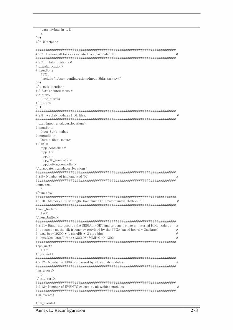
Annex L: Reconfiguration 273
.data_in(data_in_tc1)
);
(…)
</tc_interface>
########################################################################
# 2.7- Defines all tasks associated to a particular TC. #
########################################################################
# 2.7.1- File locations.#
<tc_task_location>
# input8bits
#TC1
`include "../user_configurations/Input_8bits_tasks.vh"
(…)
</tc_task_location>
# 2.7.2- adopted tasks.#
<tc_start>
3:tc3_start();
</tc_start>
(…)
########################################################################
# 2.8- weblab modules HDL files. #
########################################################################
<tc_update_transducer_locations>
# input8bits
Input_8bits_main.v
# output6bits
Output_6bits_main.v
# SMCM
mpp_controller.v
mpp_1.v
mpp_2.v
mpp_clk_generator.v
mpp_button_controller.v
</tc_update_transducer_locations>
########################################################################
# 2.9- Number of implemented TC #
########################################################################
<num_tcs>
3
</num_tcs>
########################################################################
# 2.10- Memory Buffer length. (minimum=12) (maximum=2^16=65536) #
########################################################################
<mem_buffer>
1200
</mem_buffer>
########################################################################
# 2.11- Baud rate used by the SERIAL PORT and to synchronize all internal HDL modules #
#(it depends on the clk frequency provided by the FPGA based board - Oscilator) #
# e.g.: bps=19200 + 1 startBit + 2 stop bits #
# bps:(Oscilator/2)/bps (1302,08-50MHz) -> 1302 #
########################################################################
<bps_uart>
1302
</bps_uart>
########################################################################
# 2.12- Number of ERRORS caused by all weblab modules #
########################################################################
<im_errors>
0
</im_errors>
########################################################################
# 2.13- Number of EVENTS caused by all weblab modules #
########################################################################
<im_events>
0
</im_events>
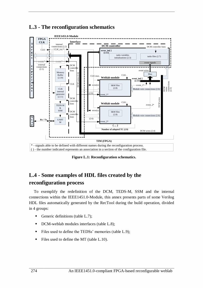
274 An IEEE1451.0-compliant FPGA-based reconfigurable weblab
L.3 - The reconfiguration schematics
IEEE1451.0-Module
Interface
DCM controller
Weblab module
( ... )
DC
M w
ires
(2
.4)
CLK_ext.*
CLK max.
event signals
event_1*
event_2*
Module wire connections (2.6)
Module wire connections (2.6)
DC
M w
ires
DC
M
wir
esco
nn
ecti
on
s(2
.5)
error(s)
error(s)
internal connections (2.2)
error_im[ ] (2.12)
external connections
(2.1)
I&M files
(2.8)
tasks variables
initializations (2.3)tasks files (2.7)
Number of adopted TC (2.9)
Memory
Buffer
(2.10)
CLK
internal
generator
(2.11)
CLK
CLK
CLK
TEDS-M
&
SSM
UART
M
Rx / Tx
N
C
A
P
Target
experiment
FPGA
CLK
CLK
TIM (FPGA)
DCM
controller
lines
DCM
controller
lines
DCM
controller
lines
DCM controller lines
event wires
event_im[ ](2.13)
Mux
events* events*
event_1*
event_2*
DCM wires (2.4)
I&M files
(2.8)
(2.6)
(2.6)
* - signals able to be defined with different names during the reconfiguration process.
( ) - the number indicated represents an association in a section of the configuration file.
Weblab module
Figure L.1: Reconfiguration schematics.
L.4 - Some examples of HDL files created by the
reconfiguration process
To exemplify the redefinition of the DCM, TEDS-M, SSM and the internal
connections within the IEEE1451.0-Module, this annex presents parts of some Verilog
HDL files automatically generated by the RecTool during the build operation, divided
in 4 groups:
Generic definitions (table L.7);
DCM-weblab modules interfaces (table L.8);
Files used to define the TEDSs’ memories (table L.9);
Files used to define the MT (table L.10).

Annex L: Reconfiguration 275
Table L.7: Example of Verilog HDL files with generic definitions.
directions.vh (defines directions of the I/O on the FPGA-based board) //////////////////////////////////////////////////////////////////////////
//File automatically created.
//Created on: Mon Feb 04 18:54:34 2013
//////////////////////////////////////////////////////////////////////////
output [5:0] data_out_tc1;
input [7:0] data_in_tc2;
output [5:0] data_out_tc3; (…)
definitions_GENERIC.vh (generic parameters)
//////////////////////////////////////////////////////////////////////////
//File automatically created.
//Created on: Mon Feb 04 18:54:34 2013
//////////////////////////////////////////////////////////////////////////
`define TC_number 3
`define bits_pointer_TC_number 4 //>=(log[2](TC_number+1)*3)
`define bits_pointer_TC_number_small 3 //>=(log[2](TC_number+1)*2)
`define bits_pointer_TC_number_tiny 2 //>=(log[2](TC_number)
`define max_mem_buffer 100
`define bits_max_mem_buffer 7 //>=(log[2])
`define bps_divisor 1302
`define bps_length_counter 11 //>=(log[2])
`define error_num_im 0
`define event_num_im 0
Table L.8: Example of Verilog HDL files defining the DCM-weblab modules interfaces.
tc_interface.vh (DCM-weblab modules interface)
//////////////////////////////////////////////////////////////////////////
//File automatically created.
//Created on: Mon Feb 04 18:54:34 2013
//////////////////////////////////////////////////////////////////////////
Output_6bits_main IM_Output_6bits(
.clk(clk),
.en(en_out6bits),
.rst(rst_out6bits),
.in(out_out6bits),
.out(in_out6bits),
.run(run_out6bits),
.end_(end_out6bits),
.data_out(data_out_tc2)
);
(…)
Input_8bits_main IM_Input_8bits(
.clk(clk),
.en(en_tc1),
(…)
.end_(end_tc1),
.data_in(data_in_tc2)
);
wires.vh (wires to interface the weblab modules to the DCM)
//////////////////////////////////////////////////////////////////////////
//File automatically created.
//Created on: Mon Feb 04 18:54:34 2013
//////////////////////////////////////////////////////////////////////////
wire en_out6bits;
wire rst_out6bits;
wire[7:0] in_out6bits;
wire[7:0] out_out6bits;
wire run_out6bits;
(…)
wire run_out6bits_changed;
wire end_out6bits_changed;
wire [5:0] data_out_tc3;

276 An IEEE1451.0-compliant FPGA-based reconfigurable weblab
Table L.9: Example of files used to define the TEDSs memories.
definitions_TEDS.vh (defines some parameters of the TEDSs memories)
//////////////////////////////////////////////////////////////////////////
//File automatically created.
//Created on: Mon Feb 04 18:54:24 2013
//////////////////////////////////////////////////////////////////////////
//--------------------------------------------------------------//
// Memories TEDS
//--------------------------------------------------------------//
//---- Memory 0
`define max_length_0 52
`define bits_pointer_0 6
//---- Memory 1
`define max_length_1 32
`define bits_pointer_1 5
(…)
//---- Memory 7
`define max_length_7 41
`define bits_pointer_7 6
//---- Generic parameters
`define number_memories 8
`define bits_number_memories 3
`define max_memlength 109
`define bits_max_memlength 7
memory_3.v (example of a TEDS memory)
//////////////////////////////////////////////////////////////////////////
//File automatically created.
//Created on: Mon Feb 04 18:54:24 2013
// Module Name: memory_3 ( XdrcName_output6bits(TC1) )
//////////////////////////////////////////////////////////////////////////
`include "../definitions.vh"
module memory_3(clk, en, wr, address, octet_in, octet_out);
input clk;
input wr;
input en;
input [`bits_pointer_3-1:0] address;
input [7:0] octet_in;
output [7:0] octet_out; reg [7:0] octet_out;
reg [7:0] memory [`max_length_3-1:0];
initial
begin
memory[0] = 8'h00;
(…)
memory[47] = 8'h07;
//QueryResponseData data.........
//TEDSAttrib
memory[48] = 8'h1;
(…)
//MaxTEDSSize
memory[56] = ((`max_length_3-12-4)>>32);
memory[57] = ((`max_length_3-12-4)>>16);
memory[58] = ((`max_length_3-12-4)>>8);
memory[59] = (`max_length_3-12-4);
end
always @(posedge clk)
begin
if (en)
begin
if (wr) memory[address]<=octet_in;
octet_out <= memory[address];
end
end
endmodule

Annex L: Reconfiguration 277
Table L.10: Example of files used to define the MT.
definitions_MapTABLE.vh (defines some parameters of the MT memory)
//////////////////////////////////////////////////////////////////////////
//File automatically created.
//Created on: Mon Feb 04 18:54:24 2013
//////////////////////////////////////////////////////////////////////////
//--------------------------------------------------------------//
// Map Table
//--------------------------------------------------------------//
`define map_table_length 28
`define bits_pointer_map_table 5
(…)
map_table.v (created MT)
/////////////////////////////////////////////////////////////////////////
//File automatically created.
//Created on: Mon Feb 04 18:54:24 2013
(...)
`include "../definitions.vh"
module map_table(clk, en, address, octet_out);
input clk;
input en;
input [`bits_pointer_map_table-1:0] address;
output [7:0] octet_out; reg [7:0] octet_out;
initial begin
octet_out <= 8'hff;
end
always @(posedge clk) begin
if(en) begin
case(address)
0:octet_out <= 8'h00;
1:octet_out <= 8'h00;
2:octet_out <= 8'h04;
3:octet_out <= 8'h01;
4:octet_out <= 8'h00;
(...)
25:octet_out <= 8'h06;
26:octet_out <= 8'h0c;
27:octet_out <= 8'h07;
endcase
end
end
endmodule
L.5 - Examples of FPGA resources utilization
Based on the adopted FPGA for implementing the weblab infrastructure
(XC3S1600E Spartan 3E from Xilinx), this annex presents some of its resources
utilization. Using a PC with an Intel Pentium D CPU 3.40GHz / 1 MBytes of RAM128
,
the weblab project was created (synthesized and implemented) according to definitions
made in the ISE Webpack, the most relevant listed in table L.11.
Table L.12 lists the FPGA resources used by each HDL module of the IEEE1451.0-
Module using the two configurations adopted in the validation & verification process
described in chapter 7. The first uses the two I/O digital modules, the SMCM and six
128 Further details about the adopted PC can be found in the DVD annex to this document.

278 An IEEE1451.0-compliant FPGA-based reconfigurable weblab
TEDSs. The second uses one 8-Bit Input Module, two 6-Bit Output Modules, and eight
TEDSs. Since the number of adopted TEDSs differs for each configuration, only TEDS-
M uses different resources, as indicated through a shading effect.
Table L.13 lists the FPGA resources used by each weblab module.
Table L.14 lists the FPGA resources percent usage of the entire weblab project in
both configurations.
All values listed in tables were retrieved from the synthesis reports created by the
ISE Webpack software used in the RecTool. If other weblab modules were selected, it
would be expected different FPGA resources utilization.
Table L.11: Some definitions made in the ISE Webpack for creating the weblab project.
Synthesis options
Optimization goal Speed
Optimization effort Normal
FSM encoding algorithm One-Hot
FSM style LUT
RAM and ROM style Auto
Implementation design
Optimization strategy Area
Place & route mode Normal
Place & route effort level High
Table L.12: FPGA resources used by the IEEE1451.0-Module in two configurations.
Number of resources
Configuration 1: two I/O digital modules, one SMCM and 6 TEDSs.
Configuration 2: two 6-Bit Output Modules, one 8-Bit Input Module and 8 TEDSs.
DCM Type Configuration 1 Configuration 2
Controller
Finite State Machines 10 10
D-type flip-flops 578 557
Adder/Subtractors 47 41
Multipliers 4 4
Comparators 27 27
Multiplexers 2 2
Priority encoders: 13 13
MT D-type flip-flops 8 8
MB D-type flip-flops 8 8
RAMs 1 1
TEDS-M Type Configuration 1 Configuration 2
Controller
Finite State Machines 2 2
ROMs 0 1
D-type flip-flops 66 67
Adder/Subtractors 12 12
Comparators 8 8
Multiplexers 15 17
Decoders 0 1
Memories RAMs 1 x 6 = 6 1 x 8 = 8
D-type flip-flops: 8 x 6 = 48 8 x 8 = 64

Annex L: Reconfiguration 279
SSM Type Configuration 1 Configuration 2
Controller
Finite State Machines 1 1
D-type flip-flops 148 148
Adder/Subtractors 3 3
Comparators 6 6
Multiplexers 113 113
Combinational logic shifters 2 2
State memory RAMs 1 1
D-type flip-flops 8 8
Status memory RAMs 1 1
D-type flip-flops 32 32
UART-M Type Configuration 1 Configuration 2
Rx
Finite State Machines 1 1
Counters 2 2
D-type flip-flops 1005 1005
Adder/Subtractors 4 4
Comparators 4 4
Multiplexers 8 8
Tx
Finite State Machines 1 1
RAMs 1 1
Counters 1 1
D-type flip-flops 51 51
Adder/Subtractors 3 3
Comparators 3 3
BR_generator Counters 1 1
D-type flip-flops 1 1
Table L.13: Number of FPGA resources used by the weblab modules.
Output_6bits_main Type # resources
D-type flip-flops 17
Input_8bits_main Type # resources
Finite State Machines 1
D-type flip-flops 9
SMCM Type # resources
mpp_1
Finite State Machines 1
Counters 1
D-type flip-flop 6
mpp_2 D-type flip-flops 49
mpp_clk_generator Counters 1
D-type flip-flops 1
mpp_button_
controller
Finite State Machine 1
Counters 1
D-type flip-flops 1
Multiplexers 1
Table L.14: Overview of FPGA resources percent usage in both configurations.
Configuration 1 Configuration 2
Number of Slice Flip Flops 2,340 / 29,504 = 7,9% 2,194/ 29,504 = 7,4%
Number of 4 input LUTs 9,358 / 29,504 = 31,7% 8,736 / 29,504 = 29,6%
Slices (collection of internal logic blocks) 5,466 / 14,752 = 37,1% 5,124 / 14,752 = 34,7%
Total Number of 4 input LUTs 9,630 / 29,504 = 32,6% 9,003 / 29,504 = 30,5%
Number of External IOBs 27 / 250 = 10,8% 26 / 250 = 10,4%
BUFGMUXs (multiplexed global clock buffer) 4 / 24 = 16,7% 3 / 24 = 12,5%
MULT18X18SIOs (signed multipliers) 2 / 36 = 5,6% 2 / 36 = 5,6%
RAMB16s 10 / 36 = 27,8% 12 / 36 = 33,3%

280 An IEEE1451.0-compliant FPGA-based reconfigurable weblab
L.6 - Example of TCL file created during reconfiguration
To control the ISE Webpack execution during the synthesis operation, the RecTool,
in particular the WSC, automatically creates a TCL file. An example of a TCL file is
presented in table L.15.
Table L.15: Example of a TCL file created by the RecTool with instructions for
synthesizing the weblab project.
ISEproj.tcl (controls the execution of the ISE Webpack during the synthesis operation)
# File automatically created to synthesize the project. Created on 2013-11-25 18:34:20
project new /home/labserver/www/labserver/programTIM/user_00/ise_project/project.xise
project clean
project set family "Spartan3E"
project set device "xc3s1600e"
project set package "fg320"
project set speed "-4"
project set top_level_module_type "HDL"
project set synthesis_tool "XST (VHDL/Verilog)"
project set simulator "ISim (VHDL/Verilog)"
project set "Preferred Language" "Verilog"
project set "Enable Message Filtering" "false"
project set "Multiplier Style" "Auto" -process "Synthesize - XST"
project set "Configuration Rate" "Default (1)" -process "Generate Programming File"
project set "Optimization Goal" "Speed" -process "Synthesize - XST"
project set "Optimization Effort" "Normal" -process "Synthesize - XST"
project set "FSM Encoding Algorithm" "One-Hot" -process "Synthesize - XST"
project set "FSM Style" "LUT" -process "Synthesize - XST"
project set "RAM Style" "Auto" -process "Synthesize - XST"
project set "ROM Style" "Auto" -process "Synthesize - XST"
project set "Optimization Goal" "Area" -process "Synthesize - XST"
project set "Place And Route Mode" "Normal Place and Route" -process "Place & Route"
project set "Place & Route Effort Level (Overall)" "High" -process "Place & Route"
(…)
xfile add /home/labserver/www/labserver/
programTIM/TIM/ieee1451_infrastructure/definitions_TEDS_controller.vh"
xfile add "/home/labserver/www/labserver/
programTIM/TIM/ieee1451_infrastructure/Controller/controller.v"
xfile add "/home/labserver/www/labserver/programTIM/TIM/ieee1451_infrastructure/
Controller/tasks/CommonCommands/1_1_QueryTEDS.vh"
xfile add "/home/labserver/www/labserver/
programTIM/TIM/ieee1451_infrastructure/StatusState_Controller/main.v"
xfile add "/home/labserver/www/labserver/
programTIM/TIM/ieee1451_infrastructure/TEDS_Controller/memory_3.v"
xfile add "/home/labserver/www/labserver/
programTIM/TIM/ieee1451_infrastructure/Transducers/tc_update.vh"
xfile add "/home/labserver/www/labserver/
programTIM/TIM/ieee1451_infrastructure/user_configurations/mpp_1.v"
(…)
project set top "TIM_main"
process run "Generate Programming File"
project close
#---------------------------------------------------------------------------------
#Code used to manage server applications (after Generate Programming File):
exec cp /home/labserver/www/labserver/programTIM/
user_00/ise_project/ise_results.txt /home/labserver/www/labserver/programTIM/user_00/
list_reports_files/Syn_2013-11-25_18:34:20.rep

Annex L: Reconfiguration 281
#---------creates the mail.txt to send after finishing this process-----------------
set fid [open "/home/labserver/www/labserver/programTIM/user_00/mail.txt" w]
set systemTime [clock seconds]
puts $fid "Date: [clock format $systemTime -format {%a %d-%m-%Y %H:%M}]"
puts $fid "To: [email protected]"
puts $fid "Subject: Weblab reconfiguration operation has finished"
puts $fid "From: [email protected]"
puts $fid "Dear user,"
puts $fid ""
puts $fid "The synthesis operation initiated on 2013-11-25_18:34:20 has finished."
puts $fid "Please consult
the portal address http://www.laboris.isep.ipp.pt:8082/labserver/programTIM/progTIM.php for results."
puts $fid "Check the generated report file named 'Syn_2013-11-25_18:34:20.rep' on the portal."
puts $fid ""
puts $fid "Best regards,"
puts $fid " The weblab administrator"
puts $fid " ([email protected])"
close $fid
#---------------------------------------------------------------------------------
cd /home/labserver/www/labserver/programTIM/TIM/..
exec ./sendMAIL.sh /home/labserver/www/labserver/programTIM/user_00/mail.txt
#---------------------------------------------------------------------------------
file delete /home/labserver/www/labserver/programTIM/TIM/ieee1451_infrastructure/BUSY_1
exec cp /home/labserver/www/labserver/programTIM/
user_00/ise_project/TIM_main.bit /home/labserver/www/labserver/programTIM/
user_00/list_reconf_files/2013-11-25_18:34:20.bit

282 An IEEE1451.0-compliant FPGA-based reconfigurable weblab

Annex M: Validation & Verification 283
Annex M
Validation & Verification
M.1 - Supporting webpage: the main page
Figure M.1 presents the main webpage used in the validation & verification process.
1 2
3 4
5 6
Figure M.1: Screenshots of the supporting webpage front panels.

284 An IEEE1451.0-compliant FPGA-based reconfigurable weblab
M.2 - Screenshots of videos exemplifying the interaction with
the weblab
Figure M.2 exemplifies the videos provided to the researchers during the validation
& verification process. These videos were created using the CamStudio recorder
software129
and then placed in the YouTube platform130
. They are also available in the
DVD annexed to this thesis.
Figure M.2: Videos exemplifying the interaction with the weblab.
129
http://camstudio.org 130 http://www.youtube.com/channel/UCHuj2wC3glXwa0Uls2FXzlA/videos

Annex M: Validation & Verification 285
M.3 - Questionnaires provided for the researchers
This annex provides the questionnaire provided for each researcher.
This questionnaire is divided in 3 sections
· section 1- current weblab problems;
· section 2- implemented infrastructure (validation sequence);
· section 3- relevance of the proposed solution.
Open questions are very important to be completed as much as you can.
You can answer in Portuguese or in Spanish !
Section 1 - Current weblabs’ problems
Name (your name):___________ E-mail: ___________
The following sentences indicate some problems currently faced by weblab
infrastructures. Please classify them according to their relevance. low relevance (1) to
high relevance (5)
1 2 3 4 5
There is a lack of standards for developing weblab architectures.
There is a lack of standards to access weblab modules.
It is impossible to share/replicate weblab modules through different infrastructures.
There is a low flexibility in current weblabs, which difficults redesigning experiments using the same infrastructure.
Typically, the costs can be high for developing weblabs and designing experiments.
There is a reduced collaboration among institutions in the development of weblabs.
Enumerate other problem/s you think relevant, and classify it/them according to
its/their relevance, like you did in the previous list. low relevance (1) to high relevance (5)
Comments you may want to provide about weblabs’ problems related to
infrastructural issues and/or comments about your previous answers.
Section 2 - Implemented infrastructure (validation
sequence)
This section is divided in three subsections with questions related to the:
· configurations;
· verify configurations;
· weblab modules’ control.
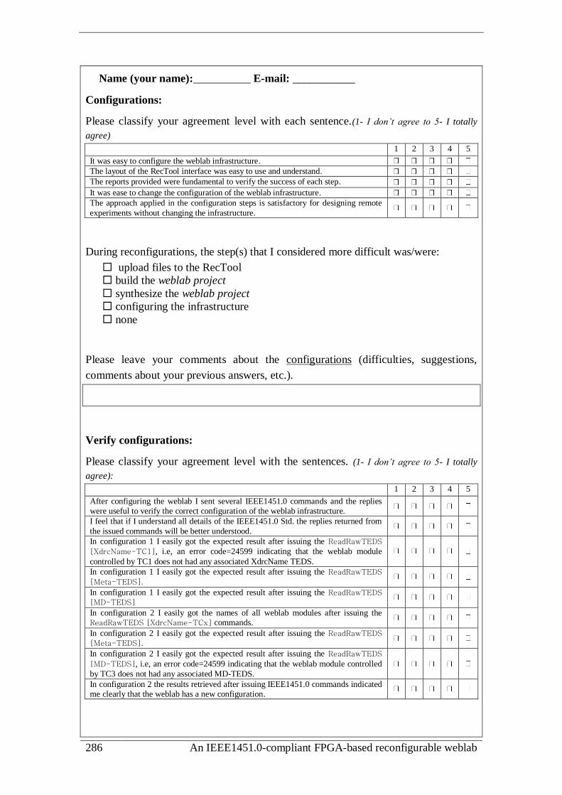
286 An IEEE1451.0-compliant FPGA-based reconfigurable weblab
Name (your name):___________ E-mail: ___________
Configurations:
Please classify your agreement level with each sentence.(1- I don’t agree to 5- I totally
agree)
1 2 3 4 5
It was easy to configure the weblab infrastructure.
The layout of the RecTool interface was easy to use and understand.
The reports provided were fundamental to verify the success of each step.
It was ease to change the configuration of the weblab infrastructure.
The approach applied in the configuration steps is satisfactory for designing remote
experiments without changing the infrastructure.
During reconfigurations, the step(s) that I considered more difficult was/were:
upload files to the RecTool
build the weblab project
synthesize the weblab project
configuring the infrastructure
none
Please leave your comments about the configurations (difficulties, suggestions,
comments about your previous answers, etc.).
Verify configurations:
Please classify your agreement level with the sentences. (1- I don’t agree to 5- I totally
agree):
1 2 3 4 5
After configuring the weblab I sent several IEEE1451.0 commands and the replies were useful to verify the correct configuration of the weblab infrastructure.
I feel that if I understand all details of the IEEE1451.0 Std. the replies returned from
the issued commands will be better understood.
In configuration 1 I easily got the expected result after issuing the ReadRawTEDS
[XdrcName-TC1], i.e, an error code=24599 indicating that the weblab module
controlled by TC1 does not had any associated XdrcName TEDS.
In configuration 1 I easily got the expected result after issuing the ReadRawTEDS
[Meta-TEDS].
In configuration 1 I easily got the expected result after issuing the ReadRawTEDS [MD-TEDS]
In configuration 2 I easily got the names of all weblab modules after issuing the ReadRawTEDS [XdrcName-TCx] commands.
In configuration 2 I easily got the expected result after issuing the ReadRawTEDS
[Meta-TEDS].
In configuration 2 I easily got the expected result after issuing the ReadRawTEDS
[MD-TEDS], i.e, an error code=24599 indicating that the weblab module controlled
by TC3 does not had any associated MD-TEDS.
In configuration 2 the results retrieved after issuing IEEE1451.0 commands indicated me clearly that the weblab has a new configuration.

Annex M: Validation & Verification 287
Please leave your comments about the verifying configurations (general aspects that
you may want to share, comments about your previous answers, etc.).
weblab modules’ control:
Please classify your agreement level with each sentence. (1- I don’t agree to 5- I totally
agree): 1 2 3 4 5
I/O Modules used in the feedback connection:
In configuration 1 it was easy to control the I/O modules.
In configuration 1 the retrieved replies during the control of the I/O modules were satisfactory.
In configuration 2 it was easy to control the I/O Modules.
In configuration 2 the retrieved replies during the control of the I/O modules were satisfactory.
Step-motor control:
In configuration 1 the control of the step-motor was easy to do using the SMCM.
In configuration 1 the ability of redefining the MD-TEDS of the SMCM to control the step-motor is an interesting solution for controlling every type of weblab module.
In configuration 1 the use of the ReadRawTEDS[MD-TEDS] command gave me a concrete understanding that I was changing the contents of the MD-TEDS.
In configuration 2 it was easy to control the step-motor using the output module.
Please leave your comments about the weblab modules’ control and about your
previous answers (what you think about the followed approach, the use of TEDS,
etc…).
Section 3 - Relevance of the proposed solution)
Name (your name):___________ E-mail: ___________
Please classify your agreement level with the sentences. (1- I don’t agree to 5- I totally
agree):
1 2 3 4 5
The IEEE1451.0 Std. is interesting for implementing weblabs architectures.
The IEEE1451.0-HTTP API provides a useful standard to access the weblab modules.
The proposed weblab architecture (reconfigurable and standard-based) enables sharing/replicating weblab modules by different infrastructures.
The proposed weblab architecture (reconfigurable and standard-based) increases the flexibility for designing experiments using the same the infrastructure.
The proposed weblab architecture (reconfigurable and standard-based) contributes for reducing the costs involved in the development of weblab infrastructures and in the design of experiments.
The proposed weblab architecture (reconfigurable and standard-based) increases the
collaboration among institutions in the design of experiments and in the development of weblabs infrastructures.

288 An IEEE1451.0-compliant FPGA-based reconfigurable weblab
The proposed weblab architecture (reconfigurable and standard-based) is interesting,
since it enables defining different configurations and weblab modules to access target experiments without changing the physical platform that implements the underlying infrastructure (e.g. the feedback connection lines and the step-motor).
In the future I consider the use of an infrastructure similar to this one in my institution/classes.
In the future I consider developing more weblab modules compatible with
infrastructures similar to this one (eventually as a supervisor of a student).
Creating a worldwide repository of weblab modules will be an interesting solution to use similar weblabs.
Please leave your comments about the infrastructure (current implementation,
objectives and added value to remote experimentation, etc.).
The validation process and the scenario of utilization (you can suggest other
scenarios).
Please give me your opinion about the advantages and disadvantages of using the
proposed solution in the point of view of each actor (Students, Teachers, Developers,
Technicians and Administrators).
- Students:
Conduct experiments remotely using a device connected to the Internet. The access to control/monitor
a weblab, comprising several weblab modules and the experiment(s), is made using a web interface.
Real data is retrieved from the weblab so students can analyze it as they would do in a traditional
laboratory.
- Teachers:
Provide the theoretical and practical framework needed by students to conduct a remote experiment.
They can take the role of assistants/tutors providing pedagogical support during a laboratorial
activity, as they would do in a traditional laboratory.
- Developers:
Have the task of developing the entire weblab infrastructure so students, teachers and technical staff
may control/monitor the experiment(s) and, in some cases, the entire infrastructure (namely when it
may be remotely reconfigurable). Developers may be teachers. However, it depends on the domain of
the experiment, because providing a weblab requires informatics and electrical skills teachers may not
have.

Annex M: Validation & Verification 289
- Technicians:
Must ensure that the weblab infrastructure and the experiments are always ready to be accessed.
Guaranteeing that the weblab modules are always up and running (with network communications up)
and the setup of specific experiments, are the main requirements that technicians should be aware of;
- Administrators:
They are the institutional managers that should be concerned with the supporting tools required to
provide remote experiments. They should be aware of issues like: i) ensure that collaborative tools are
available; ii) the institutional network infrastructure is always up and running; iii) guarantee the
correct access scheduling to the weblab, etc.
Other comments you fell interesting to give me (e.g. future work, ideas, etc.).
Thanks for your cooperation!
M.4 - Examples of webpages with the provided methodology
This annex presents screenshots of the supporting webpage, namely the stages
followed by the researchers (figure M.3) and some examples of the webpages used
during the validation and verification process (figure M.4).
Figure M.3: Table grid provided in the supporting webpage with the different stages of
the adopted methodology in the validation and reconfiguration process.

290 An IEEE1451.0-compliant FPGA-based reconfigurable weblab
11 2
3
4 5
Figure M.4: Examples of webpages used during the validation and verification process.
(1- steps followed during a reconfiguration; 2- control of the step motor in the second configuration;
3- image illustrating the second configuration of the infrastructure; 4- verification of the first
configuration ; 5- control the step-motor rotation in the first configuration)


![STUDOS DA GUERRA João Nunes Vicente[1]database.jornaldefesa.pt/assuntos_diversos_defesa/Estudos sobre o...2011/05/09 ESTUDOS SOBRE O FUTURO DO FENÓMENO DA GUERRA João Nunes Vicente[1]](https://img.pdfslide.us/doc/110x75/5c62993109d3f2ea708b5ca3/studos-da-guerra-joao-nunes-vicente1-sobre-o20110509-estudos-sobre-o-futuro.jpg)


![André Dumans Guedes @ Fevers [Eng]](https://img.pdfslide.us/doc/110x75/55cf919f550346f57b8f0585/andre-dumans-guedes-fevers-eng.jpg)