Embed Size (px)
DESCRIPTION
Rib Boom Drilling - a380
Citation preview
BOLTED REPAIRS1
EXIT
DRILLING
The Experience of drilling through composite is quite different than drilling through metal.
Composite can be very easily damaged so it is extremely important to follow carefully the
procedures during drilling operations
MENU
BOLTED REPAIRS2
EXIT
DRILLING
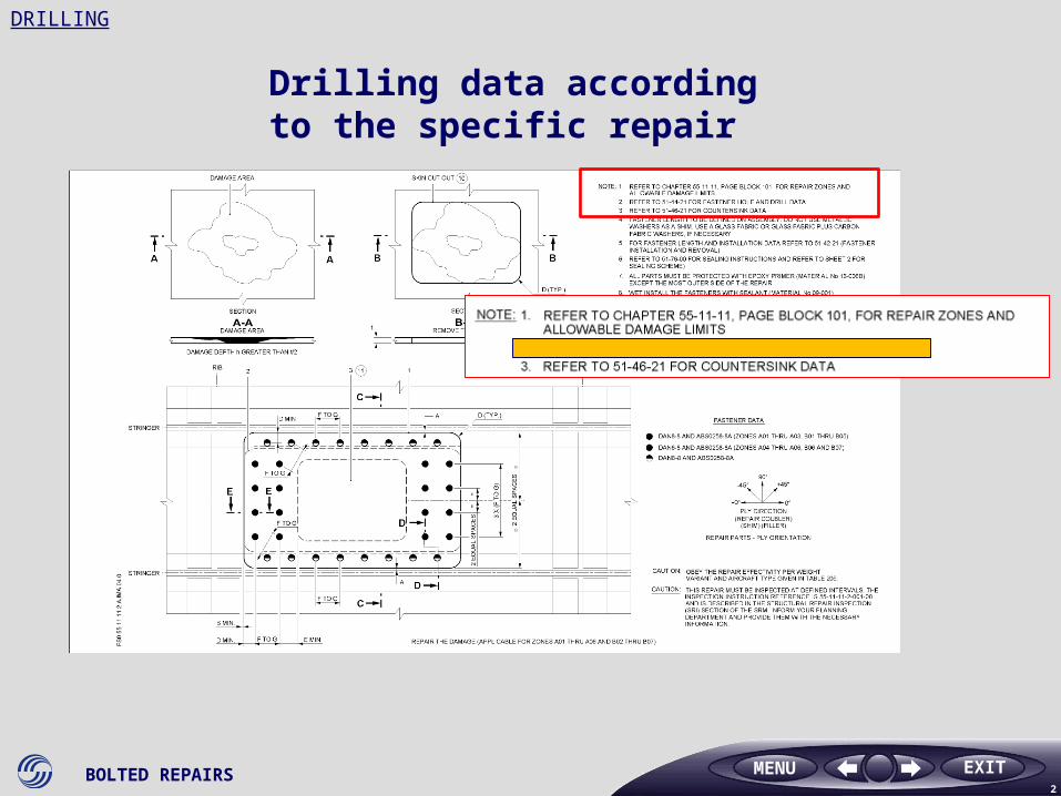
Drilling data according to the specific repair
MENU
BOLTED REPAIRS3
EXIT
DRILLING
MENU
BOLTED REPAIRS4
EXIT
DRILLING
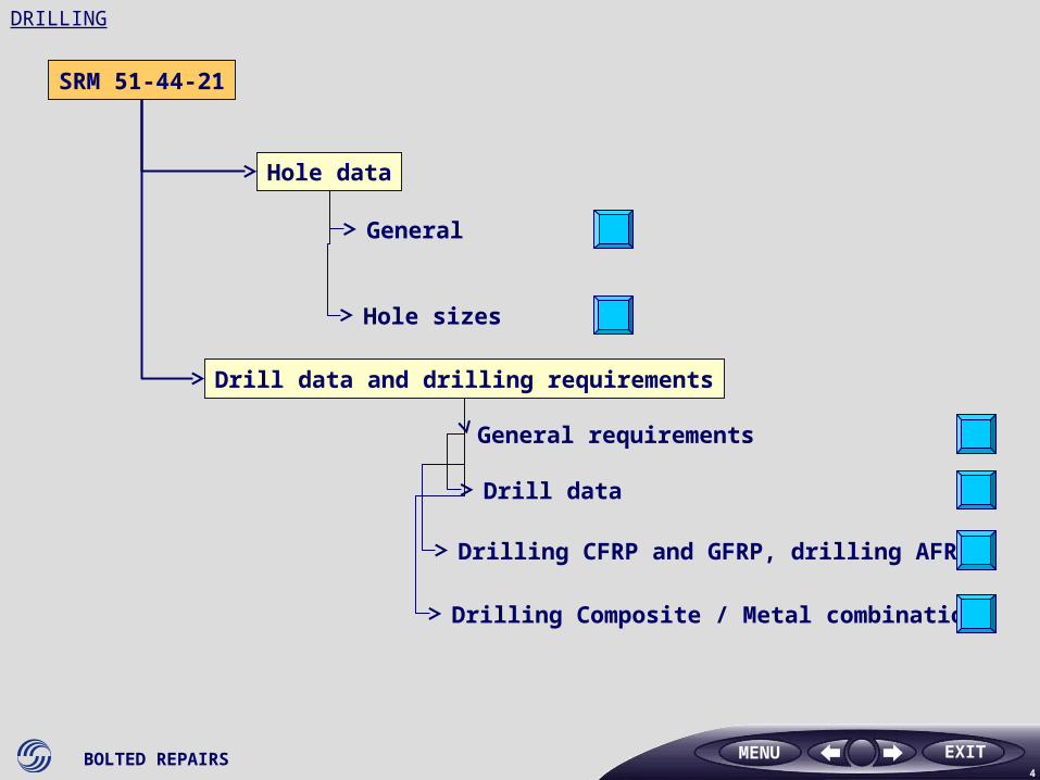
SRM 51-44-21
General
Hole sizes
Hole data
Drill data and drilling requirements
General requirements
Drill data
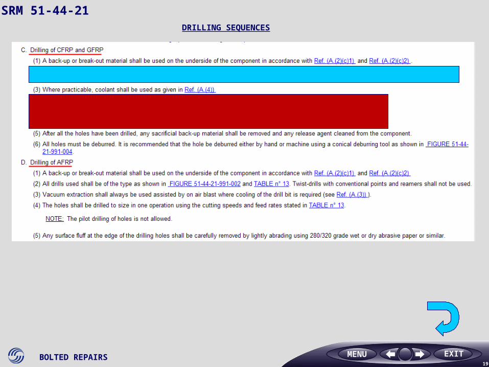
Drilling CFRP and GFRP, drilling AFRP
Drilling Composite / Metal combination
MENU
BOLTED REPAIRS5
EXIT
SRM 51-44-21
MENU
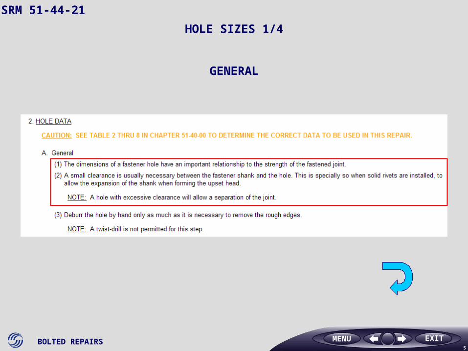
GENERAL
HOLE SIZES 1/4
BOLTED REPAIRS6
EXIT
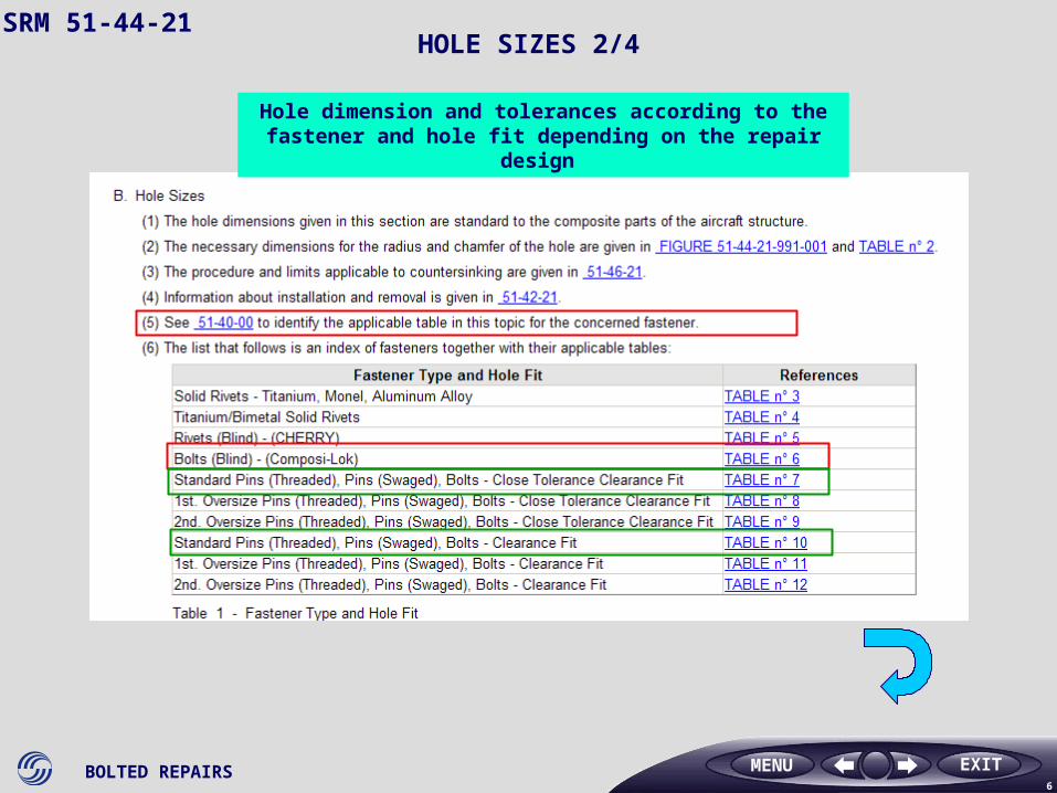
SRM 51-44-21HOLE SIZES 2/4
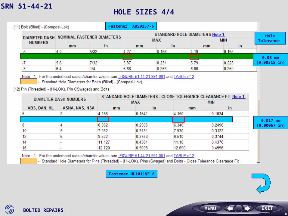
Hole dimension and tolerances according to the fastener and hole fit depending on the repair design
MENU
BOLTED REPAIRS7
EXIT
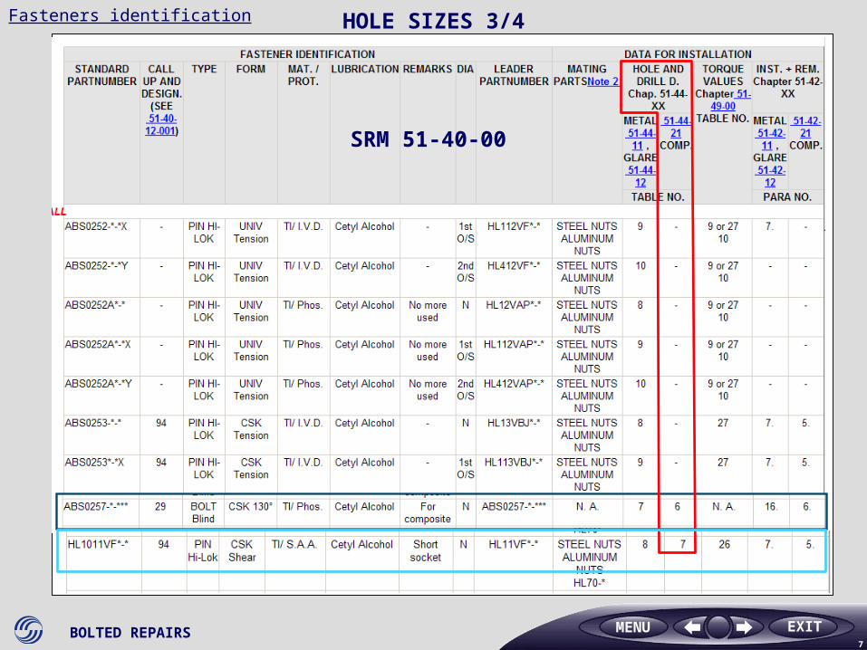
Fasteners identification
MENU
SRM 51-40-00
HOLE SIZES 3/4
BOLTED REPAIRS8
EXIT
SRM 51-44-21
Fastener HL1011VF 6
MENU
HOLE SIZES 4/4
Fastener ABS0257-6
Hole Tolerance
0.08 mm(0.00315 in)
0.017 mm(0.00067 in)
BOLTED REPAIRS9
EXIT
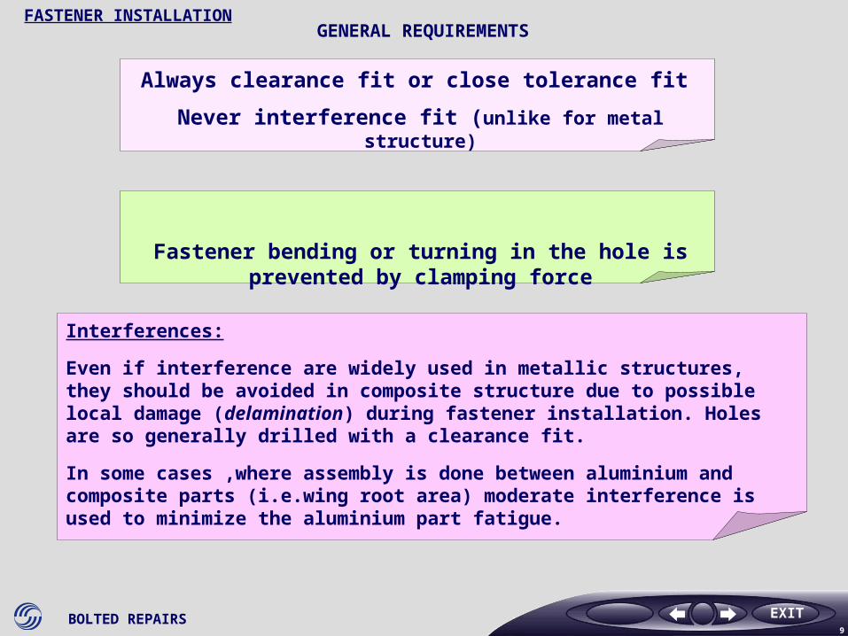
Always clearance fit or close tolerance fit
Never interference fit (unlike for metal structure)
Fastener bending or turning in the hole is prevented by clamping force
FASTENER INSTALLATION
Interferences:
Even if interference are widely used in metallic structures, they should be avoided in composite structure due to possible local damage (delamination) during fastener installation. Holes are so generally drilled with a clearance fit.
In some cases ,where assembly is done between aluminium and composite parts (i.e.wing root area) moderate interference is used to minimize the aluminium part fatigue.
GENERAL REQUIREMENTS
BOLTED REPAIRS10
EXIT
SRM 51-44-21
MENU
GENERAL REQUIREMENTS
BOLTED REPAIRS11
EXIT
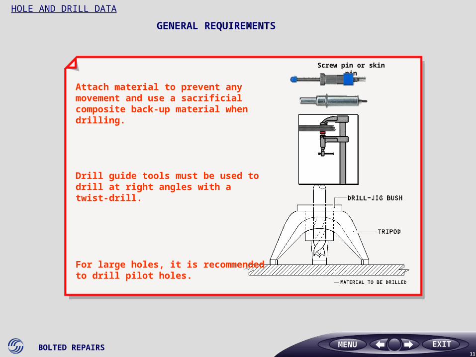
HOLE AND DRILL DATA
Attach material to prevent any movement and use a sacrificial composite back-up material when drilling.
Drill guide tools must be used to drill at right angles with a twist-drill.
For large holes, it is recommended to drill pilot holes.
Screw pin or skin pin
MENU
GENERAL REQUIREMENTS

BOLTED REPAIRS12
EXIT
According to the material to be drilled, the drill material and drill type
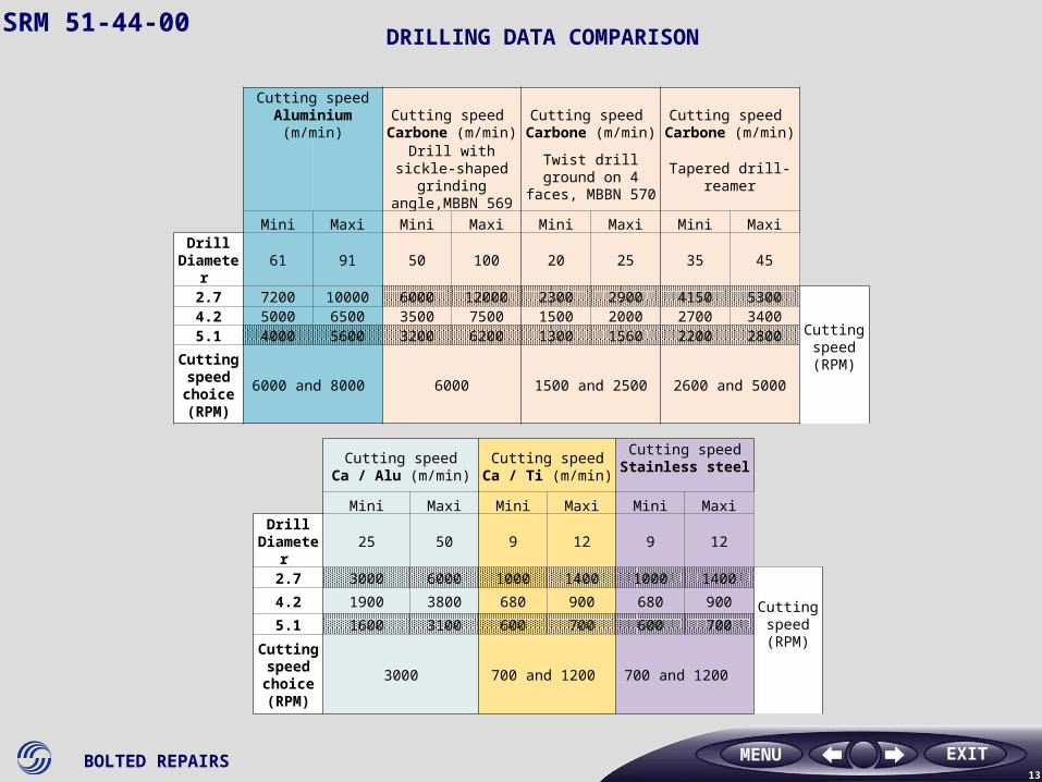
DRILLING DATASRM 51-44-21
MENU
BOLTED REPAIRS13
EXIT
Cutting speed Aluminium (m/min)
Cutting speed Carbone (m/min)
Cutting speed Carbone (m/min)
Cutting speed Carbone (m/min)
Drill with sickle-shaped grinding angle,MBBN 569
Twist drill ground on 4 faces, MBBN 570
Tapered drill-reamer
Mini Maxi Mini Maxi Mini Maxi Mini MaxiDrill
Diameter 61 91 50 100 20 25 35 45
2.7 7200 10000 6000 12000 2300 2900 4150 5300
Cutting speed (RPM)
4.2 5000 6500 3500 7500 1500 2000 2700 34005.1 4000 5600 3200 6200 1300 1560 2200 2800
Cutting speed choice (RPM)
6000 and 8000 6000 1500 and 2500 2600 and 5000
MENU
SRM 51-44-00
Cutting speed Ca / Alu (m/min)
Cutting speed Ca / Ti (m/min)
Cutting speed Stainless steel
Mini Maxi Mini Maxi Mini MaxiDrill
Diameter 25 50 9 12 9 12
2.7 3000 6000 1000 1400 1000 1400
Cutting speed (RPM)
4.2 1900 3800 680 900 680 900
5.1 1600 3100 600 700 600 700
Cutting speed choice (RPM)
3000 700 and 1200 700 and 1200
DRILLING DATA COMPARISON
BOLTED REPAIRS14
EXIT
SRM 51-44-21
MENU
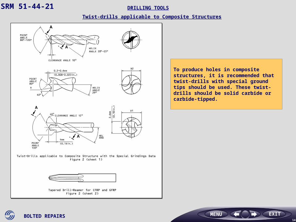
DRILLING TOOLS
Twist-drills applicable to Composite Structures
To produce holes in composite structures, it is recommended that twist-drills with special ground tips should be used. These twist-drills should be solid carbide or carbide-tipped.
BOLTED REPAIRS15
EXIT
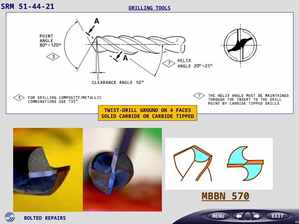
MBBN 570
TWIST-DRILL GROUND ON 4 FACESSOLID CARBIDE OR CARBIDE TIPPED
SRM 51-44-21 DRILLING TOOLS
MENU
BOLTED REPAIRS16
EXIT
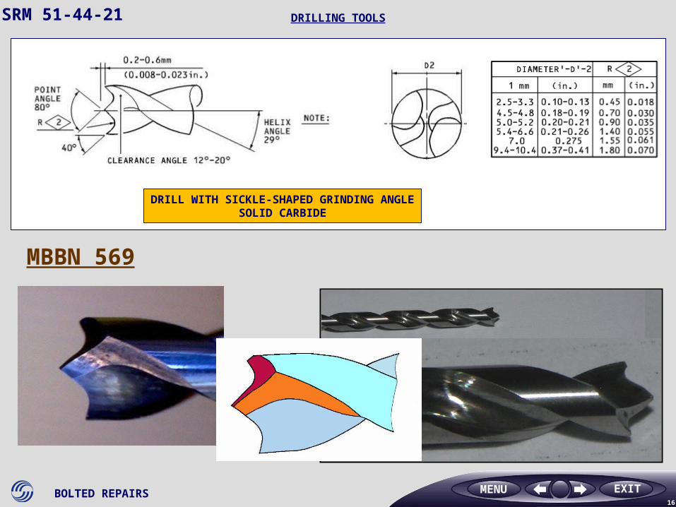
MBBN 569
DRILL WITH SICKLE-SHAPED GRINDING ANGLESOLID CARBIDE
SRM 51-44-21 DRILLING TOOLS
MENU
BOLTED REPAIRS17
EXIT
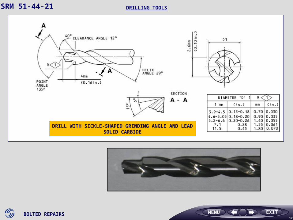
DRILL WITH SICKLE-SHAPED GRINDING ANGLE AND LEADSOLID CARBIDE
SRM 51-44-21 DRILLING TOOLS
MENU
BOLTED REPAIRS18
EXIT
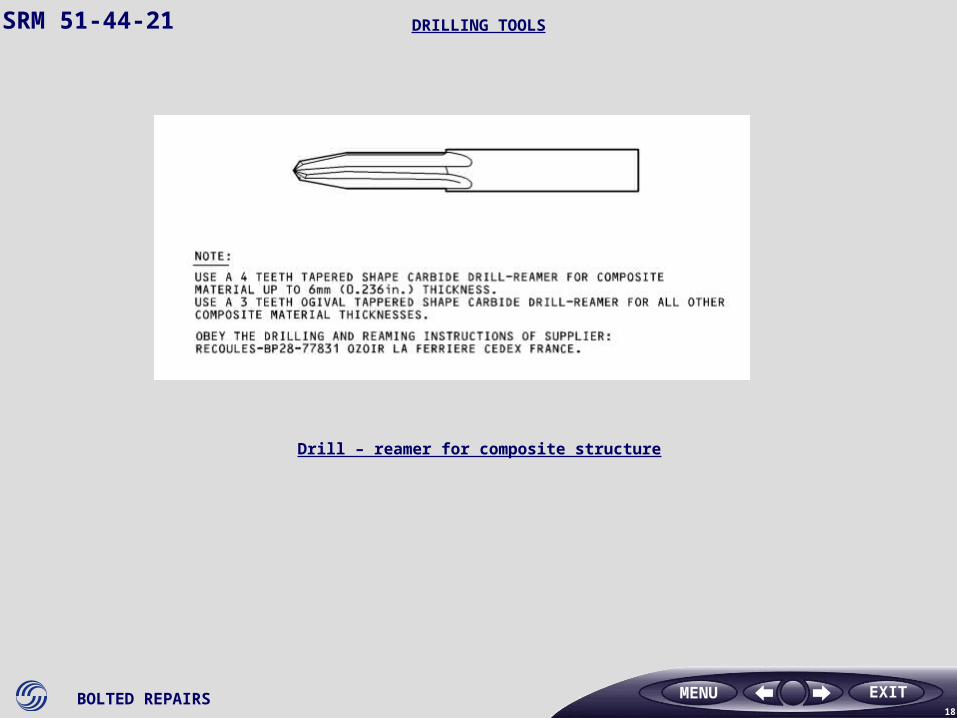
SRM 51-44-21 DRILLING TOOLS
Drill – reamer for composite structure
MENU
BOLTED REPAIRS19
EXIT
SRM 51-44-21
MENU
DRILLING SEQUENCES
BOLTED REPAIRS20
EXIT
SRM 51-44-21
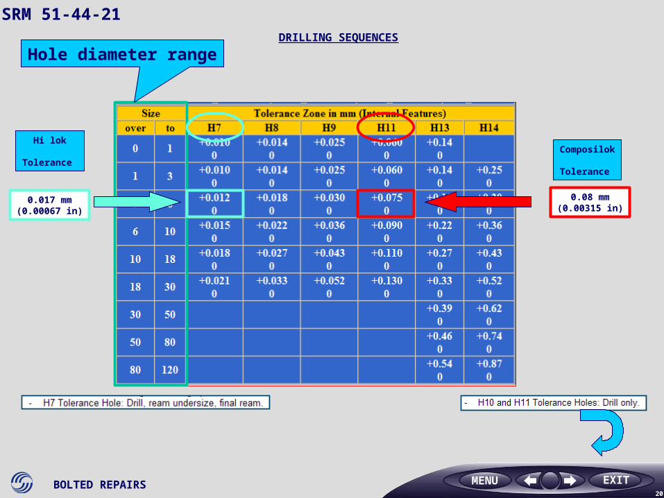
Hole diameter range
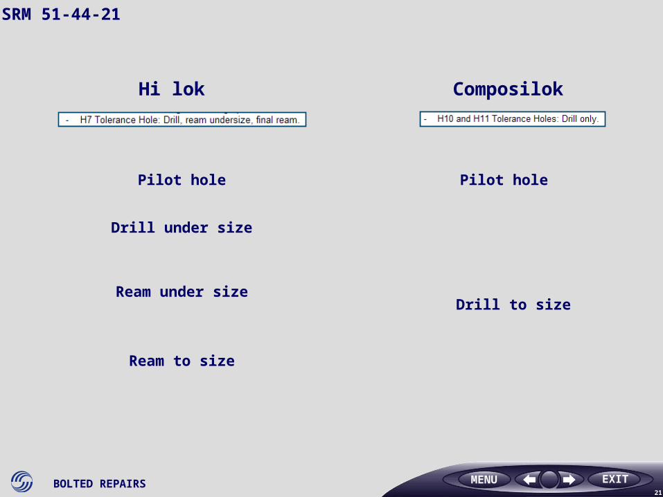
Composilok
Tolerance
0.08 mm(0.00315 in)
0.017 mm(0.00067 in)
Hi lok
Tolerance
DRILLING SEQUENCES
MENU
BOLTED REPAIRS21
EXIT
Hi lok Composilok
Pilot hole
Ream under size
Ream to size
Pilot hole
Drill to size
Drill under size
SRM 51-44-21
MENU
BOLTED REPAIRS22
EXIT
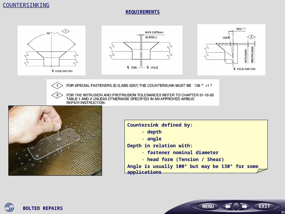
Countersink defined by:- depth- angle
Depth in relation with:- fastener nominal diameter - head form (Tension / Shear)
Angle is usually 100° but may be 130° for some applications
COUNTERSINKINGREQUIREMENTS
MENU
BOLTED REPAIRS23
EXIT
COUNTERSINKING
MENU
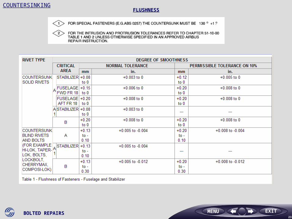
FLUSHNESS
BOLTED REPAIRS24
EXIT
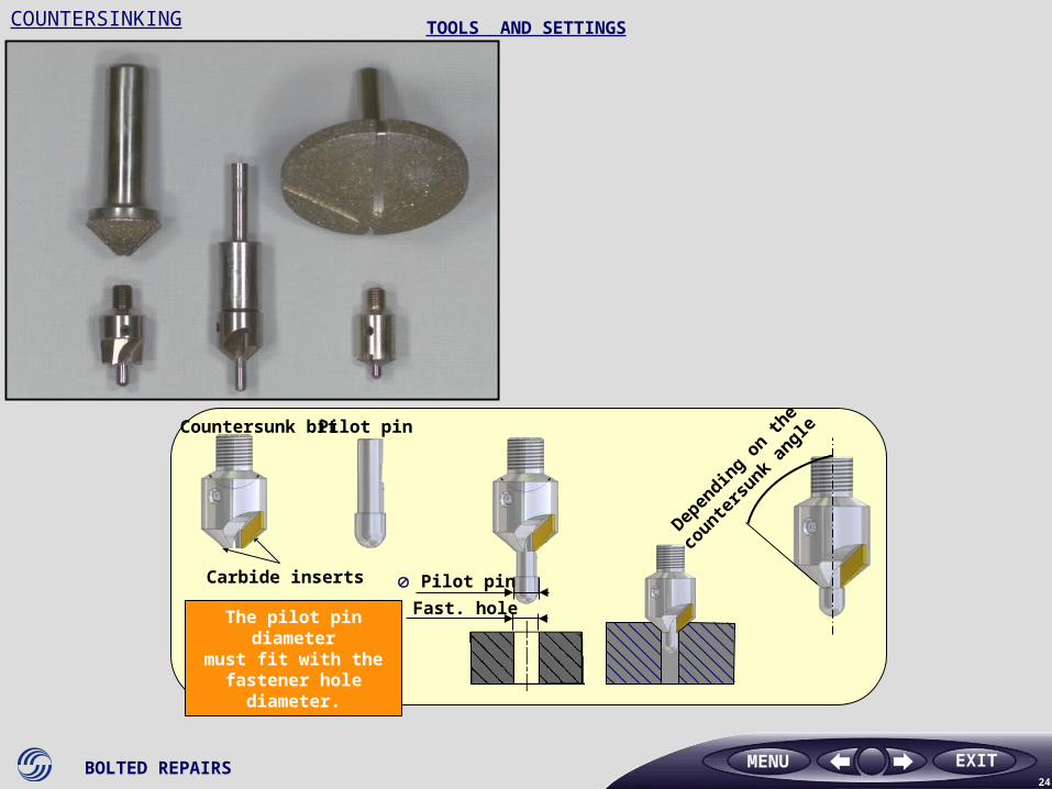
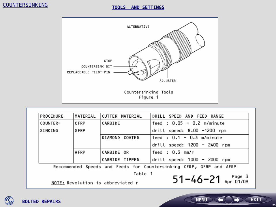
COUNTERSINKING TOOLS AND SETTINGS
Depen
ding o
n the
counte
rsunk
angle
Pilot pin
Fast. hole
Pilot pin Countersunk bit
The pilot pin diametermust fit with the
fastener hole diameter.
Carbide inserts
MENU
BOLTED REPAIRS25
EXIT
COUNTERSINKING TOOLS AND SETTINGS
MENU
BOLTED REPAIRS26
EXITMENU
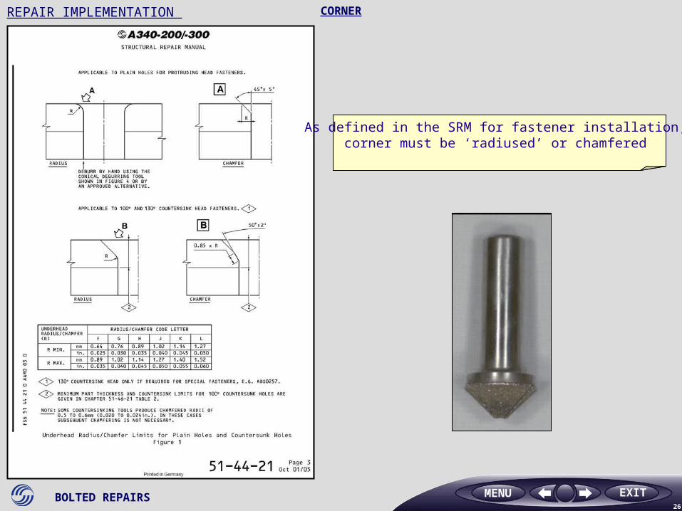
As defined in the SRM for fastener installation, corner must be ‘radiused’ or chamfered
CORNERREPAIR IMPLEMENTATION
BOLTED REPAIRS27
EXIT
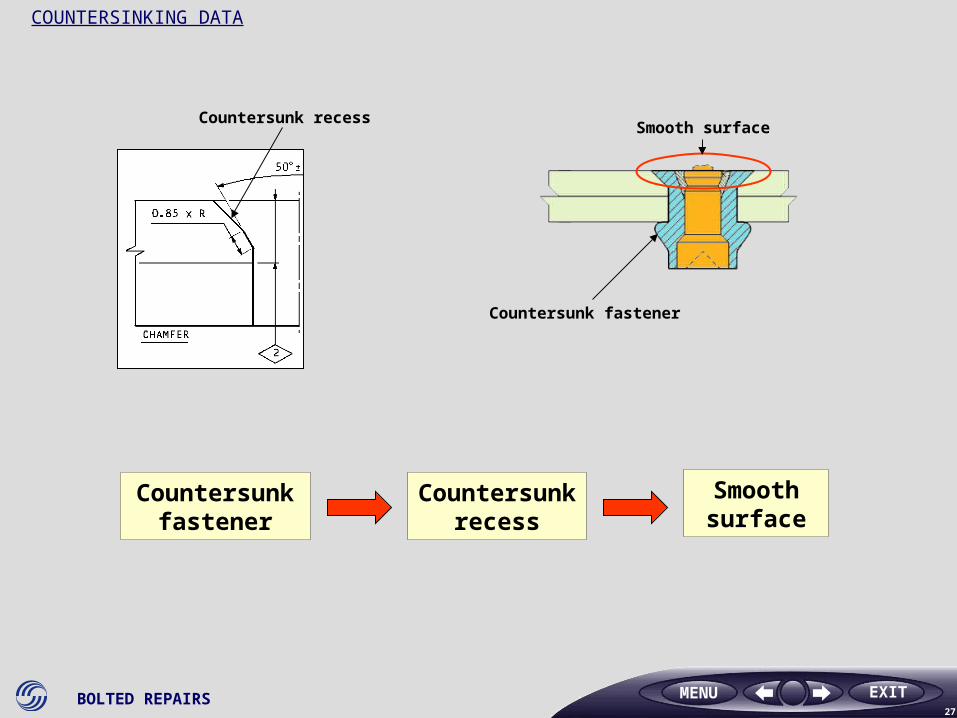
Countersunk recess
Countersunk fastener
Smooth surface
Countersunk fastener
Countersunk recess
Smooth surface
COUNTERSINKING DATA
MENU
BOLTED REPAIRS28
EXIT
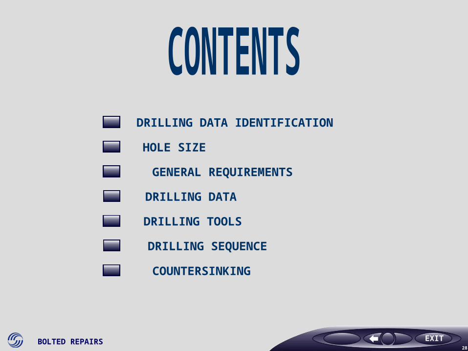
DRILLING DATA IDENTIFICATION
COUNTERSINKING
DRILLING SEQUENCE
DRILLING TOOLS
DRILLING DATA
GENERAL REQUIREMENTS
HOLE SIZE