Embed Size (px)
Citation preview
RI-ACC-ADR2 Demo Reader Reference Manual

REFERENCE MANUAL RI-ACC-ADR2 www.ti.com 11-07-21-024 – Rev. 1.0 – 2013-08-15
WARNING The LF antenna and antenna connections will be under high voltage while the LF interface is active. Touching adjacent electrical connections may lead to electric shock!
General TI High Voltage Evaluation (TI HV EVM) User Safety Guidelines Always follow TI’s set-up and application instructions, including use of all interface components within their recommended electrical rated voltage and power limits. Always use electrical safety precautions to help ensure your personal safety and those working around you. Contact TI’s Product Information Center http://support/ti./com for further information. Save all warnings and instructions for future reference. Failure to follow warnings and instructions may result in personal injury, property damage or death due to electrical shock and burn hazards. The term TI HV EVM refers to an electronic device typically provided as an open framed, unenclosed printed circuit board assembly. It is intended strictly for use in development laboratory environments, solely for qualified professional users having training, expertise and knowledge of electrical safety risks in development and application of high voltage electrical circuits. Any other use and/or application are strictly prohibited by Texas Instruments. If you are not suitable qualified, you should immediately stop from further use of the HV EVM.
1. Work Area Safety:
a. Keep work area clean and orderly. b. Qualified observer(s) must be present anytime circuits are energized. c. Effective barriers and signage must be present in the area where the TI HV EVM and its interface electronics are
energized; indicating operation of accessible high voltages may be present, for the purpose of protecting inadvertent access.
d. All interface circuits, power supplies, evaluation modules, instruments, meters, scopes and other related apparatus used in a development environment exceeding 50Vrms/75VDC must be electrically located within a protected Emergency Power Off EPO protected power strip.
e. Use stable and non-conductive work surface. f. Use adequately insulated clamps and wires to attach measurement probes and instruments. No freehand testing
whenever possible.
2. Electrical safety: As a precautionary measure, it is always a good engineering practice to assume that the entire EVM may have fully accessible and active high voltages.
a. De-energize the TI HV EVM and all its inputs, outputs and electrical loads before performing any electrical or other diagnostic measurements. Revalidate that TI HV EVM power has been safely de-energized.
b. With the EVM confirmed de-energized, proceed with required electrical circuit configurations, wiring, measurement equipment hook-ups and other application needs, while still assuming the EVM circuit and measuring instruments are electrically live.
c. Once EVM readiness is complete, energize the EVM as intended. WARNING: WHILE THE EVM IS ENERGIZED, NEVER TOUCH THE EVM OR ITS ELECTRICAL CIRCUITS AS THEY COULD BE AT HIGH VOLTAGES CAPABLE OF CAUSING ELECTRICAL SHOCK HAZARD.
3. Personal Safety 4.
a. Wear personal protective equipment e.g. latex gloves or safety glasses with side shields or protect EVM in an adequate lucent plastic box with interlocks from accidental touch.
Limitation for safe use: EVMs are not to be used as all or part of a production unit. TI HV EVM Safety Instruction, 19.09.2011
REFERENCE MANUAL RI-ACC-ADR2 www.ti.com 11-07-21-024 – Rev. 1.0 – 2013-08-15
Copyright © 2013, Texas Instruments Incorporated About this Manual Please submit documentation feedback 3 / 47
Important Note
The user is required to carefully read and understand the regularities described in chapter 10 prior to usage of this evaluation kit!
WARNING
Do not leave evaluation modules powered up while unattended
1 About this Manual
The AES Demo Software can be used to execute the main features of TI’s AES and 80-bit transponders along with a TI Demo Reader, such as the RI-ACC-ADR2. Resonant trimming, transponder communication and passive entry communication can be evaluated – depending on what reader is used. The Demo Software synchronizes settings with the device configuration to achieve valid data communication and response analyzing. Some devices only offer partial functionality (e.g. smaller memory or trimming only). This is not considered in the demo software and needs to be managed by the user. This manual describes the functionality of the AES Demo Software and serves also as manual for the RI-ACC-ADR2 evaluation module, though other readers can be used with this software. Each description presents a specific function in a general sense. Not all features and functions may be supported on all devices. The user should consult the device-specific data sheet for these details.
REFERENCE MANUAL RI-ACC-ADR2 www.ti.com 11-07-21-024 – Rev. 1.0 – 2013-08-15
Copyright © 2013, Texas Instruments Incorporated Table of Contents Please submit documentation feedback 4 / 47
2 Table of Contents
RI-ACC-ADR2 Demo Reader Reference Manual............................................................................................... 1
General TI High Voltage Evaluation (TI HV EVM) User Safety Guidelines .................................................... 2
1 About this Manual .......................................................................................................................................... 3
2 Table of Contents ........................................................................................................................................... 4
3 Table of Figures.............................................................................................................................................. 6
4 Definitions ....................................................................................................................................................... 7
5 Installation ...................................................................................................................................................... 8
5.1 Hardware Installation of RI-ACC-ADR2-10 Demo Reader ......................................................................... 8 5.2 Software Installation .................................................................................................................................... 8
6 RI-ACC-ADR2 Schematics ............................................................................................................................. 9
7 COM Ports .....................................................................................................................................................10
7.1 Initial Reader Search ................................................................................................................................10 7.2 Repeat Automatic Device Search .............................................................................................................12 7.3 Manual COM Port Connection ..................................................................................................................13
8 Software Functionality .................................................................................................................................14
8.1 Settings .....................................................................................................................................................14 8.2 Resonant Trimming ...................................................................................................................................15
8.2.1 Resonant Trimming (Reader controlled) ...........................................................................................16 8.3 Passive Entry, Passive Start with a CRAID (TMS37128) .........................................................................17 8.4 Immobilizer Read Page (DST80) ..............................................................................................................19
8.4.1 DST80 Transponder Immobilizer Timing Settings .............................................................................20 8.4.2 Example: Read Page 3 Telegram (DST80) .......................................................................................21 8.4.3 Example: Read Page 8 Response (DST80) ......................................................................................22
8.5 Immobilizer Program Page (DST80) .........................................................................................................23 8.5.1 Example: Program Page 8 Telegram (DST80) .................................................................................24
8.6 Immobilizer Lock Page (DST80) ...............................................................................................................25 8.6.1 Example: Lock Page 8 Telegram (DST80) ........................................................................................26
8.7 Using the TPIC84134 Antenna Extension Board ......................................................................................27 9 Serial Communication Protocol Description .............................................................................................28
9.1 RS232 / USB settings ...............................................................................................................................28 9.2 Setup Protocol ..........................................................................................................................................28 9.3 Setup Response Protocol .........................................................................................................................29
9.3.1 Setup Protocol Examples ..................................................................................................................29 9.4 Common Immobilizer Downlink Protocol ..................................................................................................30 9.5 Common Immobilizer Response Protocol ................................................................................................31 9.6 Block Check Character .............................................................................................................................32 9.7 Command Byte Definition .........................................................................................................................33 9.8 Specific Protocols .....................................................................................................................................34
9.8.1 CRAID PEPS Downlink Protocol .......................................................................................................34 9.8.2 CRAID PEPS Response / RKE Protocol ...........................................................................................34 9.8.3 DST80 Immobilizer Downlink Protocol ..............................................................................................35 9.8.4 Resonant Trimming Protocols ...........................................................................................................36
9.9 UHF Passive Entry/ Passive Start / Remote Keyless Entry Protocol .......................................................40 9.9.1 Communication Link Settings ............................................................................................................40 9.9.2 Communication Protocol ...................................................................................................................40
10 EVM Important Notice ..................................................................................................................................41
10.1 EVALUATION BOARD/KIT/MODULE (EVM) ADDITIONAL TERMS.....................................................41 10.2 REGULATORY COMPLIANCE INFORMATION ....................................................................................41 10.3 Important Notice for Users of this Product in Japan ...............................................................................43 10.4 EVALUATION BOARD/KIT/MODULE (EVM)WARNINGS, RESTRICTIONS AND DISCLAIMERS ......44
REFERENCE MANUAL RI-ACC-ADR2 www.ti.com 11-07-21-024 – Rev. 1.0 – 2013-08-15
Copyright © 2013, Texas Instruments Incorporated Table of Contents Please submit documentation feedback 5 / 47
11 Revision History ...........................................................................................................................................46
REFERENCE MANUAL RI-ACC-ADR2 www.ti.com 11-07-21-024 – Rev. 1.0 – 2013-08-15
Copyright © 2013, Texas Instruments Incorporated Table of Figures Please submit documentation feedback 6 / 47
3 Table of Figures
Figure 1: Base Station Schematics ................................................................................................................... 9 Figure 2: COM Port Search...............................................................................................................................10 Figure 3: Connected Hardware Tools .............................................................................................................11 Figure 4: New Automatic Device Search ........................................................................................................12 Figure 5: Toggle Manual Selection / Automatic Search of COM Port ..........................................................13 Figure 6: Access Settings Menu ......................................................................................................................14 Figure 7: Transfer Settings and Finished .......................................................................................................14 Figure 8: Resonant Frequency Trimming .......................................................................................................15 Figure 9: Configure CRAID EEPROM ..............................................................................................................17 Figure 10: Transponder: Read Page (DST80) .................................................................................................19 Figure 11: Coding Configuration (DST80) ......................................................................................................20 Figure 12: Example: Program Page 8 (DST80) ...............................................................................................23 Figure 13: Example: Lock Page 8 (DST80) .....................................................................................................25 Figure 14: TPIC connection ..............................................................................................................................27 Figure 15: Antenna Extension Configuration .................................................................................................27
REFERENCE MANUAL RI-ACC-ADR2 www.ti.com 11-07-21-024 – Rev. 1.0 – 2013-08-15
Copyright © 2013, Texas Instruments Incorporated Definitions Please submit documentation feedback 7 / 47
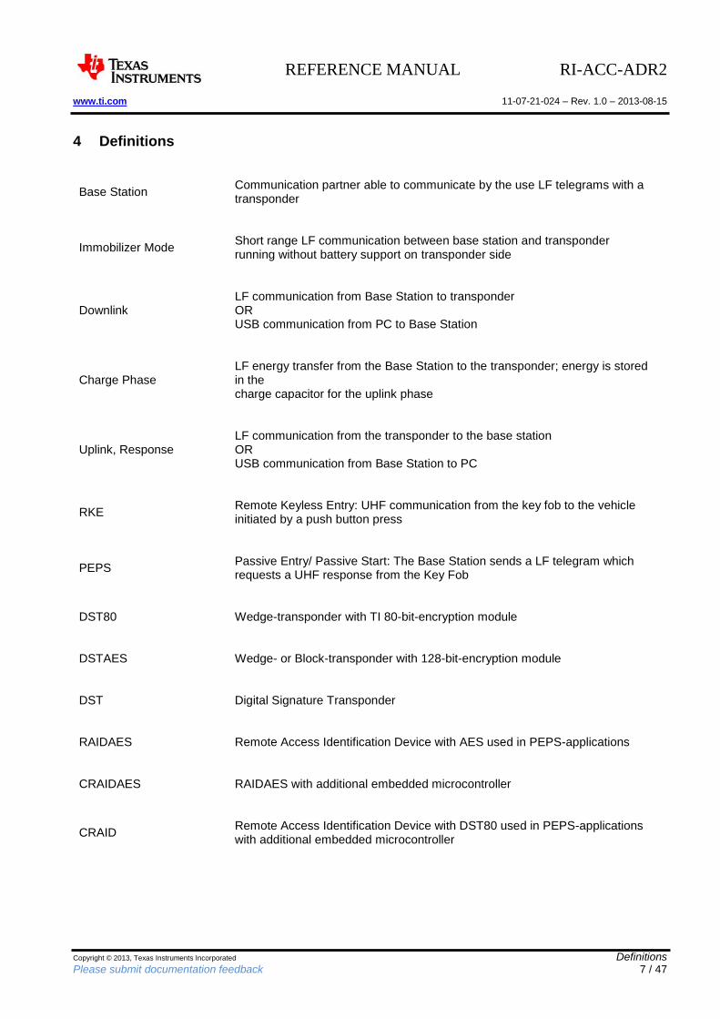
4 Definitions
Base Station
Communication partner able to communicate by the use LF telegrams with a transponder
Immobilizer Mode
Short range LF communication between base station and transponder running without battery support on transponder side
Downlink
LF communication from Base Station to transponder OR USB communication from PC to Base Station
Charge Phase
LF energy transfer from the Base Station to the transponder; energy is stored in the charge capacitor for the uplink phase
Uplink, Response
LF communication from the transponder to the base station OR USB communication from Base Station to PC
RKE
Remote Keyless Entry: UHF communication from the key fob to the vehicle initiated by a push button press
PEPS
Passive Entry/ Passive Start: The Base Station sends a LF telegram which requests a UHF response from the Key Fob
DST80 Wedge-transponder with TI 80-bit-encryption module
DSTAES Wedge- or Block-transponder with 128-bit-encryption module
DST Digital Signature Transponder
RAIDAES Remote Access Identification Device with AES used in PEPS-applications
CRAIDAES RAIDAES with additional embedded microcontroller
CRAID
Remote Access Identification Device with DST80 used in PEPS-applications with additional embedded microcontroller
REFERENCE MANUAL RI-ACC-ADR2 www.ti.com 11-07-21-024 – Rev. 1.0 – 2013-08-15
Copyright © 2013, Texas Instruments Incorporated Installation Please submit documentation feedback 8 / 47
5 Installation
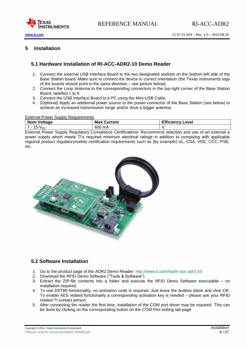
5.1 Hardware Installation of RI-ACC-ADR2-10 Demo Reader
1. Connect the external USB Interface Board to the two designated sockets on the bottom-left side of the Base Station board. Make sure to connect the device in correct orientation (the Texas Instruments logo of the boards should point in the same direction – see picture below).
2. Connect the Loop Antenna to the corresponding connectors in the top-right corner of the Base Station Board, labelled 1 to 6.
3. Connect the USB Interface Board to a PC using the Mini-USB Cable. 4. (Optional) Apply an additional power source to the power-connector of the Base Station (see below) to
achieve an increased transmission range and/or drive a bigger antenna.
External Power Supply Requirements
Nom Voltage Max Current Efficiency Level
7 - 15 VDC 600 mA V
External Power Supply Regulatory Compliance Certifications: Recommend selection and use of an external a power supply which meets TI’s required minimum electrical ratings in addition to complying with applicable regional product regulatory/safety certification requirements such as (by example) UL, CSA, VDE, CCC, PSE, etc.
5.2 Software Installation
1. Go to the product page of the ADR2 Demo Reader: http://www.ti.com/tool/ri-acc-adr2-10 2. Download the RFID Demo Software (“Tools & Software”) 3. Extract the ZIP-file contents into a folder and execute the RFID Demo Software executable – no
installation required. 4. To use DST80 functionality, no activation code is required. Just leave the textbox blank and click OK.
To enable AES related functionality a corresponding activation key is needed – please ask your RFID related TI contact person.
5. After connecting the reader the first time, installation of the COM port driver may be required. This can be done by clicking on the corresponding button on the COM Port setting tab page
REFERENCE MANUAL RI-ACC-ADR2 www.ti.com 11-07-21-024 – Rev. 1.0 – 2013-08-15
Copyright © 2013, Texas Instruments Incorporated RI-ACC-ADR2 Schematics Please submit documentation feedback 9 / 47
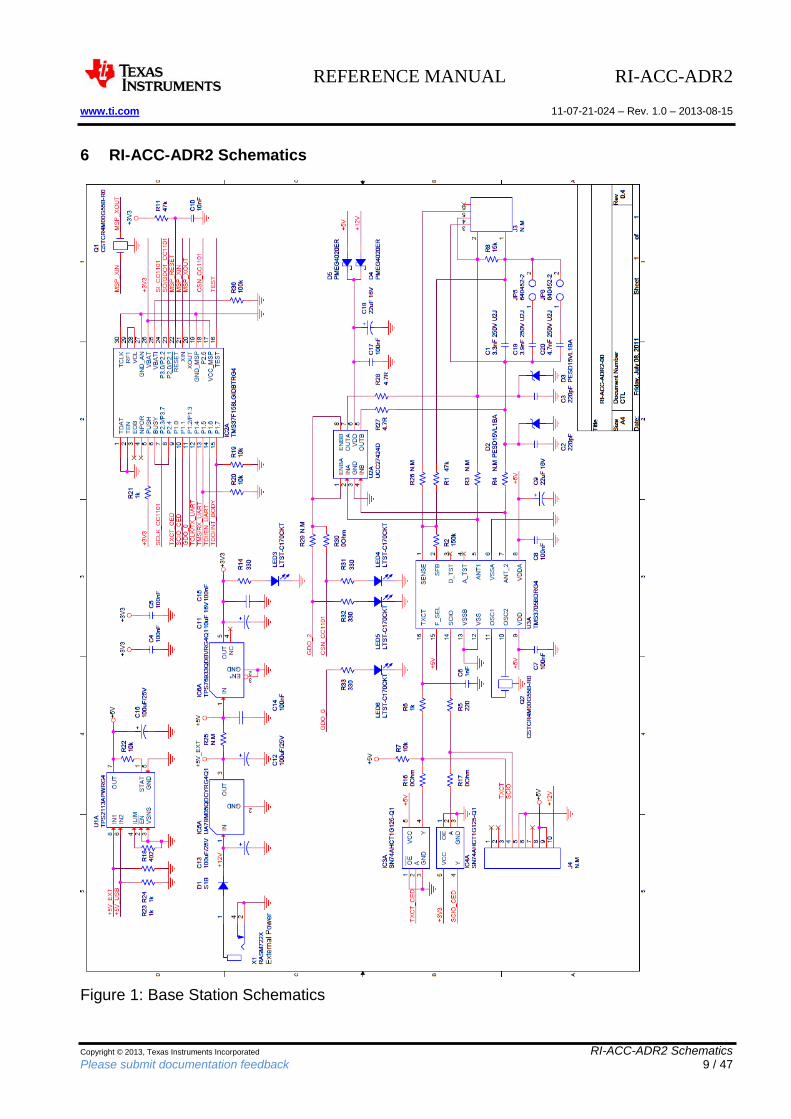
6 RI-ACC-ADR2 Schematics
Figure 1: Base Station Schematics
REFERENCE MANUAL RI-ACC-ADR2 www.ti.com 11-07-21-024 – Rev. 1.0 – 2013-08-15
Copyright © 2013, Texas Instruments Incorporated COM Ports Please submit documentation feedback 10 / 47
7 COM Ports
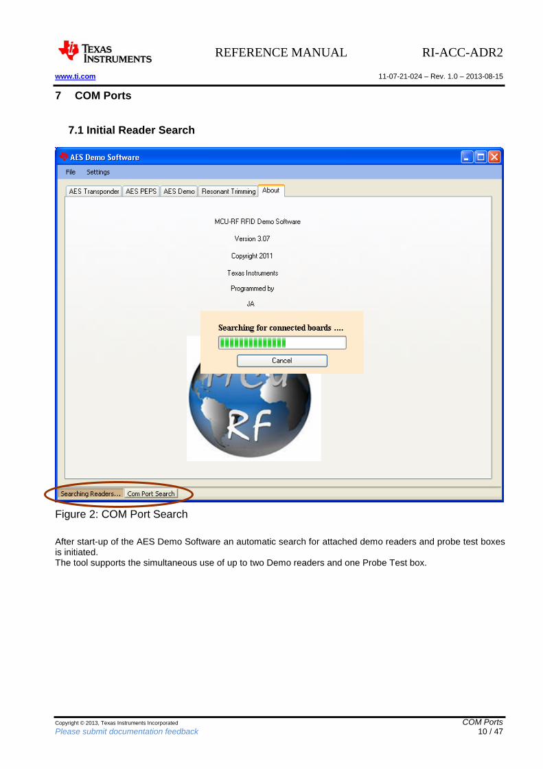
7.1 Initial Reader Search
Figure 2: COM Port Search
After start-up of the AES Demo Software an automatic search for attached demo readers and probe test boxes is initiated. The tool supports the simultaneous use of up to two Demo readers and one Probe Test box.
REFERENCE MANUAL RI-ACC-ADR2 www.ti.com 11-07-21-024 – Rev. 1.0 – 2013-08-15
Copyright © 2013, Texas Instruments Incorporated COM Ports Please submit documentation feedback 11 / 47
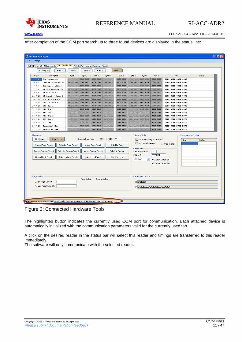
After completion of the COM port search up to three found devices are displayed in the status line:
Figure 3: Connected Hardware Tools
The highlighted button indicates the currently used COM port for communication. Each attached device is automatically initialized with the communication parameters valid for the currently used tab. A click on the desired reader in the status bar will select this reader and timings are transferred to this reader immediately. The software will only communicate with the selected reader.
REFERENCE MANUAL RI-ACC-ADR2 www.ti.com 11-07-21-024 – Rev. 1.0 – 2013-08-15
Copyright © 2013, Texas Instruments Incorporated COM Ports Please submit documentation feedback 12 / 47
7.2 Repeat Automatic Device Search
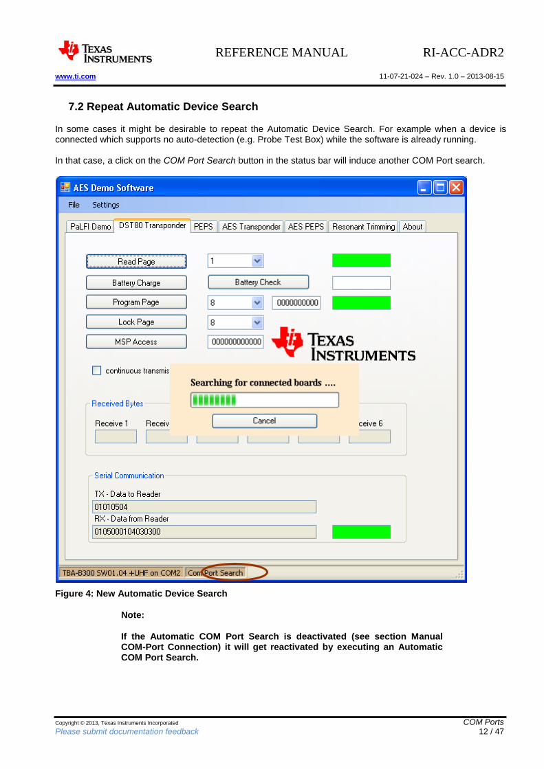
In some cases it might be desirable to repeat the Automatic Device Search. For example when a device is connected which supports no auto-detection (e.g. Probe Test Box) while the software is already running. In that case, a click on the COM Port Search button in the status bar will induce another COM Port search.
Figure 4: New Automatic Device Search
Note:
If the Automatic COM Port Search is deactivated (see section Manual COM-Port Connection) it will get reactivated by executing an Automatic COM Port Search.
REFERENCE MANUAL RI-ACC-ADR2 www.ti.com 11-07-21-024 – Rev. 1.0 – 2013-08-15
Copyright © 2013, Texas Instruments Incorporated COM Ports Please submit documentation feedback 13 / 47
7.3 Manual COM Port Connection
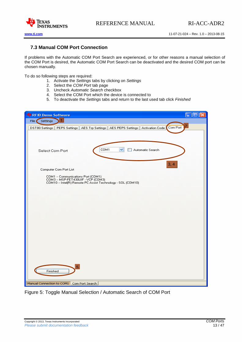
If problems with the Automatic COM Port Search are experienced, or for other reasons a manual selection of the COM Port is desired, the Automatic COM Port Search can be deactivated and the desired COM port can be chosen manually. To do so following steps are required:
1. Activate the Settings tabs by clicking on Settings 2. Select the COM Port tab page 3. Uncheck Automatic Search checkbox 4. Select the COM Port which the device is connected to 5. To deactivate the Settings tabs and return to the last used tab click Finished
Figure 5: Toggle Manual Selection / Automatic Search of COM Port
1
2
3, 4
5
REFERENCE MANUAL RI-ACC-ADR2 www.ti.com 11-07-21-024 – Rev. 1.0 – 2013-08-15
Copyright © 2013, Texas Instruments Incorporated Software Functionality Please submit documentation feedback 14 / 47
8 Software Functionality
8.1 Settings
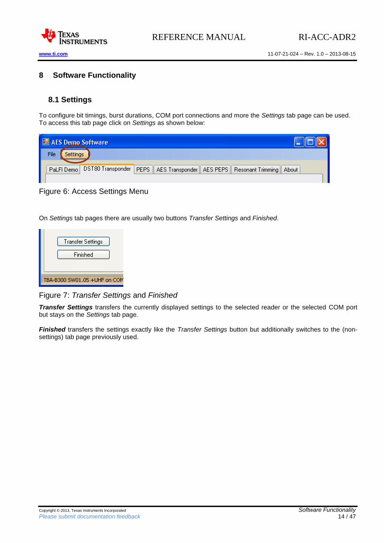
To configure bit timings, burst durations, COM port connections and more the Settings tab page can be used. To access this tab page click on Settings as shown below:
Figure 6: Access Settings Menu
On Settings tab pages there are usually two buttons Transfer Settings and Finished.
Figure 7: Transfer Settings and Finished
Transfer Settings transfers the currently displayed settings to the selected reader or the selected COM port but stays on the Settings tab page. Finished transfers the settings exactly like the Transfer Settings button but additionally switches to the (non-settings) tab page previously used.
REFERENCE MANUAL RI-ACC-ADR2 www.ti.com 11-07-21-024 – Rev. 1.0 – 2013-08-15
Copyright © 2013, Texas Instruments Incorporated Software Functionality Please submit documentation feedback 15 / 47
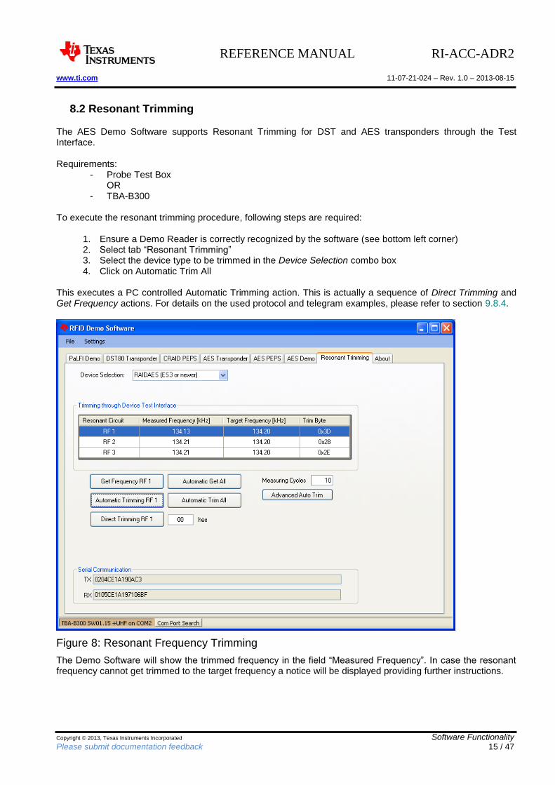
8.2 Resonant Trimming
The AES Demo Software supports Resonant Trimming for DST and AES transponders through the Test Interface. Requirements:
- Probe Test Box OR
- TBA-B300 To execute the resonant trimming procedure, following steps are required:
1. Ensure a Demo Reader is correctly recognized by the software (see bottom left corner) 2. Select tab “Resonant Trimming” 3. Select the device type to be trimmed in the Device Selection combo box 4. Click on Automatic Trim All
This executes a PC controlled Automatic Trimming action. This is actually a sequence of Direct Trimming and Get Frequency actions. For details on the used protocol and telegram examples, please refer to section 9.8.4.
Figure 8: Resonant Frequency Trimming
The Demo Software will show the trimmed frequency in the field “Measured Frequency”. In case the resonant frequency cannot get trimmed to the target frequency a notice will be displayed providing further instructions.
REFERENCE MANUAL RI-ACC-ADR2 www.ti.com 11-07-21-024 – Rev. 1.0 – 2013-08-15
Copyright © 2013, Texas Instruments Incorporated Software Functionality Please submit documentation feedback 16 / 47
8.2.1 Resonant Trimming (Reader controlled)
It’s also possible to perform a reader controlled automatic trimming of all channels. Requirements:
- TBA-B300
1. Select tab “Resonant Trimming” 2. Select the device to be trimmed in the Device Selection combo box 3. Click on Advanced Automatic Trimming button 4. Wait until results are shown in the table above. The orange LED3 on the Base Station indicates
trimming activity.
REFERENCE MANUAL RI-ACC-ADR2 www.ti.com 11-07-21-024 – Rev. 1.0 – 2013-08-15
Copyright © 2013, Texas Instruments Incorporated Software Functionality Please submit documentation feedback 17 / 47
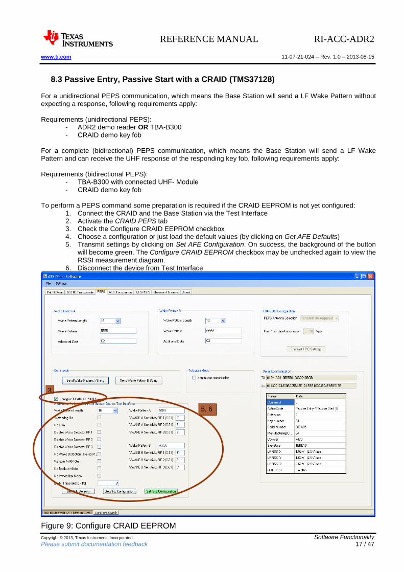
8.3 Passive Entry, Passive Start with a CRAID (TMS37128)
For a unidirectional PEPS communication, which means the Base Station will send a LF Wake Pattern without expecting a response, following requirements apply: Requirements (unidirectional PEPS):
- ADR2 demo reader OR TBA-B300 - CRAID demo key fob
For a complete (bidirectional) PEPS communication, which means the Base Station will send a LF Wake Pattern and can receive the UHF response of the responding key fob, following requirements apply: Requirements (bidirectional PEPS):
- TBA-B300 with connected UHF- Module - CRAID demo key fob
To perform a PEPS command some preparation is required if the CRAID EEPROM is not yet configured:
1. Connect the CRAID and the Base Station via the Test Interface 2. Activate the CRAID PEPS tab 3. Check the Configure CRAID EEPROM checkbox 4. Choose a configuration or just load the default values (by clicking on Get AFE Defaults) 5. Transmit settings by clicking on Set AFE Configuration. On success, the background of the button
will become green. The Configure CRAID EEPROM checkbox may be unchecked again to view the RSSI measurement diagram.
6. Disconnect the device from Test Interface
Figure 9: Configure CRAID EEPROM
3
5, 6
REFERENCE MANUAL RI-ACC-ADR2 www.ti.com 11-07-21-024 – Rev. 1.0 – 2013-08-15
Copyright © 2013, Texas Instruments Incorporated Software Functionality Please submit documentation feedback 18 / 47
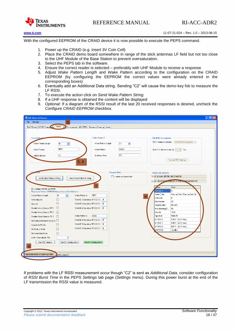
With the configured EEPROM of the CRAID device it is now possible to execute the PEPS command.
1. Power up the CRAID (e.g. insert 3V Coin Cell) 2. Place the CRAID demo board somewhere in range of the stick antennas LF field but not too close
to the UHF Module of the Base Station to prevent oversaturation. 3. Select the PEPS tab in the software. 4. Ensure the correct reader is selected – preferably with UHF Module to receive a response 5. Adjust Wake Pattern Length and Wake Pattern according to the configuration on the CRAID
EEPROM (by configuring the EEPROM the correct values were already entered in the corresponding boxes)
6. Eventually add an Additional Data string. Sending “C2” will cause the demo key fob to measure the LF RSSI.
7. To execute the action click on Send Wake Pattern String 8. If a UHF response is obtained the content will be displayed 9. Optional: If a diagram of the RSSI result of the last 20 received responses is desired, uncheck the
Configure CRAID EEPROM checkbox.
If problems with the LF RSSI measurement occur though “C2” is sent as Additional Data, consider configuration of RSSI Burst Time in the PEPS Settings tab page (Settings menu). During this power burst at the end of the LF transmission the RSSI value is measured.
3
4
5, 6
7 8
REFERENCE MANUAL RI-ACC-ADR2 www.ti.com 11-07-21-024 – Rev. 1.0 – 2013-08-15
Copyright © 2013, Texas Instruments Incorporated Software Functionality Please submit documentation feedback 19 / 47
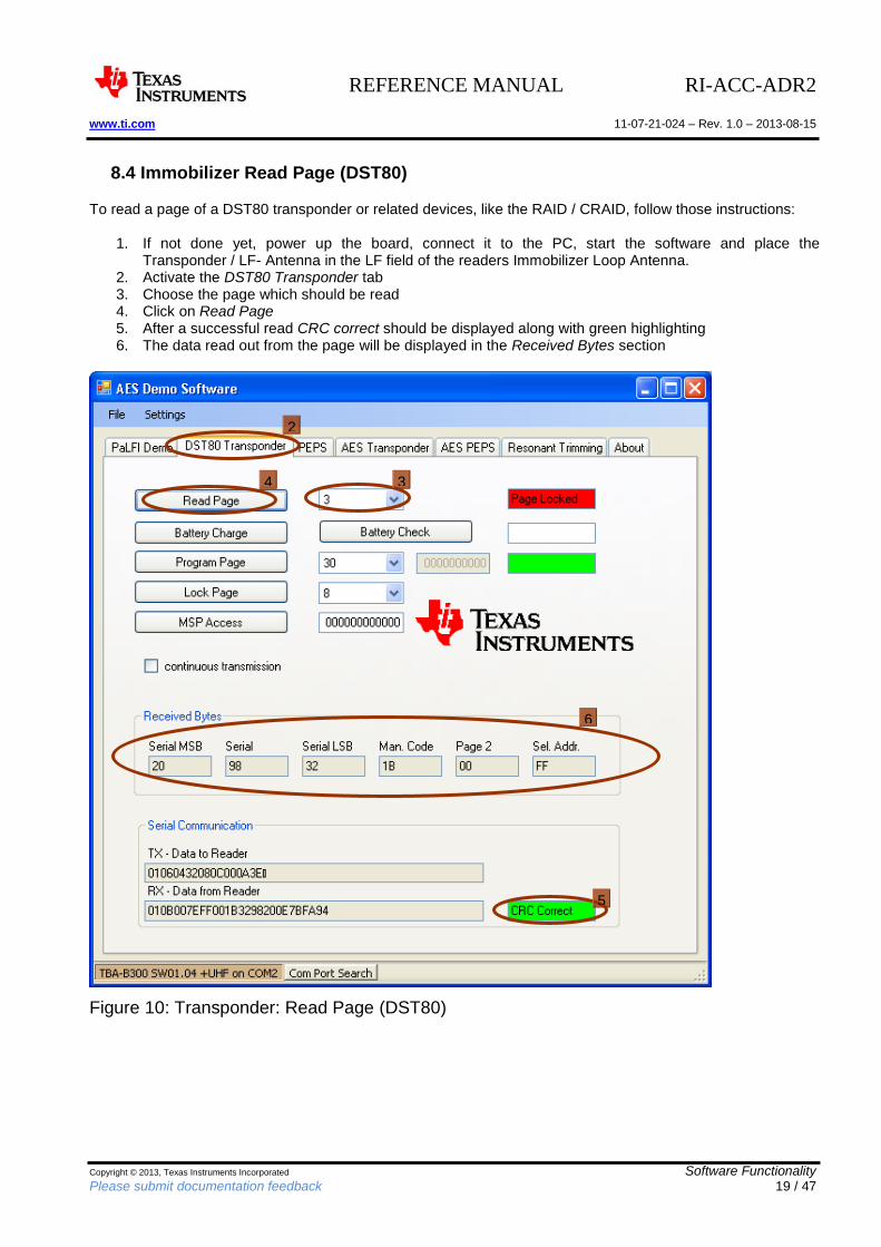
8.4 Immobilizer Read Page (DST80)
To read a page of a DST80 transponder or related devices, like the RAID / CRAID, follow those instructions:
1. If not done yet, power up the board, connect it to the PC, start the software and place the Transponder / LF- Antenna in the LF field of the readers Immobilizer Loop Antenna.
2. Activate the DST80 Transponder tab 3. Choose the page which should be read 4. Click on Read Page 5. After a successful read CRC correct should be displayed along with green highlighting 6. The data read out from the page will be displayed in the Received Bytes section
Figure 10: Transponder: Read Page (DST80)
2
3
4
5
6
REFERENCE MANUAL RI-ACC-ADR2 www.ti.com 11-07-21-024 – Rev. 1.0 – 2013-08-15
Copyright © 2013, Texas Instruments Incorporated Software Functionality Please submit documentation feedback 20 / 47
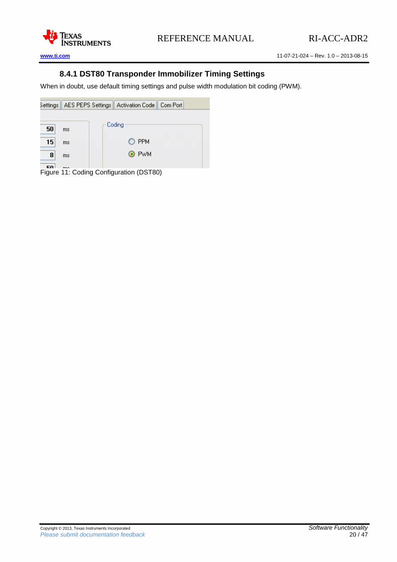
8.4.1 DST80 Transponder Immobilizer Timing Settings
When in doubt, use default timing settings and pulse width modulation bit coding (PWM).
Figure 11: Coding Configuration (DST80)
REFERENCE MANUAL RI-ACC-ADR2 www.ti.com 11-07-21-024 – Rev. 1.0 – 2013-08-15
Copyright © 2013, Texas Instruments Incorporated Software Functionality Please submit documentation feedback 21 / 47
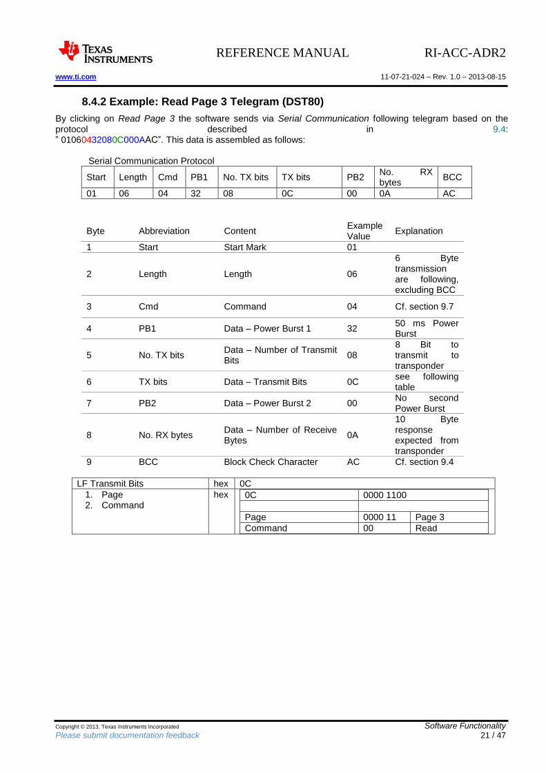
8.4.2 Example: Read Page 3 Telegram (DST80)
By clicking on Read Page 3 the software sends via Serial Communication following telegram based on the protocol described in 9.4: ” 01060432080C000AAC”. This data is assembled as follows: Serial Communication Protocol
Start Length Cmd PB1 No. TX bits TX bits PB2 No. RX bytes
BCC
01 06 04 32 08 0C 00 0A AC
Byte Abbreviation Content Example Value
Explanation
1 Start Start Mark 01
2 Length Length 06
6 Byte transmission are following, excluding BCC
3 Cmd Command 04 Cf. section 9.7
4 PB1 Data – Power Burst 1 32 50 ms Power Burst
5 No. TX bits Data – Number of Transmit Bits
08 8 Bit to transmit to transponder
6 TX bits Data – Transmit Bits 0C see following table
7 PB2 Data – Power Burst 2 00 No second Power Burst
8 No. RX bytes Data – Number of Receive Bytes
0A
10 Byte response expected from transponder
9 BCC Block Check Character AC Cf. section 9.4
LF Transmit Bits hex 0C
1. Page 2. Command
hex 0C 0000 1100
Page 0000 11 Page 3
Command 00 Read
REFERENCE MANUAL RI-ACC-ADR2 www.ti.com 11-07-21-024 – Rev. 1.0 – 2013-08-15
Copyright © 2013, Texas Instruments Incorporated Software Functionality Please submit documentation feedback 22 / 47
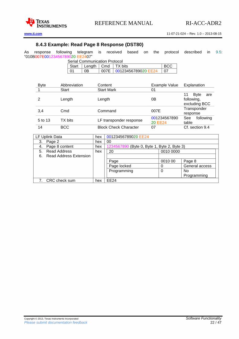
8.4.3 Example: Read Page 8 Response (DST80)
As response following telegram is received based on the protocol described in 9.5: “010B007E00123456789020 EE2407” Serial Communication Protocol
Start Length Cmd TX bits BCC
01 0B 007E 00123456789020 EE24 07
Byte Abbreviation Content Example Value Explanation 1 Start Start Mark 01
2 Length Length 0B 11 Byte are following, excluding BCC
3,4 Cmd Command 007E Transponder response
5 to 13 TX bits LF transponder response 00123456789020 EE24
See following table
14 BCC Block Check Character 07 Cf. section 9.4
LF Uplink Data hex 00123456789020 EE24
3. Page 2 hex 00
4. Page 8 content hex 1234567890 (Byte 0, Byte 1, Byte 2, Byte 3)
5. Read Address 6. Read Address Extension
hex 20 0010 0000
Page 0010 00 Page 8
Page locked 0 General access
Programming 0 No Programming
7. CRC check sum hex EE24
REFERENCE MANUAL RI-ACC-ADR2 www.ti.com 11-07-21-024 – Rev. 1.0 – 2013-08-15
Copyright © 2013, Texas Instruments Incorporated Software Functionality Please submit documentation feedback 23 / 47
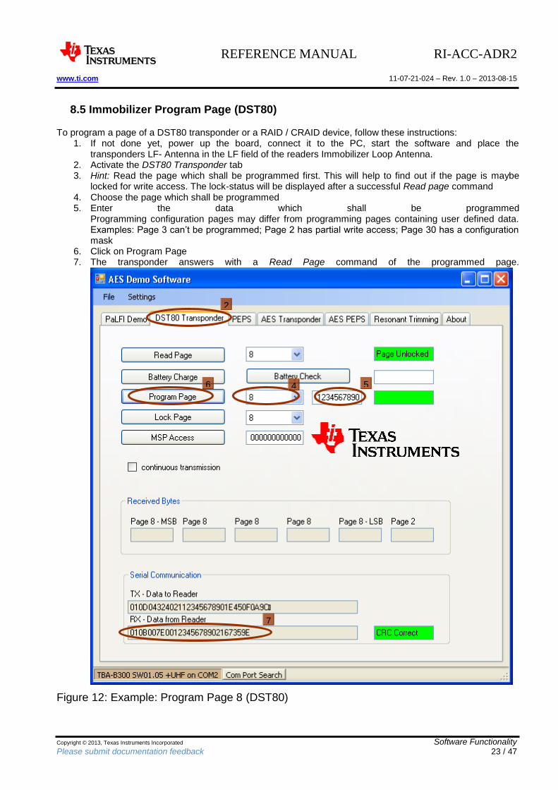
8.5 Immobilizer Program Page (DST80)
To program a page of a DST80 transponder or a RAID / CRAID device, follow these instructions: 1. If not done yet, power up the board, connect it to the PC, start the software and place the
transponders LF- Antenna in the LF field of the readers Immobilizer Loop Antenna. 2. Activate the DST80 Transponder tab 3. Hint: Read the page which shall be programmed first. This will help to find out if the page is maybe
locked for write access. The lock-status will be displayed after a successful Read page command 4. Choose the page which shall be programmed 5. Enter the data which shall be programmed
Programming configuration pages may differ from programming pages containing user defined data. Examples: Page 3 can’t be programmed; Page 2 has partial write access; Page 30 has a configuration mask
6. Click on Program Page 7. The transponder answers with a Read Page command of the programmed page.
Figure 12: Example: Program Page 8 (DST80)
2
4
6
5
76
REFERENCE MANUAL RI-ACC-ADR2 www.ti.com 11-07-21-024 – Rev. 1.0 – 2013-08-15
Copyright © 2013, Texas Instruments Incorporated Software Functionality Please submit documentation feedback 24 / 47
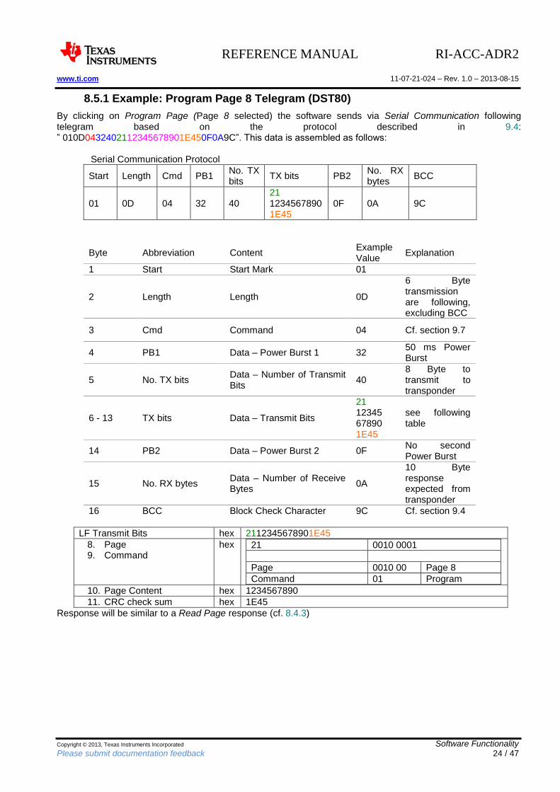
8.5.1 Example: Program Page 8 Telegram (DST80)
By clicking on Program Page (Page 8 selected) the software sends via Serial Communication following telegram based on the protocol described in 9.4: ” 010D0432402112345678901E450F0A9C”. This data is assembled as follows: Serial Communication Protocol
Start Length Cmd PB1 No. TX bits
TX bits PB2 No. RX bytes
BCC
01 0D 04 32 40 21 1234567890 1E45
0F 0A 9C
Byte Abbreviation Content Example Value
Explanation
1 Start Start Mark 01
2 Length Length 0D
6 Byte transmission are following, excluding BCC
3 Cmd Command 04 Cf. section 9.7
4 PB1 Data – Power Burst 1 32 50 ms Power Burst
5 No. TX bits Data – Number of Transmit Bits
40 8 Byte to transmit to transponder
6 - 13 TX bits Data – Transmit Bits
21 12345 67890 1E45
see following table
14 PB2 Data – Power Burst 2 0F No second Power Burst
15 No. RX bytes Data – Number of Receive Bytes
0A
10 Byte response expected from transponder
16 BCC Block Check Character 9C Cf. section 9.4
LF Transmit Bits hex 2112345678901E45
8. Page 9. Command
hex 21 0010 0001
Page 0010 00 Page 8
Command 01 Program
10. Page Content hex 1234567890
11. CRC check sum hex 1E45
Response will be similar to a Read Page response (cf. 8.4.3)
REFERENCE MANUAL RI-ACC-ADR2 www.ti.com 11-07-21-024 – Rev. 1.0 – 2013-08-15
Copyright © 2013, Texas Instruments Incorporated Software Functionality Please submit documentation feedback 25 / 47
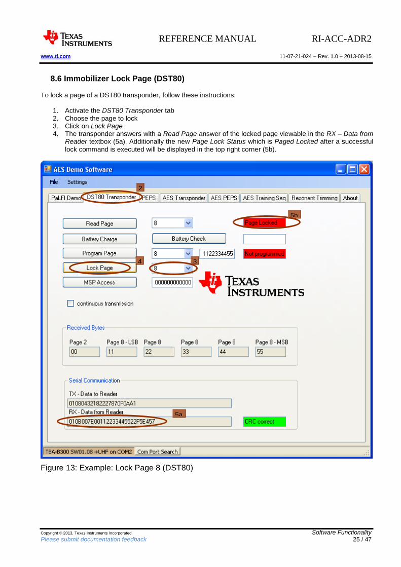
8.6 Immobilizer Lock Page (DST80)
To lock a page of a DST80 transponder, follow these instructions:
1. Activate the DST80 Transponder tab 2. Choose the page to lock 3. Click on Lock Page 4. The transponder answers with a Read Page answer of the locked page viewable in the RX – Data from
Reader textbox (5a). Additionally the new Page Lock Status which is Paged Locked after a successful lock command is executed will be displayed in the top right corner (5b).
Figure 13: Example: Lock Page 8 (DST80)
2
3
4
5a6
5b6
REFERENCE MANUAL RI-ACC-ADR2 www.ti.com 11-07-21-024 – Rev. 1.0 – 2013-08-15
Copyright © 2013, Texas Instruments Incorporated Software Functionality Please submit documentation feedback 26 / 47
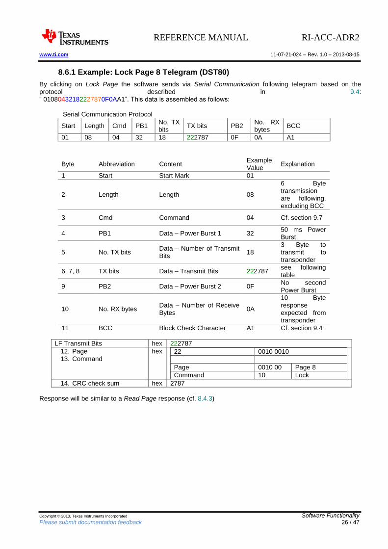
8.6.1 Example: Lock Page 8 Telegram (DST80)
By clicking on Lock Page the software sends via Serial Communication following telegram based on the protocol described in 9.4: ” 01080432182227870F0AA1”. This data is assembled as follows: Serial Communication Protocol
Start Length Cmd PB1 No. TX bits
TX bits PB2 No. RX bytes
BCC
01 08 04 32 18 222787 0F 0A A1
Byte Abbreviation Content Example Value
Explanation
1 Start Start Mark 01
2 Length Length 08
6 Byte transmission are following, excluding BCC
3 Cmd Command 04 Cf. section 9.7
4 PB1 Data – Power Burst 1 32 50 ms Power Burst
5 No. TX bits Data – Number of Transmit Bits
18 3 Byte to transmit to transponder
6, 7, 8 TX bits Data – Transmit Bits 222787 see following table
9 PB2 Data – Power Burst 2 0F No second Power Burst
10 No. RX bytes Data – Number of Receive Bytes
0A
10 Byte response expected from transponder
11 BCC Block Check Character A1 Cf. section 9.4
LF Transmit Bits hex 222787
12. Page 13. Command
hex 22 0010 0010
Page 0010 00 Page 8
Command 10 Lock
14. CRC check sum hex 2787
Response will be similar to a Read Page response (cf. 8.4.3)
REFERENCE MANUAL RI-ACC-ADR2 www.ti.com 11-07-21-024 – Rev. 1.0 – 2013-08-15
Copyright © 2013, Texas Instruments Incorporated Software Functionality Please submit documentation feedback 27 / 47
8.7 Using the TPIC84134 Antenna Extension Board
Requirements: - TBA-B300 Base Station - TPIC84134 Antenna Extension Board
To use the antenna extension board following steps are required:
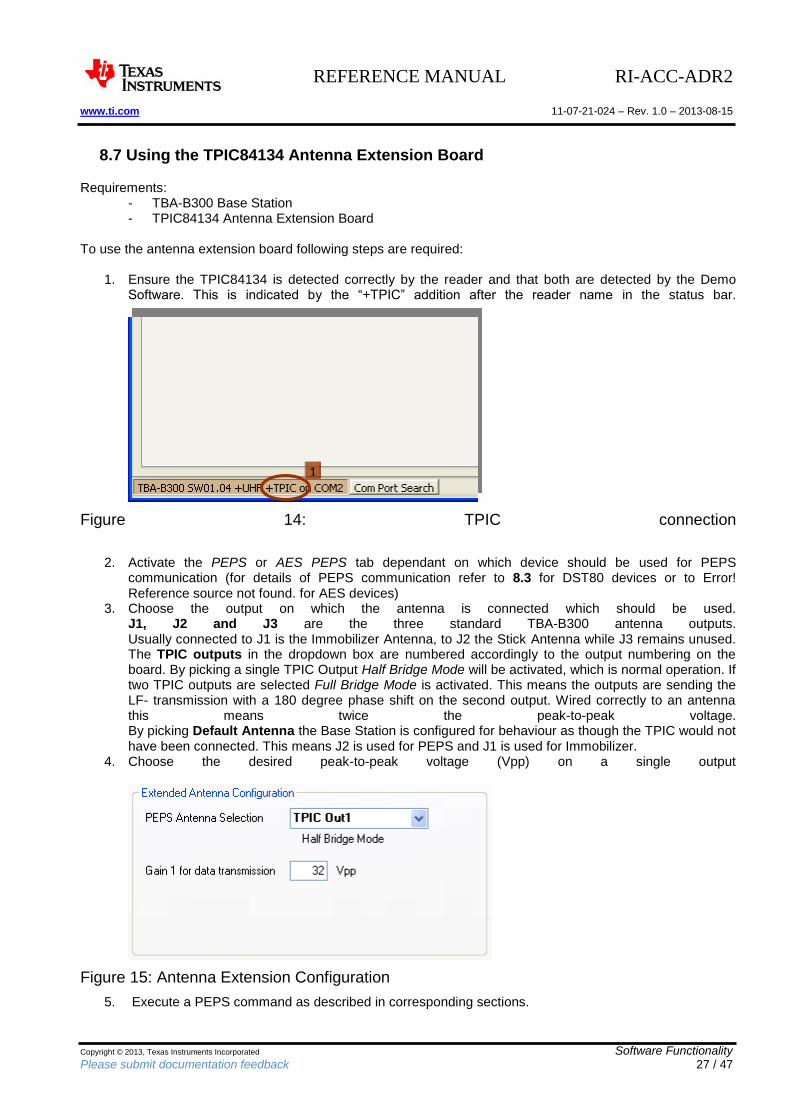
1. Ensure the TPIC84134 is detected correctly by the reader and that both are detected by the Demo Software. This is indicated by the “+TPIC” addition after the reader name in the status bar.
Figure 14: TPIC connection
2. Activate the PEPS or AES PEPS tab dependant on which device should be used for PEPS communication (for details of PEPS communication refer to 8.3 for DST80 devices or to Error! Reference source not found. for AES devices)
3. Choose the output on which the antenna is connected which should be used. J1, J2 and J3 are the three standard TBA-B300 antenna outputs. Usually connected to J1 is the Immobilizer Antenna, to J2 the Stick Antenna while J3 remains unused. The TPIC outputs in the dropdown box are numbered accordingly to the output numbering on the board. By picking a single TPIC Output Half Bridge Mode will be activated, which is normal operation. If two TPIC outputs are selected Full Bridge Mode is activated. This means the outputs are sending the LF- transmission with a 180 degree phase shift on the second output. Wired correctly to an antenna this means twice the peak-to-peak voltage. By picking Default Antenna the Base Station is configured for behaviour as though the TPIC would not have been connected. This means J2 is used for PEPS and J1 is used for Immobilizer.
4. Choose the desired peak-to-peak voltage (Vpp) on a single output
Figure 15: Antenna Extension Configuration
5. Execute a PEPS command as described in corresponding sections.
1
REFERENCE MANUAL RI-ACC-ADR2 www.ti.com 11-07-21-024 – Rev. 1.0 – 2013-08-15
Copyright © 2013, Texas Instruments Incorporated Serial Communication Protocol Description Please submit documentation feedback 28 / 47
9 Serial Communication Protocol Description
9.1 RS232 / USB settings
The RI-ACC-ADR2-00 reader is designed for engineering purposes. The data communication is performed via USB port but shows up as serial COM port on the PC side. The transmission parameters are 8 data bits, 1 stop bit, no parity and a speed of 9600 baud. No hardware or software handshake is used. The protocol data consists only of the following ASCII characters ‘0’,’1’, …,‘9’, ‘A’,…,’F’. The data communication between the PC and the reader is performed within a frame structure.
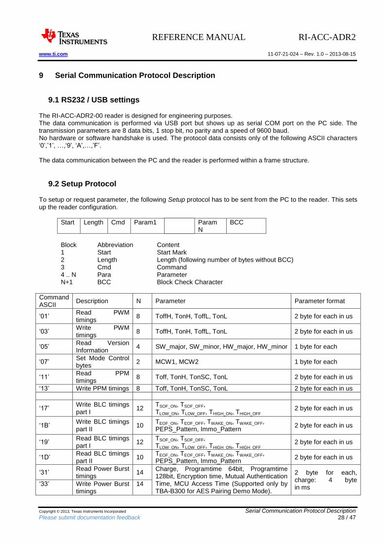
9.2 Setup Protocol
To setup or request parameter, the following Setup protocol has to be sent from the PC to the reader. This sets up the reader configuration.
Start Length Cmd Param1 Param N
BCC
Block Abbreviation Content 1 Start Start Mark 2 Length Length (following number of bytes without BCC) 3 Cmd Command 4 .. N Para Parameter N+1 BCC Block Check Character
Command ASCII
Description N Parameter Parameter format
‘01’ Read PWM timings
8 ToffH, TonH, ToffL, TonL 2 byte for each in us
‘03’ Write PWM timings
8 ToffH, TonH, ToffL, TonL 2 byte for each in us
‘05’ Read Version Information
4 SW_major, SW_minor, HW_major, HW_minor 1 byte for each
‘07’ Set Mode Control bytes
2 MCW1, MCW2 1 byte for each
‘11’ Read PPM timings
8 Toff, TonH, TonSC, TonL 2 byte for each in us
‘13’ Write PPM timings 8 Toff, TonH, TonSC, TonL 2 byte for each in us
‘17’ Write BLC timings part I
12 TSOF_ON, TSOF_OFF, TLOW_ON, TLOW_OFF, THIGH_ON, THIGH_OFF
2 byte for each in us
‘1B’ Write BLC timings part II
10 TEOF_ON, TEOF_OFF, TWAKE_ON, TWAKE_OFF, PEPS_Pattern, Immo_Pattern
2 byte for each in us
‘19’ Read BLC timings part I
12 TSOF_ON, TSOF_OFF, TLOW_ON, TLOW_OFF, THIGH_ON, THIGH_OFF
2 byte for each in us
‘1D’ Read BLC timings part II
10 TEOF_ON, TEOF_OFF, TWAKE_ON, TWAKE_OFF, PEPS_Pattern, Immo_Pattern
2 byte for each in us
‘31’ Read Power Burst timings
14 Charge, Programtime 64bit, Programtime 128bit, Encryption time, Mutual Authentication Time, MCU Access Time (Supported only by TBA-B300 for AES Pairing Demo Mode).
2 byte for each, charge: 4 byte in ms
‘33’ Write Power Burst timings
14
REFERENCE MANUAL RI-ACC-ADR2 www.ti.com 11-07-21-024 – Rev. 1.0 – 2013-08-15
Copyright © 2013, Texas Instruments Incorporated Serial Communication Protocol Description Please submit documentation feedback 29 / 47
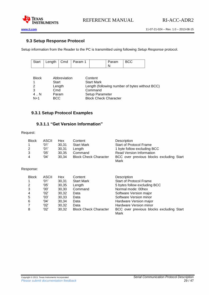
9.3 Setup Response Protocol
Setup information from the Reader to the PC is transmitted using following Setup Response protocol.
Start Length Cmd Param 1 Param N
BCC
Block Abbreviation Content 1 Start Start Mark 2 Length Length (following number of bytes without BCC) 3 Cmd Command 4 .. N Param Setup Parameter N+1 BCC Block Check Character
9.3.1 Setup Protocol Examples
9.3.1.1 “Get Version Information”
Request:
Block ASCII Hex Content Description 1 ‘01’ 30,31 Start Mark Start of Protocol Frame 2 ‘01’ 30,31 Length 1 byte follow excluding BCC 3 ‘05’ 30,35 Command Read Version Information 4 ‘04’ 30,34 Block Check Character BCC over previous blocks excluding Start
Mark Response:
Block ASCII Hex Content Description 1 ‘01’ 30,31 Start Mark Start of Protocol Frame 2 ‘05’ 30,35 Length 5 bytes follow excluding BCC 3 ‘00’ 30,30 Command Normal mode: 00hex 4 ‘02’ 30,32 Data Software Version major 5 ‘03’ 30,33 Data Software Version minor 6 ‘04’ 30,34 Data Hardware Version major 7 ‘02’ 30,32 Data Hardware Version minor 8 ‘02’ 30,32 Block Check Character BCC over previous blocks excluding Start
Mark
REFERENCE MANUAL RI-ACC-ADR2 www.ti.com 11-07-21-024 – Rev. 1.0 – 2013-08-15
Copyright © 2013, Texas Instruments Incorporated Serial Communication Protocol Description Please submit documentation feedback 30 / 47
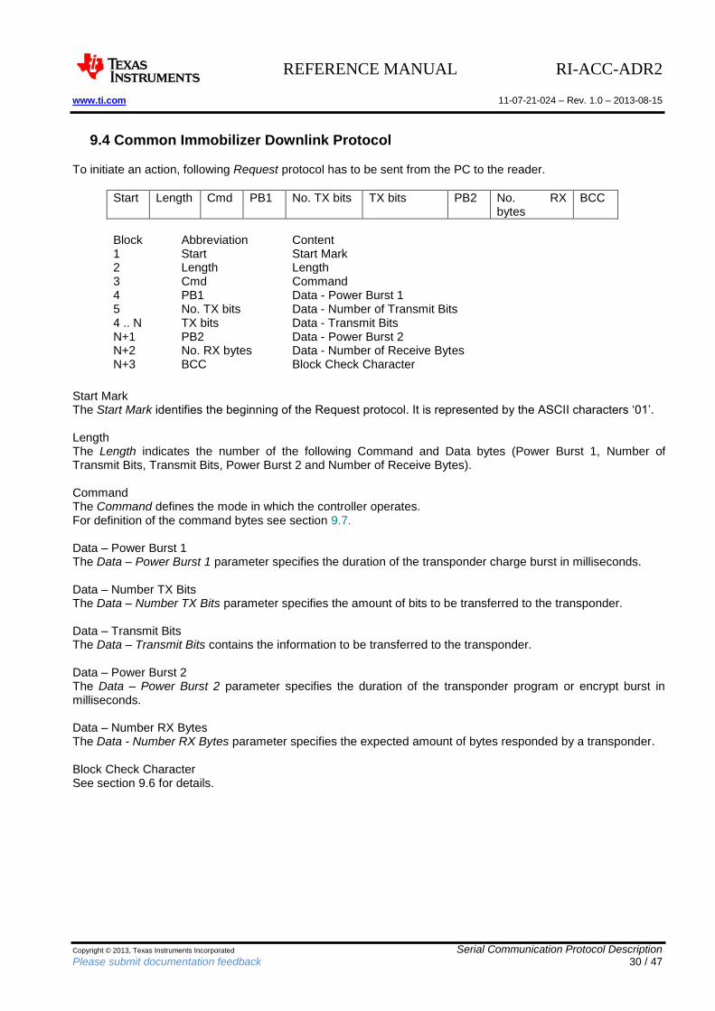
9.4 Common Immobilizer Downlink Protocol
To initiate an action, following Request protocol has to be sent from the PC to the reader.
Start Length Cmd PB1 No. TX bits TX bits PB2 No. RX bytes
BCC
Block Abbreviation Content 1 Start Start Mark 2 Length Length 3 Cmd Command 4 PB1 Data - Power Burst 1 5 No. TX bits Data - Number of Transmit Bits 4 .. N TX bits Data - Transmit Bits N+1 PB2 Data - Power Burst 2 N+2 No. RX bytes Data - Number of Receive Bytes N+3 BCC Block Check Character
Start Mark The Start Mark identifies the beginning of the Request protocol. It is represented by the ASCII characters ‘01’. Length The Length indicates the number of the following Command and Data bytes (Power Burst 1, Number of Transmit Bits, Transmit Bits, Power Burst 2 and Number of Receive Bytes). Command The Command defines the mode in which the controller operates. For definition of the command bytes see section 9.7. Data – Power Burst 1 The Data – Power Burst 1 parameter specifies the duration of the transponder charge burst in milliseconds. Data – Number TX Bits The Data – Number TX Bits parameter specifies the amount of bits to be transferred to the transponder. Data – Transmit Bits The Data – Transmit Bits contains the information to be transferred to the transponder. Data – Power Burst 2 The Data – Power Burst 2 parameter specifies the duration of the transponder program or encrypt burst in milliseconds. Data – Number RX Bytes The Data - Number RX Bytes parameter specifies the expected amount of bytes responded by a transponder. Block Check Character See section 9.6 for details.
REFERENCE MANUAL RI-ACC-ADR2 www.ti.com 11-07-21-024 – Rev. 1.0 – 2013-08-15
Copyright © 2013, Texas Instruments Incorporated Serial Communication Protocol Description Please submit documentation feedback 31 / 47
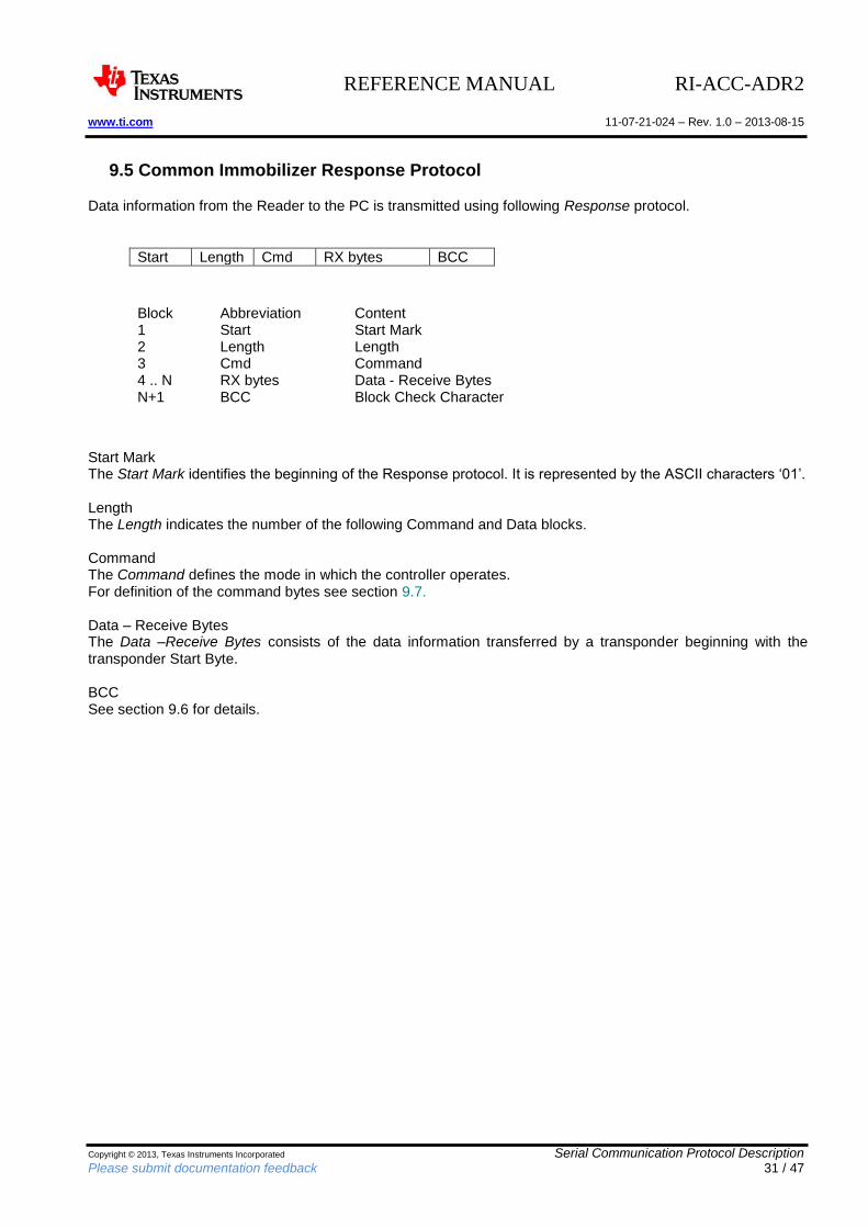
9.5 Common Immobilizer Response Protocol
Data information from the Reader to the PC is transmitted using following Response protocol.
Start Length Cmd RX bytes BCC
Block Abbreviation Content 1 Start Start Mark 2 Length Length 3 Cmd Command 4 .. N RX bytes Data - Receive Bytes N+1 BCC Block Check Character
Start Mark The Start Mark identifies the beginning of the Response protocol. It is represented by the ASCII characters ‘01’. Length The Length indicates the number of the following Command and Data blocks. Command The Command defines the mode in which the controller operates. For definition of the command bytes see section 9.7. Data – Receive Bytes The Data –Receive Bytes consists of the data information transferred by a transponder beginning with the transponder Start Byte. BCC See section 9.6 for details.
REFERENCE MANUAL RI-ACC-ADR2 www.ti.com 11-07-21-024 – Rev. 1.0 – 2013-08-15
Copyright © 2013, Texas Instruments Incorporated Serial Communication Protocol Description Please submit documentation feedback 32 / 47
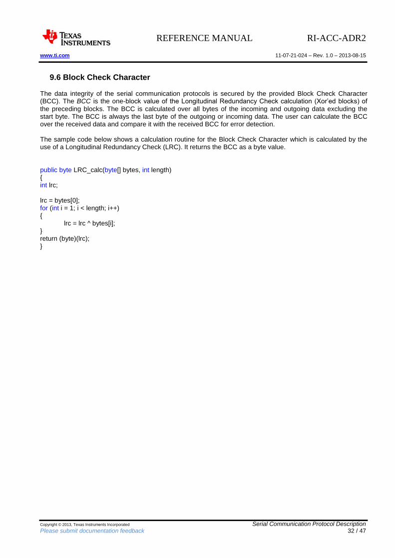
9.6 Block Check Character
The data integrity of the serial communication protocols is secured by the provided Block Check Character (BCC). The BCC is the one-block value of the Longitudinal Redundancy Check calculation (Xor’ed blocks) of the preceding blocks. The BCC is calculated over all bytes of the incoming and outgoing data excluding the start byte. The BCC is always the last byte of the outgoing or incoming data. The user can calculate the BCC over the received data and compare it with the received BCC for error detection. The sample code below shows a calculation routine for the Block Check Character which is calculated by the use of a Longitudinal Redundancy Check (LRC). It returns the BCC as a byte value. public byte LRC_calc(byte[] bytes, int length) { int lrc; lrc = bytes[0]; for (int i = 1; i < length; i++) {
lrc = lrc ^ bytes[i]; } return (byte)(lrc); }
REFERENCE MANUAL RI-ACC-ADR2 www.ti.com 11-07-21-024 – Rev. 1.0 – 2013-08-15
Copyright © 2013, Texas Instruments Incorporated Serial Communication Protocol Description Please submit documentation feedback 33 / 47
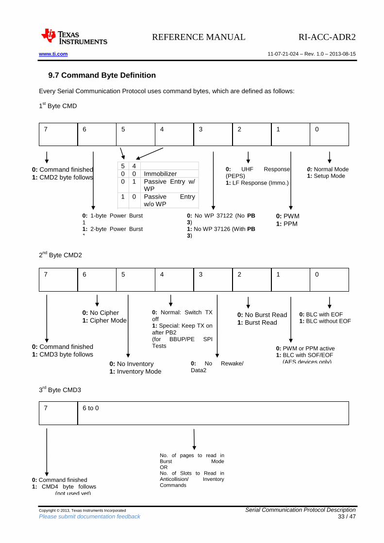
9.7 Command Byte Definition
Every Serial Communication Protocol uses command bytes, which are defined as follows: 1
st Byte CMD
2
nd Byte CMD2
3rd
Byte CMD3
6 5 4 3 2 1 0 7
0: Normal Mode 1: Setup Mode
0: PWM
1: PPM
0: UHF Response
(PEPS)
1: LF Response (Immo.)
0: No WP 37122 (No PB 3) 1: No WP 37126 (With PB 3)
5 4
0 0 Immobilizer
0 1 Passive Entry w/ WP
1 0 Passive Entry w/o WP
1 1 Battery Backup
0: 1-byte Power Burst
1 1: 2-byte Power Burst
1 Ignored for AES PEPS
0: Command finished
1: CMD2 byte follows
6 5 4 3 2 1 0 7
0: BLC with EOF 1: BLC without EOF
0: PWM or PPM active 1: BLC with SOF/EOF
(AES devices only)
0: No Burst Read
1: Burst Read
0: No Cipher
1: Cipher Mode
0: Command finished
1: CMD3 byte follows
0: Normal: Switch TX
off 1: Special: Keep TX on
after PB2 (for BBUP/PE SPI Tests and Advanced LF Commands, e.g. Inventory Process) 0: No Inventory
1: Inventory Mode
0: No Rewake/
Data2 1: Rewake/ Data2
6 to 0 7
0: Command finished 1: CMD4 byte follows
(not used yet)
No. of pages to read in Burst Mode OR No. of Slots to Read in Anticollision/ Inventory Commands
REFERENCE MANUAL RI-ACC-ADR2 www.ti.com 11-07-21-024 – Rev. 1.0 – 2013-08-15
Copyright © 2013, Texas Instruments Incorporated Serial Communication Protocol Description Please submit documentation feedback 34 / 47
9.8 Specific Protocols
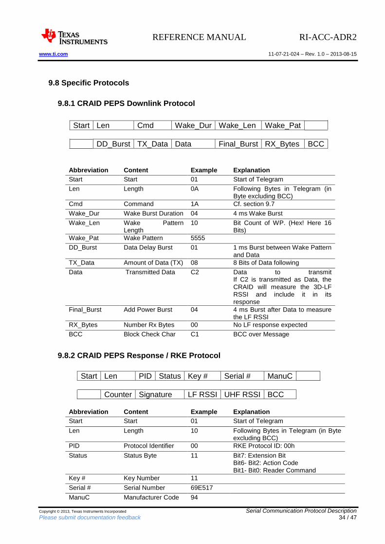
9.8.1 CRAID PEPS Downlink Protocol
Start Len Cmd Wake_Dur Wake_Len Wake_Pat
DD_Burst TX_Data Data Final_Burst RX_Bytes BCC
Abbreviation Content Example Explanation
Start Start 01 Start of Telegram
Len Length 0A Following Bytes in Telegram (in Byte excluding BCC)
Cmd Command 1A Cf. section 9.7
Wake_Dur Wake Burst Duration 04 4 ms Wake Burst
Wake_Len Wake Pattern Length
10 Bit Count of WP. (Hex! Here 16 Bits)
Wake_Pat Wake Pattern 5555
DD_Burst Data Delay Burst 01 1 ms Burst between Wake Pattern and Data
TX_Data Amount of Data (TX) 08 8 Bits of Data following
Data Transmitted Data C2 Data to transmit If C2 is transmitted as Data, the CRAID will measure the 3D-LF RSSI and include it in its response
Final_Burst Add Power Burst 04 4 ms Burst after Data to measure the LF RSSI
RX_Bytes Number Rx Bytes 00 No LF response expected
BCC Block Check Char C1 BCC over Message
9.8.2 CRAID PEPS Response / RKE Protocol
Start Len PID Status Key # Serial # ManuC
Counter Signature LF RSSI UHF RSSI BCC
Abbreviation Content Example Explanation
Start Start 01 Start of Telegram
Len Length 10 Following Bytes in Telegram (in Byte excluding BCC)
PID Protocol Identifier 00 RKE Protocol ID: 00h
Status Status Byte 11 Bit7: Extension Bit Bit6- Bit2: Action Code Bit1- Bit0: Reader Command
Key # Key Number 11
Serial # Serial Number 69E517
ManuC Manufacturer Code 94
REFERENCE MANUAL RI-ACC-ADR2 www.ti.com 11-07-21-024 – Rev. 1.0 – 2013-08-15
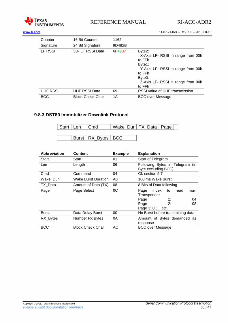
Copyright © 2013, Texas Instruments Incorporated Serial Communication Protocol Description Please submit documentation feedback 35 / 47
Counter 16 Bit Counter 1162
Signature 24 Bit Signature 9D482B
LF RSSI 3D- LF RSSI Data 6F4937 Byte2: X-Axis LF- RSSI in range from 00h to FFh Byte1: Y-Axis LF- RSSI in range from 00h to FFh Byte0: Z-Axis LF- RSSI in range from 00h to FFh
UHF RSSI UHF RSSI Data 69 RSSI value of UHF transmission
BCC Block Check Char 1A BCC over Message
9.8.3 DST80 Immobilizer Downlink Protocol
Start Len Cmd Wake_Dur TX_Data Page
Burst RX_Bytes BCC
Abbreviation Content Example Explanation
Start Start 01 Start of Telegram
Len Length 06 Following Bytes in Telegram (in Byte excluding BCC)
Cmd Command 04 Cf. section 9.7
Wake_Dur Wake Burst Duration A0 160 ms Wake Burst
TX_Data Amount of Data (TX) 08 8 Bits of Data following
Page Page Select 0C Page index to read from Transponder Page 1: 04 Page 2: 08 Page 3: 0C etc.
Burst Data Delay Burst 00 No Burst before transmitting data
RX_Bytes Number Rx Bytes 0A Amount of Bytes demanded as response
BCC Block Check Char AC BCC over Message
REFERENCE MANUAL RI-ACC-ADR2 www.ti.com 11-07-21-024 – Rev. 1.0 – 2013-08-15
Copyright © 2013, Texas Instruments Incorporated Serial Communication Protocol Description Please submit documentation feedback 36 / 47
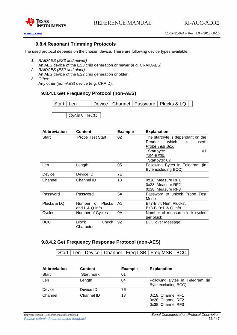
9.8.4 Resonant Trimming Protocols
The used protocol depends on the chosen device. There are following device types available:
1. RAIDAES (ES3 and newer) An AES device of the ES3 chip generation or newer (e.g. CRAIDAES)
2. RAIDAES (ES2 and older) An AES device of the ES2 chip generation or older.
3. Others Any other (non-AES) device (e.g. CRAID).
9.8.4.1 Get Frequency Protocol (non-AES)
Start Len Device Channel Password Plucks & LQ
Cycles BCC
Abbreviation Content Example Explanation
Start Probe Test Start 02 The startbyte is dependant on the Reader which is used: Probe Test Box: Startbyte: 01 TBA-B300: Startbyte: 02
Len Length 05 Following Bytes in Telegram (in Byte excluding BCC)
Device Device ID 7E
Channel Channel ID 18 0x18: Measure RF1 0x28: Measure RF2 0x38: Measure RF3
Password Password 5A Password to unlock Probe Test Mode
Plucks & LQ Number of Plucks and L & Q Info
A1 Bit7-Bit4: Num Plucks\ Bit3-Bit0: L & Q Info
Cycles Number of Cycles 0A Number of measure clock cycles per pluck
BCC Block Check Character
92 BCC over Message
9.8.4.2 Get Frequency Response Protocol (non-AES)
Start Len Device Channel Freq LSB Freq MSB BCC
Abbreviation Content Example Explanation
Start Start mark 01
Len Length 04 Following Bytes in Telegram (in Byte excluding BCC)
Device Device ID 7E
Channel Channel ID 18 0x18: Channel RF1 0x28: Channel RF2 0x38: Channel RF3
REFERENCE MANUAL RI-ACC-ADR2 www.ti.com 11-07-21-024 – Rev. 1.0 – 2013-08-15
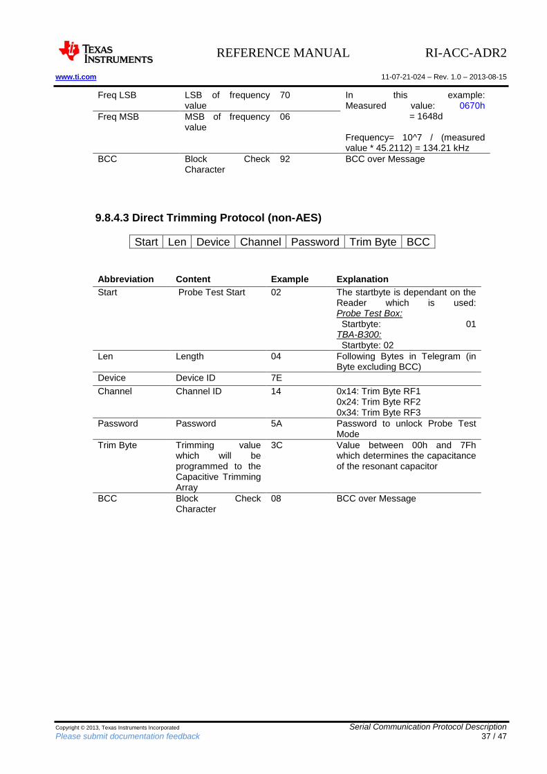
Copyright © 2013, Texas Instruments Incorporated Serial Communication Protocol Description Please submit documentation feedback 37 / 47
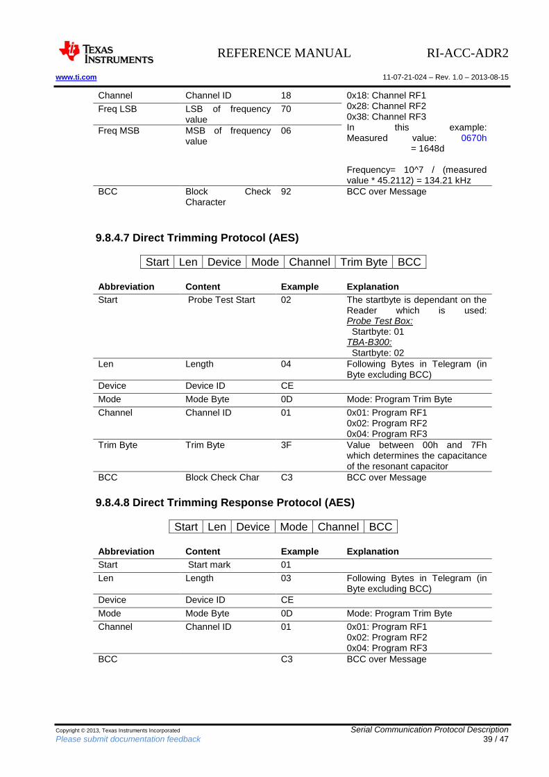
Freq LSB LSB of frequency value
70 In this example: Measured value: 0670h = 1648d Frequency= 10^7 / (measured value * 45.2112) = 134.21 kHz
Freq MSB MSB of frequency value
06
BCC Block Check Character
92 BCC over Message
9.8.4.3 Direct Trimming Protocol (non-AES)
Start Len Device Channel Password Trim Byte BCC
Abbreviation Content Example Explanation
Start Probe Test Start 02 The startbyte is dependant on the Reader which is used: Probe Test Box: Startbyte: 01 TBA-B300: Startbyte: 02
Len Length 04 Following Bytes in Telegram (in Byte excluding BCC)
Device Device ID 7E
Channel Channel ID 14 0x14: Trim Byte RF1 0x24: Trim Byte RF2 0x34: Trim Byte RF3
Password Password 5A Password to unlock Probe Test Mode
Trim Byte Trimming value which will be programmed to the Capacitive Trimming Array
3C Value between 00h and 7Fh which determines the capacitance of the resonant capacitor
BCC Block Check Character
08 BCC over Message
REFERENCE MANUAL RI-ACC-ADR2 www.ti.com 11-07-21-024 – Rev. 1.0 – 2013-08-15
Copyright © 2013, Texas Instruments Incorporated Serial Communication Protocol Description Please submit documentation feedback 38 / 47
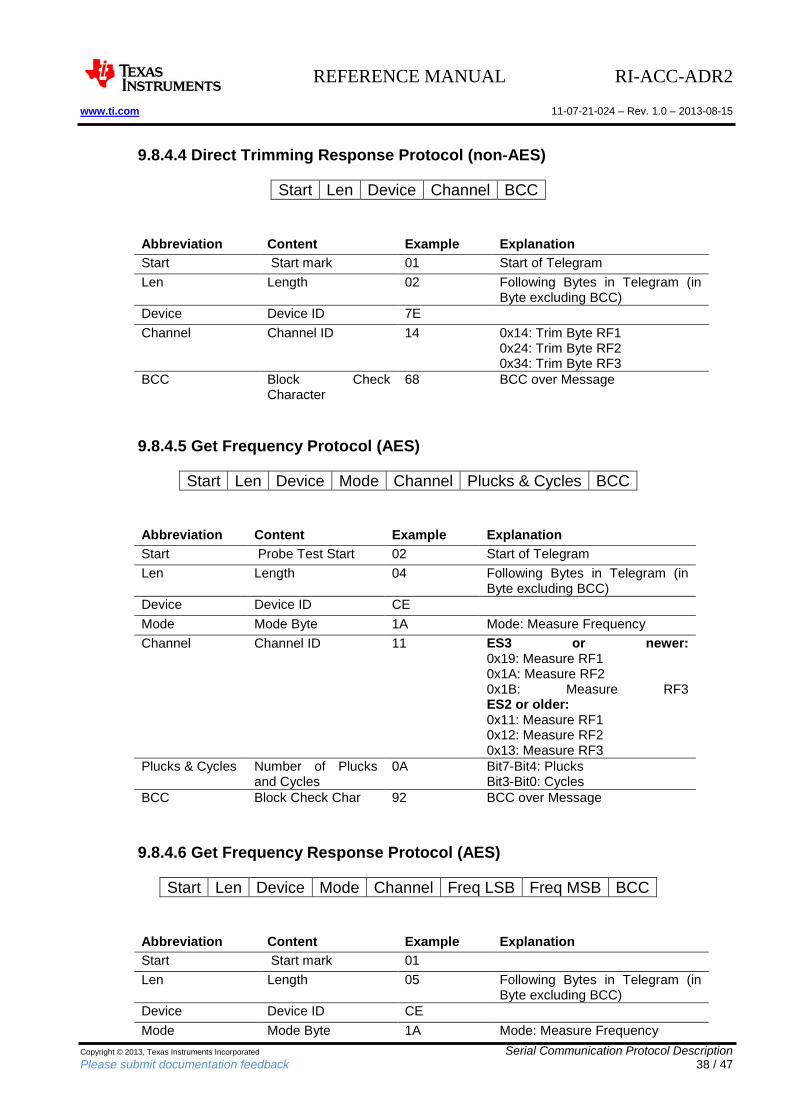
9.8.4.4 Direct Trimming Response Protocol (non-AES)
Start Len Device Channel BCC
Abbreviation Content Example Explanation
Start Start mark 01 Start of Telegram
Len Length 02 Following Bytes in Telegram (in Byte excluding BCC)
Device Device ID 7E
Channel Channel ID 14 0x14: Trim Byte RF1 0x24: Trim Byte RF2 0x34: Trim Byte RF3
BCC Block Check Character
68 BCC over Message
9.8.4.5 Get Frequency Protocol (AES)
Start Len Device Mode Channel Plucks & Cycles BCC
Abbreviation Content Example Explanation
Start Probe Test Start 02 Start of Telegram
Len Length 04 Following Bytes in Telegram (in Byte excluding BCC)
Device Device ID CE
Mode Mode Byte 1A Mode: Measure Frequency
Channel Channel ID 11 ES3 or newer: 0x19: Measure RF1 0x1A: Measure RF2 0x1B: Measure RF3 ES2 or older: 0x11: Measure RF1 0x12: Measure RF2 0x13: Measure RF3
Plucks & Cycles Number of Plucks and Cycles
0A Bit7-Bit4: Plucks Bit3-Bit0: Cycles
BCC Block Check Char 92 BCC over Message
9.8.4.6 Get Frequency Response Protocol (AES)
Start Len Device Mode Channel Freq LSB Freq MSB BCC
Abbreviation Content Example Explanation
Start Start mark 01
Len Length 05 Following Bytes in Telegram (in Byte excluding BCC)
Device Device ID CE
Mode Mode Byte 1A Mode: Measure Frequency
REFERENCE MANUAL RI-ACC-ADR2 www.ti.com 11-07-21-024 – Rev. 1.0 – 2013-08-15
Copyright © 2013, Texas Instruments Incorporated Serial Communication Protocol Description Please submit documentation feedback 39 / 47
Channel Channel ID 18 0x18: Channel RF1 0x28: Channel RF2 0x38: Channel RF3 In this example: Measured value: 0670h = 1648d Frequency= 10^7 / (measured value * 45.2112) = 134.21 kHz
Freq LSB LSB of frequency value
70
Freq MSB MSB of frequency value
06
BCC Block Check Character
92 BCC over Message
9.8.4.7 Direct Trimming Protocol (AES)
Start Len Device Mode Channel Trim Byte BCC
Abbreviation Content Example Explanation
Start Probe Test Start 02 The startbyte is dependant on the Reader which is used: Probe Test Box: Startbyte: 01 TBA-B300: Startbyte: 02
Len Length 04 Following Bytes in Telegram (in Byte excluding BCC)
Device Device ID CE
Mode Mode Byte 0D Mode: Program Trim Byte
Channel Channel ID 01 0x01: Program RF1 0x02: Program RF2 0x04: Program RF3
Trim Byte Trim Byte 3F Value between 00h and 7Fh which determines the capacitance of the resonant capacitor
BCC Block Check Char C3 BCC over Message
9.8.4.8 Direct Trimming Response Protocol (AES)
Start Len Device Mode Channel BCC
Abbreviation Content Example Explanation
Start Start mark 01
Len Length 03 Following Bytes in Telegram (in Byte excluding BCC)
Device Device ID CE
Mode Mode Byte 0D Mode: Program Trim Byte
Channel Channel ID 01 0x01: Program RF1 0x02: Program RF2 0x04: Program RF3
BCC C3 BCC over Message
REFERENCE MANUAL RI-ACC-ADR2 www.ti.com 11-07-21-024 – Rev. 1.0 – 2013-08-15
Copyright © 2013, Texas Instruments Incorporated Serial Communication Protocol Description Please submit documentation feedback 40 / 47
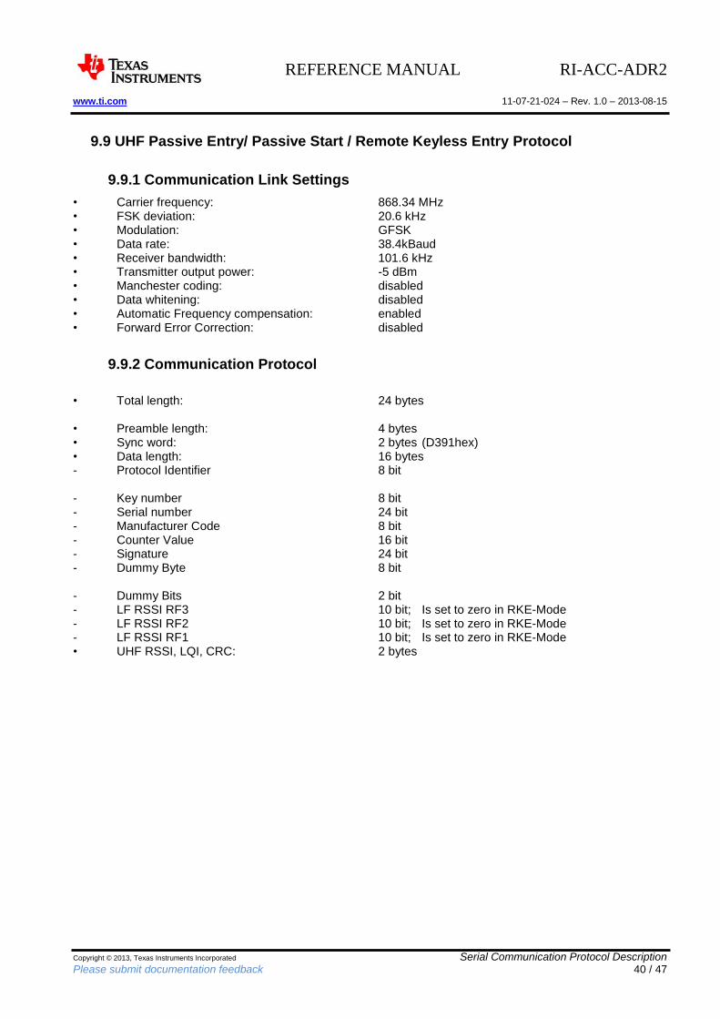
9.9 UHF Passive Entry/ Passive Start / Remote Keyless Entry Protocol
9.9.1 Communication Link Settings
• Carrier frequency: 868.34 MHz • FSK deviation: 20.6 kHz • Modulation: GFSK • Data rate: 38.4kBaud • Receiver bandwidth: 101.6 kHz • Transmitter output power: -5 dBm • Manchester coding: disabled • Data whitening: disabled • Automatic Frequency compensation: enabled • Forward Error Correction: disabled
9.9.2 Communication Protocol
• Total length: 24 bytes • Preamble length: 4 bytes • Sync word: 2 bytes (D391hex) • Data length: 16 bytes - Protocol Identifier 8 bit - Key number 8 bit - Serial number 24 bit - Manufacturer Code 8 bit - Counter Value 16 bit - Signature 24 bit - Dummy Byte 8 bit - Dummy Bits 2 bit - LF RSSI RF3 10 bit; Is set to zero in RKE-Mode - LF RSSI RF2 10 bit; Is set to zero in RKE-Mode - LF RSSI RF1 10 bit; Is set to zero in RKE-Mode • UHF RSSI, LQI, CRC: 2 bytes
REFERENCE MANUAL RI-ACC-ADR2 www.ti.com 11-07-21-024 – Rev. 1.0 – 2013-08-15
Copyright © 2013, Texas Instruments Incorporated EVM Important Notice Please submit documentation feedback 41 / 47
10 EVM Important Notice
10.1 EVALUATION BOARD/KIT/MODULE (EVM) ADDITIONAL TERMS
Texas Instruments (TI) provides the enclosed Evaluation Board/Kit/Module (EVM) under the following conditions: The user assumes all responsibility and liability for proper and safe handling of the goods. Further, the user indemnifies TI from all claims arising from the handling or use of the goods. Please read the User's Guide and, specifically, the Warnings and Restrictions notice in the User's Guide prior to handling the product. This notice contains important safety information about temperatures and voltages. For additional information on TI's environmental and/or safety programs, please visit www.ti.com/esh or contact TI. No license is granted under any patent right or other intellectual property right of TI covering or relating to any machine, process, or combination in which such TI products or services might be or are used. TI currently deals with a variety of customers for products, and therefore our arrangement with the user is not exclusive. TI assumes no liability for applications assistance, customer product design, software performance, or infringement of patents or services described herein. Mailing Address: Texas Instruments Post Office Box 655303 Dallas, Texas 75265 Copyright 2011, Texas Instruments Incorporated
10.2 REGULATORY COMPLIANCE INFORMATION
As noted in the EVM User’s Guide and/or EVM itself, this EVM and/or accompanying hardware may or may not be subject to the Federal Communications Commission (FCC) and Industry Canada (IC) rules For EVMs not subject to the above rules, this evaluation board/kit/module is intended for use for ENGINEERING DEVELOPMENT, DEMONSTRATION OR EVALUATION PURPOSES ONLY and is not considered by TI to be a finished end product fit for general consumer use. It generates, uses, and can radiate radio frequency energy and has not been tested for compliance with the limits of computing devices pursuant to part 15 of FCC or ICES-003 rules, which are designed to provide reasonable protection against radio frequency interference. Operation of the equipment may cause interference with radio communications, in which case the user at his own expense will be required to take whatever measures may be required to correct this interference. General Statement for EVMs including a radio User Power/Frequency Use Obligations: This radio is intended for development/professional use only in legally allocated frequency and power limits. Any use of radio frequencies and/or power availability of this EVM and its development application(s) must comply with local laws governing radio spectrum allocation and power limits for this evaluation module. It is the user's sole responsibility to only operate this radio in legally acceptable frequency space and within legally mandated power limitations. Any exceptions to this is strictly prohibited and unauthorized by Texas Instruments unless user has obtained appropriate experimental/development licenses from local regulatory authorities, which is responsibility of user including its acceptable authorization. For EVMs annotated as FCC – FEDERAL COMMUNICATIONS COMMISSION Part 15 Compliant Caution This device complies with part 15 of the FCC Rules. Operation is subject to the following two conditions: (1) This device may not cause harmful interference, and (2) this device must accept any interference received, including interference that may cause undesired operation.
REFERENCE MANUAL RI-ACC-ADR2 www.ti.com 11-07-21-024 – Rev. 1.0 – 2013-08-15
Copyright © 2013, Texas Instruments Incorporated EVM Important Notice Please submit documentation feedback 42 / 47
Changes or modifications not expressly approved by the party responsible for compliance could void the user's authority to operate the equipment. FCC Interference Statement for Class A EVM devices This equipment has been tested and found to comply with the limits for a Class A digital device, pursuant to part 15 of the FCC Rules. These limits are designed to provide reasonable protection against harmful interference when the equipment is operated in a commercial environment. This equipment generates, uses, and can radiate radio frequency energy and, if not installed and used in accordance with the instruction manual, may cause harmful interference to radio communications. Operation of this equipment in a residential area is likely to cause harmful interference in which case the user will be required to correct the interference at his own expense. FCC Interference Statement for Class B EVM devices This equipment has been tested and found to comply with the limits for a Class B digital device, pursuant to part 15 of the FCC Rules. These limits are designed to provide reasonable protection against harmful interference in a residential installation. This equipment generates, uses and can radiate radio frequency energy and, if not installed and used in accordance with the instructions, may cause harmful interference to radio communications. However, there is no guarantee that interference will not occur in a particular installation. If this equipment does cause harmful interference to radio or television reception, which can be determined by turning the equipment off and on, the user is encouraged to try to correct the interference by one or more of the following measures:
Reorient or relocate the receiving antenna.
Increase the separation between the equipment and receiver.
Connect the equipment into an outlet on a circuit different from that to which the receiver is connected.
Consult the dealer or an experienced radio/TV technician for help. For EVMs annotated as IC – INDUSTRY CANADA Compliant This Class A or B digital apparatus complies with Canadian ICES-003. Changes or modifications not expressly approved by the party responsible for compliance could void the user's authority to operate the equipment. Concerning EVMs including radio transmitters This device complies with Industry Canada licence-exempt RSS standard(s). Operation is subject to the following two conditions: (1) this device may not cause interference, and (2) this device must accept any interference, including interference that may cause undesired operation of the device. Concerning EVMs including detachable antennas Under Industry Canada regulations, this radio transmitter may only operate using an antenna of a type and maximum (or lesser) gain approved for the transmitter by Industry Canada. To reduce potential radio interference to other users, the antenna type and its gain should be so chosen that the equivalent isotropically radiated power (e.i.r.p.) is not more than that necessary for successful communication. This radio transmitter has been approved by Industry Canada to operate with the antenna types listed in the user guide with the maximum permissible gain and required antenna impedance for each antenna type indicated. Antenna types not included in this list, having a gain greater than the maximum gain indicated for that type, are strictly prohibited for use with this device. Cet appareil numérique de la classe A ou B est conforme à la norme NMB-003 du Canada. Les changements ou les modifications pas expressément approuvés par la partie responsable de la conformité ont pu vider l'autorité de l'utilisateur pour actionner l'équipement.
REFERENCE MANUAL RI-ACC-ADR2 www.ti.com 11-07-21-024 – Rev. 1.0 – 2013-08-15
Copyright © 2013, Texas Instruments Incorporated EVM Important Notice Please submit documentation feedback 43 / 47
Concernant les EVMs avec appareils radio Le présent appareil est conforme aux CNR d'Industrie Canada applicables aux appareils radio exempts de licence. L'exploitation est autorisée aux deux conditions suivantes : (1) l'appareil ne doit pas produire de brouillage, et (2) l'utilisateur de l'appareil doit accepter tout brouillage radioélectrique subi, même si le brouillage est susceptible d'en compromettre le fonctionnement. Concernant les EVMs avec antennes détachables Conformément à la réglementation d'Industrie Canada, le présent émetteur radio peut fonctionner avec une antenne d'un type et d'un gain maximal (ou inférieur) approuvé pour l'émetteur par Industrie Canada. Dans le but de réduire les risques de brouillage radioélectrique à l'intention des autres utilisateurs, il faut choisir le type d'antenne et son gain de sorte que la puissance isotrope rayonnée équivalente (p.i.r.e.) ne dépasse pas l'intensité nécessaire à l'établissement d'une communication satisfaisante. Le présent émetteur radio a été approuvé par Industrie Canada pour fonctionner avec les types d'antenne énumérés dans le manuel d'usage et ayant un gain admissible maximal et l'impédance requise pour chaque type d'antenne. Les types d'antenne non inclus dans cette liste, ou dont le gain est supérieur au gain maximal indiqué, sont strictement interdits pour l'exploitation de l'émetteur.
10.3 Important Notice for Users of this Product in Japan
This development kit is NOT certified as Confirming to Technical Regulations of Radio Law of Japan! If you use this product in Japan, you are required by Radio Law of Japan to follow the instructions below with respect to this product: Use this product in a shielded room or any other test facility as defined in the notification \#173 issued by Ministry of Internal Affairs and Communications on March 28, 2006, based on Sub-section 1.1 of Article 6 of the Ministry's Rule for Enforcement of Radio Law of Japan, Use this product only after you obtained the license of Test Radio Station as provided in Radio Law of Japan with respect to this product, or Use of this product only after you obtained the Technical Regulations Conformity Certification as provided in Radio Law of Japan with respect to this product. Also, please do not transfer this product, unless you give the same notice above to the transferee. Please note that if you could not follow the instructions above, you will be subject to penalties of Radio Law of Japan. Texas Instruments Japan Limited (address) 24-1, Nishi-Shinjuku 6 chome, Shinjukku-ku, Tokyo, Japan http://www.tij.co.jp
ご使用にあたっての注意
本開発キットは技術基準適合証明を受けておりません。
本製品のご使用に際しては、電波法遵守のため、以下のいずれかの措置を取っていただく必要がありますので
ご注意ください。
(1)電波法施行規則第6条第1項第1号に基づく平成18年3月28日総務省告示第173号で定められた電波暗室等
の試験設備でご使用いただく。
(2)実験局の免許を取得後ご使用いただく。
(3)技術基準適合証明を取得後ご使用いただく。
なお、本製品は、上記の「ご使用にあたっての注意」を譲渡先、移転先に通知しない限り、譲渡、移転できな
いものとします。
REFERENCE MANUAL RI-ACC-ADR2 www.ti.com 11-07-21-024 – Rev. 1.0 – 2013-08-15
Copyright © 2013, Texas Instruments Incorporated EVM Important Notice Please submit documentation feedback 44 / 47
上記を遵守頂けない場合は、電波法の罰則が適用される可能性があることをご留意ください。
日本テキサス・インスツルメンツ株式会社
東京都新宿区西新宿6丁目24番1号
西新宿三井ビル
http://www.tij.co.jp
10.4 EVALUATION BOARD/KIT/MODULE (EVM)WARNINGS, RESTRICTIONS AND DISCLAIMERS
For Feasibility Evaluation Only, in Laboratory/Development Environments. Unless otherwise indicated, this EVM is not a finished electrical equipment and not intended for consumer use. It is intended solely for use for preliminary feasibility evaluation in laboratory/development environments by technically qualified electronics experts who are familiar with the dangers and application risks associated with handling electrical mechanical components, systems and subsystems. It should not be used as all or part of a finished end product. Your Sole Responsibility and Risk. You acknowledge, represent and agree that:
1. You have unique knowledge concerning Federal, State and local regulatory requirements (including but not limited to Food and Drug Administration regulations, if applicable) which relate to your products and which relate to your use (and/or that of your employees, affiliates, contractors or designees) of the EVM for evaluation, testing and other purposes.
2. You have full and exclusive responsibility to assure the safety and compliance of your products with all such laws and other applicable regulatory requirements, and also to assure the safety of any activities to be conducted by you and/or your employees, affiliates, contractors or designees, using the EVM. Further, you are responsible to assure that any interfaces (electronic and/or mechanical) between the EVM and any human body are designed with suitable isolation and means to safely limit accessible leakage currents to minimize the risk of electrical shock hazard.
3. You will employ reasonable safeguards to ensure that your use of the EVM will not result in any property damage, injury or death, even if the EVM should fail to perform as described or expected.
4. You will take care of proper disposal and recycling of the EVM's electronic components and packing materials
Certain Instructions. It is important to operate this EVM within TI’s recommended specifications and environmental considerations per the user guidelines. Exceeding the specified EVM ratings (including but not limited to input and output voltage, current, power, and environmental ranges) may cause property damage, personal injury or death. If there are questions concerning these ratings please contact a TI field representative prior to connecting interface electronics including input power and intended loads. Any loads applied outside of the specified output range may result in unintended and/or inaccurate operation and/or possible permanent damage to the EVM and/or interface electronics. Please consult the EVM User's Guide prior to connecting any load to the EVM output. If there is uncertainty as to the load specification, please contact a TI field representative. During normal operation, some circuit components may have case temperatures greater than 60°C as long as the input and output are maintained at a normal ambient operating temperature. These components include but are not limited to linear regulators, switching transistors, pass transistors, and current sense resistors which can be identified using the EVM schematic located in the EVM User's Guide. When placing measurement probes near these devices during normal operation, please be aware that these devices may be very warm to the touch. As with all electronic evaluation tools, only qualified personnel knowledgeable in electronic measurement and diagnostics normally found in development environments should use these EVMs. Agreement to Defend, Indemnify and Hold Harmless. You agree to defend, indemnify and hold TI, its licensors and their representatives harmless from and against any and all claims, damages, losses, expenses, costs and liabilities (collectively, "Claims") arising out of or in connection with any use of the EVM that is not in
REFERENCE MANUAL RI-ACC-ADR2 www.ti.com 11-07-21-024 – Rev. 1.0 – 2013-08-15
Copyright © 2013, Texas Instruments Incorporated EVM Important Notice Please submit documentation feedback 45 / 47
accordance with the terms of the agreement. This obligation shall apply whether Claims arise under law of tort or contract or any other legal theory, and even if the EVM fails to perform as described or expected. Safety-Critical or Life-Critical Applications. If you intend to evaluate the components for possible use in safety critical applications (such as life support) where a failure of the TI product would reasonably be expected to cause severe personal injury or death, such as devices which are classified as FDA Class III or similar classification, then you must specifically notify TI of such intent and enter into a separate Assurance and Indemnity Agreement.
REFERENCE MANUAL RI-ACC-ADR2 www.ti.com 11-07-21-024 – Rev. 1.0 – 2013-08-15
Copyright © 2013, Texas Instruments Incorporated Revision History Please submit documentation feedback 46 / 47
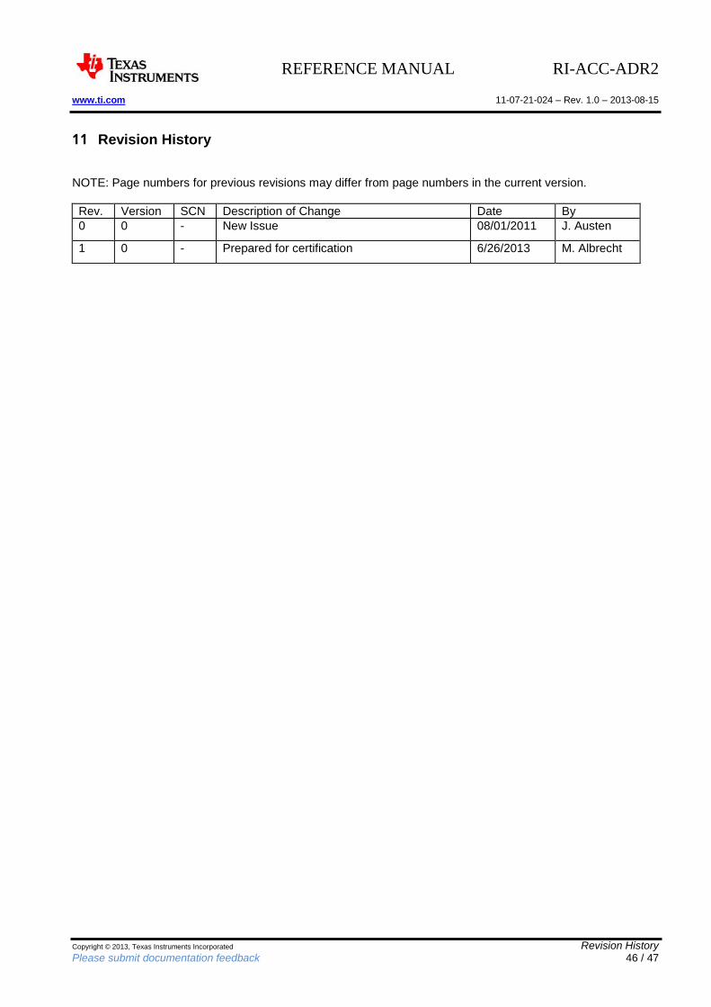
11 Revision History
NOTE: Page numbers for previous revisions may differ from page numbers in the current version.
Rev. Version SCN Description of Change Date By
0 0 - New Issue 08/01/2011 J. Austen
1 0 - Prepared for certification 6/26/2013 M. Albrecht
REFERENCE MANUAL RI-ACC-ADR2 www.ti.com 11-07-21-024 – Rev. 1.0 – 2013-08-15
Copyright © 2013, Texas Instruments Incorporated Revision History Please submit documentation feedback 47 / 47
IMPORTANT NOTICE Texas Instruments Incorporated and its subsidiaries (TI) reserve the right to make corrections, modifications, enhancements, improvements, and other changes to its products and services at any time and to discontinue any product or service without notice. Customers should obtain the latest relevant information before placing orders and should verify that such information is current and complete. All products are sold subject to TI’s terms and conditions of sale supplied at the time of order acknowledgment. TI warrants performance of its hardware products to the specifications applicable at the time of sale in accordance with TI’s standard warranty. Testing and other quality control techniques are used to the extent TI deems necessary to support this warranty. Except where mandated by government requirements, testing of all parameters of each product is not necessarily performed. TI assumes no liability for applications assistance or customer product design. Customers are responsible for their products and applications using TI components. To minimize the risks associated with customer products and applications, customers should provide adequate design and operating safeguards. TI does not warrant or represent that any license, either express or implied, is granted under any TI patent right, copyright, mask work right, or other TI intellectual property right relating to any combination, machine, or process in which TI products or services are used. Information published by TI regarding third-party products or services does not constitute a license from TI to use such products or services or a warranty or endorsement thereof. Use of such information may require a license from a third party under the patents or other intellectual property of the third party, or a license from TI under the patents or other intellectual property of TI. Reproduction of TI information in TI data books or data sheets is permissible only if reproduction is without alteration and is accompanied by all associated warranties, conditions, limitations, and notices. Reproduction of this information with alteration is an unfair and deceptive business practice. TI is not responsible or liable for such altered documentation. Information of third parties may be subject to additional restrictions. Resale of TI products or services with statements different from or beyond the parameters stated by TI for that product or service voids all express and any implied warranties for the associated TI product or service and is an unfair and deceptive business practice. TI is not responsible or liable for any such statements. TI products are not authorized for use in safety-critical applications (such as life support) where a failure of the TI product would reasonably be expected to cause severe personal injury or death, unless officers of the parties have executed an agreement specifically governing such use. Buyers represent that they have all necessary expertise in the safety and regulatory ramifications of their applications, and acknowledge and agree that they are solely responsible for all legal, regulatory and safety-related requirements concerning their products and any use of TI products in such safety-critical applications, notwithstanding any applications-related information or support that may be provided by TI. Further, Buyers must fully indemnify TI and its representatives against any damages arising out of the use of TI products in such safety-critical applications. TI products are neither designed nor intended for use in military/aerospace applications or environments unless the TI products are specifically designated by TI as military-grade or "enhanced plastic." Only products designated by TI as military-grade meet military specifications. Buyers acknowledge and agree that any such use of TI products which TI has not designated as military-grade is solely at the Buyer's risk, and that they are solely responsible for compliance with all legal and regulatory requirements in connection with such use. TI products are neither designed nor intended for use in automotive applications or environments unless the specific TI products are designated by TI as compliant with ISO/TS 16949 requirements. Buyers acknowledge and agree that, if they use any non-designated products in automotive applications, TI will not be responsible for any failure to meet such requirements. Following are URLs where you can obtain information on other Texas Instruments products and application solutions: Products Applications Amplifiers amplifier.ti.com Audio www.ti.com/audio Data Converters dataconverter.ti.com Automotive www.ti.com/automotive DLP® Products www.dlp.com Broadband www.ti.com/broadband DSP dsp.ti.com Digital Control www.ti.com/digitalcontrol Clocks and Timers www.ti.com/clocks Medical www.ti.com/medical Interface interface.ti.com Military www.ti.com/military Logic logic.ti.com Optical Networking www.ti.com/opticalnetwork Power Mgmt power.ti.com Security www.ti.com/security Microcontrollers microcontroller.ti.com Telephony www.ti.com/telephony MCU RF / RFID http://www.ti.com/rfid/ Video & Imaging www.ti.com/video RF/IF and ZigBee® Solutions www.ti.com/lprf Wireless www.ti.com/wireless Mailing Address: Texas Instruments, Post Office Box 655303, Dallas, Texas 75265 Copyright © 2013, Texas Instruments Incorporated


![interoperability.blob.core.windows.net · Web view[MS-ADR2]: Access Services Data Run Time Protocol Version 2. Intellectual Property Rights Notice for Open Specifications Documentation](https://img.pdfslide.us/doc/110x75/5f6e95afda11963bad2f42f3/web-view-ms-adr2-access-services-data-run-time-protocol-version-2-intellectual.jpg)


![Microsoft · Web view[MS-ADR2]: Access Services Data Run Time Protocol Version 2. Intellectual Property Rights Notice for Open Specifications Documentation. Technical Documentation](https://img.pdfslide.us/doc/110x75/5fe34c6641adfa3d80253025/microsoft-web-view-ms-adr2-access-services-data-run-time-protocol-version-2.jpg)