Embed Size (px)
Citation preview
Rhythm Turn
1
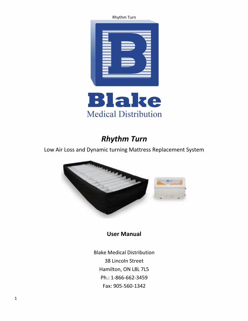
Rhythm Turn Low Air Loss and Dynamic turning Mattress Replacement System
User Manual
Blake Medical Distribution
38 Lincoln Street
Hamilton, ON L8L 7L5
Ph.: 1-866-662-3459
Fax: 905-560-1342

Rhythm Turn
2
Content
1. The Purpose of this Manual
2. Product Description
Master Control Unit Features
Mattress Features
3. Technical Data
Master Control Unit
Rhythm Turn Mattress Replacement
Symbol Definition
4. Instruction for Proper Use
5. Cleaning
The Mattress
The Master Control Unit
Replace Air Filter
Waste Disposal
6. Storage and Care
7. Maintenance
8. EMC Related Notification
9. Warranty

Rhythm Turn
3
Warning
Connect the Master Control unit to a proper power source
Don’t use the system in the presence of any flammable gases (such as Anesthetic agents)
Keep the pump and mattress away from any source of liquid or open flame
Keep mattress away from sharp object
The device is not AP/APG protected
Don’t place the heating device close to the mattress system
Caution
Use the mattress under the physician’s instruction
Re-position the patient in certain period of time is still necessary when using this system
The Control Unit can only be repaired by authorized distributor. (The circuit diagram, repairable component parts list, and service manual are released only to an authorized distributor)
Do not drop the control unit
Do not store the system in direct sunlight or extreme cold conditions
Rhythm Turn
4
1. Purpose of this Manual
This operation manual is mainly focused on the set up, cleaning and routine maintenance of the Rhythm Turn-Function
Air Therapy Support System. We recommend you keeping this manual handy to answer most of your questions related
to this system.
2. Product Description
The Rhythm Turn system, operated blower unit, is a very unique innovation of a specialized mattress replacement. The
system is primarily designed for at risk patients or step-down intensive care units. It features continuous lateral rotation
therapy in two different degrees (20 degrees and 40 degrees), which gently turns the patient from side to side to
significantly lower the risk of infection, pneumonia and other pulmonary complications – illnesses that significantly ad to
patient care costs and length of stay.
Master Control Unit Features
The Master Control Unit is user friendly designed and most of the functions are self explained
Rotation angle can be independently selected for 20 degrees or 40 degrees
Rotation time can be adjusted in 3 min increments to 95 mins. Or the caregiver can even select the Static
Function that will seize the Rotation Function and provide only the True Low Air Loss Therapy
Auto Firm Function provides a uniform firmness for nursing procedure
Power failures produce an audio alarm for added safety
10 digital scales of Soft/Firm Comfort Control
Double insulation to provide minimum noise while operating
Foot board mounting rack provides the convenience of placement.
Mattress Features
Individual air cushion design for maximum pressure distribution
Each air cushion has orifices to provide true Low Air Loss therapy
LAL Turning Mattress replacement, eliminating the compromising effects of an existing mattress
Permanent inflated bed rails for added safety.

Rhythm Turn
5
3. Technical Data
Master Control Unit
Model Name Rhythm Turn
Model No. FC-PHR0010
Size(cm) 45(L) x 17.3 (W) x 27.5(H)
Weight (kg) 5.8
Dwell time 3 ~ 95
Max Operating Pressure 61mmHg
Rated voltage AC 110-120V
Rated frequency 60 Hz
Max current 5A
Fuse rating 5A 250V
Classification Class I, Type BF
Not AP or AGP type
Operation temperature 15oC - 35
oC
Operation humidity 30% -75%
Mode of operation Continuous
Standard IEC 60601-1
CAN/CSA C22.2 No. 601.1,
IEC 60601-1-2
Rhythm Turn Replacement
Model No. FM-PHR0013
Size(cm) 91(L) x 203(W) x 20(H)
Weight (kg) 20
Cell Material TPU
Cover Material AD with Quilting
Based Material Nylon laminated PVC
Symbol Definition
Refer to Accompanying Document
Waste Disposal
Type BF Applied Part
Alternating current
Warning
Rhythm Turn
6
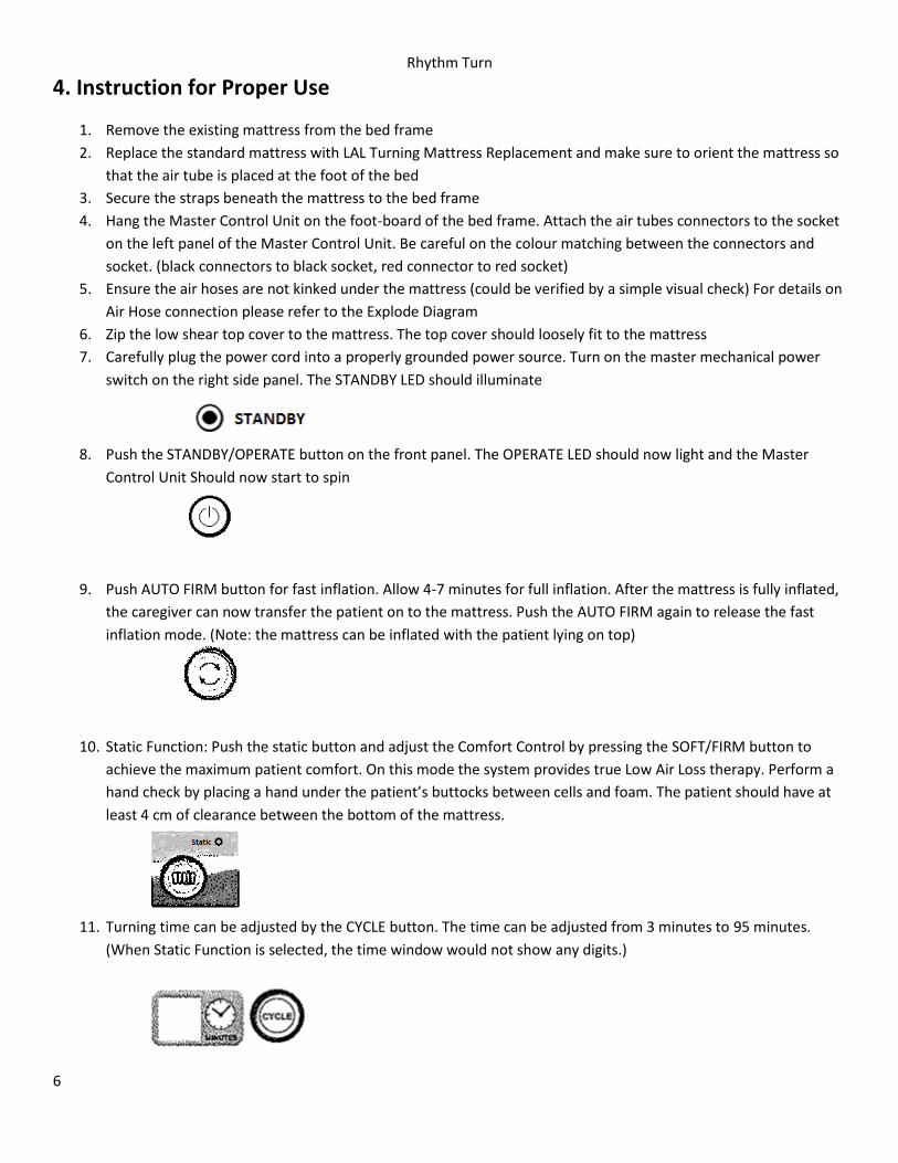
4. Instruction for Proper Use
1. Remove the existing mattress from the bed frame
2. Replace the standard mattress with LAL Turning Mattress Replacement and make sure to orient the mattress so
that the air tube is placed at the foot of the bed
3. Secure the straps beneath the mattress to the bed frame
4. Hang the Master Control Unit on the foot-board of the bed frame. Attach the air tubes connectors to the socket
on the left panel of the Master Control Unit. Be careful on the colour matching between the connectors and
socket. (black connectors to black socket, red connector to red socket)
5. Ensure the air hoses are not kinked under the mattress (could be verified by a simple visual check) For details on
Air Hose connection please refer to the Explode Diagram
6. Zip the low shear top cover to the mattress. The top cover should loosely fit to the mattress
7. Carefully plug the power cord into a properly grounded power source. Turn on the master mechanical power
switch on the right side panel. The STANDBY LED should illuminate
8. Push the STANDBY/OPERATE button on the front panel. The OPERATE LED should now light and the Master
Control Unit Should now start to spin
9. Push AUTO FIRM button for fast inflation. Allow 4-7 minutes for full inflation. After the mattress is fully inflated,
the caregiver can now transfer the patient on to the mattress. Push the AUTO FIRM again to release the fast
inflation mode. (Note: the mattress can be inflated with the patient lying on top)
10. Static Function: Push the static button and adjust the Comfort Control by pressing the SOFT/FIRM button to
achieve the maximum patient comfort. On this mode the system provides true Low Air Loss therapy. Perform a
hand check by placing a hand under the patient’s buttocks between cells and foam. The patient should have at
least 4 cm of clearance between the bottom of the mattress.
11. Turning time can be adjusted by the CYCLE button. The time can be adjusted from 3 minutes to 95 minutes.
(When Static Function is selected, the time window would not show any digits.)

Rhythm Turn
7
12. The Master control unit is equipped with power failure alarm. With this function enabled, the control unit
generates a horn sound to signal to the operator that the main power has failed. The alarm can be disabled by
pushing the alarm reset button on the front panel.
CAUTION: Immediate response by the operator is required with the power failure alarm
13. LOCK-OUT: The Master Control Unit is also equipped with a manual locking-out function. All function keys will
be automatically disabled if the LOCK-OUT button has not been touched. When lock-out has been engaged, the
“LOCK-OUT” button will illuminate.
UNLOCKING: Unlocking the control panel is easy. Simply press the “LOCK OUT” button on the control panel for
3-5 seconds or recycle the power by turning it off and on by the main power switch.
14. 20 degrees turning function can be activated by pressing the TURN and select desired turning therapy, LEFT
TURN allows the mattress to turn left and back to horizontal. RIGHT TURN would have the same affect but
turning to the right. The FULLY TURN allows for full function of turning to left and right and should always
activated with timer setting. The timer can be set by CYCLE button
15. 40 Degrees turning function can be activated by pressing the BT button and follow the operation instruction on
step 14.

Rhythm Turn
8
Mattress Turning Illustration

Rhythm Turn
9
5. Cleaning The Mattress
The mattress should be cleaned on the bed weekly using a damp soft cloth and mild detergent.
If the top sheet (top cover) or base (bottom cover) becomes overly soiled, put on clean gloves, plastic gown and eye
protection before removing top sheet or base and dispose of according to standard in function control procedures.
Replace with clean covers. Covers can be washed and thermally disinfected in a washing machine following below
procedure: (Never use phenol based cleaning solutions)
Industrial cleaning
Break wash cold 10 mins
Main wash 60 C 6 mins
Main wash 72 C 10 mins
Extraction 2 mins
3 cold rinses
Extraction 5 mins
Domestic cleaning
Pre-wash cold
Main wash 72 C 10mins
Extraction 2 mins
Cold Rinses
Extraction 5 mins
Tumble Drying or Tunnel Drying is not recommended.
Mattress cells can be wiped over with a solution of sodium hypochlorite 1000ppm or any other non-phenolic germicidal
solution.
The Master Control Unit
The master control unit should also be cleaned weekly using a damp soft cloth and mild detergent.
The pump casing is manufactured from ABS plastic and if the case is soiled the pump can be wiped down with a sodium
hypochlorite solution to dilution of 1000ppm or any EPA-approved hospital grade disinfectant. (Don’t use phenol based
cleaning solution)
The air filter should also be cleaned and check as often as possible at a minimum of every six months. The air filter can
be removed by punching the centre of the filter and pulling it outward from the back of the Therapy control unit.
CAUTION SWITCH OFF THE ELECTRICAL SUPPLY TO THE PUMP AND DISCONNECT THE POWER CORD FROM MAIN SUPPLY
BEFORE CLEANING AND INSPECTION
Rhythm Turn
10
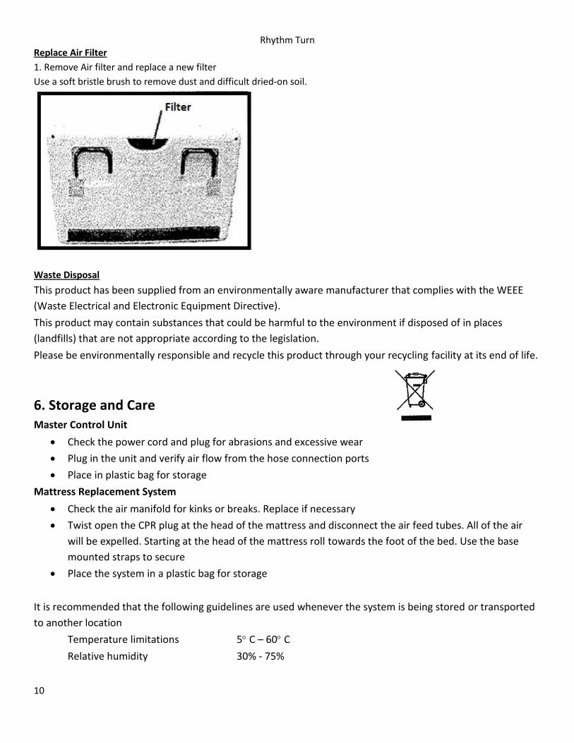
Replace Air Filter
1. Remove Air filter and replace a new filter
Use a soft bristle brush to remove dust and difficult dried-on soil.
Waste Disposal
This product has been supplied from an environmentally aware manufacturer that complies with the WEEE
(Waste Electrical and Electronic Equipment Directive).
This product may contain substances that could be harmful to the environment if disposed of in places
(landfills) that are not appropriate according to the legislation.
Please be environmentally responsible and recycle this product through your recycling facility at its end of life.
6. Storage and Care Master Control Unit
Check the power cord and plug for abrasions and excessive wear
Plug in the unit and verify air flow from the hose connection ports
Place in plastic bag for storage
Mattress Replacement System
Check the air manifold for kinks or breaks. Replace if necessary
Twist open the CPR plug at the head of the mattress and disconnect the air feed tubes. All of the air
will be expelled. Starting at the head of the mattress roll towards the foot of the bed. Use the base
mounted straps to secure
Place the system in a plastic bag for storage
It is recommended that the following guidelines are used whenever the system is being stored or transported
to another location
Temperature limitations 5 C – 60 C
Relative humidity 30% - 75%
Rhythm Turn
11
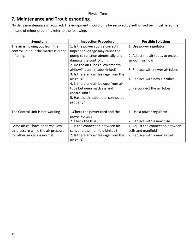
7. Maintenance and Troubleshooting No daily maintenance is required. The equipment should only be serviced by authorized technical personnel.
In case of minor problems refer to the following.
Symptom Inspection Procedure Possible Solutions
The air is flowing out from the control unit but the mattress is not inflating.
1. Is the power source correct? Improper voltage may cause the pump to function abnormally and damage the control unit 2. Do the air tubes allow smooth airflow? Is an air tube kinked? 3. Is there any air leakage from the air cells? 4. Is there any air leakage from air tube between mattress and control unit? 5. Has the air tube been connected properly?
1. Use power regulator 2. Adjust the air tubes to enable smooth air flow 3. Replace with newer air tubes 4. Replace with new air tubes 5. Re-connect the air tubes.
The Control Unit is not working 1.Check the power cord and the power voltage 2. Check the fuse
1. Use a power regulator 2. Replace with a new fuse
Some air cell have abnormal low air pressure while the air pressure for other air cells is normal.
1. Is the connection between air cells and the manifold kinked? 2. Is there any air leakage from the air cells?
1. Adjust the connection between cells and manifold 2. Replace with a new air cell
Rhythm Turn
12
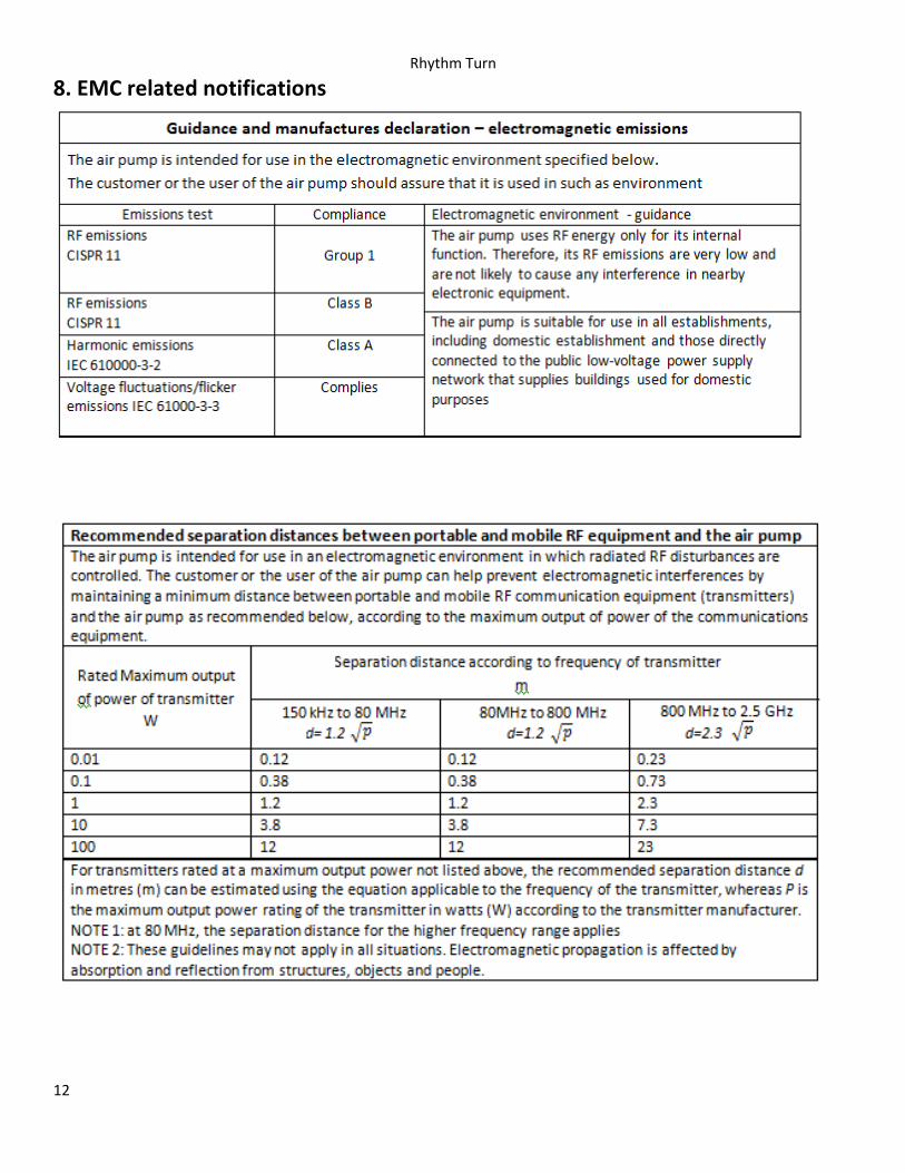
8. EMC related notifications
Rhythm Turn
13
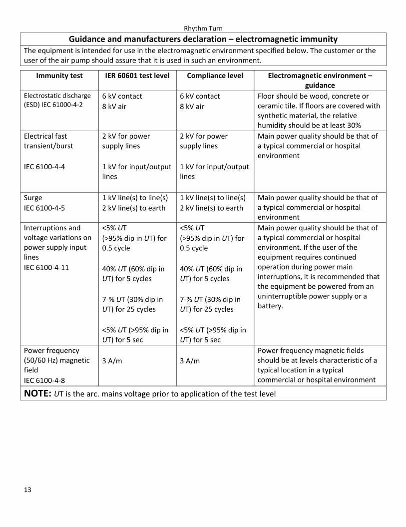
Guidance and manufacturers declaration – electromagnetic immunity The equipment is intended for use in the electromagnetic environment specified below. The customer or the user of the air pump should assure that it is used in such an environment.
NOTE: UT is the arc. mains voltage prior to application of the test level
Immunity test IER 60601 test level Compliance level Electromagnetic environment – guidance
Electrostatic discharge (ESD) IEC 61000-4-2
6 kV contact
8 kV air
6 kV contact
8 kV air
Floor should be wood, concrete or ceramic tile. If floors are covered with synthetic material, the relative humidity should be at least 30%
Electrical fast transient/burst
IEC 6100-4-4
2 kV for power supply lines
1 kV for input/output lines
2 kV for power supply lines
1 kV for input/output lines
Main power quality should be that of a typical commercial or hospital environment
Surge
IEC 6100-4-5
1 kV line(s) to line(s)
2 kV line(s) to earth
1 kV line(s) to line(s)
2 kV line(s) to earth
Main power quality should be that of a typical commercial or hospital environment
Interruptions and voltage variations on power supply input lines
IEC 6100-4-11
<5% UT
(>95% dip in UT) for 0.5 cycle
40% UT (60% dip in UT) for 5 cycles
7-% UT (30% dip in UT) for 25 cycles
<5% UT (>95% dip in UT) for 5 sec
<5% UT
(>95% dip in UT) for 0.5 cycle
40% UT (60% dip in UT) for 5 cycles
7-% UT (30% dip in UT) for 25 cycles
<5% UT (>95% dip in UT) for 5 sec
Main power quality should be that of a typical commercial or hospital environment. If the user of the equipment requires continued operation during power main interruptions, it is recommended that the equipment be powered from an uninterruptible power supply or a battery.
Power frequency (50/60 Hz) magnetic field
IEC 6100-4-8
3 A/m
3 A/m
Power frequency magnetic fields should be at levels characteristic of a typical location in a typical commercial or hospital environment

Rhythm Turn
14
Guidance and manufacturers’ declaration – electromagnetic immunity
The equipment is intended for use in the electromagnetic environment specified below. The customer or the user of the air pump should assure that it is used in such an environment.
Immunity Test IEC 60601 Test level Compliance level Electromagnetic environment – guidance
Conducted RF
IEC 61000-4-6
Radiated RF
IEC 61000-4-3
3 Arms
150 kHz to 80 MHz
3V/m
80 MHz to 2.5 GHz
3 Arms
3 V/m
Portable and mobile RF communications equipment should be used no closer to any part of the air pump, including cables, than the recommended separation distance calculated from the equation applicable to the frequency of the transmitter.
Recommended separation distance
80 MHz to 800 MHz
800 MHz to 2.5 GHz
Where P is the maximum output power rating of the transmitter in watts (W) according to the transmitter manufacturer and d is the recommended separation distance in metres (m)
Field strengths from fixed RF transmitters, as determined by an electromagnetic site survey, should be less than the compliance level in each frequency range.
Interference may occur in the vicinity of equipment marked with the following symbol
NOTE 1: At 80 MHz and 800 MHz, the higher frequency range applies
NOTE 2: These guidelines may not apply in all situations. Electromagnetic propagation is affected by absorption and reflection from structures, objects and people.
a. Field strengths from fixed transmitters, such as base stations for radio (cellular/cordless) telephones and land mobile radios, amateur radio, AM and FM radio broadcast and TV broadcast cannot be predicted theoretically with accuracy. To assess the electromagnetic environment due to fixed RF transmitters and electromagnetic site survey should be considered. If the measured field strength in the locations in which the air pump is used exceeds the applicable RF compliance level above, the air pump should be observed to verify normal operation. If abnormal performance is observed, additional measures may be necessary, such as reorienting or relocating the air pump.
b. Over the frequency range 150 kHz to 80 MHz, field strengths should be less than 3 V/m

Rhythm Turn
15
9. Warranty Blake Medical Distribution guarantees that this equipment is free from defects in materials and workmanship.
Our obligation under this warranty is limited to the repair of equipment returned to the place of purchase within
12 months of delivery date
We agree to service/adjust any equipment returned, and to replace or repair any part that is proven to be a
warranty defect, at no charge
This warranty excludes equipment damage through shipping, tampering, improper maintenance, carelessness,
accident, negligence or misuse, or products that have been altered repaired or dismantled other than with the
manufacture’s written authorization and by its approved procedures and by properly qualified technicians
In no event shall Blake Medical Distribution be liable for any direct, indirect or consequential damages or losses
resulting from the use of the equipment