Embed Size (px)
Citation preview
RHOMBERGI N S T R U M E N T S
2008
Designer & Manufacturer of Pressure & Temperature Instruments
Chemical Seals & Accessories
www.rhomberginstruments.co.za
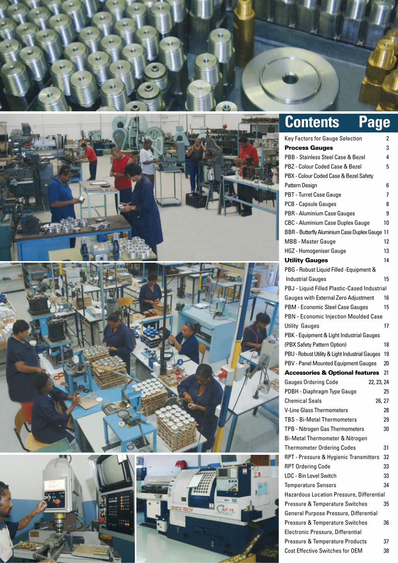
Contents PageKey Factors for Gauge Selection 2
Process Gauges 3
PBB - Stainless Steel Case & Bezel 4
PBZ - Colour Coded Case & Bezel 5
PBX - Colour Coded Case & Bezel Safety
Pattern Design 6
PBT - Turret Case Gauge 7
PCB - Capsule Gauges 8
PBR - Aluminium Case Gauges 9
CBC - Aluminium Case Duplex Gauge 10
BBR - Butterfly Aluminium Case Duplex Gauge 11
MBB - Master Gauge 12
HGZ - Homogeniser Gauge 13
Utility Gauges 14
PBG - Robust Liquid Filled -Equipment &
Industrial Gauges 15
PBJ - Liquid Filled Plastic-Cased Industrial
Gauges with External Zero Adjustment 16
PBM - Economic Steel Case Gauges 15
PBN - Economic Injection Moulded Case
Utility Gauges 17
PBK - Equipment & Light Industrial Gauges
(PBX Safety Pattern Option) 18
PBU - Robust Utility & Light Industrial Gauges 19
PBV - Panel Mounted Equipment Gauges 20
Accessories & Optional features 21
Gauges Ordering Code 22, 23, 24
PDBH - Diaphragm Type Gauge 25
Chemical Seals 26, 27
V-Line Glass Thermometers 28
TBS - Bi-Metal Thermometers 29
TPB - Nitrogen Gas Thermometers 30
Bi-Metal Thermometer & Nitrogen
Thermometer Ordering Codes 31
RPT - Pressure & Hygienic Transmitters 32
RPT Ordering Code 33
LDC - Bin Level Switch 33
Temperature Sensors 34
Hazardous Location Pressure, Differential
Pressure & Temperature Switches 35
General Purpose Pressure, Differential
Pressure & Temperature Switches 36
Electronic Pressure, Differential
Pressure & Temperature Products 37
Cost Effective Switches for OEM 38
Many factors should be evaluated including temperature, vibration, process conditions, pulsation and corrosion, but by carefully considering the 7 key factors outlined below, the chances of correct selection will increase significantly.
Process MediumThe process medium to which the gauge will be exposed is especially important when using a thin walled Bourdon tube because, if the wrong materials are selected, corrosion may occur which could lead to catastrophic failure. Materials which display the essential combination of properties (good spring memory, easy to form, easy to join, reasonably priced) are phosphor bronze, 316 stainless steel and Monel.
Where these materials can’t satisfy the application, a diaphragm seal (gauge isolator) can be added to prevent the process media from contacting the Bourdon tube. This protects the gauge from corrosion attack, and also prevents viscous or dirty media from clogging the small bore Bourdon tube. The only limitation in using a diaphragm seal is that it typically degrades the accuracy of the pressure gauge by an additional 0,5% of the full scale deviation.
Pressure Gauge RangeIt is important to select a pressure range which accommo-dates all anticipated pressure swings, and which prevents excessive needle movement. It is recommended to confine normal operating pressure to 25% - 75% of scale. With fluctuating pressures (e.g. pulsation caused by a pump or compressor), the maximum operating pressure should be lower (50% of the full range).
Gauges in severe service should be liquid filled and throttled to reduce Bourdon tube stresses. To minimise sensing element stress and to extend the life of the gauge use internal throttle screws, pulsation dampeners, pressure snubbers, gauge savers or diaphragm seals.
The EnvironmentTemperature changes affect the elastic modulus of the Bourdon tube to indicate higher pressure than actual as temperature increases, (lower as temperature decreases), except if made with expensive constant modulus materials.
In a liquid filled gauge with an uncompensating case, a temperature increase of as little as 10°C results in internal case pressure build up which causes a downscale pointer shift. An upscale pointer shift can result from a temperature drop of 10°C or more. This potential error most often occurs in pressure ranges of 600kPa or less. In gauges with true case compensation, temperature error from internal case pressure build-up is negligible.
Where ambient conditions are corrosive or contain a large number of particles, specify hermetically sealed and / or liquid filled pressure gauges to prevent foreign elements from entering the case.
Vibration can cause wear to the gears of the rotary movement and can make it difficult to accurately read pressure off an oscillating pointer. Filling a gauge with dampening fluid, such as glycerine, helps prevent these problems.
AccuracyAccuracy is the conformity of a pressure gauge reading to an accepted standard (e.g. deadweight tester). Inaccuracy is the difference (error) between the true value and the indication, expressed as a percent of the span. It includes the combined errors of method, observer, apparatus and environment. Total accuracy error includes hysteresis and repeatability errors. Accuracy is not a percentage of the gauge reading - for mechanical pressure gauges, accuracy is a percentage of the full range, full scale or span of the gauge.
Guidelines are: Test Gauges (0,25% up to 25MPa, above 25MPa up to 100MPa. 0,3%); Critical Processes (0,50%); General Industry Processes (1,0%); Less Critical Commercial Uses (2,0%).
Dial SizeSizes range from 40mm to 250mm diameters, with the 63mm, 100mm and 150mm being the most popular. The dial size is generally determined by the readability require-ments (larger for remote reading and smaller where the gauge is close to the operator). More accurate pressure gauges generally have larger dials as more dial graduations are needed to read the higher degree of accuracy.
ConnectionsFactors to consider include gauge pressures, size and weight, space limitations, leak integrity and past experi-ence. 150mm and 100mm process gauges usually have 1/2” NPT/BSP connections, especially when direct stern mounted and liquid filled. Smaller dial sizes generally have 1/4” or 1/8” connections.
MountingsPressure gauges may be: Direct stem mount bottom connection; Remote wall - surface mount bottom connection; Panel surface mount back connection; Panel hole U clamp (yoke) flush mount back connection; Panel hole front flange flush mount back connection.
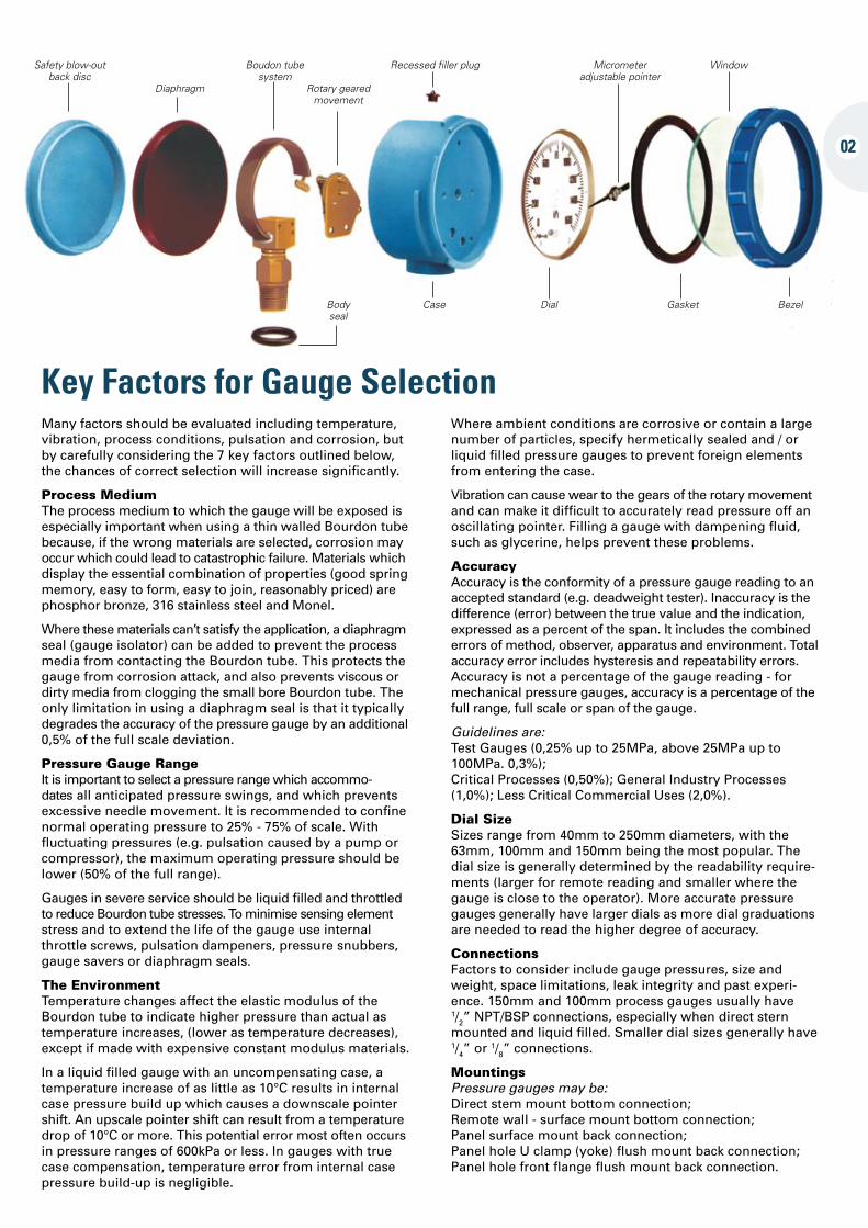
Key Factors for Gauge Selection
Safety blow-out back disc
Diaphragm
Boudon tube system
Rotary geared movement
Recessed filler plug Micrometer adjustable pointer
Window
Body seal
Case Dial Gasket Bezel
02
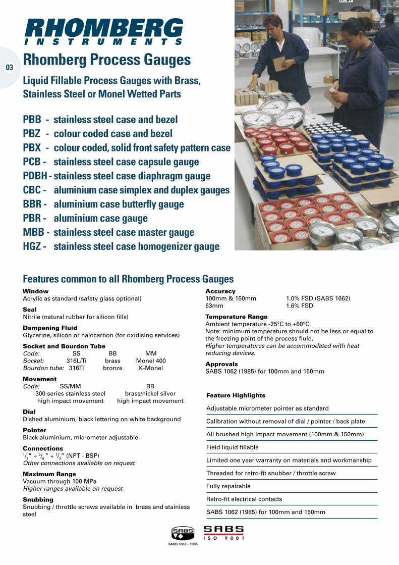
Rhomberg Process GaugesLiquid Fillable Process Gauges with Brass, Stainless Steel or Monel Wetted Parts
PBB - stainless steel case and bezel PBZ - colour coded case and bezel PBX - colour coded, solid front safety pattern case PCB - stainless steel case capsule gauge PDBH- stainless steel case diaphragm gauge CBC - aluminium case simplex and duplex gauges BBR - aluminium case butterfly gauge PBR - aluminium case gauge MBB - stainless steel case master gauge HGZ - stainless steel case homogenizer gauge
Window Acrylic as standard (safety glass optional)
SealNitrile (natural rubber for silicon fills)
Dampening Fluid Glycerine, silicon or halocarbon (for oxidising services)
Socket and Bourdon Tube Code: SS BB MM Socket: 316L/Ti brass Monel 400 Bourdon tube: 316Ti bronze K-Monel
Movement Code: SS/MM BB 300 series stainless steel brass/nickel silver high impact movement high impact movement
DialDished aluminium, black lettering on white background
PointerBlack aluminium, micrometer adjustable
Connections 1/4” + 3/8 ” + 1/2” (NPT - BSP) Other connections available on request
Maximum Range Vacuum through 100 MPa Higher ranges available on request
SnubbingSnubbing / throttle screws available in brass and stainless steel
03
Feature Highlights
Adjustable micrometer pointer as standard
Calibration without removal of dial / pointer / back plate
All brushed high impact movement (100mm & 150mm)
Field liquid fillable
Limited one year warranty on materials and workmanship
Threaded for retro-fit snubber / throttle screw
Fully repairable
Retro-fit electrical contacts
SABS 1062 (1985) for 100mm and 150mm
Accuracy100mm & 150mm 1.0% FSD (SABS 1062) 63mm 1.6% FSD
Temperature Range Ambient temperature -25°C to +60°C Note: minimum temperature should not be less or equal to the freezing point of the process fluid. Higher temperatures can be accommodated with heat reducing devices.
ApprovalsSABS 1062 (1985) for 100mm and 150mm
Features common to all Rhomberg Process Gauges
Conf. A + D A + D B + E B + F F + U
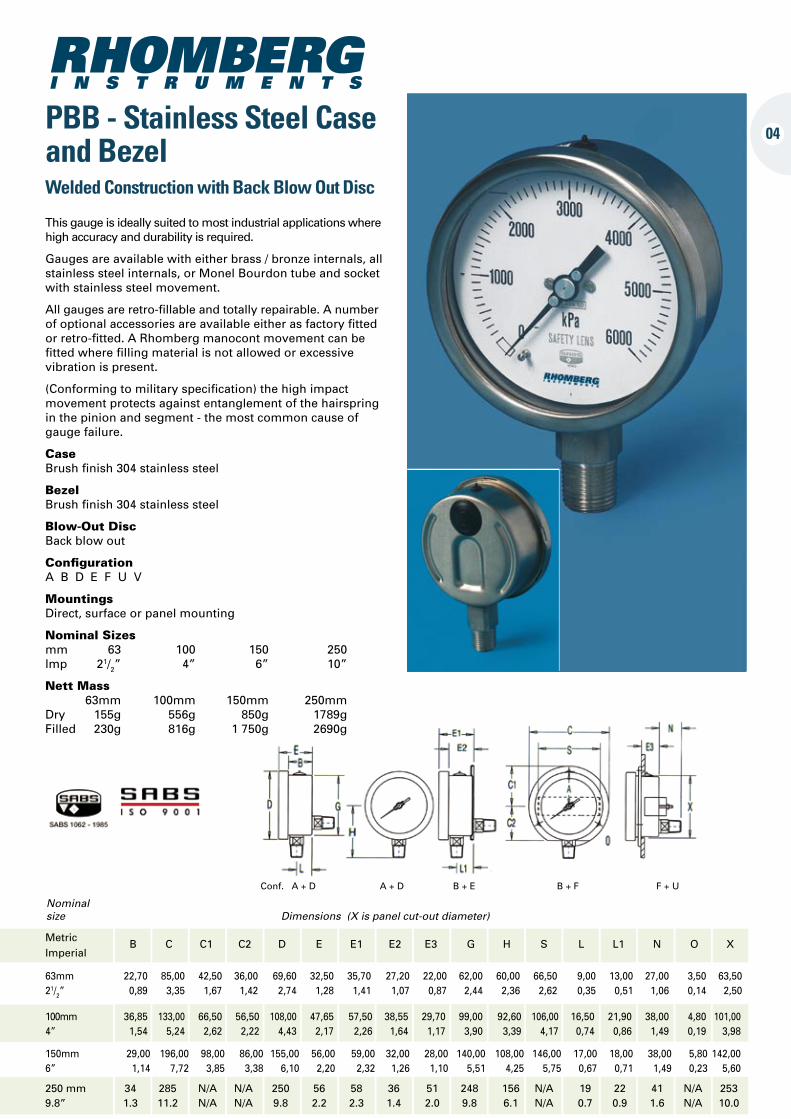
PBB - Stainless Steel Case and Bezel
04
Metric B C C1 C2 D E E1 E2 E3 G H S L L1 N O X Imperial
63mm 22,70 85,00 42,50 36,00 69,60 32,50 35,70 27,20 22,00 62,00 60,00 66,50 9,00 13,00 27,00 3,50 63,50 21/2” 0,89 3,35 1,67 1,42 2,74 1,28 1,41 1,07 0,87 2,44 2,36 2,62 0,35 0,51 1,06 0,14 2,50
100mm 36,85 133,00 66,50 56,50 108,00 47,65 57,50 38,55 29,70 99,00 92,60 106,00 16,50 21,90 38,00 4,80 101,00 4” 1,54 5,24 2,62 2,22 4,43 2,17 2,26 1,64 1,17 3,90 3,39 4,17 0,74 0,86 1,49 0,19 3,98
Nominal size Dimensions (X is panel cut-out diameter)
150mm 29,00 196,00 98,00 86,00 155,00 56,00 59,00 32,00 28,00 140,00 108,00 146,00 17,00 18,00 38,00 5,80 142,00 6” 1,14 7,72 3,85 3,38 6,10 2,20 2,32 1,26 1,10 5,51 4,25 5,75 0,67 0,71 1,49 0,23 5,60
Welded Construction with Back Blow Out Disc
This gauge is ideally suited to most industrial applications where high accuracy and durability is required.
Gauges are available with either brass / bronze internals, all stainless steel internals, or Monel Bourdon tube and socket with stainless steel movement.
All gauges are retro-fillable and totally repairable. A number of optional accessories are available either as factory fitted or retro-fitted. A Rhomberg manocont movement can be fitted where filling material is not allowed or excessive vibration is present.
(Conforming to military specification) the high impact movement protects against entanglement of the hairspring in the pinion and segment - the most common cause of gauge failure.
Case Brush finish 304 stainless steel
Bezel Brush finish 304 stainless steel
Blow-Out Disc Back blow out
Configuration A B D E F U V
MountingsDirect, surface or panel mounting
Nominal Sizes mm 63 100 150 250 lmp 21/2” 4” 6” 10”
Nett Mass 63mm 100mm 150mm 250mm Dry 155g 556g 850g 1789g Filled 230g 816g 1 750g 2690g
250 mm 34 285 N/A N/A 250 56 58 36 51 248 156 N/A 19 22 41 N/A 2539.8” 1.3 11.2 N/A N/A 9.8 2.2 2.3 1.4 2.0 9.8 6.1 N/A 0.7 0.9 1.6 N/A 10.0
Conf. A A B B
D
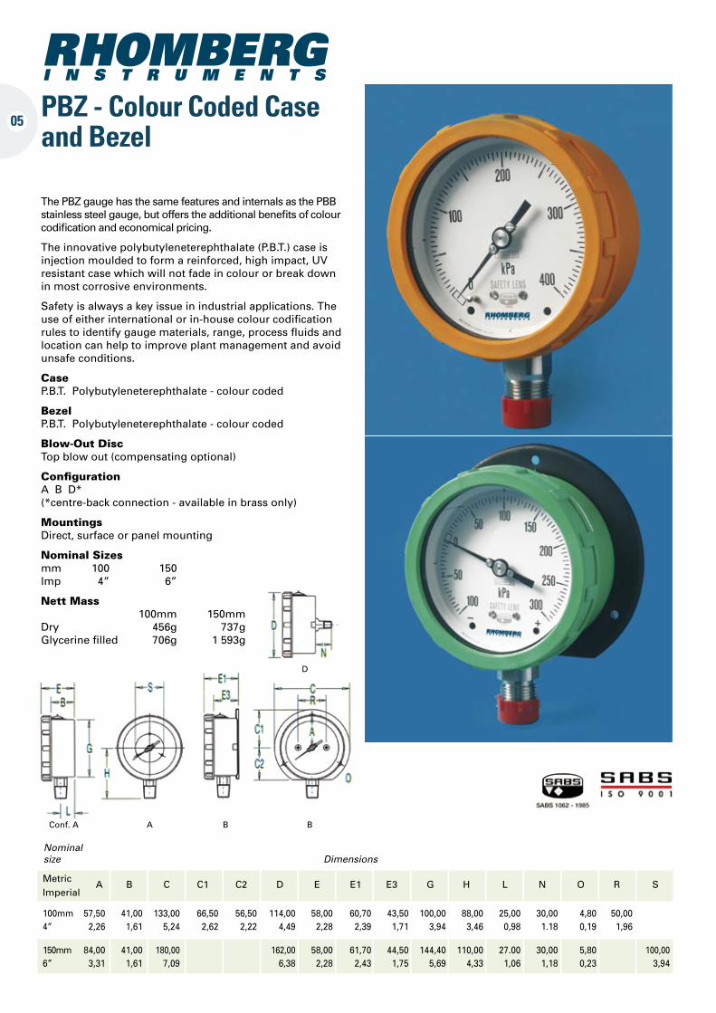
PBZ - Colour Coded Case and Bezel
05
Metric A B C C1 C2 D E E1 E3 G H L N O R S Imperial
100mm 57,50 41,00 133,00 66,50 56,50 114,00 58,00 60,70 43,50 100,00 88,00 25,00 30,00 4,80 50,00 4” 2,26 1,61 5,24 2,62 2,22 4,49 2,28 2,39 1,71 3,94 3,46 0,98 1.18 0,19 1,96
150mm 84,00 41,00 180,00 162,00 58,00 61,70 44,50 144,40 110,00 27.00 30,00 5,80 100,00 6” 3,31 1,61 7,09 6,38 2,28 2,43 1,75 5,69 4,33 1,06 1,18 0,23 3,94
Nominal size Dimensions
The PBZ gauge has the same features and internals as the PBB stainless steel gauge, but offers the additional benefits of colour codification and economical pricing.
The innovative polybutyleneterephthalate (P.B.T.) case is injection moulded to form a reinforced, high impact, UV resistant case which will not fade in colour or break down in most corrosive environments.
Safety is always a key issue in industrial applications. The use of either international or in-house colour codification rules to identify gauge materials, range, process fluids and location can help to improve plant management and avoid unsafe conditions.
Case P.B.T. Polybutyleneterephthalate - colour coded
Bezel P.B.T. Polybutyleneterephthalate - colour coded
Blow-Out Disc Top blow out (compensating optional)
Configuration A B D* (*centre-back connection - available in brass only)
MountingsDirect, surface or panel mounting
Nominal Sizes mm 100 150 lmp 4” 6”
Nett Mass 100mm 150mm Dry 456g 737g Glycerine filled 706g 1 593g
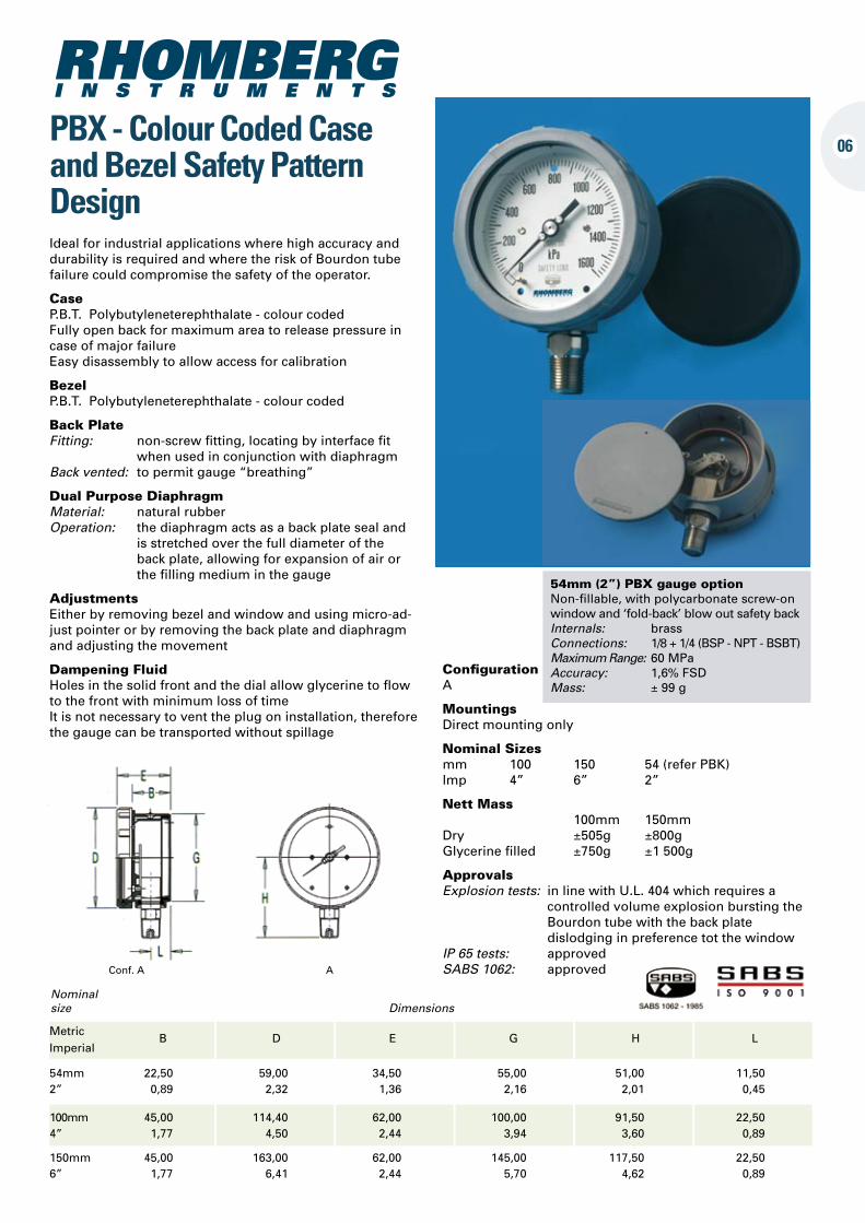
06PBX - Colour Coded Case and Bezel Safety Pattern Design
Metric B D E G H L Imperial
54mm 22,50 59,00 34,50 55,00 51,00 11,50 2” 0,89 2,32 1,36 2,16 2,01 0,45
100mm 45,00 114,40 62,00 100,00 91,50 22,50 4” 1,77 4,50 2,44 3,94 3,60 0,89
150mm 45,00 163,00 62,00 145,00 117,50 22,50 6” 1,77 6,41 2,44 5,70 4,62 0,89
Nominal size Dimensions
54mm (2”) PBX gauge option Non-fillable, with polycarbonate screw-on window and ‘fold-back’ blow out safety back Internals: brass Connections: 1/8 + 1/4 (BSP - NPT - BSBT) Maximum Range: 60 MPa Accuracy: 1,6% FSD Mass: ± 99 g
Conf. A A
Ideal for industrial applications where high accuracy and durability is required and where the risk of Bourdon tube failure could compromise the safety of the operator.
Case P.B.T. Polybutyleneterephthalate - colour coded Fully open back for maximum area to release pressure in case of major failure Easy disassembly to allow access for calibration
Bezel P.B.T. Polybutyleneterephthalate - colour coded
Back Plate Fitting: non-screw fitting, locating by interface fit when used in conjunction with diaphragm Back vented: to permit gauge “breathing”
Dual Purpose Diaphragm Material: natural rubber Operation: the diaphragm acts as a back plate seal and is stretched over the full diameter of the back plate, allowing for expansion of air or the filling medium in the gauge
Adjustments Either by removing bezel and window and using micro-ad-just pointer or by removing the back plate and diaphragm and adjusting the movement
Dampening Fluid Holes in the solid front and the dial allow glycerine to flow to the front with minimum loss of time It is not necessary to vent the plug on installation, therefore the gauge can be transported without spillage
Configuration A
MountingsDirect mounting only
Nominal Sizes mm 100 150 54 (refer PBK) lmp 4” 6” 2”
Nett Mass 100mm 150mm Dry ±505g ±800g Glycerine filled ±750g ±1 500g
Approvals Explosion tests: in line with U.L. 404 which requires a controlled volume explosion bursting the Bourdon tube with the back plate dislodging in preference tot the window IP 65 tests: approved SABS 1062: approved
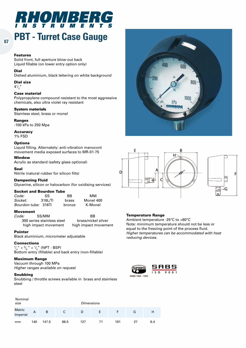
07PBT - Turret Case Gauge
Temperature Range Ambient temperature -25°C to +60°C Note: minimum temperature should not be less or equal to the freezing point of the process fluid. Higher temperatures can be accommodated with heat reducing devices.
mm 140 147.5 66.5 127 71 181 27 6.4
Nominal size Dimensions
Metric A B C D E F G H Imperial
Features Solid front, full aperture blow-out back Liquid fillable (on lower entry option only)
DialDished aluminium, black lettering on white background
Dial size41/2”
Case material Polypropylene compound resistant to the most aggressive chemicals, also ultra violet ray resistant
System materials Stainless steel, brass or monel
Ranges-100 kPa to 250 Mpa
Accuracy 1% FSD
OptionsLiquid filling. Alternately: anti-vibration manocont movement media exposed surfaces to MR-01-75
Window Acrylic as standard (safety glass optional)
SealNitrile (natural rubber for silicon fills)
Dampening Fluid Glycerine, silicon or halocarbon (for oxidising services)
Socket and Bourdon Tube Code: SS BB MM Socket: 316L/Ti brass Monel 400 Bourdon tube: 316Ti bronze K-Monel
Movement Code: SS/MM BB 300 series stainless steel brass/nickel silver high impact movement high impact movement
PointerBlack aluminium, micrometer adjustable
Connections 1/4” + 3/8 ” + 1/2” (NPT - BSP) Bottom entry (fillable) and back entry (non-fillable)
Maximum Range Vacuum through 100 MPa Higher ranges available on request
SnubbingSnubbing / throttle screws available in brass and stainless steel
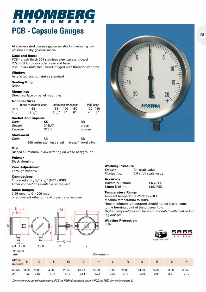
08PCB - Capsule Gauges
68mm 33,50 73,00 45,00 28,50 67,00 56,50 10,00 20,00 51,00 74,00 83,00 68,50 21/2” 1,32 2,87 1,77 1,12 2,64 2,22 0,39 0,79 2,00 2,91 3,27 2,70
Dimensions as per selected casing. PCB (as PBB) dimensions page 4; PCZ (as PBZ) dimensions page 5.
Nominal size Dimensions
Metric B D E E3 G H L N Q R S X Imperial
Conf. A + D A + D V V
All stainless steel pressure gauge suitable for measuring low pressures in dry, gaseous media.
Case and Bezel PCB - brush finish 304 stainless steel case and bezel PCZ - P.B.T. colour coded case and bezel PCK - black mild steel, bezel integral with threaded window
Window Acrylic (polycarbonate) as standard
Sealing Ring Nylon
Mountings Direct, surface or panel mounting
Nominal Sizes black mild steel case stainless steel case PBT casemm 68 63 100 150 100 150 lmp 2 1/2” 2 1/2” 4” 6” 4” 6”
Socket and Capsule Code: SS BB Socket: 316L/Ti brass Capsule: 316Ti bronze
Movement Code: SS BB 300 series stainless steel brass / nickel silver
Dial Dished aluminium, black lettering on white background
Pointer Black aluminium
Zero Adjustment Through window
Connections Threaded entry 1/4” + 1/2” (NPT - BSP) Other connections available on request
Scale Ranges 0-25 mbar to 0-1 000 mbar or equivalent other units of pressure or vacuum
Working Pressure Steady: full scale value Fluctuating: 0,9 x full scale value
Accuracy 100mm & 150mm 1,6% FSD 63mm & 68mm 1,6% FSD
Temperature Range Ambient temperature -25°C to +60°C Medium temperature to 100°C Note: minimum temperature should not be less or equal to the freezing point of the process fluid. Higher temperatures can be accommodated with heat reduc-ing devices
Weather Protection IP 54
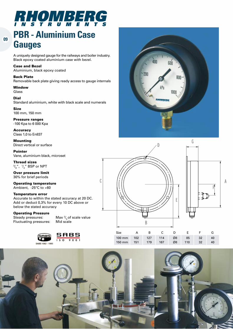
09PBR - Aluminium Case Gauges
Size A B C D E F G
100 mm 102 127 114 Ø8 85 32 40 150 mm 151 179 167 Ø8 110 32 40
A uniquely designed gauge for the railways and boiler industry. Black epoxy coated aluminium case with bezel.
Case and Bezel Aluminium, black epoxy coated
Back Plate Removable back plate giving ready access to gauge internals
Window Glass
Dial Standard aluminium, white with black scale and numerals
Size 100 mm, 150 mm
Pressure ranges -100 Kpa to 6 000 Kpa
Accuracy Class 1,0 to En837
Mounting Direct vertical or surface
Pointer Vane, aluminium black, microset
Thread sizes 3/8”, 1/2” BSP or NPT
Over pressure limit 30% for brief periods
Operating temperature Ambient, -25°C to +60
Temperature error Accurate to within the stated accuracy at 20 DC. Add or deduct 0,3% for every 10 DC above or below the stated accuracy
Operating Pressure Steady pressures: Max 2/3 of scale value Fluctuating pressures: Mid scale
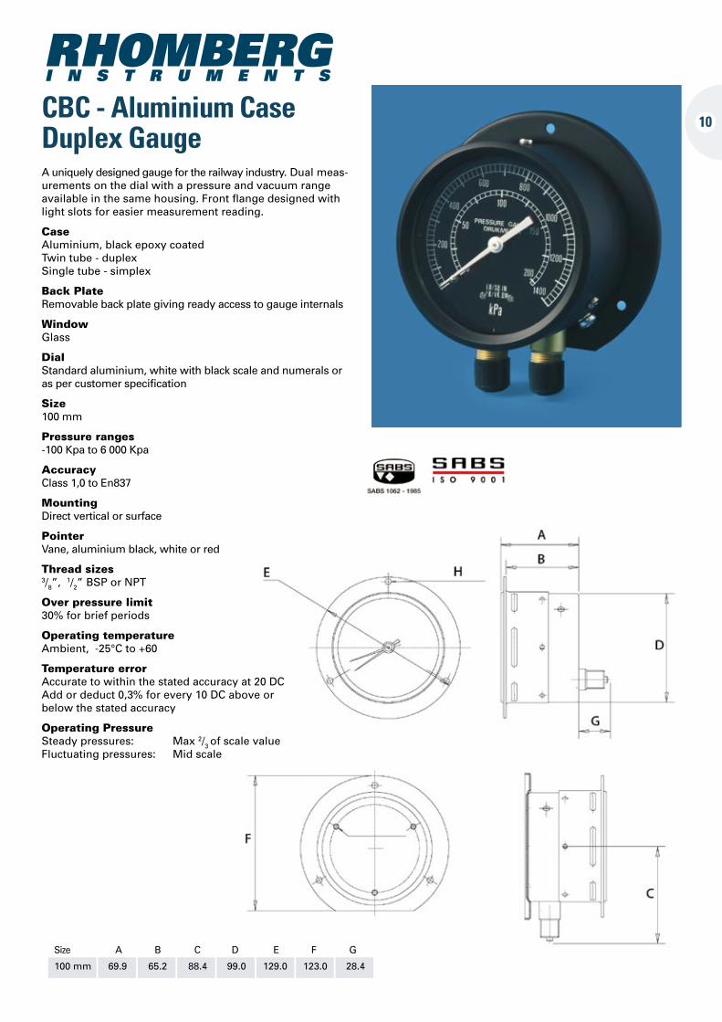
CBC - Aluminium Case Duplex Gauge
10
Size A B C D E F G
100 mm 69.9 65.2 88.4 99.0 129.0 123.0 28.4
A uniquely designed gauge for the railway industry. Dual meas-urements on the dial with a pressure and vacuum range available in the same housing. Front flange designed with light slots for easier measurement reading.
Case Aluminium, black epoxy coated Twin tube - duplex Single tube - simplex
Back Plate Removable back plate giving ready access to gauge internals
Window Glass
Dial Standard aluminium, white with black scale and numerals or as per customer specification
Size 100 mm
Pressure ranges -100 Kpa to 6 000 Kpa
Accuracy Class 1,0 to En837
Mounting Direct vertical or surface
Pointer Vane, aluminium black, white or red
Thread sizes 3/8”, 1/2” BSP or NPT
Over pressure limit 30% for brief periods
Operating temperature Ambient, -25°C to +60
Temperature error Accurate to within the stated accuracy at 20 DC Add or deduct 0,3% for every 10 DC above or below the stated accuracy
Operating Pressure Steady pressures: Max 2/3 of scale value Fluctuating pressures: Mid scale
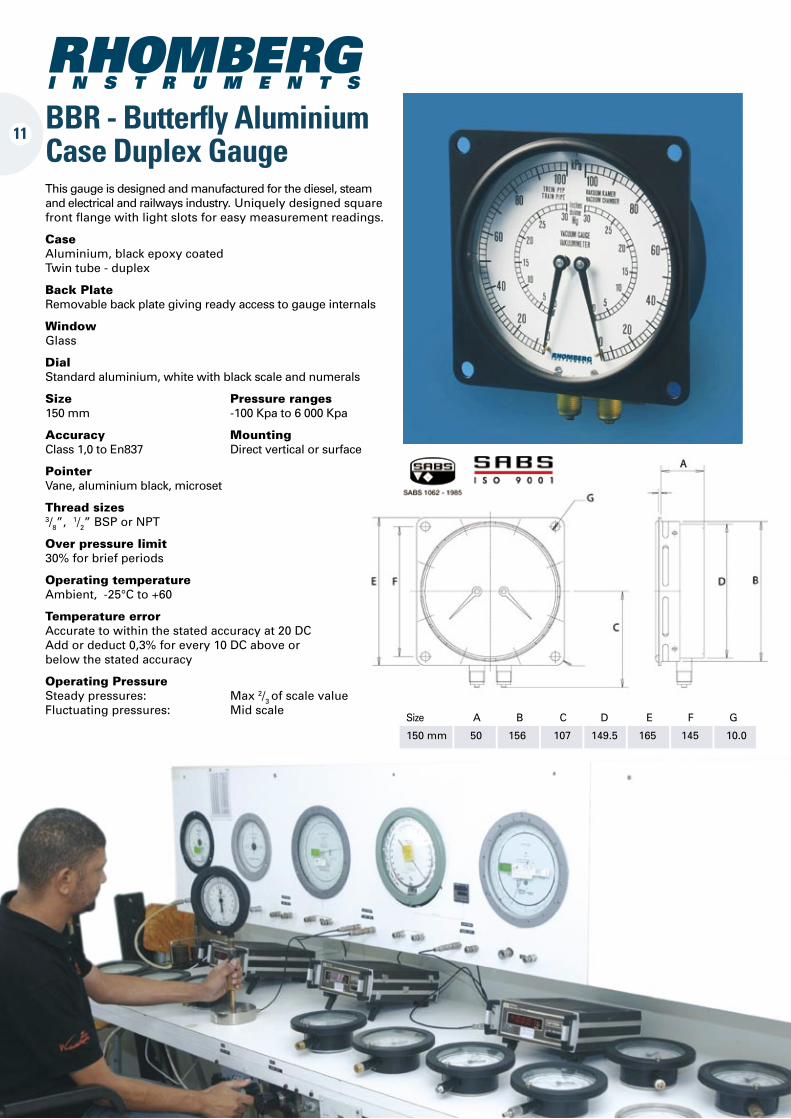
11BBR - Butterfly Aluminium Case Duplex GaugeThis gauge is designed and manufactured for the diesel, steam and electrical and railways industry. Uniquely designed square front flange with light slots for easy measurement readings.
Case Aluminium, black epoxy coated Twin tube - duplex
Back Plate Removable back plate giving ready access to gauge internals
Window Glass
Dial Standard aluminium, white with black scale and numerals
Size Pressure ranges 150 mm -100 Kpa to 6 000 Kpa
Accuracy Mounting Class 1,0 to En837 Direct vertical or surface
Pointer Vane, aluminium black, microset
Thread sizes 3/8”, 1/2” BSP or NPT
Over pressure limit 30% for brief periods
Operating temperature Ambient, -25°C to +60
Temperature error Accurate to within the stated accuracy at 20 DC Add or deduct 0,3% for every 10 DC above or below the stated accuracy
Operating Pressure Steady pressures: Max 2/3 of scale value Fluctuating pressures: Mid scale
Size A B C D E F G
150 mm 50 156 107 149.5 165 145 10.0
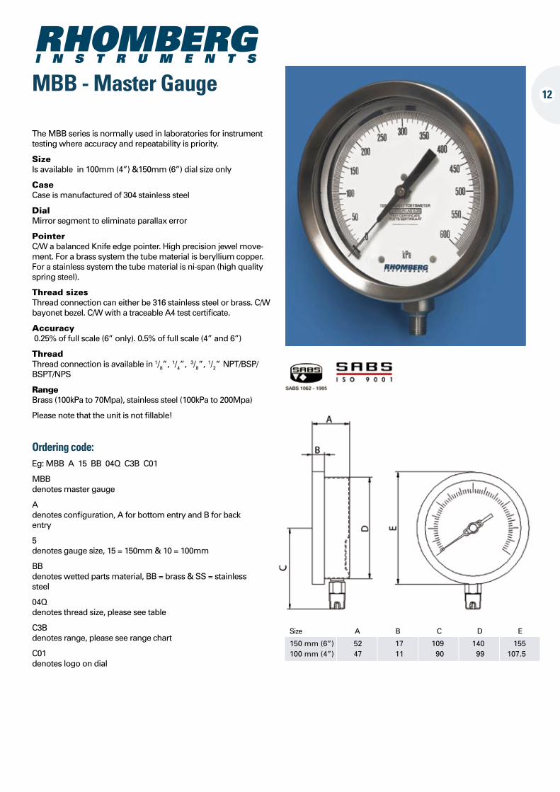
Ordering code:Eg: MBB A 15 BB 04Q C3B C01
MBB denotes master gauge
A denotes configuration, A for bottom entry and B for back entry
5 denotes gauge size, 15 = 150mm & 10 = 100mm
BB denotes wetted parts material, BB = brass & SS = stainless steel
04Q denotes thread size, please see table
C3B denotes range, please see range chart
C01 denotes logo on dial
The MBB series is normally used in laboratories for instrument testing where accuracy and repeatability is priority.
SizeIs available in 100mm (4”) &150mm (6”) dial size only
Case Case is manufactured of 304 stainless steel
Dial Mirror segment to eliminate parallax error
Pointer C/W a balanced Knife edge pointer. High precision jewel move-ment. For a brass system the tube material is beryllium copper. For a stainless system the tube material is ni-span (high quality spring steel).
Thread sizes Thread connection can either be 316 stainless steel or brass. C/W bayonet bezel. C/W with a traceable A4 test certificate.
Accuracy 0.25% of full scale (6” only). 0.5% of full scale (4” and 6”)
Thread Thread connection is available in 1/8”, 1/4”,
3/8”, 1/2” NPT/BSP/BSPT/NPS
Range Brass (100kPa to 70Mpa), stainless steel (100kPa to 200Mpa)
Please note that the unit is not fillable!
12MBB - Master Gauge
Size A B C D E
150 mm (6”) 52 17 109 140 155 100 mm (4”) 47 11 90 99 107.5
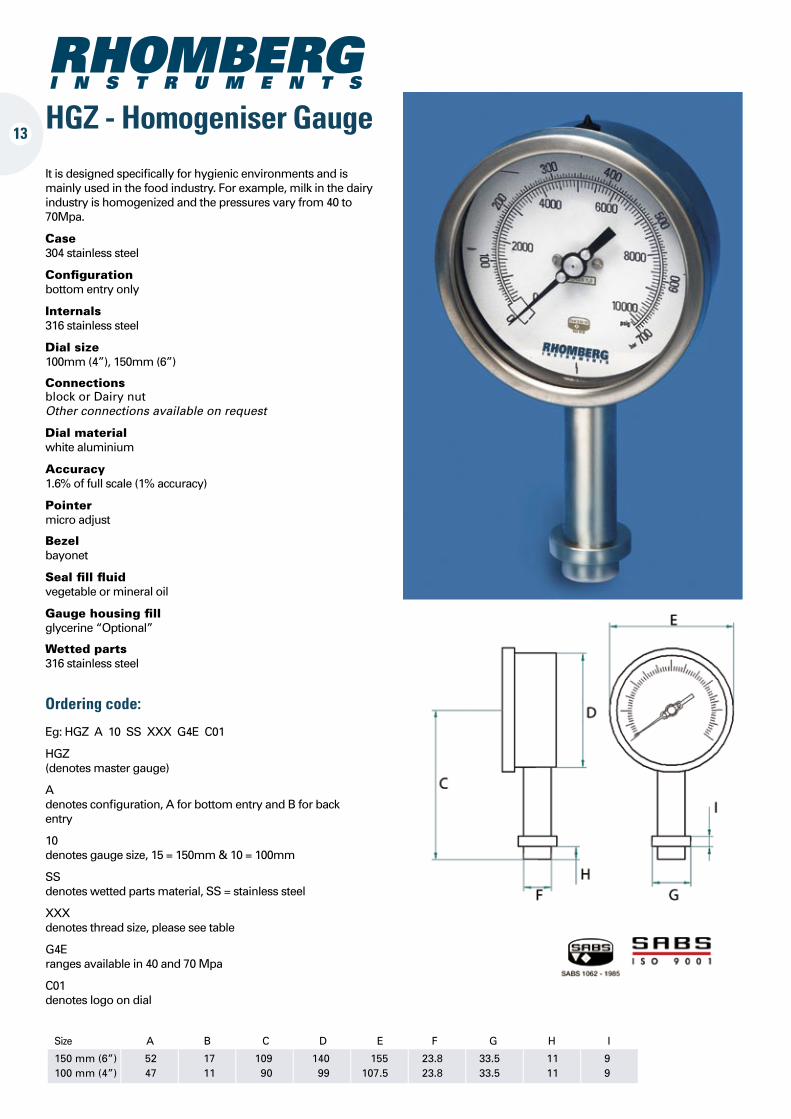
13HGZ - Homogeniser Gauge
It is designed specifically for hygienic environments and is mainly used in the food industry. For example, milk in the dairy industry is homogenized and the pressures vary from 40 to 70Mpa.
Case 304 stainless steel
Configuration bottom entry only
Internals 316 stainless steel
Dial size 100mm (4”), 150mm (6”)
Connections block or Dairy nut Other connections available on request
Dial material white aluminium
Accuracy 1.6% of full scale (1% accuracy)
Pointer micro adjust
Bezel bayonet
Seal fill fluid vegetable or mineral oil
Gauge housing fill glycerine “Optional”
Wetted parts 316 stainless steel
Ordering code:
Eg: HGZ A 10 SS XXX G4E C01
HGZ (denotes master gauge)
A denotes configuration, A for bottom entry and B for back entry
10 denotes gauge size, 15 = 150mm & 10 = 100mm
SS denotes wetted parts material, SS = stainless steel
XXX denotes thread size, please see table
G4E ranges available in 40 and 70 Mpa
C01 denotes logo on dial
Size A B C D E F G H I
150 mm (6”) 52 17 109 140 155 23.8 33.5 11 9 100 mm (4”) 47 11 90 99 107.5 23.8 33.5 11 9
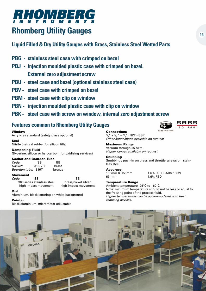
Rhomberg Utility Gauges
Liquid Filled & Dry Utility Gauges with Brass, Stainless Steel Wetted Parts
PBG - stainless steel case with crimped on bezel PBJ - injection moulded plastic case with crimped on bezel. External zero adjustment screw PBU - steel case and bezel (optional stainless steel case) PBV - steel case with crimped on bezel PBM - steel case with clip on window PBN - injection moulded plastic case with clip on window PBK - steel case with screw on window, internal zero adjustment screw
Window Acrylic as standard (safety glass optional)
SealNitrile (natural rubber for silicon fills)
Dampening Fluid Glycerine, silicon or halocarbon (for oxidising services)
Socket and Bourdon Tube Code: SS BB Socket: 316L/Ti brass Bourdon tube: 316Ti bronze
Movement Code: SS BB 300 series stainless steel brass/nickel silver high impact movement high impact movement
DialAluminium, black lettering on white background
PointerBlack aluminium, micrometer adjustable
Connections 1/4” + 3/8 ” + 1/2” (NPT - BSP) Other connections available on request
Maximum Range Vacuum through 25 MPa Higher ranges available on request
SnubbingSnubbing / push-in on brass and throttle screws on stain-less steel
Accuracy100mm & 150mm 1.6% FSD (SABS 1062) 63mm 1.6% FSD
Temperature Range Ambient temperature -25°C to +60°C Note: minimum temperature should not be less or equal to the freezing point of the process fluid. Higher temperatures can be accommodated with heat reducing devices.
Features common to Rhomberg Utility Gauges
14
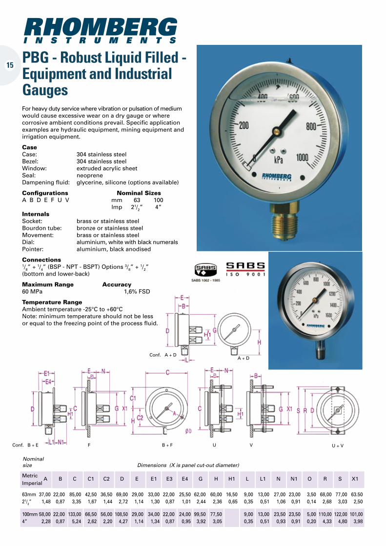
PBG - Robust Liquid Filled - Equipment and Industrial Gauges
Metric A B C C1 C2 D E E1 E3 E4 G H H1 L L1 N N1 O R S X1 Imperial
63mm 37,00 22,00 85,00 42,50 36,50 69,00 29,00 33,00 22,00 25,50 62,00 60,00 16,50 9,00 13,00 27,00 23,00 3,50 68,00 77,00 63.50 21/2” 1,48 0,87 3,35 1,67 1,44 2,72 1,14 1,30 0,87 1,01 2,44 2,36 0,65 0,35 0,51 1,06 0,91 0,14 2,68 3,03 2,50
100mm 58,00 22,00 133,00 66,50 56,00 108,50 29,00 34,00 22,00 24,00 99,50 77,50 9,00 13,00 23,50 23,50 5,00 110,00 122,00 101,00 4” 2,28 0,87 5,24 2,62 2,20 4,27 1,14 1,34 0,87 0,95 3,92 3,05 0,35 0,51 0,93 0,91 0,20 4,33 4,80 3,98
Nominal size Dimensions (X is panel cut-out diameter)
Conf. A + DA + D
V U + VUB + FFConf. B + E
For heavy duty service where vibration or pulsation of medium would cause excessive wear on a dry gauge or where corrosive ambient conditions prevail. Specific application examples are hydraulic equipment, mining equipment and irrigation equipment.
Case Case: 304 stainless steel Bezel: 304 stainless steel Window: extruded acrylic sheet Seal: neoprene Dampening fluid: glycerine, silicone (options available)
Configurations Nominal Sizes A B D E F U V mm 63 100 lmp 21/2” 4”Internals Socket: brass or stainless steel Bourdon tube: bronze or stainless steel Movement: brass or stainless steel Dial: aluminium, white with black numerals Pointer: aluminium, black anodised
Connections 1/8” + 1/4” (BSP - NPT - BSPT) Options 3/8” + 1/2” (bottom and lower-back)
Maximum Range Accuracy 60 MPa 1,6% FSD
Temperature Range Ambient temperature -25°C to +60°C Note: minimum temperature should not be less or equal to the freezing point of the process fluid.
15
16
Metric B D E G H L Imperial
63mm 25,00 68,50 33,00 63,50 52,00 13,00 21/2” 1,00 2,70 1,30 2,50 2,05 0,51
80mm 26,50 85,00 34,00 79,50 60,50 14,40 31/8” 1,04 3,35 1,34 3,13 2,38 0,57
Nominal size Dimensions
Conf. A
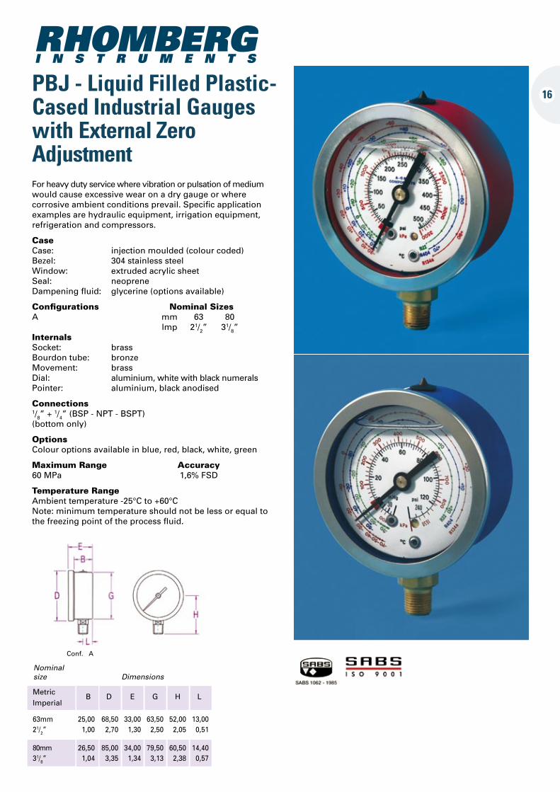
PBJ - Liquid Filled Plastic-Cased Industrial Gauges with External Zero AdjustmentFor heavy duty service where vibration or pulsation of medium would cause excessive wear on a dry gauge or where corrosive ambient conditions prevail. Specific application examples are hydraulic equipment, irrigation equipment, refrigeration and compressors.
Case Case: injection moulded (colour coded) Bezel: 304 stainless steel Window: extruded acrylic sheet Seal: neoprene Dampening fluid: glycerine (options available)
Configurations Nominal Sizes A mm 63 80 lmp 21/2” 31/8”Internals Socket: brass Bourdon tube: bronze Movement: brass Dial: aluminium, white with black numerals Pointer: aluminium, black anodised
Connections 1/8” + 1/4” (BSP - NPT - BSPT) (bottom only)
Options Colour options available in blue, red, black, white, green
Maximum Range Accuracy 60 MPa 1,6% FSD
Temperature Range Ambient temperature -25°C to +60°C Note: minimum temperature should not be less or equal to the freezing point of the process fluid.
Conf. A D V
PBN - Economic Injection Moulded Case Utility Gauges
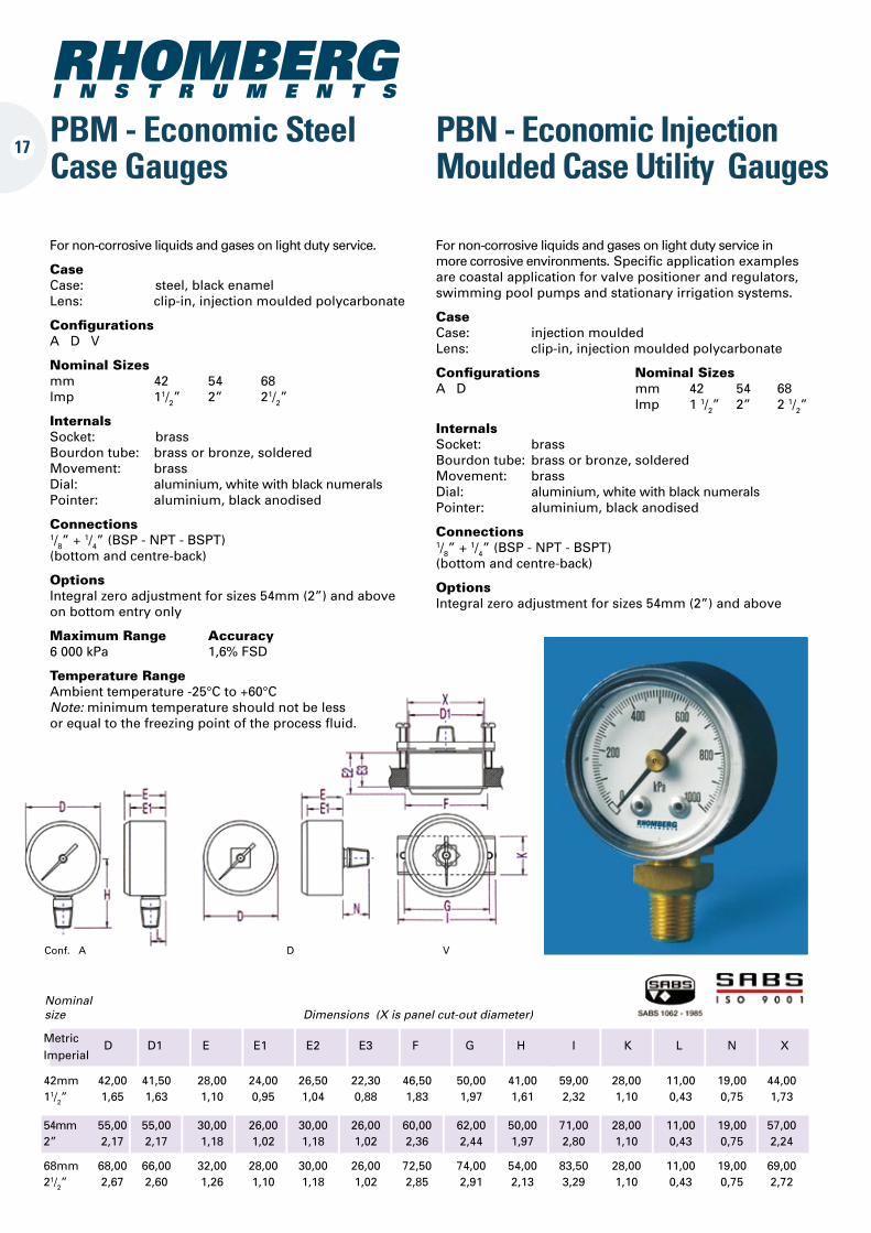
PBM - Economic Steel Case Gauges
42mm 42,00 41,50 28,00 24,00 26,50 22,30 46,50 50,00 41,00 59,00 28,00 11,00 19,00 44,00 11/2” 1,65 1,63 1,10 0,95 1,04 0,88 1,83 1,97 1,61 2,32 1,10 0,43 0,75 1,73
54mm 55,00 55,00 30,00 26,00 30,00 26,00 60,00 62,00 50,00 71,00 28,00 11,00 19,00 57,00 2” 2,17 2,17 1,18 1,02 1,18 1,02 2,36 2,44 1,97 2,80 1,10 0,43 0,75 2,24
68mm 68,00 66,00 32,00 28,00 30,00 26,00 72,50 74,00 54,00 83,50 28,00 11,00 19,00 69,00 21/2” 2,67 2,60 1,26 1,10 1,18 1,02 2,85 2,91 2,13 3,29 1,10 0,43 0,75 2,72
Nominal size Dimensions (X is panel cut-out diameter)
Metric D D1 E E1 E2 E3 F G H I K L N X Imperial
For non-corrosive liquids and gases on light duty service.
Case Case: steel, black enamel Lens: clip-in, injection moulded polycarbonate
Configurations A D V
Nominal Sizes mm 42 54 68 lmp 11/2” 2” 21/2”
Internals Socket: brass Bourdon tube: brass or bronze, soldered Movement: brass Dial: aluminium, white with black numerals Pointer: aluminium, black anodised
Connections 1/8” + 1/4” (BSP - NPT - BSPT) (bottom and centre-back)
Options Integral zero adjustment for sizes 54mm (2”) and above on bottom entry only
Maximum Range Accuracy 6 000 kPa 1,6% FSD
Temperature Range Ambient temperature -25°C to +60°C Note: minimum temperature should not be less or equal to the freezing point of the process fluid.
For non-corrosive liquids and gases on light duty service in more corrosive environments. Specific application examples are coastal application for valve positioner and regulators, swimming pool pumps and stationary irrigation systems.
Case Case: injection moulded Lens: clip-in, injection moulded polycarbonate
Configurations Nominal Sizes A D mm 42 54 68 lmp 1 1/2” 2” 2 1/2”
Internals Socket: brass Bourdon tube: brass or bronze, soldered Movement: brass Dial: aluminium, white with black numerals Pointer: aluminium, black anodised
Connections 1/8” + 1/4” (BSP - NPT - BSPT) (bottom and centre-back)
Options Integral zero adjustment for sizes 54mm (2”) and above
17
18
Conf. A + D A + D V V
Conf. A A
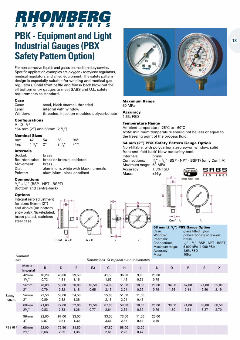
PBK - Equipment and Light Industrial Gauges (PBX Safety Pattern Option)
Maximum Range 60 MPa
Accuracy 1,6% FSD
Temperature Range Ambient temperature -25°C to +60°C Note: minimum temperature should not be less or equal to the freezing point of the process fluid.
54 mm (2”) PBX Safety Pattern Gauge Option Non-fillable, with polycarbonatescrew-on window, solid front and ‘fold-back’ blow-out safety back Internals: brass Connections: 1/8” + 1/4” (BSP - NPT - BSPT) (only Conf. A) Maximum range: 60 MPa Accuracy: 1,6% FSD Mass: ±99g
68 mm (2 1/2”) PBS Gauge Option Case: glass filled nylon Window: polycarbonate screw-on Internals: brass Connections: 1/8” + 1/4” (BSP - NPT - BSPT) Maximum range: 6 000 kPa (1 000 PSI) Accuracy: 1,6% FSD Mass: 105g Nominal
size Dimensions (X is panel cut-out diameter)
Metric B D E E3 G H L N Q R S X Imperial
Safety Pattern
42mm 18,20 46,00 29,50 41,50 36,00 9,00 20,00 11/2” 0,72 1,81 1,16 1,63 1,42 0,35 0,79
54mm 20,00 59,00 30,00 16,50 54,00 51,00 10,00 20,00 34,50 62,00 71,00 55,00 2” 0,79 2,32 1,18 0,65 2,13 2,01 0,39 0,79 1,36 2,44 2,80 2,19
54mm 22,50 59,00 34,50 55,00 51,00 11,50 2” 0,89 2,32 1,36 2,16 2,01 0,45
68mm 21,00 72,00 32,00 19,50 67,00 59,00 10,00 20,00 38,00 74,00 83,00 68,50 21/2” 0,83 2,83 1,26 0,77 2,64 2,32 0,39 0,79 1,50 2,91 3,27 2,70
96mm 22,00 97,00 33,00 93,00 73,00 11,00 20,00 4” 0,87 3,81 1,30 3,66 2,87 0,43 0,79
68mm 22,00 72,50 34,50 67,50 58,00 12,00 21/2” 8,66 2,85 1,36 2,66 2,28 0,47
PBS 68*
For non-corrosive liquids and gases on medium duty service. Specific application examples are oxygen / acetylene regulators, medical regulators and allied equipment. The safety pattern design is especially suitable for welding and medical gas regulators. Solid front baffle and flimsy back blow-out for all bottom entry gauges to meet SABS and U.L. safety requirements as standard.
Case Case: steel, black enamel, threaded Lens: integral with window Window: threaded, injection moulded polycarbonate
Configurations A D V* *54 mm (2”) and 68mm (2 1/2”)
Nominal Sizes mm 42 54 68 96* lmp 1 1/2” 2” 2 1/2” 4”*
Internals Socket: brass Bourdon tube: brass or bronze, soldered Movement: brass Dial: aluminium, white with black numerals Pointer: aluminium, black anodised
Connections 1/8” + 1/4” (BSP - NPT - BSPT) (bottom and centre-back)
Options Integral zero adjustment for sizes 54mm (2”) and above (on bottom entry only). Nickel-plated, brass-plated, stainless steel case
Conf. A + D
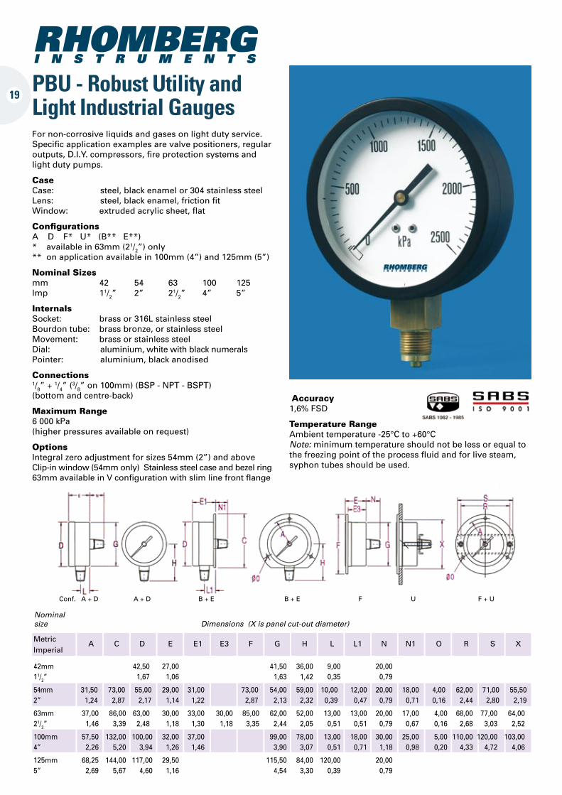
PBU - Robust Utility and Light Industrial Gauges
A + D B + E B + E F U F + U
Nominal size Dimensions (X is panel cut-out diameter)
Metric A C D E E1 E3 F G H L L1 N N1 O R S X Imperial
42mm 42,50 27,00 41,50 36,00 9,00 20,00 11/2” 1,67 1,06 1,63 1,42 0,35 0,79
54mm 31,50 73,00 55,00 29,00 31,00 73,00 54,00 59,00 10,00 12,00 20,00 18,00 4,00 62,00 71,00 55,50 2” 1,24 2,87 2,17 1,14 1,22 2,87 2,13 2,32 0,39 0,47 0,79 0,71 0,16 2,44 2,80 2,19
63mm 37,00 86,00 63,00 30,00 33,00 30,00 85,00 62,00 52,00 13,00 13,00 20,00 17,00 4,00 68,00 77,00 64,00 21/2” 1,46 3,39 2,48 1,18 1,30 1,18 3,35 2,44 2,05 0,51 0,51 0,79 0,67 0,16 2,68 3,03 2,52
100mm 57,50 132,00 100,00 32,00 37,00 99,00 78,00 13,00 18,00 30,00 25,00 5,00 110,00 120,00 103,00 4” 2,26 5,20 3,94 1,26 1,46 3,90 3,07 0,51 0,71 1,18 0,98 0,20 4,33 4,72 4,06
125mm 68,25 144,00 117,00 29,50 115,50 84,00 120,00 20,00 5” 2,69 5,67 4,60 1,16 4,54 3,30 0,39 0,79
For non-corrosive liquids and gases on light duty service. Specific application examples are valve positioners, regular outputs, D.I.Y. compressors, fire protection systems and light duty pumps.
Case Case: steel, black enamel or 304 stainless steel Lens: steel, black enamel, friction fit Window: extruded acrylic sheet, flat
Configurations A D F* U* (B** E**) * available in 63mm (21/2”) only ** on application available in 100mm (4”) and 125mm (5”)
Nominal Sizes mm 42 54 63 100 125 lmp 11/2” 2” 21/2” 4” 5”
Internals Socket: brass or 316L stainless steel Bourdon tube: brass bronze, or stainless steel Movement: brass or stainless steel Dial: aluminium, white with black numerals Pointer: aluminium, black anodised
Connections 1/8” + 1/4” (3/8” on 100mm) (BSP - NPT - BSPT) (bottom and centre-back)
Maximum Range 6 000 kPa (higher pressures available on request)
Options Integral zero adjustment for sizes 54mm (2”) and above Clip-in window (54mm only) Stainless steel case and bezel ring 63mm available in V configuration with slim line front flange
Accuracy 1,6% FSD
Temperature Range Ambient temperature -25°C to +60°C Note: minimum temperature should not be less or equal to the freezing point of the process fluid and for live steam, syphon tubes should be used.
19
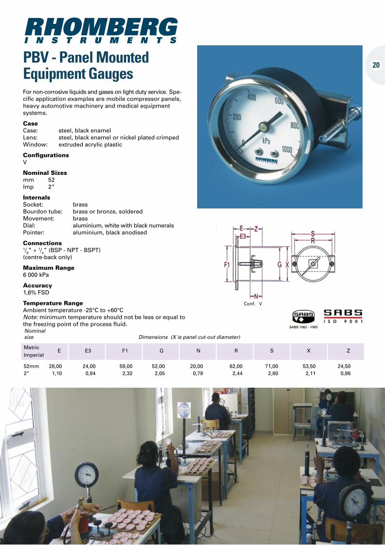
20PBV - Panel Mounted Equipment Gauges
Conf. V
52mm 28,00 24,00 59,00 52,00 20,00 62,00 71,00 53,50 24,50 2” 1,10 0,94 2,32 2,05 0,79 2,44 2,80 2,11 0,96
Nominal size Dimensions (X is panel cut-out diameter)
Metric E E3 F1 G N R S X Z Imperial
For non-corrosive liquids and gases on light duty service. Spe-cific application examples are mobile compressor panels, heavy automotive machinery and medical equipment systems.
Case Case: steel, black enamel Lens: steel, black enamel or nickel plated crimped Window: extruded acrylic plastic
Configurations V
Nominal Sizes mm 52 lmp 2”
Internals Socket: brass Bourdon tube: brass or bronze, soldered Movement: brass Dial: aluminium, white with black numerals Pointer: aluminium, black anodised
Connections 1/8” + 1/4” (BSP - NPT - BSPT) (centre-back only)
Maximum Range 6 000 kPa
Accuracy 1,6% FSD
Temperature Range Ambient temperature -25°C to +60°C Note: minimum temperature should not be less or equal to the freezing point of the process fluid.
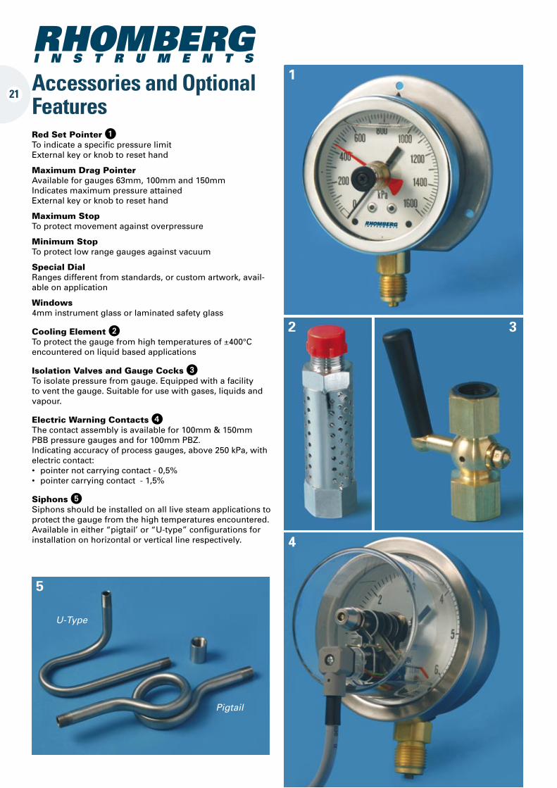
Red Set Pointer 1To indicate a specific pressure limit External key or knob to reset hand
Maximum Drag PointerAvailable for gauges 63mm, 100mm and 150mm Indicates maximum pressure attained External key or knob to reset hand
Maximum StopTo protect movement against overpressure
Minimum StopTo protect low range gauges against vacuum
Special DialRanges different from standards, or custom artwork, avail-able on application
Windows4mm instrument glass or laminated safety glass
Cooling Element 2To protect the gauge from high temperatures of ±400°C encountered on liquid based applications
Isolation Valves and Gauge Cocks 3To isolate pressure from gauge. Equipped with a facility to vent the gauge. Suitable for use with gases, liquids and vapour.
Electric Warning Contacts 4 The contact assembly is available for 100mm & 150mm PBB pressure gauges and for 100mm PBZ. Indicating accuracy of process gauges, above 250 kPa, with electric contact: • pointernotcarryingcontact-0,5% • pointercarryingcontact-1,5%
Siphons 5 Siphons should be installed on all live steam applications to protect the gauge from the high temperatures encountered. Available in either “pigtail’ or “U-type” configurations for installation on horizontal or vertical line respectively.
U-Type
Pigtail
Accessories and Optional Features
1
2 3
4
5
21
22
Case design
Configuration
Nominal size
System material
Thread type
Thread size
Case material & Colour
Range
Customer reference
Option 1
Option 2
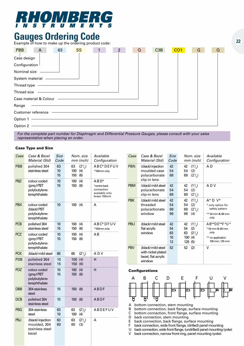
Gauges Ordering CodeExample of how to make up the ordering product code:
For the complete part number for Diaphragm and Differential Pressure Gauges, please consult with your sales representative when placing an order.
PBB A 63 SS 1 2 Q C3B CO1 G Q
Case Type and Size
Case Case & Bezel Size Nom. size Available Material (Std) Code mm (inch) Configuration
PBB polished 304 63 63 (21/2) A B C* D E F U V stainless steel 10 100 (4) *100mm only 15 150 (6)
PBZ colour coded 10 100 (4) A B D* (grey) PBT 15 150 (6) *centre-back polybutylene- connection terephthalate available only
brass 100mm
PBX colour coded 10 100 (4) A (black) PBT polybutylene- terephthalate
PCB polished 304 10 100 (4) A B C* D F U V stainless steel 15 150 (6) *100mm only
PCZ colour coded 10 100 (4) A B (grey) PBT 15 150 (6) polybutylene- terephthalate
PCK (black) mild steel 68 68 (21/2) A D V
PDB polished 304 10 100 (4) H stainless steel 15 150 (6)
PDZ colour coded 10 100 (4) H (grey) PBT 15 150 (6) polybutylene- terephthalate
DBB 304 stainless 15 150 (6) A B D F steel
DCB polished 304 15 150 (6) A B D F stainless steel
PBG 304 stainless 63 63 (21/2) A B D E F U V steel 10 100 (4)
PBJ (black) injection 63 63 (21/2) A moulded, 304 80 80 (3) stainless steel bezel
Case Case & Bezel Size Nom. size Available Material (Std) Code mm (inch) Configuration
PBN (black) injection 42 42 (11/2) A D moulded case 54 54 (2) polycarbonate 68 68 (21/2) clip-in lens
PBM (black) mild steel 42 42 (11/2) A D V polycarbonate 54 54 (2) clip-in lens 68 68 (21/2)
PBK (black) mild steel 42 42 (11/2) A* D V* threaded 54 54 (2) * only option for polycarbonate 68 68 (21/2) safety pattern window 96 96 (4) ** 54 mm & 68 mm only
PBU (black) mild steel 42 42 (11/2) A B**D E**F *U * flat acrylic 54 54 (2) * 54 mm & 68 mm window 63 63 (21/2) only
10 100 (4) ** on application
12 125 (5) 100 mm, 125 mm
PBV (black) mild steel 52 52 (2) V with nickel plated bezel, flat acrylic window
Configurations
A B C D E F U V
A bottom connection, stem mounting B bottom connection, back flange, surface mounting C bottom connection, front flange, surface mounting D back connection, stem mounting E back connection, back flange, surface mounting F back connection, wide front flange, (drilled) panel mounting U back connection, wide front flange, (undrilled) panel mounting (yoke) V back connection, narrow front-ring, panel mounting (yoke)
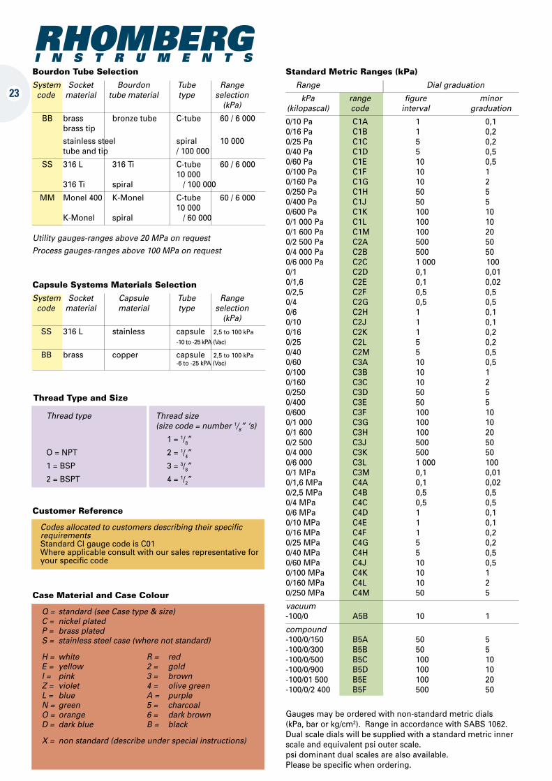
Bourdon Tube Selection
System Socket Bourdon Tube Range code material tube material type selection (kPa)
BB brass bronze tube C-tube 60 / 6 000 brass tip
stainless steel spiral 10 000 tube and tip / 100 000
SS 316 L 316 Ti C-tube 60 / 6 000 10 000 316 Ti spiral / 100 000
MM Monel 400 K-Monel C-tube 60 / 6 000 10 000 K-Monel spiral / 60 000
Utility gauges-ranges above 20 MPa on requestProcess gauges-ranges above 100 MPa on request
Capsule Systems Materials Selection
System Socket Capsule Tube Range code material material type selection (kPa)
SS 316 L stainless capsule 2,5 to 100 kPa
-10 to -25 kPA (Vac)
BB brass copper capsule 2,5 to 100 kPa -6 to -25 kPA (Vac)
Thread Type and Size
Thread type Thread size (size code = number 1/8” ‘s)
1 = 1/8”
O = NPT 2 = 1/4”
1 = BSP 3 = 3/8”
2 = BSPT 4 = 1/2”
Customer Reference
Codes allocated to customers describing their specific requirementsStandard CI gauge code is C01 Where applicable consult with our sales representative for your specific code
Case Material and Case Colour
Q = standard (see Case type & size) C = nickel plated P = brass plated S = stainless steel case (where not standard)
H = white R = red E = yellow 2 = gold I = pink 3 = brown Z = violet 4 = olive green L = blue A = purple N = green 5 = charcoal O = orange 6 = dark brown D = dark blue B = black
X = non standard (describe under special instructions)
Standard Metric Ranges (kPa)
Range l Dial graduation
kPa range figure minor (kilopascal) code interval graduation
0/10 Pa C1A 1 0,1 0/16 Pa C1B 1 0,2 0/25 Pa C1C 5 0,2 0/40 Pa C1D 5 0,5 0/60 Pa C1E 10 0,5 0/100 Pa C1F 10 1 0/160 Pa C1G 10 2 0/250 Pa C1H 50 5 0/400 Pa C1J 50 5 0/600 Pa C1K 100 10 0/1 000 Pa C1L 100 10 0/1 600 Pa C1M 100 20 0/2 500 Pa C2A 500 50 0/4 000 Pa C2B 500 50 0/6 000 Pa C2C 1 000 100 0/1 C2D 0,1 0,01 0/1,6 C2E 0,1 0,02 0/2,5 C2F 0,5 0,5 0/4 C2G 0,5 0,5 0/6 C2H 1 0,1 0/10 C2J 1 0,1 0/16 C2K 1 0,2 0/25 C2L 5 0,2 0/40 C2M 5 0,5 0/60 C3A 10 0,5 0/100 C3B 10 1 0/160 C3C 10 2 0/250 C3D 50 5 0/400 C3E 50 5 0/600 C3F 100 10 0/1 000 C3G 100 10 0/1 600 C3H 100 20 0/2 500 C3J 500 50 0/4 000 C3K 500 50 0/6 000 C3L 1 000 100 0/1 MPa C3M 0,1 0,01 0/1,6 MPa C4A 0,1 0,02 0/2,5 MPa C4B 0,5 0,5 0/4 MPa C4C 0,5 0,5 0/6 MPa C4D 1 0,1 0/10 MPa C4E 1 0,1 0/16 MPa C4F 1 0,2 0/25 MPa C4G 5 0,2 0/40 MPa C4H 5 0,5 0/60 MPa C4J 10 0,5 0/100 MPa C4K 10 1 0/160 MPa C4L 10 2 0/250 MPa C4M 50 5
vacuum -100/0 A5B 10 1
compound -100/0/150 B5A 50 5 -100/0/300 B5B 50 5 -100/0/500 B5C 100 10 -100/0/900 B5D 100 10 -100/01 500 B5E 100 20 -100/0/2 400 B5F 500 50
Gauges may be ordered with non-standard metric dials (kPa, bar or kg/cm2). Range in accordance with SABS 1062. Dual scale dials will be supplied with a standard metric inner scale and equivalent psi outer scale. psi dominant dual scales are also available. Please be specific when ordering.
23
24
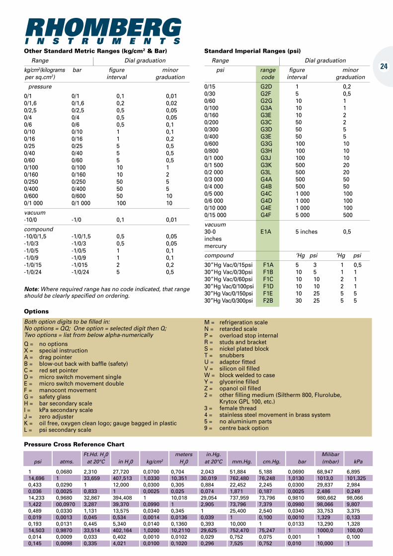
Other Standard Metric Ranges (kg/cm2 & Bar)
Range l Dial graduation
kg/cm2(kilograms bar figure minor per sq.cm2) interval graduation
pressure
0/1 0/1 0,1 0,01 0/1,6 0/1,6 0,2 0,02 0/2,5 0/2,5 0,5 0,05 0/4 0/4 0,5 0,05 0/6 0/6 0,5 0,1 0/10 0/10 1 0,1 0/16 0/16 1 0,2 0/25 0/25 5 0,5 0/40 0/40 5 0,5 0/60 0/60 5 0,5 0/100 0/100 10 1 0/160 0/160 10 2 0/250 0/250 50 5 0/400 0/400 50 5 0/600 0/600 50 10 0/1 000 0/1 000 100 10
vacuum -10/0 -1/0 0,1 0,01
compound -10/0/1,5 -1/0/1,5 0,5 0,05 -1/0/3 -1/0/3 0,5 0,05 -1/0/5 -1/0/5 1 0,1 -1/0/9 -1/0/9 1 0,1 -1/0/15 -1/015 2 0,2 -1/0/24 -1/0/24 5 0,5
Standard Imperial Ranges (psi)
Range l Dial graduation
psi range figure minor code interval graduation
0/15 G2D 1 0,2 0/30 G2F 5 0,5 0/60 G2G 10 1 0/100 G3A 10 1 0/160 G3E 10 2 0/200 G3C 50 2 0/300 G3D 50 5 0/400 G3E 50 5 0/600 G3G 100 10 0/800 G3H 100 10 0/1 000 G3J 100 10 0/1 500 G3K 500 20 0/2 000 G3L 500 20 0/3 000 G4A 500 50 0/4 000 G4B 500 50 0/5 000 G4C 1 000 100 0/6 000 G4D 1 000 100 0/10 000 G4E 1 000 100 0/15 000 G4F 5 000 500
vacuum 30-0 E1A 5 inches 0,5 inches mercury
compound ‘Hg psi ‘Hg psi
30”Hg Vac/0/15psi F1A 5 3 1 0,5 30”Hg Vac/0/30psi F1B 10 5 1 1 30”Hg Vac/0/60psi F1C 10 10 2 1 30”Hg Vac/0/100psi F1D 10 10 2 1 30”Hg Vac/0/150psi F1E 10 25 5 5 30”Hg Vac/0/300psi F2B 30 25 5 5
Note: Where required range has no code indicated, that range should be clearly specified on ordering.
Options
Both option digits to be filled in: No options = QQ; One option = selected digit then Q; Two options = list from below alpha-numericallyQ = no options X = special instruction A = drag pointer B = blow-out back with baffle (safety) C = red set pointer D = micro switch movement single E = micro switch movement double F = manocont movement G = safety glass H = bar secondary scale I = kPa secondary scale J = zero adjuster K = oil free, oxygen clean logo; gauge bagged in plastic L = psi secondary scale
M = refrigeration scale N = retarded scale P = overload stop internal R = studs and bracket S = nickel plated block T = snubbers U = adaptor fitted V = silicon oil filled W = block welded to case Y = glycerine filled Z = opanol oil filled 2 = other filling medium (Siltherm 800, Flurolube, Krytox GPL 100, etc.) 3 = female thread 4 = stainless steel movement in brass system 5 = no aluminium parts 9 = centre back option
Pressure Cross Reference Chart
Ft.Hd. H20 meters in.Hg. Milibar psi atms. at 20°C in H20 kg/cm2 H20 at 20°C mm.Hg. cm.Hg. bar (mbar) kPa
1 0,0680 2,310 27,720 0,0700 0,704 2,043 51,884 5,188 0,0690 68,947 6,895 14,696 1 33,659 407,513 1,0330 10,351 30,019 762,480 76,248 1,0130 1013,0 101,325 0,433 0,0290 1 12,000 0,0300 0,305 0,884 22,452 2,245 0,0300 29,837 2,984 0,036 0,0025 0,833 1 0,0025 0,025 0,074 1,871 0,187 0,0025 2,486 0,249 14,233 0,9680 32,867 394,408 1 10,018 29,054 737,959 73,796 0,9810 980,662 98,066 1,422 00,0970 3,287 39,370 0,0990 1 2,905 73,796 7,379 0,0980 98,066 9,807 0,489 0,0330 1,131 13,575 0,0340 0,345 1 25,400 2,540 0,0340 33,753 3,375 0,019 0,0013 0,045 0,534 0,0014 0,0136 0,039 1 0,100 0,0010 1,329 0,133 0,193 0,0131 0,445 5,340 0,0140 0,1360 0,393 10,000 1 0,0133 13,290 1,328 14,503 0,9870 33,514 402,164 1,0200 10,2110 29,625 752,470 75,247 1 1000,0 100,00 0,014 0,0009 0,033 0,402 0,0010 0,0102 0,029 0,752 0,075 0,001 1 0,100 0,145 0,0098 0,335 4,021 0,0100 0,1020 0,296 7,525 0,752 0,010 10,000 1
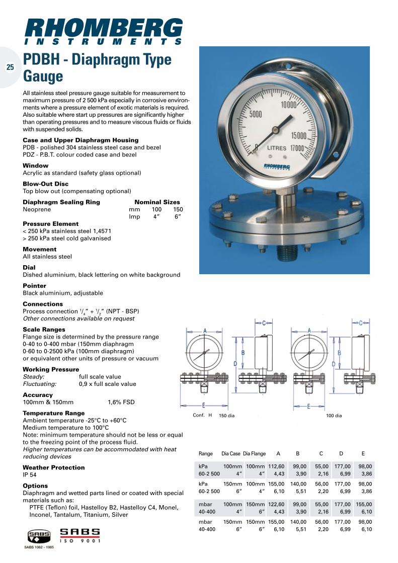
PDBH - Diaphragm Type Gauge
Conf. H 100 dia150 dia
Range Dia Case Dia Flange A B C D E
kPa 100mm 100mm 112,60 99,00 55,00 177,00 98,00 60-2 500 4” 4” 4,43 3,90 2,16 6,99 3,86
kPa 150mm 100mm 155,00 140,00 56,00 177,00 98,00 60-2 500 6” 4” 6,10 5,51 2,20 6,99 3,86
mbar 100mm 150mm 122,60 99,00 55,00 177,00 155,00 40-400 4” 6” 4,43 3,90 2,16 6,99 6,10
mbar 150mm 150mm 155,00 140,00 56,00 177,00 98,00 40-400 6” 6” 6,10 5,51 2,20 6,99 6,10
All stainless steel pressure gauge suitable for measurement to maximum pressure of 2 500 kPa especially in corrosive environ-ments where a pressure element of exotic materials is required. Also suitable where start up pressures are significantly higher than operating pressures and to measure viscous fluids or fluids with suspended solids.
Case and Upper Diaphragm Housing PDB - polished 304 stainless steel case and bezel PDZ - P.B.T. colour coded case and bezel
Window Acrylic as standard (safety glass optional)
Blow-Out Disc Top blow out (compensating optional)
Diaphragm Sealing Ring Nominal Sizes Neoprene mm 100 150 lmp 4” 6”Pressure Element < 250 kPa stainless steel 1,4571 > 250 kPa steel cold galvanised
Movement All stainless steel
Dial Dished aluminium, black lettering on white background
Pointer Black aluminium, adjustable
Connections Process connection 1/4” + 1/2” (NPT - BSP) Other connections available on request
Scale Ranges Flange size is determined by the pressure range 0-40 to 0-400 mbar (150mm diaphragm 0-60 to 0-2500 kPa (100mm diaphragm) or equivalent other units of pressure or vacuum
Working Pressure Steady: full scale value Fluctuating: 0,9 x full scale value
Accuracy 100mm & 150mm 1,6% FSD
Temperature Range Ambient temperature -25°C to +60°C Medium temperature to 100°C Note: minimum temperature should not be less or equal to the freezing point of the process fluid. Higher temperatures can be accommodated with heat reducing devices
Weather Protection IP 54
Options Diaphragm and wetted parts lined or coated with special materials such as: PTFE (Teflon) foil, Hastelloy B2, Hastelloy C4, Monel, Inconel, Tantalum, Titanium, Silver
25
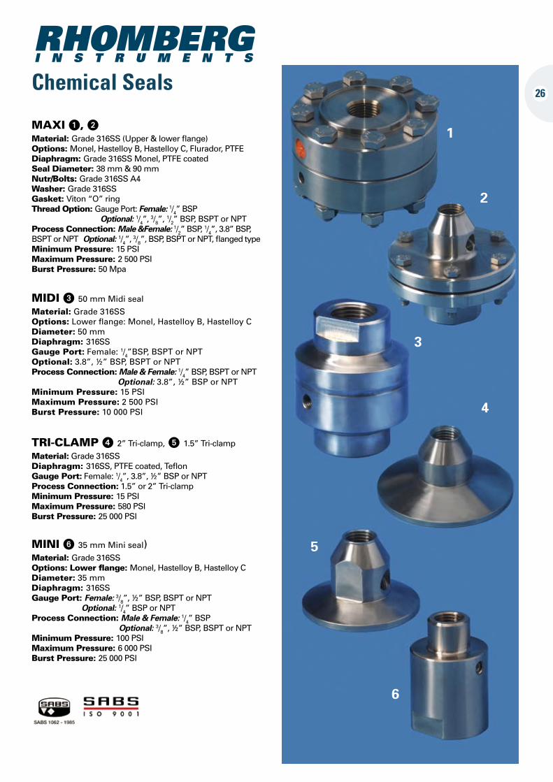
26Chemical Seals
MIDI 3 50 mm Midi seal
Material: Grade 316SSOptions: Lower flange: Monel, Hastelloy B, Hastelloy CDiameter: 50 mmDiaphragm: 316SSGauge Port: Female: 1/4”BSP, BSPT or NPTOptional: 3.8”, ½” BSP, BSPT or NPTProcess Connection: Male & Female: 1/4” BSP, BSPT or NPT Optional: 3.8”, ½” BSP or NPTMinimum Pressure: 15 PSIMaximum Pressure: 2 500 PSIBurst Pressure: 10 000 PSI
TRI-CLAMP 4 2” Tri-clamp, 5 1.5” Tri-clamp
Material: Grade 316SSDiaphragm: 316SS, PTFE coated, TeflonGauge Port: Female: 1/4”, 3.8”, ½” BSP or NPTProcess Connection: 1.5” or 2” Tri-clampMinimum Pressure: 15 PSIMaximum Pressure: 580 PSIBurst Pressure: 25 000 PSI
MINI 6 35 mm Mini seal)Material: Grade 316SSOptions: Lower flange: Monel, Hastelloy B, Hastelloy CDiameter: 35 mmDiaphragm: 316SSGauge Port: Female: 3/8”, ½” BSP, BSPT or NPT Optional: 1/4” BSP or NPTProcess Connection: Male & Female: 1/4” BSP Optional: 3/8”, ½” BSP, BSPT or NPTMinimum Pressure: 100 PSIMaximum Pressure: 6 000 PSIBurst Pressure: 25 000 PSI
MAXI 1, 2Material: Grade 316SS (Upper & lower flange)Options: Monel, Hastelloy B, Hastelloy C, Flurador, PTFEDiaphragm: Grade 316SS Monel, PTFE coated Seal Diameter: 38 mm & 90 mm Nutr/Bolts: Grade 316SS A4Washer: Grade 316SSGasket: Viton “O” ringThread Option: Gauge Port: Female: 1/4” BSP Optional: 1/4”, 3/8”, 1/2” BSP, BSPT or NPTProcess Connection: Male &Female: 1/2” BSP, 1/4”, 3.8” BSP, BSPT or NPT Optional: 1/4”, 3/8”, BSP, BSPT or NPT, flanged typeMinimum Pressure: 15 PSIMaximum Pressure: 2 500 PSIBurst Pressure: 50 Mpa
1
2
3
4
5
6
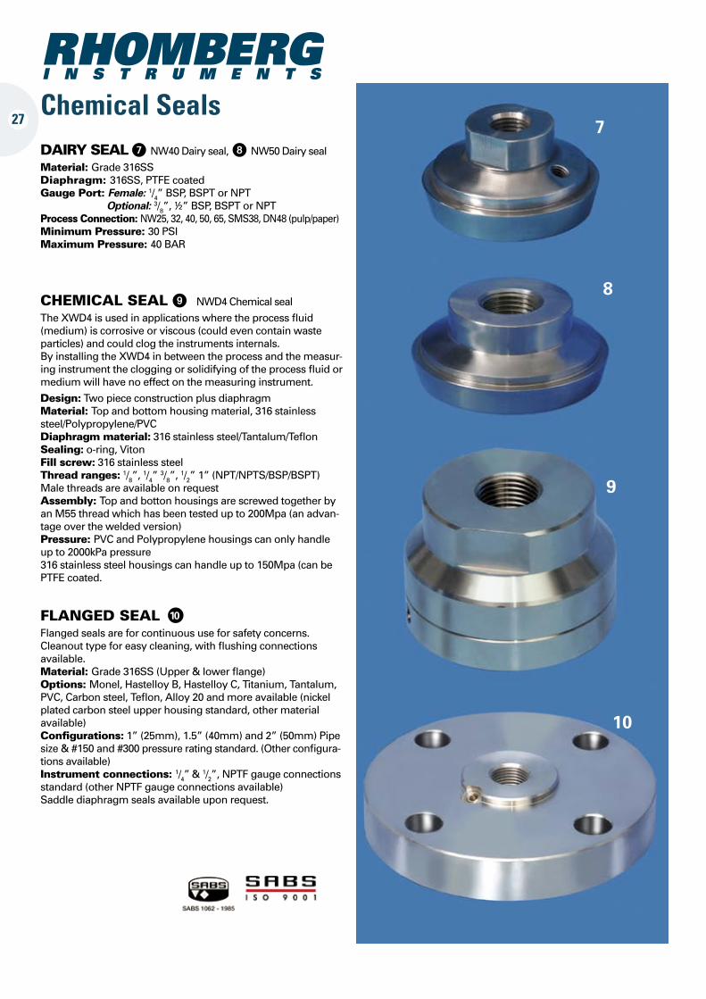
CHEMICAL SEAL 9 NWD4 Chemical seal The XWD4 is used in applications where the process fluid (medium) is corrosive or viscous (could even contain waste particles) and could clog the instruments internals.By installing the XWD4 in between the process and the measur-ing instrument the clogging or solidifying of the process fluid or medium will have no effect on the measuring instrument.
Design: Two piece construction plus diaphragmMaterial: Top and bottom housing material, 316 stainless steel/Polypropylene/PVCDiaphragm material: 316 stainless steel/Tantalum/TeflonSealing: o-ring, VitonFill screw: 316 stainless steelThread ranges: 1/8”, 1/4” 3/8”, 1/2” 1” (NPT/NPTS/BSP/BSPT)Male threads are available on requestAssembly: Top and botton housings are screwed together by an M55 thread which has been tested up to 200Mpa (an advan-tage over the welded version)Pressure: PVC and Polypropylene housings can only handle up to 2000kPa pressure316 stainless steel housings can handle up to 150Mpa (can be PTFE coated.
Chemical Seals27
FLANGED SEAL 10
Flanged seals are for continuous use for safety concerns. Cleanout type for easy cleaning, with flushing connections available.Material: Grade 316SS (Upper & lower flange)Options: Monel, Hastelloy B, Hastelloy C, Titanium, Tantalum, PVC, Carbon steel, Teflon, Alloy 20 and more available (nickel plated carbon steel upper housing standard, other material available)Configurations: 1” (25mm), 1.5” (40mm) and 2” (50mm) Pipe size & #150 and #300 pressure rating standard. (Other configura-tions available)Instrument connections: 1/4” & 1/2”, NPTF gauge connections standard (other NPTF gauge connections available)Saddle diaphragm seals available upon request.
7
8
9
10
DAIRY SEAL 7 NW40 Dairy seal, 8 NW50 Dairy seal
Material: Grade 316SSDiaphragm: 316SS, PTFE coatedGauge Port: Female: 1/4” BSP, BSPT or NPT Optional: 3/8”, ½” BSP, BSPT or NPTProcess Connection: NW25, 32, 40, 50, 65, SMS38, DN48 (pulp/paper)Minimum Pressure: 30 PSIMaximum Pressure: 40 BAR
28
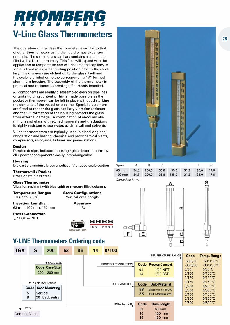
Specs A B C D E F G
63 mm 34,8 200,0 35,8 95,0 31,2 95,0 17,6 100 mm 34,8 200,0 35,8 135,0 31,2 135,0 17,6
Dimensions in mm
V-Line Glass Thermometers
V-LINE Thermometers Ordering code TGX S 200 63 BB 14 0/100
Code Temp. Range -50/0/30 -50/0/30°C -30/0/50 -30/0/50°C 0/50 0/50°C 0/100 0/100°C 0/120 0/120°C 0/160 0/160°C 0/200 0/200°C 0/300 0/300°C 0/400 0/400°C 0/500 0/500°C 0/600 0/600°C
TEMPERATURE RANGE
Code Process Connect. 04 1/2” NPT 14 1/2” BSP
PROCESS CONNECTION
Code Bulb Material BB Brass (up to 300°C SS 316L Stainless steel
BULB MATERIAL
Code Bulb Length 63 63 mm 10 100 mm 15 150 mm
BULB LENGTH
Code Case Size 200 200 mm
CASE SIZE
Code Case Mounting S Vertical B 90° back entry
CASE MOUNTING
Denotes V-Line
TYPE
The operation of the glass thermometer is similar to that of other thermometers using the liquid or gas expansion principle. The sealed glass capillary contains a small bulb filled with a liquid or mercury. This fluid will expand with the application of temperature and will rise into the capillary. A scale is fixed in a corresponding position next to the capil-lary. The divisions are etched on to the glass itself and the scale is printed on to the corresponding “V” formed aluminium housing. The assembly of the thermometer is practical and resistant to breakage if correctly installed.
All components are readily disassembled even on pipelines or tanks holding contents. This is made possible as the pocket or thermowell can be left in place without disturbing the contents of the vessel or pipeline. Special elastomers are fitted to render the glass capillary vibration resistant and the”V” formation of the housing protects the glass from external damage. A combination of anodised alu-minium and glass with etched numerals and graduations is highly resistant to sea water, acids, alkali and solvents.
V-line thermometers are typically used in diesel engines, refrigeration and heating, chemical and petrochemical plants, compressors, ship yards, turbines and power stations.
Design Durable design, indicator housing / glass insert / thermow-ell / pocket / components easily interchangeable
Housing Die cast aluminium; brass anodised, V-shaped scale section
Thermowell / Pocket Brass or stainless steel
Glass Thermometer Vibration resistant with blue spirit or mercury filled columns
Temperature Ranges Stem Configurations -60 up to 600°C Vertical or 90° angle
Insertion Lengths Accuracy63 mm, 100 mm, 150 mm 1%
Press Connection 1/2” BSP or NPT
TBS - Bi-Metal Thermometers
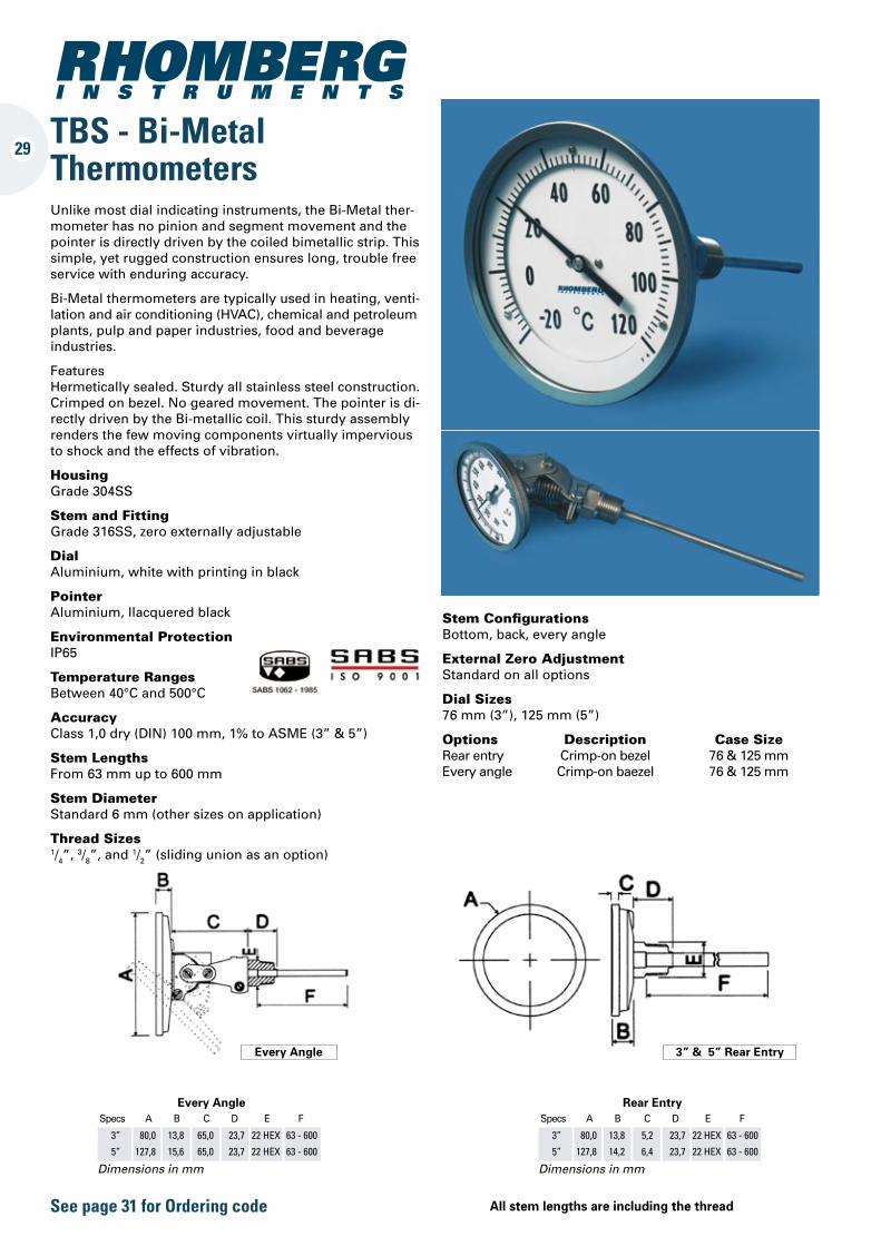
Stem Configurations Bottom, back, every angle
External Zero Adjustment Standard on all options
Dial Sizes 76 mm (3”), 125 mm (5”)
Options Description Case SizeRear entry Crimp-on bezel 76 & 125 mm Every angle Crimp-on baezel 76 & 125 mm
Every AngleSpecs A B C D E F
3” 80,0 13,8 65,0 23,7 22 HEX 63 - 600
5” 127,8 15,6 65,0 23,7 22 HEX 63 - 600
Dimensions in mm
Rear EntrySpecs A B C D E F
3” 80,0 13,8 5,2 23,7 22 HEX 63 - 600
5” 127,8 14,2 6,4 23,7 22 HEX 63 - 600
Dimensions in mm
3” & 5” Rear EntryEvery Angle
Unlike most dial indicating instruments, the Bi-Metal ther-mometer has no pinion and segment movement and the pointer is directly driven by the coiled bimetallic strip. This simple, yet rugged construction ensures long, trouble free service with enduring accuracy.
Bi-Metal thermometers are typically used in heating, venti-lation and air conditioning (HVAC), chemical and petroleum plants, pulp and paper industries, food and beverage industries.
Features Hermetically sealed. Sturdy all stainless steel construction. Crimped on bezel. No geared movement. The pointer is di-rectly driven by the Bi-metallic coil. This sturdy assembly renders the few moving components virtually impervious to shock and the effects of vibration.
Housing Grade 304SS
Stem and Fitting Grade 316SS, zero externally adjustable
Dial Aluminium, white with printing in black
Pointer Aluminium, llacquered black
Environmental Protection IP65
Temperature Ranges Between 40°C and 500°C
Accuracy Class 1,0 dry (DIN) 100 mm, 1% to ASME (3” & 5”)
Stem Lengths From 63 mm up to 600 mm
Stem Diameter Standard 6 mm (other sizes on application)
Thread Sizes 1/4”, 3/8”, and 1/2” (sliding union as an option)
29
See page 31 for Ordering code All stem lengths are including the thread
30
Specs A B C D E F
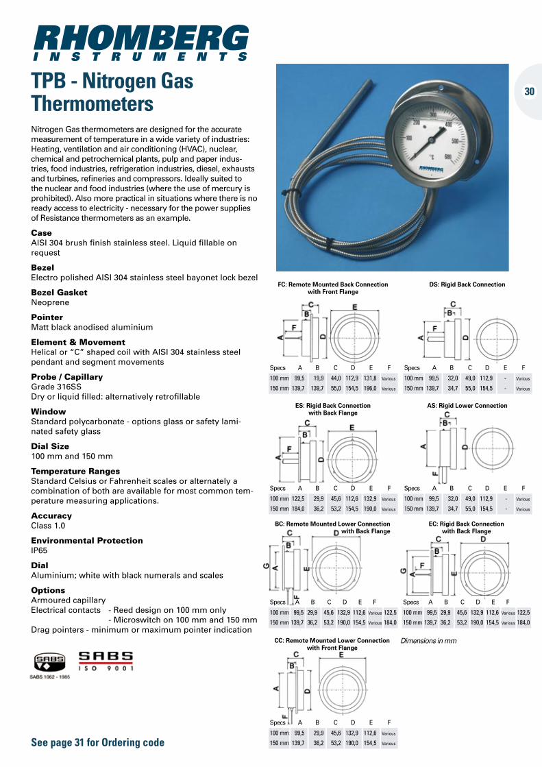
100 mm 99,5 19,9 44,0 112,9 131,8 Various
150 mm 139,7 139,7 55,0 154,5 196,0 Various
FC: Remote Mounted Back Connection with Front Flange
Specs A B C D E F
100 mm 99,5 32,0 49,0 112,9 - Various
150 mm 139,7 34,7 55,0 154,5 - Various
DS: Rigid Back Connection
Specs A B C D E F
100 mm 122,5 29,9 45,6 112,6 132,9 Various
150 mm 184,0 36,2 53,2 154,5 190,0 Various
ES: Rigid Back Connection with Back Flange
Specs A B C D E F
100 mm 99,5 32,0 49,0 112,9 - Various
150 mm 139,7 34,7 55,0 154,5 - Various
AS: Rigid Lower Connection
TPB - Nitrogen Gas Thermometers
BC: Remote Mounted Lower Connection with Back Flange
EC: Rigid Back Connection with Back Flange
Specs A B C D E F
100 mm 99,5 29,9 45,6 132,9 112,6 Various
150 mm 139,7 36,2 53,2 190,0 154,5 Various
CC: Remote Mounted Lower Connection with Front Flange
Specs A B C D E F
100 mm 99,5 29,9 45,6 132,9 112,6 Various 122,5
150 mm 139,7 36,2 53,2 190,0 154,5 Various 184,0
Specs A B C D E F
100 mm 99,5 29,9 45,6 132,9 112,6 Various 122,5
150 mm 139,7 36,2 53,2 190,0 154,5 Various 184,0
Dimensions in mm
Nitrogen Gas thermometers are designed for the accurate measurement of temperature in a wide variety of industries: Heating, ventilation and air conditioning (HVAC), nuclear, chemical and petrochemical plants, pulp and paper indus-tries, food industries, refrigeration industries, diesel, exhausts and turbines, refineries and compressors. Ideally suited to the nuclear and food industries (where the use of mercury is prohibited). Also more practical in situations where there is no ready access to electricity - necessary for the power supplies of Resistance thermometers as an example.
Case AISI 304 brush finish stainless steel. Liquid fillable on request
Bezel Electro polished AISI 304 stainless steel bayonet lock bezel
Bezel Gasket Neoprene
Pointer Matt black anodised aluminium
Element & Movement Helical or “C” shaped coil with AISI 304 stainless steel pendant and segment movements
Probe / Capillary Grade 316SS Dry or liquid filled: alternatively retrofillable
Window Standard polycarbonate - options glass or safety lami-nated safety glass
Dial Size 100 mm and 150 mm
Temperature Ranges Standard Celsius or Fahrenheit scales or alternately a combination of both are available for most common tem-perature measuring applications.
Accuracy Class 1.0
Environmental Protection IP65
Dial Aluminium; white with black numerals and scales
Options Armoured capillary Electrical contacts - Reed design on 100 mm only - Microswitch on 100 mm and 150 mm Drag pointers - minimum or maximum pointer indication
See page 31 for Ordering code
31
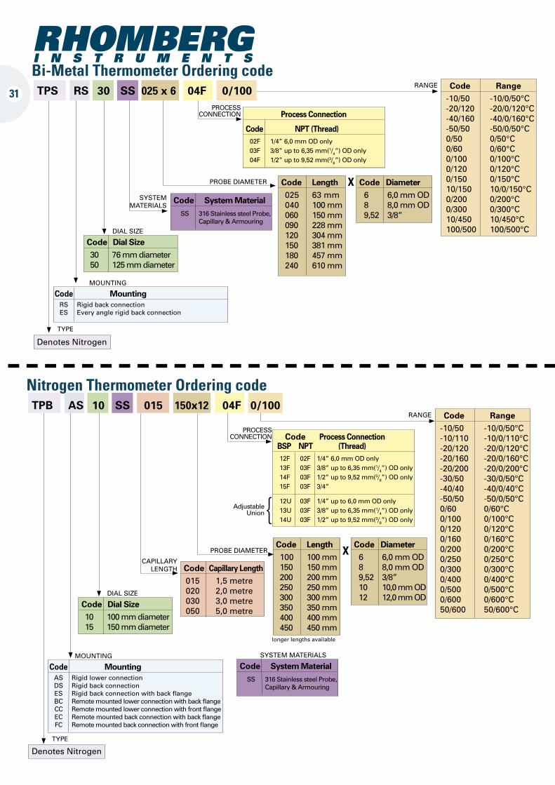
Code Dial Size 10 100 mm diameter 15 150 mm diameter
DIAL SIZE
Denotes Nitrogen
TYPE
Code Range -10/50 -10/0/50°C -10/110 -10/0/110°C -20/120 -20/0/120°C -20/160 -20/0/160°C -20/200 -20/0/200°C -30/50 -30/0/50°C -40/40 -40/0/40°C -50/50 -50/0/50°C 0/60 0/60°C 0/100 0/100°C 0/120 0/120°C 0/160 0/160°C 0/200 0/200°C 0/250 0/250°C 0/300 0/300°C 0/400 0/400°C 0/500 0/500°C 0/600 0/600°C 50/600 50/600°C
RANGE
Code Process Connection BSP NPT (Thread) 12F 02F 1/4” 6,0 mm OD only 13F 03F 3/8” up to 6,35 mm(1/4”) OD only 14F 03F 1/2” up to 9,52 mm(3/8”) OD only 15F 03F 3/4”
12U 03F 1/4” up to 6,0 mm OD only 13U 03F 3/8” up to 6,35 mm(1/4”) OD only 14U 03F 1/2” up to 9,52 mm(3/8”) OD only
PROCESS CONNECTION
Code Length 100 100 mm 150 150 mm 200 200 mm 250 250 mm 300 300 mm 350 350 mm 400 400 mm 450 450 mm
PROBE DIAMETER
Code Capillary Length 015 1,5 metre 020 2,0 metre 030 3,0 metre 050 5,0 metre
CAPILLARY LENGTH
Code Mounting AS Rigid lower connection DS Rigid back connection ES Rigid back connection with back flange BC Remote mounted lower connection with back flange CC Remote mounted lower connection with front flange EC Remote mounted back connection with back flange FC Remote mounted back connection with front flange
MOUNTING
Code System Material SS 316 Stainless steel Probe, Capillary & Armouring
SYSTEM MATERIALS
Code Diameter 6 6,0 mm OD 8 8,0 mm OD 9,52 3/8” 10 10,0 mm OD 12 12,0 mm OD
X
Adjustable Union{
Nitrogen Thermometer Ordering code TPB AS 10 SS 015 150x12 04F 0/100
Code Range -10/50 -10/0/50°C -20/120 -20/0/120°C -40/160 -40/0/160°C -50/50 -50/0/50°C 0/50 0/50°C 0/60 0/60°C 0/100 0/100°C 0/120 0/120°C 0/150 0/150°C 10/150 10/0/150°C 0/200 0/200°C 0/300 0/300°C 10/450 10/450°C 100/500 100/500°C
RANGE
Code Dial Size 30 76 mm diameter 50 125 mm diameter
DIAL SIZE
Denotes Nitrogen
TYPE
Process Connection
Code NPT (Thread) 02F 1/4” 6,0 mm OD only 03F 3/8” up to 6,35 mm(1/4”) OD only 04F 1/2” up to 9,52 mm(3/8”) OD only
PROCESS CONNECTION
Code Length 025 63 mm 040 100 mm 060 150 mm 090 228 mm 120 304 mm 150 381 mm 180 457 mm 240 610 mm
PROBE DIAMETER
SYSTEM MATERIALS
Code Mounting RS Rigid back connection ES Every angle rigid back connection
MOUNTING
Code System Material SS 316 Stainless steel Probe, Capillary & Armouring
Code Diameter 6 6,0 mm OD 8 8,0 mm OD 9,52 3/8”
X
longer lengths available
Bi-Metal Thermometer Ordering code TPS RS 30 SS 025 x 6 04F 0/100
116
46 50 20
Ø22.5 Ø26.6 Ø20.9
12943
27
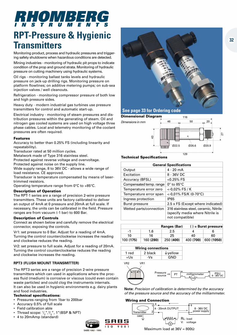
Technical Specifications
General Specifications Output 4 - 20 mA Excitation 8 - 36V DC Accuracy (BFSL) <0.25% FS Compensated temp. range 0° to 85°C Temperature error zero <-0,02% FS / K Temperature error span <-0,01% FS/K (0-70°C) Ingress protection IP65 Burst pressure 2.5 x FS (Except where indicated) Wetted parts/connection 316 stainless steel, ceramic, Nitrile (specify media where Nitrile is not compatible)
Ranges (Bar) -1 1.6 2.5 4 6 10 16 25 40 60 100 (175) 160 (280) 250 (400) 400 (700) 600 (1050)
( ) = Burst pressure
Wiring connections 1 red 2 black I yellow +Us -Vs GND
32RPT-Pressure & HygienicTransmitters
Dimensions in mm
Dimensional Diagram
Note: Precision of calibration is determined by the accuracy of the pressure source and the accuracy of the milliammeter.
VR2 VR1
Pressure source PT milliammeter
mA
PSU 8 - 36V DC
Maximum load at 36V = 800Ω
Transmitter case
4 - 20mA OUTPUT 8 - 36V DC power supply
RL: load V: voltage
Wiring and Connection1
2
Monitoring product, process and hydraulic pressures and trigger-ing safety shutdowns when hazardous conditions are detected.
Mining industries - monitoring of hydraulic pit props to indicate condition of the prop and ground strata. Monitoring of hydraulic pressure on cutting machinery using hydraulic systems.
Oil rigs - monitoring ballast tanks levels and hydraulic pressure on jack-up drilling rigs. Monitoring pressure on platform flowlines; on additive metering pumps; on sub-sea injection valves / well cleanouts.
Refrigeration - monitoring compressor pressure of both low and high pressure sides.
Heavy duty - modern industrial gas turbines use pressure transmitters for control and automatic start-up.
Electrical industry - monitoring of steam pressures and dis-tribution pressures within the generating of steam. Oil and nitrogen gas cooled systems are used on high voltage three phase cables. Local and telemetry monitoring of the coolant pressures are often required.
FeaturesAccuracy to better than 0.25% FS (including linearity and repeatability). Transducer rated at 50 million cycles. Metalwork made of Type 316 stainless steel. Protected against reverse voltage and overvoltage. Protected against noise on the supply line. Wide supply range, 8 to 36V DC - allows a wide range of load resistance. CE approved. Transducer is temperature compensated by means of laser-trimmed resistors. Operating temperature range from 0°C to +85°C.
Description of OperationThe RPT-1 series are a range of precision 2-wire pressure transmitters. These units are factory calibrated to deliver an output of 4mA at 0 pressure and 20mA at full scale. If necessary, the units can be calibrated in the field. Pressure ranges are from vacuum (-1 bar) to 600 Bar.
Description of ControlsConnect as shown below and carefully remove the electrical connector, exposing the controls.
Vr1: set pressure to 0 Bar. Adjust for a reading of 4mA. Turning the control counterclockwise increases the reading and clockwise reduces the reading.
Vr2: set pressure to full scale. Adjust for a reading of 20mA. Turning the control counterclockwise reduces the reading and clockwise increases the reading.
See page 33 for Ordering code
RPT3 (FLUSH MOUNT TRANSMITTER)
The RPT3 series are a range of precision 2-wire pressure transmitters which can used in applications where the proc-ess fluid (medium) is corrosive or viscous (could even contain waste particles) and could clog the instruments internals.It can also be used in hygienic environments e.g. dairy plants and food industries.Technical specifications:• Pressuresrangingfrom1barto200bar• Accuracy0.5%offullscale• Fieldcalibrationable• Threadscope:1/2”,3/4”, 1”(BSP & NPT)• 4to20mAmp(standard)
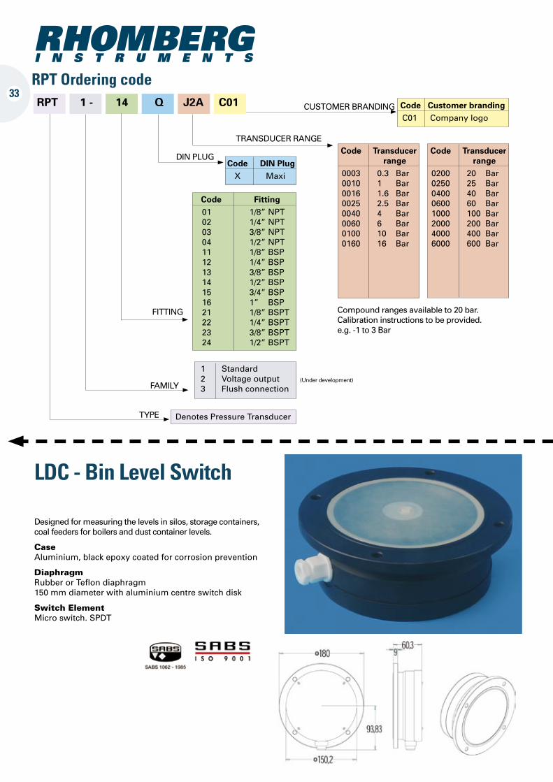
LDC - Bin Level Switch
Designed for measuring the levels in silos, storage containers, coal feeders for boilers and dust container levels.
Case Aluminium, black epoxy coated for corrosion prevention
Diaphragm Rubber or Teflon diaphragm 150 mm diameter with aluminium centre switch disk
Switch Element Micro switch. SPDT
33RPT Ordering code RPT 1 - 14 Q J2A C01 Code Customer branding
C01 Company logo
Code Fitting 01 1/8” NPT 02 1/4” NPT 03 3/8” NPT 04 1/2” NPT 11 1/8” BSP 12 1/4” BSP 13 3/8” BSP 14 1/2” BSP 15 3/4” BSP 16 1” BSP 21 1/8” BSPT 22 1/4” BSPT 23 3/8” BSPT 24 1/2” BSPT
Code Transducer range 0003 0.3 Bar 0010 1 Bar 0016 1.6 Bar 0025 2.5 Bar 0040 4 Bar 0060 6 Bar 0100 10 Bar 0160 16 Bar
1 Standard 2 Voltage output 3 Flush connection
Denotes Pressure Transducer
CUSTOMER BRANDING
FITTING
TRANSDUCER RANGE
Code DIN Plug X Maxi
DIN PLUG
FAMILY
TYPE
Compound ranges available to 20 bar. Calibration instructions to be provided. e.g. -1 to 3 Bar
(Under development)
Code Transducer range 0200 20 Bar 0250 25 Bar 0400 40 Bar 0600 60 Bar 1000 100 Bar 2000 200 Bar 4000 400 Bar 6000 600 Bar
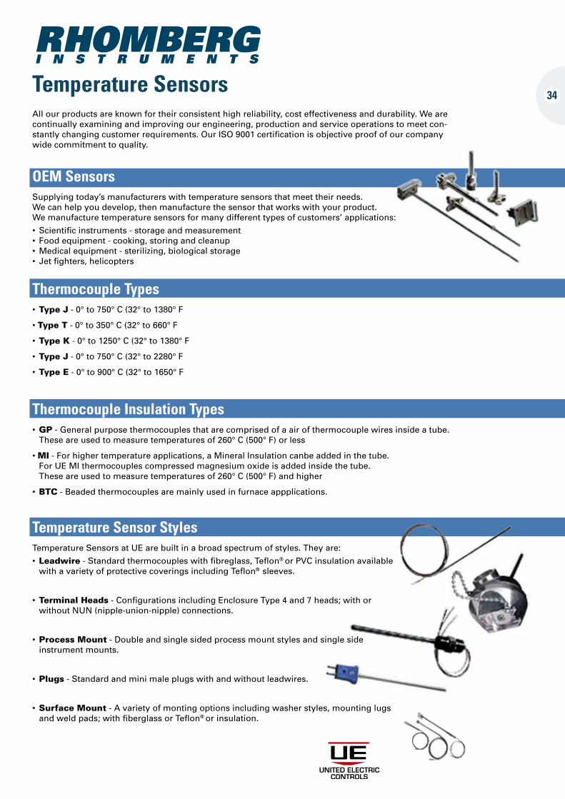
Temperature SensorsAll our products are known for their consistent high reliability, cost effectiveness and durability. We are continually examining and improving our engineering, production and service operations to meet con-stantly changing customer requirements. Our ISO 9001 certification is objective proof of our company wide commitment to quality.
OEM SensorsSupplying today’s manufacturers with temperature sensors that meet their needs. We can help you develop, then manufacture the sensor that works with your product. We manufacture temperature sensors for many different types of customers’ applications:
• Scientificinstruments-storageandmeasurement • Foodequipment-cooking,storingandcleanup •Medicalequipment-sterilizing,biologicalstorage • Jetfighters,helicopters
Thermocouple Types•Type J - 0° to 750° C (32° to 1380° F
•Type T - 0° to 350° C (32° to 660° F
•Type K - 0° to 1250° C (32° to 1380° F
•Type J - 0° to 750° C (32° to 2280° F
•Type E - 0° to 900° C (32° to 1650° F
Thermocouple Insulation Types•GP - General purpose thermocouples that are comprised of a air of thermocouple wires inside a tube. These are used to measure temperatures of 260° C (500° F) or less
•MI - For higher temperature applications, a Mineral Insulation canbe added in the tube. For UE MI thermocouples compressed magnesium oxide is added inside the tube. These are used to measure temperatures of 260° C (500° F) and higher
•BTC - Beaded thermocouples are mainly used in furnace appplications.
Temperature Sensor StylesTemperature Sensors at UE are built in a broad spectrum of styles. They are:
•Leadwire - Standard thermocouples with fibreglass, Teflon® or PVC insulation available with a variety of protective coverings including Teflon® sleeves.
•Terminal Heads - Configurations including Enclosure Type 4 and 7 heads; with or without NUN (nipple-union-nipple) connections.
•Process Mount - Double and single sided process mount styles and single side instrument mounts.
•Plugs - Standard and mini male plugs with and without leadwires.
•Surface Mount - A variety of monting options including washer styles, mounting lugs and weld pads; with fiberglass or Teflon® or insulation.
34
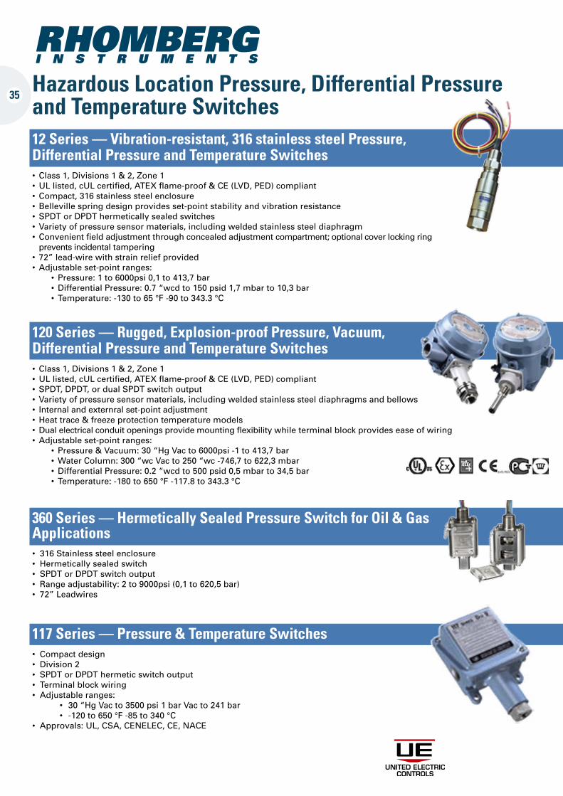
32Hazardous Location Pressure, Differential Pressure and Temperature Switches12 Series — Vibration-resistant, 316 stainless steel Pressure, Differential Pressure and Temperature Switches• Class1,Divisions1&2,Zone1 •ULlisted,cULcertified,ATEXflame-proof&CE(LVD,PED)compliant • Compact,316stainlesssteelenclosure • Bellevillespringdesignprovidesset-pointstabilityandvibrationresistance • SPDTorDPDThermeticallysealedswitches • Varietyofpressuresensormaterials,includingweldedstainlesssteeldiaphragm • Convenientfieldadjustmentthroughconcealedadjustmentcompartment;optionalcoverlockingring prevents incidental tampering • 72”lead-wirewithstrainreliefprovided •Adjustableset-pointranges: • Pressure:1to6000psi0,1to413,7bar •DifferentialPressure:0.7“wcdto150psid1,7mbarto10,3bar • Temperature:-130to65°F-90to343.3°C
120 Series — Rugged, Explosion-proof Pressure, Vacuum, Differential Pressure and Temperature Switches• Class1,Divisions1&2,Zone1 •ULlisted,cULcertified,ATEXflame-proof&CE(LVD,PED)compliant • SPDT,DPDT,ordualSPDTswitchoutput • Varietyofpressuresensormaterials,includingweldedstainlesssteeldiaphragmsandbellows • Internalandexternralset-pointadjustment •Heattrace&freezeprotectiontemperaturemodels •Dualelectricalconduitopeningsprovidemountingflexibilitywhileterminalblockprovideseaseofwiring •Adjustableset-pointranges: • Pressure&Vacuum:30“HgVacto6000psi-1to413,7bar •WaterColumn:300“wcVacto250“wc-746,7to622,3mbar •DifferentialPressure:0.2“wcdto500psid0,5mbarto34,5bar • Temperature:-180to650°F-117.8to343.3°C
360 Series — Hermetically Sealed Pressure Switch for Oil & Gas Applications• 316Stainlesssteelenclosure • Hermeticallysealedswitch • SPDTorDPDTswitchoutput • Rangeadjustability:2to9000psi(0,1to620,5bar) • 72”Leadwires
117 Series — Pressure & Temperature Switches • Compactdesign • Division2 • SPDTorDPDThermeticswitchoutput • Terminalblockwiring • Adjustableranges: • 30“HgVacto3500psi1barVacto241bar • -120to650°F-85to340°C • Approvals:UL,CSA,CENELEC,CE,NACE
35
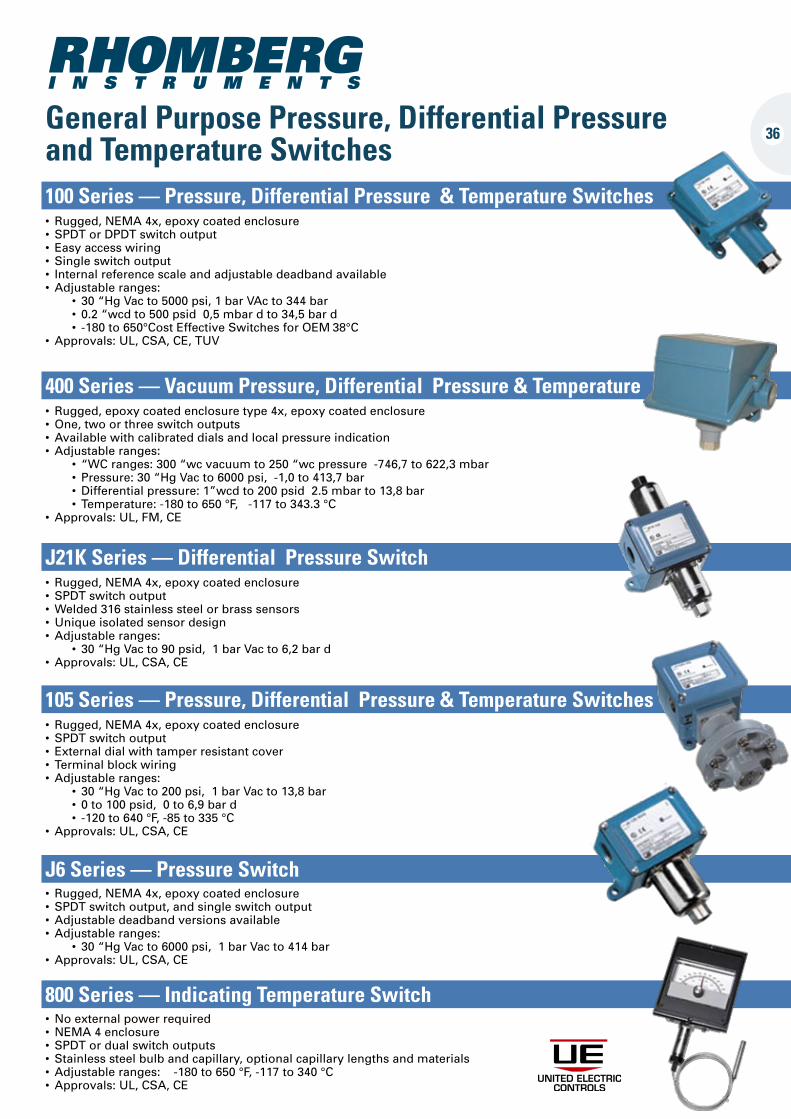
General Purpose Pressure, Differential Pressure and Temperature Switches100 Series — Pressure, Differential Pressure & Temperature Switches• Rugged,NEMA4x,epoxy coated enclosure • SPDTorDPDTswitchoutput • Easyaccesswiring • Singleswitchoutput • Internalreferencescaleandadjustabledeadbandavailable •Adjustableranges: • 30“HgVacto5000psi,1barVActo344bar • 0.2“wcdto500psid0,5mbardto34,5bard • -180to650°CostEffectiveSwitchesforOEM38°C •Approvals:UL,CSA,CE,TUV
400 Series — Vacuum Pressure, Differential Pressure & Temperature• Rugged,epoxycoatedenclosure type 4x, epoxy coated enclosure •One,twoorthreeswitchoutputs •Availablewithcalibrateddialsandlocalpressureindication •Adjustableranges: • “WCranges:300“wcvacuumto250“wcpressure-746,7to622,3mbar • Pressure:30“HgVacto6000psi,-1,0to413,7bar •Differentialpressure:1”wcdto200psid2.5mbarto13,8bar • Temperature:-180to650°F,-117to343.3°C •Approvals:UL,FM,CE
J21K Series — Differential Pressure Switch• Rugged,NEMA4x,epoxycoated enclosure • SPDTswitchoutput •Welded316stainlesssteelorbrasssensors •Uniqueisolatedsensordesign •Adjustableranges: • 30“HgVacto90psid,1barVacto6,2bard •Approvals:UL,CSA,CE
105 Series — Pressure, Differential Pressure & Temperature Switches• Rugged,NEMA4x,epoxycoatedenclosure • SPDTswitchoutput • Externaldialwithtamperresistantcover • Terminalblockwiring •Adjustableranges: • 30“HgVacto200psi,1barVacto13,8bar • 0to100psid,0to6,9bard • -120to640°F,-85to335°C •Approvals:UL,CSA,CE
J6 Series — Pressure Switch• Rugged,NEMA4x,epoxycoatedenclosure • SPDTswitchoutput,andsingleswitchoutput •Adjustabledeadbandversionsavailable •Adjustableranges: • 30“HgVacto6000psi,1barVacto414bar •Approvals:UL,CSA,CE
800 Series — Indicating Temperature Switch•Noexternalpowerrequired •NEMA4enclosure • SPDTordualswitchoutputs • Stainlesssteelbulbandcapillary,optionalcapillarylengthsandmaterials •Adjustableranges:-180to650°F,-117to340°C •Approvals:UL,CSA,CE
36
37
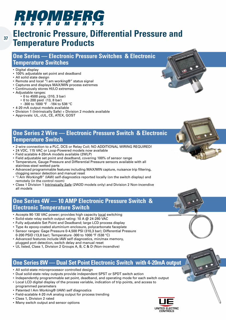
Electronic Pressure, Differential Pressure and Temperature ProductsOne Series — Electronic Pressure Switches & Electronic Temperature Switches•Digitaldisplay • 100%adjustablesetpointanddeadband •Allsolidstatedesign • Remoteandlocal“Iamworking®”statussignal • CapturesanddisplaysMAX/MINprocessextremes • ContinuouslystoresHI/LOextremes •Adjustableranges: • 0to4500psig,(310,3bar) • 0to200psid(13,8bar) • -300to1000°F-184to538°C • 4-20mAoutputmodelsavailable •Division1(IntrinsicallySafe)+Division2modelsavailable •Approvals:UL,cUL,CE,ATEX,GOST
One Series 2 Wire — Electronic Pressure Switch & Electronic Temperature Switch• 2-wireconnectiontoaPLC,DCSorRelayCoil;NOADDITIONALWIRINGREQUIRED! • 24VDC,115VACorLoop-Poweredmodelsnowavailable • Fieldscalable4-20mAmodelsavailable(2WLP) • Fieldadjustablesetpointanddeadband,covering100%ofsensorrange • Temperature,GaugePressureandDifferentialPressuresensorsavailablewithall stainless-steel wetted parts •AdvancedprogrammablefeaturesincludingMAX/MINcapture,nuisancetripfiltering, clogging sensor detection and manual reset • “IAmWorking®”(IAW)self-diagnosticsreportedlocally(ontheswitchdisplay)and remotely (in the control room) • Class1Division1Intrinsically Safe (2W2D models only) and Division 2 Non-incendive all models
One Series 4W — 10 AMP Electronic Pressure Switch & Electronic Temperature Switch•Accepts90-130VACpower;provideshighcapacitylocal switching • Solid-staterelayswitchoutputrating:10A@24-280VAC • FullyadjustableSetPointandDeadband;largeLCDprocessdisplay • Type4xepoxy-coatedaluminiumenclosure,polycarbonatefaceplate • Sensorranges:GagePressure0-4,500PSI(310,3bar);DifferentialPressure 0-200 PSID (13,8 bar); Temperature -300 to 1000 °F (538 °C) •AdvancedfeaturesincludeIAWselfdiagnostics,min/maxmemory, plugged port detection, switch delay and manual reset •ULlisted,Class1,Division2GroupsA,B,C&D(Non-incendive)
One Series 8W — Dual Set Point Electronic Switch with 4-20mA output•Allsolid-statemicroprocessorcontrolleddesign •Dualsolid-staterelayoutputsprovideindependentSPSTorSPDTswitchaction • Independentlyprogrammablesetpoint,deadband,andoperatingmodeforeachswitchoutput • LocalLCDdigitaldisplayoftheprocessvariable,indicationoftrippoints,andaccessto programmed parameters • PatentedIAmWorking®(IAW)selfdiagnostics • Field-scalable4-20mAanalogoutputforprocesstrending • Class1,Division2rated •Manyswitchoutputandsensoroptions
38
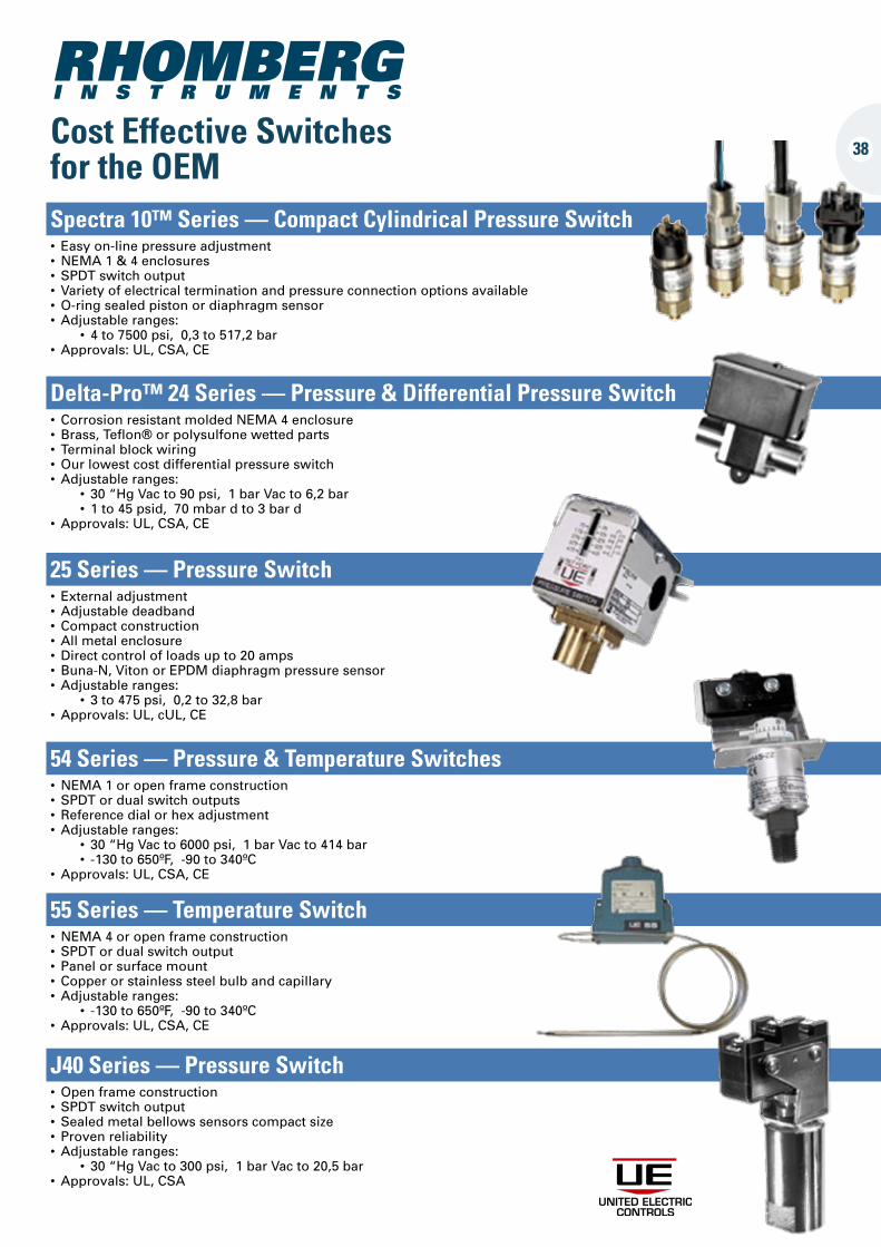
Cost Effective Switches for the OEMSpectra 10™ Series — Compact Cylindrical Pressure Switch• Easyon-linepressureadjustment•NEMA1&4enclosures•SPDTswitchoutput•Varietyofelectricalterminationandpressureconnectionoptionsavailable•O-ringsealedpistonordiaphragmsensor•Adjustableranges: • 4to7500psi,0,3to517,2bar•Approvals:UL,CSA,CE
Delta-Pro™ 24 Series — Pressure & Differential Pressure Switch• CorrosionresistantmoldedNEMA4enclosure•Brass,Teflon®orpolysulfonewettedparts• Terminalblockwiring•Ourlowestcostdifferentialpressureswitch•Adjustableranges: • 30“HgVacto90psi,1barVacto6,2bar • 1to45psid,70mbardto3bard•Approvals:UL,CSA,CE
25 Series — Pressure Switch• Externaladjustment•Adjustabledeadband•Compactconstruction•Allmetalenclosure•Directcontrolofloadsupto20amps•Buna-N,VitonorEPDMdiaphragmpressuresensor•Adjustableranges: • 3to475psi,0,2to32,8bar•Approvals:UL,cUL,CE
54 Series — Pressure & Temperature Switches•NEMA1oropenframeconstruction•SPDTordualswitchoutputs•Referencedialorhexadjustment•Adjustableranges: • 30“HgVacto6000psi,1barVacto414bar • -130to650ºF,-90to340ºC•Approvals:UL,CSA,CE
55 Series — Temperature Switch•NEMA4oropenframeconstruction•SPDTordualswitchoutput• Panelorsurfacemount•Copperorstainlesssteelbulbandcapillary•Adjustableranges: • -130to650ºF,-90to340ºC•Approvals:UL,CSA,CE
J40 Series — Pressure Switch•Openframeconstruction•SPDTswitchoutput•Sealedmetalbellowssensorscompactsize• Provenreliability•Adjustableranges: • 30“HgVacto300psi,1barVacto20,5bar•Approvals:UL,CSA
38
RHOMBERG
SABS 1062 - 1985
Günther Komnick Studio 021 531-7798
RHOMBERG I N S T R U M E N T S
Cnr Barlinka & Muscat Street Saxenburg Park, Blackheath, 7579, Cape TownP.O.Box 1333, Kuils Rivier, 7579, South AfricaTel: +27 021 905-7041/ 2, Fax: +27 (0)21 905-7038
Email:[email protected]
www.rhomberginstruments.co.za