Embed Size (px)
Citation preview
fluids
Article
Rheology of an Inverted Cholesteric Droplet underShear Flow
Federico Fadda 1,2, Giuseppe Gonnella 2, Antonio Lamura 3 and Enzo Orlandini 4
and Adriano Tiribocchi 5,* ID
1 Department of Chemical Engineering, Kyoto University, Kyoto 615-8510, Japan; [email protected] Department of Physics and Sezione INFN Bari, 70126 Bari, Italy; [email protected] Istituto Applicazioni Calcolo, CNR, 70126 Bari, Italy; [email protected] Departmento of Physics and Astronomy and Sezione INFN, Università di Padova, 35131 Padova, Italy;
[email protected] Center for Life Nano Science, IIT, 00161 Roma, Italy* Correspondence: [email protected]; Tel.: +39-064-925-5204
Received: 20 May 2018; Accepted: 28 June 2018; Published: 3 July 2018
Abstract: The dynamics of a quasi two-dimensional isotropic droplet in a cholesteric liquid crystalmedium under symmetric shear flow is studied by lattice Boltzmann simulations. We considera geometry in which the flow direction is along the axis of the cholesteric, as this setup exhibitsa significant viscoelastic response to external stress. We find that the dynamics depends on themagnitude of the shear rate, the anchoring strength of the liquid crystal at the droplet interface andthe chirality. While low shear rate and weak interface anchoring the system shows a non-Newtonianbehavior, a Newtonian-like response is observed at high shear rate and strong interface anchoring.This is investigated both by estimating the secondary flow profile, namely a flow emerging along theout-of-plane direction (absent in fully-Newtonian fluids, such as water) and by monitoring defectformation and dynamics, which significantly alter the rheological response of the system.
Keywords: cholesteric liquid crystals; shear dynamics; emulsions
1. Introduction
Liquid crystals (LC) are fluids often made up of rod-like molecules that can be arranged in a varietyof equilibrium phases, depending on their geometry and reciprocal interaction [1,2]. Of particularrelevance is the cholesteric phase where the local molecular alignment is captured by a unit magnitudedirector field n displaying a natural twist deformation in the direction perpendicular to the molecules.Such liquid crystals can be found in a wide range of biological systems, such as bacterial flagella [3]and DNA molecules in solution [4], and have found increasing application in modern display devices,in which the cholesteric phase results from mixing a nematic liquid crystal (such as E7, Merck KGaA,Darmstadt, Germany) with a chiral dopant. In recent years, much interest has been focused on therealization of liquid crystal-particle composites, a new exciting class of soft material with tunableelastic and electro-optic properties, in which either colloidal particles or droplets of standard fluids aredispersed in an LC phase [5]. The presence of these inclusions induces a disturbance in the directororientation, which typically aligns either tangentially or normally to the surface of the particles.This leads to the formation of a variety of topological defects that mediate long-range anisotropicparticle-particle interactions and stabilize novel ordered structures, such as chain [6,7] and defectglass [8] in nematics or colloidal crystals [9] and isolated clusters [10] in cholesterics, with potentialuse in photonics [11] and in new devices [12].
Recent theoretical and experimental works have investigated the typical defect structures observedat equilibrium when particles are dispersed in cholesteric liquid crystals (CLC) and have shown that
Fluids 2018, 3, 47; doi:10.3390/fluids3030047 www.mdpi.com/journal/fluids
Fluids 2018, 3, 47 2 of 14
these can be controlled by tuning the ratio between the particle size R (typically its radius) and thecholesteric pitch p. For instance, if strong perpendicular (homeotropic) anchoring is set on the surface ofa spherical colloid, one observes either a planar Saturn ring (a circular defect line of half-integer chargelocated around the equator of the particle) if p >> R, or a twisted Saturn rings, wrapping around theparticle, if p < R [13–16]. If, on the other hand, the anchoring is tangential to the surface, the defectpattern ranges from the “boojum” (two surface defects of integer charge located on opposite sides)if R/p is small, to its twisted version if R/p is large enough [15]. A further complication arises when,in place of a solid particle, one considers a deformable liquid droplet. Here, the strength of the interfaceanchoring relative to the elasticity of the LC becomes a crucial parameter to control the droplet shape(in addition to the director pattern near the surface). For instance, one observes either a spherical shapeor a nutshell-like structure if the anchoring strength is respectively weak or strong [17]. So far, mostof the studies have focused on the equilibrium properties of these inclusions [15], and much less isknown when these systems are subject to external perturbations, such as electric and flow fields.
Liquid crystal have long been known as systems that exhibit a rich dynamical response such asshear banding [18–20] and molecular tumbling [1,21,22] when subject to shear flow [1]. This is due tothe complex coupling between hydrodynamics and the director field (known as backflow), a featurethat is even more relevant in a CLC where the inherent three-dimensional twisted arrangement of thedirector field can give rise to striking effects, such as a significant increase in viscosity when subject to ashear flow in the direction of its helix (permeation) [23–25]. Recent simulations on colloidal dispersionsin CLC report, for instance, a violation of the Stokes law when a single particle is dragged parallel tothe cholesteric helix [13], or an induced rotation, either continuous or stepwise, when two particles,forming a dimer, are pulled through the cholesteric phase with a constant force along the helicalaxis [26].
Here, we present a preliminary study on the effect that an imposed shear flow has on therheology of an inverted cholesteric emulsion, described as a single isotropic (liquid crystal) droplet(in which molecules are randomly oriented) surrounded by a cholesteric liquid crystal. The studyhas been carried out by using a lattice Boltzmann approach [27], a method that solves numericallythe Beris–Edwards equations of cholesteric hydrodynamics [28] coexisting with an isotropic phaseand already tested for an inverted nematic emulsion in the presence of an electric field [29] or a shearflow [17]. The main strength of the algorithm is that backflow effects are automatically included and thedynamics of topological defects can be easily tracked. By varying the shear rate and the ratio betweenthe elastic energy scales of the cholesteric in the bulk and at the droplet interface, we show that thepresence of a liquid droplet strongly reduces the secondary flow usually observed in a pure cholestericphase. Such an effect has been found more pronounced when strong perpendicular anchoring is set onthe droplet interface and is also confirmed when the chirality degree of the cholesteric is increased,even though in this case, the system may temporarily enter the blue phase for high shear rates [30].
The paper is organized as follows. In Section 2, we describe the numerical model of a 2D dropletof isotropic fluid suspended in a CLC, in particular its equilibrium phase behavior, encoded by aLandau–de Gennes free energy, and its hydrodynamics, captured by the Beris–Edwards equations ofmotion for CLCs coupled to Cahn–Hilliard dynamics. In Section 3, we first discuss the equilibriumproperties of a cholesteric sample and then those of a single droplet of Newtonian fluid dispersedinto it, both in the absence of anchoring and with homeotropic anchoring. We next present the mainresults of the paper, namely the effect that a symmetric shear flow has on the droplet-CLC systemwhen different values of interface anchoring and chirality are considered. Finally, the last section isdedicated to discussing the results and conclusions.
2. Model and Methods
We consider an isolated droplet of a Newtonian isotropic fluid dispersed in a medium ofcholesteric liquid crystal. This setup is usually referred as inverted cholesteric emulsion [7,17,31] to bedistinguished from a direct emulsion, where a liquid crystal droplet is immersed in an isotropic fluid.
Fluids 2018, 3, 47 3 of 14
The hydrodynamics of such a system can be described by using an extended version of the Beris–Edwardstheory [28] for chiral fluids, already adopted in previous works on liquid crystals [32–35]. Here, we brieflyrecap the model.
The equilibrium properties are captured by a Landau–de Gennes [1] free-energy functionalF =
∫V f dV+
∫S fWdS, where the free-energy density f is given by the sum of the following terms:
f = fb f (φ) + flc(φ, Q) + fint(φ, Q), (1)
while the second contribution fW(Q) is added in the presence of a bounding surface. Here, φ(r, t) is ascalar order parameter related to the concentration of the cholesteric phase relative to the isotropicphase, while Q(r, t) is a tensor order parameter that, within the Beris–Edwards theory [28], describesthe cholesteric phase. It is defined as Qαβ = q(nαnβ − 1/3δαβ), where n(r, t) is the director field(Greek subscripts denote Cartesian coordinates) describing the local orientation of the molecules(in the uniaxial approximation n = −n), and q is the local degree of order, proportional to the largesteigenvalue of Q (0 ≤ q ≤ 2/3). The first term of Equation (1) describes the bulk properties of themixture and is given by:
fb f (φ) =a4
φ2(φ− φ0)2 +
Kb f
2|∇φ|2, (2)
where a and Kb f are two positive phenomenological constants controlling the interface width ∆ of
the droplet, which, for a binary fluid without liquid crystal, goes as ∆ ∼√
Kb f /a. Equation (2) isborrowed from binary fluid mixtures and enables the formation of two phases: the isotropic one (insidethe droplet where φ ' 0) and the cholesteric one (outside the droplet where φ ' φ0), separated by aninterface whose energetic cost is gauged by the gradient term. The second term is the cholesteric liquidcrystal free-energy density given by:
flc(φ, Q) = A0
[12
(1− ζ(φ)
3
)Q2
αβ −ζ(φ)
3 QαβQβγQγα +ζ(φ)
4 (Q2αβ)
2]
+K2 (∂βQαβ)
2 + K2 (εαδγ∂δQγβ + 2q0Qαβ)
2.(3)
The terms multiplied by the positive constant A0 stem from a truncated polynomial expansion upto the fourth order in Q [1] and describe the bulk properties of a uniaxial nematic liquid crystal withan isotropic-to-nematic transition at ζ(φ) = ζc = 2.7. Here, ζ plays the role of an effective temperature.For a nematogen without chirality (q0 = 0), the phase is isotropic if ζ(φ) < ζc = 2.7; otherwise,it is cholesteric. By following previous studies [17,29,36], we set ζ(φ) = ζ0 + ζsφ, where ζ0 and ζs
control the boundary of the coexistence region. The remaining terms of Equation (3), multiplied bythe constant K, take into account the elastic energy due to the local deformations of the cholestericarrangement and enter the free energy through first order gradient contributions, except a gradient-freeterm included to have a positive elastic free energy. The parameter q0 = 2π/p0 determines the pitchlength p0 of the cholesteric, and εαδγ is the Levi–Civita antisymmetric tensor. Here, we consider the“one elastic constant” approximation, an approach usually adopted when investigating liquid crystalsas it considerably simplifies theoretical calculations [1]. The energetic cost due to the anchoring of theliquid crystal at the droplet interface is included through:
fint(φ, Q) = L(∂αφ)Qαβ(∂βφ), (4)
where the constant L controls the strength of the anchoring. If it is negative, the liquid crystals arehomeotropic (perpendicular) to the interface, whereas if positive, the liquid crystal lies tangentially.Finally, if confining walls are included, a further term needs to be considered in the free energyfunctional. For homeotropic anchoring, which is the case considered here, one has:
Fluids 2018, 3, 47 4 of 14
fW(Q) =12
W(Qαβ −Q0αβ)
2, (5)
where W controls the strength of the anchoring at the walls and Q0αβ sets the preferred configuration of
the tensor order parameter at the surface.The thermodynamic state of our mixture is specified by two dimensionless quantities, the reduced
temperature and the reduced chirality, given by:
τlc =27(1− ζ(φ0)/3)
ζ(φ0), (6)
κlc =
√108Kq2
0A0ζ(φ0)
. (7)
The former multiplies the quadratic terms of the dimensionless bulk free energy and vanishes atthe spinodal point of a nematic, while the latter multiplies the gradient terms and gauges the amountof twist accumulated in the system [30]. Such parameters have been used, for instance, in [37,38]for the numerical calculation of the phase diagram of cholesteric liquid crystals. Note, in particular,that according to Equation (7), the knowledge of q0 is not sufficient information (except if q0 = 0) tocorrectly assess the value of the chirality (hence, the phase of the liquid crystal), as this is also affectedby other thermodynamic parameters (A, K and ζ).
The dynamics of the system is governed by a set of balance equations, the first of which is theequation of the tensor order parameter Q:
(∂t + u · ∇)Q− S(W, Q) = ΓH, (8)
where u is the velocity of the fluid, and the term on the left-hand side is the material derivative,describing the rate of change of Q advected by the flow. The derivative includes the tensor S(W, Q)
since the order parameter can be rotated and stretched by local velocity gradients Wαβ = ∂βuα and isgiven by:
S(W, Q) = (ξD + Ω)(Q + I/3) + (Q + I/3)(ξD−Ω)− 2ξ(Q + I/3)Tr(QW). (9)
Here, D = (W + WT)/2 and Ω = (W−WT)/2 are the symmetric and antisymmetric parts of thevelocity gradient tensor, Tr denotes the tensorial trace and I is the unit matrix. The constant ξ dependson the molecular details of the liquid crystal and controls the dynamics of the director field under shearflow. Indeed, after imposing a homogeneous shear on a nematic liquid crystal, at steady state, thedirector will align along the flow gradient at an angle θ fulfilling the relation ξ cos(2θ) = (3q)/(2 + q).Real solutions are obtained when ξ ≥ 0.6. Throughout our simulations, we have set ξ = 0.6. Finally,on the right-hand side of Equation (8), Γ is the collective rotational diffusion constant and H is themolecular field given by:
H = − δFδQ
+I3
TrδFδQ
. (10)
The time evolution of the concentration field φ(r, t) is governed by a convection-diffusion equation:
∂tφ + ∂α(φuα) = ∇(
M∇ δFδφ
), (11)
where M is the mobility and µ = δF/δφ is the chemical potential, while the force balance is ensuredby the incompressible Navier–Stokes equation,
Fluids 2018, 3, 47 5 of 14
∇ · u = 0, (12)
ρ(∂t + uβ∂β)uα = ∂βσtotalαβ , (13)
where the total stress tensor σtotalαβ is the sum of four contributions:
σtotalαβ = −ρT + σvisc
αβ + σlcαβ + σs
αβ. (14)
The first term ρT is the ideal background pressure, and T is the temperature. The second one isthe viscous stress tensor:
σviscαβ = η(∂αuβ + ∂βuα), (15)
where η is the isotropic shear viscosity. The third one is the elastic stress due to the liquidcrystalline order:
σlcαβ = K
2 (∇Q)2δαβ − ξHαγ
(Qγβ +
13 δγβ
)− ξ
(Qαγ + 1
3 δαγ
)Hγβ
+2ξ(
Qαβ − 13 δαβ
)QγµHγµ + Qαν Hνβ − HανQνβ,
(16)
and the last term is the interfacial stress between the isotropic and liquid crystal phase:
σsαβ = −
(δFδφ
φ−F)
δαβ −δF
δ(∂βφ)∂αφ− δF
δ(∂βQγµ)∂αQγµ. (17)
The total isotropic pressure of the system is the sum of the ideal background pressure ρT plus theisotropic term of Equation (16) (constant in our simulations, except nearby the defects and close tothe droplet interface where it augments) and of Equation (17). Both σlc
αβ and σsαβ take into account the
non-Newtonian fluid effects. In fact, if Q = 0, they reduce, respectively, to the scalar pressure and tothe interfacial stress of a binary Newtonian fluid mixture.
Equations (8) and (11)–(13) are solved numerically by means of a hybrid lattice Boltzmannmethod [36,39], which uses a combination of a standard lattice Boltzmann approach to solve theNavier–Stokes and the continuity equation and a finite-difference scheme to solve Equations (8) and (11).
All simulations are performed on a quasi-two-dimensional rectangular box of sizeLx = 1× Ly = 300× Lz = 100 in which the cholesteric liquid crystal and the droplet are embedded.We choose a longer size along the y-direction in order to minimize the interference between periodicimages of the droplet moving with the flow when a shear flow is applied. The droplet, in particular,is modeled as a circular isotropic (liquid-crystalline) region with radius R = 32 lattice sites, initiallyplaced at the center of the sample and surrounded by the liquid crystal phase. This quasi-2D setup ischosen to allow an out-of-plane component of the vector fields along the x-direction that accommodatesthe three-dimensional twisted arrangement of the cholesteric and, in the presence of a shear flow,captures the secondary flow appearing perpendicular to the direction of the shearing, along thex-direction. The entire system is periodic along the y-direction and is sandwiched between two flatwalls parallel to the xy-plane and lying at z = 0 and z = Lz. The walls can be either at rest or movingalong the y-direction with velocity −uw and uw (with uw > 0) at z = 0 and z = Lz, respectively.There, we impose neutral wetting conditions (i.e., a · ∇φ = 0, where a is a unit vector perpendicular tothe wall) for the concentration, no-slip conditions (the fluid moves with the same velocity of the walls)for the fluid velocity and homeotropic conditions (i.e., the director is perpendicular to the walls) forthe liquid crystal order parameter.
Fluids 2018, 3, 47 6 of 14
Initial conditions of φ and Q in the bulk are as follows. They are both set to zero inside the droplet,while outside, φ is fixed to a constant value (φ0 ' 2), and the components of Q are given by:
Qxx = (c0 − c1/2) cos(2q0y) + c1/2, (18)
Qyy = −2c1, (19)
Qxz = −(c0 − c1/2) sin(2q0y), (20)
Qxy = Qyz = 0, (21)
where c0 = 0.546, c1 = 0.272, to accommodate a cholesteric liquid crystal with the helical axis parallelto the y-direction. Such components stem from assuming that the ground state of the director field isgiven by n(y) = cos(q0y)ex + sin(q0y)ez, where eα is a unit vector oriented along the Cartesian axis.The parameter q0 = 2π/p0 controls the number N of π twists that the liquid crystal displays in a cellof length Ly. Indeed, one can define p0 in terms of the linear size Ly, as p0 = 2Ly/N, to compare thepitch length with the cell size.
Starting from these initial conditions, the system is first allowed to relax to its equilibrium state,and afterwards, both walls are sheared along opposite directions at constant speed. Typical parametersused in our simulations are a = 7× 10⁻², Kb f = 0.14, M = 5× 10⁻², Γ = 1, A0 = 0.1, K = 0.1,η = 0.38, L = −0.04 and W = 0.4. Finally, one has to choose the values of τlc and κlc in order to havethe cholesteric phase outside the droplet [37,38]. We set τlc = 0 (i.e., ζ(φ0) = 3) and q0 (which controlsthe chirality κlc; see Equation (7)) equal to π/150 or π/75, in order to have N = 2 or N = 4 on a latticeof linear size Ly = 300. If, for instance, q0 = π/75, one has κlc ' 0.25, well inside the cholesteric phaseaccording to the phase diagram of [37,38].
In order to map such numerical values to typical physical ones, we consider a droplet of size1–10 µm immersed in a cholesteric liquid crystal of elastic constant roughly 10 pN and a viscosityof 1 Poise. This corresponds to a lattice space ∆x = 10−7 m, and the time step is ∆t = 10−8 s(they are both equal to one in our simulations). Finally, the anchoring coefficient L correspond tovalues 10−6Jm−2 [29,40].
3. Results
We investigate the physics of two different systems, one in which the sole cholesteric liquidcrystal is sandwiched between flat walls and the other one in which an isotropic droplet is dispersedinside it. We initially study their equilibrium properties, in particular when homeotropic anchoringof the director is set both at the walls and at the droplet interface and for two different values of thecholesteric pitch. Afterwards, the dynamic response under different shear rates (only in the flowaligning regime) and interface anchoring are studied.
3.1. Equilibrium Properties
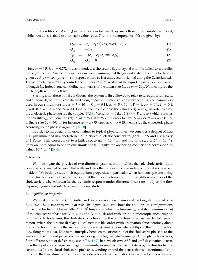
We first consider a CLC initialized in a quasi-two-dimensional rectangular box of sizeLy = 300× Lz = 100 with walls at rest. In Figure 1a,d, we show the equilibrium configurationsof the director field (obtained after t ' 105 time steps, when the free-energy is at its minimum value)of the cholesteric phase for N = 2 (a) and N = 4 (d) and with strong homeotropic anchoring onboth walls. In both cases, the cholesteric axis lies along the y-direction. One can clearly distinguishregions where the director displays a local nematic-like order (with orientation almost entirely alongthe z-direction, forced by the anchoring at the walls) from regions where it flips in the third direction(i.e., along the x-axis). Due to the interplay between the orientation of the cholesteric phase near thewalls and the imposed perpendicular anchoring, topological defects emerge. Although in cholesterics,four different types of defects may occur [36,41,42], here we observe λ±m and τ±m disclination defects(m is the topological charge, an integer or semi-integer number). While in λ defects, the director field iscontinuous (it is the local cholesteric pitch axis, winding around the defect, that is discontinuous) andflips into the third dimension at the λ line, τ defects are true disclinations as the director drops down at
Fluids 2018, 3, 47 7 of 14
the defect core. Note that in Figure 1a,d, those pinned at the walls are τ disclinations (of charge −1/2),which sustain a λ+1-charge region, where the director field flips into the third dimension. Changing thechirality also affects their position; indeed, when N = 4, τ disclinations appear closer to the boundaries,and λ-charge regions are longer and narrower than those observed when N = 2. It important tostress that, while it is easy to track numerically the location of τ disclination defects (for instance, bycomputing the local orientational order at each point), it is more difficult to resolve the correct positionof λ defects, as the radius of their core is usually comparable with the helix pitch p, and only a limitednumber of lattice points can be used to calculate its extension. This is why we prefer indicating regionscontaining λ defects (either of charge ±1 or couple of charge ±1/2) also as λ-charge regions.
The presence of an isotropic droplet in the center of the cell substantially modifies the equilibriumconfiguration of the cholesteric. In the absence (or for very weak values) of interface anchoring andwith N = 2 (Figure 1b), the droplet removes the λ-charge region and the two τ disclinations in thecenter of the box, leaving the rest of the cholesteric almost unaltered. If, on the other hand N = 4,the two τ disclinations in the center of the box survive (as they are closer to the walls), and the λ-chargeregion is simply covered by the droplet (Figure 1e). If strong homeotropic anchoring is imposed atthe droplet interface (Figure 1c–f), two fully in-plane topological defects of charge −1/2 emerge onopposite sides of the droplet and located along the equatorial line. Such strong anchoring importantlyalters the liquid crystal orientation in the surroundings of the droplet, favoring the formation of apronounced splay deformation.
A suitable quantity to measure the strength of the interface anchoring relative to the bulk elasticdeformation is the dimensionless number Λ = FintR/ΣK, where Fint =
∫V fintdV and Σ is the
perimeter of the droplet. For a droplet of size 1-10 µm, Λ usually ranges from 10−2–103. If Λ 1, theanchoring is weak, and no large deformations are observed in the surroundings of the droplet (as inFigure 1b–e, where Λ ' 0), whereas if Λ ∼ 1, the anchoring is considered strong, and large distortionsof the director with topological defects are found (see Figure 1c–f, where Λ ' 2.88).
(a) (d)
(b) (e)
(c) (f)
Figure 1. (a–d) Equilibrium configurations of the director field of a cholesteric liquid crystal in a cell ofsize Ly = 300 and Lz = 100 lattice units, for N = 2 (a) and N = 4 (d) π-twists of the helical axis. In bothcases, homeotropic anchoring is set at the walls. A λ+1-charge region is highlighted by a continuousline in (a). (b–f) Equilibrium configurations of an isotropic droplet surrounded by a cholesteric liquidcrystal. The radius of the droplet is R = 32 lattice units and the cholesteric pitch has N = 2 (b,c) andN = 4 (e,f) π-twists. While in (b,e) the interface anchoring is L = 0, in (c,f), L = −0.04 to enforcehomeotropic anchoring. The color map represents the largest eigenvalue of the Q tensor and rangesfrom zero (black) to '0.33 (yellow). τ disclinations are highlighted by blue-red spots as the scalar orderparameter drops down, while it is approximately constant in the rest of the cholesteric.
Fluids 2018, 3, 47 8 of 14
3.2. Cholesteric Liquid Crystal under Shear
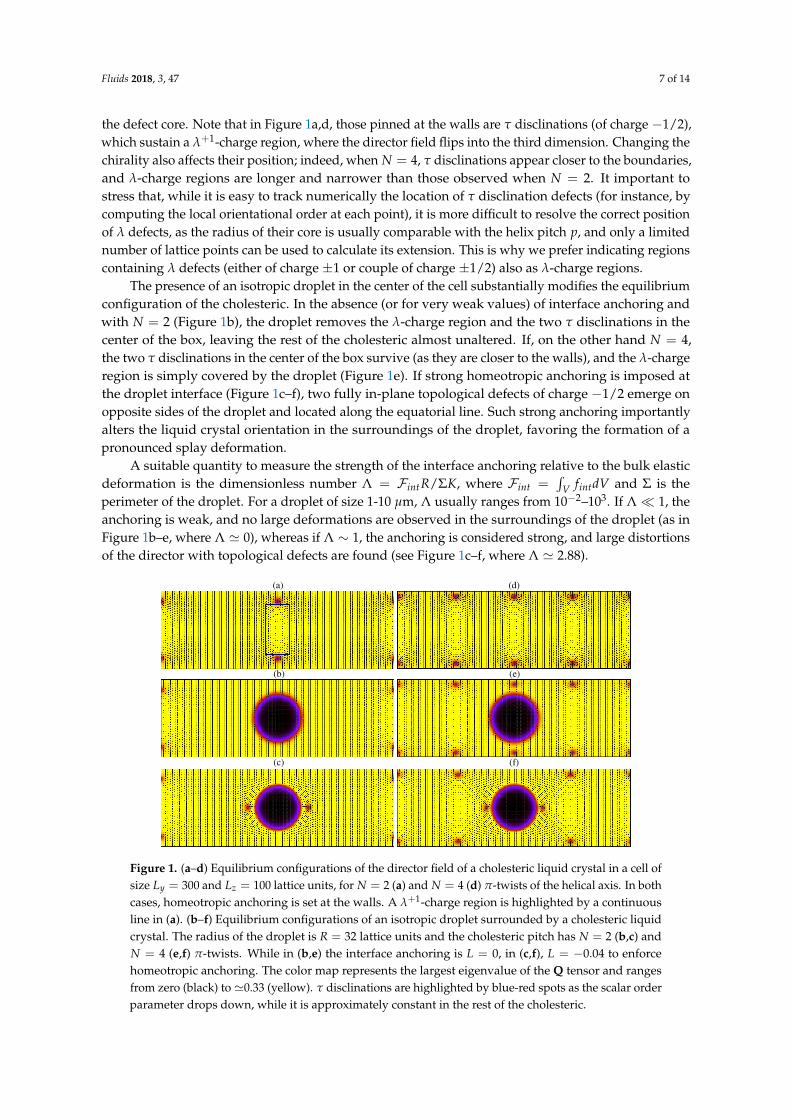
By starting from the equilibrated configurations previously described, we now study the rheologyof such systems when a symmetric shear flow is imposed. We move top and bottom walls alongthe y-axis with velocity uw (top) and −uw (bottom). This sets a shear rate γ = 2uw/Lz (measured in∆t−1 in simulation units) and a shear flow along the y-direction. We first consider the homogeneouscase in which no droplets are present. In Figure 2a–c, we show the steady state configurations of thedirector field for N = 2 and N = 4 and for a relatively weak shear rate (γ = 6× 10⁻⁵, i.e., uw = 0.003).With respect to the equilibrium state, the cholesteric layers are tilted along the direction imposedby the shear flow, while τ disclinations, still pinned at the walls, sustain S-shaped λ-charge regions.The primary flow uy (measured at y = Ly/2) is approximately Newtonian for N = 2, while itgets weakly sigmoidal N = 4 (Figure 2b), an effect due to the larger resistance to overcome elasticdeformations encountered by the flow when higher values of q0 are considered. Note that, as reportedin [25], a more flattened velocity profile (in which uy is zero almost everywhere along the z-direction)could be achieved if larger values of Lz and shorter values of Ly are considered. As expected, unlikethe case of a binary fluid mixture without liquid crystal (i.e., when Q = 0), a secondary flow ux
emerges due to the action of the director field on the velocity field along the x-direction (Figure 2d),stronger in the center of the sample (where it attains its larger value), but smaller than the primaryflow, and zero near the walls. Its negative sign is due to the handedness of the initial configuration ofthe liquid crystal. Note that the presence of a secondary flow is a signature of the permeation, i.e., asignificant increase in the viscosity (calculated as ηyz = σtotal
yz /∂zuy [25]) of the cholesteric liquid crystalobserved when it is subject to a flow in the direction of its helix (i.e., perpendicular to the directorfield) [1,23,25,43]. Our simulations show, for instance, that, if N = 4, ηyz attains a maximum at ∼ 0.65for γ = 6× 10⁻⁵ (in the center of the sample) and at ∼ 1.4 for γ = 8× 10⁻⁵. Such values are higherthan the isotropic viscosity η = 0.38.
(a)
(b)
(c)
(d)
Figure 2. (a–c) Steady-state configurations of the director field for N = 2 (a) and N = 4 (c) observedwhen a relatively weak symmetric shear flow (γ = 6× 10⁻⁵) is applied. (b–d) Profiles of the velocityfield uy (primary flow) and ux (secondary flow) taken at y = Ly/2 for a binary fluid (Q = 0) (red) anda cholesteric liquid crystal with N = 2 (green) and N = 4 (blue).
A well-established result of the rheology of liquid crystals is that if the shear rate is increased,the temperature at which the cholesteric-nematic transition occurs actually diminishes [18,25].While we confirm this result, we also find that the transition depends on the pitch length, namely N. In
Fluids 2018, 3, 47 9 of 14
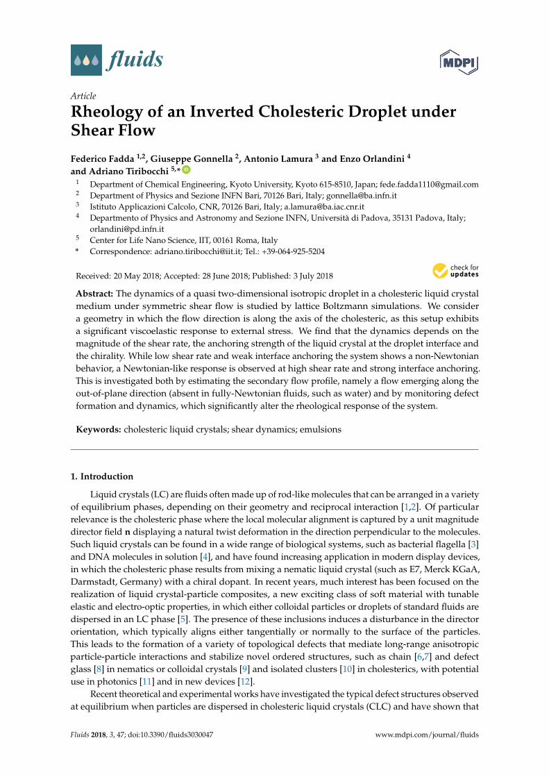
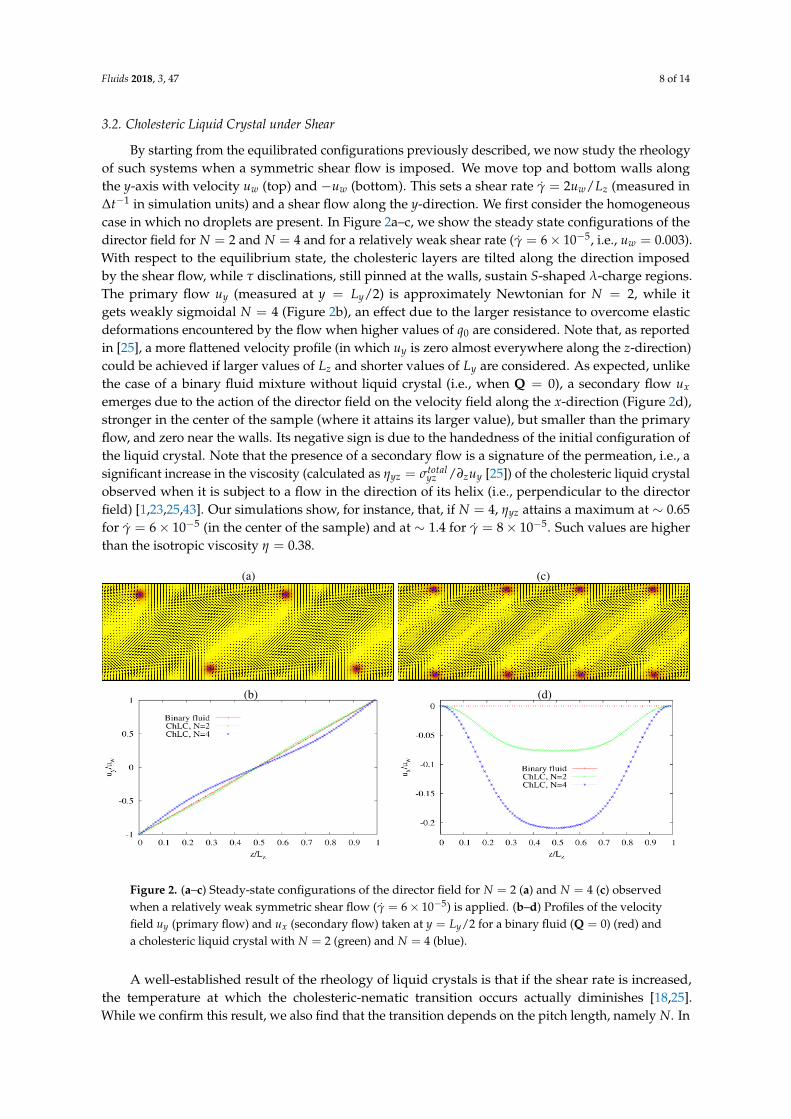
order to better appreciate it, in Figure 3, we show two dynamic configurations of the director field andof the corresponding velocity field for N = 4 and γ = 2× 10⁻⁴ (uw = 0.01), in a full three-dimensionalbox of size Lx = 5, Ly = 300, Lz = 100. While if N = 2 (and for the same shear rate), the cholestericis already in the nematic state (not shown), if N = 4, the system exhibits a more complex dynamics,in which double-twist cylinders (one of them is highlighted with a black dotted square in Figure 3a)periodically form and get destroyed by the fluid flow. Afterwards, the cholesteric arrangement istemporarily restored (Figure 3c) and disrupted again. The presence of double twist cylinders indicatesthat, within a range of values of the shear rate, the cholesteric-nematic transition is replaced by thecholesteric-blue phase, one for high values of N (namely for a higher chirality). Interestingly, duringthe blue-phase-like regime, topological defects at the walls acquire a positive charge (they are nowactually τ1/2 disclinations, indicated by red cylinders in Figure 3a), while the topological charge of theλ region (highlighted by a green circle in Figure 3a) switches to −1. The velocity field shows largevortices in the surroundings of such defects (Figure 3b), while far from them, it has the typical structureof sheared systems (such as in Figure 3d), i.e., a bidirectional flow, strong near the walls and muchweaker in the middle of the cell.
(a) (c)
(b) (d)
z
yx
yx
z
Figure 3. (a–c) Dynamic configurations of the director field observed when a symmetric shear rateγ = 2× 10⁻⁴ is applied to a cholesteric sample with N = 4 in a 3D system of size Lx = 5, Ly = 300 andLz = 100. Here, ta < tc, where ta and tc indicate the simulation times of (a,c), respectively. Red columnsindicate regions where the scalar order parameter drops down and where τ1/2 disclinations form.The green circle indicates a λ−1-charge region, whereas the black dotted square a double twist cylinder.In (b,d) the velocity fields corresponding to panels (a,c), respectively, are shown. The color of thearrows ranges from u = 0.01 (at the walls) to u ' 10−5 in the middle of the cell.
3.3. Isotropic Droplet in the Cholesteric Phase under Shear
We now describe the rheological properties of a system in which an isotropic droplet is includedin the cholesteric phase. We consider low/moderate values of shear rate, comparable to those used forthe cholesteric cell without droplet. This also ensures that the system remains firmly in the cholestericphase, and finite size effects due to periodic boundary conditions and artificial interactions betweendroplet mirror images should also be minimized. Two dimensionless numbers useful to quantify theeffects of the shear flow on the droplet are the capillary number Ca and the deformation parameter D.The former is defined as Ca = RγηΣ
FKb f(where FKb f =
∫V dV(Kb f /2)|∇φ|2) and measures the strength of
viscous forces relative to the surface tension mediated by the constant Kb f , while the latter is defined
Fluids 2018, 3, 47 10 of 14
as D = a−ba+b [44] (where a and b are the major and the minor axis of an elliptical droplet) and quantifies
the droplet deformation under shear. If low or moderate shear flows are considered, Ca is expected tobe ∼0.01, while D between zero (no deformation) and 0.1 (weak/moderate deformation).
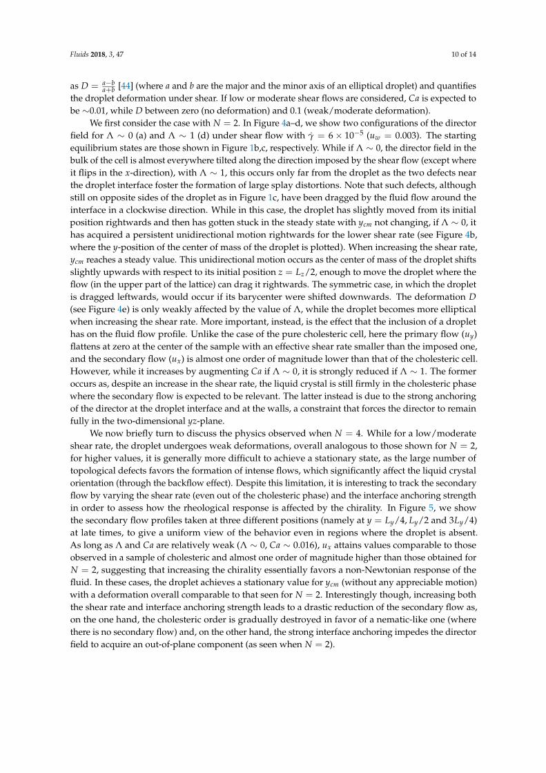
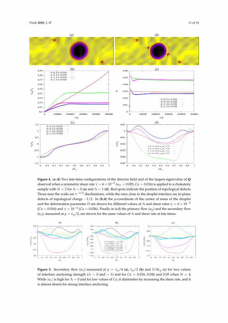
We first consider the case with N = 2. In Figure 4a–d, we show two configurations of the directorfield for Λ ∼ 0 (a) and Λ ∼ 1 (d) under shear flow with γ = 6× 10⁻⁵ (uw = 0.003). The startingequilibrium states are those shown in Figure 1b,c, respectively. While if Λ ∼ 0, the director field in thebulk of the cell is almost everywhere tilted along the direction imposed by the shear flow (except whereit flips in the x-direction), with Λ ∼ 1, this occurs only far from the droplet as the two defects nearthe droplet interface foster the formation of large splay distortions. Note that such defects, althoughstill on opposite sides of the droplet as in Figure 1c, have been dragged by the fluid flow around theinterface in a clockwise direction. While in this case, the droplet has slightly moved from its initialposition rightwards and then has gotten stuck in the steady state with ycm not changing, if Λ ∼ 0, ithas acquired a persistent unidirectional motion rightwards for the lower shear rate (see Figure 4b,where the y-position of the center of mass of the droplet is plotted). When increasing the shear rate,ycm reaches a steady value. This unidirectional motion occurs as the center of mass of the droplet shiftsslightly upwards with respect to its initial position z = Lz/2, enough to move the droplet where theflow (in the upper part of the lattice) can drag it rightwards. The symmetric case, in which the dropletis dragged leftwards, would occur if its barycenter were shifted downwards. The deformation D(see Figure 4e) is only weakly affected by the value of Λ, while the droplet becomes more ellipticalwhen increasing the shear rate. More important, instead, is the effect that the inclusion of a droplethas on the fluid flow profile. Unlike the case of the pure cholesteric cell, here the primary flow (uy)flattens at zero at the center of the sample with an effective shear rate smaller than the imposed one,and the secondary flow (ux) is almost one order of magnitude lower than that of the cholesteric cell.However, while it increases by augmenting Ca if Λ ∼ 0, it is strongly reduced if Λ ∼ 1. The formeroccurs as, despite an increase in the shear rate, the liquid crystal is still firmly in the cholesteric phasewhere the secondary flow is expected to be relevant. The latter instead is due to the strong anchoringof the director at the droplet interface and at the walls, a constraint that forces the director to remainfully in the two-dimensional yz-plane.
We now briefly turn to discuss the physics observed when N = 4. While for a low/moderateshear rate, the droplet undergoes weak deformations, overall analogous to those shown for N = 2,for higher values, it is generally more difficult to achieve a stationary state, as the large number oftopological defects favors the formation of intense flows, which significantly affect the liquid crystalorientation (through the backflow effect). Despite this limitation, it is interesting to track the secondaryflow by varying the shear rate (even out of the cholesteric phase) and the interface anchoring strengthin order to assess how the rheological response is affected by the chirality. In Figure 5, we showthe secondary flow profiles taken at three different positions (namely at y = Ly/4, Ly/2 and 3Ly/4)at late times, to give a uniform view of the behavior even in regions where the droplet is absent.As long as Λ and Ca are relatively weak (Λ ∼ 0, Ca ∼ 0.016), ux attains values comparable to thoseobserved in a sample of cholesteric and almost one order of magnitude higher than those obtained forN = 2, suggesting that increasing the chirality essentially favors a non-Newtonian response of thefluid. In these cases, the droplet achieves a stationary value for ycm (without any appreciable motion)with a deformation overall comparable to that seen for N = 2. Interestingly though, increasing boththe shear rate and interface anchoring strength leads to a drastic reduction of the secondary flow as,on the one hand, the cholesteric order is gradually destroyed in favor of a nematic-like one (wherethere is no secondary flow) and, on the other hand, the strong interface anchoring impedes the directorfield to acquire an out-of-plane component (as seen when N = 2).
Fluids 2018, 3, 47 11 of 14
(a)
(b)
(c)
(d)
(e)
(f)
Figure 4. (a–d) Two late-time configurations of the director field and of the largest eigenvalue of Qobserved when a symmetric shear rate γ = 6× 10⁻⁵ (uw = 0.003, Ca ∼ 0.016) is applied to a cholestericsample with N = 2 for Λ ∼ 0 (a) and Λ ∼ 1 (d). Red spots indicate the position of topological defects.Those near the walls are τ−1/2 disclinations, while the ones close to the droplet interface are in-planedefects of topological charge −1/2. In (b,d) the y-coordinate of the center of mass of the dropletand the deformation parameter D are shown for different values of Λ and shear rates γ = 6× 10⁻⁵
(Ca ∼ 0.016) and γ = 10−4 (Ca ∼ 0.026). Finally in (c,f) the primary flow (uy) and the secondary flow(ux), measured at y = Ly/2, are shown for the same values of Λ and shear rate at late times.
(a) (b) (c)
Figure 5. Secondary flow (ux) measured at y = Ly/4 (a), Ly/2 (b) and 3/4Ly (c) for two valuesof interface anchoring strength (Λ ∼ 0 and ∼ 1) and for Ca = 0.016, 0.026 and 0.05 when N = 4.While |ux| is high for Λ ∼ 0 and for low values of Ca, it diminishes by increasing the shear rate, and itis almost absent for strong interface anchoring.
Fluids 2018, 3, 47 12 of 14
4. Conclusions
To summarize, we have studied, by numerical simulations, the rheological response of an invertedcholesteric droplet sandwiched between two planar walls under a symmetric shear flow. We haveshown that the dynamics is affected by the shear rate, the strength of the interface anchoring andthe chirality of the cholesteric. In particular, the presence of a relatively intense secondary flow(emerging out of the plane of the cholesteric) suggests that the system is essentially non-Newtonian,an effect generally weakened if an isotropic droplet is included and further reduced if strong interfaceanchoring is imposed.
If the droplet is absent, a moderate shear flow drives the sample towards a steady state inwhich the director field is almost everywhere tilted along the direction imposed by the shear itself,except in regions where the S-like λ-charge region is sustained by τ disclinations pinned at the walls.Importantly, increasing the chirality favors a non-Newtonian response of the cholesteric witnessed bya sustained secondary flow. On the other hand, augmenting the shear-rate determines a decrease of thetransition temperature, which leads the system to either the nematic state or, if the chirality is higher,to a blue-phase-like state. The dynamics is significantly different if an isotropic droplet is embedded inthe sample. If the interface anchoring is weak, we generally find a reduction of the secondary flowwith respect to the droplet-free cholesteric sample, an effect even more pronounced if the interfaceanchoring is strong. We ascribe the latter effect to the resistance encountered by the flow to overcome alarger elastic deformation of the director field, in particular near the droplet interface where two fullyin-plane topological defects form. These results are overall confirmed when the chirality is increased,although here an intense secondary flow, comparable to that observed in the droplet-free sample,is found for the low shear-rate and weak anchoring. This highlights the fact that the rheologicalresponse displayed by an inverted cholesteric droplet has a complex landscape where a key role isplayed by at least three quantities: shear rate, elasticity and chirality.
Our results represent a first step in the study of the rheology of an inverted cholesteric dropletand is of possible interest for designing CLC-based devices built from an emulsion. This opens upseveral directions for future research. It would be worth investigating the case in which tangentialanchoring is considered (both at the droplet interface and at the walls) in a cholesteric sample whoseaxis is perpendicular to the walls. Besides yielding to the formation of different topological defects(such as a twisted Saturn ring in 3D), such a configuration is expected to display a rich dynamicalbehavior like that observed with homeotropic interface anchoring, which strongly depend on thecholesteric pitch (or the chirality). This can pave the way to extend the study to include severaldroplets, either in a monodisperse setup or in the more intriguing polydisperse one where differentdroplet interface anchoring sets may be considered. One can envisage, for instance, the design of anew soft material made of highly-packed isotropic droplets, the resistance to deformation of whichcould be sustained by the liquid crystal dispersed in between. Finally, although three-dimensionalsimulations can be computationally demanding, it would be surely of great interest to investigate thephysics of more realistic systems in order, for instance, to minimize finite size effects. However, wenote that quasi-two-dimensional liquid crystal devices could be experimentally realized, such as thatdescribed in [45], where a smectic-C film surrounding droplets, obtained by nucleation, is proposed.
Author Contributions: F.F., G.G., A.L., E.O. and A.T. designed and performed the research and wrotethe manuscript.
Acknowledgments: This research received no external funding.
Conflicts of Interest: The authors declare no conflict of interest.
References
1. de Gennes, P.G.; Prost, J. The Physics of Liquid Crystals; Clarendon Press Oxford: Oxford, UK, 1993.2. Chandrasekhar, S. Liquid Crystals; Cambridge University Press: Cambridge, UK, 1977.
Fluids 2018, 3, 47 13 of 14
3. Berg, H.C.; Anderson, R.A. Bacteria swim by rotating their flagellar filaments. Nature 1973, 245, 380–382.[CrossRef] [PubMed]
4. Watson, J.D.; Crick, F.H.C. Molecular structure of nucleic acids: A structure for deoxyribose nucleic acid.Nature 1953, 171, 737–738. [CrossRef] [PubMed]
5. Musevic, I.; Skarabot, M.; Humar, M. Direct and inverted nematic dispersions for soft matter photonics.J. Phys. Condens. Matter 2011, 23, 284112. [CrossRef] [PubMed]
6. Loudet, J.C.; Barois, P.; Poulin, P. Colloidal ordering from phase separation in a liquid-crystalline continuousphase. Nature 2000 407, 611–613. [PubMed]
7. Poulin, P.; Stark, H.; Lubensky, T.C.; Weitz, D.A. Novel colloidal interactions in anisotropic fluids. Science1997, 275, 1770–1773. [CrossRef] [PubMed]
8. Wood, T.A.; Lintuvuori, J.S.; Schofield, A.B.; Marenduzzo, D.; Poon, W.C.K. A self-quenched defect glass in acolloid-nematic liquid crystal composite. Science 2011, 334, 79–83. [CrossRef] [PubMed]
9. Ravnik, M.; Alexander, G.P.; Yoemans, J.M.; Zumer, S. Three-dimensional colloidal crystals in liquid crystallineblue phases. Proc. Natl. Acad. Sci. USA 2011, 108, 5188–5192. [CrossRef] [PubMed]
10. Stratford, K.; Henrich, O.; Lintuvuori, J.S.; Cates, M.E.; Marenduzzo, D. Self-assembly of colloid-cholestericcomposites provides a possible route to switchable optical materials. Nat. Commun. 2014, 5, 3954. [CrossRef][PubMed]
11. Smalyukh, I.I.; Lansac, I.; Clark, N.A.; Trivedi, R.P. Three-dimensional structure and multistable opticalswitching of triple-twisted particle-like excitations in anisotropic fluids. Nat. Mater. 2010, 9, 139–145.[CrossRef] [PubMed]
12. Chari, K.; Rankin, C.M.; Johnson, D.M.; Blanton, T.N.; Capurso, R.G. Single-substrate cholesteric liquid crystaldisplays by colloidal self-assembly. Appl. Phys. Lett. 2006, 88, 043502. [CrossRef]
13. Lintuvuori, J.S.; Stratford, K.; Cates, M.E.; Marenduzzo, D. Colloids in cholesterics: Size-dependent defectsand non-Stokesian microrheology. Phys. Rev. Lett. 2010, 105, 178302. [CrossRef] [PubMed]
14. Lintuvuori, J.S.; Marenduzzo, D.; Stratford, K.; Cates, M.E. Colloids in liquid crystals: A lattice Boltzmannstudy. J. Mater. Chem. 2010, 20, 10547–10552. [CrossRef]
15. Foffano, G.; Lintuvuori, J.S.; Tiribocchi, A.; Marenduzzo, D. The dynamics of colloidal intrusions in liquidcrystals: A simulation perspective. Liq. Crys. Rev. 2014, 2, 1–27. [CrossRef]
16. Jampani, V.S.R.; Skarabot, M.; Ravnik, M.; Copar, S.; Zumer, S.; Musevic, I. Colloidal entanglement in highlytwisted chiral nematic colloids: Twisted loops, hopf links, and trefoil knots. Phys. Rev. E. 2011, 84, 031703.[CrossRef] [PubMed]
17. Tiribocchi, A.; Da Re, M.; Marenduzzo, D.; Orlandini, E. Shear dynamics of an inverted nematic emulsion.Soft Matter 2016, 12, 8195–8213. [CrossRef] [PubMed]
18. Olmsted, P.D.; Goldbart, P.M. Isotropic-nematic transition in shear flow: State selection, coexistence,phase transitions, and critical behavior. Phys. Rev. A 1992, 46, 4966–4993. [CrossRef] [PubMed]
19. Olmsted, P.D.; David Lu, C.-Y. Phase separation of rigid-rod suspensions in shear flow. Phys. Rev. E 1999,60, 4397–4415. [CrossRef]
20. Marenduzzo, D.; Orlandini E.; Yeomans, J.M. Rheology of distorted nematic liquid crystals. EuroPhys. Lett.2003, 64, 406–412. [CrossRef]
21. Tsuji, T.; Rey, A. Orientation mode selection mechanisms for sheared nematic liquid crystalline materials.Phys. Rev. E 1998, 57, 5609–5625. [CrossRef]
22. Tsuji, T.; Rey, A. Effect of long range order on sheared liquid crystalline materials Part 1: Compatibility betweentumbling behavior and fixed anchoring. J. Non-Newtonian Fluid. Mech. 1997, 73, 127–152. [CrossRef]
23. Helfrich, W. Capillary flow of cholesteric and smectic liquid crystals. Phys. Rev. Lett. 1969, 23, 372–374.[CrossRef]
24. Hongladarom, K.; Secakusuma, V.; Burghardt, W.R. Relation between molecular orientation and rheology inlyotropic hydroxypropylcellulose solutions. J. Rheol. 1994, 38, 1505–1523. [CrossRef]
25. Marenduzzo, D.; Orlandini, E.; Yeomans, J.M.; Permeative flows in cholesterics: Shear and Poiseuille flows.J. Chem. Phys. 2006, 124, 204906. [CrossRef] [PubMed]
26. Lintuvuori, J.S.; Stratford, K.; Cates, M.E.; Marenduzzo, D. Self-assembly and nonlinear dynamics of dimericcolloidal rotors in cholesterics. Phys. Rev. Lett. 2011, 107, 267802. [CrossRef] [PubMed]
27. Succi, S. The Lattice Boltzmann Equation: For Complex States of Flowing Matter; Oxford University Press: Oxford,UK, 2018.
Fluids 2018, 3, 47 14 of 14
28. Beris, A.; Edwards, B. Thermodynamics of Flowing Systems; Oxford Science Publications: Oxford, UK, 1994.29. Sulaiman, N.; Marenduzzo, D.; Yeomans, J.M. Lattice Boltzmann algorithm to simulate isotropic-nematic
emulsions. Phys. Rev. E 2006, 74, 041708. [CrossRef] [PubMed]30. Wright, D.C.; Mermin, N.D. Crystalline liquids: The blue phases. Rev. Mod. Phys. 1989, 61, 385–425. [CrossRef]31. Poulin, P.; Weitz, D.A. Inverted and multiple nematic emulsions. Phys. Rev. E 1998, 57, 626–637. [CrossRef]32. Cates, M.E.; Henrich, O.; Marenduzzo, D.; Stratford, K. Lattice Boltzmann simulations of liquid crystalline
fluids: Active gels and blue phases. Soft Matter 2009, 5, 3791–3800. [CrossRef]33. Tiribocchi, A.; Gonnella, G.; Marenduzzo, D.; Orlandini, E. Switching dynamics in cholesteric blue phases.
Soft Matter 2011, 7, 3295–3306. [CrossRef]34. Tiribocchi, A.; Gonnella, G.; Marenduzzo, D.; Orlandini, E.; Salvafore, F. Bistable defect structures in blue
phase devices. Phys. Rev. Lett. 2011, 107, 237803. [CrossRef] [PubMed]35. Tiribocchi, A.; Cates, M.E.; Gonnella, G.; Marenduzzo, D.; Orlandini, E. Flexoelectric switching in cholesteric
blue phases. Soft Matter 2013, 9, 4831–4842. [CrossRef]36. Fadda, F.; Gonnella, G.; Marenduzzo, D.; Orlandini, E.; Tiribocchi, A. Switching dynamics in cholesteric liquid
crystal emulsions. J. Chem. Phys. 2017, 147, 064903. [CrossRef] [PubMed]37. Dupuis, A.; Marenduzzo, D.; Yeomans, J.M. Numerical calculations of the phase diagram of cubic blue phases
in cholesteric liquid crystals. Phys. Rev. E 2005 71, 011703. [CrossRef] [PubMed]38. Henrich, O.; Marenduzzo, D.; Stratford, K.; Cates, M.E. Thermodynamics of blue phases in electric fields.
Phys. Rev. E 2010, 81, 031706. [CrossRef] [PubMed]39. Henrich, O.; Marenduzzo, D.; Stratford, K.; Cates, M.E. Domain growth in cholesteric blue phases: Hybrid
lattice Boltzmann simulations. Comput. Math. Appl. 2010, 49, 2360–2369 [CrossRef]40. Anderson, V.J.; Terentjev, E.M.; Meeker, S.P.; Crain, J.; Poon, W.C.K. Cellular solid behaviour of liquid crystal
colloids 1. Phase separation and morphology. Eur. Phys. J. E 2001, 4, 11–20. [CrossRef]41. Kleman, M. Lavrentovich, O. Soft Matter Physics: An Introduction; Springer: Berlin, Germany, 2001.42. Kleman, M. Points, Lines and Walls; John Wiley & Sons: Hoboken, NJ, USA, 1983.43. Lubensky, T.C. Hydrodynamics of Cholesteric Liquid Crystals. Phys. Rev. A 1972, 6, 452–470. [CrossRef]44. Taylor, G.I.; The formation of emulsions in definable fields of flow. Proc. R. Soc. Lond. Ser. A 1934, 146, 501–523.
[CrossRef]45. Cluzeau, P.; Bonnand, V.; Joly, G.; Dolganov, V.; Nguyen, H.T. Self-organization of N∗ inclusions in SmC∗
free-standing films. Eur. Phys. J. E 2003, 10, 231–240. [CrossRef] [PubMed]
© 2018 by the authors. Licensee MDPI, Basel, Switzerland. This article is an open accessarticle distributed under the terms and conditions of the Creative Commons Attribution(CC BY) license (http://creativecommons.org/licenses/by/4.0/).