Embed Size (px)
Citation preview
THIS MODEL
17.010.0
USES LESS ENERGY
Seasonal Energy Efficiency Ratio - SEER
17.00
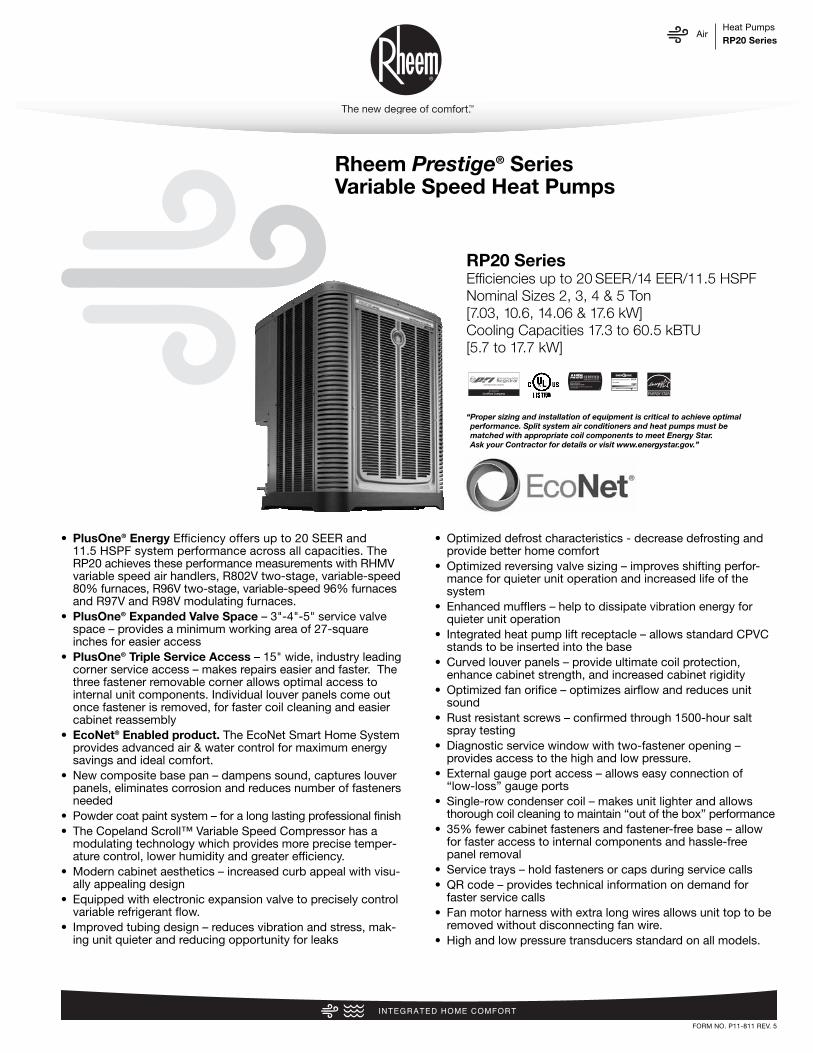
Rheem Prestige® SeriesVariable Speed Heat Pumps
FORM NO. P11-811 REV. 5
AirHeat PumpsRP20 Series
“Proper sizing and installation of equipment is critical to achieve optimalperformance. Split system air conditioners and heat pumps must bematched with appropriate coil components to meet Energy Star. Ask your Contractor for details or visit www.energystar.gov.”
RP20 SeriesEfficiencies up to 20 SEER/14 EER/11.5 HSPFNominal Sizes 2, 3, 4 & 5 Ton [7.03, 10.6, 14.06 & 17.6 kW]Cooling Capacities 17.3 to 60.5 kBTU[5.7 to 17.7 kW]
• PlusOne® Energy Efficiency offers up to 20 SEER and 11.5 HSPF system performance across all capacities. TheRP20 achieves these performance measurements with RHMVvariable speed air handlers, R802V two-stage, variable-speed80% furnaces, R96V two-stage, variable-speed 96% furnaces and R97V and R98V modulating furnaces.
• PlusOne® Expanded Valve Space – 3"-4"-5" service valvespace – provides a minimum working area of 27-squareinches for easier access
• PlusOne® Triple Service Access – 15" wide, industry leadingcorner service access – makes repairs easier and faster. Thethree fastener removable corner allows optimal access tointernal unit components. Individual louver panels come outonce fastener is removed, for faster coil cleaning and easiercabinet reassembly
• EcoNet® Enabled product. The EcoNet Smart Home Systemprovides advanced air & water control for maximum energysavings and ideal comfort.
• New composite base pan – dampens sound, captures louverpanels, eliminates corrosion and reduces number of fastenersneeded
• Powder coat paint system – for a long lasting professional finish• The Copeland Scroll™ Variable Speed Compressor has a
modulating technology which provides more precise temper-ature control, lower humidity and greater efficiency.
• Modern cabinet aesthetics – increased curb appeal with visu-ally appealing design
• Equipped with electronic expansion valve to precisely controlvariable refrigerant flow.
• Improved tubing design – reduces vibration and stress, mak-ing unit quieter and reducing opportunity for leaks
• Optimized defrost characteristics - decrease defrosting andprovide better home comfort
• Optimized reversing valve sizing – improves shifting perfor-mance for quieter unit operation and increased life of thesystem
• Enhanced mufflers – help to dissipate vibration energy forquieter unit operation
• Integrated heat pump lift receptacle – allows standard CPVCstands to be inserted into the base
• Curved louver panels – provide ultimate coil protection,enhance cabinet strength, and increased cabinet rigidity
• Optimized fan orifice – optimizes airflow and reduces unitsound
• Rust resistant screws – confirmed through 1500-hour saltspray testing
• Diagnostic service window with two-fastener opening – provides access to the high and low pressure.
• External gauge port access – allows easy connection of“low-loss” gauge ports
• Single-row condenser coil – makes unit lighter and allowsthorough coil cleaning to maintain “out of the box” performance
• 35% fewer cabinet fasteners and fastener-free base – allowfor faster access to internal components and hassle-freepanel removal
• Service trays – hold fasteners or caps during service calls• QR code – provides technical information on demand for
faster service calls• Fan motor harness with extra long wires allows unit top to be
removed without disconnecting fan wire.• High and low pressure transducers standard on all models.

AirTable of ContentsRP20 Series
2
TABLE OF CONTENTSStandard Feature ......................................................................................................3
Available SKUs ........................................................................................................3
Features & Benefits ..............................................................................................4-8
Model Number Identification ..............................................................................9-10
General Data/Electrical Data ..................................................................................11
Accessories ..........................................................................................................12
Weighted Sound Power ..........................................................................................12
Smart Home Systems ............................................................................................13
Unit Dimensions......................................................................................................14
Clearances..............................................................................................................15
Refrigerant Line Size Information ......................................................................16-17
Capacity Ranges ..............................................................................................18-21
Performance Data ............................................................................................22-24
Guide Specifications ..............................................................................................25
Limited Warranty ....................................................................................................26
AirStandard Feature/Available SKUsRP20 Series
3
STANDARD FEATURES
Feature 24 36 48 60
R-410A Refrigerant √ √ √ √Maximum SEER 20 20 19.5 19.5Maximum EER 14 14 12.5 11.5Maximum HSPF 11 11.5 11 11EcoNet Enabled √ √ √ √Copeland Scroll™ Variable Speed Compressor √ √ √ √Compressor Sound Blanket √ √ √ √Variable speed outdoor fan motor √ √ √ √Swept wing fan blade √ √ √ √Field Installed Filter Drier √ √ √ √Front Seating Service Valves √ √ √ √Internal Pressure Relief Valve √ √ √ √Internal Thermal Overload √ √ √ √Low Ambient capability √ √ √ √3-4-5 Expanded Valve Space √ √ √ √Composite Basepan √ √ √ √1" Screw Control Box Access √ √ √ √15" Access to Internal Components √ √ √ √Quick release louver panel design √ √ √ √No fasteners to remove along bottom √ √ √ √Optimized Venturi Airflow √ √ √ √Single row condenser coil √ √ √ √Powder coated paint √ √ √ √Rust resistant screws √ √ √ √QR code √ √ √ √External gauge ports √ √ √ √Service trays √ √ √ √
√ = Standard
Standard Feature Table
Available SKUsAvailable Models Description
RP2024BJVCA 2 ton EcoNet® Enabled Inverter Driven Rheem Prestige ® Series Variable Speed Heat Pump-208/230/1/60
RP2036BJVCA 3 ton EcoNet® Enabled Inverter Driven Rheem Prestige ® Series Variable Speed Heat Pump-208/230/1/60
RP2048BJVCA 4 ton EcoNet® Enabled Inverter Driven Rheem Prestige ® Series Variable Speed Heat Pump-208/230/1/60
RP2060BJVCA 5 ton EcoNet® Enabled Inverter Driven Rheem Prestige ® Series Variable Speed Heat Pump-208/230/1/60
AirFeatures & BenefitsRP20 Series
4
Introduction to RP20 Heat Pump
The RP20 is our EcoNet® Enabled, Inverter Driven Prestige®
Series Variable Speed Heat Pump and is part of the Rheem HeatPump product line that extends from 13 to 20 SEER. This highlyfeatured and reliable heat pump is designed for years ofdependable, efficient operation when matched with Rheemindoor aluminum evaporator coils and furnaces or air handlers.
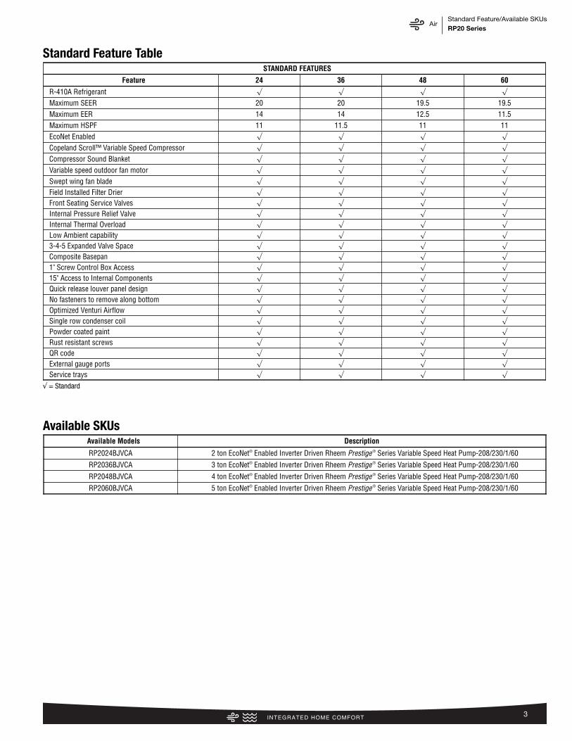
The Prestige® Series RP20 is part of a new line of Rheem smartheating, cooling and water heating products. Using the latest insensor technology and a powerful EcoNet® monitoring system,Rheem provides homeowners with a new level of protection, con-trol and energy savings. Rheem smart heating, cooling and waterheating products will alert the homeowner if there is ever an issuevia the EcoNet Smart Thermostat ( ) and the EcoNet Mobileapp. The EcoNet Mobile App makes it easy for homeowners tomanage their home comfort environment at home or on-the-go*,while enjoying the convenience and savings benefits of a highlyefficient system.
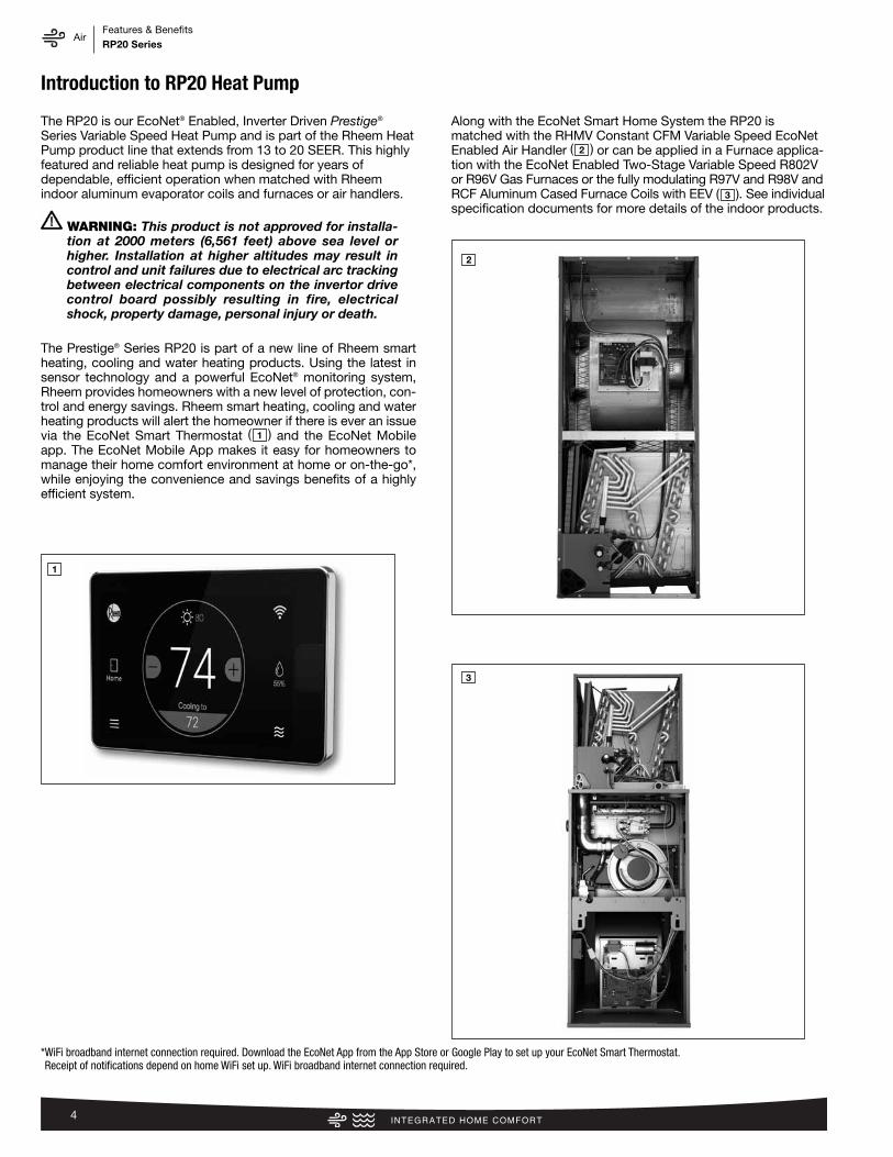
Along with the EcoNet Smart Home System the RP20 ismatched with the RHMV Constant CFM Variable Speed EcoNetEnabled Air Handler ( ) or can be applied in a Furnace applica-tion with the EcoNet Enabled Two-Stage Variable Speed R802Vor R96V Gas Furnaces or the fully modulating R97V and R98V andRCF Aluminum Cased Furnace Coils with EEV ( ). See individualspecification documents for more details of the indoor products.
2
3
1
1
2
3
*WiFi broadband internet connection required. Download the EcoNet App from the App Store or Google Play to set up your EcoNet Smart Thermostat. Receipt of notifications depend on home WiFi set up. WiFi broadband internet connection required.
WARNING: This product is not approved for installa-tion at 2000 meters (6,561 feet) above sea level orhigher. Installation at higher altitudes may result incontrol and unit failures due to electrical arc trackingbetween electrical components on the invertor drivecontrol board possibly resulting in fire, electricalshock, property damage, personal injury or death.
AirFeatures & BenefitsRP20 Series
5
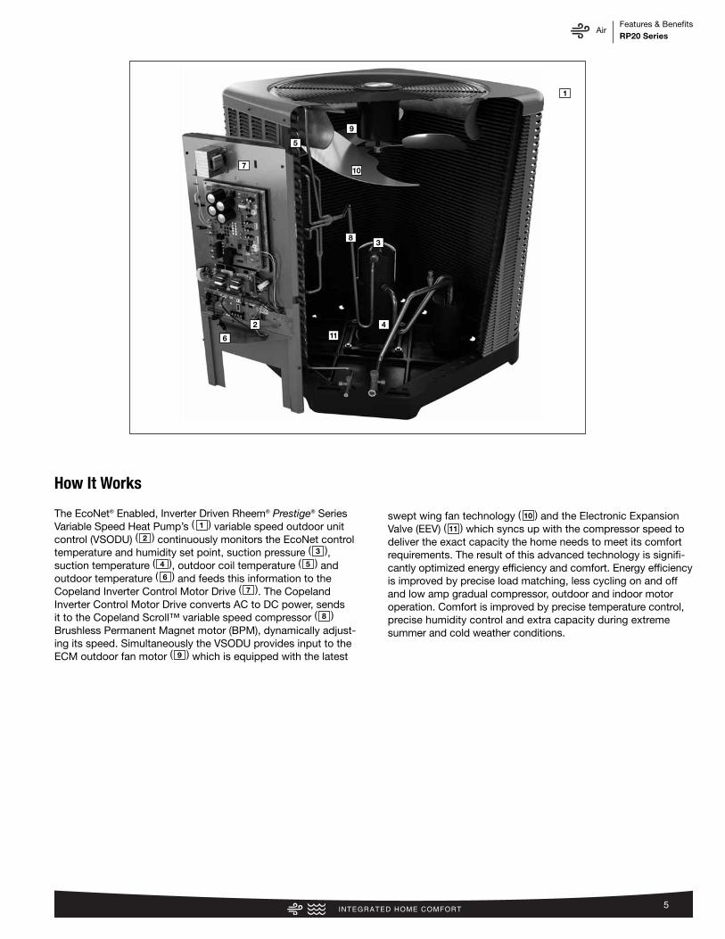
The EcoNet® Enabled, Inverter Driven Rheem® Prestige® SeriesVariable Speed Heat Pump’s ( ) variable speed outdoor unitcontrol (VSODU) ( ) continuously monitors the EcoNet controltemperature and humidity set point, suction pressure ( ), suction temperature ( ), outdoor coil temperature ( ) andoutdoor temperature ( ) and feeds this information to theCopeland Inverter Control Motor Drive ( ). The CopelandInverter Control Motor Drive converts AC to DC power, sendsit to the Copeland Scroll™ variable speed compressor ( )Brushless Permanent Magnet motor (BPM), dynamically adjust-ing its speed. Simultaneously the VSODU provides input to theECM outdoor fan motor ( ) which is equipped with the latest
swept wing fan technology ( ) and the Electronic ExpansionValve (EEV) ( ) which syncs up with the compressor speed todeliver the exact capacity the home needs to meet its comfortrequirements. The result of this advanced technology is signifi-cantly optimized energy efficiency and comfort. Energy efficiencyis improved by precise load matching, less cycling on and offand low amp gradual compressor, outdoor and indoor motoroperation. Comfort is improved by precise temperature control,precise humidity control and extra capacity during extreme summer and cold weather conditions.
1
2
3
4 5
6
7
8
9
10
11
How It Works
9
5
7
6
211
4
38
10
1
AirFeatures & BenefitsRP20 Series
6
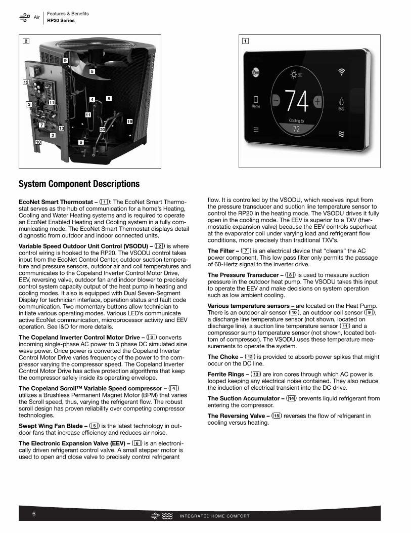
EcoNet Smart Thermostat – ( ): The EcoNet Smart Thermo-stat serves as the hub of communication for a home’s Heating,Cooling and Water Heating systems and is required to operatean EcoNet Enabled Heating and Cooling system in a fully com-municating mode. The EcoNet Smart Thermostat displays detaildiagnostic from outdoor and indoor connected units.
Variable Speed Outdoor Unit Control (VSODU) – ( ) is wherecontrol wiring is hooked to the RP20. The VSODU control takesinput from the EcoNet Control Center, outdoor suction tempera-ture and pressure sensors, outdoor air and coil temperatures andcommunicates to the Copeland Inverter Control Motor Drive,EEV, reversing valve, outdoor fan and indoor blower to preciselycontrol system capacity output of the heat pump in heating andcooling modes. It also is equipped with Dual Seven-SegmentDisplay for technician interface, operation status and fault codecommunication. Two momentary buttons allow technician toinitiate various operating modes. Various LED’s communicateactive EcoNet communication, microprocessor activity and EEVoperation. See I&O for more details.
The Copeland Inverter Control Motor Drive – ( ) convertsincoming single-phase AC power to 3 phase DC simulated sinewave power. Once power is converted the Copeland InverterControl Motor Drive varies frequency of the power to the com-pressor varying the compressor speed. The Copeland InverterControl Motor Drive has active protection algorithms that keepthe compressor safely inside its operating envelope.
The Copeland Scroll™ Variable Speed compressor – ( )utilizes a Brushless Permanent Magnet Motor (BPM) that variesthe Scroll speed, thus, varying the refrigerant flow. The robustscroll design has proven reliability over competing compressortechnologies.
Swept Wing Fan Blade – ( ) is the latest technology in out-door fans that increase efficiency and reduces air noise.
The Electronic Expansion Valve (EEV) – ( ) is an electroni-cally driven refrigerant control valve. A small stepper motor isused to open and close valve to precisely control refrigerant
flow. It is controlled by the VSODU, which receives input fromthe pressure transducer and suction line temperature sensor tocontrol the RP20 in the heating mode. The VSODU drives it fullyopen in the cooling mode. The EEV is superior to a TXV (ther-mostatic expansion valve) because the EEV controls superheatat the evaporator coil under varying load and refrigerant flowconditions, more precisely than traditional TXV’s.
The Filter – ( ) is an electrical device that “cleans” the ACpower component. This low pass filter only permits the passageof 60-Hertz signal to the inverter drive.
The Pressure Transducer – ( ) is used to measure suctionpressure in the outdoor heat pump. The VSODU takes this inputto operate the EEV and make decisions on system operationsuch as low ambient cooling.
Various temperature sensors – are located on the Heat Pump.There is an outdoor air sensor ( ), an outdoor coil sensor ( ),a discharge line temperature sensor (not shown, located ondischarge line), a suction line temperature sensor ( ) and acompressor sump temperature sensor (not shown, located bot-tom of compressor). The VSODU uses these temperature mea-surements to operate the system.
The Choke – ( ) is provided to absorb power spikes that mightoccur on the DC line.
Ferrite Rings – ( ) are iron cores through which AC power islooped keeping any electrical noise contained. They also reducethe induction of electrical transient into the DC drive.
The Suction Accumulator – ( ) prevents liquid refrigerant fromentering the compressor.
The Reversing Valve – ( ) reverses the flow of refrigerant incooling versus heating.
1
2
3
4
5
6
7
8
910
11
12
13
14
15
System Component Descriptions
9
12
11
7
3
10
2
13
6
20
11
4
19
8
5
2 1
AirFeatures & BenefitsRP20 Series
7
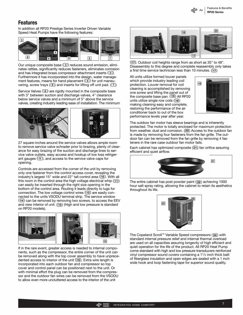
In addition all RP20 Prestige Series Inverter Driven VariableSpeed Heat Pumps have the following features:
Our unique composite base ( ) reduces sound emission, elimi-nates rattles, significantly reduces fasteners, eliminates corrosionand has integrated brass compressor attachment inserts ( ).Furthermore it has incorporated into the design, water manage- ment features, means for hand placement ( ) for unit maneu -vering, screw trays ( ) and inserts for lifting off unit pad. ( )
Service Valves ( ) are rigidly mounted in the composite basewith 3" between suction and discharge valves, 4" clearancebelow service valves and a minimum of 5" above the servicevalves, creating industry leading ease of installation. The minimum
27 square-inches around the service valves allows ample roomto remove service valve schrader prior to brazing, plenty of clear-ance for easy brazing of the suction and discharge lines to ser-vice valve outlets, easy access and hookup of low loss refriger-ant gauges ( ), and access to the service valve caps foropening.
Controls are accessed from the corner of the unit by removingonly one fastener from the control access cover, revealing theindustry’s largest 15" wide and 22" tall control area ( ). With allthis room in the control area the high voltage electrical whip ( )can easily be inserted through the right size opening in the bottom of the control area. Routing it leads directly to lugs forconnection. The low voltage control wires ( ) are easily con-nected to the units VSODU terminal strip. The service window( ) can be removed by removing two screws, to access the EEVand view interior of unit. ( ) (High and low pressure is standardon RP20 models).
If in the rare event, greater access is needed to internal compo-nents, such as the compressor, the entire corner of the unit canbe removed along with the top cover assembly to have unprece-dented access to interior of the unit ( ). Extra wire length isincorporated into each outdoor fan and compressor so topcover and control panel can be positioned next to the unit. Orwith minimal effort the plug can be removed from the compres-sor and the outdoor fan wires can be removed from the VSODUto allow even more uncluttered access to the interior of the unit
( ). Outdoor coil heights range from as short as 35" to 48".Disassembly to this degree and complete reassembly only takesa first time service technician less than 10 minutes. ( )
All units utilize formed louver panelswhich provide industry leading coilprotection. Louver removal for coilcleaning is accomplished by removingone screw and lifting the panel out of the composite base pan. ( ) All RP20units utilize single row coils ( )making cleaning easy and complete, restoring the performance of the airconditioner back to out of the boxperformance levels year after year.
The outdoor fan motor has sleeve bearings and is inherentlyprotected. The motor is totally enclosed for maximum protectionfrom weather, dust and corrosion. ( ) Access to the outdoor fanis made by removing four fasteners from the fan grille. The out-door fan can be removed from the fan grille by removing 4 fas-teners in the rare case outdoor fan motor fails. Each cabinet has optimized composite ( ) fan orifice assuringefficient and quiet airflow.
The entire cabinet has post powder paint ( ) achieving 1000hour salt spray rating, allowing the cabinet to retain its aestheticsthroughout its life.
The Copeland Scroll™ Variable Speed compressors ( ) with standard internal pressure relief and internal thermal overloadare used on all capacities assuring longevity of high efficient andquiet operation for the life of the product. All RP20 Heat Pumpcome standard with high and low pressure transducers reinforcedvinyl compressor sound covers containing a 11/2 inch thick battof fiber glass insulation and open edges are sealed with a 1 inchwide hook and loop fastening tape for superior sound quality.
4
5
76
8
10
11
12
14
15
16
317
17
19
18
20
21
22
28
9
19
22
26
25
2423
21
Features
3
6 6 5 7
4
8
10 13
11129
15
14
18
16
20
17

AirFeatures & BenefitsRP20 Series
8
Each unit is shipped with filter drier for field installation and willtrap any moisture or dirt that could contaminate the refrigerantsystem.
All cabinets have industry leading structural strength due to thecomposite base pan ( ), interlocking corner post ( ), formedcurved louver panels ( ) and drawn top cover ( ) making itthe most durable cabinet on the market today.
Each RP20 capacity has undergone rigorous psychometric test-ing to assure performance ratings of capacity, SEER andEER per AHRI Standard 210/240 rating conditions. Alsoeach unit bears the UL mark and each unit is certified toUL 1995 safety standards.
Each unit has undergone specific strain and modal testing toassure tubing ( ) is outside the units natural frequency and thatthe suction and discharge lines connected to the compressorwithstand any starting, steady state operation, or shut downforces imposed by the compressor.
All units have been sound tested in sound chamber to AHRI 270rating conditions, and A-weighted Sound Power Level tablesproduced, assuring units have acceptable noise qualities (seepage 12). Each unit has been ran in cooling operation at 95°F andsound ratings for the RP20 range from as low as 56 dBA at lowspeed and as high as 76 dBA at 95°F rated conditions.
All units have been ship tested to assure units meet stringent“over the road” shipping conditions.
As manufactured, all units in the RP20 family have cooling capa-bility to 0°F without the addition of an ambient control. Factorytesting is performed on each unit. All component parts meet well defined specification and continually go through receivinginspections. Each component installed on a unit is scanned,assuring correct component utilization for a given unit capacityand voltage. All condenser coils are leak tested with pressuriza-tion test to 550#’s and once installed and assembled, each units’complete refrigerant system is helium leak tested. All units arefully charged from the factory for up to 15 feet of piping. All unitsare factory run tested. The RP20 has a 10-year conditional unitreplacement warranty (registration required) and a 10 year limitedparts warranty.
Required ControlEcoNet Smart Thermostat
The EcoNet Smart Thermostatserves as the hub of communica-tion for a home’s Heating, Coolingand Water Heating systems, and is required to operate an EcoNetEnabled Heating & Cooling system in a fully communicatingmode.
Optional Accessories(Refer to accessory chart for model #)
3"/6"/12"• Gray high density polyethylene feet are available to raise unit
off of mounting surface away from moisture
• Thermistor Kit – RXHT-A02
2423
2625
27
Features (con’t.)
27
RETST700SYS
28
AirModel Number IdentificationRP20 Series
9
RA
2024
AJ
VC
B*
Bran
dPr
oduc
tCa
tego
rySE
ERCa
paci
ty†
BTU
/HR
Maj
or S
erie
s*Vo
ltage
Type
Cont
rols
Min
or S
erie
s**
Opt
ion
Code
Rhe
em A
- Ai
r Con
ditio
ners
13
- 13
SEE
R14
- 14
SEE
R16
- 16
SEE
R17
- 17
SEE
R20
- 20
SEE
R
18 -
18,0
00
[5.2
8 kW
]24
- 24
,000
[7
.03
kW]
30 -
30,0
00
[8.7
9 kW
]36
- 36
,000
[10.
55 k
W]
42 -
42,0
00 [1
2.31
kW
]48
- 48
,000
[14.
07 k
W]
60 -
60,0
00 [1
7.58
kW
]
A - 1
st D
esig
nB
- 2nd
Des
ign
J - 1
ph, 2
08-2
30/6
0C
- 3ph
, 208
-230
/60
1 - S
ingl
e-st
age
2 - T
wo-
stag
eV
- Inv
erte
r
C - C
omm
unic
atin
gN
- N
on-C
omm
unic
atin
gB
- Hig
han
d lo
w
pres
sure
cont
rol
N/A
RP
20
24
AJ
VC
A*
Bran
dPr
oduc
tCa
tego
rySE
ERCa
paci
ty†
BTU
/HR
Maj
or S
erie
s*Vo
ltage
Type
Cont
rols
Min
or S
erie
s**
Opt
ion
Code
Rhe
em
P - H
eat P
ump
13 -
13 S
EER
14 -
14 S
EER
15 -
15 S
EER
16 -
16 S
EER
17 -
17 S
EER
20 -
20 S
EER
18 -
18,0
00
[5.2
8 kW
]24
- 24
,000
[7
.03
kW]
30 -
30,0
00
[8.7
9 kW
]36
- 36
,000
[10.
55 k
W]
42 -
42,0
00 [1
2.31
kW
]48
- 48
,000
[14.
07 k
W]
60 -
60,0
00 [1
7.58
kW
]
A - 1
st D
esig
nB
- 2nd
Des
ign
J - 1
ph, 2
08-2
30/6
0C
- 3ph
, 208
-230
/60
D -
3ph,
460
/60
1 - S
ingl
e-st
age
2 - T
wo-
stag
eV
- Inv
erte
rP
- Pis
ton
C - C
omm
unic
atin
gN
- N
on-C
omm
unic
atin
gA
- 1st
Des
ign
B - 2
nd D
esig
nN
/A
RC
F24
17
SE
AM
CA
*
Bran
dPr
oduc
tCa
tego
ryTy
peCa
paci
tyBT
U/H
RW
idth
Effic
ienc
yM
eter
ing
Dev
ice
Maj
orSe
ries
*O
rien
tatio
nCa
sing
Min
or S
erie
s**
Opt
ion
Code
Rhe
em
C - E
vap
Coil
F - F
urn
Coil
H -
Air-
Han
dler
Coil
24 -
24,0
00
[7.0
3 kW
]36
- 36
,000
[10.
55 k
W]
48 -
48,0
00 [1
4.07
kW
]60
- 60
,000
[17.
58 k
W]
14 -
14"
17 -
17.5
"21
- 21
"24
- 24
.5"
S- S
tand
ard
Eff.
M- M
id E
ff.H
- Hig
h Ef
f.U
- Ultr
a Ef
f.
T-TX
VE-
EEV
P-Pi
ston
A - 1
st D
esig
nM
- M
ultip
oise
V - V
ertic
al o
nly/
conv
ertib
leH
- D
ed.
Hor
izon
tal o
nly
C - C
ased
U -
Unc
ased
A - 1
st D
esig
nN
/A
Heat
Pum
ps (F
or R
efer
ence
)**
Furn
ace
Coils
(For
Ref
eren
ce)*
*
Air C
ondi
tione
rs*
*See
pag
e 3
for a
vaila
ble
SKU’
s.†T
wo-
stag
e an
d in
verte
r ava
ilabl
e in
who
le c
apac
ities
onl
y.
NOTE
: The
abo
ve M
odel
Num
ber I
D’s
are
for r
efer
ence
onl
y. Av
aila
ble
SKU’
s ar
e lis
ted
on th
e st
anda
rd fe
atur
es/a
vaila
ble
SKU
page
of m
odel
spe
c sh
eet.
[ ]
Des
igna
tes
Met
ric
Co
nver
sio
ns
*See
pag
e 3
for a
vaila
ble
SKU’
s.†T
wo-
stag
e an
d in
verte
r ava
ilabl
e in
who
le c
apac
ities
onl
y.

AirModel Number IdentificationRP20 Series
10
R96
VA
70
23
17
MS
A
Bran
dSe
ries
Mot
orM
ajor
Rev
Inpu
tBT
U/H
RSt
ages
Air F
low
Cabi
net
Wid
thCo
nfig
urat
ion
Nox
Min
or R
ev
Rhe
em
90 -
90 A
FUE
92 -
92 A
FUE
95 -
95 A
FUE
96 -
96 A
FUE
97 -
97 A
FUE
98 -
98 A
FUE
V - V
aria
ble
spee
dT
- Con
stan
tTo
rque
(X-1
3)P
- PSC
A - 1
st D
esig
n04
0 -
42,0
00 [1
2.31
kW
]06
0 -
56,0
00 [1
6.41
kW
]07
0 -
70,0
00 [2
0.51
kW
]08
5 -
84,0
00 [2
4.62
kW
]10
0 -
98,0
00 [2
8.72
kW
]11
5 - 1
12,0
00 [3
2.82
kW
]
1-S
ingl
e-st
age
2-T
wo-
stag
eM
- M
odul
atin
g
3 - u
p to
3 to
n5
- 3 1
/2 u
p to
5 to
n14
- 14
"17
- 17
.5"
21 -
21"
24 -
24.5
"
M -
Mul
tiX
- Low
Nox
S - S
tand
ard
A - 1
st D
esig
n
R80
2V
A07
53
17M
SA
Bran
dSe
ries
Stag
esM
otor
Maj
or R
evIn
put
BTU
/HR
Air F
low
Cabi
net
Wid
thCo
nfig
urat
ion
Nox
Min
or R
ev
Rhe
em
80 -
80+
AFU
E1
- Sin
gle-
stag
e2
- Tw
o-st
age
V - V
aria
ble
spee
dT
- Con
stan
t Tor
que
(X-1
3)P
- PSC
pre
miu
mS
- PSC
sta
ndar
d
A - 1
st D
esig
n05
0 -
50,0
00 [1
5 kW
]07
5 -
75,0
00 [2
2 kW
]10
0 - 1
00,0
00 [2
9 kW
]12
5 - 1
25,0
00 [3
7 kW
]15
0 - 1
50,0
00 [4
4 kW
]
3 - u
p to
3 to
n4
- 2 1
/2 to
4 to
n5
- 3 1
/2 u
p to
5 to
n
14 -
14"
17 -
17.5
"21
- 21
"24
- 24
.5"
M- M
ulti
D- D
own
Z- D
own
&ze
ro c
lear
ance
dow
n flo
w
X - L
ow N
oxS
- Sta
ndar
dA
- 1st
Des
ign
RH
MV
3617
SE
AC
JA
000
*
Bran
dPr
oduc
tCa
tego
rySt
ages
of
Airf
low
Mot
or T
ype
Capa
city
BTU
/HR
Wid
thCo
il Si
zeM
eter
ing
Dev
ice
Maj
orSe
ries
*Co
ntro
lsVo
ltage
Min
orSe
ries
**Fa
ctor
y H
eat
Cap
Opt
ion
Code
Rhe
em
H -
Air
Han
dler
1 - S
ingl
e-St
age
2 - T
wo-
Stag
eM
- M
odul
atin
g
V - V
aria
ble
Spee
dT
- Con
stan
tTo
rque
P - P
SC
24 -
24,0
00
[7.0
3 kW
]36
- 36
,000
[10.
55 k
W]
48 -
48,0
00 [1
4.07
kW
]60
- 60
,000
[17.
58 k
W]
14 -
14"
17 -
17.5
"21
- 21
"24
- 24
.5"
S - S
tand
ard
Eff.
M -
Mid
Eff.
H -
Hig
h Ef
f.
T - T
EVE
- EEV
P - P
isto
n
A - 1
st D
esig
nC
-Com
mun
icat
ing
N -N
on-c
omm
J- 1
ph, 2
08-2
40/6
0A
- 1st
Des
ign
00 -
nofa
ctor
y he
atw
ith o
ptio
nco
de
*TBD
90%
+ A
FUE
Gas
Furn
aces
(For
Ref
eren
ce)*
*
80%
AFU
E Ga
s Fu
rnac
es (F
or R
efer
ence
)**
Air H
andl
ers
(For
Ref
eren
ce)*
*
NOTE
: The
abo
ve M
odel
Num
ber I
D’s
are
for r
efer
ence
onl
y. Av
aila
ble
SKU’
s ar
e lis
ted
on th
e st
anda
rd fe
atur
es/a
vaila
ble
SKU
page
of m
odel
spe
c sh
eet.
[ ]
Des
igna
tes
Met
ric
Co
nver
sio
ns
AirGeneral Data/Electrical DataRP20 Series
11
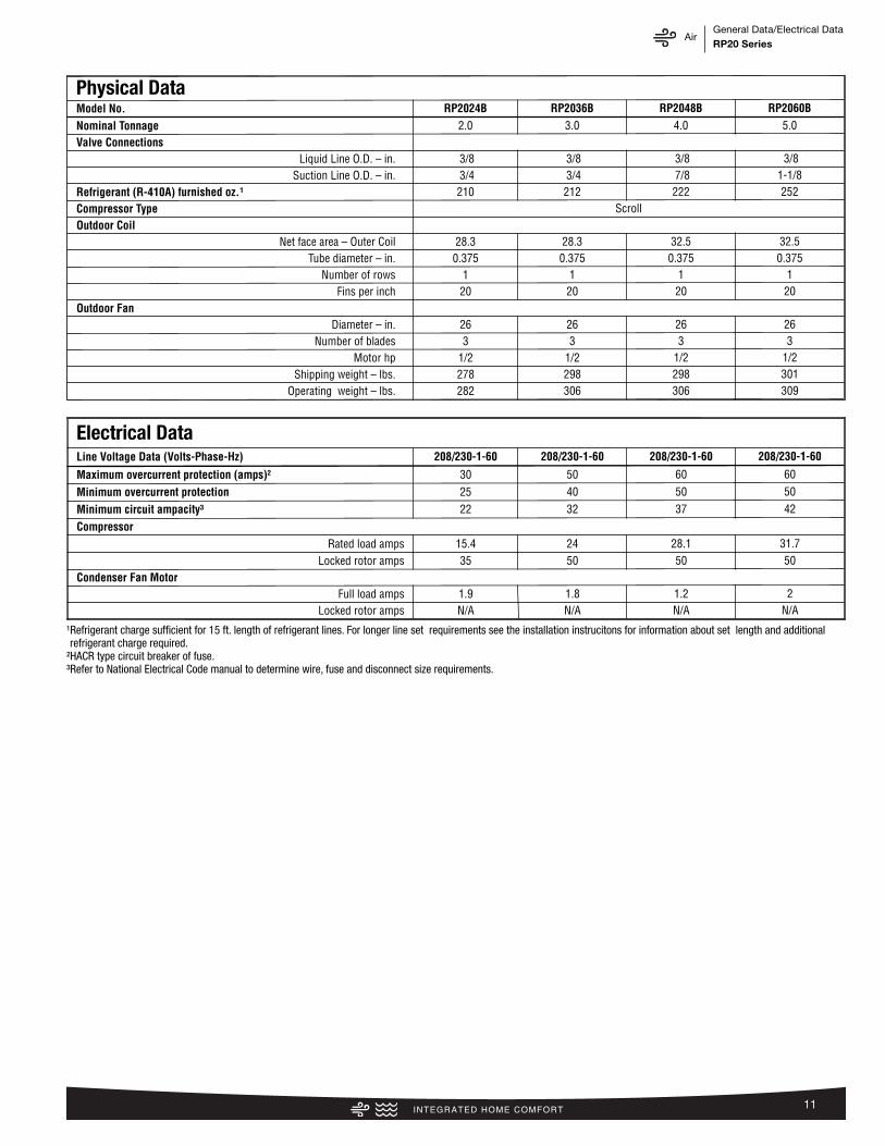
Physical DataModel No. RP2024B RP2036B RP2048B RP2060B
Nominal Tonnage 2.0 3.0 4.0 5.0Valve Connections
Liquid Line O.D. – in. 3/8 3/8 3/8 3/8Suction Line O.D. – in. 3/4 3/4 7/8 1-1/8
Refrigerant (R-410A) furnished oz.¹ 210 212 222 252Compressor Type ScrollOutdoor Coil
Net face area – Outer Coil 28.3 28.3 32.5 32.5Tube diameter – in. 0.375 0.375 0.375 0.375
Number of rows 1 1 1 1Fins per inch 20 20 20 20
Outdoor FanDiameter – in. 26 26 26 26
Number of blades 3 3 3 3Motor hp 1/2 1/2 1/2 1/2
Shipping weight – lbs. 278 298 298 301Operating weight – lbs. 282 306 306 309
Electrical DataLine Voltage Data (Volts-Phase-Hz) 208/230-1-60 208/230-1-60 208/230-1-60 208/230-1-60
Maximum overcurrent protection (amps)² 30 50 60 60
Minimum overcurrent protection 25 40 50 50
Minimum circuit ampacity³ 22 32 37 42
Compressor Rated load amps 15.4 24 28.1 31.7
Locked rotor amps 35 50 50 50Condenser Fan Motor
Full load amps 1.9 1.8 1.2 2Locked rotor amps N/A N/A N/A N/A
¹Refrigerant charge sufficient for 15 ft. length of refrigerant lines. For longer line set requirements see the installation instrucitons for information about set length and additionalrefrigerant charge required.
²HACR type circuit breaker of fuse.³Refer to National Electrical Code manual to determine wire, fuse and disconnect size requirements.
AirAccessories/Weighted Sound PowerRP20 Series
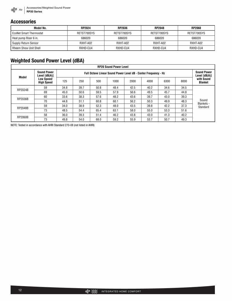
12
AccessoriesModel No. RP2024 RP2036 RP2048 RP2060
EcoNet Smart Thermostat RETST700SYS RETST700SYS RETST700SYS RETST700SYS
Heat pump Riser 6 in. 686020 686020 686020 686020
Supply Return Sensor RXHT-A02 RXHT-A02 RXHT-A02 RXHT-A02
Rheem Show Unit Shell RXHD-CU4 RXHD-CU4 RXHD-CU4 RXHD-CU4
Weighted Sound Power Level (dBA)RP20 Sound Power Level
Model
Sound PowerLevel [dB(A)]Low Speed/High Speed
Full Octave Linear Sound Power Level dB - Center Frequency - Hz Sound PowerLevel [dB(A)]with Sound
Blanket125 250 500 1000 2000 4000 6300 8000
RP2024B59 34.8 39.7 50.8 48.4 42.5 40.2 34.6 34.5
Sound Blankets -Standard
69 45.0 50.6 59.5 57.9 56.6 49.5 45.7 44.8
RP2036B60 33.6 38.3 57.6 48.2 43.6 39.7 43.0 39.370 44.8 51.1 60.8 60.1 56.2 50.3 49.9 48.3
RP2048B59 34.0 38.9 52.3 48.0 43.5 39.8 42.2 37.373 48.5 54.4 65.4 63.1 58.0 55.0 53.3 51.6
RP2060B58 36.0 39.3 51.4 46.2 43.8 43.0 41.3 40.273 49.8 54.0 68.0 59.2 55.9 53.7 50.7 49.3
NOTE: Tested in accordance with AHRI Standard 270-08 (not listed in AHRI)

AirSmart Home SystemsRP20 Series
13
RETST700SYS
THE ECONET® SMART THERMOSTAT
BUILT-IN WIFI
4.3� LCD TOUCH SCREEN
LOCAL WEATHER – Current conditions plus 6-day forecast
5 OPERATING MODES – Heat, Cool, Auto, Emergency Heat and Fan Only
7-DAY PROGRAMMABLE SCHEDULE – Offers comfort without thought
ONE-TOUCH AWAY – Quickly switch to your energy-saving away preferences
VACATION SCHEDULING – Allows you to save while you’re away and come home to comfort
MOTION SENSOR – Automatically wakes the screen as you approach
STANDBY SCREEN – Displays indoor temperature and current weather
OPERATIONAL FEATURES
AUTOMATIC CHANGEOVER – Transitions between heating and cooling automatically to keep the house comfortable
INTEGRATED WATER CONTROL – Enables easy water heater management
SMOOTH ARRIVAL – Prompts the system to start ahead of schedule to ensure the home is at the desired temperature at the scheduled time
HUMIDITY CONTROL – Supports humidifier accessories or over-cool based dehumidification
DETAILED OPERATING STATUS – View pertinent equipment status information and run times
CONTINUOUS FAN – Offers 5 speeds (Low, Medium Low, Medium, Medium High, High)
SHORT-CYCLE PROTECTION – Avoids damage to equipment from short run cycles
MONITORING & REMOTE CONTROL FEATURES
ACTIVE MONITORING – Alerts to problems that need immediate attention
REMOTE CONTROL – Allows adjusting of comfort and settings from anywhere using a mobile device
SERVICE ALERTS – Sends routine maintenance reminders
AIR FILTER MONITORING – Detects when it’s time to replace the air filter
ALARM HISTORY – Displays time-stamped alarm codes with clear descriptions
Heating & Cooling
ModelsGas Furnaces Air Handlers Air Conditioners Heat Pumps
R802V R96V R97V R98V RHMV RH2T RA20 RA17* RP20 RP17
RETST700SYS ✔ ✔ ✔ ✔ ✔ ✔ ✔ ✔ ✔ ✔
*Models not EcoNet Enabled: RA1724AJ2NB, RA1736AJ2NB, RA1748AJ2NB, RA1760AJ2NB
ECONET SMART THERMOSTAT COMPATIBILITY

14
AirUnit DimensionsRP20 Series
Unit Dimensions
MODELNO.
OPERATING SHIPPING
H (Height) L (Length) W (Width) H (Height) L (Length) W (Width)
INCHES mm INCHES mm INCHES mm INCHES mm INCHES mm INCHES mm
RP2024 39 990 35.75 908 35.75 908 41.56 1056 39.37 999 39.64 1006
RP2036 39 990 35.75 908 35.75 908 53.56 1360 39.37 999 39.64 1006
RP2048 51 1295 35.75 908 35.75 908 53.56 1360 39.37 999 39.64 1006
RP2060 51 1295 35.75 908 35.75 908 53.56 1360 39.37 999 39.64 1006
[ ] Designates Metric Conversions ST-A1226-02-00

15
AirClearancesRP20 Series
6�
(152
.4)
24�
(609
.6)
Ser
vice
12�
(304
.8)
6�
(152
.4)
24�
(609
.6)
Ser
vice
24�
(609
.6)
24�
reco
mm
ende
d6�
min
imum
12�
(304
.8)
12�
(304
.8)
6�
(152
.4)
24�
(609
.6)
Ser
vice
24�
(609
.6)
Ser
vice
24�
(609
.6)
Ser
vice
18�
(457
.2)
WA
LL
WA
LL
WA
LL
WALL
NO
TE
: NU
MB
ER
S IN
()
= m
m
CLEARANCES
IMPO
RTA
NT:
Whe
n in
stal
ling
mul
tiple
uni
ts in
an
alco
ve, r
oof w
ell o
r par
tially
enc
lose
d ar
ea, e
nsur
e th
ere
is a
dequ
ate
vent
illatio
n to
pre
vent
re-c
ircul
atio
n of
dis
char
ge a
ir.
ST-
A12
25-0
1-00
24�
(609
.6)
24�
reco
mm
ende
d6�
min
imum

AirRefrigerant Line Size InformationRP20 Series
16
20 SEER Variable Speed Heat Pumps
Unit SizeAllowable
Liquid Line Size
Allowable Vapor
Line Size
Outdoor Unit ABOVE or BELOW Indoor UnitEquivalent Length (Feet)
< 25 26-50 51-75 76-100 101-125 126-150
Maximum Vertical Separation/Capacity Multiplier
2.0 Ton*SEE NOTE 3
1/4" 5/8" 25/1.00 50/0.99 33/0.98 60/0.97 NR NR
5/16" 5/8" 25/1.00 50/0.99 50/0.98 50/0.97 50/0.96 50/0.95
3/8" 5/8" 25/1.00 50/0.99 50/0.98 50/0.97 50/0.96 50/0.95
1/4" *3/4"* 25/1.00 50/1.00 33/0.99 60/0.99 NR NR
5/16" *3/4"* 25/1.00 50/1.00 50/0.99 50/0.99 50/0.99 50/0.98
3/8" *3/4"* 25/1.00 50/1.00 50/0.99 50/0.99 50/0.99 50/0.98
3 Ton
5/16" 5/8" 25/0.99 50/0.97 50/0.95 50/0.93 36/0.91 NR
3/8" 5/8" 25/0.99 50/0.97 50/0.95 50/0.93 50/0.91 NR
5/16" 3/4" 25/1.00 50/0.99 50/0.99 50/0.98 36/0.97 20/0.96
3/8" 3/4" 25/1.00 50/0.99 50/0.99 50/0.98 50/0.97 50/0.96
1/2" 3/4" 25/1.00 50/0.99 50/0.99 50/0.98 50/0.97 50/0.96
4 Ton
3/8" 3/4" 25/0.99 50/0.98 50/0.96 50/0.95 50/0.93 50/0.92
1/2" 3/4" 25/0.99 50/0.98 50/0.96 50/0.95 50/0.93 50/0.92
3/8" 7/8" 25/1.00 50/0.99 50/0.99 50/0.98 50/0.98 50/0.97
1/2" 7/8" 25/1.00 50/0.99 50/0.99 50/0.98 50/0.98 50/0.97
5 Ton
3/8" 3/4" 25/0.98 50/0.97 50/0.95 50/0.93 46/0.91 NR
1/2" 3/4" 25/0.98 50/0.97 50/0.95 50/0.93 50/0.91 NR
3/8" 7/8" 25/0.99 50/0.99 50/0.98 50/0.97 50/0.96 38/0.95
1/2" 7/8" 25/0.99 50/0.99 50/0.98 50/0.97 50/0.96 50/0.95
3/8" **1-1/8"** 25/1.00 50/1.00 50/1.00 50/0.99 50/0.99 38/0.99
1/2" **1-1/8"** 25/1.00 50/1.00 50/1.00 50/0.99 50/0.99 50/0.99
Refrigerant Line Sizing Chart (English Units)
NOTES:
1. Do not exceed 150 ft linear line length.
2. Do not exceed 50 ft vertical separation between indoor and outdoor units.
3. *3/4" vapor line should only be used for 2 ton systems if outdoor unit is below or at same level as indoor unit to assure proper oil return.
4. **1-1/8" vapor line should only be used for 5 ton systems if outdoor unit is below or at same level as indoor unit to assure proper oil return.
5. Always use the smallest liquid line allowable to minimize refrigerant charge.
6. Applications shaded in light gray indicate capacity multipliers between 0.90 and 0.96 which are not recommended, but are allowed.
7. Applications shaded in dark gray are not recommended due to excessive liquid or suction pressure drop.

AirRefrigerant Line Size InformationRP20 Series
17
20 SEER Variable Speed Heat Pumps
Unit SizeAllowable
Liquid Line Size
Allowable Vapor
Line Size
Outdoor Unit ABOVE or BELOW Indoor UnitEquivalent Length (Meters)
< 8 8-15 16-23 24-30 31-38 39-46
Maximum Vertical Separation/Capacity Multiplier
7.0 kW[2.0 Ton]
*SEE NOTE 3
6.35 [1/4] 15.88 [5/8] 8/1.00 15/0.99 10/0.98 20/0.97 NR NR
7.94 [5/16] 15.88 [5/8] 8/1.00 15/0.99 15/0.98 15/0.97 15/0.96 15/0.95
9.53 [3/8] 15.88 [5/8] 8/1.00 15/0.99 15/0.98 15/0.97 15/0.96 15/0.95
6.35 [1/4] 19.05 [3/4] 8/1.00 15/0.99 10/0.99 20/0.99 NR NR
7.94 [5/16] 19.05 [3/4] 8/1.00 15/0.99 15/0.99 15/0.99 15/0.99 15/0.98
9.53 [3/8] 19.05 [3/4] 8/1.00 15/0.99 15/0.99 15/0.99 15/0.99 15/0.98
10.6 kW[3 Ton]
7.94 [5/16] 15.88 [5/8] 8/0.99 15/0.97 15/0.95 15/0.93 11/0.91 NR
9.53 [3/8] 15.88 [5/8] 8/0.99 15/0.97 15/0.95 15/0.93 15/0.91 NR
7.94 [5/16] 19.05 [3/4] 8/1.00 15/0.99 15/0.99 15/0.98 11/0.97 6/0.96
9.53 [3/8] 19.05 [3/4] 8/1.00 15/0.99 15/0.99 15/0.98 15/0.97 15/0.96
12.7 [1/2] 19.05 [3/4] 8/1.00 15/0.99 15/0.99 15/0.98 15/0.97 15/0.96
14.1 kW[4 Ton]
9.53 [3/8] 19.05 [3/4] 8/0.99 15/0.98 15/0.96 15/0.95 15/0.93 15/0.92
12.7 [1/2] 19.05 [3/4] 8/0.99 15/0.98 15/0.96 15/0.95 15/0.93 15/0.92
9.53 [3/8] 22.23 [7/8] 8/1.00 15/0.99 15/0.99 15/0.98 15/0.98 15/0.97
12.7 [1/2] 22.23 [7/8] 8/1.00 15/0.99 15/0.99 15/0.98 15/0.98 15/0.97
17.6 kW[5 Ton]
9.53 [3/8] 19.05 [3/4] 8/0.98 15/0.97 15/0.95 15/0.93 14/0.91 NR
12.7 [1/2] 19.05 [3/4] 8/0.98 15/0.97 15/0.95 15/0.93 15/0.91 NR
9.53 [3/8] 22.23 [7/8] 8/0.99 15/0.99 15/0.98 15/0.97 15/0.96 12/0.95
12.7 [1/2] 22.23 [7/8] 8/0.99 15/0.99 15/0.98 15/0.97 15/0.96 15/0.95
9.53 [3/8] **28.58 [1-1/8]** 8/1.00 15/1.00 15/1.00 15/0.99 15/0.99 12/0.99
12.7 [1/2] **28.58 [1-1/8]** 8/1.00 15/1.00 15/1.00 15/0.99 15/0.99 15/0.99
Refrigerant Line Sizing Chart (Metric Units)
NOTES:
1. Do not exceed 46 meters linear line length.
2. Do not exceed 15 meters vertical separation between indoor and outdoor units.
3. *19.05mm [3/4 in.] vapor line should only be used for 2 ton systems if outdoor unit is below or at same level as indoor unit to assure proper oil return.
4. **28.58mm [1-1/8 in.] vapor line should only be used for 5 ton systems if outdoor unit is below or at same level as indoor unit to assure proper oil return.
5. Always use the smallest liquid line allowable to minimize refrigerant charge.
6. Applications shaded in light gray indicate capacity multipliers between 0.90 and 0.96 which are not recommended, but are allowed.
7. Applications shaded in dark gray are not recommended due to excessive liquid or suction pressure drop.
AirCapacity RangesRP20 Series
18
0.0
1.5
2.9
4.4
5.9
7.4
8.8
10.3
0
5,000
10,000
15,000
20,000
25,000
30,000
35,000
60° [16°] 70° [21°] 80° [27°] 90° [32°] 100° [38°] 110° [43]
KWBTU
H
OUTDOOR DB °F [°C]
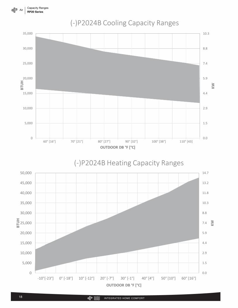
(-)P2024B Cooling Capacity Ranges
0.0
1.5
2.9
4.4
5.9
7.4
8.8
10.3
11.8
13.2
14.7
0
5,000
10,000
15,000
20,000
25,000
30,000
35,000
40,000
45,000
50,000
-10°[-23°] 0° [-18°] 10° [-12°] 20° [-7°] 30° [-1°] 40° [4°] 50° [10°] 60° [16°]
KWBTU
H
OUTDOOR DB °F [°C]
(-)P2024B Heating Capacity Ranges

AirCapacity RangesRP20 Series
19
0.0
1.5
2.9
4.4
5.9
7.4
8.8
10.3
11.8
13.2
14.7
0
5,000
10,000
15,000
20,000
25,000
30,000
35,000
40,000
45,000
50,000
60° [16°] 70° [21°] 80° [27°] 90° [32°] 100° [38°] 110° [43]
KW
BTU
H
Outdoor DB °F [°C]
(-)P2036B Cooling Capacity Ranges
0.0
2.9
5.9
8.8
11.7
14.7
17.6
20.5
23.4
0
10,000
20,000
30,000
40,000
50,000
60,000
70,000
80,000
-10°[-23°] 0° [-18°] 10° [-12°] 20° [-7°] 30° [-1°] 40° [4°] 50° [10°] 60° [16°]
KW
BTU
H
Outdoor DB °F [°C]
(-)P2036B Heating Capacity Ranges

AirCapacity RangesRP20 Series
20
0.0
2.9
5.9
8.8
11.7
14.7
17.6
0
10,000
20,000
30,000
40,000
50,000
60,000
60° [16°] 70° [21°] 80° [27°] 90° [32°] 100° [38°] 110° [43]
KWBTU
H
Outdoor DB °F [°C]
(-)P2048B Cooling Capacity Ranges
0.0
2.9
5.9
8.8
11.7
14.7
17.6
20.5
23.4
0
10,000
20,000
30,000
40,000
50,000
60,000
70,000
80,000
-10°[-23°] 0° [-18°] 10° [-12°] 20° [-7°] 30° [-1°] 40° [4°] 50° [10°] 60° [16°]
KWBTU
H
Outdoor DB °F [°C]
(-)2048B Heating Capacity Ranges
AirCapacity RangesRP20 Series
21
0.0
2.9
5.9
8.8
11.7
14.7
17.6
20.5
23.4
0
10,000
20,000
30,000
40,000
50,000
60,000
70,000
80,000
60° [16°] 70° [21°] 80° [27°] 90° [32°] 100° [38°] 110° [43°]
KWBTU
H
Outdoor DB °F [°C]
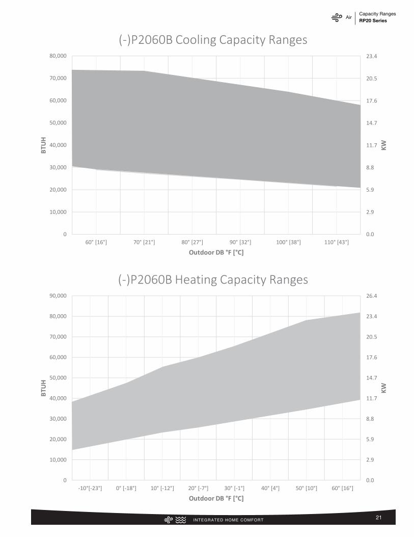
(-)P2060B Cooling Capacity Ranges
0.0
2.9
5.9
8.8
11.7
14.7
17.6
20.5
23.4
26.4
0
10,000
20,000
30,000
40,000
50,000
60,000
70,000
80,000
90,000
-10°[-23°] 0° [-18°] 10° [-12°] 20° [-7°] 30° [-1°] 40° [4°] 50° [10°] 60° [16°]
KWBTU
H
Outdoor DB °F [°C]
(-)P2060B Heating Capacity Ranges
AirPerformance DataRP20 Series
22
Perf
orm
ance
Dat
a @
AHR
I Sta
ndar
d Co
nditi
ons
–He
at P
ump
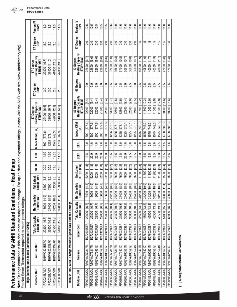
Hig
h Sa
les
Volu
me
Test
ed C
ombi
natio
n (H
SVTC
)
Out
door
Uni
tAi
r Han
dler
Tota
l Cap
acity
BTU
/H [k
W]
Net
Sen
sibl
eBT
U/H
[kW
]N
et L
aten
tBT
U/H
[kW
]SE
EREE
RIn
door
CFM
[L/s
]47
Deg
ree
Hea
ting
Capa
city
BTU
/H [k
W]
47 D
egre
eCO
P
17 D
egre
eH
eatin
g Ca
paci
tyBT
U/H
[kW
]
17 D
egre
eCO
PR
egio
n IV
HSP
F
RP2
024B
JVCA
RH
MV2
421U
EAC
2280
0 [6
.7]
1660
0 [4
.9]
6200
[1
.8]
20.0
14.0
080
0 [3
77.6
]22
400
[6.6
]3.
022
800
[6.7
]2.
011
.0
RP2
036B
JVCA
RH
MV6
021S
EAC
3500
0 [1
0.3]
2740
0 [8
.0]
7600
[2
.2]
20.0
14.0
012
25 [5
78.1
]33
000
[9.7
]3.
037
400
[11.
0]2.
011
.5
RP2
048B
JVCA
RH
MV6
021S
EAC
4550
0 [1
3.3]
3420
0 [1
0.0]
1130
0 [3
.3]
19.5
12.5
015
75 [7
43.3
]42
000
[12.
3]2.
541
000
[12.
0]2.
011
.0
RP2
060B
JVCA
RH
MV6
021S
EAC
5400
0 [1
5.8]
3900
0 [1
1.4]
1500
0 [4
.4]
19.5
11.5
017
00 [8
02.3
]51
000
[14.
9]2.
547
000
[13.
8]1.
511
.0
R80
2V:
80%
AFU
E 2-
Stag
e Va
riab
le S
peed
Gas
Fur
nace
Rat
ings
Out
door
Uni
tFu
rnac
eIn
door
Coi
lTo
tal C
apac
ityBT
U/H
[kW
]N
et S
ensi
ble
BTU
/H [k
W]
Net
Lat
ent
BTU
/H [k
W]
SEER
EER
Indo
or C
FM[L
/s]
47 D
egre
eH
eatin
g Ca
paci
tyBT
U/H
[kW
]
47 D
egre
eCO
P
17 D
egre
eH
eatin
g Ca
paci
tyBT
U/H
[kW
]
17 D
egre
eCO
PR
egio
n IV
HSP
F
RP20
24BJ
VCA
R80
2VA0
5031
7MR
CF24
21U
EA22
600
[6.6
]16
400
[4.8
]62
00
[1.8
]19
.513
.080
0 [3
77.6
]22
000
[6.4
]3.
022
800
[6.7
]2.
010
.5
RP20
24BJ
VCA
R80
2VA0
7531
7MR
CF24
21U
EA22
800
[6.7
]16
600
[4.9
]62
00
[1.8
]20
.014
.080
0 [3
77.6
]22
000
[6.4
]3.
022
600
[6.6
]2.
010
.5
RP20
24BJ
VCA
R80
2VA0
7542
1ZR
CF24
21U
EA22
800
[6.7
]16
600
[4.9
]62
00
[1.8
]20
.014
.080
0 [3
77.6
]22
000
[6.4
]3.
022
600
[6.6
]2.
010
.5
RP20
24BJ
VCA
R80
2VA1
0052
1MR
CF24
21U
EA22
800
[6.7
]16
600
[4.9
]62
00
[1.8
]20
.014
.080
0 [3
77.6
]21
800
[6.4
]3.
022
600
[6.6
]2.
010
.5
RP20
24BJ
VCA
R80
2VA1
0052
1ZR
CF24
21U
EA22
800
[6.7
]16
600
[4.9
]62
00
[1.8
]20
.014
.080
0 [3
77.6
]22
000
[6.4
]3.
022
600
[6.6
]2.
010
.5
RP20
36BJ
VCA
R80
2VA0
5031
7MR
CF60
21SE
A34
600
[10.
1]27
200
[8.0
]74
00
[2.2
]19
.513
.012
25 [5
78.1
]33
000
[9.7
]2.
537
400
[11.
0]2.
010
.5
RP20
36BJ
VCA
R80
2VA0
7531
7MR
CF60
21SE
A34
800
[10.
2]27
200
[8.0
]76
00
[2.2
]19
.513
.012
25 [5
78.1
]32
600
[9.6
]2.
536
800
[10.
8]2.
011
.0
RP20
36BJ
VCA
R80
2VA0
7542
1ZR
CF60
21SE
A35
000
[10.
3]27
400
[8.0
]76
00
[2.2
]19
.513
.012
25 [5
78.1
]32
800
[9.6
]2.
537
000
[10.
8]2.
011
.0
RP20
36BJ
VCA
R80
2VA1
0052
1MR
CF60
21SE
A35
000
[10.
3]27
400
[8.0
]76
00
[2.2
]20
.014
.012
25 [5
78.1
]32
200
[9.4
]3.
036
600
[10.
7]2.
011
.0
RP20
36BJ
VCA
R80
2VA1
0052
1ZR
CF60
21SE
A35
000
[10.
3]27
400
[8.0
]76
00
[2.2
]19
.513
.012
25 [5
78.1
]32
600
[9.6
]2.
536
800
[10.
8]2.
011
.0
RP20
36BJ
VCA
R80
2VA1
2552
4MR
CF60
21SE
A35
000
[10.
3]27
400
[8.0
]76
00
[2.2
]19
.513
.012
25 [5
78.1
]32
400
[9.5
]3.
036
600
[10.
7]2.
011
.0
RP20
48BJ
VCA
R80
2VA0
7542
1MR
CF60
21SE
A45
500
[13.
3]34
200
[10.
0]11
300
[3.3
]19
.012
.015
75 [7
43.3
]41
500
[12.
2]2.
540
500
[11.
9]1.
511
.0
RP20
48BJ
VCA
R80
2VA0
7542
1ZR
CF60
21SE
A45
500
[13.
3]34
200
[10.
0]11
300
[3.3
]18
.511
.515
75 [7
43.3
]41
500
[12.
2]2.
540
500
[11.
9]1.
511
.0
RP20
48BJ
VCA
R80
2VA1
0052
1MR
CF60
21SE
A45
500
[13.
3]34
200
[10.
0]11
300
[3.3
]19
.512
.515
75 [7
43.3
]41
000
[12.
0]2.
540
000
[11.
7]1.
511
.0
RP20
48BJ
VCA
R80
2VA1
0052
1ZR
CF60
21SE
A45
500
[13.
3]34
200
[10.
0]11
300
[3.3
]18
.512
.015
75 [7
43.3
]41
000
[12.
0]2.
540
500
[11.
9]1.
511
.0
RP20
48BJ
VCA
R80
2VA1
2552
4MR
CF60
21SE
A45
500
[13.
3]34
200
[10.
0]11
300
[3.3
]19
.012
.515
75 [7
43.3
]41
000
[12.
0]2.
540
000
[11.
7]1.
511
.0
RP20
60BJ
VCA
R80
2VA1
0052
1ZR
CF60
21SE
A54
000
[15.
8]39
000
[11.
4]15
000
[4.4
]18
.511
.517
00 [8
02.3
]50
000
[14.
6]2.
547
000
[13.
8]1.
511
.0
RP20
60BJ
VCA
R80
2VA1
2552
4ZR
CF60
21SE
A54
000
[15.
8]39
000
[11.
4]15
000
[4.4
]18
.511
.517
00 [8
02.3
]50
000
[14.
6]2.
547
000
[13.
8]1.
511
.0
[ ]
Des
igna
tes
Met
ric
Co
nver
sio
ns
No
te: R
atin
gs c
onta
ined
in t
his
doc
umen
t ar
e su
bje
ct t
o ch
ange
. For
up
-to-
dat
e an
d e
xpan
ded
rat
ings
, ple
ase
visi
t th
e A
HR
I web
site
(ww
w.a
hrid
irect
ory.
org)
.E
coN
et S
mar
t Th
erm
osta
t re
qui
red
to
reac
h p
oste
d r
atin
gs.
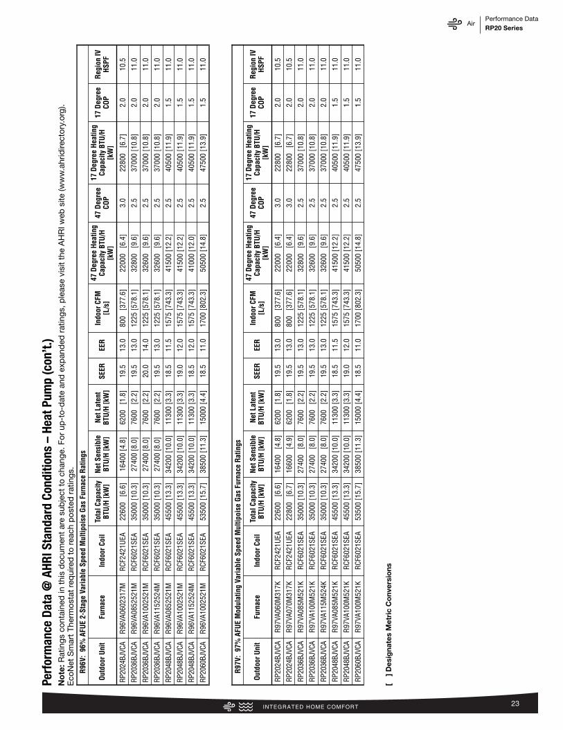
AirPerformance DataRP20 Series
23
Perf
orm
ance
Dat
a @
AHR
I Sta
ndar
d Co
nditi
ons
–He
at P
ump
(con
’t.)
R96
V: 9
6% A
FUE
2-St
age
Vari
able
Spe
ed M
ultip
oise
Gas
Fur
nace
Rat
ings
Out
door
Uni
tFu
rnac
eIn
door
Coi
lTo
tal C
apac
ityBT
U/H
[kW
]N
et S
ensi
ble
BTU
/H [k
W]
Net
Lat
ent
BTU
/H [k
W]
SEER
EER
Indo
or C
FM[L
/s]
47 D
egre
e H
eatin
gCa
paci
ty B
TU/H
[kW
]
47 D
egre
eCO
P
17 D
egre
e H
eatin
gCa
paci
ty B
TU/H
[kW
]
17 D
egre
eCO
PR
egio
n IV
HSP
F
RP20
24BJ
VCA
R96
VA06
0231
7MR
CF24
21U
EA22
600
[6.6
]16
400
[4.8
]62
00
[1.8
]19
.513
.080
0 [3
77.6
]22
000
[6.4
]3.
022
800
[6.7
]2.
010
.5
RP20
36BJ
VCA
R96
VA08
5252
1MR
CF60
21SE
A35
000
[10.
3]27
400
[8.0
]76
00
[2.2
]19
.513
.012
25 [5
78.1
]32
800
[9.6
]2.
537
000
[10.
8]2.
011
.0
RP20
36BJ
VCA
R96
VA10
0252
1MR
CF60
21SE
A35
000
[10.
3]27
400
[8.0
]76
00
[2.2
]20
.014
.012
25 [5
78.1
]32
600
[9.6
]2.
537
000
[10.
8]2.
011
.0
RP20
36BJ
VCA
R96
VA11
5252
4MR
CF60
21SE
A35
000
[10.
3]27
400
[8.0
]76
00
[2.2
]19
.513
.012
25 [5
78.1
]32
600
[9.6
]2.
537
000
[10.
8]2.
011
.0
RP20
48BJ
VCA
R96
VA08
5252
1MR
CF60
21SE
A45
500
[13.
3]34
200
[10.
0]11
300
[3.3
]18
.511
.515
75 [7
43.3
]41
500
[12.
2]2.
540
500
[11.
9]1.
511
.0
RP20
48BJ
VCA
R96
VA10
0252
1MR
CF60
21SE
A45
500
[13.
3]34
200
[10.
0]11
300
[3.3
]19
.012
.015
75 [7
43.3
]41
500
[12.
2]2.
540
500
[11.
9]1.
511
.0
RP20
48BJ
VCA
R96
VA11
5252
4MR
CF60
21SE
A45
500
[13.
3]34
200
[10.
0]11
300
[3.3
]18
.512
.015
75 [7
43.3
]41
000
[12.
0]2.
540
500
[11.
9]1.
511
.0
RP20
60BJ
VCA
R96
VA10
0252
1MR
CF60
21SE
A53
500
[15.
7]38
500
[11.
3]15
000
[4.4
]18
.511
.017
00 [8
02.3
]50
500
[14.
8]2.
547
500
[13.
9]1.
511
.0
R97
V: 9
7% A
FUE
Mod
ulat
ing
Vari
able
Spe
ed M
ultip
oise
Gas
Fur
nace
Rat
ings
Out
door
Uni
tFu
rnac
eIn
door
Coi
lTo
tal C
apac
ityBT
U/H
[kW
]N
et S
ensi
ble
BTU
/H [k
W]
Net
Lat
ent
BTU
/H [k
W]
SEER
EER
Indo
or C
FM[L
/s]
47 D
egre
e H
eatin
gCa
paci
ty B
TU/H
[kW
]
47 D
egre
eCO
P
17 D
egre
e H
eatin
gCa
paci
ty B
TU/H
[kW
]
17 D
egre
eCO
PR
egio
n IV
HSP
F
RP20
24BJ
VCA
R97
VA06
0M31
7KR
CF24
21U
EA22
600
[6.6
]16
400
[4.8
]62
00
[1.8
]19
.513
.080
0 [3
77.6
]22
000
[6.4
]3.
022
800
[6.7
]2.
010
.5
RP20
24BJ
VCA
R97
VA07
0M31
7KR
CF24
21U
EA22
800
[6.7
]16
600
[4.9
]62
00
[1.8
]19
.513
.080
0 [3
77.6
]22
000
[6.4
]3.
022
800
[6.7
]2.
010
.5
RP20
36BJ
VCA
R97
VA08
5M52
1KR
CF60
21SE
A35
000
[10.
3]27
400
[8.0
]76
00
[2.2
]19
.513
.012
25 [5
78.1
]32
800
[9.6
]2.
537
000
[10.
8]2.
011
.0
RP20
36BJ
VCA
R97
VA10
0M52
1KR
CF60
21SE
A35
000
[10.
3]27
400
[8.0
]76
00
[2.2
]19
.513
.012
25 [5
78.1
]32
600
[9.6
]2.
537
000
[10.
8]2.
011
.0
RP20
36BJ
VCA
R97
VA11
5M52
4KR
CF60
21SE
A35
000
[10.
3]27
400
[8.0
]76
00
[2.2
]19
.513
.012
25 [5
78.1
]32
600
[9.6
]2.
537
000
[10.
8]2.
011
.0
RP20
48BJ
VCA
R97
VA08
5M52
1KR
CF60
21SE
A45
500
[13.
3]34
200
[10.
0]11
300
[3.3
]18
.511
.515
75 [7
43.3
]41
500
[12.
2]2.
540
500
[11.
9]1.
511
.0
RP20
48BJ
VCA
R97
VA10
0M52
1KR
CF60
21SE
A45
500
[13.
3]34
200
[10.
0]11
300
[3.3
]19
.012
.015
75 [7
43.3
]41
500
[12.
2]2.
540
500
[11.
9]1.
511
.0
RP20
60BJ
VCA
R97
VA10
0M52
1KR
CF60
21SE
A53
500
[15.
7]38
500
[11.
3]15
000
[4.4
]18
.511
.017
00 [8
02.3
]50
500
[14.
8]2.
547
500
[13.
9]1.
511
.0
[ ]
Des
igna
tes
Met
ric
Co
nver
sio
ns
No
te: R
atin
gs c
onta
ined
in t
his
doc
umen
t ar
e su
bje
ct t
o ch
ange
. For
up
-to-
dat
e an
d e
xpan
ded
rat
ings
, ple
ase
visi
t th
e A
HR
I web
site
(ww
w.a
hrid
irect
ory.
org)
.E
coN
et S
mar
t Th
erm
osta
t re
qui
red
to
reac
h p
oste
d r
atin
gs.
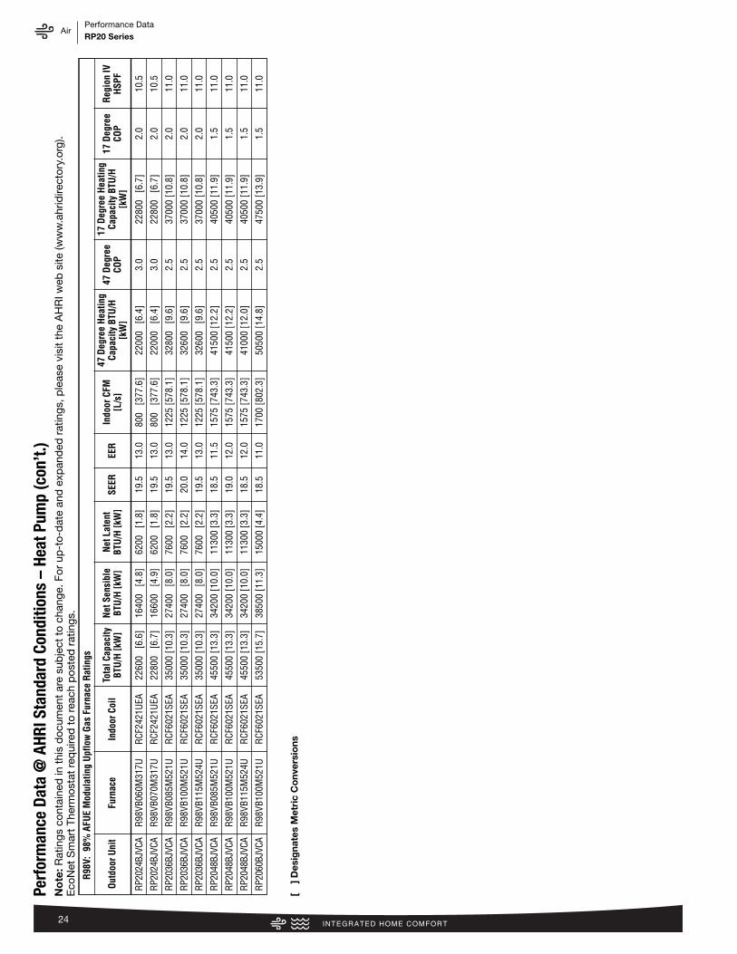
AirPerformance DataRP20 Series
24
Perf
orm
ance
Dat
a @
AHR
I Sta
ndar
d Co
nditi
ons
–He
at P
ump
(con
’t.)
R98
V: 9
8% A
FUE
Mod
ulat
ing
Upf
low
Gas
Fur
nace
Rat
ings
Out
door
Uni
tFu
rnac
eIn
door
Coi
lTo
tal C
apac
ityBT
U/H
[kW
]N
et S
ensi
ble
BTU
/H [k
W]
Net
Lat
ent
BTU
/H [k
W]
SEER
EER
Indo
or C
FM[L
/s]
47 D
egre
e H
eatin
gCa
paci
ty B
TU/H
[kW
]
47 D
egre
eCO
P
17 D
egre
e H
eatin
gCa
paci
ty B
TU/H
[kW
]
17 D
egre
eCO
PR
egio
n IV
HSP
F
RP20
24BJ
VCA
R98
VB06
0M31
7UR
CF24
21U
EA22
600
[6.6
]16
400
[4.8
]62
00
[1.8
]19
.513
.080
0 [3
77.6
]22
000
[6.4
]3.
022
800
[6.7
]2.
010
.5
RP20
24BJ
VCA
R98
VB07
0M31
7UR
CF24
21U
EA22
800
[6.7
]16
600
[4.9
]62
00
[1.8
]19
.513
.080
0 [3
77.6
]22
000
[6.4
]3.
022
800
[6.7
]2.
010
.5
RP20
36BJ
VCA
R98
VB08
5M52
1UR
CF60
21SE
A35
000
[10.
3]27
400
[8.0
]76
00
[2.2
]19
.513
.012
25 [5
78.1
]32
800
[9.6
]2.
537
000
[10.
8]2.
011
.0
RP20
36BJ
VCA
R98
VB10
0M52
1UR
CF60
21SE
A35
000
[10.
3]27
400
[8.0
]76
00
[2.2
]20
.014
.012
25 [5
78.1
]32
600
[9.6
]2.
537
000
[10.
8]2.
011
.0
RP20
36BJ
VCA
R98
VB11
5M52
4UR
CF60
21SE
A35
000
[10.
3]27
400
[8.0
]76
00
[2.2
]19
.513
.012
25 [5
78.1
]32
600
[9.6
]2.
537
000
[10.
8]2.
011
.0
RP20
48BJ
VCA
R98
VB08
5M52
1UR
CF60
21SE
A45
500
[13.
3]34
200
[10.
0]11
300
[3.3
]18
.511
.515
75 [7
43.3
]41
500
[12.
2]2.
540
500
[11.
9]1.
511
.0
RP20
48BJ
VCA
R98
VB10
0M52
1UR
CF60
21SE
A45
500
[13.
3]34
200
[10.
0]11
300
[3.3
]19
.012
.015
75 [7
43.3
]41
500
[12.
2]2.
540
500
[11.
9]1.
511
.0
RP20
48BJ
VCA
R98
VB11
5M52
4UR
CF60
21SE
A45
500
[13.
3]34
200
[10.
0]11
300
[3.3
]18
.512
.015
75 [7
43.3
]41
000
[12.
0]2.
540
500
[11.
9]1.
511
.0
RP20
60BJ
VCA
R98
VB10
0M52
1UR
CF60
21SE
A53
500
[15.
7]38
500
[11.
3]15
000
[4.4
]18
.511
.017
00 [8
02.3
]50
500
[14.
8]2.
547
500
[13.
9]1.
511
.0
[ ]
Des
igna
tes
Met
ric
Co
nver
sio
ns
No
te: R
atin
gs c
onta
ined
in t
his
doc
umen
t ar
e su
bje
ct t
o ch
ange
. For
up
-to-
dat
e an
d e
xpan
ded
rat
ings
, ple
ase
visi
t th
e A
HR
I web
site
(ww
w.a
hrid
irect
ory.
org)
.E
coN
et S
mar
t Th
erm
osta
t re
qui
red
to
reac
h p
oste
d r
atin
gs.

AirGuide SpecificationsRP20 Series
25
GUIDE SPECIFICATIONS GeneralSystem DescriptionOutdoor-mounted, air-cooled, split-system heat pump unit suit-able for ground or rooftop installation. Unit consists of a hermeticcompressor, composite basepan, an air-cooled coil, propeller-type condenser fan, suction and liquid line service valve, and acontrol box. Unit will discharge supply air upward as shown oncontract drawings. Unit will be used in a refrigeration circuit tomatch up to a coil unit.Quality Assurance— Unit will be rated in accordance with the latest edition of AHRI
Standard 210.— Unit will be certified for capacity and efficiency, and listed in
the latest AHRI directory.— Unit construction will comply with latest edition of ANSI/
ASHRAE and with NEC.— Unit will be constructed in accordance with UL standards and
will carry the UL label of approval. Unit will have c-UL-usapproval.
— Unit cabinet will be capable of withstanding ASTM B117 1000-hr salt spray test.
— Air-cooled condenser coils will be leak tested at 150 psig andpressure tested at 550 psig.
— Unit constructed in ISO9001 approved facility. Delivery, Storage, and Handling— Unit will be shipped as single package only and is stored and
handled per unit manufacturer’s recommendations.Warranty (for inclusion by specifying engineer) — U.S. andCanada only.
ProductsEquipmentFactory assembled, single piece, air-cooled heat pump unit. Con-tained within the unit enclosure is all factory wiring, piping, con-trols, compressor, refrigerant charge R-410A, and special fea-tures required prior to field start-up.Unit Cabinet— Unit cabinet will be constructed of galvanized steel, bonder-
ized, and coated with a powder coat paint.— All units constructed with louver coil protection and corner post.
Louver can be removed by removing one fastener per louverpanel.
AIR-COOLED, SPLIT-SYSTEM HEAT PUMPRP202 TO 5 NOMINAL TONSFans— Condenser fan will be direct-drive propeller type, discharging
air upward.— Condenser fan motors will be totally enclosed, 1-phase type
with class B insulation and permanently lubricated bearings.Shafts will be corrosion resistant.
— Fan blades will be statically and dynamically balanced.— Condenser fan openings will be equipped with coated steel
wire safety guards.Compressor— Compressor will be hermetically sealed.— Compressor will be mounted on rubber vibration isolators.— Compressor will be Copeland fully variable speed.Condenser Coil— Condenser coil will be air cooled.— Coil will be constructed of aluminum fins mechanically bonded
to copper tubes.Refrigeration Components— Refrigeration circuit components will include liquid-line shutoff
valve with sweat connections, vapor-line shutoff valve withsweat connections, system charge of R-410A refrigerant, andcompressor oil.
— Unit will be equipped with filter drier for R-410A refrigerant forfield installation.
Operating Characteristics— The capacity of the unit will meet or exceed _____ Btuh at a
suction temperature of _____ °F/°C. The power consumptionat full load will not exceed _____ kW.
— Combination of the unit and the evaporator or fan coil unit willhave a total net cooling capacity of _____ Btuh or greater atconditions of _____ CFM entering air temperature at the evap-orator at _____ °F/°C wet bulb and _____ °F/°C dry bulb, andair entering the unit at _____ °F/°C.
— The system will have a SEER of _____ Btuh/watt or greater atDOE conditions.
Electrical Requirements— Nominal unit electrical characteristics will be _____ v, single
phase, 60 hz. The unit will be capable of satisfactory operationwithin voltage limits of _____ v to _____ v.
— Nominal unit electrical characteristics will be _____ v, threephase, 60 hz. The unit will be capable of satisfactory operationwithin voltage limits of _____ v to _____ v.
— Unit electrical power will be single point connection. — Control circuit will be 24v.Special Features— Refer to section of this literature identifying accessories and
descriptions for specific features and available enhancements.
AirLimited WarrantyRP20 Series
26
GENERAL TERMS OF LIMITED WARRANTY*Rheem will furnish a replacement for any part of this productwhich fails in normal use and service within the applicableperiod stated, in accordance with the terms of the limited warranty.*For complete details of the Limited and Conditional Warranties, includingapplicable terms and conditions, contact your local contractor or theManufacturer for a copy of the product warranty certificate.
Conditional Unit Replacement(Registration Required) ...............................Ten (10) Years
Parts ............................................................Ten (10) Years

AirNotesRA20 Series
27

The new degree of comfort.™
Rheem Heating, Cooling & Water Heating • P.O. Box 17010 Fort Smith, Arkansas 72917 • www.rheem.com
In keeping with its policy of continuous progress and product improvement, Rheem reserves the right to make changes without notice.
PRINTED IN U.S.A. 8/18 QG FORM NO. P11-811 REV. 5
Rheem Canada Ltd./Ltée • 125 Edgeware Road, Unit 1Brampton, Ontario • L6Y 0P5