Embed Size (px)
Citation preview

Application Note
R01AN5108ED0100 Rev.1.00 Page 1 of 58
Jan.22.20
RH850/U2A
CAN-FD Frame-Routing Autonomous Gateway
Introduction
The RS-CANFD CAN controller in version V4, as included in the RH850/U2x product series, is able to support implicit (autonomous) frame-level routing. In combination with its DMA capabilities and the SDMAC unit within these products, the routing can be expanded even beyond the CAN controller unit borders. In products with more than one RS-CANFD unit, up to 16 CAN channels can be included in the routing (with some limitations). This kind of gateway application does not require any support by CPU computing power, except for error situations. In this application note, a system with 4 channels on each of two RS-CANFD units is described.
As RS-CANFD V4 also supports gateway and DMA operation with transmit queues, the frame-level routing of a gateway can be realized including the often demanded “Most Priority First Out” (MPFO) principle.
Note that signal level gateway routing still requires CPU operation and support.
Target Device
RH850/U2A series products or newer, where RS-CANFD V4 is implemented. Not all products may support all channels. Please refer to your product documentation for details.
Conventions
Within register descriptions, the prefix “RSCFDnCFD” (as mentioned in the user’s manual) is omitted for better readability.
References
[1] User’s Manual of RH850/U2A, R01UH0864EJ [2] RS-CANFD driver set package, available upon request separately [3] Application Note “CAN Usage”, R01AN2535ED, contains API description of RS-CANFD driver set.

RH850/U2A CAN Gateway CAN-FD Frame-Routing Autonomous Gateway
R01AN5108ED0100 Rev.1.00 Page 2 of 58
Jan.22.20
Contents
1. Overview and Features ............................................................................................................ 3
1.1 Features and Limitations .................................................................................................................... 3
1.2 Resources ......................................................................................................................................... 4
2. The Internal Gateway of RS-CANFD ....................................................................................... 5
2.1 Global Configuration .......................................................................................................................... 5
2.1.1 Register Setting Details .................................................................................................................... 6
2.2 Channel Configuration ....................................................................................................................... 7
2.2.1 Register Setting Details .................................................................................................................... 8
2.3 Reception Rules............................................................................................................................... 12
2.3.1 Register Setting Details .................................................................................................................. 12
2.4 Reception Resource (RX-FIFO) Configuration .................................................................................. 14
2.4.1 Register Setting Details .................................................................................................................. 14
2.5 Transmission Resource (TX-Queue) Configuration ........................................................................... 15
2.5.1 Register Setting Details .................................................................................................................. 16
3. The Unit Gateway of SDMAC ................................................................................................ 17
3.1 SDMAC Configuration and Operation ............................................................................................... 18
3.1.1 Register Setting Details .................................................................................................................. 18
3.1.2 Descriptor Initialization ................................................................................................................... 20
3.1.3 Peripheral and RAM Guards in U2A ............................................................................................... 22
4. Using the Application Driver Set of RH850/U2A ..................................................................... 23
4.1 Configuration of RS-CANFD ............................................................................................................. 23
4.2 Configuration of SDMAC .................................................................................................................. 23
4.3 Gateway Initialization and Operation ................................................................................................ 24
5. Source Code of Application ................................................................................................... 25
5.1 RS-CANFD Configuration Settings (rscfd_s.h) .................................................................................. 25
5.2 SDMAC Configuration and Global Settings (Multi_Gateway_Test.h) ................................................. 34
5.3 Gateway Application (Multi_Gateway_Test.c) ................................................................................... 36
Revision History ............................................................................................................................ 58

RH850/U2A CAN Gateway CAN-FD Frame-Routing Autonomous Gateway
R01AN5108ED0100 Rev.1.00 Page 3 of 58
Jan.22.20
1. Overview and Features
Within the RH850/U2A product, a frame-level autonomous CAN-FD routing gateway looks like this:
Figure 1: Overview
Within a RS-CANFD unit, the (internal) gateway functionality is used to perform frame-level routing. Among the units, the SDMAC (DMA) unit is used to transfer CAN-FD frames from a receive FIFO (RX-FIFO) of one unit one transmit queues of each channel of another RS-CANFD unit.
In our application example configuration, the gateway configuration is such, that all frames arriving at one channel shall be transferred to all other channels of all units, as shown in figure 1. However, the arriving frame is not copied to the arrival channel itself.
Also, in the example configuration, only even numbered channels are used. The odd numbered channels are used to form a CAN bus with the associated even channels (01, 23 etc.). This avoids the necessity to have acknowledging on all channels, and a monitoring tool can be plugged in randomly.
The application is based on the RS-CANFD V4 application driver, which is described in application note “CAN Usage”, Renesas document R01AN2535.
1.1 Features and Limitations
The following can be performed by the autonomous CAN-FD gateway application:
• Specific routing of dedicated IDs only (not routing all frames)
• Conversion of bit rate and bit timing (each channel may have its individual setting)
• Conversion of classical CAN of a channel into CAN-FD on another channel
• Conversion of CAN-FD of a channel into classical CAN on another channel with limitations:
o Limitation of frame length to 8 bytes
o Limitation of bus speed

RH850/U2A CAN Gateway CAN-FD Frame-Routing Autonomous Gateway
R01AN5108ED0100 Rev.1.00 Page 4 of 58
Jan.22.20
The following limitations apply for the autonomous CAN-FD gateway application:
• When transferring to a slower bit rate channel, or a channel which has slow transmission due to a full bus, a transmit queue overflow may occur, which must be managed by software.
• The maximum number of destinations for one message is 8. Therefore, when using more than 8 channels, a set of 8 channels must be chosen for a dedicated ID or all messages to be the destinations. Nevertheless, destinations may be different for different groups of IDs.
• When transferring messages to the same transmit queue for several source channels, the transmit queue may overflow, even though the MPFO principle is still maintained.
1.2 Resources
The following resources are going to be used. For the example application, values of the configuration are given.
• Channels: All channels can be used. In the example, only even channels are used for the gateway, odd channels are used as acknowledge generators to allow a flexible attachment of a probing tool with limited number of channels.
• Reception Rules: Individual rules can be set for up 384 IDs per channel (1536 rules in total for the 8-channel RS-CANFD V4). In the example, only one rule is used per channel to perform the frame routing. This rule declares that all IDs are routed to all even channels (except the local one) and to one dedicated RX-FIFO unit, which is supporting the DMA transfer to the other RS-CANFD unit. In addition, in the example one additional rule per channel is reserved for the reception of a special message into an extra RX-FIFO, which is the “exit” condition of the application.
• Receive FIFO (RX-FIFO) Units: One RX-FIFO is required for each source channel in the receiving RS-CANFD unit. In the example, 4 RX-FIFO units are used to serve the even channels of the receiving RS-CANFD unit. As every RX-FIFO is handled individually by a SDMAC channel, its size can be set to a minimum, which is 4 entries. After every reception, the assigned SDMAC channel will immediately fetch the received frame and transfer it. In addition, in the example one additional RX-FIFO is reserved for the reception of a special message, which is the “exit” condition of the application.
• Transmit Queues: Every channel has 4 transmit queues. The fourth transmit queue is needed for DMA usage when transferring frames from the other unit. All other queues (0…2) are used for the internal gateway of the RS-CANFD unit. In the example, four channels per unit are used in the gateway, thus three transmit queues are used for the internal gateway in a one-to-one assignment. This balances best the number of messages within the queues and prevents best any overflow conditions. The used queue size is set to its maximum, which is 16, if all queues are used equally. When using more than 4 channels per unit, the use of the first three transmit queues must be shared among several channels.
• Unused resources:
o Transmit FIFO: Not used, as it does not support the MPFO principle.
o Receive Message Boxes: Not used for the gateway but can be used in addition for any further software-based routing purposes (like signal routing).
o Transmit Message Boxes: Not used for the gateway. In case that software-based transmissions are required (like for signal routing), some transmit message boxes (at least two) should be derived from the transmit queues by reducing their size.

RH850/U2A CAN Gateway CAN-FD Frame-Routing Autonomous Gateway
R01AN5108ED0100 Rev.1.00 Page 5 of 58
Jan.22.20
2. The Internal Gateway of RS-CANFD
The internal gateway configuration within one RS-CANFD unit is looking like this:
Figure 2: Internal Gateway of RS-CANFD
All incoming messages of a channel are routed to these destinations (4 in total for the example):
• One RX-FIFO unit, for triggering the SDMAC channel to transfer to the other unit
• One of the first three transmit queues of three channels (all channels except the local one).
While the RX-FIFO unit is storing the message with SDMAC triggering for a transfer to another RS-CANFD unit, the transmit queues are directly triggering the transmission of the corresponding channels. This forwarding from reception into a transmit queue is the essential part of the internal gateway of RS-CANFD.
Not shown in the figure is the additional rule check for the program exit. If an extended-ID message arrives on any channel, this message is not forwarded to the internal gateway, but to a separate RX-FIFO in order to trigger an interrupt. This CPU interrupt then is used to exit the application.
2.1 Global Configuration
For the global settings of the RS-CANFD unit, the following settings are considered:
• Mirror Mode (CFDGCFG.MME) For internal gateway operation, it is not mandatory to set this flag. MME allows the copying of own sent messages into a dedicated storage according to special filter rules. Here, it is an option.
• Global Error Signalling (CFDGCTR.QMEIE and CFDGCTR.MEIE) CPU should be able to recognize lost messages of the internal gateway function, either when using the RX-FIFO (MEIE) or the transmit queue forwarding (QMEIE). Therefore, these error interrupts should be enabled and handled accordingly (restarting the affected FIFO units or queues).

RH850/U2A CAN Gateway CAN-FD Frame-Routing Autonomous Gateway
R01AN5108ED0100 Rev.1.00 Page 6 of 58
Jan.22.20
• Activation of global resources (CFDRMDB, RNC, CFDRFCCx, CFDCDTCT, CFDCDTTCT) The RX-FIFO Units shall be configured to be capable to receive all sizes of messages. Additional message boxes can be added optionally. A minimum of two reception rules per channel are needed (internal gateway and exit condition). DMA operation modes of RX-FIFO and transmit queues must be enabled for the RX-FIFO units and the third transmit queue of each channel.
2.1.1 Register Setting Details
Register Bit Driver Setting Value Comment
GCFG TPRI RSCFD_TXPRIO_ID 0 When sending, choose transmit priority by ID.
DCE RSCFD_DLCCHECK_DISABLE 0 No DLC check filtering performed.
DRE RSCFD_DLCREPL_DISABLE 0 No DLC replacement enabled.
MME RSCFD_MIRROR_ENABLE 1 Mirror mode active (optional)
DCS RSCFD_CLOCK_SYS 0 Internal clock used (required for CAN-FD operation)
CMPOC RSCFD_PLOVF_TRUNCATE 1 Longer frames are truncated, but accepted (optional)
TSP 0 → Fastest timestamp clock
TSSS RSCFD_CLOCK_TSBIT 1 Bit time clock of channel 0 used for timestamps
TSBTCS RSCFD_CHANNEL0 0
ITRCP RSCFD_CLOCK_FIFO_OFF 0 No interval time for FIFO transmissions (not relevant).
GCTR GMDC RSCFD_OPMODE_KEEP → Operation mode is set by the driver, and not
configured beforehand.
GSLPR RSCFD_SLEEP_DISABLE 0 Sleep mode disabled.
… IE RSCFD_GINT_MSGLOST | RSCFD_GINT_GWTXQLOST
→ Global interrupts selected are: Loss of messages, transmit queue message loss.
TSRST RSCFD_TIMESTAMP_KEEP 0 Timestamp counter continues / is not cleared.
GFDCFG RPED RSCFD_PROTEXCEVENT_EN 0 Protocol exception event handling is enabled.
TSCCFG RSCFD_TSCAPTURE_SOF 0 Timestamps are captured at SOF (start of frame).
RMNB NRXMB 1 → One standard receive buffer (optional, not used).
RMPLS RSCFD_BUFDL_64 7 Full CAN-FD payload length to fit in this buffer.
CDTCT RFDMAE RSCFD_DMA_RXF0 |
RSCFD_DMA_RXF1 |
RSCFD_DMA_RXF2 | RSCFD_DMA_RXF3
15 Four RX-FIFO units are used for DMA transfers of SMDAC channels (4 channels per unit for the
internal gateway).
CFDMAE RSCFD_DMA_ALLOFF 0 No DMA association with multi-purpose FIFO units in receive direction.
CDTTCT TQ0DMAE RSCFD_DMA_ALLOFF 0 No DMA association with transmit queues #0.
TQ3DMAE ( 1 << RSCFD_CHANNEL0 ) | ( 1 << RSCFD_CHANNEL2 ) | ( 1 << RSCFD_CHANNEL4 ) | ( 1 << RSCFD_CHANNEL6 )
85 From each included channel of the internal gateway, its fourth transmit queue (#3) is associated with the DMA of a SDMAC channel.
CFDMAE RSCFD_DMA_ALLOFF 0 No DMA association with multi-purpose FIFO units in transmit direction.
GFCMC FLXC RSCFD_FLEXCAN_OFF 0 FlexCAN functionality not used.
GFTBAC FLXMBx RSCFD_FLEXBUF_NONE 0 No flexible transmit buffer assignment (standard
configuration of each channel).

RH850/U2A CAN Gateway CAN-FD Frame-Routing Autonomous Gateway
R01AN5108ED0100 Rev.1.00 Page 7 of 58
Jan.22.20
2.2 Channel Configuration
As an example configuration in this application note, the four even numbered channels of each RS-CANFD unit are actively included in the hardware gateway. The other four (uneven numbered) channels are used as acknowledging channels, so that every bus between an even and an odd channel (i.e., 01, 23 etc.) does not require an additional node to work. Acknowledging (odd) channels are not receiving any message; they are simply acknowledging each message on the bus to be valid.
The four even numbered channels are having the following special configuration:
• Channel Error Signalling (CFDCmCTR.TDCVFIE, -.BLIE, -.BOEIE) These channel errors require special attention for software; in case of transmitter delay compensation errors, bus-off or bus-lock situations a restart of the channel may be required. Bus-off recovery is set to its standard (ISO rule compatible), this also means that recovery happens automatically.
• Transmit Queues (CFDTXQCCxm) These are all enabled; with queues 0…2 set in gateway operation mode, queue 3 in normal mode. Overwrite mode is disabled for all queues, so that the gateway must not lose any message, even if it should get repeated before an old one was sent out. The interrupt of the queues is enabled for every message (but not used by software). The depth is set equally for all queues to be half of the maximum size. This setting would take all transmit buffers in use with a queue. Entry windows (buffers) of the queues are the buffers 0 (queue 0), 31 (queue 1), 32 (queue 2) and 63 (queue 3). Payload size of the transmit queues does not need to be adjusted; in RS-CANFD V4 it is always covering the maximum payload size of 64 data bytes.
• Bit rate In order to show the performance, the CAN-FD bitrate is set to 500 kbit/s (arbitration) and 4 Mbit/s (data) speed. Transmitter compensation is activated and set such, that the secondary sampling point has the same position in the transmitted and feedback bit, as in the reception bit.
• Other channel resources (TX-RX)-FIFOs assigned to channels and the transmit history lists are not used.
• Acknowledging (odd) channels These channels do not have any resources activated (no transmit queues, no error signalling), as they are not transmitting frames. Bus-off recovery settings are set to ISO, even though not required either.

RH850/U2A CAN Gateway CAN-FD Frame-Routing Autonomous Gateway
R01AN5108ED0100 Rev.1.00 Page 8 of 58
Jan.22.20
2.2.1 Register Setting Details
2.2.1.1 Channels used in the Internal Gateway (even channels)
“m” represents the channel number.
Register Bit Driver Setting Value Comment
CmNCFG NBRP 0 Setting for 500 kbit/s with sampling point at
80%, communication clock speed of 80 MHz. NSJW 31
NTSEG1 126
NTSEG2 31
CmDCFG DBRP 0 Setting for 4 Mbit/s with sampling point at
80%,
communication clock speed of 80 MHz. DTSEG1 14
DTSEG2 3
DSJW 3
CmCTR CHMDC RSCFD_OPMODE_KEEP → Operation mode is set by the driver, and not
configured beforehand.
CSLPR RSCFD_SLEEP_DISABLE 0 Sleep mode disabled.
RTBO 0 → Not for configuration. To be set by driver during operation, if requested.
… IE RSCFD_CINT_TDCVIOL | RSCFD_CINT_BUSLOCK |
RSCFD_CINT_BUSOFF
→ Bus related problems to be reported, which require CPU intervention: TDC violation, Bus Lock, Bus Off. All other errors can be handled
and recovered automatically by the CAN transfer layer.
BOM RSCFD_BOM_ISO 0 ISO 11898-1 compliant automatic bus-off recovery.
ERRD 0 → Show only first error code at an incident.
CTME 0 → No test mode used.
CTMS RSCFD_TEST_BASIC 0 Not relevant, as no test mode is used.
CRCT 0 → No CRC error test mode.
ROM RSCFD_RESTRICTED_DIS 0 No restricted operation mode (full transmitting and acknowledging enabled).
CmFDCTR EOCCLR RSCFD_OCC_KEEP 0 Successful occurrence counter not cleared.
SOCCLR RSCFD_OCC_KEEP 0 Error occurrence counter not cleared.
CmFDCFG EOCCFG RSCFD_EOC_ALLTXRX 0 Error occurrence counter counts all
transmitter and receiver CAN frames.
TDCOC RSCFD_TDC_MEASOFFSET 0 Enabled the automatic offset measurement of TDC.
TDCE RSCFD_TDC_ENABLE 1 Transmitter delay compensation active.
ESIC RSCFD_ESI_BYNODE 0 ESI flag of frame is driven by the node only.
TDCO 15 → Transmitter delay compensation offset, to achieve a 80% secondary sampling point at 4 Mbit/s by counting 16 clocks of the 80 MHz
clock.
GWEN RSCFD_MULTIGW_DISABLE 0 No Multi-Gateway mode (no conversion of classical to CAN-FD frames or vice versa).
GWFDF RSCFD_FDF_FD 1 Not relevant, as Multi-Gateway mode is disabled.
GWBRS RSCFD_BRS_SWITCH 1
FDOE RSCFD_FDMIXED 0 Mixed operation of classical and CAN-FD frames.

RH850/U2A CAN Gateway CAN-FD Frame-Routing Autonomous Gateway
R01AN5108ED0100 Rev.1.00 Page 9 of 58
Jan.22.20
REFE RSCFD_RXEDGEFILTER_ON 1 RX edge filter is enabled (prevents wrong synchronization).
CLOE RSCFD_FDMIXED 0 Mixed operation of classical and CAN-FD frames.
TMIECy TMIE 0 → No interrupts from transmit buffers.
THLCCm THLE RSCFD_THL_OFF 0 The transmit history list is disabled.
Settings apart from THLE are not relevant.
By using the THL, software can verify the gateway activity (beyond this application note).
THLIE 0 →
THLIM RSCFD_THL_INT_ONLEVEL 0
THLDTE RSCFD_THL_ENTRY_QUEUED 0
THLDGE RSCFD_THL_GWENTRY_OFF 0
CFCCk CFE 0 → The multi-purpose FIFO units are disabled.
Settings apart from CFE are not relevant and are set to their default state. CFRXIE 0 →
CFTXIE 0 →
CFPLS RSCFD_FIFODL_8 0
CFM RSCFD_FIFO_MODE_RX 0
CFITSS RSCFD_FIFO_IT_REFCLK 0
CFITR RSCFD_FIFO_IT_REFCLK1 0
CFIM RSCFD_FIFO_INT_ONLEVEL 0
CFIGCV RSCFD_FIFO_ILEVEL_1D8 0
CFTML 0 →
CFDC RSCFD_FIFO_DEPTH_0 0
CFITT 0 →
CFCCEk CFFIE 0 →
CFOFRXIE 0 →
CFOFTXIE 0 →
CFMOWN RSCFD_COM_FIFO_DSCMODE 0
CFBMIE 0 →

RH850/U2A CAN Gateway CAN-FD Frame-Routing Autonomous Gateway
R01AN5108ED0100 Rev.1.00 Page 10 of 58
Jan.22.20
2.2.1.2 Channels not used in the Internal Gateway (odd channels, bus acknowledging only)
“m” represents the channel number.
Register Bit Driver Setting Value Comment
CmNCFG NBRP 0 Setting for 500 kbit/s with sampling point at
80%, communication clock speed of 80 MHz. NSJW 31
NTSEG1 126
NTSEG2 31
CmDCFG DBRP 0 Setting for 4 Mbit/s with sampling point at
80%,
communication clock speed of 80 MHz. DTSEG1 14
DTSEG2 3
DSJW 3
CmCTR CHMDC RSCFD_OPMODE_KEEP → Operation mode is set by the driver, and not
configured beforehand.
CSLPR RSCFD_SLEEP_DISABLE 0 Sleep mode disabled.
RTBO 0 → Not for configuration. To be set by driver during operation, if requested.
… IE RSCFD_CINT_OFF 0 No interrupts.
BOM RSCFD_BOM_ISO 0 ISO 11898-1 compliant automatic bus-off recovery.
ERRD 0 → Show only first error code at an incident.
CTME 0 → No test mode used.
CTMS RSCFD_TEST_BASIC 0 Not relevant, as no test mode is used.
CRCT 0 → No CRC error test mode.
ROM RSCFD_RESTRICTED_DIS 0 No restricted operation mode (full transmitting and acknowledging enabled).
CmFDCTR EOCCLR RSCFD_OCC_KEEP 0 Successful occurrence counter not cleared.
SOCCLR RSCFD_OCC_KEEP 0 Error occurrence counter not cleared.
CmFDCFG EOCCFG RSCFD_EOC_ALLTXRX 0 Error occurrence counter counts all
transmitter and receiver CAN frames.
TDCOC RSCFD_TDC_MEASOFFSET 0 Enabled the automatic offset measurement of TDC.
TDCE RSCFD_TDC_ENABLE 1 Transmitter delay compensation active.
ESIC RSCFD_ESI_BYNODE 0 ESI flag of frame is driven by the node only.
TDCO 15 → Transmitter delay compensation offset, to achieve a 80% secondary sampling point at 4 Mbit/s by counting 16 clocks of the 80 MHz clock.
GWEN RSCFD_MULTIGW_DISABLE 0 No Multi-Gateway mode (no conversion of classical to CAN-FD frames or vice versa).
GWFDF RSCFD_FDF_FD 1 Not relevant, as Multi-Gateway mode is disabled.
GWBRS RSCFD_BRS_SWITCH 1
FDOE RSCFD_FDMIXED 0 Mixed operation of classical and CAN-FD frames.
REFE RSCFD_RXEDGEFILTER_ON 1 RX edge filter is enabled (prevents wrong synchronization).
CLOE RSCFD_FDMIXED 0 Mixed operation of classical and CAN-FD frames.

RH850/U2A CAN Gateway CAN-FD Frame-Routing Autonomous Gateway
R01AN5108ED0100 Rev.1.00 Page 11 of 58
Jan.22.20
TMIECy TMIE 0 → No interrupts from transmit buffers.
TXQCC[0:3]m TXQE RSCFD_TXQ_OFF 0 The transmit queues are disabled.
Settings apart from TXQE are not relevant. TXQGWE RSCFD_TXQ_GW_DISABLE 0
TXQOWE RSCFD_TXQ_OWR_DISABLE 0
TXQTXIE 0 →
TXQIM RSCFD_TXQ_INT_ONLAST 0
TXQDC RSCFD_TXQ_OFF 0
TXQFIE 0 →
TXQOFRXIE 0 →
TXQOFTXIE 0 →
THLCCm THLE RSCFD_THL_OFF 0 The transmit history list is disabled.
Settings apart from THLE are not relevant.
By using the THL, software can verify the gateway activity (beyond this application
note).
THLIE 0 →
THLIM RSCFD_THL_INT_ONLEVEL 0
THLDTE RSCFD_THL_ENTRY_QUEUED 0
THLDGE RSCFD_THL_GWENTRY_OFF 0
CFCCk CFE 0 → The multi-purpose FIFO units are disabled.
Settings apart from CFE are not relevant and are set to their default state. CFRXIE 0 →
CFTXIE 0 →
CFPLS RSCFD_FIFODL_8 0
CFM RSCFD_FIFO_MODE_RX 0
CFITSS RSCFD_FIFO_IT_REFCLK 0
CFITR RSCFD_FIFO_IT_REFCLK1 0
CFIM RSCFD_FIFO_INT_ONLEVEL 0
CFIGCV RSCFD_FIFO_ILEVEL_1D8 0
CFTML 0 →
CFDC RSCFD_FIFO_DEPTH_0 0
CFITT 0 →
CFCCEk CFFIE 0 →
CFOFRXIE 0 →
CFOFTXIE 0 →
CFMOWN RSCFD_COM_FIFO_DSCMODE 0
CFBMIE 0 →

RH850/U2A CAN Gateway CAN-FD Frame-Routing Autonomous Gateway
R01AN5108ED0100 Rev.1.00 Page 12 of 58
Jan.22.20
2.3 Reception Rules
To support the gateway functionality, every included channel (all even channels in the example) gets at least one reception rule. This reception rule must perform the following actions:
• Filter the messages which must be processed for the gateway.
• Set the gateway target mode to “transmit queue” instead of “transmit FIFO”.
• Define a label for the filtered and processed messages to identify them when monitoring the gateway operation.
• As destination targets, set the dedicated RX-FIFO unit for the unit gateway (buffer for the SDMAC) and all transmit queues of the other channels within the internal gateway. In the example, this yields 7 destinations.
• When using more than 4 channels in the gateway per unit, the maximum number of destinations must be taken into consideration, which is 8. In this case, not all frames can be routed to all destinations at a time with this approach, if a local reception of the gateway is desired, too. A selective routing to dedicated destinations, depending on the ID of the frames may be required. The example with 4 channels already is using 4 destinations, because all received frames shall be copied to all other channels, except the receiving channel.
2.3.1 Register Setting Details
Register Bit Driver Setting Value Comment
GAFLCFG RNC { 2, 0, 2, 0, 2, 0, 2, 0 } → The GAFLCFG register set is written in detail by
the driver set [2]. All even channels get two rules, the odd channels (not in gateway) get no rules.
GAFLIDx GAFLID 0 → The ID value is not relevant, because the
corresponding mask in GAFLM is fully open.
GAFLLB RSCFD_AFL_RXENTRY 0 Rule for reception (not for mirror mode).
GAFLRTR RSCFD_FRAME_DATA 0 Rule for data frames.
GAFLIDE RSCFD_ID_STD 0 Rule for standard ID frames. The gateway operates with standard ID frames only in this example. To allow extended ID frames, the corresponding mask bit GAFLIDEM in GAFLM
needs to be cleared.
GAFLMx GAFLIDM RSCFD_MASK_IDDONTCARE 0 All ID of frames are accepted.
GAFLIFL1 RSCFD_AFL_IFL1_MASK( z1 ) → z1 can be specified to monitor the reception within the RX-FIFO units by software (optional).
GAFLRTRM RSCFD_MASK_FILTER 1 Only data frames are accepted.
GAFLIDEM RSCFD_MASK_FILTER 1 Only standard ID frames are accepted.
GAFLP0x GAFLDLC RSCFD_DLCCHECK_DISABLE 0 All lengths of frames are accepted.
GAFLSRD0 RSCFD_AFL_SRD_TOTXQ 1 The routing target is transmit queue 0.
GAFLSRD1 RSCFD_AFL_SRD_TOTXQ 1 The routing target is transmit queue 1.
GAFLSRD2 RSCFD_AFL_SRD_TOTXQ 1 The routing target is transmit queue 2.
GAFLIFL0 RSCFD_AFL_IFL1_MASK( z2 ) → z2 can be specified to monitor the reception within the RX-FIFO units by software (optional).
GAFLRMDP 0 → Standard receive buffer 0 is activated as reception target (optional, for debug or monitoring purposes)
GAFLRMV RSCFD_SET 1
GAFLPTR 0 → Not relevant but can be specified to monitor the reception within the RX-FIFO units by software (optional).

RH850/U2A CAN Gateway CAN-FD Frame-Routing Autonomous Gateway
R01AN5108ED0100 Rev.1.00 Page 13 of 58
Jan.22.20
GAFLP1x GAFLFDP Depends on channel → See details below.
The target setting within GAFLP1x is different for each of the operating channels of the internal gateway (0, 2, 4, 6): in this register, the destinations (RX-FIFO units and transmit queues of other channels) are specified.
The following scheme is used for the channels of the internal gateway, with IFL = {z1, z2} of the table above:
• Channel 0: receive into RXFIFO0, and into Channel 2,4,6 TX Queues 0, 0, 0; IFL = 00
• Channel 2: receive into RXFIFO1, and into Channel 0,4,6 TX Queues 0, 1, 1; IFL = 01
• Channel 4: receive into RXFIFO2, and into Channel 0,2,6 TX Queues 1, 1, 2; IFL = 10
• Channel 6: receive into RXFIFO3, and into Channel 0,2,4 TX Queues 2, 2, 2 ; IFL = 11

RH850/U2A CAN Gateway CAN-FD Frame-Routing Autonomous Gateway
R01AN5108ED0100 Rev.1.00 Page 14 of 58
Jan.22.20
2.4 Reception Resource (RX-FIFO) Configuration
The RX-FIFO units are the buffers for reception of all messages, which shall be transferred from one unit of RS-CANFD to another. In this example, for each destination transmit queue of the other RS-CANFD unit, one RX-FIFO is used on the local unit. That means, the duplication of a frame from reception into several destinations of another RS-CANFD unit is performed by storing the frame in several RX-FIFO units at a time. Also, this means that a RX-FIFO is reception destination of all receiving (even) channels of the internal gateway within a RS-CANFD unit.
The RX-FIFO units shall be configured such, that they can hold the full length of any frame in worst case (maximum length of CAN-FD). The interrupt trigger of the RX-FIFO shall be set to an interrupt on every reception, even though this interrupt will not be handled by software but is the SDMAC trigger instead.
The RX-FIFO depth should be two frames per channel at minimum, because the transfer by the SDMAC takes time, while another frame may arrive.
2.4.1 Register Setting Details
Register Bit Driver Setting Value Comment
RFCC[0:3] RFE 0 → The RX-FIFO is enabled by the driver set [2] at a
later state.
RFIE 0 → Interrupt of the RX-FIFO is not required for its gateway and DMA operation.
RFPLS RSCFD_FIFODL_64 7 Full CAN-FD payload length to fit in this FIFO.
RFDC RSCFD_FIFO_DEPTH_4 1 Maximum size to avoid overflow issues.
RFIM RSCFD_FIFO_INT_ONEVERY 1 As interrupt is disabled, this is not relevant.
RFIGCV RSCFD_FIFO_ILEVEL_1D8 0
RFCC[4] RFE 0 → The RX-FIFO is enabled by the driver set [2] at a
later state.
RFIE 1 → Interrupt used as an exit condition for the application.
RFPLS RSCFD_FIFODL_64 7 Full CAN-FD payload length to fit in this FIFO.
RFDC RSCFD_FIFO_DEPTH_4 1 Minimum size for this FIFO, it has to hold one message only, which is the exit condition.
RFIM RSCFD_FIFO_INT_ONEVERY 1 Every received message causes an interrupt.
RFIGCV RSCFD_FIFO_ILEVEL_1D8 0 Not relevant, as the FIFO interrupt is on every message.
RFCC [others]
RFE 0 → The RX-FIFO is not used.
Size is set to its minimum (zero bytes used).
Interrupt settings are not relevant. RFIE 0 →
RFPLS RSCFD_FIFODL_8 0
RFDC RSCFD_FIFO_DEPTH_0 0
RFIM RSCFD_FIFO_INT_ONLEVEL 0
RFIGCV RSCFD_FIFO_ILEVEL_1D8 0

RH850/U2A CAN Gateway CAN-FD Frame-Routing Autonomous Gateway
R01AN5108ED0100 Rev.1.00 Page 15 of 58
Jan.22.20
2.5 Transmission Resource (TX-Queue) Configuration
For every channel, four transmit queues are available. When using 4 channels for the internal gateway, three of the transmit queues are used for the internal gateway, while the 4th queue is left to be used by the unit gateway transfers of the SDMAC.
If more than 4 channels are used in the internal gateway, then every of the first three queues shall be a destination for not one, but several channels of the same unit. This is defined in the reception rules, but beyond this application note.
For a transmit queue which is used in the internal gateway, the following settings shall be applied:
• The gateway function of the transmit queue is enabled. This means, that this queue will not be available for use with software-based transmission.
• The overwrite function of the transmit queue is disabled. In order not to lose frames, even if they were repeated or replaced, the overwrite function cannot be used.
• The interrupt function of the transmit queue is not relevant.
• The size of the queues should be balanced and at a high level. In the example, as all four transmit queues are used, the size of every queue is set to 16, which is a quarter of all available message boxes, and no message boxes are left for transmission beyond the gateway.
For the transmit queue used with SDMAC (the unit gateway transfer), the gateway function must be disabled, because the SDMAC is using them similarly like software, even though the queue is operated in DMA mode, where an explicit push-in is executed automatically. In this example configuration, the overwrite mode was enabled for the fourth (SDMAC assigned) transmit queue. This is for demonstration, to show the effect how the overwrite mode works. For equal treatment of messages and channels, the overwrite mode should be set off for this queue, too.

RH850/U2A CAN Gateway CAN-FD Frame-Routing Autonomous Gateway
R01AN5108ED0100 Rev.1.00 Page 16 of 58
Jan.22.20
2.5.1 Register Setting Details
Register Bit Driver Setting Value Comment
TXQCC[0:2]m TXQE RSCFD_TXQ_ON 1 The transmit queue is activated.
TXQGWE RSCFD_TXQ_GW_ENABLE 1 Transmit queue used in gateway mode (no transmission by software write allowed)
TXQOWE RSCFD_TXQ_OWR_DISABLE 0 No overwrite of existing messages with the same ID (full transparent gateway).
TXQTXIE 0 → No transmit interrupt of the queue.
TXQIM RSCFD_TXQ_INT_ONEVERY 1 Not relevant (interrupt is not activated).
TXQDC RSCFD_TXQ_MAXBUFFERS/2 - 1
15 Quarter of all message buffers assigned to the queue.
TXQFIE 0 → No queue full interrupt enabled. Optional, enabling this can be an enhancement to monitor the gateway load.
TXQOFRXIE 0 → No one-frame interrupts activated.
TXQOFTXIE 0 →
TXQCC3m TXQE RSCFD_TXQ_ON 1 The transmit queue is activated.
TXQGWE RSCFD_TXQ_GW_DISABLE 0 Transmit queue used in normal mode, to be fed by DMA of SDMAC.
TXQOWE RSCFD_TXQ_OWR_ENABLE 1 Overwrite of existing messages with the same ID (optimizing gateway), set here to show the effect.
TXQTXIE 0 → No transmit interrupt of the queue.
TXQIM RSCFD_TXQ_INT_ONEVERY 1 Not relevant (interrupt is not activated).
TXQDC RSCFD_TXQ_MAXBUFFERS/2 - 1
15 Quarter of all message buffers assigned to the queue.
TXQFIE 0 → No queue full interrupt enabled. Optional, enabling this can be an
enhancement to monitor the gateway load.
TXQOFRXIE 0 → No one-frame interrupts activated.
TXQOFTXIE 0 →

RH850/U2A CAN Gateway CAN-FD Frame-Routing Autonomous Gateway
R01AN5108ED0100 Rev.1.00 Page 17 of 58
Jan.22.20
3. The Unit Gateway of SDMAC
The SDMAC is used to transfer messages between two RS-CANFD units. For every RS-CANFD channel of a unit, one SDMAC channel is used to transfer the frames. CAN-FD frames are fetched from a dedicated RX-FIFO of the RS-CANFD source unit and written to the 4th transmit queue of every used channel in the destination RS-CANFD unit.
The task of SDMAC is to duplicate a frame into several destinations.
Consequently, the functional view of the SDMAC channel operation looks like this:
Figure 3: SDMAC Channel Operation
As soon as the RX-FIFO assigned to a receiving channel of a RS-CANFD unit A triggers it, the SDMAC will fetch the frame from the RX-FIFO by reading the DMA access memory area of it. The length of the DMA is set such, that it covers the full RX-FIFO frame length size. This will trigger the RX-FIFO to shift to the next received message, if available.
The final destination of the SDMAC channel are the 4th transmit queues of all channels of the transmitting RS-CANFD unit B. Even though not all bits of control and pointer operation of the RX-FIFO are the same as on the transmit queue, the direct copying works nevertheless, because non-existent bits in the transmit queue destinations are ignored by the RS-CANFD hardware. The size of the access windows of RX-FIFO and transmit queues are identical, and the ordering of information is equal.
To achieve this target, the received frame from the RX-FIFO must be copied multiple times, so that each 4th transmit queue of RS-CANFD unit B will get it. To do this, the SDMAC channel first copies the frame into a RAM location. From there, the multiple copying steps are performed by the next steps, each one to write the frame into a 4th transmit queue of used channels in RS-CANFD unit B.
SDMAC supports descriptor chains, which allow several operations in sequence; in our example in five steps: First to read the RX-FIFO into a RAM location, and subsequent four to copy the frame from the RAM location into the four used channels’ 4th transmit queues.
Note that in this configuration, the RX-FIFO will never be filled with more than one frame, while it is ready to receive a second one from the CAN channel. SDMAC must be able to fetch this frame from the RX-FIFO, until the next frame is reception is completed. Otherwise, the RX-FIFO would trigger another DMA request, while SDMAC is still working with the previous one; and the same would cause a request overflow condition on SDMAC.

RH850/U2A CAN Gateway CAN-FD Frame-Routing Autonomous Gateway
R01AN5108ED0100 Rev.1.00 Page 18 of 58
Jan.22.20
3.1 SDMAC Configuration and Operation
The transfer configuration of SDMAC is set to longwords (4 bytes) as access size for source and destination, with incrementing addresses on both sides, and 19 longwords in total for one block. 19 longwords are the RX-FIFO and transmit queue DMA window size, when the payload length of CAN-FD is set to 64 bytes (maximum).
The hardware trigger source is used, its channel depends on the assigned RX-FIFO of the receiving RS-CANFD unit.
For proper operation, the SDMAC needs to get an assigned SPID, and an opened peripheral guard and RAM guard window assigned to the same. This configuration is made in the peripheral guard hardware, which depends on the target device.
The used descriptor is required to allow a restore of source, destination addresses and the transfer count, after the current transfer was completed. By setting the continuation flag (CF), the descriptor also restores the enabled state of the channel, so that it is ready for the next trigger.
3.1.1 Register Setting Details
The channel configuration is set according to the requirements of the gateway functionality, as follows (“n“ is the channel index of the SDMAC, n = {0…7}):
Register Bit Value Comment
SARn SAR - Not set. Descriptor chain values are used.
DARn DAR - Not set. Descriptor chain values are used.
TSRn TSR 0 This forces the descriptor chain lookup for next execution steps for this event.
TMRn STS SDMAC_TRANSSIZE_4BYTE 2 Longword access for source and destination.
DTS SDMAC_TRANSSIZE_4BYTE 2
SM SDMAC_ADDRESSMODE_INCREMENT 1 Incrementing source and destination addresses
to read the window completely.
DM SDMAC_ADDRESSMODE_INCREMENT 1
TRS SDMAC_REQUESTSOURCE_HARDWARE 1 Trigger the SDMAC channel upon hardware request.
PRI 0 → Default priority of the channel for all.
SLM SDMAC_SLOWSPEED_OFF 0 Normal speed of the SDMAC channel.
CHCRn DE SDMAC_CLEAR → Activated by the SDMAC driver by command.
IE SDMAC_CLEAR 0 No interrupts of the SDMAC channel, as no CPU intervention is desired.
DSIE
CAIE
CAEE

RH850/U2A CAN Gateway CAN-FD Frame-Routing Autonomous Gateway
R01AN5108ED0100 Rev.1.00 Page 19 of 58
Jan.22.20
DPB SDMAC_CLEAR 0 Channel configuration is not immediately pre-
loaded from the descriptor setting, but fetched from the descriptor after event trigger.
DPE SDMAC_SET 1 Descriptor operation is enabled, so that by this
functionality, the SDMAC channel stays active and restores its settings after each transfer.
… AIn GIAI
GOAI
SIAI
SOAI
0 Not used. Scatter- and gather functionality is not needed for this application.
SGCRn → 0
RSn RS 45, 46, 47, 48 (RS-CANFD unit 0 RX-FIFO triggers)
53, 54, 55, 56 (RS-CANFD unit 1 RX-FIFO triggers)
Value depends on the assigned SDMAC channel
number.
DRQI SDMAC_CLEAR 0 No DMA request flag initialization at descriptor
PLE SDMAC_CLEAR 0 No reading access before hardware trigger
FPT SDMAC_CLEAR 0 Not relevant, because preload is disabled by PLE
TL SDMAC_TRLIMIT_BY_STS_TC 0 Transaction size is TC * STS (=longwords)
TC 19 * 5 → 19 longwords to transfer per DMA trigger, but 5 descriptor chain steps to be executed, each one has 19 longword transfers.
BUFCRn ULB SDMAC_BUFFERLIMIT_DEFAULT 128 Default setting.
DPPTRn CF SDMAC_SET 1 Continuous operation.
DIE 0 → No descriptor interrupt.
PTR → Pointer to first descriptor of the assigned chain in descriptor memory of SDMAC. The SDMAC driver provides this pointer when using its API to
enter the first descriptor of a new chain.
DPCRn UPF SDMAC_DESCUPDATEFLAG_SAR | SDMAC_DESCUPDATEFLAG_DAR |
SDMAC_DESCUPDATEFLAG_TSR
Registers SAR, DAR and TSR will get updated by the descriptor execution.
CMn UM SDMAC_CLEAR 0 SDMAC shall operate in supervisor mode.
SPID 1CH The SPID for the peripheral access guard is set.

RH850/U2A CAN Gateway CAN-FD Frame-Routing Autonomous Gateway
R01AN5108ED0100 Rev.1.00 Page 20 of 58
Jan.22.20
3.1.2 Descriptor Initialization
According to the settings of the DPCRn registers, each descriptor of the chain of each channel contains the register values of SARn, DARn and TSRn.
Additionally, each descriptor of SDMAC must contain the DPPTRn register value. The PTR (pointer to descriptor) value is creating the linked list of the descriptor chain, and for the last element in the descriptor chain, PTR is set such, that it points to the first descriptor of the chain. This setting achieves that the descriptor chain is used every time again, as soon as a new trigger from the RX-FIFO of RS-CANFD (the trigger source) happens. At the same time, by using the last descriptor of the chain, the initial values of SARn, DARn and TSRn are restored, so that the subsequent transfer is identical with the previous one. Background of this is, that SARn, DARn and TSRn are changing during the SDMAC channel operation, according to the processing of the DMA transfer (incrementing SARn, and DARn, decrementing TSRn).
First descriptor of the chain of SDMAC channel n = {0…7} and RS-CANFD unit m = {0…1}, m=n/4 (example with 4 channels per unit):
Register Bit Value Comment
SARn SAR &( rscfd_rxfifo_p[ m ]
->buf[ n%4 ].id ) Address of the RX-FIFO buffer n of the receiving
RS-CANFD unit, which is assigned to channel n of the SDMAC unit:
rscfd_rxfifo_p[ RSCAN-FD_Unit_RX ]
->buf[ RX-FIFO# ].id
DARn DAR &GW_FrameBuffer[ 0 ][ n ] Address of the RAM buffer used for this channel.
TSRn TSR 19 * 4 The memory window of the RX-FIFO and the transmit queues is 19 longwords. When using the maximum size of CAN-FD frames, the full
window must be read and written by DMA, in order to shift the RX-FIFO and transmit queues after the DMA access. A longword has 4 bytes.
DPPTRn CF SDMAC_SET 1 Continuous operation.
DIE 0 → No descriptor interrupt.
PTR SDMAC_DESC_CHAIN_NEXTFREE →
Pointer to next descriptor of the chain in descriptor memory of SDMAC. Generated by the SDMAC driver.
Second, third and fourth descriptor of the chain of SDMAC channel n (example with 4 channels per unit):
Register Bit Value Comment
SARn SAR &GW_FrameBuffer[ 0 ][ n ] Address of the RAM buffer used for this channel.
DARn DAR &( rscfd_txmsg_p
[ 1-m ][ 2 * (n%4) ]
->buf[ abs( rscfd_txqentries
[ 1-m ]
[ 2 * (n%4) ]
[ 3 ] ) ].id )
Address of the transmit queue #3 of channel
2*(n%4) of the transmitting RS-CANFD unit, which is assigned to channel n of the SDMAC unit:
rscfd_txmsg_p[RSCAN-FD_Unit_TX ]
[ RSCAN-FD_Channel_TX ]
->buf[ abs( rscfd_txqentries
[ RSCAN-FD_Unit_TX ]
[ RSCAN-FD_Channel_TX ]
[ 3 ] ) ].id
The RS-CANFD driver has a table of the amount
of transmit queue entry windows, which indicates the direction of the queue by its sign. This table is used as reference for the transmit queue entry
buffer number.

RH850/U2A CAN Gateway CAN-FD Frame-Routing Autonomous Gateway
R01AN5108ED0100 Rev.1.00 Page 21 of 58
Jan.22.20
TSRn TSR 19 * 4 The memory window of the RX-FIFO and the
transmit queues is 19 longwords. When using the maximum size of CAN-FD frames, the full window must be read and written by DMA, in
order to shift the RX-FIFO and transmit queues after the DMA access.
DPPTRn CF SDMAC_SET 1 Continuous operation.
DIE 0 → No descriptor interrupt.
PTR SDMAC_DESC_CHAIN_LINKPREVIOUS →
Pointer to next descriptor of the chain in
descriptor memory of SDMAC. Generated by the SDMAC driver.
Last descriptor of chain of SDMAC channel n:
Register Bit Value Comment
SARn SAR &GW_FrameBuffer[ 0 ][ n ] Address of the RAM buffer used for this channel.
DARn DAR &( rscfd_txmsg_p
[ 1-m ][ 2 * (n%4) ]
->buf[ abs( rscfd_txqentries
[ 1-m ]
[ 2 * (n%4) ]
[ 3 ] ) ].id )
Address of the transmit queue #3 of channel 2*(n%4) of the transmitting RS-CANFD unit,
which is assigned to channel n of the SDMAC unit:
rscfd_txmsg_p[RSCAN-FD_Unit_TX ]
[ RSCAN-FD_Channel_TX ]
->buf[ abs( rscfd_txqentries
[ RSCAN-FD_Unit_TX ]
[ RSCAN-FD_Channel_TX ]
[ 3 ] ) ].id
The RS-CANFD driver has a table of the amount of transmit queue entry windows, which indicates
the direction of the queue by its sign. This table is used as reference for the transmit queue entry buffer number.
TSRn TSR 19 * 4 The memory window of the RX-FIFO and the transmit queues is 19 longwords. When using the maximum size of CAN-FD frames, the full
window must be read and written by DMA, in order to shift the RX-FIFO and transmit queues after the DMA access.
DPPTRn CF SDMAC_SET 1 Continuous operation.
DIE 0 → No descriptor interrupt.
PTR SDMAC_DESC_CHAIN_LINKPREVIOUS | SDMAC_DESC_CHAIN_LINKSTART
→
Pointer to first descriptor of the assigned chain in descriptor memory of SDMAC. Generated by the SDMAC driver.

RH850/U2A CAN Gateway CAN-FD Frame-Routing Autonomous Gateway
R01AN5108ED0100 Rev.1.00 Page 22 of 58
Jan.22.20
3.1.3 Peripheral and RAM Guards in U2A
In RH850/U2A, the RS-CANFD peripherals and RAM are protected against the access of the SDMAC channels. Therefore, the corresponding peripheral and RAM guard instances must be opened for read- and write accesses of the SDMAC channels by setting their SPID flag.
If the peripheral guard is not opened, the SDMAC cannot transfer the data (neither reading the RX-FIFO, nor using the RAM, nor writing to the transmit queue) and would stop with addressing errors. Note that even though the addressing error may be indicated at an address which is not the first one to attempt, the access of the first address already is blocked. The reason for this is, that the guard and the associated guard error processing runs on a slower clock than SDMAC and PE units, but nevertheless is effective all time.
See the source code for details on which guard registers settings are required.
RH850/U2A CAN Gateway CAN-FD Frame-Routing Autonomous Gateway
R01AN5108ED0100 Rev.1.00 Page 23 of 58
Jan.22.20
4. Using the Application Driver Set of RH850/U2A
4.1 Configuration of RS-CANFD
By doing the following steps of the RS-CANFD driver set, the CAN controllers are initialized:
1. RSCFD_PortEnable: Enable the ports for the CAN controller channels. Both TX and RX ports are set in direction and associated alternate peripheral function.
2. RSCFD_Stop: Set a global reset to the CAN controller unit. This is required to perform the global reconfiguration, if the CAN controller might have been in use before.
3. RSCFD_SetGlobalConfiguration: Set the global configuration of the CAN controller unit. Most of all, this defines the shared memory setup and general operation settings like global errors.
4. RSCFD_SetGlobalFIFOConfiguration: Settings for the RX-FIFO units used.
5. RSCFD_CreateInterrupt: The RX-FIFO interrupt for application exit and the global error state (like missed messages) are activated.
6. RSCFD_Start: Leave the global reset state, ready to initialize the channels.
7. RSCFD_SetGlobalConfiguration: Second call for the global configuration, while in global operation state. This initializes the DMA operation options of the CAN controller unit.
8. RSCFD_EnableRXFIFO: When in global operation state, the RX-FIFO units can be activated.
9. RSCFD_SetAFLEntry: Specifically for the used even channels, the reception rules for gateway reception and application exit are entered.
4.2 Configuration of SDMAC
Following the global initialization of the RS-CANFD units, the SDMAC channels are initialized in the following steps; using some functions of the SDMAC driver package:
1. Open the peripheral guards The access right for read/write is assigned to the SPID of the SDMAC channels.
2. SDMAC_Reset: Global operation setting (activation) and round-robin mode are set for the SDMAC unit.
3. SDMAC_SetDescriptor: Each channel gets its descriptor to allow continuous operation with identical data processing.
4. SDMAC_HWTriggerChannel: The associated trigger source is selected for the channel, including trigger group selection.
5. SDMAC_ConfigureChannel: The channel is initialized for the data transfers (source and destination, trigger, transaction mode and size).
6. SDMAC_EnableChannel: Activates the SDMAC channel to be ready for a hardware trigger from the RS-CANFD units.

RH850/U2A CAN Gateway CAN-FD Frame-Routing Autonomous Gateway
R01AN5108ED0100 Rev.1.00 Page 24 of 58
Jan.22.20
4.3 Gateway Initialization and Operation
In a final step, the RS-CANFD channels are activated, now that the whole infrastructure of the gateway is ready to handle the receptions and transmissions:
1. RSCFD_SetChannelConfiguration: Channel specific settings are made, like bit rate/timing, interrupt sources (for error handling), transmit queue initialization and CAN-FD specific settings. Even and odd channels get different settings; for example the odd channels would not make use of any transmit queues or error interrupts.
2. RSCFD_Start: The channels are set to operation mode. At this point, the gateway will start operation with the integration phase on the CAN(-FD) bus of the even and odd channels.
After these steps, the gateway is active and does not require further CPU support, apart from error situations. Errors would be reported as interrupts; in this case, the gateway function might require temporary stopping or re-initialization of RX-FIFO units. If an extended ID message is detected by the second AFL rule on any channel, the associated RX-FIFO unit would trigger an interrupt, from where the global “exit” flag is set, which in turn ends the application.

RH850/U2A CAN Gateway CAN-FD Frame-Routing Autonomous Gateway
R01AN5108ED0100 Rev.1.00 Page 25 of 58
Jan.22.20
5. Source Code of Application
5.1 RS-CANFD Configuration Settings (rscfd_s.h)
//============================================================================
// PROJECT = RSCFD Type RSCFDFD_UCIAPRCN_V4
//============================================================================
// C O P Y R I G H T
//============================================================================
// Copyright (c) 2020 by RENESAS Electronics (Europe) GmbH. All rights reserved.
// Arcadiastrasse 10
// D-40472 Duesseldorf
// Germany
//============================================================================
//Purpose: RSCFD Driver Hardware Configuration Sets for Gateway
//
//Warranty Disclaimer
//
//Because the Product(s) is licensed free of charge, there is no warranty
//of any kind whatsoever and expressly disclaimed and excluded by RENESAS,
//either expressed or implied, including but not limited to those for
//non-infringement of intellectual property, merchantability and/or
//fitness for the particular purpose.
//RENESAS shall not have any obligation to maintain, service or provide bug
//fixes for the supplied Product(s) and/or the Application.
//
//Each User is solely responsible for determining the appropriateness of
//using the Product(s) and assumes all risks associated with its exercise
//of rights under this Agreement, including, but not limited to the risks
//and costs of program errors, compliance with applicable laws, damage to
//or loss of data, programs or equipment, and unavailability or
//interruption of operations.
//
//Limitation of Liability
//
//In no event shall RENESAS be liable to the User for any incidental,
//consequential, indirect, or punitive damage (including but not limited
//to lost profits) regardless of whether such liability is based on breach
//of contract, tort, strict liability, breach of warranties, failure of
//essential purpose or otherwise and even if advised of the possibility of
//such damages. RENESAS shall not be liable for any services or products
//provided by third party vendors, developers or consultants identified or
//referred to the User by RENESAS in connection with the Product(s) and/or the
//Application.
//
//
//
//============================================================================
// Environment: Devices: All featuring RSCFDFD_UCIAPRCN_V4
// Assembler: GHS MULTI
// C-Compiler: GHS MULTI
// Linker: GHS MULTI
// Debugger: GHS MULTI
//============================================================================
#ifndef RSCFD_S_H
#define RSCFD_S_H
#define DRIVER_LOCAL
#include <stddef.h>
#include <ree_types.h>
#include <map_rscfd.h>

RH850/U2A CAN Gateway CAN-FD Frame-Routing Autonomous Gateway
R01AN5108ED0100 Rev.1.00 Page 26 of 58
Jan.22.20
/* Default Configuration Macros */
#define RSCFD_A_COMFIFO_OFF { 0, 0, 0, 0, \
RSCFD_FIFODL_8, 0, \
RSCFD_FIFO_MODE_RX, \
RSCFD_FIFO_IT_REFCLK, \
RSCFD_FIFO_IT_REFCLK1, \
RSCFD_FIFO_INT_ONLEVEL, \
RSCFD_FIFO_ILEVEL_1D8, \
0, \
RSCFD_FIFO_DEPTH_0, \
0 } /* COM FIFO disabled */
#define RSCFD_A_COMFIFO_STD { 0, 0, 0, 0, \
RSCFD_COM_FIFO_DSCMODE, 0, \
0, 0 } /* COM FIFO in legacy use mode */
#define RSCFD_A_RXFIFO_OFF { 0, 0, 0, \
RSCFD_FIFODL_8, 0, \
RSCFD_FIFO_DEPTH_0, 0, \
RSCFD_FIFO_INT_ONLEVEL, \
RSCFD_FIFO_ILEVEL_1D8, \
0, 0 } /* RX FIFO disabled */
#define RSCFD_A_RXFIFO_SWGW { 0, 0, 0, \
RSCFD_FIFODL_64, 0, \
RSCFD_FIFO_DEPTH_4, 0, \
RSCFD_FIFO_INT_ONEVERY, \
RSCFD_FIFO_ILEVEL_1D8, \
0, 0 } /* RX FIFO for DMA enabled with 64-byte*32 */
#define RSCFD_A_RXFIFO_CTRL { 0, 1, 0, \
RSCFD_FIFODL_64, 0, \
RSCFD_FIFO_DEPTH_4, 0, \
RSCFD_FIFO_INT_ONEVERY, \
RSCFD_FIFO_ILEVEL_1D8, \
0, 0 } /* RX FIFO enabled with 64-byte*4 */
#define RSCFD_A_TXQ_OFF { { RSCFD_TXQ_OFF, \
RSCFD_TXQ_GW_DISABLE, \
RSCFD_TXQ_OWR_DISABLE, \
0, 0, 0, \
RSCFD_TXQ_INT_ONLAST, \
RSCFD_TXQ_OFF, 0, \
0, 0, 0, 0 }, \
{ RSCFD_TXQ_OFF, \
RSCFD_TXQ_GW_DISABLE, \
RSCFD_TXQ_OWR_DISABLE, \
0, 0, 0, \
RSCFD_TXQ_INT_ONLAST, \
RSCFD_TXQ_OFF, 0, \
0, 0, 0, 0 }, \
{ RSCFD_TXQ_OFF, \
RSCFD_TXQ_GW_DISABLE, \
RSCFD_TXQ_OWR_DISABLE, \
0, 0, 0, \
RSCFD_TXQ_INT_ONLAST, \
RSCFD_TXQ_OFF, 0, \
0, 0, 0, 0 }, \
{ RSCFD_TXQ_OFF, \
RSCFD_TXQ_GW_DISABLE, \
RSCFD_TXQ_OWR_DISABLE, \
0, 0, 0, \
RSCFD_TXQ_INT_ONLAST, \
RSCFD_TXQ_OFF, 0, \
0, 0, 0, 0 } } /* TX Queues all OFF */

RH850/U2A CAN Gateway CAN-FD Frame-Routing Autonomous Gateway
R01AN5108ED0100 Rev.1.00 Page 27 of 58
Jan.22.20
/* Use TX Queues of 16 depth, Queues 0~2 in Gateway Mode,
Overwrite Mode is disabled: The gateway shall work fully transparent, so that
higher level protocols with shared IDs are not disturbed.
Use Queue 3 (16 depth) for DMA Overwrite Mode: if an ID has not yet been sent,
when a new frame with this ID arrives, then the current ID is replaced by the new one
(old message is skipped). */
#define RSCFD_A_TXQ_HWGW { { RSCFD_TXQ_ON, \
RSCFD_TXQ_GW_ENABLE, \
RSCFD_TXQ_OWR_DISABLE, \
0, 0, 0, \
RSCFD_TXQ_INT_ONEVERY, \
( RSCFD_TXQ_MAXBUFFERS/2 - 1 ), 0, \
0, 0, 0, 0 }, \
{ RSCFD_TXQ_ON, \
RSCFD_TXQ_GW_ENABLE, \
RSCFD_TXQ_OWR_DISABLE, \
0, 0, 0, \
RSCFD_TXQ_INT_ONEVERY, \
( RSCFD_TXQ_MAXBUFFERS/2 - 1 ), 0, \
0, 0, 0, 0 }, \
{ RSCFD_TXQ_ON, \
RSCFD_TXQ_GW_ENABLE, \
RSCFD_TXQ_OWR_DISABLE, \
0, 0, 0, \
RSCFD_TXQ_INT_ONEVERY, \
( RSCFD_TXQ_MAXBUFFERS/2 - 1 ), 0, \
0, 0, 0, 0 }, \
{ RSCFD_TXQ_ON, \
RSCFD_TXQ_GW_DISABLE, \
RSCFD_TXQ_OWR_ENABLE, \
0, 0, 0, \
RSCFD_TXQ_INT_ONEVERY, \
( RSCFD_TXQ_MAXBUFFERS/2 - 1 ), 0, \
0, 0, 0, 0 } }
#define RSCFD_A_THL_OFF { RSCFD_THL_OFF, 0, 0, \
RSCFD_THL_INT_ONLEVEL, \
RSCFD_THL_ENTRY_QUEUED, \
RSCFD_THL_GWENTRY_OFF, 0 } /* THL OFF */
#define RSCFD_A_THL_ON { RSCFD_THL_ON, 0, 1, \
RSCFD_THL_INT_ONEVERY, \
RSCFD_THL_ENTRY_QUEUED, \
RSCFD_THL_GWENTRY_OFF, 0 } /* THL ON */
#define RSCFD_A_BT_AUTO { 0, 0, 0, 0 } /* Automatic bit timing */
#define RSCFD_A_BTD_AUTO { 0, 0, 0, 0, 0, 0, 0 }
#define RSCFD_A_FDCFG_DEFAULT { RSCFD_EOC_ALLTXRX, 0, \
RSCFD_TDC_MEASOFFSET, \
RSCFD_TDC_DISABLE, \
RSCFD_ESI_BYNODE, 0, \
0, \
RSCFD_MULTIGW_DISABLE, \
RSCFD_FDF_FD, \
RSCFD_BRS_SWITCH, 0, \
RSCFD_FDMIXED, \
RSCFD_RXEDGEFILTER_ON, \
RSCFD_FDMIXED, 0 }
RH850/U2A CAN Gateway CAN-FD Frame-Routing Autonomous Gateway
R01AN5108ED0100 Rev.1.00 Page 28 of 58
Jan.22.20
/* ---------------------------------------------------------- */
/* 80 MHz on CAN communication clock needs to be set for this */
/* ---------------------------------------------------------- */
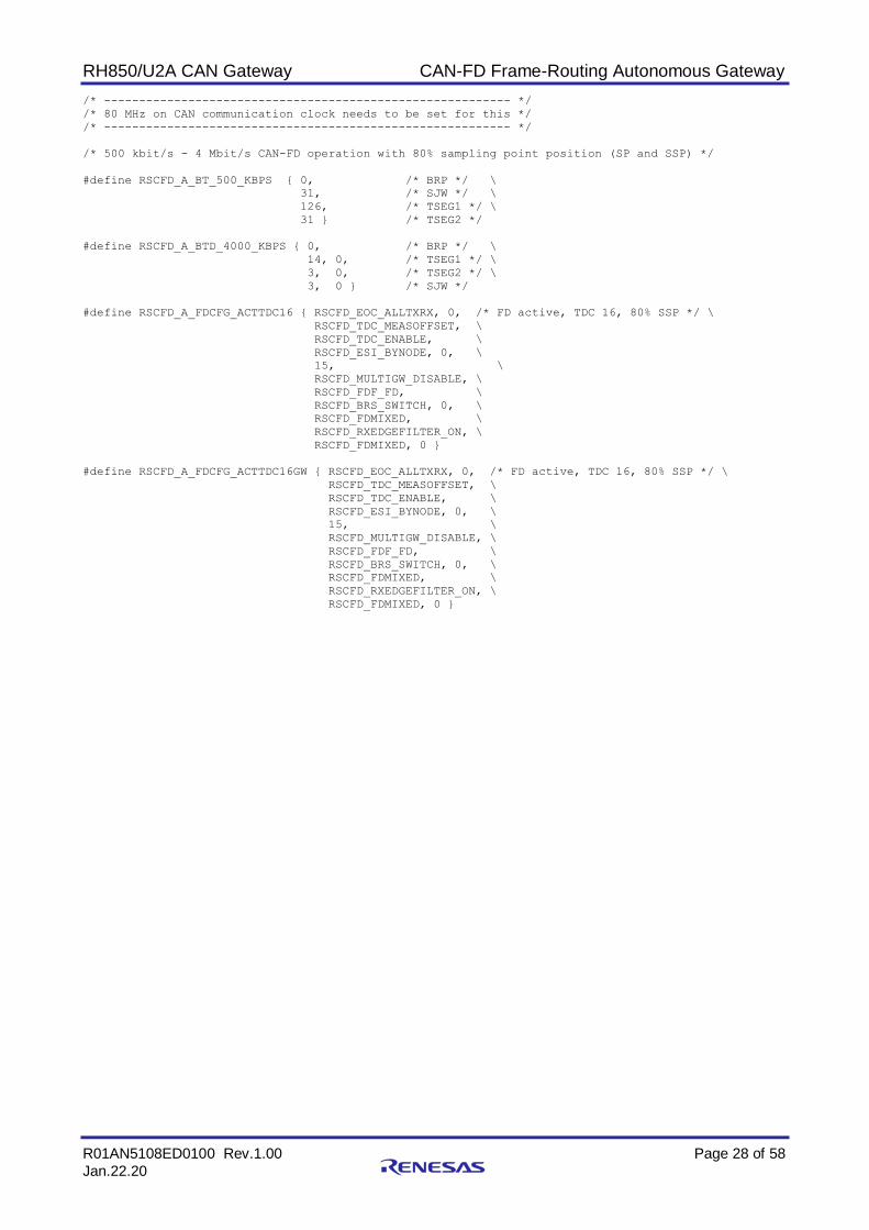
/* 500 kbit/s - 4 Mbit/s CAN-FD operation with 80% sampling point position (SP and SSP) */
#define RSCFD_A_BT_500_KBPS { 0, /* BRP */ \
31, /* SJW */ \
126, /* TSEG1 */ \
31 } /* TSEG2 */
#define RSCFD_A_BTD_4000_KBPS { 0, /* BRP */ \
14, 0, /* TSEG1 */ \
3, 0, /* TSEG2 */ \
3, 0 } /* SJW */
#define RSCFD_A_FDCFG_ACTTDC16 { RSCFD_EOC_ALLTXRX, 0, /* FD active, TDC 16, 80% SSP */ \
RSCFD_TDC_MEASOFFSET, \
RSCFD_TDC_ENABLE, \
RSCFD_ESI_BYNODE, 0, \
15, \
RSCFD_MULTIGW_DISABLE, \
RSCFD_FDF_FD, \
RSCFD_BRS_SWITCH, 0, \
RSCFD_FDMIXED, \
RSCFD_RXEDGEFILTER_ON, \
RSCFD_FDMIXED, 0 }
#define RSCFD_A_FDCFG_ACTTDC16GW { RSCFD_EOC_ALLTXRX, 0, /* FD active, TDC 16, 80% SSP */ \
RSCFD_TDC_MEASOFFSET, \
RSCFD_TDC_ENABLE, \
RSCFD_ESI_BYNODE, 0, \
15, \
RSCFD_MULTIGW_DISABLE, \
RSCFD_FDF_FD, \
RSCFD_BRS_SWITCH, 0, \
RSCFD_FDMIXED, \
RSCFD_RXEDGEFILTER_ON, \
RSCFD_FDMIXED, 0 }

RH850/U2A CAN Gateway CAN-FD Frame-Routing Autonomous Gateway
R01AN5108ED0100 Rev.1.00 Page 29 of 58
Jan.22.20
/* Channel configuration of Channels 0, 2, 4, 6, 8, 10, 12, 14: Hardware Gateway */
const struct rscfd_cfg_channel RSCFD_A_CHHWGW_500_KBPS_4000KBPS = {
0L, 0.0, /* arbitration bitrate manually set */
0L, 0.0, /* data bitrate manually set */
RSCFD_A_BT_500_KBPS, /* arbitration bit timing */
RSCFD_A_BTD_4000_KBPS, /* data bit timing */
{
RSCFD_OPMODE_KEEP, 0, 0, 0, /* No implicit change of Operation Mode */
RSCFD_CINT_TDCVIOL | /* Error Interrupts: Transceiver Compensation */
RSCFD_CINT_BUSLOCK | /* Bus Lock (permanent dominant) */
RSCFD_CINT_BUSOFF, 0, /* Bus Off (recovery ongoing) */
RSCFD_BOM_ISO, 0, /* Standard Bus Off behaviour & Error Signalling */
0, RSCFD_TEST_BASIC, 0, /* Test Mode Off */
0, RSCFD_RESTRICTED_DIS
},
{
RSCFD_OCC_KEEP, /* CAN-FD Occurrence Counter settings */
RSCFD_OCC_KEEP
},
RSCFD_A_FDCFG_ACTTDC16GW, /* CAN-FD with GW Operation Configuration */
{ 0x00000000, 0x00000000 }, /* disable all IRQ of TX Buffers */
RSCFD_A_TXQ_HWGW, /* TX Queues 0~2 in use */
RSCFD_A_THL_OFF, /* THL is off */
{
RSCFD_A_COMFIFO_OFF, /* COMFIFO are all off */
RSCFD_A_COMFIFO_OFF,
RSCFD_A_COMFIFO_OFF
},
{
RSCFD_A_COMFIFO_STD,
RSCFD_A_COMFIFO_STD,
RSCFD_A_COMFIFO_STD
}
};
/* Channel configuration of Channels 1, 3, 5, 7, 9, 11, 13, 15: Receiving only */
const struct rscfd_cfg_channel RSCFD_A_CHRECONLY_500_KBPS_4000KBPS = {
0L, 0.0, /* arbitration bitrate manually set */
0L, 0.0, /* data bitrate manually set */
RSCFD_A_BT_500_KBPS, /* arbitration bit timing */
RSCFD_A_BTD_4000_KBPS, /* data bit timing */
{
RSCFD_OPMODE_KEEP, 0, 0, 0, /* No implicit change of Operation Mode */
RSCFD_CINT_OFF, 0, /* No Error Interrupts */
RSCFD_BOM_ISO, 0, /* Standard Bus Off behaviour & Error Signalling */
0, RSCFD_TEST_BASIC, 0, /* Test Mode Off */
0, RSCFD_RESTRICTED_DIS
},
{
RSCFD_OCC_KEEP, /* CAN-FD Occurrence Counter settings */
RSCFD_OCC_KEEP
},
RSCFD_A_FDCFG_ACTTDC16, /* CAN-FD Operation Configuration */
{ 0x00000000, 0x00000000 }, /* disable all IRQ of TX Buffers */
RSCFD_A_TXQ_OFF, /* TX Queue is off */
RSCFD_A_THL_OFF, /* THL is off */
{
RSCFD_A_COMFIFO_OFF, /* COMFIFO are all off */
RSCFD_A_COMFIFO_OFF,
RSCFD_A_COMFIFO_OFF
},
{
RSCFD_A_COMFIFO_STD,
RSCFD_A_COMFIFO_STD,
RSCFD_A_COMFIFO_STD
}
};
RH850/U2A CAN Gateway CAN-FD Frame-Routing Autonomous Gateway
R01AN5108ED0100 Rev.1.00 Page 30 of 58
Jan.22.20
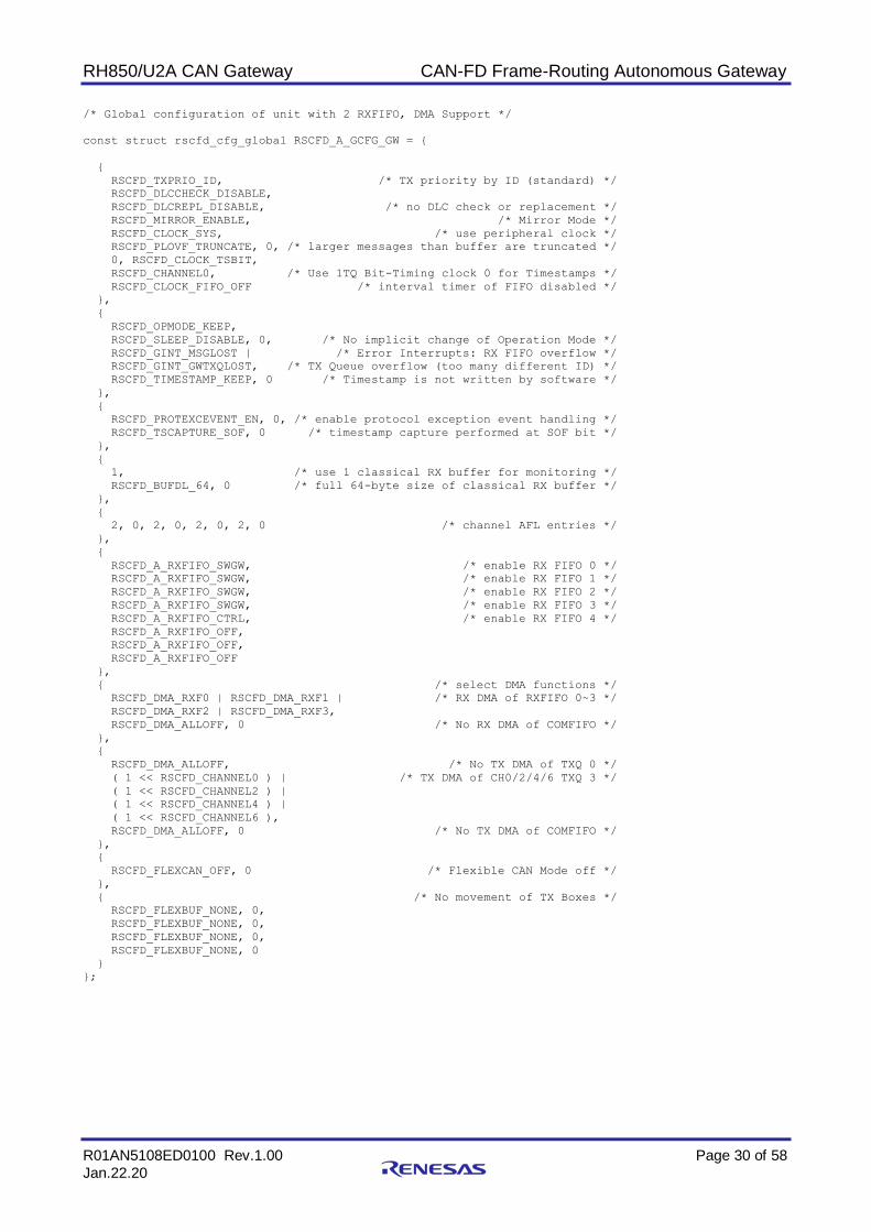
/* Global configuration of unit with 2 RXFIFO, DMA Support */
const struct rscfd_cfg_global RSCFD_A_GCFG_GW = {
{
RSCFD_TXPRIO_ID, /* TX priority by ID (standard) */
RSCFD_DLCCHECK_DISABLE,
RSCFD_DLCREPL_DISABLE, /* no DLC check or replacement */
RSCFD_MIRROR_ENABLE, /* Mirror Mode */
RSCFD_CLOCK_SYS, /* use peripheral clock */
RSCFD_PLOVF_TRUNCATE, 0, /* larger messages than buffer are truncated */
0, RSCFD_CLOCK_TSBIT,
RSCFD_CHANNEL0, /* Use 1TQ Bit-Timing clock 0 for Timestamps */
RSCFD_CLOCK_FIFO_OFF /* interval timer of FIFO disabled */
},
{
RSCFD_OPMODE_KEEP,
RSCFD_SLEEP_DISABLE, 0, /* No implicit change of Operation Mode */
RSCFD_GINT_MSGLOST | /* Error Interrupts: RX FIFO overflow */
RSCFD_GINT_GWTXQLOST, /* TX Queue overflow (too many different ID) */
RSCFD_TIMESTAMP_KEEP, 0 /* Timestamp is not written by software */
},
{
RSCFD_PROTEXCEVENT_EN, 0, /* enable protocol exception event handling */
RSCFD_TSCAPTURE_SOF, 0 /* timestamp capture performed at SOF bit */
},
{
1, /* use 1 classical RX buffer for monitoring */
RSCFD_BUFDL_64, 0 /* full 64-byte size of classical RX buffer */
},
{
2, 0, 2, 0, 2, 0, 2, 0 /* channel AFL entries */
},
{
RSCFD_A_RXFIFO_SWGW, /* enable RX FIFO 0 */
RSCFD_A_RXFIFO_SWGW, /* enable RX FIFO 1 */
RSCFD_A_RXFIFO_SWGW, /* enable RX FIFO 2 */
RSCFD_A_RXFIFO_SWGW, /* enable RX FIFO 3 */
RSCFD_A_RXFIFO_CTRL, /* enable RX FIFO 4 */
RSCFD_A_RXFIFO_OFF,
RSCFD_A_RXFIFO_OFF,
RSCFD_A_RXFIFO_OFF
},
{ /* select DMA functions */
RSCFD_DMA_RXF0 | RSCFD_DMA_RXF1 | /* RX DMA of RXFIFO 0~3 */
RSCFD_DMA_RXF2 | RSCFD_DMA_RXF3,
RSCFD_DMA_ALLOFF, 0 /* No RX DMA of COMFIFO */
},
{
RSCFD_DMA_ALLOFF, /* No TX DMA of TXQ 0 */
( 1 << RSCFD_CHANNEL0 ) | /* TX DMA of CH0/2/4/6 TXQ 3 */
( 1 << RSCFD_CHANNEL2 ) |
( 1 << RSCFD_CHANNEL4 ) |
( 1 << RSCFD_CHANNEL6 ),
RSCFD_DMA_ALLOFF, 0 /* No TX DMA of COMFIFO */
},
{
RSCFD_FLEXCAN_OFF, 0 /* Flexible CAN Mode off */
},
{ /* No movement of TX Boxes */
RSCFD_FLEXBUF_NONE, 0,
RSCFD_FLEXBUF_NONE, 0,
RSCFD_FLEXBUF_NONE, 0,
RSCFD_FLEXBUF_NONE, 0
}
};

RH850/U2A CAN Gateway CAN-FD Frame-Routing Autonomous Gateway
R01AN5108ED0100 Rev.1.00 Page 31 of 58
Jan.22.20
/* Rules to receive all STD ID messages
* into RXFIFO0 for CH0, into CH2,4,6 TX Queues 0, 0, 0; IFL = 00
* into RXFIFO0 for CH2, into CH0,4,6 TX Queues 0, 1, 1; IFL = 01
* into RXFIFO0 for CH4, into CH0,2,6 TX Queues 1, 1, 2; IFL = 10
* into RXFIFO0 for CH6, into CH0,2,4 TX Queues 2, 2, 2 ; IFL = 11
to be handled by the HW Gateway */
struct rscfd_a_afl RSCFD_A_AFL_CH0 = {
{
0x0000000, /* not relevant */
RSCFD_AFL_RXENTRY, /* receive entry type of AFL */
RSCFD_FRAME_DATA, /* RTR data frame configuration */
RSCFD_ID_STD /* standard frame configuration */
},
{
RSCFD_MASK_IDDONTCARE, /* mask is receiving all messages */
RSCFD_AFL_IFL1_MASK( 0L ), /* upper bit of IFL flag */
RSCFD_MASK_FILTER, /* only standard ID data frames */
RSCFD_MASK_FILTER
},
{
RSCFD_DLCCHECK_DISABLE, /* to enable DLC check, enter DLC here */
RSCFD_AFL_SRD_TOTXQ, /* routing to TX-Queues is set */
RSCFD_AFL_SRD_TOTXQ,
RSCFD_AFL_SRD_TOTXQ,
RSCFD_AFL_IFL0_MASK( 0L ), /* lower bit of IFL flag */
0, /* RX Box Number - not relevant for FIFO */
RSCFD_SET, /* RX Box 0 is set active */
0x0000 /* Receive HRH pointer - to be replaced with actual value */
},
{
RSCFD_AFL_RXFIF0_EN0, /* assigned RX-FIFO 0 */
RSCFD_AFL_FIFOTXQ_C2E0 | /* TX-QUEUES 0 of channels 2,4,6 */
RSCFD_AFL_FIFOTXQ_C4E0 |
RSCFD_AFL_FIFOTXQ_C6E0
}
};
struct rscfd_a_afl RSCFD_A_AFL_CH2 = {
{
0x0000000, /* not relevant */
RSCFD_AFL_RXENTRY, /* receive entry type of AFL */
RSCFD_FRAME_DATA, /* RTR data frame configuration */
RSCFD_ID_STD /* standard frame configuration */
},
{
RSCFD_MASK_IDDONTCARE, /* mask is receiving all messages */
RSCFD_AFL_IFL1_MASK( 0L ), /* upper bit of IFL flag */
RSCFD_MASK_FILTER, /* only standard ID data frames */
RSCFD_MASK_FILTER
},
{
RSCFD_DLCCHECK_DISABLE, /* to enable DLC check, enter DLC here */
RSCFD_AFL_SRD_TOTXQ, /* routing to TX-Queues is set */
RSCFD_AFL_SRD_TOTXQ,
RSCFD_AFL_SRD_TOTXQ,
RSCFD_AFL_IFL0_MASK( 1L ), /* lower bit of IFL flag */
0, /* RX Box Number - not relevant for FIFO */
RSCFD_CLEAR, /* RX Box is set inactive */
0x0000 /* Receive HRH pointer - to be replaced with actual value */
},
{
RSCFD_AFL_RXFIF0_EN1, /* assigned RX-FIFO 1 */
RSCFD_AFL_FIFOTXQ_C0E0 | /* TX-QUEUES 0/1 of channels 2,4,6 */
RSCFD_AFL_FIFOTXQ_C4E1 |
RSCFD_AFL_FIFOTXQ_C6E1
}
};

RH850/U2A CAN Gateway CAN-FD Frame-Routing Autonomous Gateway
R01AN5108ED0100 Rev.1.00 Page 32 of 58
Jan.22.20
struct rscfd_a_afl RSCFD_A_AFL_CH4 = {
{
0x0000000, /* not relevant */
RSCFD_AFL_RXENTRY, /* receive entry type of AFL */
RSCFD_FRAME_DATA, /* RTR data frame configuration */
RSCFD_ID_STD /* standard frame configuration */
},
{
RSCFD_MASK_IDDONTCARE, /* mask is receiving all messages */
RSCFD_AFL_IFL1_MASK( 1L ), /* upper bit of IFL flag */
RSCFD_MASK_FILTER, /* only standard ID data frames */
RSCFD_MASK_FILTER
},
{
RSCFD_DLCCHECK_DISABLE, /* to enable DLC check, enter DLC here */
RSCFD_AFL_SRD_TOTXQ, /* routing to TX-Queues is set */
RSCFD_AFL_SRD_TOTXQ,
RSCFD_AFL_SRD_TOTXQ,
RSCFD_AFL_IFL0_MASK( 0L ), /* lower bit of IFL flag */
0, /* RX Box Number - not relevant for FIFO */
RSCFD_CLEAR, /* RX Box is set inactive */
0x0000 /* Receive HRH pointer - to be replaced with actual value */
},
{
RSCFD_AFL_RXFIF0_EN2, /* assigned RX-FIFO 2 */
RSCFD_AFL_FIFOTXQ_C0E0 | /* TX-QUEUES 0/1/2 of channels 2,4,6 */
RSCFD_AFL_FIFOTXQ_C2E1 |
RSCFD_AFL_FIFOTXQ_C6E2
}
};
struct rscfd_a_afl RSCFD_A_AFL_CH6 = {
{
0x0000000, /* not relevant */
RSCFD_AFL_RXENTRY, /* receive entry type of AFL */
RSCFD_FRAME_DATA, /* RTR data frame configuration */
RSCFD_ID_STD /* standard frame configuration */
},
{
RSCFD_MASK_IDDONTCARE, /* mask is receiving all messages */
RSCFD_AFL_IFL1_MASK( 1L ), /* upper bit of IFL flag */
RSCFD_MASK_FILTER, /* only standard ID data frames */
RSCFD_MASK_FILTER
},
{
RSCFD_DLCCHECK_DISABLE, /* to enable DLC check, enter DLC here */
RSCFD_AFL_SRD_TOTXQ, /* routing to TX-Queues is set */
RSCFD_AFL_SRD_TOTXQ,
RSCFD_AFL_SRD_TOTXQ,
RSCFD_AFL_IFL0_MASK( 1L ), /* lower bit of IFL flag */
0, /* RX Box Number - not relevant for FIFO */
RSCFD_CLEAR, /* RX Box is set inactive */
0x0000 /* Receive HRH pointer - to be replaced with actual value */
},
{
RSCFD_AFL_RXFIF0_EN3, /* assigned RX-FIFO 3 */
RSCFD_AFL_FIFOTXQ_C0E2 | /* TX-QUEUES 2 of channels 2,4,6 */
RSCFD_AFL_FIFOTXQ_C2E2 |
RSCFD_AFL_FIFOTXQ_C4E2
}
};

RH850/U2A CAN Gateway CAN-FD Frame-Routing Autonomous Gateway
R01AN5108ED0100 Rev.1.00 Page 33 of 58
Jan.22.20
/* Receive Rule to get Extended ID 0 to message box 0, this is the exit trigger
of the application */
struct rscfd_a_afl RSCFD_A_AFL_RXBOX_EXTID_GWEXIT = {
{
0x0000000, /* Extended ID 0x00000000 to be received only */
RSCFD_AFL_RXENTRY, /* receive entry type of AFL */
RSCFD_FRAME_DATA, /* RTR data frame configuration */
RSCFD_ID_EXT /* extended frame configuration */
},
{
RSCFD_MASK_IDFULLCAN, /* mask is filtering exact match */
RSCFD_AFL_IFL1_MASK( 0L ), /* upper bit of IFL flag */
RSCFD_MASK_FILTER, /* only extended ID data frames */
RSCFD_MASK_FILTER
},
{
RSCFD_DLCCHECK_DISABLE, /* to enable DLC check, enter DLC here */
RSCFD_AFL_SRD_TOCF, /* routing to COMFIFO is default */
RSCFD_AFL_SRD_TOCF,
RSCFD_AFL_SRD_TOCF,
RSCFD_AFL_IFL0_MASK( 0L ), /* lower bit of IFL flag */
0, /* RX Box Number 0 */
RSCFD_CLEAR, /* No RX Box is set */
0x0000 /* Receive HRH pointer - to be replaced with actual value */
},
{
RSCFD_AFL_RXFIF0_EN4, /* RX-FIFO 4 is used */
RSCFD_AFL_COMFIFO_NONE /* COM-FIFO is not used */
}
};
#endif

RH850/U2A CAN Gateway CAN-FD Frame-Routing Autonomous Gateway
R01AN5108ED0100 Rev.1.00 Page 34 of 58
Jan.22.20
5.2 SDMAC Configuration and Global Settings (Multi_Gateway_Test.h)
//============================================================================
// PROJECT = Mutli-Gateway for U2A on X2X NETWORK BOARD
//============================================================================
// C O P Y R I G H T
//============================================================================
// Copyright (c) 2020 by Renesas Electronics (Europe) GmbH. All rights reserved.
// Arcadiastrasse 10
// D-40472 Duesseldorf
// Germany
//============================================================================
//
//Warranty Disclaimer
//
//Because the Product(s) is licensed free of charge, there is no warranty
//of any kind whatsoever and expressly disclaimed and excluded by Renesas,
//either expressed or implied, including but not limited to those for
//non-infringement of intellectual property, merchantability and/or
//fitness for the particular purpose.
//Renesas shall not have any obligation to maintain, service or provide bug
//fixes for the supplied Product(s) and/or the Application.
//
//Each User is solely responsible for determining the appropriateness of
//using the Product(s) and assumes all risks associated with its exercise
//of rights under this Agreement, including, but not limited to the risks
//and costs of program errors, compliance with applicable laws, damage to
//or loss of data, programs or equipment, and unavailability or
//interruption of operations.
//
//Limitation of Liability
//
//In no event shall Renesas be liable to the User for any incidental,
//consequential, indirect, or punitive damage (including but not limited
//to lost profits) regardless of whether such liability is based on breach
//of contract, tort, strict liability, breach of warranties, failure of
//essential purpose or otherwise and even if advised of the possibility of
//such damages. Renesas shall not be liable for any services or products
//provided by third party vendors, developers or consultants identified or
//referred to the User by Renesas in connection with the Product(s) and/or the
//Application.
//
//
//
//============================================================================
// Environment: Devices: RH850/U2A on X2X NETWORK BOARD
// Assembler: GHS MULTI
// C-Compiler: GHS MULTI
// Linker: GHS MULTI
// Debugger: GHS MULTI
//============================================================================
/*
+------------------------------------------------------------------------------+
| Includes |
+------------------------------------------------------------------------------+
*/
#include <map_device.h>
#include <map_ports.h>
#include <map_rscfd.h>
#include <map_dma.h>
#include <map_asmn.h>
#include <stdlib.h>
#include "rscfd_s.h"
RH850/U2A CAN Gateway CAN-FD Frame-Routing Autonomous Gateway
R01AN5108ED0100 Rev.1.00 Page 35 of 58
Jan.22.20
/*
+------------------------------------------------------------------------------+
| Defines |
+------------------------------------------------------------------------------+
*/
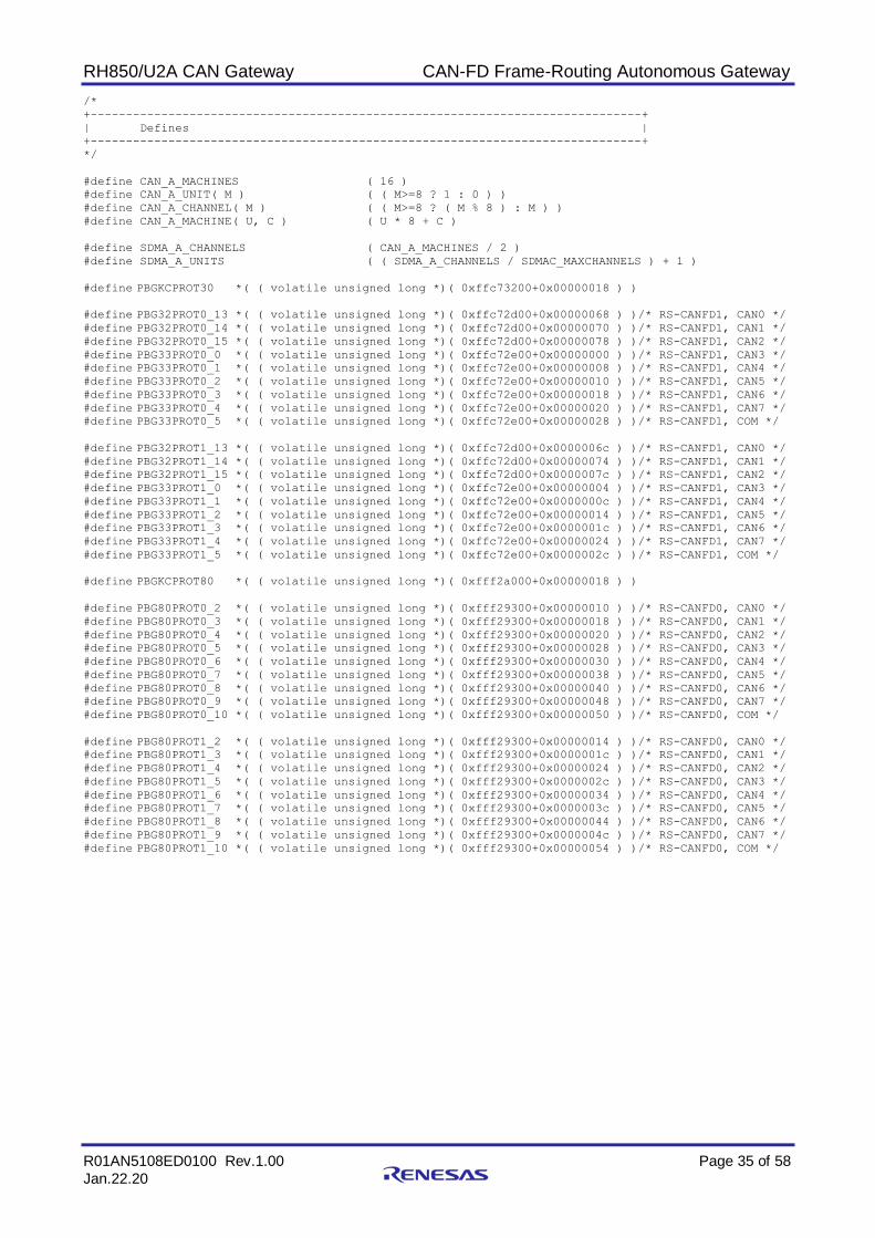
#define CAN_A_MACHINES ( 16 )
#define CAN_A_UNIT( M ) ( ( M>=8 ? 1 : 0 ) )
#define CAN_A_CHANNEL( M ) ( ( M>=8 ? ( M % 8 ) : M ) )
#define CAN_A_MACHINE( U, C ) ( U * 8 + C )
#define SDMA_A_CHANNELS ( CAN_A_MACHINES / 2 )
#define SDMA_A_UNITS ( ( SDMA_A_CHANNELS / SDMAC_MAXCHANNELS ) + 1 )
#define PBGKCPROT30 *( ( volatile unsigned long *)( 0xffc73200+0x00000018 ) )
#define PBG32PROT0_13 *( ( volatile unsigned long *)( 0xffc72d00+0x00000068 ) )/* RS-CANFD1, CAN0 */
#define PBG32PROT0_14 *( ( volatile unsigned long *)( 0xffc72d00+0x00000070 ) )/* RS-CANFD1, CAN1 */
#define PBG32PROT0_15 *( ( volatile unsigned long *)( 0xffc72d00+0x00000078 ) )/* RS-CANFD1, CAN2 */
#define PBG33PROT0_0 *( ( volatile unsigned long *)( 0xffc72e00+0x00000000 ) )/* RS-CANFD1, CAN3 */
#define PBG33PROT0_1 *( ( volatile unsigned long *)( 0xffc72e00+0x00000008 ) )/* RS-CANFD1, CAN4 */
#define PBG33PROT0_2 *( ( volatile unsigned long *)( 0xffc72e00+0x00000010 ) )/* RS-CANFD1, CAN5 */
#define PBG33PROT0_3 *( ( volatile unsigned long *)( 0xffc72e00+0x00000018 ) )/* RS-CANFD1, CAN6 */
#define PBG33PROT0_4 *( ( volatile unsigned long *)( 0xffc72e00+0x00000020 ) )/* RS-CANFD1, CAN7 */
#define PBG33PROT0_5 *( ( volatile unsigned long *)( 0xffc72e00+0x00000028 ) )/* RS-CANFD1, COM */
#define PBG32PROT1_13 *( ( volatile unsigned long *)( 0xffc72d00+0x0000006c ) )/* RS-CANFD1, CAN0 */
#define PBG32PROT1_14 *( ( volatile unsigned long *)( 0xffc72d00+0x00000074 ) )/* RS-CANFD1, CAN1 */
#define PBG32PROT1_15 *( ( volatile unsigned long *)( 0xffc72d00+0x0000007c ) )/* RS-CANFD1, CAN2 */
#define PBG33PROT1_0 *( ( volatile unsigned long *)( 0xffc72e00+0x00000004 ) )/* RS-CANFD1, CAN3 */
#define PBG33PROT1_1 *( ( volatile unsigned long *)( 0xffc72e00+0x0000000c ) )/* RS-CANFD1, CAN4 */
#define PBG33PROT1_2 *( ( volatile unsigned long *)( 0xffc72e00+0x00000014 ) )/* RS-CANFD1, CAN5 */
#define PBG33PROT1_3 *( ( volatile unsigned long *)( 0xffc72e00+0x0000001c ) )/* RS-CANFD1, CAN6 */
#define PBG33PROT1_4 *( ( volatile unsigned long *)( 0xffc72e00+0x00000024 ) )/* RS-CANFD1, CAN7 */
#define PBG33PROT1_5 *( ( volatile unsigned long *)( 0xffc72e00+0x0000002c ) )/* RS-CANFD1, COM */
#define PBGKCPROT80 *( ( volatile unsigned long *)( 0xfff2a000+0x00000018 ) )
#define PBG80PROT0_2 *( ( volatile unsigned long *)( 0xfff29300+0x00000010 ) )/* RS-CANFD0, CAN0 */
#define PBG80PROT0_3 *( ( volatile unsigned long *)( 0xfff29300+0x00000018 ) )/* RS-CANFD0, CAN1 */
#define PBG80PROT0_4 *( ( volatile unsigned long *)( 0xfff29300+0x00000020 ) )/* RS-CANFD0, CAN2 */
#define PBG80PROT0_5 *( ( volatile unsigned long *)( 0xfff29300+0x00000028 ) )/* RS-CANFD0, CAN3 */
#define PBG80PROT0_6 *( ( volatile unsigned long *)( 0xfff29300+0x00000030 ) )/* RS-CANFD0, CAN4 */
#define PBG80PROT0_7 *( ( volatile unsigned long *)( 0xfff29300+0x00000038 ) )/* RS-CANFD0, CAN5 */
#define PBG80PROT0_8 *( ( volatile unsigned long *)( 0xfff29300+0x00000040 ) )/* RS-CANFD0, CAN6 */
#define PBG80PROT0_9 *( ( volatile unsigned long *)( 0xfff29300+0x00000048 ) )/* RS-CANFD0, CAN7 */
#define PBG80PROT0_10 *( ( volatile unsigned long *)( 0xfff29300+0x00000050 ) )/* RS-CANFD0, COM */
#define PBG80PROT1_2 *( ( volatile unsigned long *)( 0xfff29300+0x00000014 ) )/* RS-CANFD0, CAN0 */
#define PBG80PROT1_3 *( ( volatile unsigned long *)( 0xfff29300+0x0000001c ) )/* RS-CANFD0, CAN1 */
#define PBG80PROT1_4 *( ( volatile unsigned long *)( 0xfff29300+0x00000024 ) )/* RS-CANFD0, CAN2 */
#define PBG80PROT1_5 *( ( volatile unsigned long *)( 0xfff29300+0x0000002c ) )/* RS-CANFD0, CAN3 */
#define PBG80PROT1_6 *( ( volatile unsigned long *)( 0xfff29300+0x00000034 ) )/* RS-CANFD0, CAN4 */
#define PBG80PROT1_7 *( ( volatile unsigned long *)( 0xfff29300+0x0000003c ) )/* RS-CANFD0, CAN5 */
#define PBG80PROT1_8 *( ( volatile unsigned long *)( 0xfff29300+0x00000044 ) )/* RS-CANFD0, CAN6 */
#define PBG80PROT1_9 *( ( volatile unsigned long *)( 0xfff29300+0x0000004c ) )/* RS-CANFD0, CAN7 */
#define PBG80PROT1_10 *( ( volatile unsigned long *)( 0xfff29300+0x00000054 ) )/* RS-CANFD0, COM */

RH850/U2A CAN Gateway CAN-FD Frame-Routing Autonomous Gateway
R01AN5108ED0100 Rev.1.00 Page 36 of 58
Jan.22.20
5.3 Gateway Application (Multi_Gateway_Test.c)
//============================================================================
// PROJECT = Mutli-Gateway for U2A on X2X NETWORK BOARD
//============================================================================
// C O P Y R I G H T
//============================================================================
// Copyright (c) 2020 by Renesas Electronics (Europe) GmbH. All rights reserved.
// Arcadiastrasse 10
// D-40472 Duesseldorf
// Germany
//============================================================================
//
//Warranty Disclaimer
//
//Because the Product(s) is licensed free of charge, there is no warranty
//of any kind whatsoever and expressly disclaimed and excluded by Renesas,
//either expressed or implied, including but not limited to those for
//non-infringement of intellectual property, merchantability and/or
//fitness for the particular purpose.
//Renesas shall not have any obligation to maintain, service or provide bug
//fixes for the supplied Product(s) and/or the Application.
//
//Each User is solely responsible for determining the appropriateness of
//using the Product(s) and assumes all risks associated with its exercise
//of rights under this Agreement, including, but not limited to the risks
//and costs of program errors, compliance with applicable laws, damage to
//or loss of data, programs or equipment, and unavailability or
//interruption of operations.
//
//Limitation of Liability
//
//In no event shall Renesas be liable to the User for any incidental,
//consequential, indirect, or punitive damage (including but not limited
//to lost profits) regardless of whether such liability is based on breach
//of contract, tort, strict liability, breach of warranties, failure of
//essential purpose or otherwise and even if advised of the possibility of
//such damages. Renesas shall not be liable for any services or products
//provided by third party vendors, developers or consultants identified or
//referred to the User by Renesas in connection with the Product(s) and/or the
//Application.
//
//
//
//============================================================================
// Environment: Devices: RH850/U2A on X2X NETWORK BOARD
// Assembler: GHS MULTI
// C-Compiler: GHS MULTI
// Linker: GHS MULTI
// Debugger: GHS MULTI
//============================================================================
#include "Multi_Gateway_Test.h"
/*
+------------------------------------------------------------------------------+
| Globals |
+------------------------------------------------------------------------------+
*/
extern u08 RSCFD_LastErrorCode_Global_u08;
extern u08 RSCFD_InterruptFlag_Unit_u08;
static u32 GW_FrameBuffer[ SDMA_A_CHANNELS ][ sizeof( struct rscfd_r_rfmsg ) / 4 ];
bit ExitFlag_bit = false;
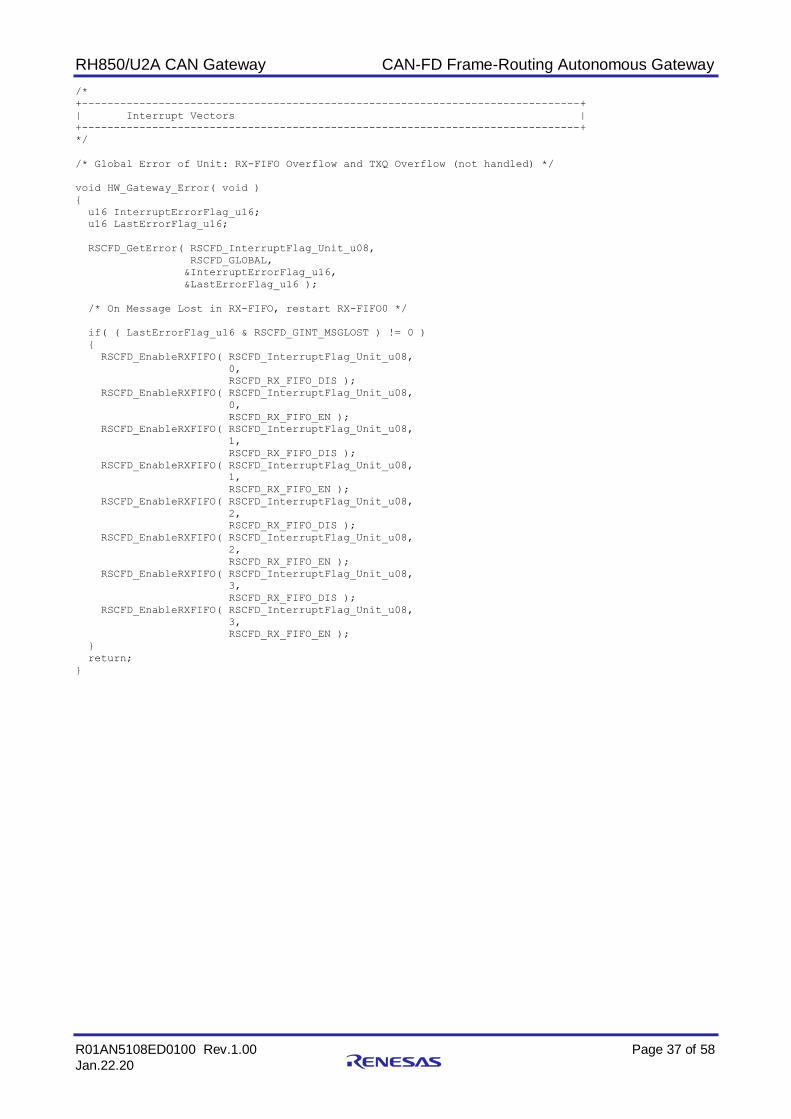
RH850/U2A CAN Gateway CAN-FD Frame-Routing Autonomous Gateway
R01AN5108ED0100 Rev.1.00 Page 37 of 58
Jan.22.20
/*
+------------------------------------------------------------------------------+
| Interrupt Vectors |
+------------------------------------------------------------------------------+
*/
/* Global Error of Unit: RX-FIFO Overflow and TXQ Overflow (not handled) */
void HW_Gateway_Error( void )
{
u16 InterruptErrorFlag_u16;
u16 LastErrorFlag_u16;
RSCFD_GetError( RSCFD_InterruptFlag_Unit_u08,
RSCFD_GLOBAL,
&InterruptErrorFlag_u16,
&LastErrorFlag_u16 );
/* On Message Lost in RX-FIFO, restart RX-FIFO0 */
if( ( LastErrorFlag_u16 & RSCFD_GINT_MSGLOST ) != 0 )
{
RSCFD_EnableRXFIFO( RSCFD_InterruptFlag_Unit_u08,
0,
RSCFD_RX_FIFO_DIS );
RSCFD_EnableRXFIFO( RSCFD_InterruptFlag_Unit_u08,
0,
RSCFD_RX_FIFO_EN );
RSCFD_EnableRXFIFO( RSCFD_InterruptFlag_Unit_u08,
1,
RSCFD_RX_FIFO_DIS );
RSCFD_EnableRXFIFO( RSCFD_InterruptFlag_Unit_u08,
1,
RSCFD_RX_FIFO_EN );
RSCFD_EnableRXFIFO( RSCFD_InterruptFlag_Unit_u08,
2,
RSCFD_RX_FIFO_DIS );
RSCFD_EnableRXFIFO( RSCFD_InterruptFlag_Unit_u08,
2,
RSCFD_RX_FIFO_EN );
RSCFD_EnableRXFIFO( RSCFD_InterruptFlag_Unit_u08,
3,
RSCFD_RX_FIFO_DIS );
RSCFD_EnableRXFIFO( RSCFD_InterruptFlag_Unit_u08,
3,
RSCFD_RX_FIFO_EN );
}
return;
}

RH850/U2A CAN Gateway CAN-FD Frame-Routing Autonomous Gateway
R01AN5108ED0100 Rev.1.00 Page 38 of 58
Jan.22.20
void HW_Gateway_Processing_Exit( void )
{
u08 Unit_u08;
u08 StatusValue_u08;
bit Status_bit = RSCFD_OK;
struct rscfd_message InMessage;
Unit_u08 = RSCFD_InterruptFlag_Unit_u08;
/* fetch message from RX FIFO 1 */
/* Exit condition: message has at least a length of 1 */
do
{
InMessage.path = RSCFD_PATH_RXFIFO;
InMessage.pathdetail = 4;
Status_bit &= RSCFD_ReceiveMessage( Unit_u08,
&StatusValue_u08,
&InMessage );
if( StatusValue_u08 == RSCFD_FAULT_NONE )
{
if( InMessage.flag.dlc >= 1 )
{
ExitFlag_bit = true;
}
}
} while( ( StatusValue_u08 == RSCFD_FAULT_NONE ) &&
( Status_bit != RSCFD_ERROR ) );
return;
}
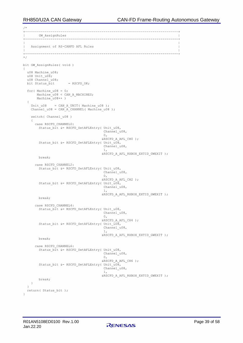
RH850/U2A CAN Gateway CAN-FD Frame-Routing Autonomous Gateway
R01AN5108ED0100 Rev.1.00 Page 39 of 58
Jan.22.20
/*
+------------------------------------------------------------------------------+
| GW_AssignRules |
+------------------------------------------------------------------------------+
| |
| Assignment of RS-CANFD AFL Rules |
| |
+------------------------------------------------------------------------------+
*/
bit GW_AssignRules( void )
{
u08 Machine_u08;
u08 Unit_u08;
u08 Channel_u08;
bit Status_bit = RSCFD_OK;
for( Machine_u08 = 0;
Machine_u08 < CAN_A_MACHINES;
Machine_u08++ )
{
Unit_u08 = CAN_A_UNIT( Machine_u08 );
Channel_u08 = CAN_A_CHANNEL( Machine_u08 );
switch( Channel_u08 )
{
case RSCFD_CHANNEL0:
Status_bit &= RSCFD_SetAFLEntry( Unit_u08,
Channel_u08,
0,
&RSCFD_A_AFL_CH0 );
Status_bit &= RSCFD_SetAFLEntry( Unit_u08,
Channel_u08,
1,
&RSCFD_A_AFL_RXBOX_EXTID_GWEXIT );
break;
case RSCFD_CHANNEL2:
Status_bit &= RSCFD_SetAFLEntry( Unit_u08,
Channel_u08,
0,
&RSCFD_A_AFL_CH2 );
Status_bit &= RSCFD_SetAFLEntry( Unit_u08,
Channel_u08,
1,
&RSCFD_A_AFL_RXBOX_EXTID_GWEXIT );
break;
case RSCFD_CHANNEL4:
Status_bit &= RSCFD_SetAFLEntry( Unit_u08,
Channel_u08,
0,
&RSCFD_A_AFL_CH4 );
Status_bit &= RSCFD_SetAFLEntry( Unit_u08,
Channel_u08,
1,
&RSCFD_A_AFL_RXBOX_EXTID_GWEXIT );
break;
case RSCFD_CHANNEL6:
Status_bit &= RSCFD_SetAFLEntry( Unit_u08,
Channel_u08,
0,
&RSCFD_A_AFL_CH6 );
Status_bit &= RSCFD_SetAFLEntry( Unit_u08,
Channel_u08,
1,
&RSCFD_A_AFL_RXBOX_EXTID_GWEXIT );
break;
}
}
return( Status_bit );
}

RH850/U2A CAN Gateway CAN-FD Frame-Routing Autonomous Gateway
R01AN5108ED0100 Rev.1.00 Page 40 of 58
Jan.22.20
/*
+------------------------------------------------------------------------------+
| GW_ActivateChannels |
+------------------------------------------------------------------------------+
| |
| Activation of Channels: Queues and Operation Modes |
| |
+------------------------------------------------------------------------------+
*/
bit GW_ActivateChannels( void )
{
u08 Machine_u08;
u08 Unit_u08;
u08 Channel_u08;
bit Status_bit = RSCFD_OK;
for( Machine_u08 = 0;
Machine_u08 < CAN_A_MACHINES;
Machine_u08++ )
{
Unit_u08 = CAN_A_UNIT( Machine_u08 );
Channel_u08 = CAN_A_CHANNEL( Machine_u08 );
switch( Channel_u08 )
{
case RSCFD_CHANNEL0:
case RSCFD_CHANNEL2:
case RSCFD_CHANNEL4:
case RSCFD_CHANNEL6:
Status_bit &= RSCFD_SetChannelConfiguration( Unit_u08,
Channel_u08,
&RSCFD_A_CHHWGW_500_KBPS_4000KBPS );
Status_bit &= RSCFD_Start( Unit_u08,
Channel_u08,
RSCFD_OPMODE_OPER, /* operation mode */
RSCFD_CLEAR, /* no error clearing */
RSCFD_SET ); /* timestamp reset */
break;
case RSCFD_CHANNEL1:
case RSCFD_CHANNEL3:
case RSCFD_CHANNEL5:
case RSCFD_CHANNEL7:
Status_bit &= RSCFD_SetChannelConfiguration( Unit_u08,
Channel_u08,
&RSCFD_A_CHRECONLY_500_KBPS_4000KBPS );
Status_bit &= RSCFD_Start( Unit_u08,
Channel_u08,
RSCFD_OPMODE_OPER, /* operation mode */
RSCFD_CLEAR, /* no error clearing */
RSCFD_SET ); /* timestamp reset */
break;
}
}
return( Status_bit );
}
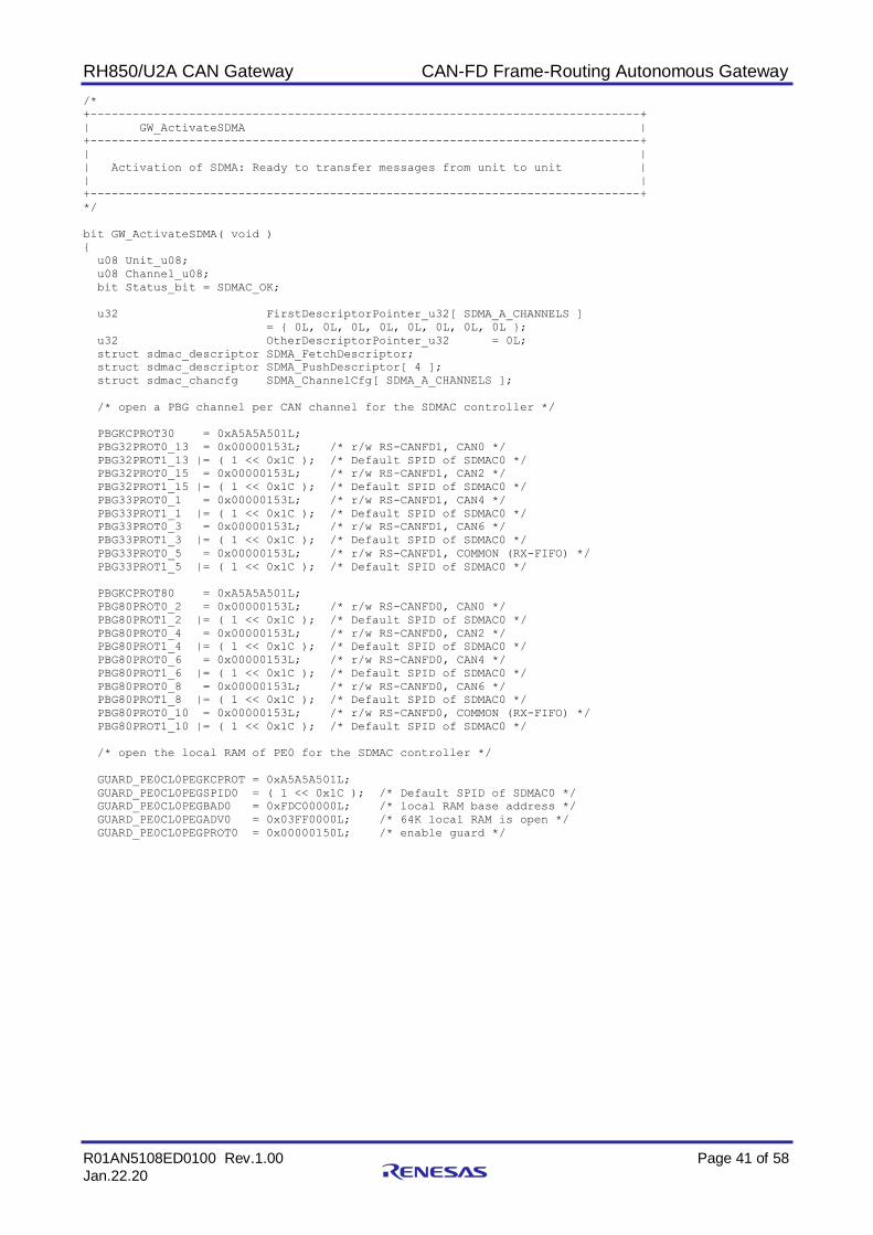
RH850/U2A CAN Gateway CAN-FD Frame-Routing Autonomous Gateway
R01AN5108ED0100 Rev.1.00 Page 41 of 58
Jan.22.20
/*
+------------------------------------------------------------------------------+
| GW_ActivateSDMA |
+------------------------------------------------------------------------------+
| |
| Activation of SDMA: Ready to transfer messages from unit to unit |
| |
+------------------------------------------------------------------------------+
*/
bit GW_ActivateSDMA( void )
{
u08 Unit_u08;
u08 Channel_u08;
bit Status_bit = SDMAC_OK;
u32 FirstDescriptorPointer_u32[ SDMA_A_CHANNELS ]
= { 0L, 0L, 0L, 0L, 0L, 0L, 0L, 0L };
u32 OtherDescriptorPointer_u32 = 0L;
struct sdmac_descriptor SDMA_FetchDescriptor;
struct sdmac_descriptor SDMA_PushDescriptor[ 4 ];
struct sdmac_chancfg SDMA_ChannelCfg[ SDMA_A_CHANNELS ];
/* open a PBG channel per CAN channel for the SDMAC controller */
PBGKCPROT30 = 0xA5A5A501L;
PBG32PROT0_13 = 0x00000153L; /* r/w RS-CANFD1, CAN0 */
PBG32PROT1_13 |= ( 1 << 0x1C ); /* Default SPID of SDMAC0 */
PBG32PROT0_15 = 0x00000153L; /* r/w RS-CANFD1, CAN2 */
PBG32PROT1_15 |= ( 1 << 0x1C ); /* Default SPID of SDMAC0 */
PBG33PROT0_1 = 0x00000153L; /* r/w RS-CANFD1, CAN4 */
PBG33PROT1_1 |= ( 1 << 0x1C ); /* Default SPID of SDMAC0 */
PBG33PROT0_3 = 0x00000153L; /* r/w RS-CANFD1, CAN6 */
PBG33PROT1_3 |= ( 1 << 0x1C ); /* Default SPID of SDMAC0 */
PBG33PROT0_5 = 0x00000153L; /* r/w RS-CANFD1, COMMON (RX-FIFO) */
PBG33PROT1_5 |= ( 1 << 0x1C ); /* Default SPID of SDMAC0 */
PBGKCPROT80 = 0xA5A5A501L;
PBG80PROT0_2 = 0x00000153L; /* r/w RS-CANFD0, CAN0 */
PBG80PROT1_2 |= ( 1 << 0x1C ); /* Default SPID of SDMAC0 */
PBG80PROT0_4 = 0x00000153L; /* r/w RS-CANFD0, CAN2 */
PBG80PROT1_4 |= ( 1 << 0x1C ); /* Default SPID of SDMAC0 */
PBG80PROT0_6 = 0x00000153L; /* r/w RS-CANFD0, CAN4 */
PBG80PROT1_6 |= ( 1 << 0x1C ); /* Default SPID of SDMAC0 */
PBG80PROT0_8 = 0x00000153L; /* r/w RS-CANFD0, CAN6 */
PBG80PROT1_8 |= ( 1 << 0x1C ); /* Default SPID of SDMAC0 */
PBG80PROT0_10 = 0x00000153L; /* r/w RS-CANFD0, COMMON (RX-FIFO) */
PBG80PROT1_10 |= ( 1 << 0x1C ); /* Default SPID of SDMAC0 */
/* open the local RAM of PE0 for the SDMAC controller */
GUARD_PE0CL0PEGKCPROT = 0xA5A5A501L;
GUARD_PE0CL0PEGSPID0 = ( 1 << 0x1C ); /* Default SPID of SDMAC0 */
GUARD_PE0CL0PEGBAD0 = 0xFDC00000L; /* local RAM base address */
GUARD_PE0CL0PEGADV0 = 0x03FF0000L; /* 64K local RAM is open */
GUARD_PE0CL0PEGPROT0 = 0x00000150L; /* enable guard */

RH850/U2A CAN Gateway CAN-FD Frame-Routing Autonomous Gateway
R01AN5108ED0100 Rev.1.00 Page 42 of 58
Jan.22.20
/* Set the RX-FIFO 0 of RSCFD0 read descriptor of channel 0 */
SDMA_FetchDescriptor.sar = ( u32 )( &( rscfd_rxfifo_p[ 0 ]->buf[ 0 ].id ) );
SDMA_FetchDescriptor.dar = ( u32 )( &GW_FrameBuffer[ 0 ][ 0 ] );
SDMA_FetchDescriptor.tsr = 19L * 4;
SDMA_FetchDescriptor.dpcr.upf = ( SDMAC_DESCUPDATEFLAG_SAR |
SDMAC_DESCUPDATEFLAG_DAR |
SDMAC_DESCUPDATEFLAG_TSR );
Status_bit &= SDMAC_SetDescriptor( 0, /* SDMAC Unit 0 */
0, /* Channel 0 */
0 | /* Set Index 0 */
SDMAC_DESC_CHAIN_NUMBER,
&SDMA_FetchDescriptor,
&FirstDescriptorPointer_u32[ 0 ] );
/* Set the TX-Queue write descriptors of SDMAC channel 0 */
SDMA_PushDescriptor[ 0 ].sar = ( u32 )( &GW_FrameBuffer[ 0 ][ 0 ] );
SDMA_PushDescriptor[ 0 ].dar = ( u32 )( &( rscfd_txmsg_p[ 1 ][ 0 ]->buf
[ abs( rscfd_txqentries[ 1 ][ 0 ][ 3 ] ) ].id ) );
SDMA_PushDescriptor[ 0 ].tsr = 19L * 4;
SDMA_PushDescriptor[ 0 ].dpcr.upf = ( SDMAC_DESCUPDATEFLAG_SAR |
SDMAC_DESCUPDATEFLAG_DAR |
SDMAC_DESCUPDATEFLAG_TSR );
SDMA_PushDescriptor[ 1 ].sar = ( u32 )( &GW_FrameBuffer[ 0 ][ 0 ] );
SDMA_PushDescriptor[ 1 ].dar = ( u32 )( &( rscfd_txmsg_p[ 1 ][ 2 ]->buf
[ abs( rscfd_txqentries[ 1 ][ 2 ][ 3 ] ) ].id ) );
SDMA_PushDescriptor[ 1 ].tsr = 19L * 4;
SDMA_PushDescriptor[ 1 ].dpcr.upf = ( SDMAC_DESCUPDATEFLAG_SAR |
SDMAC_DESCUPDATEFLAG_DAR |
SDMAC_DESCUPDATEFLAG_TSR );
SDMA_PushDescriptor[ 2 ].sar = ( u32 )( &GW_FrameBuffer[ 0 ][ 0 ] );
SDMA_PushDescriptor[ 2 ].dar = ( u32 )( &( rscfd_txmsg_p[ 1 ][ 4 ]->buf
[ abs( rscfd_txqentries[ 1 ][ 4 ][ 3 ] ) ].id ) );
SDMA_PushDescriptor[ 2 ].tsr = 19L * 4;
SDMA_PushDescriptor[ 2 ].dpcr.upf = ( SDMAC_DESCUPDATEFLAG_SAR |
SDMAC_DESCUPDATEFLAG_DAR |
SDMAC_DESCUPDATEFLAG_TSR );
SDMA_PushDescriptor[ 3 ].sar = ( u32 )( &GW_FrameBuffer[ 0 ][ 0 ] );
SDMA_PushDescriptor[ 3 ].dar = ( u32 )( &( rscfd_txmsg_p[ 1 ][ 6 ]->buf
[ abs( rscfd_txqentries[ 1 ][ 6 ][ 3 ] ) ].id ) );
SDMA_PushDescriptor[ 3 ].tsr = 19L * 4;
SDMA_PushDescriptor[ 3 ].dpcr.upf = ( SDMAC_DESCUPDATEFLAG_SAR |
SDMAC_DESCUPDATEFLAG_DAR |
SDMAC_DESCUPDATEFLAG_TSR );
Status_bit &= SDMAC_SetDescriptor( 0, /* SDMAC Unit 0 */
0, /* Channel 0 */
SDMAC_DESC_CHAIN_LINKPREVIOUS, /* Add to list */
&SDMA_PushDescriptor[ 0 ],
&OtherDescriptorPointer_u32 );
Status_bit &= SDMAC_SetDescriptor( 0, /* SDMAC Unit 0 */
0, /* Channel 0 */
SDMAC_DESC_CHAIN_LINKPREVIOUS, /* Add to list */
&SDMA_PushDescriptor[ 1 ],
&OtherDescriptorPointer_u32 );
Status_bit &= SDMAC_SetDescriptor( 0, /* SDMAC Unit 0 */
0, /* Channel 0 */
SDMAC_DESC_CHAIN_LINKPREVIOUS, /* Add to list */
&SDMA_PushDescriptor[ 2 ],
&OtherDescriptorPointer_u32 );
Status_bit &= SDMAC_SetDescriptor( 0, /* SDMAC Unit 0 */
0, /* Channel 0 */
SDMAC_DESC_CHAIN_LINKPREVIOUS |
SDMAC_DESC_CHAIN_LINKSTART, /* Add to list */
&SDMA_PushDescriptor[ 3 ],
&OtherDescriptorPointer_u32 );

RH850/U2A CAN Gateway CAN-FD Frame-Routing Autonomous Gateway
R01AN5108ED0100 Rev.1.00 Page 43 of 58
Jan.22.20
/* Set the RX-FIFO 1 of RSCFD0 read descriptor of channel 1 */
SDMA_FetchDescriptor.sar = ( u32 )( &( rscfd_rxfifo_p[ 0 ]->buf[ 1 ].id ) );
SDMA_FetchDescriptor.dar = ( u32 )( &GW_FrameBuffer[ 1 ][ 0 ] );
SDMA_FetchDescriptor.tsr = 19L * 4;
SDMA_FetchDescriptor.dpcr.upf = ( SDMAC_DESCUPDATEFLAG_SAR |
SDMAC_DESCUPDATEFLAG_DAR |
SDMAC_DESCUPDATEFLAG_TSR );
Status_bit &= SDMAC_SetDescriptor( 0, /* SDMAC Unit 0 */
1, /* Channel 1 */
/* At next free place */
SDMAC_DESC_CHAIN_NEXTFREE,
&SDMA_FetchDescriptor,
&FirstDescriptorPointer_u32[ 1 ] );
/* Set the TX-Queue write descriptors of SDMAC channel 1 */
SDMA_PushDescriptor[ 0 ].sar = ( u32 )( &GW_FrameBuffer[ 1 ][ 0 ] );
SDMA_PushDescriptor[ 0 ].dar = ( u32 )( &( rscfd_txmsg_p[ 1 ][ 0 ]->buf
[ abs( rscfd_txqentries[ 1 ][ 0 ][ 3 ] ) ].id ) );
SDMA_PushDescriptor[ 0 ].tsr = 19L * 4;
SDMA_PushDescriptor[ 0 ].dpcr.upf = ( SDMAC_DESCUPDATEFLAG_SAR |
SDMAC_DESCUPDATEFLAG_DAR |
SDMAC_DESCUPDATEFLAG_TSR );
SDMA_PushDescriptor[ 1 ].sar = ( u32 )( &GW_FrameBuffer[ 1 ][ 0 ] );
SDMA_PushDescriptor[ 1 ].dar = ( u32 )( &( rscfd_txmsg_p[ 1 ][ 2 ]->buf
[ abs( rscfd_txqentries[ 1 ][ 2 ][ 3 ] ) ].id ) );
SDMA_PushDescriptor[ 1 ].tsr = 19L * 4;
SDMA_PushDescriptor[ 1 ].dpcr.upf = ( SDMAC_DESCUPDATEFLAG_SAR |
SDMAC_DESCUPDATEFLAG_DAR |
SDMAC_DESCUPDATEFLAG_TSR );
SDMA_PushDescriptor[ 2 ].sar = ( u32 )( &GW_FrameBuffer[ 1 ][ 0 ] );
SDMA_PushDescriptor[ 2 ].dar = ( u32 )( &( rscfd_txmsg_p[ 1 ][ 4 ]->buf
[ abs( rscfd_txqentries[ 1 ][ 4 ][ 3 ] ) ].id ) );
SDMA_PushDescriptor[ 2 ].tsr = 19L * 4;
SDMA_PushDescriptor[ 2 ].dpcr.upf = ( SDMAC_DESCUPDATEFLAG_SAR |
SDMAC_DESCUPDATEFLAG_DAR |
SDMAC_DESCUPDATEFLAG_TSR );
SDMA_PushDescriptor[ 3 ].sar = ( u32 )( &GW_FrameBuffer[ 1 ][ 0 ] );
SDMA_PushDescriptor[ 3 ].dar = ( u32 )( &( rscfd_txmsg_p[ 1 ][ 6 ]->buf
[ abs( rscfd_txqentries[ 1 ][ 6 ][ 3 ] ) ].id ) );
SDMA_PushDescriptor[ 3 ].tsr = 19L * 4;
SDMA_PushDescriptor[ 3 ].dpcr.upf = ( SDMAC_DESCUPDATEFLAG_SAR |
SDMAC_DESCUPDATEFLAG_DAR |
SDMAC_DESCUPDATEFLAG_TSR );
Status_bit &= SDMAC_SetDescriptor( 0, /* SDMAC Unit 0 */
1, /* Channel 1 */
SDMAC_DESC_CHAIN_LINKPREVIOUS, /* Add to list */
&SDMA_PushDescriptor[ 0 ],
&OtherDescriptorPointer_u32 );
Status_bit &= SDMAC_SetDescriptor( 0, /* SDMAC Unit 0 */
1, /* Channel 1 */
SDMAC_DESC_CHAIN_LINKPREVIOUS, /* Add to list */
&SDMA_PushDescriptor[ 1 ],
&OtherDescriptorPointer_u32 );
Status_bit &= SDMAC_SetDescriptor( 0, /* SDMAC Unit 0 */
1, /* Channel 1 */
SDMAC_DESC_CHAIN_LINKPREVIOUS, /* Add to list */
&SDMA_PushDescriptor[ 2 ],
&OtherDescriptorPointer_u32 );
Status_bit &= SDMAC_SetDescriptor( 0, /* SDMAC Unit 0 */
1, /* Channel 1 */
SDMAC_DESC_CHAIN_LINKPREVIOUS |
SDMAC_DESC_CHAIN_LINKSTART, /* Add to list */
&SDMA_PushDescriptor[ 3 ],
&OtherDescriptorPointer_u32 );

RH850/U2A CAN Gateway CAN-FD Frame-Routing Autonomous Gateway
R01AN5108ED0100 Rev.1.00 Page 44 of 58
Jan.22.20
/* Set the RX-FIFO 2 of RSCFD0 read descriptor of channel 2 */
SDMA_FetchDescriptor.sar = ( u32 )( &( rscfd_rxfifo_p[ 0 ]->buf[ 2 ].id ) );
SDMA_FetchDescriptor.dar = ( u32 )( &GW_FrameBuffer[ 2 ][ 0 ] );
SDMA_FetchDescriptor.tsr = 19L * 4;
SDMA_FetchDescriptor.dpcr.upf = ( SDMAC_DESCUPDATEFLAG_SAR |
SDMAC_DESCUPDATEFLAG_DAR |
SDMAC_DESCUPDATEFLAG_TSR );
Status_bit &= SDMAC_SetDescriptor( 0, /* SDMAC Unit 0 */
2, /* Channel 2 */
/* At next free place */
SDMAC_DESC_CHAIN_NEXTFREE,
&SDMA_FetchDescriptor,
&FirstDescriptorPointer_u32[ 2 ] );
/* Set the TX-Queue write descriptors of SDMAC channel 2 */
SDMA_PushDescriptor[ 0 ].sar = ( u32 )( &GW_FrameBuffer[ 2 ][ 0 ] );
SDMA_PushDescriptor[ 0 ].dar = ( u32 )( &( rscfd_txmsg_p[ 1 ][ 0 ]->buf
[ abs( rscfd_txqentries[ 1 ][ 0 ][ 3 ] ) ].id ) );
SDMA_PushDescriptor[ 0 ].tsr = 19L * 4;
SDMA_PushDescriptor[ 0 ].dpcr.upf = ( SDMAC_DESCUPDATEFLAG_SAR |
SDMAC_DESCUPDATEFLAG_DAR |
SDMAC_DESCUPDATEFLAG_TSR );
SDMA_PushDescriptor[ 1 ].sar = ( u32 )( &GW_FrameBuffer[ 2 ][ 0 ] );
SDMA_PushDescriptor[ 1 ].dar = ( u32 )( &( rscfd_txmsg_p[ 1 ][ 2 ]->buf
[ abs( rscfd_txqentries[ 1 ][ 2 ][ 3 ] ) ].id ) );
SDMA_PushDescriptor[ 1 ].tsr = 19L * 4;
SDMA_PushDescriptor[ 1 ].dpcr.upf = ( SDMAC_DESCUPDATEFLAG_SAR |
SDMAC_DESCUPDATEFLAG_DAR |
SDMAC_DESCUPDATEFLAG_TSR );
SDMA_PushDescriptor[ 2 ].sar = ( u32 )( &GW_FrameBuffer[ 2 ][ 0 ] );
SDMA_PushDescriptor[ 2 ].dar = ( u32 )( &( rscfd_txmsg_p[ 1 ][ 4 ]->buf
[ abs( rscfd_txqentries[ 1 ][ 4 ][ 3 ] ) ].id ) );
SDMA_PushDescriptor[ 2 ].tsr = 19L * 4;
SDMA_PushDescriptor[ 2 ].dpcr.upf = ( SDMAC_DESCUPDATEFLAG_SAR |
SDMAC_DESCUPDATEFLAG_DAR |
SDMAC_DESCUPDATEFLAG_TSR );
SDMA_PushDescriptor[ 3 ].sar = ( u32 )( &GW_FrameBuffer[ 2 ][ 0 ] );
SDMA_PushDescriptor[ 3 ].dar = ( u32 )( &( rscfd_txmsg_p[ 1 ][ 6 ]->buf
[ abs( rscfd_txqentries[ 1 ][ 6 ][ 3 ] ) ].id ) );
SDMA_PushDescriptor[ 3 ].tsr = 19L * 4;
SDMA_PushDescriptor[ 3 ].dpcr.upf = ( SDMAC_DESCUPDATEFLAG_SAR |
SDMAC_DESCUPDATEFLAG_DAR |
SDMAC_DESCUPDATEFLAG_TSR );
Status_bit &= SDMAC_SetDescriptor( 0, /* SDMAC Unit 0 */
2, /* Channel 2 */
SDMAC_DESC_CHAIN_LINKPREVIOUS, /* Add to list */
&SDMA_PushDescriptor[ 0 ],
&OtherDescriptorPointer_u32 );
Status_bit &= SDMAC_SetDescriptor( 0, /* SDMAC Unit 0 */
2, /* Channel 2 */
SDMAC_DESC_CHAIN_LINKPREVIOUS, /* Add to list */
&SDMA_PushDescriptor[ 1 ],
&OtherDescriptorPointer_u32 );
Status_bit &= SDMAC_SetDescriptor( 0, /* SDMAC Unit 0 */
2, /* Channel 2 */
SDMAC_DESC_CHAIN_LINKPREVIOUS, /* Add to list */
&SDMA_PushDescriptor[ 2 ],
&OtherDescriptorPointer_u32 );
Status_bit &= SDMAC_SetDescriptor( 0, /* SDMAC Unit 0 */
2, /* Channel 2 */
SDMAC_DESC_CHAIN_LINKPREVIOUS |
SDMAC_DESC_CHAIN_LINKSTART, /* Add to list */
&SDMA_PushDescriptor[ 3 ],
&OtherDescriptorPointer_u32 );

RH850/U2A CAN Gateway CAN-FD Frame-Routing Autonomous Gateway
R01AN5108ED0100 Rev.1.00 Page 45 of 58
Jan.22.20
/* Set the RX-FIFO 3 of RSCFD0 read descriptor of channel 3 */
SDMA_FetchDescriptor.sar = ( u32 )( &( rscfd_rxfifo_p[ 0 ]->buf[ 3 ].id ) );
SDMA_FetchDescriptor.dar = ( u32 )( &GW_FrameBuffer[ 3 ][ 0 ] );
SDMA_FetchDescriptor.tsr = 19L * 4;
SDMA_FetchDescriptor.dpcr.upf = ( SDMAC_DESCUPDATEFLAG_SAR |
SDMAC_DESCUPDATEFLAG_DAR |
SDMAC_DESCUPDATEFLAG_TSR );
Status_bit &= SDMAC_SetDescriptor( 0, /* SDMAC Unit 0 */
3, /* Channel 3 */
/* At next free place */
SDMAC_DESC_CHAIN_NEXTFREE,
&SDMA_FetchDescriptor,
&FirstDescriptorPointer_u32[ 3 ] );
/* Set the TX-Queue write descriptors of SDMAC channel 3 */
SDMA_PushDescriptor[ 0 ].sar = ( u32 )( &GW_FrameBuffer[ 3 ][ 0 ] );
SDMA_PushDescriptor[ 0 ].dar = ( u32 )( &( rscfd_txmsg_p[ 1 ][ 0 ]->buf
[ abs( rscfd_txqentries[ 1 ][ 0 ][ 3 ] ) ].id ) );
SDMA_PushDescriptor[ 0 ].tsr = 19L * 4;
SDMA_PushDescriptor[ 0 ].dpcr.upf = ( SDMAC_DESCUPDATEFLAG_SAR |
SDMAC_DESCUPDATEFLAG_DAR |
SDMAC_DESCUPDATEFLAG_TSR );
SDMA_PushDescriptor[ 1 ].sar = ( u32 )( &GW_FrameBuffer[ 3 ][ 0 ] );
SDMA_PushDescriptor[ 1 ].dar = ( u32 )( &( rscfd_txmsg_p[ 1 ][ 2 ]->buf
[ abs( rscfd_txqentries[ 1 ][ 2 ][ 3 ] ) ].id ) );
SDMA_PushDescriptor[ 1 ].tsr = 19L * 4;
SDMA_PushDescriptor[ 1 ].dpcr.upf = ( SDMAC_DESCUPDATEFLAG_SAR |
SDMAC_DESCUPDATEFLAG_DAR |
SDMAC_DESCUPDATEFLAG_TSR );
SDMA_PushDescriptor[ 2 ].sar = ( u32 )( &GW_FrameBuffer[ 3 ][ 0 ] );
SDMA_PushDescriptor[ 2 ].dar = ( u32 )( &( rscfd_txmsg_p[ 1 ][ 4 ]->buf
[ abs( rscfd_txqentries[ 1 ][ 4 ][ 3 ] ) ].id ) );
SDMA_PushDescriptor[ 2 ].tsr = 19L * 4;
SDMA_PushDescriptor[ 2 ].dpcr.upf = ( SDMAC_DESCUPDATEFLAG_SAR |
SDMAC_DESCUPDATEFLAG_DAR |
SDMAC_DESCUPDATEFLAG_TSR );
SDMA_PushDescriptor[ 3 ].sar = ( u32 )( &GW_FrameBuffer[ 3 ][ 0 ] );
SDMA_PushDescriptor[ 3 ].dar = ( u32 )( &( rscfd_txmsg_p[ 1 ][ 6 ]->buf
[ abs( rscfd_txqentries[ 1 ][ 6 ][ 3 ] ) ].id ) );
SDMA_PushDescriptor[ 3 ].tsr = 19L * 4;
SDMA_PushDescriptor[ 3 ].dpcr.upf = ( SDMAC_DESCUPDATEFLAG_SAR |
SDMAC_DESCUPDATEFLAG_DAR |
SDMAC_DESCUPDATEFLAG_TSR );
Status_bit &= SDMAC_SetDescriptor( 0, /* SDMAC Unit 0 */
3, /* Channel 3 */
SDMAC_DESC_CHAIN_LINKPREVIOUS, /* Add to list */
&SDMA_PushDescriptor[ 0 ],
&OtherDescriptorPointer_u32 );
Status_bit &= SDMAC_SetDescriptor( 0, /* SDMAC Unit 0 */
3, /* Channel 3 */
SDMAC_DESC_CHAIN_LINKPREVIOUS, /* Add to list */
&SDMA_PushDescriptor[ 1 ],
&OtherDescriptorPointer_u32 );
Status_bit &= SDMAC_SetDescriptor( 0, /* SDMAC Unit 0 */
3, /* Channel 3 */
SDMAC_DESC_CHAIN_LINKPREVIOUS, /* Add to list */
&SDMA_PushDescriptor[ 2 ],
&OtherDescriptorPointer_u32 );
Status_bit &= SDMAC_SetDescriptor( 0, /* SDMAC Unit 0 */
3, /* Channel 3 */
SDMAC_DESC_CHAIN_LINKPREVIOUS |
SDMAC_DESC_CHAIN_LINKSTART, /* Add to list */
&SDMA_PushDescriptor[ 3 ],
&OtherDescriptorPointer_u32 );

RH850/U2A CAN Gateway CAN-FD Frame-Routing Autonomous Gateway
R01AN5108ED0100 Rev.1.00 Page 46 of 58
Jan.22.20
/* Set the RX-FIFO 0 of RSCFD 1 read descriptor of SDMAC channel 4 */
SDMA_FetchDescriptor.sar = ( u32 )( &( rscfd_rxfifo_p[ 1 ]->buf[ 0 ].id ) );
SDMA_FetchDescriptor.dar = ( u32 )( &GW_FrameBuffer[ 4 ][ 0 ] );
SDMA_FetchDescriptor.tsr = 19L * 4;
SDMA_FetchDescriptor.dpcr.upf = ( SDMAC_DESCUPDATEFLAG_SAR |
SDMAC_DESCUPDATEFLAG_DAR |
SDMAC_DESCUPDATEFLAG_TSR );
Status_bit &= SDMAC_SetDescriptor( 0, /* SDMAC Unit 0 */
4, /* Channel 4 */
/* At next free place */
SDMAC_DESC_CHAIN_NEXTFREE,
&SDMA_FetchDescriptor,
&FirstDescriptorPointer_u32[ 4 ] );
/* Set the TX-Queue write descriptors of channel 4 */
SDMA_PushDescriptor[ 0 ].sar = ( u32 )( &GW_FrameBuffer[ 4 ][ 0 ] );
SDMA_PushDescriptor[ 0 ].dar = ( u32 )( &( rscfd_txmsg_p[ 0 ][ 0 ]->buf
[ abs( rscfd_txqentries[ 0 ][ 0 ][ 3 ] ) ].id ) );
SDMA_PushDescriptor[ 0 ].tsr = 19L * 4;
SDMA_PushDescriptor[ 0 ].dpcr.upf = ( SDMAC_DESCUPDATEFLAG_SAR |
SDMAC_DESCUPDATEFLAG_DAR |
SDMAC_DESCUPDATEFLAG_TSR );
SDMA_PushDescriptor[ 1 ].sar = ( u32 )( &GW_FrameBuffer[ 4 ][ 0 ] );
SDMA_PushDescriptor[ 1 ].dar = ( u32 )( &( rscfd_txmsg_p[ 0 ][ 2 ]->buf
[ abs( rscfd_txqentries[ 0 ][ 2 ][ 3 ] ) ].id ) );
SDMA_PushDescriptor[ 1 ].tsr = 19L * 4;
SDMA_PushDescriptor[ 1 ].dpcr.upf = ( SDMAC_DESCUPDATEFLAG_SAR |
SDMAC_DESCUPDATEFLAG_DAR |
SDMAC_DESCUPDATEFLAG_TSR );
SDMA_PushDescriptor[ 2 ].sar = ( u32 )( &GW_FrameBuffer[ 4 ][ 0 ] );
SDMA_PushDescriptor[ 2 ].dar = ( u32 )( &( rscfd_txmsg_p[ 0 ][ 4 ]->buf
[ abs( rscfd_txqentries[ 0 ][ 4 ][ 3 ] ) ].id ) );
SDMA_PushDescriptor[ 2 ].tsr = 19L * 4;
SDMA_PushDescriptor[ 2 ].dpcr.upf = ( SDMAC_DESCUPDATEFLAG_SAR |
SDMAC_DESCUPDATEFLAG_DAR |
SDMAC_DESCUPDATEFLAG_TSR );
SDMA_PushDescriptor[ 3 ].sar = ( u32 )( &GW_FrameBuffer[ 4 ][ 0 ] );
SDMA_PushDescriptor[ 3 ].dar = ( u32 )( &( rscfd_txmsg_p[ 0 ][ 6 ]->buf
[ abs( rscfd_txqentries[ 0 ][ 6 ][ 3 ] ) ].id ) );
SDMA_PushDescriptor[ 3 ].tsr = 19L * 4;
SDMA_PushDescriptor[ 3 ].dpcr.upf = ( SDMAC_DESCUPDATEFLAG_SAR |
SDMAC_DESCUPDATEFLAG_DAR |
SDMAC_DESCUPDATEFLAG_TSR );
Status_bit &= SDMAC_SetDescriptor( 0, /* SDMAC Unit 0 */
4, /* Channel 4 */
SDMAC_DESC_CHAIN_LINKPREVIOUS, /* Add to list */
&SDMA_PushDescriptor[ 0 ],
&OtherDescriptorPointer_u32 );
Status_bit &= SDMAC_SetDescriptor( 0, /* SDMAC Unit 0 */
4, /* Channel 4 */
SDMAC_DESC_CHAIN_LINKPREVIOUS, /* Add to list */
&SDMA_PushDescriptor[ 1 ],
&OtherDescriptorPointer_u32 );
Status_bit &= SDMAC_SetDescriptor( 0, /* SDMAC Unit 0 */
4, /* Channel 4 */
SDMAC_DESC_CHAIN_LINKPREVIOUS, /* Add to list */
&SDMA_PushDescriptor[ 2 ],
&OtherDescriptorPointer_u32 );
Status_bit &= SDMAC_SetDescriptor( 0, /* SDMAC Unit 0 */
4, /* Channel 4 */
SDMAC_DESC_CHAIN_LINKPREVIOUS |
SDMAC_DESC_CHAIN_LINKSTART, /* Add to list */
&SDMA_PushDescriptor[ 3 ],
&OtherDescriptorPointer_u32 );

RH850/U2A CAN Gateway CAN-FD Frame-Routing Autonomous Gateway
R01AN5108ED0100 Rev.1.00 Page 47 of 58
Jan.22.20
/* Set the RX-FIFO 1 of RSCFD 1 read descriptor of SDMAC channel 5 */
SDMA_FetchDescriptor.sar = ( u32 )( &( rscfd_rxfifo_p[ 1 ]->buf[ 1 ].id ) );
SDMA_FetchDescriptor.dar = ( u32 )( &GW_FrameBuffer[ 5 ][ 0 ] );
SDMA_FetchDescriptor.tsr = 19L * 4;
SDMA_FetchDescriptor.dpcr.upf = ( SDMAC_DESCUPDATEFLAG_SAR |
SDMAC_DESCUPDATEFLAG_DAR |
SDMAC_DESCUPDATEFLAG_TSR );
Status_bit &= SDMAC_SetDescriptor( 0, /* SDMAC Unit 0 */
5, /* Channel 5 */
/* At next free place */
SDMAC_DESC_CHAIN_NEXTFREE,
&SDMA_FetchDescriptor,
&FirstDescriptorPointer_u32[ 5 ] );
/* Set the TX-Queue write descriptors of channel 5 */
SDMA_PushDescriptor[ 0 ].sar = ( u32 )( &GW_FrameBuffer[ 5 ][ 0 ] );
SDMA_PushDescriptor[ 0 ].dar = ( u32 )( &( rscfd_txmsg_p[ 0 ][ 0 ]->buf
[ abs( rscfd_txqentries[ 0 ][ 0 ][ 3 ] ) ].id ) );
SDMA_PushDescriptor[ 0 ].tsr = 19L * 4;
SDMA_PushDescriptor[ 0 ].dpcr.upf = ( SDMAC_DESCUPDATEFLAG_SAR |
SDMAC_DESCUPDATEFLAG_DAR |
SDMAC_DESCUPDATEFLAG_TSR );
SDMA_PushDescriptor[ 1 ].sar = ( u32 )( &GW_FrameBuffer[ 5 ][ 0 ] );
SDMA_PushDescriptor[ 1 ].dar = ( u32 )( &( rscfd_txmsg_p[ 0 ][ 2 ]->buf
[ abs( rscfd_txqentries[ 0 ][ 2 ][ 3 ] ) ].id ) );
SDMA_PushDescriptor[ 1 ].tsr = 19L * 4;
SDMA_PushDescriptor[ 1 ].dpcr.upf = ( SDMAC_DESCUPDATEFLAG_SAR |
SDMAC_DESCUPDATEFLAG_DAR |
SDMAC_DESCUPDATEFLAG_TSR );
SDMA_PushDescriptor[ 2 ].sar = ( u32 )( &GW_FrameBuffer[ 5 ][ 0 ] );
SDMA_PushDescriptor[ 2 ].dar = ( u32 )( &( rscfd_txmsg_p[ 0 ][ 4 ]-
>buf[ abs( rscfd_txqentries[ 0 ][ 4 ][ 3 ] ) ].id ) );
SDMA_PushDescriptor[ 2 ].tsr = 19L * 4;
SDMA_PushDescriptor[ 2 ].dpcr.upf = ( SDMAC_DESCUPDATEFLAG_SAR |
SDMAC_DESCUPDATEFLAG_DAR |
SDMAC_DESCUPDATEFLAG_TSR );
SDMA_PushDescriptor[ 3 ].sar = ( u32 )( &GW_FrameBuffer[ 5 ][ 0 ] );
SDMA_PushDescriptor[ 3 ].dar = ( u32 )( &( rscfd_txmsg_p[ 0 ][ 6 ]->buf
[ abs( rscfd_txqentries[ 0 ][ 6 ][ 3 ] ) ].id ) );
SDMA_PushDescriptor[ 3 ].tsr = 19L * 4;
SDMA_PushDescriptor[ 3 ].dpcr.upf = ( SDMAC_DESCUPDATEFLAG_SAR |
SDMAC_DESCUPDATEFLAG_DAR |
SDMAC_DESCUPDATEFLAG_TSR );
Status_bit &= SDMAC_SetDescriptor( 0, /* SDMAC Unit 0 */
5, /* Channel 5 */
SDMAC_DESC_CHAIN_LINKPREVIOUS, /* Add to list */
&SDMA_PushDescriptor[ 0 ],
&OtherDescriptorPointer_u32 );
Status_bit &= SDMAC_SetDescriptor( 0, /* SDMAC Unit 0 */
5, /* Channel 5 */
SDMAC_DESC_CHAIN_LINKPREVIOUS, /* Add to list */
&SDMA_PushDescriptor[ 1 ],
&OtherDescriptorPointer_u32 );
Status_bit &= SDMAC_SetDescriptor( 0, /* SDMAC Unit 0 */
5, /* Channel 5 */
SDMAC_DESC_CHAIN_LINKPREVIOUS, /* Add to list */
&SDMA_PushDescriptor[ 2 ],
&OtherDescriptorPointer_u32 );
Status_bit &= SDMAC_SetDescriptor( 0, /* SDMAC Unit 0 */
5, /* Channel 5 */
SDMAC_DESC_CHAIN_LINKPREVIOUS |
SDMAC_DESC_CHAIN_LINKSTART, /* Add to list */
&SDMA_PushDescriptor[ 3 ],
&OtherDescriptorPointer_u32 );

RH850/U2A CAN Gateway CAN-FD Frame-Routing Autonomous Gateway
R01AN5108ED0100 Rev.1.00 Page 48 of 58
Jan.22.20
/* Set the RX-FIFO 2 of RSCFD 1 read descriptor of SDMAC channel 6 */
SDMA_FetchDescriptor.sar = ( u32 )( &( rscfd_rxfifo_p[ 1 ]->buf[ 2 ].id ) );
SDMA_FetchDescriptor.dar = ( u32 )( &GW_FrameBuffer[ 6 ][ 0 ] );
SDMA_FetchDescriptor.tsr = 19L * 4;
SDMA_FetchDescriptor.dpcr.upf = ( SDMAC_DESCUPDATEFLAG_SAR |
SDMAC_DESCUPDATEFLAG_DAR |
SDMAC_DESCUPDATEFLAG_TSR );
Status_bit &= SDMAC_SetDescriptor( 0, /* SDMAC Unit 0 */
6, /* Channel 6 */
/* At next free place */
SDMAC_DESC_CHAIN_NEXTFREE,
&SDMA_FetchDescriptor,
&FirstDescriptorPointer_u32[ 6 ] );
/* Set the TX-Queue write descriptors of channel 6 */
SDMA_PushDescriptor[ 0 ].sar = ( u32 )( &GW_FrameBuffer[ 6 ][ 0 ] );
SDMA_PushDescriptor[ 0 ].dar = ( u32 )( &( rscfd_txmsg_p[ 0 ][ 0 ]->buf
[ abs( rscfd_txqentries[ 0 ][ 0 ][ 3 ] ) ].id ) );
SDMA_PushDescriptor[ 0 ].tsr = 19L * 4;
SDMA_PushDescriptor[ 0 ].dpcr.upf = ( SDMAC_DESCUPDATEFLAG_SAR |
SDMAC_DESCUPDATEFLAG_DAR |
SDMAC_DESCUPDATEFLAG_TSR );
SDMA_PushDescriptor[ 1 ].sar = ( u32 )( &GW_FrameBuffer[ 6 ][ 0 ] );
SDMA_PushDescriptor[ 1 ].dar = ( u32 )( &( rscfd_txmsg_p[ 0 ][ 2 ]->buf
[ abs( rscfd_txqentries[ 0 ][ 2 ][ 3 ] ) ].id ) );
SDMA_PushDescriptor[ 1 ].tsr = 19L * 4;
SDMA_PushDescriptor[ 1 ].dpcr.upf = ( SDMAC_DESCUPDATEFLAG_SAR |
SDMAC_DESCUPDATEFLAG_DAR |
SDMAC_DESCUPDATEFLAG_TSR );
SDMA_PushDescriptor[ 2 ].sar = ( u32 )( &GW_FrameBuffer[ 6 ][ 0 ] );
SDMA_PushDescriptor[ 2 ].dar = ( u32 )( &( rscfd_txmsg_p[ 0 ][ 4 ]->buf
[ abs( rscfd_txqentries[ 0 ][ 4 ][ 3 ] ) ].id ) );
SDMA_PushDescriptor[ 2 ].tsr = 19L * 4;
SDMA_PushDescriptor[ 2 ].dpcr.upf = ( SDMAC_DESCUPDATEFLAG_SAR |
SDMAC_DESCUPDATEFLAG_DAR |
SDMAC_DESCUPDATEFLAG_TSR );
SDMA_PushDescriptor[ 3 ].sar = ( u32 )( &GW_FrameBuffer[ 6 ][ 0 ] );
SDMA_PushDescriptor[ 3 ].dar = ( u32 )( &( rscfd_txmsg_p[ 0 ][ 6 ]->buf
[ abs( rscfd_txqentries[ 0 ][ 6 ][ 3 ] ) ].id ) );
SDMA_PushDescriptor[ 3 ].tsr = 19L * 4;
SDMA_PushDescriptor[ 3 ].dpcr.upf = ( SDMAC_DESCUPDATEFLAG_SAR |
SDMAC_DESCUPDATEFLAG_DAR |
SDMAC_DESCUPDATEFLAG_TSR );
Status_bit &= SDMAC_SetDescriptor( 0, /* SDMAC Unit 0 */
6, /* Channel 6 */
SDMAC_DESC_CHAIN_LINKPREVIOUS, /* Add to list */
&SDMA_PushDescriptor[ 0 ],
&OtherDescriptorPointer_u32 );
Status_bit &= SDMAC_SetDescriptor( 0, /* SDMAC Unit 0 */
6, /* Channel 6 */
SDMAC_DESC_CHAIN_LINKPREVIOUS, /* Add to list */
&SDMA_PushDescriptor[ 1 ],
&OtherDescriptorPointer_u32 );
Status_bit &= SDMAC_SetDescriptor( 0, /* SDMAC Unit 0 */
6, /* Channel 6 */
SDMAC_DESC_CHAIN_LINKPREVIOUS, /* Add to list */
&SDMA_PushDescriptor[ 2 ],
&OtherDescriptorPointer_u32 );
Status_bit &= SDMAC_SetDescriptor( 0, /* SDMAC Unit 0 */
6, /* Channel 6 */
SDMAC_DESC_CHAIN_LINKPREVIOUS |
SDMAC_DESC_CHAIN_LINKSTART, /* Add to list */
&SDMA_PushDescriptor[ 3 ],
&OtherDescriptorPointer_u32 );

RH850/U2A CAN Gateway CAN-FD Frame-Routing Autonomous Gateway
R01AN5108ED0100 Rev.1.00 Page 49 of 58
Jan.22.20
/* Set the RX-FIFO 3 of RSCFD 1 read descriptor of SDMAC channel 7 */
SDMA_FetchDescriptor.sar = ( u32 )( &( rscfd_rxfifo_p[ 1 ]->buf[ 3 ].id ) );
SDMA_FetchDescriptor.dar = ( u32 )( &GW_FrameBuffer[ 7 ][ 0 ] );
SDMA_FetchDescriptor.tsr = 19L * 4;
SDMA_FetchDescriptor.dpcr.upf = ( SDMAC_DESCUPDATEFLAG_SAR |
SDMAC_DESCUPDATEFLAG_DAR |
SDMAC_DESCUPDATEFLAG_TSR );
Status_bit &= SDMAC_SetDescriptor( 0, /* SDMAC Unit 0 */
7, /* Channel 7 */
/* At next free place */
SDMAC_DESC_CHAIN_NEXTFREE,
&SDMA_FetchDescriptor,
&FirstDescriptorPointer_u32[ 7 ] );
/* Set the TX-Queue write descriptors of channel 7 */
SDMA_PushDescriptor[ 0 ].sar = ( u32 )( &GW_FrameBuffer[ 7 ][ 0 ] );
SDMA_PushDescriptor[ 0 ].dar = ( u32 )( &( rscfd_txmsg_p[ 0 ][ 0 ]->buf
[ abs( rscfd_txqentries[ 0 ][ 0 ][ 3 ] ) ].id ) );
SDMA_PushDescriptor[ 0 ].tsr = 19L * 4;
SDMA_PushDescriptor[ 0 ].dpcr.upf = ( SDMAC_DESCUPDATEFLAG_SAR |
SDMAC_DESCUPDATEFLAG_DAR |
SDMAC_DESCUPDATEFLAG_TSR );
SDMA_PushDescriptor[ 1 ].sar = ( u32 )( &GW_FrameBuffer[ 7 ][ 0 ] );
SDMA_PushDescriptor[ 1 ].dar = ( u32 )( &( rscfd_txmsg_p[ 0 ][ 2 ]->buf
[ abs( rscfd_txqentries[ 0 ][ 2 ][ 3 ] ) ].id ) );
SDMA_PushDescriptor[ 1 ].tsr = 19L * 4;
SDMA_PushDescriptor[ 1 ].dpcr.upf = ( SDMAC_DESCUPDATEFLAG_SAR |
SDMAC_DESCUPDATEFLAG_DAR |
SDMAC_DESCUPDATEFLAG_TSR );
SDMA_PushDescriptor[ 2 ].sar = ( u32 )( &GW_FrameBuffer[ 7 ][ 0 ] );
SDMA_PushDescriptor[ 2 ].dar = ( u32 )( &( rscfd_txmsg_p[ 0 ][ 4 ]->buf
[ abs( rscfd_txqentries[ 0 ][ 4 ][ 3 ] ) ].id ) );
SDMA_PushDescriptor[ 2 ].tsr = 19L * 4;
SDMA_PushDescriptor[ 2 ].dpcr.upf = ( SDMAC_DESCUPDATEFLAG_SAR |
SDMAC_DESCUPDATEFLAG_DAR |
SDMAC_DESCUPDATEFLAG_TSR );
SDMA_PushDescriptor[ 3 ].sar = ( u32 )( &GW_FrameBuffer[ 7 ][ 0 ] );
SDMA_PushDescriptor[ 3 ].dar = ( u32 )( &( rscfd_txmsg_p[ 0 ][ 6 ]->buf
[ abs( rscfd_txqentries[ 0 ][ 6 ][ 3 ] ) ].id ) );
SDMA_PushDescriptor[ 3 ].tsr = 19L * 4;
SDMA_PushDescriptor[ 3 ].dpcr.upf = ( SDMAC_DESCUPDATEFLAG_SAR |
SDMAC_DESCUPDATEFLAG_DAR |
SDMAC_DESCUPDATEFLAG_TSR );
Status_bit &= SDMAC_SetDescriptor( 0, /* SDMAC Unit 0 */
7, /* Channel 7 */
SDMAC_DESC_CHAIN_LINKPREVIOUS, /* Add to list */
&SDMA_PushDescriptor[ 0 ],
&OtherDescriptorPointer_u32 );
Status_bit &= SDMAC_SetDescriptor( 0, /* SDMAC Unit 0 */
7, /* Channel 7 */
SDMAC_DESC_CHAIN_LINKPREVIOUS, /* Add to list */
&SDMA_PushDescriptor[ 1 ],
&OtherDescriptorPointer_u32 );
Status_bit &= SDMAC_SetDescriptor( 0, /* SDMAC Unit 0 */
7, /* Channel 7 */
SDMAC_DESC_CHAIN_LINKPREVIOUS, /* Add to list */
&SDMA_PushDescriptor[ 2 ],
&OtherDescriptorPointer_u32 );
Status_bit &= SDMAC_SetDescriptor( 0, /* SDMAC Unit 0 */
7, /* Channel 7 */
SDMAC_DESC_CHAIN_LINKPREVIOUS |
SDMAC_DESC_CHAIN_LINKSTART, /* Add to list */
&SDMA_PushDescriptor[ 3 ],
&OtherDescriptorPointer_u32 );

RH850/U2A CAN Gateway CAN-FD Frame-Routing Autonomous Gateway
R01AN5108ED0100 Rev.1.00 Page 50 of 58
Jan.22.20
/* Set the channel configurations */
/* assign trigger factor 45 (RX-FIFO0 of CAN unit 0) to SDMAC0.0 factor 45 */
SDMA_ChannelCfg[ 0 ].rs.b.rs = 45L; /* Trigger Factor */
/* Master settings */
SDMA_ChannelCfg[ 0 ].cm.um = SDMAC_CLEAR; /* Supervisor Mode */
SDMA_ChannelCfg[ 0 ].cm.spid = 0x1C; /* Default SPID */
/* Transfer settings */
SDMA_ChannelCfg[ 0 ].tsr = 0L; /* Force the descriptor usage */
SDMA_ChannelCfg[ 0 ].tmr.b.sts = SDMAC_TRANSSIZE_4BYTE;
SDMA_ChannelCfg[ 0 ].tmr.b.dts = SDMAC_TRANSSIZE_4BYTE;
SDMA_ChannelCfg[ 0 ].tmr.b.sm = SDMAC_ADDRESSMODE_INCREMENT;
SDMA_ChannelCfg[ 0 ].tmr.b.dm = SDMAC_ADDRESSMODE_INCREMENT;
SDMA_ChannelCfg[ 0 ].tmr.b.trs = SDMAC_REQUESTSOURCE_HARDWARE;
SDMA_ChannelCfg[ 0 ].tmr.b.pri = 0L;
SDMA_ChannelCfg[ 0 ].tmr.b.prien = 0L;
SDMA_ChannelCfg[ 0 ].tmr.b.slm = SDMAC_SLOWSPEED_OFF;
SDMA_ChannelCfg[ 0 ].sgcr.b.gen = SDMAC_CLEAR;
SDMA_ChannelCfg[ 0 ].sgcr.b.sen = SDMAC_CLEAR;
SDMA_ChannelCfg[ 0 ].rs.b.drqi = SDMAC_CLEAR;
SDMA_ChannelCfg[ 0 ].rs.b.ple = SDMAC_CLEAR;
SDMA_ChannelCfg[ 0 ].rs.b.fpt = SDMAC_CLEAR;
SDMA_ChannelCfg[ 0 ].rs.b.tl = SDMAC_TRLIMIT_BY_STS_TC;
SDMA_ChannelCfg[ 0 ].rs.b.tc = 19L * 5;
SDMA_ChannelCfg[ 0 ].chcr.dpb = SDMAC_CLEAR;
SDMA_ChannelCfg[ 0 ].chcr.dpe = SDMAC_SET;
SDMA_ChannelCfg[ 0 ].bufcr.b.ulb = SDMAC_BUFFERLIMIT_DEFAULT;
SDMA_ChannelCfg[ 0 ].dpptr.cf = SDMAC_SET;
SDMA_ChannelCfg[ 0 ].dpptr.ptr = ( FirstDescriptorPointer_u32[ 0 ] ) >> 2;
SDMA_ChannelCfg[ 0 ].dpcr.upf = ( SDMAC_DESCUPDATEFLAG_SAR |
SDMAC_DESCUPDATEFLAG_DAR |
SDMAC_DESCUPDATEFLAG_TSR );
/* assign trigger factor 46 (RX-FIFO1 of CAN unit 0) to SDMAC0.1 factor 46 */
SDMA_ChannelCfg[ 1 ].rs.b.rs = 46L; /* Trigger Factor */
/* Master settings */
SDMA_ChannelCfg[ 1 ].cm.um = SDMAC_CLEAR; /* Supervisor Mode */
SDMA_ChannelCfg[ 1 ].cm.spid = 0x1C; /* Default SPID */
/* Transfer settings */
SDMA_ChannelCfg[ 1 ].tsr = 0L; /* Force the descriptor usage */
SDMA_ChannelCfg[ 1 ].tmr.b.sts = SDMAC_TRANSSIZE_4BYTE;
SDMA_ChannelCfg[ 1 ].tmr.b.dts = SDMAC_TRANSSIZE_4BYTE;
SDMA_ChannelCfg[ 1 ].tmr.b.sm = SDMAC_ADDRESSMODE_INCREMENT;
SDMA_ChannelCfg[ 1 ].tmr.b.dm = SDMAC_ADDRESSMODE_INCREMENT;
SDMA_ChannelCfg[ 1 ].tmr.b.trs = SDMAC_REQUESTSOURCE_HARDWARE;
SDMA_ChannelCfg[ 1 ].tmr.b.pri = 0L;
SDMA_ChannelCfg[ 1 ].tmr.b.prien = 0L;
SDMA_ChannelCfg[ 1 ].tmr.b.slm = SDMAC_SLOWSPEED_OFF;
SDMA_ChannelCfg[ 1 ].sgcr.b.gen = SDMAC_CLEAR;
SDMA_ChannelCfg[ 1 ].sgcr.b.sen = SDMAC_CLEAR;
SDMA_ChannelCfg[ 1 ].rs.b.drqi = SDMAC_CLEAR;
SDMA_ChannelCfg[ 1 ].rs.b.ple = SDMAC_CLEAR;
SDMA_ChannelCfg[ 1 ].rs.b.fpt = SDMAC_CLEAR;
SDMA_ChannelCfg[ 1 ].rs.b.tl = SDMAC_TRLIMIT_BY_STS_TC;
SDMA_ChannelCfg[ 1 ].rs.b.tc = 19L * 5;
SDMA_ChannelCfg[ 1 ].chcr.dpb = SDMAC_CLEAR;
SDMA_ChannelCfg[ 1 ].chcr.dpe = SDMAC_SET;
SDMA_ChannelCfg[ 1 ].bufcr.b.ulb = SDMAC_BUFFERLIMIT_DEFAULT;
SDMA_ChannelCfg[ 1 ].dpptr.cf = SDMAC_SET;
SDMA_ChannelCfg[ 1 ].dpptr.ptr = ( FirstDescriptorPointer_u32[ 1 ] ) >> 2;
SDMA_ChannelCfg[ 1 ].dpcr.upf = ( SDMAC_DESCUPDATEFLAG_SAR |
SDMAC_DESCUPDATEFLAG_DAR |
SDMAC_DESCUPDATEFLAG_TSR );

RH850/U2A CAN Gateway CAN-FD Frame-Routing Autonomous Gateway
R01AN5108ED0100 Rev.1.00 Page 51 of 58
Jan.22.20
/* assign trigger factor 47 (RX-FIFO2 of CAN unit 0) to SDMAC0.2 factor 47 */
SDMA_ChannelCfg[ 2 ].rs.b.rs = 47L; /* Trigger Factor */
/* Master settings */
SDMA_ChannelCfg[ 2 ].cm.um = SDMAC_CLEAR; /* Supervisor Mode */
SDMA_ChannelCfg[ 2 ].cm.spid = 0x1C; /* Default SPID */
/* Transfer settings */
SDMA_ChannelCfg[ 2 ].tsr = 0L; /* Force the descriptor usage */
SDMA_ChannelCfg[ 2 ].tmr.b.sts = SDMAC_TRANSSIZE_4BYTE;
SDMA_ChannelCfg[ 2 ].tmr.b.dts = SDMAC_TRANSSIZE_4BYTE;
SDMA_ChannelCfg[ 2 ].tmr.b.sm = SDMAC_ADDRESSMODE_INCREMENT;
SDMA_ChannelCfg[ 2 ].tmr.b.dm = SDMAC_ADDRESSMODE_INCREMENT;
SDMA_ChannelCfg[ 2 ].tmr.b.trs = SDMAC_REQUESTSOURCE_HARDWARE;
SDMA_ChannelCfg[ 2 ].tmr.b.pri = 0L;
SDMA_ChannelCfg[ 2 ].tmr.b.prien = 0L;
SDMA_ChannelCfg[ 2 ].tmr.b.slm = SDMAC_SLOWSPEED_OFF;
SDMA_ChannelCfg[ 2 ].sgcr.b.gen = SDMAC_CLEAR;
SDMA_ChannelCfg[ 2 ].sgcr.b.sen = SDMAC_CLEAR;
SDMA_ChannelCfg[ 2 ].rs.b.drqi = SDMAC_CLEAR;
SDMA_ChannelCfg[ 2 ].rs.b.ple = SDMAC_CLEAR;
SDMA_ChannelCfg[ 2 ].rs.b.fpt = SDMAC_CLEAR;
SDMA_ChannelCfg[ 2 ].rs.b.tl = SDMAC_TRLIMIT_BY_STS_TC;
SDMA_ChannelCfg[ 2 ].rs.b.tc = 19L * 5;
SDMA_ChannelCfg[ 2 ].chcr.dpb = SDMAC_CLEAR;
SDMA_ChannelCfg[ 2 ].chcr.dpe = SDMAC_SET;
SDMA_ChannelCfg[ 2 ].bufcr.b.ulb = SDMAC_BUFFERLIMIT_DEFAULT;
SDMA_ChannelCfg[ 2 ].dpptr.cf = SDMAC_SET;
SDMA_ChannelCfg[ 2 ].dpptr.ptr = ( FirstDescriptorPointer_u32[ 2 ] ) >> 2;
SDMA_ChannelCfg[ 2 ].dpcr.upf = ( SDMAC_DESCUPDATEFLAG_SAR |
SDMAC_DESCUPDATEFLAG_DAR |
SDMAC_DESCUPDATEFLAG_TSR );
/* assign trigger factor 48 (RX-FIFO3 of CAN unit 0) to SDMAC0.3 factor 48 */
SDMA_ChannelCfg[ 3 ].rs.b.rs = 48L; /* Trigger Factor */
/* Master settings */
SDMA_ChannelCfg[ 3 ].cm.um = SDMAC_CLEAR; /* Supervisor Mode */
SDMA_ChannelCfg[ 3 ].cm.spid = 0x1C; /* Default SPID */
/* Transfer settings */
SDMA_ChannelCfg[ 3 ].tsr = 0L; /* Force the descriptor usage */
SDMA_ChannelCfg[ 3 ].tmr.b.sts = SDMAC_TRANSSIZE_4BYTE;
SDMA_ChannelCfg[ 3 ].tmr.b.dts = SDMAC_TRANSSIZE_4BYTE;
SDMA_ChannelCfg[ 3 ].tmr.b.sm = SDMAC_ADDRESSMODE_INCREMENT;
SDMA_ChannelCfg[ 3 ].tmr.b.dm = SDMAC_ADDRESSMODE_INCREMENT;
SDMA_ChannelCfg[ 3 ].tmr.b.trs = SDMAC_REQUESTSOURCE_HARDWARE;
SDMA_ChannelCfg[ 3 ].tmr.b.pri = 0L;
SDMA_ChannelCfg[ 3 ].tmr.b.prien = 0L;
SDMA_ChannelCfg[ 3 ].tmr.b.slm = SDMAC_SLOWSPEED_OFF;
SDMA_ChannelCfg[ 3 ].sgcr.b.gen = SDMAC_CLEAR;
SDMA_ChannelCfg[ 3 ].sgcr.b.sen = SDMAC_CLEAR;
SDMA_ChannelCfg[ 3 ].rs.b.drqi = SDMAC_CLEAR;
SDMA_ChannelCfg[ 3 ].rs.b.ple = SDMAC_CLEAR;
SDMA_ChannelCfg[ 3 ].rs.b.fpt = SDMAC_CLEAR;
SDMA_ChannelCfg[ 3 ].rs.b.tl = SDMAC_TRLIMIT_BY_STS_TC;
SDMA_ChannelCfg[ 3 ].rs.b.tc = 19L * 5;
SDMA_ChannelCfg[ 3 ].chcr.dpb = SDMAC_CLEAR;
SDMA_ChannelCfg[ 3 ].chcr.dpe = SDMAC_SET;
SDMA_ChannelCfg[ 3 ].bufcr.b.ulb = SDMAC_BUFFERLIMIT_DEFAULT;
SDMA_ChannelCfg[ 3 ].dpptr.cf = SDMAC_SET;
SDMA_ChannelCfg[ 3 ].dpptr.ptr = ( FirstDescriptorPointer_u32[ 3 ] ) >> 2;
SDMA_ChannelCfg[ 3 ].dpcr.upf = ( SDMAC_DESCUPDATEFLAG_SAR |
SDMAC_DESCUPDATEFLAG_DAR |
SDMAC_DESCUPDATEFLAG_TSR );

RH850/U2A CAN Gateway CAN-FD Frame-Routing Autonomous Gateway
R01AN5108ED0100 Rev.1.00 Page 52 of 58
Jan.22.20
/* assign trigger factor 53 (RX-FIFO0 of CAN unit 1) to SDMAC0.4 factor 53 */
SDMA_ChannelCfg[ 4 ].rs.b.rs = 53L; /* Trigger Factor */
/* Master settings */
SDMA_ChannelCfg[ 4 ].cm.um = SDMAC_CLEAR; /* Supervisor Mode */
SDMA_ChannelCfg[ 4 ].cm.spid = 0x1C; /* Default SPID */
/* Transfer settings */
SDMA_ChannelCfg[ 4 ].tsr = 0L; /* Force the descriptor usage */
SDMA_ChannelCfg[ 4 ].tmr.b.sts = SDMAC_TRANSSIZE_4BYTE;
SDMA_ChannelCfg[ 4 ].tmr.b.dts = SDMAC_TRANSSIZE_4BYTE;
SDMA_ChannelCfg[ 4 ].tmr.b.sm = SDMAC_ADDRESSMODE_INCREMENT;
SDMA_ChannelCfg[ 4 ].tmr.b.dm = SDMAC_ADDRESSMODE_INCREMENT;
SDMA_ChannelCfg[ 4 ].tmr.b.trs = SDMAC_REQUESTSOURCE_HARDWARE;
SDMA_ChannelCfg[ 4 ].tmr.b.pri = 0L;
SDMA_ChannelCfg[ 4 ].tmr.b.prien = 0L;
SDMA_ChannelCfg[ 4 ].tmr.b.slm = SDMAC_SLOWSPEED_OFF;
SDMA_ChannelCfg[ 4 ].sgcr.b.gen = SDMAC_CLEAR;
SDMA_ChannelCfg[ 4 ].sgcr.b.sen = SDMAC_CLEAR;
SDMA_ChannelCfg[ 4 ].rs.b.drqi = SDMAC_CLEAR;
SDMA_ChannelCfg[ 4 ].rs.b.ple = SDMAC_CLEAR;
SDMA_ChannelCfg[ 4 ].rs.b.fpt = SDMAC_CLEAR;
SDMA_ChannelCfg[ 4 ].rs.b.tl = SDMAC_TRLIMIT_BY_STS_TC;
SDMA_ChannelCfg[ 4 ].rs.b.tc = 19L * 5;
SDMA_ChannelCfg[ 4 ].chcr.dpb = SDMAC_CLEAR;
SDMA_ChannelCfg[ 4 ].chcr.dpe = SDMAC_SET;
SDMA_ChannelCfg[ 4 ].bufcr.b.ulb = SDMAC_BUFFERLIMIT_DEFAULT;
SDMA_ChannelCfg[ 4 ].dpptr.cf = SDMAC_SET;
SDMA_ChannelCfg[ 4 ].dpptr.ptr = ( FirstDescriptorPointer_u32[ 4 ] ) >> 2;
SDMA_ChannelCfg[ 4 ].dpcr.upf = ( SDMAC_DESCUPDATEFLAG_SAR |
SDMAC_DESCUPDATEFLAG_DAR |
SDMAC_DESCUPDATEFLAG_TSR );
/* assign trigger factor 54 (RX-FIFO1 of CAN unit 1) to SDMAC0.5 factor 54 */
SDMA_ChannelCfg[ 5 ].rs.b.rs = 54L; /* Trigger Factor */
/* Master settings */
SDMA_ChannelCfg[ 5 ].cm.um = SDMAC_CLEAR; /* Supervisor Mode */
SDMA_ChannelCfg[ 5 ].cm.spid = 0x1C; /* Default SPID */
/* Transfer settings */
SDMA_ChannelCfg[ 5 ].tsr = 0L; /* Force the descriptor usage */
SDMA_ChannelCfg[ 5 ].tmr.b.sts = SDMAC_TRANSSIZE_4BYTE;
SDMA_ChannelCfg[ 5 ].tmr.b.dts = SDMAC_TRANSSIZE_4BYTE;
SDMA_ChannelCfg[ 5 ].tmr.b.sm = SDMAC_ADDRESSMODE_INCREMENT;
SDMA_ChannelCfg[ 5 ].tmr.b.dm = SDMAC_ADDRESSMODE_INCREMENT;
SDMA_ChannelCfg[ 5 ].tmr.b.trs = SDMAC_REQUESTSOURCE_HARDWARE;
SDMA_ChannelCfg[ 5 ].tmr.b.pri = 0L;
SDMA_ChannelCfg[ 5 ].tmr.b.prien = 0L;
SDMA_ChannelCfg[ 5 ].tmr.b.slm = SDMAC_SLOWSPEED_OFF;
SDMA_ChannelCfg[ 5 ].sgcr.b.gen = SDMAC_CLEAR;
SDMA_ChannelCfg[ 5 ].sgcr.b.sen = SDMAC_CLEAR;
SDMA_ChannelCfg[ 5 ].rs.b.drqi = SDMAC_CLEAR;
SDMA_ChannelCfg[ 5 ].rs.b.ple = SDMAC_CLEAR;
SDMA_ChannelCfg[ 5 ].rs.b.fpt = SDMAC_CLEAR;
SDMA_ChannelCfg[ 5 ].rs.b.tl = SDMAC_TRLIMIT_BY_STS_TC;
SDMA_ChannelCfg[ 5 ].rs.b.tc = 19L * 5;
SDMA_ChannelCfg[ 5 ].chcr.dpb = SDMAC_CLEAR;
SDMA_ChannelCfg[ 5 ].chcr.dpe = SDMAC_SET;
SDMA_ChannelCfg[ 5 ].bufcr.b.ulb = SDMAC_BUFFERLIMIT_DEFAULT;
SDMA_ChannelCfg[ 5 ].dpptr.cf = SDMAC_SET;
SDMA_ChannelCfg[ 5 ].dpptr.ptr = ( FirstDescriptorPointer_u32[ 5 ] ) >> 2;
SDMA_ChannelCfg[ 5 ].dpcr.upf = ( SDMAC_DESCUPDATEFLAG_SAR |
SDMAC_DESCUPDATEFLAG_DAR |
SDMAC_DESCUPDATEFLAG_TSR );
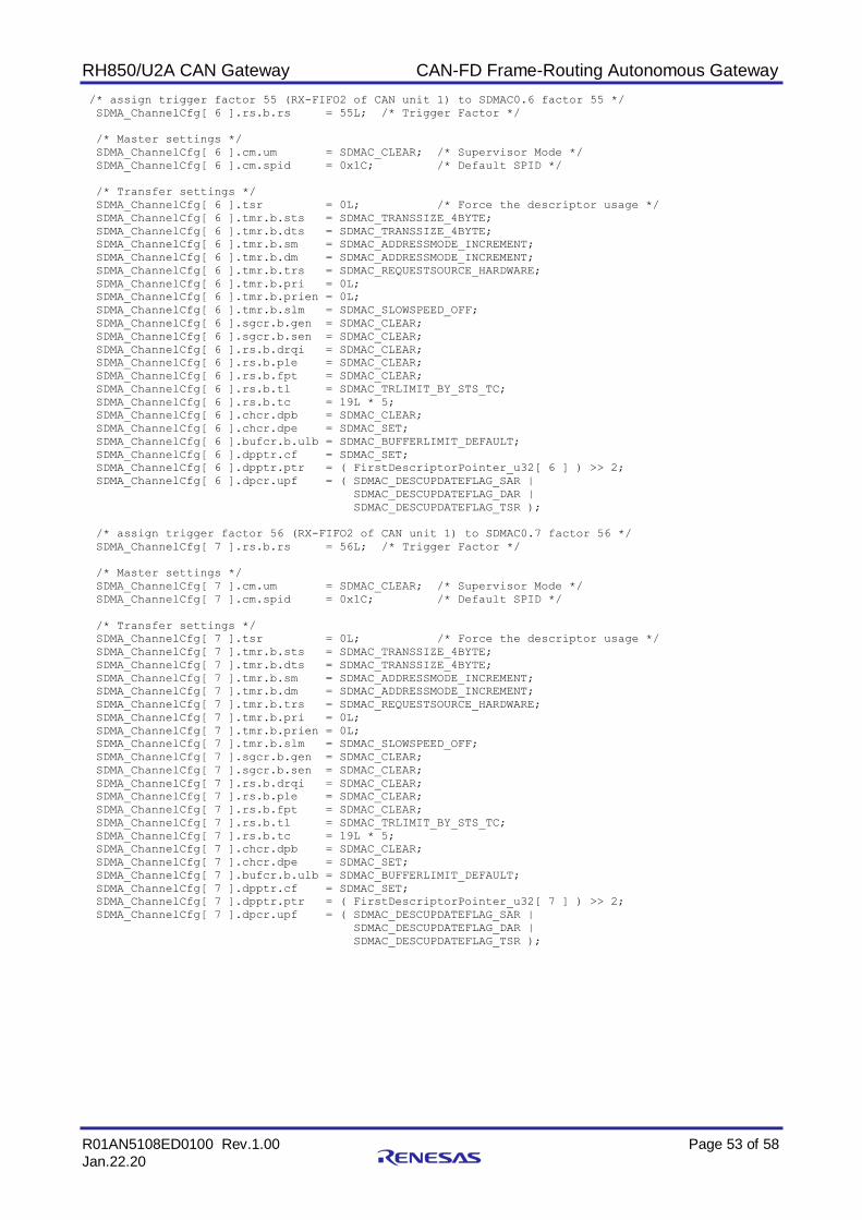
RH850/U2A CAN Gateway CAN-FD Frame-Routing Autonomous Gateway
R01AN5108ED0100 Rev.1.00 Page 53 of 58
Jan.22.20
/* assign trigger factor 55 (RX-FIFO2 of CAN unit 1) to SDMAC0.6 factor 55 */
SDMA_ChannelCfg[ 6 ].rs.b.rs = 55L; /* Trigger Factor */
/* Master settings */
SDMA_ChannelCfg[ 6 ].cm.um = SDMAC_CLEAR; /* Supervisor Mode */
SDMA_ChannelCfg[ 6 ].cm.spid = 0x1C; /* Default SPID */
/* Transfer settings */
SDMA_ChannelCfg[ 6 ].tsr = 0L; /* Force the descriptor usage */
SDMA_ChannelCfg[ 6 ].tmr.b.sts = SDMAC_TRANSSIZE_4BYTE;
SDMA_ChannelCfg[ 6 ].tmr.b.dts = SDMAC_TRANSSIZE_4BYTE;
SDMA_ChannelCfg[ 6 ].tmr.b.sm = SDMAC_ADDRESSMODE_INCREMENT;
SDMA_ChannelCfg[ 6 ].tmr.b.dm = SDMAC_ADDRESSMODE_INCREMENT;
SDMA_ChannelCfg[ 6 ].tmr.b.trs = SDMAC_REQUESTSOURCE_HARDWARE;
SDMA_ChannelCfg[ 6 ].tmr.b.pri = 0L;
SDMA_ChannelCfg[ 6 ].tmr.b.prien = 0L;
SDMA_ChannelCfg[ 6 ].tmr.b.slm = SDMAC_SLOWSPEED_OFF;
SDMA_ChannelCfg[ 6 ].sgcr.b.gen = SDMAC_CLEAR;
SDMA_ChannelCfg[ 6 ].sgcr.b.sen = SDMAC_CLEAR;
SDMA_ChannelCfg[ 6 ].rs.b.drqi = SDMAC_CLEAR;
SDMA_ChannelCfg[ 6 ].rs.b.ple = SDMAC_CLEAR;
SDMA_ChannelCfg[ 6 ].rs.b.fpt = SDMAC_CLEAR;
SDMA_ChannelCfg[ 6 ].rs.b.tl = SDMAC_TRLIMIT_BY_STS_TC;
SDMA_ChannelCfg[ 6 ].rs.b.tc = 19L * 5;
SDMA_ChannelCfg[ 6 ].chcr.dpb = SDMAC_CLEAR;
SDMA_ChannelCfg[ 6 ].chcr.dpe = SDMAC_SET;
SDMA_ChannelCfg[ 6 ].bufcr.b.ulb = SDMAC_BUFFERLIMIT_DEFAULT;
SDMA_ChannelCfg[ 6 ].dpptr.cf = SDMAC_SET;
SDMA_ChannelCfg[ 6 ].dpptr.ptr = ( FirstDescriptorPointer_u32[ 6 ] ) >> 2;
SDMA_ChannelCfg[ 6 ].dpcr.upf = ( SDMAC_DESCUPDATEFLAG_SAR |
SDMAC_DESCUPDATEFLAG_DAR |
SDMAC_DESCUPDATEFLAG_TSR );
/* assign trigger factor 56 (RX-FIFO2 of CAN unit 1) to SDMAC0.7 factor 56 */
SDMA_ChannelCfg[ 7 ].rs.b.rs = 56L; /* Trigger Factor */
/* Master settings */
SDMA_ChannelCfg[ 7 ].cm.um = SDMAC_CLEAR; /* Supervisor Mode */
SDMA_ChannelCfg[ 7 ].cm.spid = 0x1C; /* Default SPID */
/* Transfer settings */
SDMA_ChannelCfg[ 7 ].tsr = 0L; /* Force the descriptor usage */
SDMA_ChannelCfg[ 7 ].tmr.b.sts = SDMAC_TRANSSIZE_4BYTE;
SDMA_ChannelCfg[ 7 ].tmr.b.dts = SDMAC_TRANSSIZE_4BYTE;
SDMA_ChannelCfg[ 7 ].tmr.b.sm = SDMAC_ADDRESSMODE_INCREMENT;
SDMA_ChannelCfg[ 7 ].tmr.b.dm = SDMAC_ADDRESSMODE_INCREMENT;
SDMA_ChannelCfg[ 7 ].tmr.b.trs = SDMAC_REQUESTSOURCE_HARDWARE;
SDMA_ChannelCfg[ 7 ].tmr.b.pri = 0L;
SDMA_ChannelCfg[ 7 ].tmr.b.prien = 0L;
SDMA_ChannelCfg[ 7 ].tmr.b.slm = SDMAC_SLOWSPEED_OFF;
SDMA_ChannelCfg[ 7 ].sgcr.b.gen = SDMAC_CLEAR;
SDMA_ChannelCfg[ 7 ].sgcr.b.sen = SDMAC_CLEAR;
SDMA_ChannelCfg[ 7 ].rs.b.drqi = SDMAC_CLEAR;
SDMA_ChannelCfg[ 7 ].rs.b.ple = SDMAC_CLEAR;
SDMA_ChannelCfg[ 7 ].rs.b.fpt = SDMAC_CLEAR;
SDMA_ChannelCfg[ 7 ].rs.b.tl = SDMAC_TRLIMIT_BY_STS_TC;
SDMA_ChannelCfg[ 7 ].rs.b.tc = 19L * 5;
SDMA_ChannelCfg[ 7 ].chcr.dpb = SDMAC_CLEAR;
SDMA_ChannelCfg[ 7 ].chcr.dpe = SDMAC_SET;
SDMA_ChannelCfg[ 7 ].bufcr.b.ulb = SDMAC_BUFFERLIMIT_DEFAULT;
SDMA_ChannelCfg[ 7 ].dpptr.cf = SDMAC_SET;
SDMA_ChannelCfg[ 7 ].dpptr.ptr = ( FirstDescriptorPointer_u32[ 7 ] ) >> 2;
SDMA_ChannelCfg[ 7 ].dpcr.upf = ( SDMAC_DESCUPDATEFLAG_SAR |
SDMAC_DESCUPDATEFLAG_DAR |
SDMAC_DESCUPDATEFLAG_TSR );

RH850/U2A CAN Gateway CAN-FD Frame-Routing Autonomous Gateway
R01AN5108ED0100 Rev.1.00 Page 54 of 58
Jan.22.20
for( Unit_u08 = 0;
Unit_u08 < SDMA_A_UNITS;
Unit_u08++ )
{
Status_bit &= SDMAC_Reset( Unit_u08,
SDMAC_GLOBAL,
SDMAC_PRIOMODE_RNDROBIN );
for( Channel_u08 = 0;
Channel_u08 < SDMA_A_CHANNELS;
Channel_u08++ )
{
/* assign trigger group 0 (RX-FIFO of CAN units) to SDMAC0 channels */
Status_bit &= SDMAC_HWTriggerChannel( Unit_u08,
Channel_u08,
0, /* Trigger Group 0 */
SDMA_ChannelCfg[ Channel_u08 ].rs.b.rs );
/* Configure and Enable the SDMAC Channels */
Status_bit &= SDMAC_ConfigureChannel( Unit_u08,
Channel_u08,
&SDMA_ChannelCfg[ Channel_u08 ] );
Status_bit &= SDMAC_EnableChannel( Unit_u08,
Channel_u08 );
}
}
return( Status_bit );
}

RH850/U2A CAN Gateway CAN-FD Frame-Routing Autonomous Gateway
R01AN5108ED0100 Rev.1.00 Page 55 of 58
Jan.22.20
/*
+------------------------------------------------------------------------------+
| GW_Startup |
+------------------------------------------------------------------------------+
| |
| Startup of Gateway: Initializations and Modes |
| |
+------------------------------------------------------------------------------+
*/
bit GW_Startup( void )
{
u08 Machine_u08;
u08 Unit_u08;
u08 Channel_u08;
u08 PreviousUnit_u08 = RSCFD_GLOBAL;
bit Status_bit = RSCFD_OK;
for( Machine_u08 = 0;
Machine_u08 < CAN_A_MACHINES;
Machine_u08++ )
{
Unit_u08 = CAN_A_UNIT( Machine_u08 );
Channel_u08 = CAN_A_CHANNEL( Machine_u08 );
Status_bit &= RSCFD_PortEnable( Unit_u08,
Channel_u08 );
if( PreviousUnit_u08 != Unit_u08 )
{
PreviousUnit_u08 = Unit_u08;
Status_bit &= RSCFD_Stop( Unit_u08,
RSCFD_GLOBAL,
RSCFD_OPMODE_RESET );
Status_bit &= RSCFD_SetGlobalConfiguration( Unit_u08,
&RSCFD_A_GCFG_GW );
Status_bit &= RSCFD_SetGlobalFIFOConfiguration( Unit_u08,
&RSCFD_A_GCFG_GW );
Status_bit &= RSCFD_CreateInterrupt( Unit_u08,
RSCFD_GLOBAL,
RSCFD_INT_RXF1,
RSCFD_INTENABLEDEFAULT,
HW_Gateway_Processing_Exit );
Status_bit &= RSCFD_CreateInterrupt( Unit_u08,
RSCFD_GLOBAL,
RSCFD_INT_GERR,
RSCFD_INTENABLEDEFAULT,
HW_Gateway_Error );
}
}

RH850/U2A CAN Gateway CAN-FD Frame-Routing Autonomous Gateway
R01AN5108ED0100 Rev.1.00 Page 56 of 58
Jan.22.20
PreviousUnit_u08 = RSCFD_GLOBAL;
for( Machine_u08 = 0;
Machine_u08 < CAN_A_MACHINES;
Machine_u08++ )
{
Unit_u08 = CAN_A_UNIT( Machine_u08 );
Channel_u08 = CAN_A_CHANNEL( Machine_u08 );
Status_bit &= RSCFD_Start( Unit_u08, /* Perform global activation */
Channel_u08,
RSCFD_OPMODE_RESET, /* Channel Reset */
RSCFD_CLEAR,
RSCFD_CLEAR );
if( PreviousUnit_u08 != Unit_u08 )
{
PreviousUnit_u08 = Unit_u08;
Status_bit &= RSCFD_SetGlobalConfiguration( Unit_u08,
&RSCFD_A_GCFG_GW );
Status_bit &= RSCFD_EnableRXFIFO( Unit_u08,
0,
RSCFD_SET );
Status_bit &= RSCFD_EnableRXFIFO( Unit_u08,
1,
RSCFD_SET );
Status_bit &= RSCFD_EnableRXFIFO( Unit_u08,
2,
RSCFD_SET );
Status_bit &= RSCFD_EnableRXFIFO( Unit_u08,
3,
RSCFD_SET );
Status_bit &= RSCFD_EnableRXFIFO( Unit_u08,
4,
RSCFD_SET );
}
}
return( Status_bit );
}

RH850/U2A CAN Gateway CAN-FD Frame-Routing Autonomous Gateway
R01AN5108ED0100 Rev.1.00 Page 57 of 58
Jan.22.20
/*
+------------------------------------------------------------------------------+
| main |
+------------------------------------------------------------------------------+
| |
| Main Entry of Gateway after RESET |
| |
+------------------------------------------------------------------------------+
*/
void main( void )
{
bit Status_bit;
Status_bit = GW_Startup( );
Status_bit &= GW_AssignRules( );
ASMN_EICOMMAND;
Status_bit &= GW_ActivateSDMA( );
Status_bit &= GW_ActivateChannels( );
while( ( !ExitFlag_bit ) && ( Status_bit ) )
{
__asm( "halt" );
}
}

RH850/U2A CAN Gateway CAN-FD Frame-Routing Autonomous Gateway
R01AN5108ED0100 Rev.1.00 Page 58 of 58
Jan.22.20
Revision History
Rev. Date
Description
Page Summary
01.00 22-JAN-2020 all Initial creation.

General Precautions in the Handling of Microprocessing Unit and Microcontroller Unit Products
The following usage notes are applicable to all Microprocessing unit and Microcontroller unit products from Renesas. For detailed usage notes on the products covered by this document, refer to the relevant sections of the document as well as any technical updates that have been issued for the products.
1. Precaution against Electrostatic Discharge (ESD)
A strong electrical field, when exposed to a CMOS device, can cause destruction of the gate oxide and ultimately degrade the device operation. Steps
must be taken to stop the generation of static electricity as much as possible, and quickly dissipate it when it occurs. Environmental control must be
adequate. When it is dry, a humidifier should be used. This is recommended to avoid using insulators that can easily build up static electricity.
Semiconductor devices must be stored and transported in an anti-static container, static shielding bag or conductive material. All test and
measurement tools including work benches and floors must be grounded. The operator must also be grounded using a wrist strap. Semiconductor
devices must not be touched with bare hands. Similar precautions must be taken for printed circuit boards with mounted semiconductor devices.
2. Processing at power-on
The state of the product is undefined at the time when power is supplied. The states of internal circuits in the LSI are indeterminate and the states of
register settings and pins are undefined at the time when power is supplied. In a finished product where the reset signal is applied to the external reset
pin, the states of pins are not guaranteed from the time when power is supplied until the reset process is completed. In a similar way, the states of pins
in a product that is reset by an on-chip power-on reset function are not guaranteed from the time when power is supplied until the power reaches the
level at which resetting is specified.
3. Input of signal during power-off state
Do not input signals or an I/O pull-up power supply while the device is powered off. The current injection that results from input of such a signal or I/O
pull-up power supply may cause malfunction and the abnormal current that passes in the device at this time may cause degradation of internal
elements. Follow the guideline for input signal during power-off state as described in your product documentation.
4. Handling of unused pins
Handle unused pins in accordance with the directions given under handling of unused pins in the manual. The input pins of CMOS products are
generally in the high-impedance state. In operation with an unused pin in the open-circuit state, extra electromagnetic noise is induced in the vicinity of
the LSI, an associated shoot-through current flows internally, and malfunctions occur due to the false recognition of the pin state as an input signal
become possible.
5. Clock signals
After applying a reset, only release the reset line after the operating clock signal becomes stable. When switching the clock signal during program
execution, wait until the target clock signal is stabilized. When the clock signal is generated with an external resonator or from an external oscillator
during a reset, ensure that the reset line is only released after full stabilization of the clock signal. Additionally, when switching to a clock signal
produced with an external resonator or by an external oscillator while program execution is in progress, wait until the target clock signal is stable.
6. Voltage application waveform at input pin
Waveform distortion due to input noise or a reflected wave may cause malfunction. If the input of the CMOS device stays in the area between VIL
(Max.) and VIH (Min.) due to noise, for example, the device may malfunction. Take care to prevent chattering noise from entering the device when the
input level is fixed, and also in the transition period when the input level passes through the area between VIL (Max.) and VIH (Min.).
7. Prohibition of access to reserved addresses
Access to reserved addresses is prohibited. The reserved addresses are provided for possible future expansion of functions. Do not access these
addresses as the correct operation of the LSI is not guaranteed.
8. Differences between products
Before changing from one product to another, for example to a product with a different part number, confirm that the change will not lead to problems.
The characteristics of a microprocessing unit or microcontroller unit products in the same group but having a different part number might differ in terms
of internal memory capacity, layout pattern, and other factors, which can affect the ranges of electrical characteristics, such as characteristic values,
operating margins, immunity to noise, and amount of radiated noise. When changing to a product with a different part number, implement a system-
evaluation test for the given product.

© 2020 Renesas Electronics Corporation. All rights reserved.
Notice
1. Descriptions of circuits, software and other related information in this document are provided only to illustrate the operation of semiconductor products
and application examples. You are fully responsible for the incorporation or any other use of the circuits, software, and information in the design of your
product or system. Renesas Electronics disclaims any and all liability for any losses and damages incurred by you or third parties arising from the use
of these circuits, software, or information.
2. Renesas Electronics hereby expressly disclaims any warranties against and liability for infringement or any other claims involving patents, copyrights,
or other intellectual property rights of third parties, by or arising from the use of Renesas Electronics products or technical information described in this
document, including but not limited to, the product data, drawings, charts, programs, algorithms, and application examples.
3. No license, express, implied or otherwise, is granted hereby under any patents, copyrights or other intellectual property rights of Renesas Electronics
or others.
4. You shall not alter, modify, copy, or reverse engineer any Renesas Electronics product, whether in whole or in part. Renesas Electronics disclaims any
and all liability for any losses or damages incurred by you or third parties arising from such alteration, modification, copying or reverse engineering.
5. Renesas Electronics products are classified according to the following two quality grades: “Standard” and “High Quality”. The intended applications for
each Renesas Electronics product depends on the product’s quality grade, as indicated below.
"Standard": Computers; office equipment; communications equipment; test and measurement equipment; audio and visual equipment; home
electronic appliances; machine tools; personal electronic equipment; industrial robots; etc.
"High Quality": Transportation equipment (automobiles, trains, ships, etc.); traffic control (traffic lights); large-scale communication equipment; key
financial terminal systems; safety control equipment; etc.
Unless expressly designated as a high reliability product or a product for harsh environments in a Renesas Electronics data sheet or other Renesas
Electronics document, Renesas Electronics products are not intended or authorized for use in products or systems that may pose a direct threat to
human life or bodily injury (artificial life support devices or systems; surgical implantations; etc.), or may cause serious property damage (space
system; undersea repeaters; nuclear power control systems; aircraft control systems; key plant systems; military equipment; etc.). Renesas Electronics
disclaims any and all liability for any damages or losses incurred by you or any third parties arising from the use of any Renesas Electronics product
that is inconsistent with any Renesas Electronics data sheet, user’s manual or other Renesas Electronics document.
6. When using Renesas Electronics products, refer to the latest product information (data sheets, user’s manuals, application notes, “General Notes for
Handling and Using Semiconductor Devices” in the reliability handbook, etc.), and ensure that usage conditions are within the ranges specified by
Renesas Electronics with respect to maximum ratings, operating power supply voltage range, heat dissipation characteristics, installation, etc. Renesas
Electronics disclaims any and all liability for any malfunctions, failure or accident arising out of the use of Renesas Electronics products outside of such
specified ranges.
7. Although Renesas Electronics endeavors to improve the quality and reliability of Renesas Electronics products, semiconductor products have specific
characteristics, such as the occurrence of failure at a certain rate and malfunctions under certain use conditions. Unless designated as a high reliability
product or a product for harsh environments in a Renesas Electronics data sheet or other Renesas Electronics document, Renesas Electronics
products are not subject to radiation resistance design. You are responsible for implementing safety measures to guard against the possibility of bodily
injury, injury or damage caused by fire, and/or danger to the public in the event of a failure or malfunction of Renesas Electronics products, such as
safety design for hardware and software, including but not limited to redundancy, fire control and malfunction prevention, appropriate treatment for
aging degradation or any other appropriate measures. Because the evaluation of microcomputer software alone is very difficult and impractical, you are
responsible for evaluating the safety of the final products or systems manufactured by you.
8. Please contact a Renesas Electronics sales office for details as to environmental matters such as the environmental compatibility of each Renesas
Electronics product. You are responsible for carefully and sufficiently investigating applicable laws and regulations that regulate the inclusion or use of
controlled substances, including without limitation, the EU RoHS Directive, and using Renesas Electronics products in compliance with all these
applicable laws and regulations. Renesas Electronics disclaims any and all liability for damages or losses occurring as a result of your noncompliance
with applicable laws and regulations.
9. Renesas Electronics products and technologies shall not be used for or incorporated into any products or systems whose manufacture, use, or sale is
prohibited under any applicable domestic or foreign laws or regulations. You shall comply with any applicable export control laws and regulations
promulgated and administered by the governments of any countries asserting jurisdiction over the parties or transactions.
10. It is the responsibility of the buyer or distributor of Renesas Electronics products, or any other party who distributes, disposes of, or otherwise sells or
transfers the product to a third party, to notify such third party in advance of the contents and conditions set forth in this document.
11. This document shall not be reprinted, reproduced or duplicated in any form, in whole or in part, without prior written consent of Renesas Electronics.
12. Please contact a Renesas Electronics sales office if you have any questions regarding the information contained in this document or Renesas
Electronics products.
(Note1) “Renesas Electronics” as used in this document means Renesas Electronics Corporation and also includes its directly or indirectly controlled
subsidiaries.
(Note2) “Renesas Electronics product(s)” means any product developed or manufactured by or for Renesas Electronics.
(Rev.4.0-1 November 2017)
Corporate Headquarters Contact information TOYOSU FORESIA, 3-2-24 Toyosu,
Koto-ku, Tokyo 135-0061, Japan
www.renesas.com
For further information on a product, technology, the most up-to-date
version of a document, or your nearest sales office, please visit:
www.renesas.com/contact/.
Trademarks
Renesas and the Renesas logo are trademarks of Renesas Electronics
Corporation. All trademarks and registered trademarks are the property
of their respective owners.