Embed Size (px)
Citation preview
Rock HogDrilling Products
RH40R9HP
DTH HAMMER
OPERATION & MAINTENANCE MANUAL MANUAL No HW-49035
Web Site @ www.rockhog.com E-Mail Address: [email protected]
Manual No. HW-49035 Issued 2-1-15
Ph (717) 328-9808 Toll Free 1-888-7-ROCKHOG
FAX (717) 328-5010 EMAIL [email protected]
ii
Table of Contents
SECTION 1. GENERAL INFORMATION .............................................................................. 2
1.1 Description .................................................................................................................................. 2
1.3 Air Supply .................................................................................................................................... 2
1.4 Unpacking a New Hammer ......................................................................................................... 2
SECTION 2. HAMMER OPERATION.................................................................................... 3
2.1 Lubrication of Internal Parts ...................................................................................................... 3
2.2 Lubrication of Threaded Connections ......................................................................................... 3
2.3 Hole Cleaning .............................................................................................................................. 3
2.4 Setting the Choke ....................................................................................................................... 3
2.5 Effect of Elevation ....................................................................................................................... 4
2.6 Water Injection ........................................................................................................................... 4
2.7 Drilling Under Water ................................................................................................................... 4
2.8 Drill Pipe/Changing Pipe............................................................................................................. 4
2.9 Function of Parts ......................................................................................................................... 4
2.10 Installing the Bit ....................................................................................................................... 5
2.11 Connect the Hammer ................................................................................................................ 5
2.12 Drilling ...................................................................................................................................... 5
2.13 The Drill Bit ............................................................................................................................... 6
2.14 Breaking Threads Loose ............................................................................................................ 6
2.15 Monitoring ................................................................................................................................. 6
2.16 Storage ...................................................................................................................................... 7
Manual No. HW-49035 Issued 2-1-15
Ph (717) 328-9808 Toll Free 1-888-7-ROCKHOG
FAX (717) 328-5010 EMAIL [email protected]
iii
SECTION 3. MAINTENANCE ............................................................................................... 8
3.1 Schedule ...................................................................................................................................... 8
3.2 Disassembly ................................................................................................................................ 8
3.3 Inspection ................................................................................................................................... 9
3.4 Assembly ................................................................................................................................... 11
SECTION 4. PARTS BREAKDOWN ................................................................................... 13
Exploded View, model RH40R9HP .................................................................................................. 13
Assembled View .............................................................................................................................. 13
Part List, Model RH40R9HP ............................................................................................................ 14
SECTION 5. TROUBLE SHOOTING................................................................................... 15
Manual No. HW-49035 Issued 2-1-15
Ph (717) 328-9808 Toll Free 1-888-7-ROCKHOG
FAX (717) 328-5010 EMAIL [email protected]
2
Section 1. General Information
1.1 Description The RH40HP hammer is a valveless pneumatic
percussion hammer for drilling in all rock formations. It
is designed for a wide range of applications including
water wells, blast holes, and construction when drilling 4” to 5-1/8” holes. The 40HP incorporates one moving
part, the piston, making the hammer very reliable. The HP hammer is designed with a more efficient air cycle
for improved performance. All external parts are
hardened to resist wear while all critical internal parts are also hardened for maximum service life. The simple
design also makes the hammer easy to maintain and service.
1.2 SPECIFICATIONS English Metric
Outside Dia 3.63 in 92.2 mm
Overall Length
Without Bit43.6 in 1107 mm
Operating Length
API shoulder
to Bit Face
43.7 in 1110 mm
Total Weight 86 lbs 38 kg
Bore Size 2.95 in 75 mm
Piston Weight 19 lbs 8.5 kg
Drillpipe Connect
Wrench Flats 3 in 76 mm
Hole Size Range
102 mm to 127 mm
Bit Shank Required 340
Minimum Air Volume
Required150 cfm 4.5 cmm
Operating Pressure 500 psi 34 bar
2-3/8 Reg API Pin Upothers available upon request
4 in to 5 in
1.3 Air Supply A minimum of 150 cfm is recommended to be
supplied to the hammer up to air supplies of 900 cfm. The hammer will function on lower supplies but the
penetration rate will be very slow. For the fastest
possible penetration, the hammer should be operated at the highest obtainable pressure for the given air
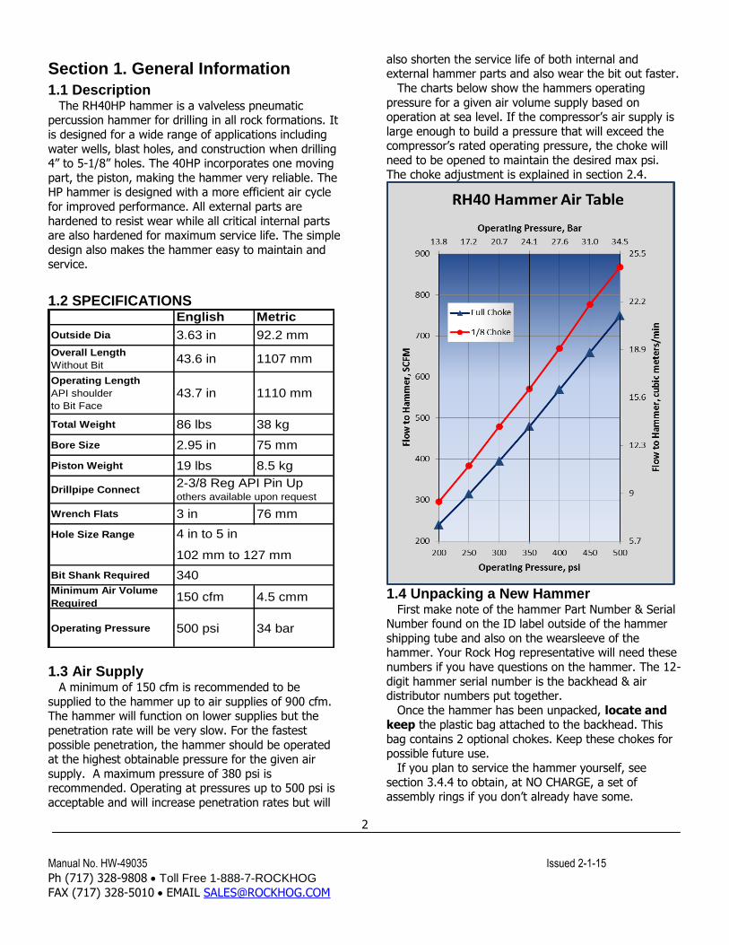
supply. A maximum pressure of 380 psi is recommended. Operating at pressures up to 500 psi is
acceptable and will increase penetration rates but will
also shorten the service life of both internal and external hammer parts and also wear the bit out faster.
The charts below show the hammers operating
pressure for a given air volume supply based on operation at sea level. If the compressor’s air supply is
large enough to build a pressure that will exceed the compressor’s rated operating pressure, the choke will
need to be opened to maintain the desired max psi. The choke adjustment is explained in section 2.4.
1.4 Unpacking a New Hammer
First make note of the hammer Part Number & Serial Number found on the ID label outside of the hammer
shipping tube and also on the wearsleeve of the hammer. Your Rock Hog representative will need these
numbers if you have questions on the hammer. The 12-
digit hammer serial number is the backhead & air distributor numbers put together.
Once the hammer has been unpacked, locate and keep the plastic bag attached to the backhead. This
bag contains 2 optional chokes. Keep these chokes for
possible future use. If you plan to service the hammer yourself, see
section 3.4.4 to obtain, at NO CHARGE, a set of assembly rings if you don’t already have some.
Manual No. HW-49035 Issued 2-1-15
Ph (717) 328-9808 Toll Free 1-888-7-ROCKHOG
FAX (717) 328-5010 EMAIL [email protected]
3
Section 2. Hammer Operation
2.1 Lubrication of Internal Parts The hammer must have a constant and
adequate supply of oil to prevent part wear,
corrosion, and failure. Rock Hog recommends Mobil
ALMO series, Chevron VISTAC series, or an equivalent grade. Contact your local lubricant representative for
the proper grade to use for your drilling environment and temperatures.
Make sure the oil injector is filled and working
properly. Always verify that there is oil coming through the drill string, DO NOT RUN THE HAMMER
WITHOUT CONSTANT OIL INJECTION! THE HP HAMMERS REQUIRE MORE OIL THAN THEIR
PREDECESSORS.
Set the system to inject 1.3 pints per hour for every 300 cfm of air supply. Example, if the supply is 950
cfm, inject 950/300x1.3 = 4.2 pints per hour. Again this is more oil than the older models.
Oil Properties
Mobil ALMO Grade 525 529 532
Chevron VISTAC Grade ISO46 ISO 150 ISO 320
When to use winter summersummer, production
drilling
ISO viscosity grade 46 150 320SAE viscosity grade 20W-20 30 50Viscosity
cSt @ 40oC,
ASTM D 44544 144 310
cSt @ 100oC 6 14 22
SUS @ 100oF,
ASTM D 2161228 755 1660
SUS @ 210oF 48 75 112
Flash PointoC 210 220 220
oF 410 450 450
2.2 Lubrication of Threaded Connections All threaded connection must be coated with a no-gall
grease. Both the backhead and chuck thread into the wear sleeve. The hammer is shipped with grease on
both of the connections. All drill pipe connections must also be coated. When applying grease, be careful
not to put grease where it will enter the air
stream. The grease will not blow through the hammer but stick to the internal parts. Excessive
grease in the hammer will close the airways and stop the hammer.
Use a high performance copper based grease. Rock Hog recommends Bestolife brand, type Copper Rock
or an equivalent.
2.3 Hole Cleaning For proper hole cleaning, verify that an adequate up-
hole air velocity can be obtained. An annular velocity of 3000 feet-per-minute or more is required. Use this
formula to check what the velocity will be: (183) x (supply CFM) Velocity (fpm) = ------------------------------------- (bit size)
2 - (drill pipe size)
2
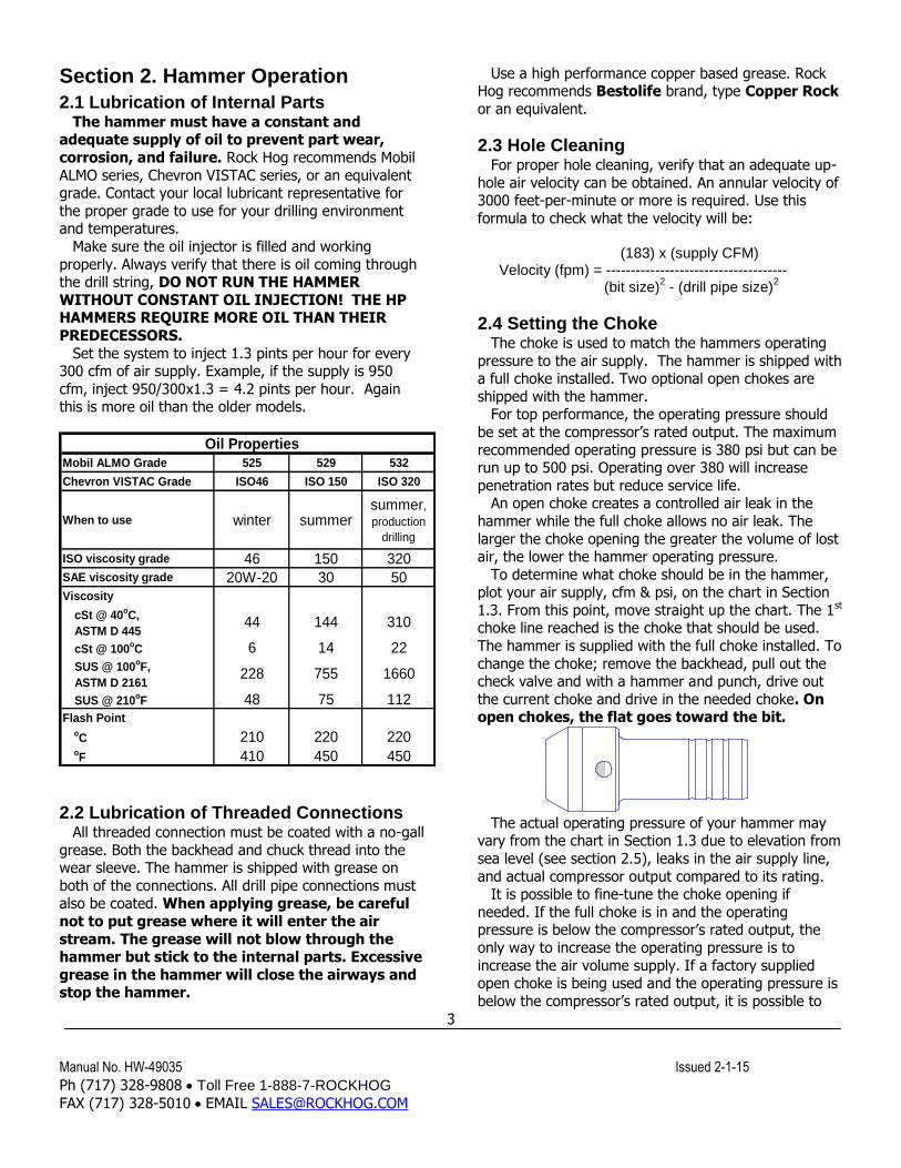
2.4 Setting the Choke The choke is used to match the hammers operating
pressure to the air supply. The hammer is shipped with a full choke installed. Two optional open chokes are
shipped with the hammer. For top performance, the operating pressure should
be set at the compressor’s rated output. The maximum
recommended operating pressure is 380 psi but can be run up to 500 psi. Operating over 380 will increase
penetration rates but reduce service life. An open choke creates a controlled air leak in the
hammer while the full choke allows no air leak. The
larger the choke opening the greater the volume of lost air, the lower the hammer operating pressure.
To determine what choke should be in the hammer, plot your air supply, cfm & psi, on the chart in Section
1.3. From this point, move straight up the chart. The 1st choke line reached is the choke that should be used.
The hammer is supplied with the full choke installed. To
change the choke; remove the backhead, pull out the check valve and with a hammer and punch, drive out
the current choke and drive in the needed choke. On open chokes, the flat goes toward the bit.
The actual operating pressure of your hammer may
vary from the chart in Section 1.3 due to elevation from
sea level (see section 2.5), leaks in the air supply line,
and actual compressor output compared to its rating. It is possible to fine-tune the choke opening if
needed. If the full choke is in and the operating pressure is below the compressor’s rated output, the
only way to increase the operating pressure is to
increase the air volume supply. If a factory supplied open choke is being used and the operating pressure is
below the compressor’s rated output, it is possible to
Manual No. HW-49035 Issued 2-1-15
Ph (717) 328-9808 Toll Free 1-888-7-ROCKHOG
FAX (717) 328-5010 EMAIL [email protected]
4
bring the operating pressure up to the rating by taking the full choke and making a flat on it that is smaller
than the current open choke.
If the hammer is used on an air supply of 800 cfm or higher, it may be necessary to remove the choke
completely to allow enough air to by-pass through and maintain the proper operating pressure.
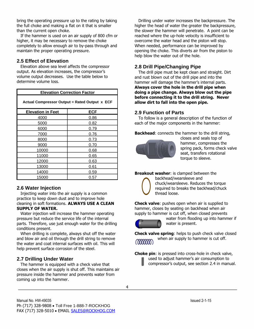
2.5 Effect of Elevation Elevation above sea level affects the compressor
output. As elevation increases, the compressor’s
volume output decreases. Use the table below to determine volume loss.
Elevation in Feet ECF
4000 0.86
5000 0.82
6000 0.79
7000 0.76
8000 0.73
9000 0.70
10000 0.68
11000 0.65
12000 0.63
13000 0.61
14000 0.59
15000 0.57
Elevation Correction Factor
Actual Compressor Output = Rated Output x ECF
2.6 Water Injection Injecting water into the air supply is a common
practice to keep down dust and to improve hole cleaning in soft formations. ALWAYS USE A CLEAN
SUPPLY OF WATER. Water injection will increase the hammer operating
pressure but reduce the service life of the internal
parts. Therefore, use just enough water for the drilling conditions present.
When drilling is complete, always shut off the water and blow air and oil through the drill string to remove
the water and coat internal surfaces with oil. This will help prevent surface corrosion of the steel.
2.7 Drilling Under Water The hammer is equipped with a check valve that
closes when the air supply is shut off. This maintains air
pressure inside the hammer and prevents water from coming up into the hammer.
Drilling under water increases the backpressure. The higher the head of water the greater the backpressure,
the slower the hammer will penetrate. A point can be
reached where the up-hole velocity is insufficient to overcome the water head and the piston will stop.
When needed, performance can be improved by opening the choke. This diverts air from the piston to
help blow the water out of the hole.
2.8 Drill Pipe/Changing Pipe
The drill pipe must be kept clean and straight. Dirt
and rust blown out of the drill pipe and into the
hammer will damage the hammer’s internal parts. Always cover the hole in the drill pipe when
doing a pipe change. Always blow out the pipe before connecting it to the drill string. Never
allow dirt to fall into the open pipe.
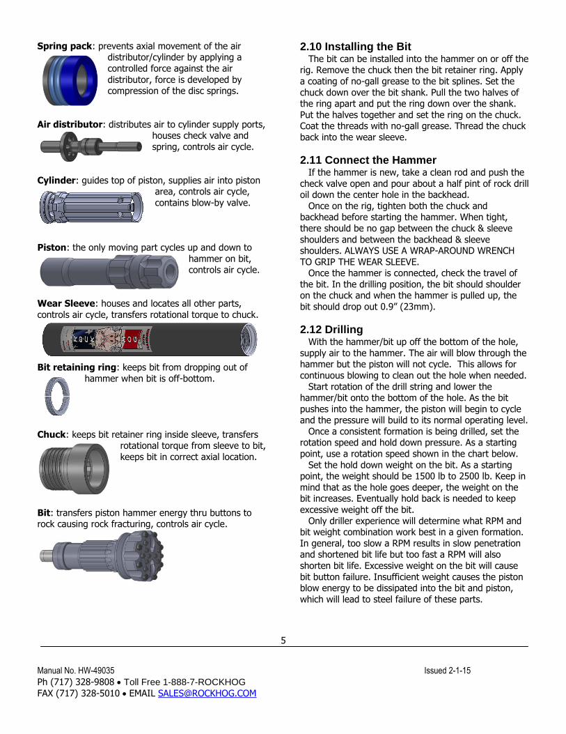
2.9 Function of Parts To follow is a general description of the function of
each of the major components in the hammer:
Backhead: connects the hammer to the drill string, closes and seals top of
hammer, compresses the
spring pack, forms check valve seat, transfers rotational
torque to sleeve.
Breakout washer: is clamped between the backhead/wearsleeve and
chuck/wearsleeve. Reduces the torque required to breaks the backhead/chuck
thread loose.
Check valve: pushes open when air is supplied to
hammer, closes by seating on backhead when air supply to hammer is cut off, when closed prevents
water from flooding up into hammer if water is present.
Check valve spring: helps to push check valve closed when air supply to hammer is cut off.
Choke pin: is pressed into cross-hole in check valve, used to adjust hammer’s air consumption to
compressor’s output, see section 2.4 in manual.
Manual No. HW-49035 Issued 2-1-15
Ph (717) 328-9808 Toll Free 1-888-7-ROCKHOG
FAX (717) 328-5010 EMAIL [email protected]
5
Spring pack: prevents axial movement of the air distributor/cylinder by applying a
controlled force against the air
distributor, force is developed by compression of the disc springs.
Air distributor: distributes air to cylinder supply ports, houses check valve and
spring, controls air cycle.
Cylinder: guides top of piston, supplies air into piston area, controls air cycle,
contains blow-by valve.
Piston: the only moving part cycles up and down to
hammer on bit, controls air cycle.
Wear Sleeve: houses and locates all other parts,
controls air cycle, transfers rotational torque to chuck.
Bit retaining ring: keeps bit from dropping out of
hammer when bit is off-bottom.
Chuck: keeps bit retainer ring inside sleeve, transfers rotational torque from sleeve to bit,
keeps bit in correct axial location.
Bit: transfers piston hammer energy thru buttons to rock causing rock fracturing, controls air cycle.
2.10 Installing the Bit The bit can be installed into the hammer on or off the
rig. Remove the chuck then the bit retainer ring. Apply
a coating of no-gall grease to the bit splines. Set the
chuck down over the bit shank. Pull the two halves of the ring apart and put the ring down over the shank.
Put the halves together and set the ring on the chuck. Coat the threads with no-gall grease. Thread the chuck
back into the wear sleeve.
2.11 Connect the Hammer If the hammer is new, take a clean rod and push the
check valve open and pour about a half pint of rock drill oil down the center hole in the backhead.
Once on the rig, tighten both the chuck and backhead before starting the hammer. When tight,
there should be no gap between the chuck & sleeve
shoulders and between the backhead & sleeve shoulders. ALWAYS USE A WRAP-AROUND WRENCH
TO GRIP THE WEAR SLEEVE. Once the hammer is connected, check the travel of
the bit. In the drilling position, the bit should shoulder on the chuck and when the hammer is pulled up, the
bit should drop out 0.9” (23mm).
2.12 Drilling With the hammer/bit up off the bottom of the hole,
supply air to the hammer. The air will blow through the hammer but the piston will not cycle. This allows for
continuous blowing to clean out the hole when needed.
Start rotation of the drill string and lower the hammer/bit onto the bottom of the hole. As the bit
pushes into the hammer, the piston will begin to cycle and the pressure will build to its normal operating level.
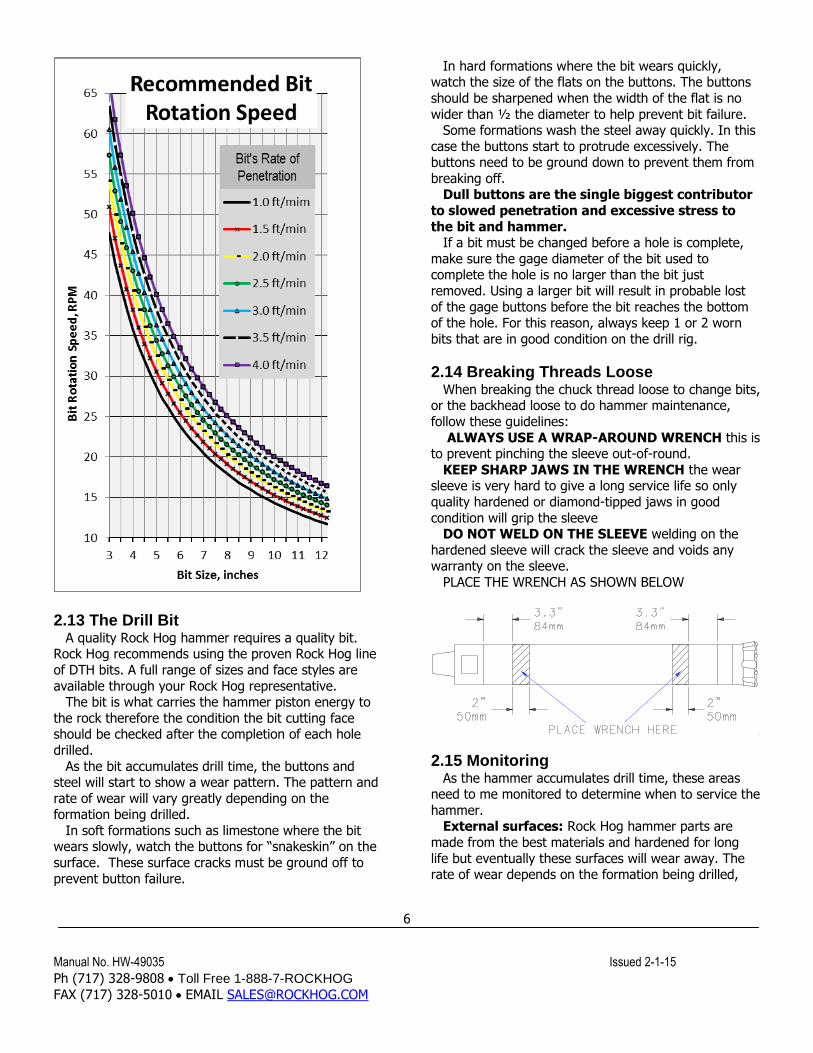
Once a consistent formation is being drilled, set the rotation speed and hold down pressure. As a starting
point, use a rotation speed shown in the chart below.
Set the hold down weight on the bit. As a starting point, the weight should be 1500 lb to 2500 lb. Keep in
mind that as the hole goes deeper, the weight on the bit increases. Eventually hold back is needed to keep
excessive weight off the bit.
Only driller experience will determine what RPM and bit weight combination work best in a given formation.
In general, too slow a RPM results in slow penetration and shortened bit life but too fast a RPM will also
shorten bit life. Excessive weight on the bit will cause
bit button failure. Insufficient weight causes the piston blow energy to be dissipated into the bit and piston,
which will lead to steel failure of these parts.
Manual No. HW-49035 Issued 2-1-15
Ph (717) 328-9808 Toll Free 1-888-7-ROCKHOG
FAX (717) 328-5010 EMAIL [email protected]
6
2.13 The Drill Bit
A quality Rock Hog hammer requires a quality bit. Rock Hog recommends using the proven Rock Hog line
of DTH bits. A full range of sizes and face styles are
available through your Rock Hog representative. The bit is what carries the hammer piston energy to
the rock therefore the condition the bit cutting face should be checked after the completion of each hole
drilled.
As the bit accumulates drill time, the buttons and steel will start to show a wear pattern. The pattern and
rate of wear will vary greatly depending on the formation being drilled.
In soft formations such as limestone where the bit wears slowly, watch the buttons for “snakeskin” on the
surface. These surface cracks must be ground off to
prevent button failure.
In hard formations where the bit wears quickly, watch the size of the flats on the buttons. The buttons
should be sharpened when the width of the flat is no
wider than ½ the diameter to help prevent bit failure. Some formations wash the steel away quickly. In this
case the buttons start to protrude excessively. The buttons need to be ground down to prevent them from
breaking off. Dull buttons are the single biggest contributor
to slowed penetration and excessive stress to
the bit and hammer. If a bit must be changed before a hole is complete,
make sure the gage diameter of the bit used to complete the hole is no larger than the bit just
removed. Using a larger bit will result in probable lost
of the gage buttons before the bit reaches the bottom of the hole. For this reason, always keep 1 or 2 worn
bits that are in good condition on the drill rig.
2.14 Breaking Threads Loose When breaking the chuck thread loose to change bits,
or the backhead loose to do hammer maintenance,
follow these guidelines:
ALWAYS USE A WRAP-AROUND WRENCH this is to prevent pinching the sleeve out-of-round.
KEEP SHARP JAWS IN THE WRENCH the wear sleeve is very hard to give a long service life so only
quality hardened or diamond-tipped jaws in good
condition will grip the sleeve DO NOT WELD ON THE SLEEVE welding on the
hardened sleeve will crack the sleeve and voids any warranty on the sleeve.
PLACE THE WRENCH AS SHOWN BELOW
2.15 Monitoring As the hammer accumulates drill time, these areas
need to me monitored to determine when to service the
hammer. External surfaces: Rock Hog hammer parts are
made from the best materials and hardened for long
life but eventually these surfaces will wear away. The rate of wear depends on the formation being drilled,
Manual No. HW-49035 Issued 2-1-15
Ph (717) 328-9808 Toll Free 1-888-7-ROCKHOG
FAX (717) 328-5010 EMAIL [email protected]
7
drilling speed and airflow. Make periodic checks to know what condition the parts are in.
Normally the chuck wears out first. Check the wall
thickness on the bit shoulder end. When it measures 5/16” (8mm) or less at any point, replace the chuck.
The service life of the chuck also heavily depends on the condition of the drill bit.
The wear sleeve will normally wear more on the chuck end. When the outside diameter reaches 3.53”
(89.7mm), flip the sleeve. Once either end has worn
down to a 3.36” (85.3mm) diameter, replace the sleeve. The service life of the sleeve also heavily
depends on the condition of the chuck. Chuck splines: check the condition of the chuck
splines each time the bit is removed. Do not put a
chuck with badly worn splines on a new bit. Shoulder Gap: a hand-tight backhead will not be
seated on the sleeve. Once the backhead is torqued down, this gap will close and the backhead will seat on
the sleeve. This clamps the internal parts to prevent part movement. Periodically check the gap between the
sleeve and hand-tight backhead. If the gap falls below
.08” (2.0mm), refer to Section 3.4-step 9. Operating pressure: this is the best way to know
what condition the internal parts are in. As internal parts wear, the operating pressure, and therefore the
penetration rate, will drop. Only the operator can say
when hammer performance has dropped below an acceptable level at which time the hammer must be
serviced. If the pressure goes up after the hammer has been in service for some time, this would indicate the
piston is sticking or the air passages inside the hammer
are becoming restricted.
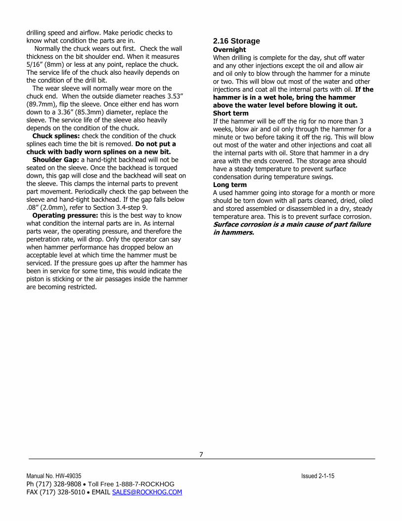
2.16 Storage Overnight
When drilling is complete for the day, shut off water
and any other injections except the oil and allow air and oil only to blow through the hammer for a minute
or two. This will blow out most of the water and other injections and coat all the internal parts with oil. If the
hammer is in a wet hole, bring the hammer above the water level before blowing it out.
Short term
If the hammer will be off the rig for no more than 3 weeks, blow air and oil only through the hammer for a
minute or two before taking it off the rig. This will blow out most of the water and other injections and coat all
the internal parts with oil. Store that hammer in a dry
area with the ends covered. The storage area should have a steady temperature to prevent surface
condensation during temperature swings. Long term
A used hammer going into storage for a month or more should be torn down with all parts cleaned, dried, oiled
and stored assembled or disassembled in a dry, steady
temperature area. This is to prevent surface corrosion. Surface corrosion is a main cause of part failure in hammers.
Manual No. HW-49035 Issued 2-1-15
Ph (717) 328-9808 Toll Free 1-888-7-ROCKHOG
FAX (717) 328-5010 EMAIL [email protected]
8
Section 3. Maintenance
3.1 Schedule If the need for service defined in Monitoring, section
2.14, is not reached first, follow these guidelines for
servicing the hammer:
When the hammer is operated to the parameters defined in section 2 in formations up to what is
considered “hard”, perform service every 25000 feet (7600 meters) of drilling.
When water injection & drilling foams are used
extensively, perform service every 18000 feet (5500 meters).
When drilling in “very hard” formations or when drilling under heavy mud, perform service every 10000
feet (3000 meters)
When injecting agents that are corrosive to metal, like potash to coat the hole wall, clean the hammer at
completion of the job. Use this as a starting point. Keep a log of
service done-vs.-footage drilled. This will help refine the service schedule to fit your operation.
3.2 Disassembly All parts are a sliding or clearance fit inside the
hammer but may be held by a retainer ring or may be
tight inside the hammer depending on the condition of the parts and the time period since the hammer was
last serviced.
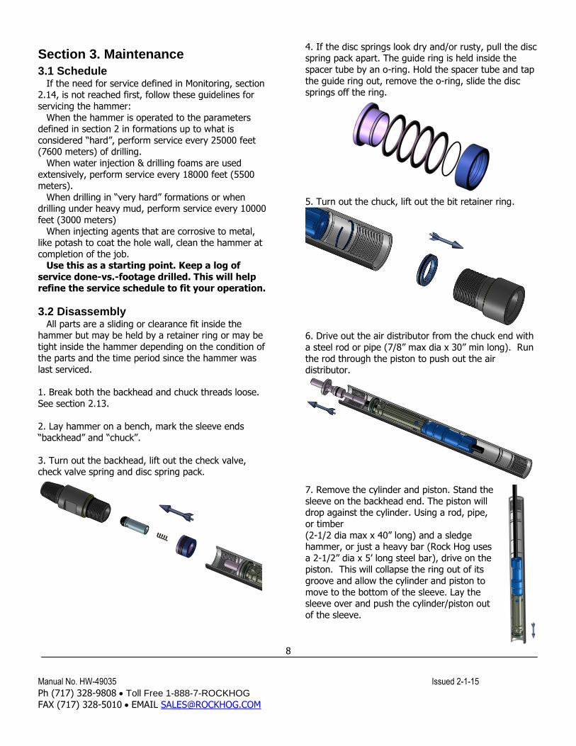
1. Break both the backhead and chuck threads loose.
See section 2.13.
2. Lay hammer on a bench, mark the sleeve ends “backhead” and “chuck”.
3. Turn out the backhead, lift out the check valve, check valve spring and disc spring pack.
4. If the disc springs look dry and/or rusty, pull the disc spring pack apart. The guide ring is held inside the
spacer tube by an o-ring. Hold the spacer tube and tap
the guide ring out, remove the o-ring, slide the disc springs off the ring.
5. Turn out the chuck, lift out the bit retainer ring.
6. Drive out the air distributor from the chuck end with
a steel rod or pipe (7/8” max dia x 30” min long). Run
the rod through the piston to push out the air distributor.
7. Remove the cylinder and piston. Stand the
sleeve on the backhead end. The piston will drop against the cylinder. Using a rod, pipe,
or timber
(2-1/2 dia max x 40” long) and a sledge hammer, or just a heavy bar (Rock Hog uses
a 2-1/2” dia x 5’ long steel bar), drive on the piston. This will collapse the ring out of its
groove and allow the cylinder and piston to
move to the bottom of the sleeve. Lay the sleeve over and push the cylinder/piston out
of the sleeve.
Manual No. HW-49035 Issued 2-1-15
Ph (717) 328-9808 Toll Free 1-888-7-ROCKHOG
FAX (717) 328-5010 EMAIL [email protected]
9
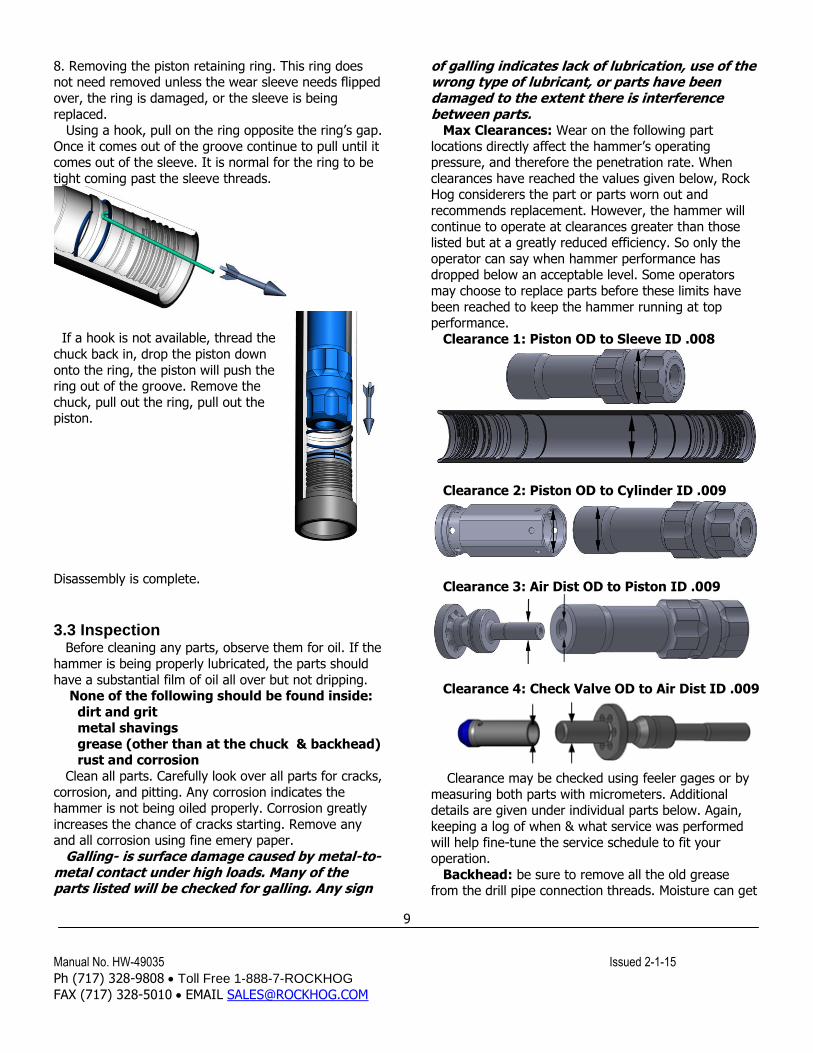
8. Removing the piston retaining ring. This ring does not need removed unless the wear sleeve needs flipped
over, the ring is damaged, or the sleeve is being
replaced. Using a hook, pull on the ring opposite the ring’s gap.
Once it comes out of the groove continue to pull until it comes out of the sleeve. It is normal for the ring to be
tight coming past the sleeve threads.
If a hook is not available, thread the
chuck back in, drop the piston down
onto the ring, the piston will push the ring out of the groove. Remove the
chuck, pull out the ring, pull out the piston.
Disassembly is complete.
3.3 Inspection
Before cleaning any parts, observe them for oil. If the
hammer is being properly lubricated, the parts should
have a substantial film of oil all over but not dripping. None of the following should be found inside:
dirt and grit metal shavings
grease (other than at the chuck & backhead) rust and corrosion
Clean all parts. Carefully look over all parts for cracks,
corrosion, and pitting. Any corrosion indicates the hammer is not being oiled properly. Corrosion greatly
increases the chance of cracks starting. Remove any and all corrosion using fine emery paper.
Galling- is surface damage caused by metal-to-metal contact under high loads. Many of the parts listed will be checked for galling. Any sign
of galling indicates lack of lubrication, use of the wrong type of lubricant, or parts have been damaged to the extent there is interference between parts.
Max Clearances: Wear on the following part
locations directly affect the hammer’s operating pressure, and therefore the penetration rate. When
clearances have reached the values given below, Rock Hog considerers the part or parts worn out and
recommends replacement. However, the hammer will
continue to operate at clearances greater than those listed but at a greatly reduced efficiency. So only the
operator can say when hammer performance has dropped below an acceptable level. Some operators
may choose to replace parts before these limits have
been reached to keep the hammer running at top performance.
Clearance 1: Piston OD to Sleeve ID .008
Clearance 2: Piston OD to Cylinder ID .009
Clearance 3: Air Dist OD to Piston ID .009
Clearance 4: Check Valve OD to Air Dist ID .009
Clearance may be checked using feeler gages or by
measuring both parts with micrometers. Additional details are given under individual parts below. Again,
keeping a log of when & what service was performed
will help fine-tune the service schedule to fit your operation.
Backhead: be sure to remove all the old grease from the drill pipe connection threads. Moisture can get
Manual No. HW-49035 Issued 2-1-15
Ph (717) 328-9808 Toll Free 1-888-7-ROCKHOG
FAX (717) 328-5010 EMAIL [email protected]
10
trapped under the grease and corrode the surface. This also allows for a visual check of wear on the threads.
Compare the worn threads to a new thread. If 50% of
the thread form is worn away, replace the backhead. Check the condition of the o-ring. If it is cracked, cut,
or brittle, replace it. Check the large threads for galling. Polish out any
damaged areas. The outside of the backhead will wear away.
This wear is not detrimental to the function of
the hammer but will eventually allow the drill pipe to wear away. Replace the backhead if it is
no longer protecting the drill pipe. Check Valve: check the condition of the rubber top.
If the surface is degraded, replace the check valve. If
the clearance with the air distributor bore is greater than .009” (.23mm), replace the check valve.
Check Valve Spring: the outside of the spring will be worn on one side about mid-length. If the wire
diameter has been reduced by more than 30%, replace the spring.
Dics Spring Pack: Replace any parts that are
cracked or damaged. In this case, the o-ring is not a seal but a retainer. Replace the o-ring if it no longer
holds the pack together. If there is any rust on the disc springs, remove all the rust and put a coat of oil on the
springs. Look for wear on the faces of the ring, spacer,
and springs. As the faces wear, there is less compression force created by the springs. This
compression is set by the compression gap described in section 3.4-step 9.
Air Distributor: make sure all the air holes are
clear. Check the clearance of the stem end with the back bore in the piston. If it exceeds .009” (.23mm)
replace the air distributor. Check the condition of the o-ring. If it is cracked, cut,
or brittle, replace it. Cylinder: check the inside bore for galling with the
piston. Polish out any surface damage.
Check the clearance of the bore with the top diameter of the piston. If it exceeds .009” (.23mm),
replace the cylinder. Check the new cylinder to the used piston. If the clearance exceeds .006” (.15mm),
replace the piston also.
Check the faces on the retaining ring in the outside groove. If the faces have a heavy step worn in them,
cut off the ring and put on a new ring. Piston: check the (2) outside guide diameters and
top bore for galling and burning. Polish out any minor damage found on the surfaces.
Any black areas on the surface indicate the piston
was rubbing and over heating. Surface heating is very detrimental to the piston. In most cases, if the surface
is black, that surface will also be covered with cracks. Replace the piston if it has excessive surface cracks.
If the wear sleeve has not been previously flipped,
check the clearance of the piston’s big diameter with the sleeve bore where the cylinder sits. If it exceeds
.006” (.15mm), replace the piston. Check the new piston to the sleeve bore on the chuck end. If the
clearance exceeds .006” (.15mm), flip the wear sleeve at assembly (note: normally sleeve external wear
determines when the sleeve gets flipped).
If the sleeve has been previously flipped, check the clearance of the big diameter with the sleeve bore
where the piston runs. If it exceeds .008” (.20mm), replace the sleeve. Check the piston to the new sleeve
bore. If the clearance exceeds .006” (.15mm), replace
the piston. Check the strike face for chipping and pitting.
Replace a piston with a badly damaged strike face. Note: the face can be reconditioned by removing
up to .04” (1mm) of material. Only a qualified machinist should do this. Reconditioned pistons
are not covered under warranty.
Remove any nicks, dents, burrs with fine emery paper or a fine honing stone.
Again look over the piston for any rust, corrosion, or pitting. All of these will lead to
cracks and failure of the piston.
Wear Sleeve: Check the outside diameter. The wear sleeve will normally wear more on the chuck end.
When any location on the outside diameter has reached 3.53” (89.7mm), flip the sleeve. Once any location
has worn down to a 3.36” (85.3mm) diameter,
replace the sleeve. Check the bore where the piston runs and the
threads for galling. Polish out any surface damage. Chuck: check the large threads for galling. Polish out
any damaged areas. Check the splines. The driving side will wear away. If
the form of the driving side still matches the bit, the
chuck is usable. If the form no longer matches the bit or more than ½ the spline thickness is worn away,
replace the chuck. Check the outside diameter for wear. If the wall
thickness on the bit shoulder end measures 5/16”
(8mm) or less at any point, replaced the chuck. Breakout Washers: These copper washers are on
the hammer when shipped. One between the backhead and sleeve, and one between the chuck and sleeve.
The washers are optional but they do reduce the torque required to break the threads loose. These rings do
disintegrate over time. During inspection there may be
just a portion of the ring remaining or no ring at all.
Manual No. HW-49035 Issued 2-1-15
Ph (717) 328-9808 Toll Free 1-888-7-ROCKHOG
FAX (717) 328-5010 EMAIL [email protected]
11
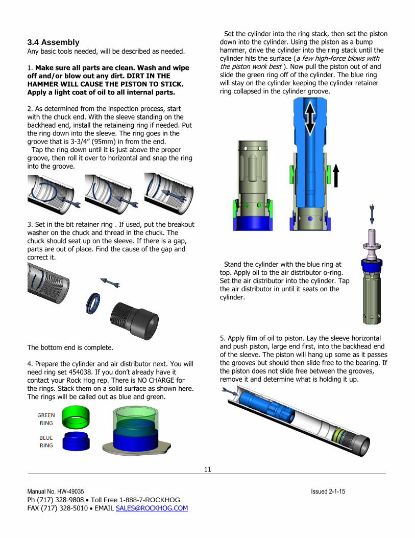
3.4 Assembly Any basic tools needed, will be described as needed.
1. Make sure all parts are clean. Wash and wipe off and/or blow out any dirt. DIRT IN THE
HAMMER WILL CAUSE THE PISTON TO STICK. Apply a light coat of oil to all internal parts.
2. As determined from the inspection process, start
with the chuck end. With the sleeve standing on the
backhead end, install the retaineing ring if needed. Put the ring down into the sleeve. The ring goes in the
groove that is 3-3/4” (95mm) in from the end. Tap the ring down until it is just above the proper
groove, then roll it over to horizontal and snap the ring
into the groove.
3. Set in the bit retainer ring . If used, put the breakout
washer on the chuck and thread in the chuck. The
chuck should seat up on the sleeve. If there is a gap, parts are out of place. Find the cause of the gap and
correct it.
The bottom end is complete.
4. Prepare the cylinder and air distributor next. You will
need ring set 454038. If you don’t already have it contact your Rock Hog rep. There is NO CHARGE for
the rings. Stack them on a solid surface as shown here.
The rings will be called out as blue and green.
Set the cylinder into the ring stack, then set the piston down into the cylinder. Using the piston as a bump
hammer, drive the cylinder into the ring stack until the
cylinder hits the surface (a few high-force blows with the piston work best ). Now pull the piston out of and
slide the green ring off of the cylinder. The blue ring will stay on the cylinder keeping the cylinder retainer
ring collapsed in the cylinder groove.
Stand the cylinder with the blue ring at
top. Apply oil to the air distributor o-ring.
Set the air distributor into the cylinder. Tap the air distributor in until it seats on the
cylinder.
5. Apply film of oil to piston. Lay the sleeve horizontal and push piston, large end first, into the backhead end
of the sleeve. The piston will hang up some as it passes the grooves but should then slide free to the bearing. If
the piston does not slide free between the grooves,
remove it and determine what is holding it up.
Manual No. HW-49035 Issued 2-1-15
Ph (717) 328-9808 Toll Free 1-888-7-ROCKHOG
FAX (717) 328-5010 EMAIL [email protected]
12
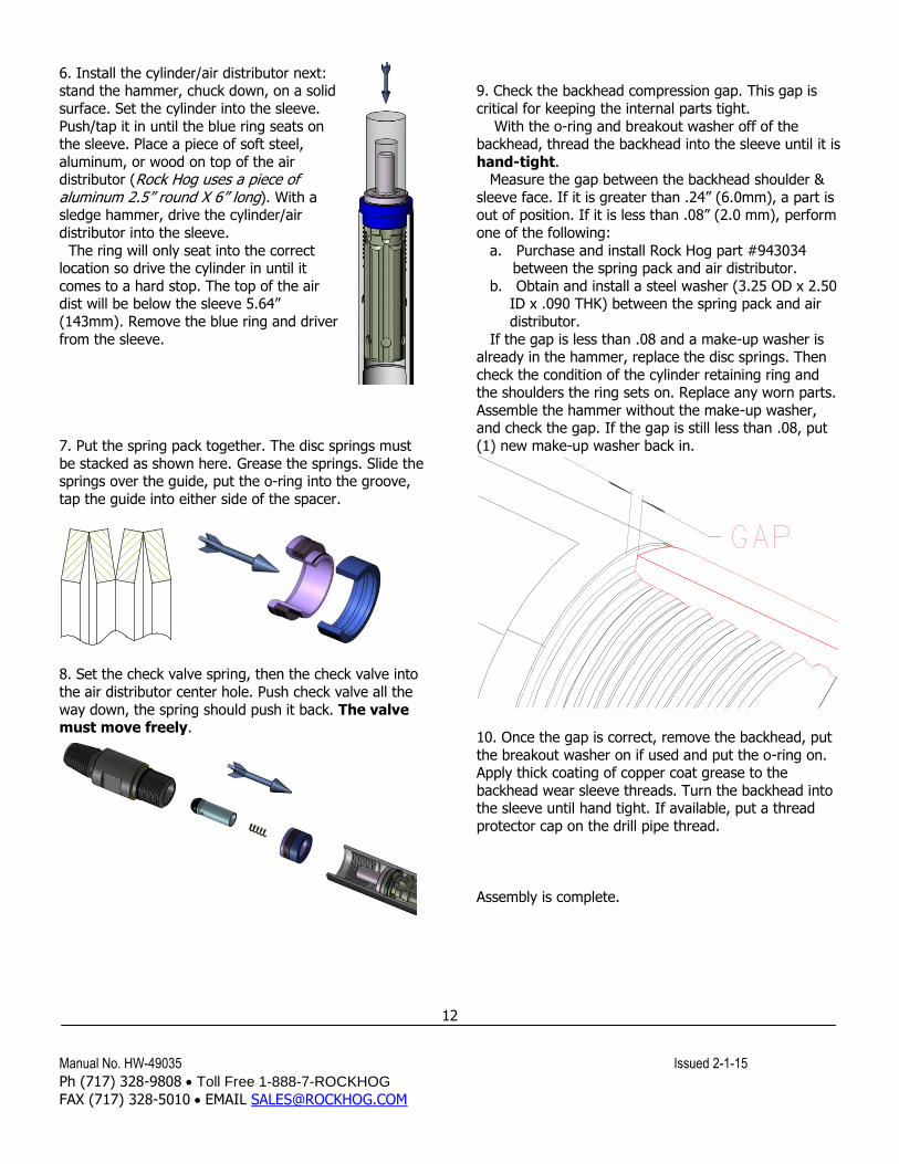
6. Install the cylinder/air distributor next: stand the hammer, chuck down, on a solid
surface. Set the cylinder into the sleeve.
Push/tap it in until the blue ring seats on the sleeve. Place a piece of soft steel,
aluminum, or wood on top of the air distributor (Rock Hog uses a piece of aluminum 2.5” round X 6” long). With a sledge hammer, drive the cylinder/air
distributor into the sleeve.
The ring will only seat into the correct location so drive the cylinder in until it
comes to a hard stop. The top of the air dist will be below the sleeve 5.64”
(143mm). Remove the blue ring and driver
from the sleeve.
7. Put the spring pack together. The disc springs must
be stacked as shown here. Grease the springs. Slide the springs over the guide, put the o-ring into the groove,
tap the guide into either side of the spacer.
8. Set the check valve spring, then the check valve into
the air distributor center hole. Push check valve all the
way down, the spring should push it back. The valve must move freely.
9. Check the backhead compression gap. This gap is
critical for keeping the internal parts tight.
With the o-ring and breakout washer off of the backhead, thread the backhead into the sleeve until it is
hand-tight. Measure the gap between the backhead shoulder &
sleeve face. If it is greater than .24” (6.0mm), a part is out of position. If it is less than .08” (2.0 mm), perform
one of the following:
a. Purchase and install Rock Hog part #943034 between the spring pack and air distributor.
b. Obtain and install a steel washer (3.25 OD x 2.50 ID x .090 THK) between the spring pack and air
distributor.
If the gap is less than .08 and a make-up washer is already in the hammer, replace the disc springs. Then
check the condition of the cylinder retaining ring and the shoulders the ring sets on. Replace any worn parts.
Assemble the hammer without the make-up washer, and check the gap. If the gap is still less than .08, put
(1) new make-up washer back in.
10. Once the gap is correct, remove the backhead, put
the breakout washer on if used and put the o-ring on. Apply thick coating of copper coat grease to the
backhead wear sleeve threads. Turn the backhead into the sleeve until hand tight. If available, put a thread
protector cap on the drill pipe thread.
Assembly is complete.

Manual No. HW-49035 Issued 2-1-15
Ph (717) 328-9808 Toll Free 1-888-7-ROCKHOG
FAX (717) 328-5010 EMAIL [email protected]
13
Section 4. Parts Breakdown
Exploded View, model RH40R9HP
Assembled View
Manual No. HW-49035 Issued 2-1-15
Ph (717) 328-9808 Toll Free 1-888-7-ROCKHOG
FAX (717) 328-5010 EMAIL [email protected]
14
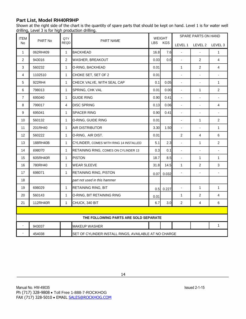
Part List, Model RH40R9HP Shown at the right side of the chart is the quantity of spare parts that should be kept on hand. Level 1 is for water well drilling, Level 3 is for high production drilling.
ITEM
NoPART No
QTY
REQDPART NAME
1 062RH409 1 BACKHEAD 16.8 7.6 - - 1
2 943016 2 WASHER, BREAKOUT 0.03 0.0 - 2 4
3 560232 1 O-RING, BACKHEAD 0.01 1 2 4
4 1102510 1 CHOKE SET, SET OF 2 0.01 - - -
5 922RH4 1 CHECK VALVE, WITH SEAL CAP 0.1 0.05 - - 1
6 798013 1 SPRING, CHK VAL 0.01 0.00 - 1 2
7 695040 1 GUIDE RING 0.90 0.41 - - -
8 799017 4 DISC SPRING 0.13 0.06 - - 4
9 695041 1 SPACER RING 0.90 0.41 - - -
10 560132 1 O-RING, GUIDE RING 0.01 - 1 2
11 201RH40 1 AIR DISTRIBUTOR 3.30 1.50 - - 1
12 560222 1 O-RING, AIR DIST. 0.01 2 4 6
13 188RH40B 1 CYLINDER, COMES WITH RING 14 INSTALLED 5.1 2.3 - 1 2
14 698070 1 RETAINING RING, COMES ON CYLINDER 13 0.3 0.1 - - -
15 605RH40R 1 PISTON 18.7 8.5 - 1 1
16 780RH40 1 WEAR SLEEVE 31.8 14.5 1 2 3
17 698071 1 RETAINING RING, PISTON 0.07 0.032 - - -
18 part not used in this hammer
19 698029 1 RETAINING RING, BIT 0.5 0.227 - 1 1
20 560143 1 O-RING, BIT RETAINING RING 0.01 1 2 4
21 112RH40R 1 CHUCK, 340 BIT 6.7 3.0 2 4 6
- 943037 MAKEUP WASHER 1
- 454038 SET OF CYLINDER INSTALL RINGS, AVAILABLE AT NO CHARGE
WEIGHT
LBS KGS
SPARE PARTS ON HAND
LEVEL 1 LEVEL 2 LEVEL 3
THE FOLLOWING PARTS ARE SOLD SEPARATE
Manual No. HW-49035 Issued 2-1-15
Ph (717) 328-9808 Toll Free 1-888-7-ROCKHOG
FAX (717) 328-5010 EMAIL [email protected]
15
Section 5. Trouble Shooting These are typical problems that can develop after the hammer has been in service:
Possible Causes
Piston will not cycle 1. Piston stuck in sleeve due to
a. Sleeve was pinched shut with wrench when threads were being loosened/tightened
b. Foreign material entered through drill string and jammed piston
c. Mud backed up into hammer (drilling under water), inspect the check valve 2. An internal part failed
Slow penetration, pressure ok
1. Dull or broken buttons on bit
2. Incorrect drill rotation or down pressure for the formation being drilled 3. Harder rock formation than the normal
Low pressure 1. Leak in the air line
2. Leak in the hammer (cracked or broken part) 3. Compressor output problem
High pressure
1. Air line is partially closed off 2. Foreign material clogging air passages in hammer
3. Bit blow holes are clogged