Embed Size (px)
Citation preview

Mitsubishi Industrial RobotCR750-Q/CR751-Q Controller
RH-3FH-Q SeriesStandard Specifications Manual
BFP-A8880-AD

All teaching work must be carried out by an operator who has received special training. (This also applies to maintenance work with the power source turned ON.)Enforcement of safety training
For teaching work, prepare a work plan related to the methods and procedures of operating the robot, and to the measures to be taken when an error occurs or when restarting. Carry out work following this plan. (This also applies to maintenance work with the power source turned ON.)Preparation of work plan
Prepare a device that allows operation to be stopped immediately during teaching work. (This also applies to maintenance work with the power source turned ON.)Setting of emergency stop switch
During teaching work, place a sign indicating that teaching work is in progress on the start switch, etc. (This also applies to maintenance work with the power source turned ON.)Indication of teaching work in progress
Provide a fence or enclosure during operation to prevent contact of the operator and robot.Installation of safety fence
Establish a set signaling method to the related operators for starting work, and follow this method.Signaling of operation start
As a principle turn the power OFF during maintenance work. Place a sign indicating that maintenance work is in progress on the start switch, etc.Indication of maintenance work in progress
Before starting work, inspect the robot, emergency stop switch and other related devices, etc., and confirm that there are no errors.Inspection before starting work
Always read the following precautions and the separate "Safety Manual" before starting use of the robot to learn the required measures to be taken.
Safety Precautions
CAUTION
CAUTION
WARNING
CAUTION
DANGER
CAUTION
CAUTION
CAUTION
The points of the precautions given in the separate "Safety Manual" are given below.Refer to the actual "Safety Manual" for details.
When automatic operation of the robot is performed using multiple control devices (GOT, programmable controller, push-button switch), the interlocking of operation rights of the devices, etc. must be designed by the customer.
Use the robot within the environment given in the specifications. Failure to do so could lead to a drop or reliability or faults. (Temperature, humidity, atmosphere, noise environment, etc.)
Transport the robot with the designated transportation posture. Transporting the robot in a non-designated posture could lead to personal injuries or faults from dropping.
Always use the robot installed on a secure table. Use in an instable posture could lead to positional deviation and vibration.
Wire the cable as far away from noise sources as possible. If placed near a noise source, positional deviation or malfunction could occur.
Do not apply excessive force on the connector or excessively bend the cable. Failure to observe this could lead to contact defects or wire breakage.
Make sure that the workpiece weight, including the hand, does not exceed the rated load or tolerable torque. Exceeding these values could lead to alarms or faults.
Securely install the hand and tool, and securely grasp the workpiece. Failure to observe this could lead to personal injuries or damage if the object comes off or flies off during operation.
Securely ground the robot and controller. Failure to observe this could lead to malfunctioning by noise or to electric shock accidents.
Indicate the operation state during robot operation. Failure to indicate the state could lead to operators approaching the robot or to incorrect operation.
When carrying out teaching work in the robot's movement range, always secure the priority right for the robot control. Failure to observe this could lead to personal injuries or damage if the robot is started with external commands.
Keep the jog speed as low as possible, and always watch the robot. Failure to do so could lead to interference with the workpiece or peripheral devices.
After editing the program, always confirm the operation with step operation before starting automatic operation. Failure to do so could lead to interference with peripheral devices because of programming mistakes, etc.
Make sure that if the safety fence entrance door is opened during automatic operation, the door is locked or that the robot will automatically stop. Failure to do so could lead to personal injuries.
Never carry out modifications based on personal judgments, or use non-designated maintenance parts. Failure to observe this could lead to faults or failures.
DANGER
CAUTION
CAUTION
CAUTION
CAUTION
CAUTION
CAUTION
WARNING
WARNING
CAUTION
WARNING
CAUTION
CAUTION
CAUTION
CAUTION
When the robot arm has to be moved by hand from an external area, do not place hands or fingers in the openings. Failure to observe this could lead to hands or fingers catching depending on the posture.
Do not stop the robot or apply emergency stop by turning the robot controller's main power OFF. If the robot controller main power is turned OFF during automatic operation, the robot accuracy could be adversely affected. Moreover, it may interfere with the peripheral device by drop or move by inertia of the arm.
Do not turn off the main power to the robot controller while rewriting the internal information of the robot controller such as the program or parameters.
If the main power to the robot controller is turned off while in automatic operation or rewriting the program or parameters, the internal information of the robot controller may be damaged.
Do not connect the Handy GOT when using the GOT direct connection function of this product. Failure to observe this may result in property damage or bodily injury because the Handy GOT can automatically operate the robot regardless of whether the operation rights are enabled or not.
Do not connect the Handy GOT to a programmable controller when using an iQ Platform compatible product with the CR7xx-Q controller. Failure to observe this may result in property damage or bodily injury because the Handy GOT can automatically operate the robot regardless of whether the operation rights are enabled or not.
Do not remove the SSCNET III cable while power is supplied to the multiple CPU system or the servo amplifier. Do not look directly at light emitted from the tip of SSCNET III connectors or SSCNET III cables of the Motion CPU or the servo amplifier. Eye discomfort may be felt if exposed to the light. (Reference: SSCNET III employs a Class 1 or equivalent light source as specified in JIS C 6802 and IEC60825-1 (domestic standards in Japan).)
Do not remove the SSCNET III cable while power is supplied to the controller. Do not look directly at light emitted from the tip of SSCNET III connectors or SSCNET III cables. Eye discomfort may be felt if exposed to the light. (Reference: SSCNET III employs a Class 1 or equivalent light source as specified in JIS C 6802 and IEC60825-1 (domestic standards in Japan).)
Attach the cap to the SSCNET III connector after disconnecting the SSCNET III cable. If the cap is not attached, dirt or dust may adhere to the connector pins, resulting in deterioration connector properties, and leading to malfunction.
Make sure there are no mistakes in the wiring. Connecting differently to the way
specified in the manual can result in errors, such as the emergency stop not being released. In order to prevent errors occurring, please be sure to check that all functions (such as the teaching box emergency stop, customer emer-gency stop, and door switch) are working properly after the wiring setup is com-pleted.
WARNING
CAUTION
CAUTION
DANGER
DANGER
DANGER
DANGER
DANGER
CAUTION

Use the network equipments (personal computer, USB hub, LAN hub, etc) confirmed by manufacturer. The thing unsuitable for the FA environment (related with conformity, temperature or noise) exists in the equipments connected to USB. When using network equipment, measures against the noise, such as measures against EMI and the addition of the ferrite core, may be necessary. Please fully confirm the operation by customer. Guarantee and maintenance of the equipment on the market (usual office automation equipment) cannot be performed.
To maintain the safety of the robot system against unauthorized access from external devices via the network, take appropriate measures.
To maintain the safety against unauthorized access via the Internet, take mea-sures such as installing a firewall.
CAUTION
CAUTION
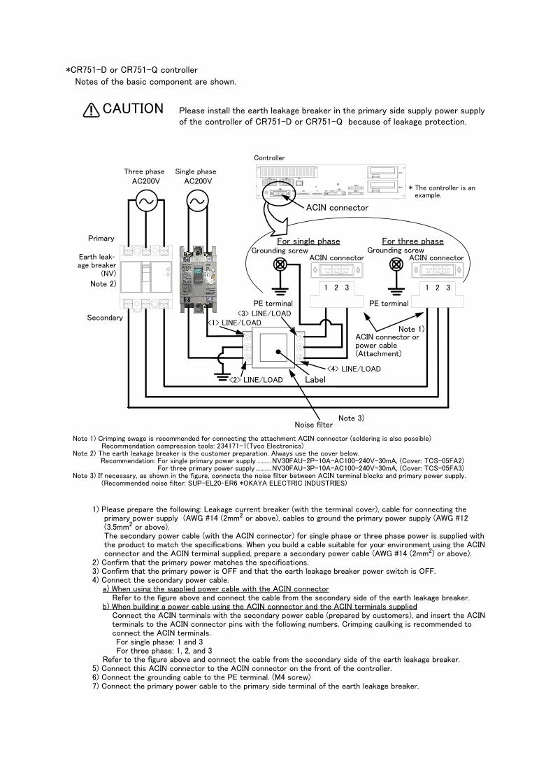
*CR751-D or CR751-Q controller
Notes of the basic component are shown.
Please install the earth leakage breaker in the primary side supply power supply of the controller of CR751-D or CR751-Q because of leakage protection.
1) Please prepare the following: Leakage current breaker (with the terminal cover), cable for connecting the primary power supply (AWG #14 (2mm2 or above), cables to ground the primary power supply (AWG #12 (3.5mm2 or above).The secondary power cable (with the ACIN connector) for single phase or three phase power is supplied with the product to match the specifications. When you build a cable suitable for your environment using the ACIN connector and the ACIN terminal supplied, prepare a secondary power cable (AWG #14 (2mm2) or above).
2) Confirm that the primary power matches the specifications.3) Confirm that the primary power is OFF and that the earth leakage breaker power switch is OFF.4) Connect the secondary power cable.
a) When using the supplied power cable with the ACIN connectorRefer to the figure above and connect the cable from the secondary side of the earth leakage breaker.
b) When building a power cable using the ACIN connector and the ACIN terminals suppliedConnect the ACIN terminals with the secondary power cable (prepared by customers), and insert the ACIN terminals to the ACIN connector pins with the following numbers. Crimping caulking is recommended to connect the ACIN terminals.For single phase: 1 and 3For three phase: 1, 2, and 3
Refer to the figure above and connect the cable from the secondary side of the earth leakage breaker.5) Connect this ACIN connector to the ACIN connector on the front of the controller.6) Connect the grounding cable to the PE terminal. (M4 screw) 7) Connect the primary power cable to the primary side terminal of the earth leakage breaker.
CAUTION
PE terminal
Grounding screw
Controller
ACIN connector
AC200V AC200V
Primary
Secondary
PE terminal
Grounding screw
1 2 3 1 2 3
ACIN connector
ACIN connector
Note 2)
Note 1) Crimping swage is recommended for connecting the attachment ACIN connector (soldering is also possible)Recommendation compression tools: 234171-1(Tyco Electronics)
Note 2) The earth leakage breaker is the customer preparation. Always use the cover below.Recommendation: For single primary power supply ......... NV30FAU-2P-10A-AC100-240V-30mA, (Cover: TCS-05FA2)
For three primary power supply .......... NV30FAU-3P-10A-AC100-240V-30mA, (Cover: TCS-05FA3)Note 3) If necessary, as shown in the figure, connects the noise filter between ACIN terminal blocks and primary power supply.
(Recommended noise filter: SUP-EL20-ER6 *OKAYA ELECTRIC INDUSTRIES)
Controller
<4> LINE/LOAD
<3> LINE/LOAD<1> LINE/LOAD
<2> LINE/LOAD
Noise filter
Label
ACIN connector or power cable (Attachment)
Note 1)
For three phaseFor single phase
Three phase Single phase
Earth leak-age breaker
(NV)
Note 3)
* The controller is an example.
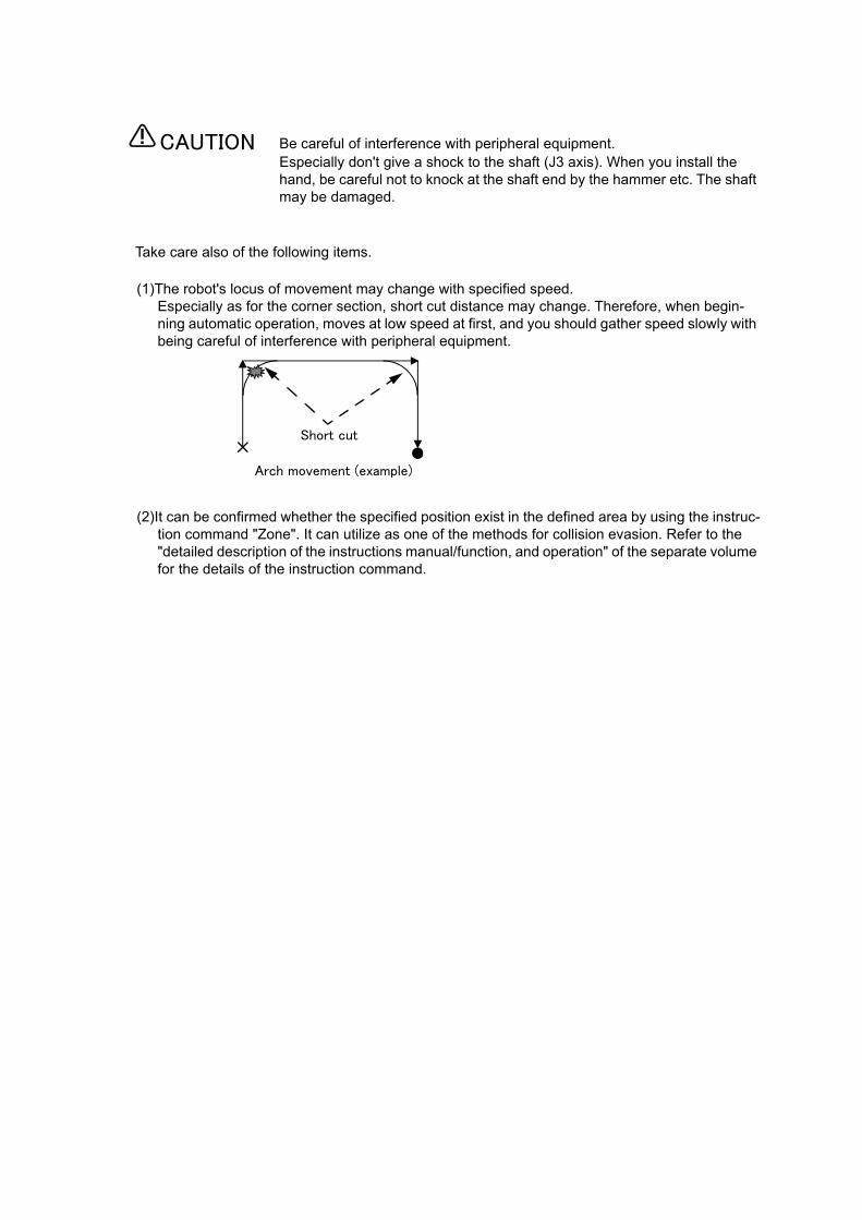
Be careful of interference with peripheral equipment.Especially don't give a shock to the shaft (J3 axis). When you install the hand, be careful not to knock at the shaft end by the hammer etc. The shaft may be damaged.
Take care also of the following items.
(1)The robot's locus of movement may change with specified speed. Especially as for the corner section, short cut distance may change. Therefore, when begin-ning automatic operation, moves at low speed at first, and you should gather speed slowly with being careful of interference with peripheral equipment.
(2)It can be confirmed whether the specified position exist in the defined area by using the instruc-tion command "Zone". It can utilize as one of the methods for collision evasion. Refer to the "detailed description of the instructions manual/function, and operation" of the separate volume for the details of the instruction command.
CAUTION
Short cut
Arch movement (example)
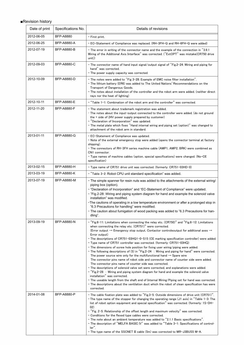
■Revision history
Date of print Specifications No. Details of revisions
2012-06-05 BFP-A8880 ・ First print.
2012-06-25 BFP-A8880-A ・ EC-Statement of Compliance was replaced. (RH-3FH-Q and RH-6FH-Q were added)
2012-07-19 BFP-A8880-B ・ The error in writing of the connector name and the example of the connection in "3.9.1
Wiring of the Additional Axis Interface" was corrected. ("ExtOPT" was mistake(CR750 drive
unit))
2012-09-03 BFP-A8880-C ・ The connector name of hand input signal/output signal of "Fig.2-24: Wiring and piping for
hand" was corrected.
・ The power supply capacity was corrected.
2012-10-09 BFP-A8880-D ・ The notes were added to "Fig 3-28: Example of EMC noise filter installation".
・ The lithium battery (ER6) was added to The United Nations’Recommendations on the
Transport of Dangerous Goods.
・ The notes about installation of the controller and the robot arm were added. (neither direct
rays nor the heat of lighting)
2012-10-11 BFP-A8880-E ・ “Table 1-1: Combination of the robot arm and the controller” was corrected.
2012-11-20 BFP-A8880-F ・ The statement about trademark registration was added.
・ The notes about the input-output connected to the controller were added. (do not ground
the + side of 24V power supply prepared by customer)
・ ”Declaration of Incorporation” was updated.
・ The metal plate which fixes "Hand internal wiring and piping set (option)" was changed to
attachment of the robot arm in standard.
2013-01-11 BFP-A8880-G ・ EC-Statement of Compliance was updated.
・ Note of the external emergency stop were added (opens the connector terminal at factory
shipping).
・ The connectors of RH-3FH series machine cable (AMP1, AMP2, BRK) were combined as
CN1 connector.
・ Type names of machine cables (option, special specifications) were changed. (No-CE
specification)
2013-02-15 BFP-A8880-H ・ Type name of CR751 drive unit was corrected. (formerly: CR751-03HD-0)
2013-03-19 BFP-A8880-K ・ ”Table 3-2: Robot CPU unit standard specification” was added.
2013-07-19 BFP-A8880-M ・ The simple spanner for resin nuts was added to the attachments of the external wiring/piping box (option).
・ ”Declaration of Incorporation” and “EC-Statement of Compliance” were updated.・ ”Fig.2-28: Wiring and piping system diagram for hand and example the solenoid valve
installation” was modified.・The cautions of operating in a low temperature environment or after a prolonged stop in
”6.3 Precautions for handling” were modified.・ The caution about fumigation of wood packing was added to ”6.3 Precautions for han-
dling”.
2013-09-19 BFP-A8880-N ・ ”Fig.6-11: Limitations when connecting the relay etc. (CR750)” and ”Fig.6-12: Limitations
when connecting the relay etc. (CR751)” were corrected.
(Error output → Emergency stop output, Contactor controleoutput for additional axes →
Error output)
・ The descriptions of CR751-03HQ1-0-S15 (CE marking specification controller) were added.
・ Type name of CR751 controller was corrected. (formerly: CR751-03HQ)
・ The dimensions of screw hole position for fixing user wiring/piping were added.
・ The following descriptions of (5) in ”Fig.2-24 : Wiring and piping for hand” were corrected.
The power source wire only for the multifunctional hand → Spare wire
The connector pins name of robot side and connector name of counter side were added.
The connector pins name of counter side was corrected.
・ The descriptions of solenoid valve set were corrected, and explanations were added.
・ ”Fig.2-28 : Wiring and piping system diagram for hand and example the solenoid valve
installation” was corrected.
・ The useable length from the shaft end of Internal Wiring/Piping set for hand was corrected.
・ The descriptions about the ventilation duct which the robot of clean specification has were
corrected.
2014-01-08 BFP-A8880-P ・ The cable fixation plate was added to ”Fig.3-5: Outside dimensions of drive unit (CR751)”.
・The type name of the stopper for changing the operating range (J1 axis) in “Table 1-3: The
list of robot option equipment and special specification” was corrected. (formerly: 1S-DH-
02)
・ ”Fig. 2-5: Relationship of the offset length and maximum velocity” was corrected.
・ Conditions for the flexed type cables were corrected.
・ The note about an ambient temperature was added to “2.1.1 Basic specifications”.
・ The description of "MELFA BASIC IV" was added to “Table 3-1: Specifications of control-ler”.
・ The type name of the SSCNET III cable (5m) was corrected to MR-J3BUS5 M-A.
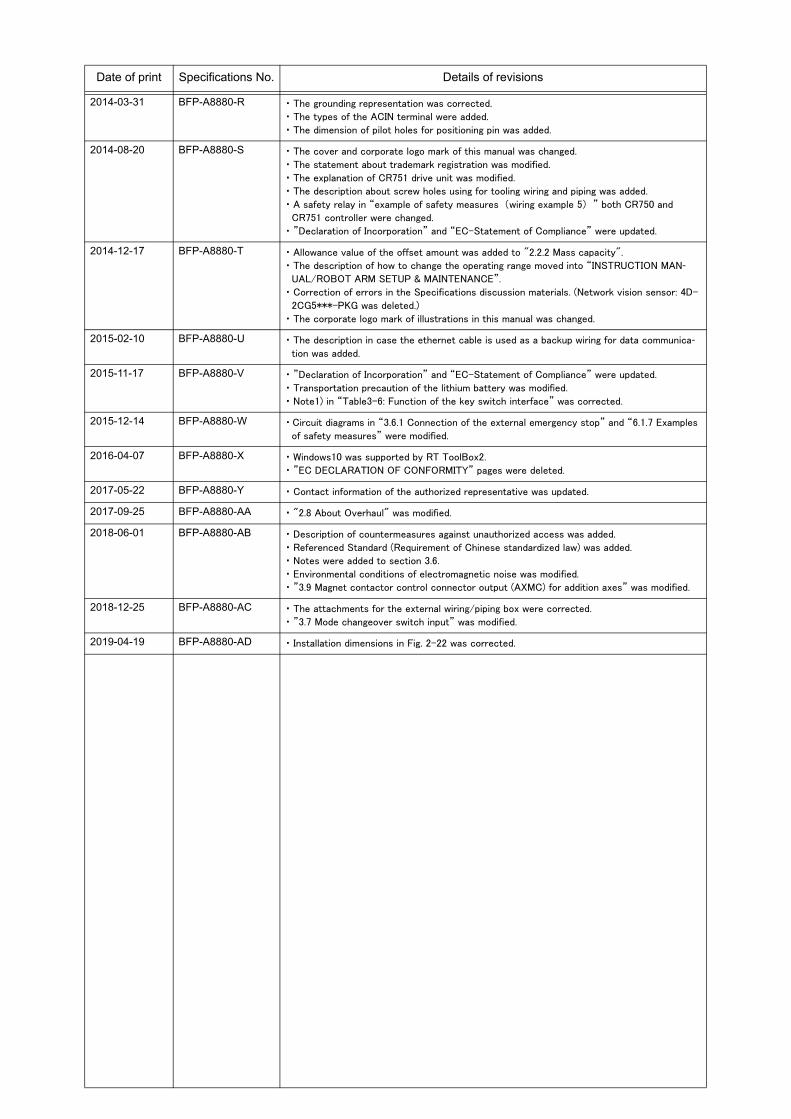
2014-03-31 BFP-A8880-R ・ The grounding representation was corrected.
・ The types of the ACIN terminal were added.
・ The dimension of pilot holes for positioning pin was added.
2014-08-20 BFP-A8880-S ・ The cover and corporate logo mark of this manual was changed.
・ The statement about trademark registration was modified.
・ The explanation of CR751 drive unit was modified.
・ The description about screw holes using for tooling wiring and piping was added.
・ A safety relay in “example of safety measures (wiring example 5) ” both CR750 and
CR751 controller were changed.
・ ”Declaration of Incorporation” and “EC-Statement of Compliance” were updated.
2014-12-17 BFP-A8880-T ・ Allowance value of the offset amount was added to "2.2.2 Mass capacity".
・ The description of how to change the operating range moved into “INSTRUCTION MAN-UAL/ROBOT ARM SETUP & MAINTENANCE”.
・ Correction of errors in the Specifications discussion materials. (Network vision sensor: 4D-
2CG5***-PKG was deleted.)
・ The corporate logo mark of illustrations in this manual was changed.
2015-02-10 BFP-A8880-U ・ The description in case the ethernet cable is used as a backup wiring for data communica-tion was added.
2015-11-17 BFP-A8880-V ・ ”Declaration of Incorporation” and “EC-Statement of Compliance” were updated.
・ Transportation precaution of the lithium battery was modified.
・ Note1) in “Table3-6: Function of the key switch interface” was corrected.
2015-12-14 BFP-A8880-W ・ Circuit diagrams in “3.6.1 Connection of the external emergency stop” and “6.1.7 Examples
of safety measures” were modified.
2016-04-07 BFP-A8880-X ・ Windows10 was supported by RT ToolBox2.
・ ”EC DECLARATION OF CONFORMITY” pages were deleted.
2017-05-22 BFP-A8880-Y ・ Contact information of the authorized representative was updated.
2017-09-25 BFP-A8880-AA ・ "2.8 About Overhaul" was modified.
2018-06-01 BFP-A8880-AB ・ Description of countermeasures against unauthorized access was added.
・ Referenced Standard (Requirement of Chinese standardized law) was added.
・ Notes were added to section 3.6.
・ Environmental conditions of electromagnetic noise was modified.
・ ”3.9 Magnet contactor control connector output (AXMC) for addition axes” was modified.
2018-12-25 BFP-A8880-AC ・ The attachments for the external wiring/piping box were corrected.
・ ”3.7 Mode changeover switch input” was modified.
2019-04-19 BFP-A8880-AD ・ Installation dimensions in Fig. 2-22 was corrected.
Date of print Specifications No. Details of revisions

■ Introduction
This series offers small-size industrial robots developed using Mitsubishi's latest technology. They are especially designed to handle and assemble mechanical parts. They are Mitsubishi's answer to the cus-tomer's need to achieve a compact manufacturing facility capable of highly flexible production, as neces-sitated by the diffusion of high-density product groups and the shorter product life cycles that have become common-place in recent years.
However, to comply with the target application, a work system having a well-balanced robot arm, periph-eral devices or robot and hand section must be structured.
When creating these standard specifications, we have edited them so that the Mitsubishi robot's charac-teristics and specifications can be easily understood by users considering the implementation of robots. However, if there are any unclear points, please contact your nearest Mitsubishi branch or dealer.
Mitsubishi hopes that you will consider these standard specifications and use our robots.
Note that in this specification document the specifications related to the robot arm is described Page 8, "2 Robot arm", the specifications related to the controller Page 62, "3 Controller", and software func-tions and a command list Page 112, "4 Software" separately.
This document has indicated the specification of the following types robot.
*RH-3FH-Q series
・ About CE Marking in the automization system The Guidelines of the measures against EMC in the automization system manufactured by the cus-tomer is shown in Page 136, "6.4 EMC installation guideline". Please refer to it and carry out the measures against EMC of the automization system of the cus-tomer.
・ No part of this manual may be reproduced by any means or in any form, without prior consent from Mit-subishi.
・ The contents of this manual are subject to change without notice.・ The specifications values are based on Mitsubishi standard testing methods.・ The information contained in this document has been written to be accurate as much as possible.
Please interpret that items not described in this document "cannot be performed." or "alarmmay occur". Please contact your nearest dealer if you find any doubtful, wrong or skipped point.
・ This specifications is original.・ Microsoft, Windows, Windows XP, Windows Vista, Windows 7, Windows 8, Windows 8.1, Windows 10 are
either registered trademarks or trademarks of Microsoft Corporation in the United States and/or othercountries.
・ The official name of Windows® is Microsoft®Windows®Operating System.・ Windows®XP, Windows Vista®, Windows® 7, Windows® 8, Windows® 8.1, Windows® 10 are either prod-
uct names of Microsoft Corporation in the United States.・ Ethernet is registered trademarks or trademarks of Xerox Corporation in the United States.・ All other company names and production names in this document are the trademarks or registered
trademarks of their respective owners.・ Referenced Standard (Requirement of Chinese standardized law): This Product is designed and manu-
factured accordance with GB 11291.1.
Copyright(C) 2012-2019 MITSUBISHI ELECTRIC CORPORATION
Contents
i
Page
1 General configuration .................................................................................................................................................................... 1-1
1.1 Structural equipment ............................................................................................................................................................. 1-11.1.1 Standard structural equipment .................................................................................................................................. 1-11.1.2 Special specifications .................................................................................................................................................... 1-11.1.3 Options ................................................................................................................................................................................. 1-11.1.4 Maintenance parts ........................................................................................................................................................... 1-1
1.2 Model type name of robot .................................................................................................................................................... 1-21.2.1 How to identify the robot model ................................................................................................................................ 1-21.2.2 Combination of the robot arm and the controller .............................................................................................. 1-3
1.3 CE marking specifications .................................................................................................................................................... 1-3
1.4 Indirect export .......................................................................................................................................................................... 1-3
1.5 Instruction manuals ................................................................................................................................................................ 1-3
1.6 Contents of the structural equipment ............................................................................................................................ 1-41.6.1 Robot arm ........................................................................................................................................................................... 1-41.6.2 Controller ............................................................................................................................................................................ 1-5
1.7 Contents of the Option equipment and special specification .............................................................................. 1-6
2 Robot arm ........................................................................................................................................................................................... 2-8
2.1 Standard specifications ........................................................................................................................................................ 2-82.1.1 Basic specifications ........................................................................................................................................................ 2-8
(1) Standard specification ............................................................................................................................................... 2-8(2) Clean specification ................................................................................................................................................... 2-10
2.1.2 The counter-force applied to the installation surface ................................................................................... 2-11
2.2 Definition of specifications ................................................................................................................................................ 2-122.2.1 Pose repeatability .......................................................................................................................................................... 2-122.2.2 Mass capacity .................................................................................................................................................................. 2-132.2.3 Relationships Among Mass Capacity, Speed, and Acceleration/Deceleration Speed ...................... 2-14
(1) Setting Load Capacity and Size (Hand Conditions) .................................................................................... 2-142.2.4 Vibrations at the Tip of the Arm during Low-Speed Operation of the Robot ..................................... 2-142.2.5 Vibration of shaft (J3 axis) position and arm end ............................................................................................ 2-15
(1) Relationship Between Mass Capacity and Speed ....................................................................................... 2-15(2) Relationship Between Height of Shaft (J3 Axis) and Acceleration/Deceleration Speed ........... 2-16(3) Relation between offset length and the maximum speed ......................................................................... 2-17(4) Time to reach the position repeatability ......................................................................................................... 2-18
2.2.6 Collision detection ......................................................................................................................................................... 2-182.2.7 Protection specifications ............................................................................................................................................ 2-19
(1) Types of protection specifications .................................................................................................................... 2-192.2.8 Clean specifications ...................................................................................................................................................... 2-19
(1) Types of clean specifications ............................................................................................................................... 2-19
2.3 Names of each part of the robot .................................................................................................................................... 2-21
2.4 Outside dimensions ・ Operating range diagram ........................................................................................................ 2-222.4.1 Outside dimensions ・ Operating range diagram ................................................................................................ 2-22
(1) Standard Specification ............................................................................................................................................ 2-22(2) Clean Specification ................................................................................................................................................... 2-28
2.4.2 Mechanical interface and Installation surface ................................................................................................... 2-342.4.3 Outside dimensions of machine cables ................................................................................................................ 2-35
(1) Connection with the CR750 controller ............................................................................................................ 2-35(2) Connection with the CR751 controller ............................................................................................................ 2-35
2.5 Tooling ........................................................................................................................................................................................ 2-362.5.1 Wiring and piping for hand .......................................................................................................................................... 2-362.5.2 Internal air piping ............................................................................................................................................................ 2-37
(1) Standard type ............................................................................................................................................................. 2-37(2) Clean type .................................................................................................................................................................... 2-37
2.5.3 Internal wiring for the hand output cable ............................................................................................................ 2-372.5.4 Internal wiring for the hand input cable ................................................................................................................ 2-372.5.5 Ethernet cable ............................................................................................................................................................... 2-37
Contents
ii
Page
2.5.6 About the Installation of Tooling Wiring and Piping (Examples of Wiring and Piping) ....................... 2-38(1) Example of wiring and piping <1> ........................................................................................................................ 2-39(2) Wiring and piping example <2> ............................................................................................................................. 2-39(3) Precautions for the clean specification ........................................................................................................... 2-40
2.5.7 Wiring and piping system diagram for hand ......................................................................................................... 2-412.5.8 Electrical specifications of hand input/output .................................................................................................. 2-422.5.9 Air supply circuit example for the hand ............................................................................................................... 2-43
2.6 Shipping special specifications, options, and maintenance parts ...................................................................... 2-442.6.1 Shipping special specifications ................................................................................................................................. 2-44
(1) Machine cable ............................................................................................................................................................. 2-45
2.7 Options ....................................................................................................................................................................................... 2-46(1) Machine cable extension ........................................................................................................................................ 2-47(2) Changes J1 axis operating range ....................................................................................................................... 2-51(3) Solenoid valve set ..................................................................................................................................................... 2-52(4) Hand input cable ........................................................................................................................................................ 2-54(5) Hand output cable ..................................................................................................................................................... 2-55(6) Hand curl tube ............................................................................................................................................................ 2-56(7) Internal Wiring/Piping set for hand .................................................................................................................... 2-57(8) External Wiring/Piping box .................................................................................................................................... 2-58
2.8 About Overhaul ...................................................................................................................................................................... 2-60
2.9 Maintenance parts ................................................................................................................................................................. 2-61
3 Controller .......................................................................................................................................................................................... 3-62
3.1 Standard specifications ...................................................................................................................................................... 3-623.1.1 Basic specifications ...................................................................................................................................................... 3-623.1.2 Protection specifications and operating supply ................................................................................................ 3-63
3.2 Names of each part .............................................................................................................................................................. 3-643.2.1 Drive unit ........................................................................................................................................................................... 3-64
(1) CR750 drive unit ........................................................................................................................................................ 3-64(2) CR751 drive unit ........................................................................................................................................................ 3-66
3.2.2 Robot CPU ........................................................................................................................................................................ 3-68
3.3 Outside dimensions/Installation dimensions .............................................................................................................. 3-693.3.1 Outside dimensions ....................................................................................................................................................... 3-69
(1) CR750 drive unit ........................................................................................................................................................ 3-69(2) CR751 drive unit ........................................................................................................................................................ 3-70(3) Outside dimensions of robot CPU unit ............................................................................................................ 3-71(4) Battery unit outside dimension ........................................................................................................................... 3-72
3.3.2 Installation dimensions ................................................................................................................................................. 3-73(1) CR750 drive unit ........................................................................................................................................................ 3-73(2) CR751 drive unit ........................................................................................................................................................ 3-75(3) Robot CPU Unit installation dimensions .......................................................................................................... 3-77
3.4 External input/output .......................................................................................................................................................... 3-783.4.1 Types .................................................................................................................................................................................. 3-78
3.5 Dedicated input/output ...................................................................................................................................................... 3-79
3.6 Emergency stop input and output etc. ......................................................................................................................... 3-823.6.1 Connection of the external emergency stop ...................................................................................................... 3-82
(1) CR750 drive unit ........................................................................................................................................................ 3-83(2) CR751 drive unit ........................................................................................................................................................ 3-87
3.6.2 Special stop input (SKIP) ........................................................................................................................................... 3-90(1) CR750 drive unit ........................................................................................................................................................ 3-90(2) CR751 drive unit ........................................................................................................................................................ 3-91
3.6.3 Door switch function .................................................................................................................................................... 3-923.6.4 Enabling device function ............................................................................................................................................. 3-92
(1) When door is opening ............................................................................................................................................... 3-92(2) When door is closing ................................................................................................................................................ 3-93(3) Automatic Operation/Jog Operation/Brake Release and Necessary Switch Settings .............. 3-93
Contents
iii
Page
3.7 Mode changeover switch input ........................................................................................................................................ 3-94(1) Specification of the key switch interface ....................................................................................................... 3-94(2) Connection of the mode changeover switch input ..................................................................................... 3-96
3.8 Additional Axis Function ..................................................................................................................................................... 3-973.8.1 Wiring of the Additional Axis Interface ................................................................................................................. 3-97
(1) CR750 drive unit ........................................................................................................................................................ 3-97(2) CR751 drive unit ........................................................................................................................................................ 3-98
3.9 Magnet contactor control connector output (AXMC) for addition axes ..................................................... 3-101(1) Example circuit ........................................................................................................................................................ 3-101(2) Image of how to connect the controller connector ................................................................................. 3-103
3.10 Options ................................................................................................................................................................................. 3-104(1) Teaching pendant (T/B) ...................................................................................................................................... 3-105(2) MELSOFT RT ToolBox2/RT ToolBox2 mini ............................................................................................... 3-108(3) Instruction Manual (bookbinding) ..................................................................................................................... 3-110
3.11 Maintenance parts ........................................................................................................................................................... 3-111
4 Software ......................................................................................................................................................................................... 4-112
4.1 List of commands ............................................................................................................................................................... 4-112
4.2 List of parameters .............................................................................................................................................................. 4-115
5 Instruction Manual ..................................................................................................................................................................... 5-117
5.1 The details of each instruction manuals ................................................................................................................... 5-117
6 Safety .............................................................................................................................................................................................. 6-118
6.1 Safety ...................................................................................................................................................................................... 6-1186.1.1 Self-diagnosis stop functions ................................................................................................................................ 6-1186.1.2 External input/output signals that can be used for safety protection measures ........................... 6-1196.1.3 Precautions for using robot .................................................................................................................................... 6-1196.1.4 Safety measures for automatic operation ........................................................................................................ 6-1206.1.5 Safety measures for teaching ............................................................................................................................... 6-1206.1.6 Safety measures for maintenance and inspections, etc. ........................................................................... 6-1206.1.7 Examples of safety measures ................................................................................................................................ 6-121
(1) CR750 drive unit ..................................................................................................................................................... 6-121(2) CR751 drive unit ..................................................................................................................................................... 6-126(3) External emergency stop connection [supplementary explanation] ................................................. 6-131
6.2 Working environment ......................................................................................................................................................... 6-134
6.3 Precautions for handling .................................................................................................................................................. 6-134
6.4 EMC installation guideline ............................................................................................................................................... 6-1366.4.1 Outlines ........................................................................................................................................................................... 6-1366.4.2 EMC directive ............................................................................................................................................................... 6-1366.4.3 EMC measures ............................................................................................................................................................. 6-1376.4.4 Component parts for EMC measures ................................................................................................................. 6-137
(1) Ferrite core ............................................................................................................................................................... 6-137(2) Line noise filter ....................................................................................................................................................... 6-137
7Appendix ........................................................................................................................................................................... Appendix-138Appendix 1 : Specifications discussion material ........................................................................................ Appendix-138
1General configuration
Structural equipment 1-1
1 General configuration
1.1 Structural equipment
Structural equipment consists of the following types.
1.1.1 Standard structural equipmentThe following items are enclosed as a standard.
(1) Robot arm (2) Controller (CPU unit + Drive unit)(3) The connecting cable for the CPU unit and the drive unit(4) Machine cable(5) Robot arm installation bolts(6) Safety manual, CD-ROM (Instruction manual)(7) Guarantee card
1.1.2 Special specificationsFor the special specifications, some standard configuration equipment and specifications have to be changed before factory shipping. Confirm the delivery date and specify the special specifications at the order.
1.1.3 OptionsUser can install options after their delivery.
1.1.4 Maintenance partsMaterials and parts for the maintenance use.

1-2 Model type name of robot
1General configuration
1.2 Model type name of robotThis robot has arranged the type name corresponding to load mass, arm length, and environment specification. Details are shown below, please select the robot suitable for the customer's use.
1.2.1 How to identify the robot model
RH - 3 FH □□ △△ ○ - 1 Q ▲ - Sxx(a) (b) (c) (d) (e) (f) (g) (h) ( i ) ( j )
(a). RH ............................................. Indicates the horizontal multiple-joint robot.
(b). 3................................................. Indicates the maximum load.3: 3kg
(c). FH............................................. Indicates the FH series.
(d). □□.......................................... Indicates the arm length.Ex.)
35: 350mm45: 450mm55: 550mm
(e). △△.......................................... Indicates the vertical stroke length.Ex.)
12: 120mm stroke15: 150mm stroke
(f). ○................................................ Indicates environment specification.Ex.)
Omitted: General specificationsC: Clean specifications
(g). 1 ................................................. Indicates the controller series.Ex.)
Omitted: CR750 controller1: CR751 controller
(h). Q ................................................ Indicates the controller type.Q: iQ Platform
(i). ▲ ................................................ Technical standard of Conformity.Ex.)
Omitted: No conformity of technical standard.1: Conforms to the CE Marking
(j). - S xx.................................... Indicates a special model. In order, limit special specification.
1General configuration
CE marking specifications 1-3
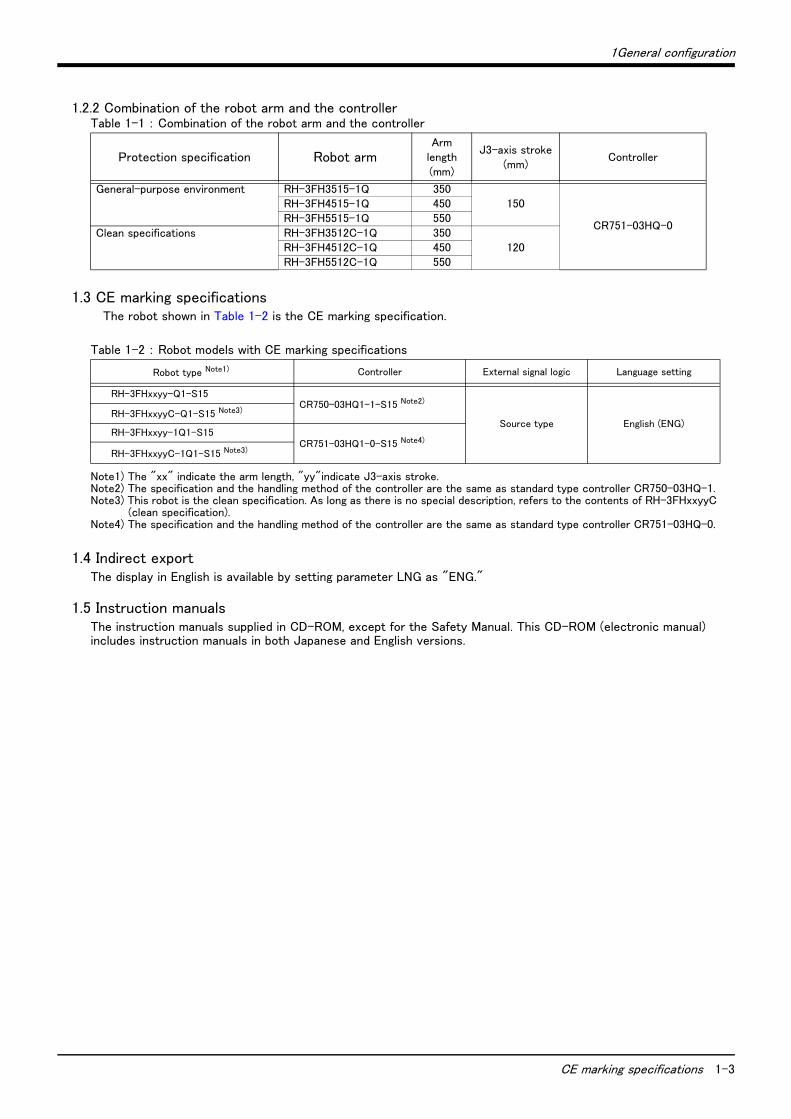
1.2.2 Combination of the robot arm and the controllerTable 1-1 : Combination of the robot arm and the controller
1.3 CE marking specificationsThe robot shown in Table 1-2 is the CE marking specification.
Table 1-2 : Robot models with CE marking specifications
1.4 Indirect exportThe display in English is available by setting parameter LNG as "ENG."
1.5 Instruction manualsThe instruction manuals supplied in CD-ROM, except for the Safety Manual. This CD-ROM (electronic manual) includes instruction manuals in both Japanese and English versions.
Protection specification Robot armArm
length(mm)
J3-axis stroke(mm)
Controller
General-purpose environment RH-3FH3515-1Q 350150
CR751-03HQ-0
RH-3FH4515-1Q 450RH-3FH5515-1Q 550
Clean specifications RH-3FH3512C-1Q 350120RH-3FH4512C-1Q 450
RH-3FH5512C-1Q 550
Robot type Note1)
Note1) The "xx" indicate the arm length, "yy"indicate J3-axis stroke.
Controller External signal logic Language setting
RH-3FHxxyy-Q1-S15CR750-03HQ1-1-S15 Note2)
Note2) The specification and the handling method of the controller are the same as standard type controller CR750-03HQ-1.
Source type English (ENG)RH-3FHxxyyC-Q1-S15 Note3)
Note3) This robot is the clean specification. As long as there is no special description, refers to the contents of RH-3FHxxyyC (clean specification).
RH-3FHxxyy-1Q1-S15CR751-03HQ1-0-S15 Note4)
Note4) The specification and the handling method of the controller are the same as standard type controller CR751-03HQ-0.
RH-3FHxxyyC-1Q1-S15 Note3)
1-4 Contents of the structural equipment
1 General configuration
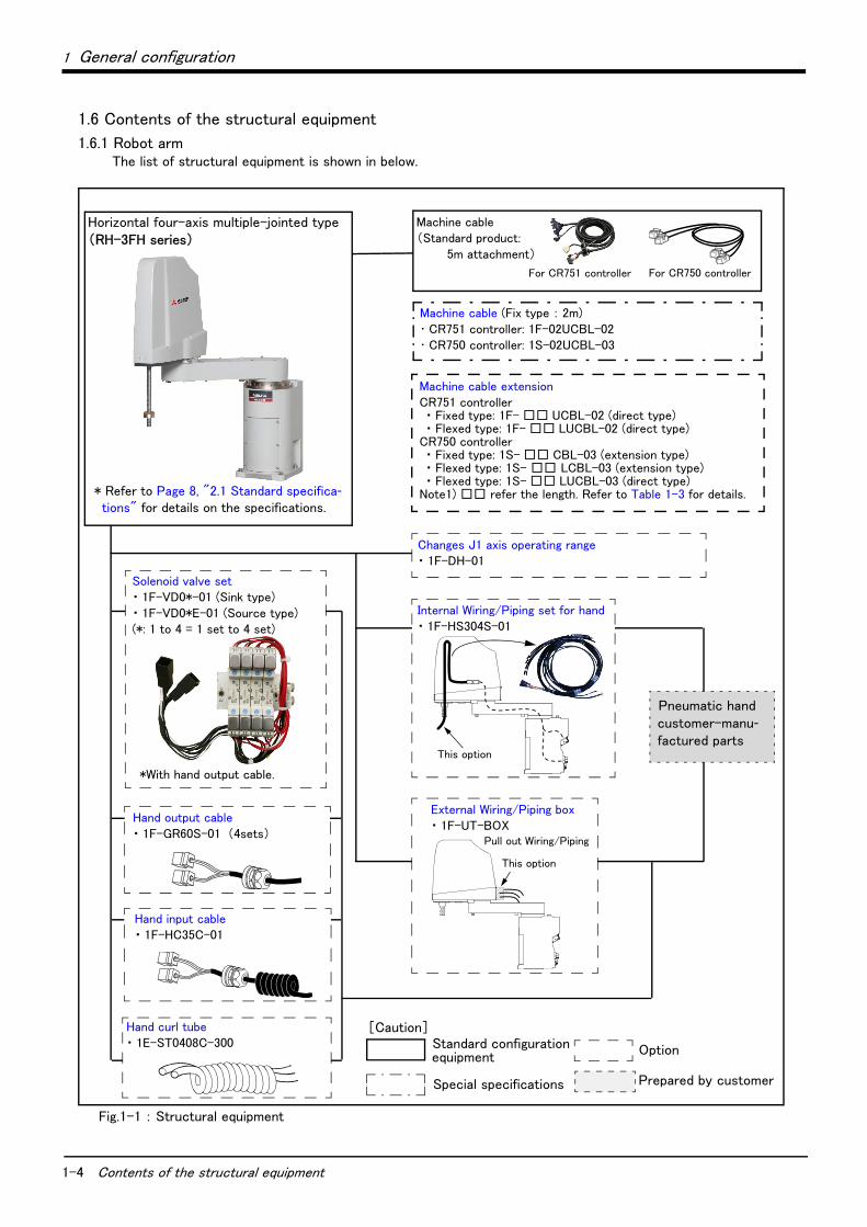
1.6 Contents of the structural equipment
1.6.1 Robot armThe list of structural equipment is shown in below.
Fig.1-1 : Structural equipment
* Refer to Page 8, "2.1 Standard specifica-tions" for details on the specifications.
Horizontal four-axis multiple-jointed type(RH-3FH series)
Hand output cable・ 1F-GR60S-01 (4sets)
Hand input cable・ 1F-HC35C-01
Hand curl tube・ 1E-ST0408C-300
Machine cable extensionCR751 controller・ Fixed type: 1F- □□ UCBL-02 (direct type)・ Flexed type: 1F- □□ LUCBL-02 (direct type)
CR750 controller・ Fixed type: 1S- □□ CBL-03 (extension type)・ Flexed type: 1S- □□ LCBL-03 (extension type)・ Flexed type: 1S- □□ LUCBL-03 (direct type)
Note1) □□ refer the length. Refer to Table 1-3 for details.
Machine cable (Fix type : 2m)・ CR751 controller: 1F-02UCBL-02・ CR750 controller: 1S-02UCBL-03
Solenoid valve set・ 1F-VD0*-01 (Sink type)・ 1F-VD0*E-01 (Source type)(*: 1 to 4 = 1 set to 4 set)
*With hand output cable.
Machine cable(Standard product:
5m attachment)
Pneumatic hand customer-manu-factured parts
[Caution]Standard configuration
Special specifications
Optionequipment
Prepared by customer
Changes J1 axis operating range・ 1F-DH-01
Internal Wiring/Piping set for hand・ 1F-HS304S-01
This option
External Wiring/Piping box・ 1F-UT-BOX
Pull out Wiring/Piping
This option
For CR751 controller For CR750 controller
1 General configuration
1-5
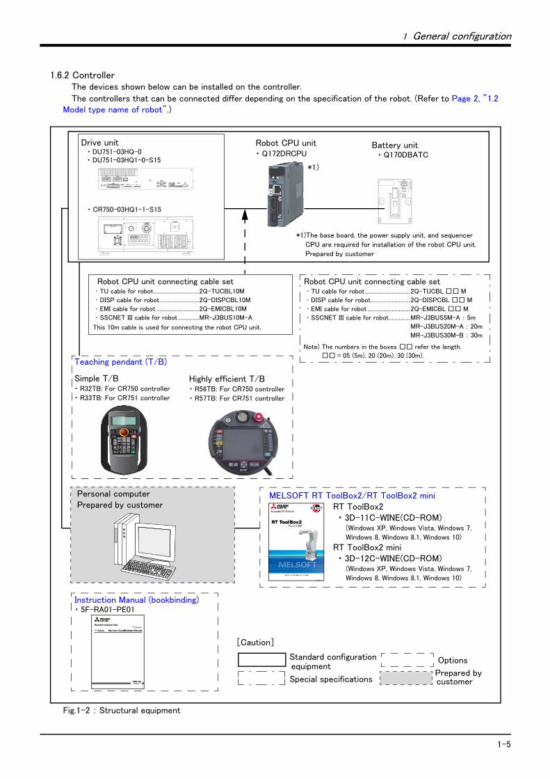
1.6.2 ControllerThe devices shown below can be installed on the controller.
The controllers that can be connected differ depending on the specification of the robot. (Refer to Page 2, "1.2 Model type name of robot".)
Fig.1-2 : Structural equipment
MELSOFT RT ToolBox2/RT ToolBox2 miniRT ToolBox2・ 3D-11C-WINE(CD-ROM)
(Windows XP, Windows Vista, Windows 7,
Windows 8, Windows 8.1, Windows 10)
RT ToolBox2 mini ・ 3D-12C-WINE(CD-ROM)
(Windows XP, Windows Vista, Windows 7,
Windows 8, Windows 8.1, Windows 10)
Instruction Manual (bookbinding)・ 5F-RA01-PE01
Teaching pendant (T/B)
Simple T/B・ R32TB: For CR750 controller
・ R33TB: For CR751 controller
Highly efficient T/B・ R56TB: For CR750 controller
・ R57TB: For CR751 controller
Robot CPU unit・ Q172DRCPU
Drive unit・ DU751-03HQ-0・ DU751-03HQ1-0-S15
Battery unit・ Q170DBATC
*1)The base board, the power supply unit, and sequencer
CPU are required for installation of the robot CPU unit.
Prepared by customer
Robot CPU unit connecting cable set ・ TU cable for robot ................................2Q-TUCBL10M
・ DISP cable for robot............................2Q-DISPCBL10M
・ EMI cable for robot ..............................2Q-EMICBL10M
・ SSCNET III cable for robot...............MR-J3BUS10M-A
This 10m cable is used for connecting the robot CPU unit.
*1)
・ CR750-03HQ1-1-S15
Robot CPU unit connecting cable set ・ TU cable for robot................................2Q-TUCBL □□ M
・ DISP cable for robot............................2Q-DISPCBL □□ M
・ EMI cable for robot ..............................2Q-EMICBL □□ M
・ SSCNET III cable for robot...............MR-J3BUS5M-A : 5m
MR-J3BUS20M-A : 20m
MR-J3BUS30M-B : 30m
Note) The numbers in the boxes □□ refer the length.
□□ = 05 (5m), 20 (20m), 30 (30m).
Personal computerPrepared by customer
Standard configuration
Special specifications
Options
Prepared by
[Caution]
equipment
customer
1-6 Contents of the Option equipment and special specification
1 General configuration
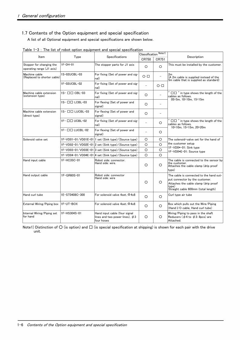
1.7 Contents of the Option equipment and special specification
A list of all Optional equipment and special specifications are shown below.
Table 1-3 : The list of robot option equipment and special specification
Item Type Specifications Classification Note1)
Note1) Distinction of ○ (is option) and □ (is special specification at shipping) is shown for each pair with the driveunit.
Description CR750 CR751
Stopper for changing the
operating range (J1 axis)
1F-DH-01 The stopper parts for J1 axis○ ○
This must be installed by the customer.
Machine cable (Replaced to shorter cable)
1S-02UCBL-03 For fixing (Set of power and sig-nal)
○・□ -2m(A 2m cable is supplied instead of the 5m cable that is supplied as standard)
1F-02UCBL-02 For fixing (Set of power and sig-nal)
- ○・□
Machine cable extension(extension type)
1S- □□ CBL-03 For fixing (Set of power and sig-nal)
○ -" □□ " in type shows the length of the cables as follows.
05=5m, 10=10m, 15=15m1S- □□ LCBL-03 For flexing (Set of power and
signal)○ -
Machine cable extension
(direct type)
1S- □□ LUCBL-03 For flexing (Set of power and
signal)○ -
1F- □□ UCBL-02 For fixing (Set of power and sig-nal)
- ○" □□ " in type shows the length of the cables as follows.
10=10m, 15=15m, 20=20m1F- □□ LUCBL-02 For flexing (Set of power and
signal)- ○
Solenoid valve set 1F-VD01-01/VD01E-01 1 set (Sink type)/(Source type) ○ ○ The solenoid-valve set for the hand of
the customer setup
1F-VD0*-01: Sink type
1F-VD0*E-01: Source type
1F-VD02-01/VD02E-01 2 set (Sink type)/(Source type) ○ ○
1F-VD03-01/VD03E-01 3 set (Sink type)/(Source type) ○ ○
1F-VD04-01/VD04E-01 4 set (Sink type)/(Source type) ○ ○
Hand input cable 1F-HC35C-01 Robot side: connector.Hand side: wire.
○ ○
The cable is connected to the sensor bythe customer.Attaches the cable clamp (drip proof
type)
Hand output cable 1F-GR60S-01 Robot side: connectorHand side: wire
○ ○
The cable is connected to the hand out-put connector by the customer.
Attaches the cable clamp (drip proof type)Straight cable 600mm (total length)
Hand curl tube 1E-ST0408C-300 For solenoid valve 4set.:Φ4x8○ ○
Curl type air tube
External Wiring/Piping box 1F-UT-BOX For solenoid valve 4set.:Φ4x8○ ○
Box which pulls out the Wire/Piping
(Hand I/O cable, Hand curl tube)
Internal Wiring/Piping set for hand
1F-HS304S-01 Hand input cable (four signal lines and two power lines), φ3 four hoses
○ ○Wiring/Piping to pass in the shaftReducers (φ4 to φ3: 8pcs) are Attached.
1 General configuration
Contents of the Option equipment and special specification 1-7
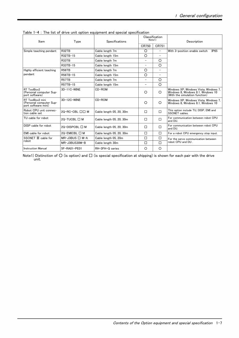
Table 1-4 : The list of drive unit option equipment and special specification
Item Type Specifications
Classification Note1)
Note1) Distinction of ○ (is option) and □ (is special specification at shipping) is shown for each pair with the driveunit.
Description
CR750 CR751
Simple teaching pendant R32TB Cable length 7m ○ - With 3-position enable switch IP65
R32TB-15 Cable length 15m ○ -
R33TB Cable length 7m - ○
R33TB-15 Cable length 15m - ○
Highly efficient teaching
pendant
R56TB Cable length 7m ○ -
R56TB-15 Cable length 15m ○ -
R57TB Cable length 7m - ○
R57TB-15 Cable length 15m - ○
RT ToolBox2(Personal computer Sup-port software)
3D-11C-WINE CD-ROM○ ○
Windows XP, Windows Vista, Windows 7, Windows 8, Windows 8.1, Windows 10(With the simulation function)
RT ToolBox2 mini(Personal computer Sup-port software mini)
3D-12C-WINE CD-ROM○ ○
Windows XP, Windows Vista, Windows 7, Windows 8, Windows 8.1, Windows 10
Robot CPU unit connec-tion cable set 2Q-RC-CBL □□ M Cable length 05, 20, 30m □ □ This option include TU, DISP, EMI and
SSCNET cables.
TU cable for robot 2Q-TUCBL □ M Cable length 05, 20, 30m □ □ For communication between robot CPU and DU.
DISP cable for robot 2Q-DISPCBL □ M Cable length 05, 20, 30m □ □ For communication between robot CPU and DU.
EMI cable for robot 2Q-EMICBL □ M Cable length 05, 20, 30m □ □ For a robot CPU emergency stop input.
SSCNET Ⅲ cable for robot
MR-J3BUS □ M-A Cable length 05, 20m □ □ For the servo communication between robot CPU and DU .MR-J3BUS30M-B Cable length 30m □ □
Instruction Manual 5F-RA01-PE01 RH-3FH-Q series ○ ○
2-8 Standard specifications
2Robot arm
2 Robot arm2.1 Standard specifications2.1.1 Basic specifications
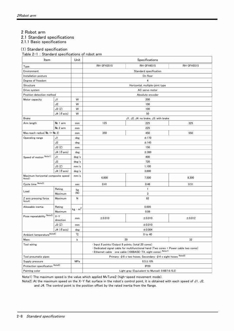
(1) Standard specificationTable 2-1 : Standard specifications of robot arm
Item Unit Specifications
Type RH-3FH3515 RH-3FH4515 RH-3FH5515
Environment Standard specification
Installation posture On floor
Degree of freedom 4
Structure Horizontal, multiple-joint type
Drive system AC servo motor
Position detection method Absolute encoder
Motor capacity J1 W 200
J2 W 100
J3 (Z) W 100
J4 (θaxis) W 50
Brake J1, J2, J4: no brake, J3: with brake
Arm length № 1 arm mm 125 225 325
№ 2 arm mm 225
Max.reach radius( № 1+ № 2) mm 350 450 550
Operating range J1 deg ±170
J2 deg ±145
J3 (Z) mm 150
J4 (θaxis) deg ±360
Speed of motion Note1)
Note1) The maximum speed is the value which applied MvTune2 (high-speed movement mode).
J1 deg/s 400
J2 deg/s 720
J3 (Z) mm/s 1,100
J4 (θaxis) deg/s 3,000
Maximum horizontal composite speed Note2)
Note2) At the maximum speed on the X-Y flat surface in the robot's control point, it is obtained with each speed of J1, J2,and J4. The control point is the position offset by the rated inertia from the flange.
mm/s6,800 7,500 8,300
Cycle time Note3) sec 0.41 0.46 0.51
LoadRating kg
(N)
1
Maximum 3
Z axis pressing forceNote4)
Maximum N 82
Allowable inertia Ratingkg ・ m2 0.005
Maximum 0.06
Pose repeatability Note5) X-Y
directionmm ±0.010 ±0.010 ±0.012
J3 (Z) mm ±0.010
J4 (θaxis) deg ±0.004
Ambient temperatureNote6) ℃ 0 to 40
Mass k 29 32
Tool wiring ・ Input 8 points/Output 8 points, (total 20 cores)
・ Dedicated signal cable for multifunctional hand (Two cores + Power cable two cores)
・ Ethernet cable one cable (100BASE-TX, eight cores) Note7)
Tool pneumatic pipes Primary: φ6 x two hoses, Secondary: φ4 x eight hoses Note8)
Supply pressure MPa 0.5±10%
Protection specification Note9) IP20
Painting color Light gray (Equivalent to Munsell: 0.6B7.6/0.2)
2Robot arm
Standard specifications 2-9
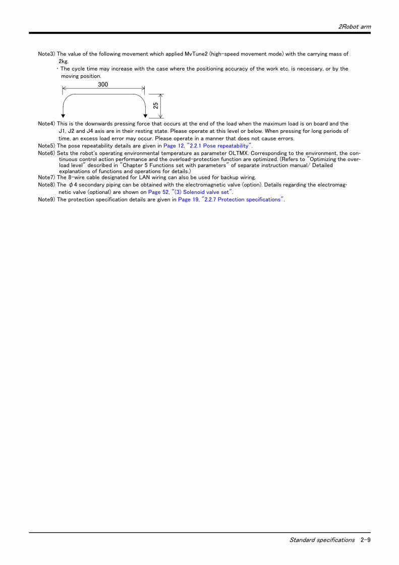
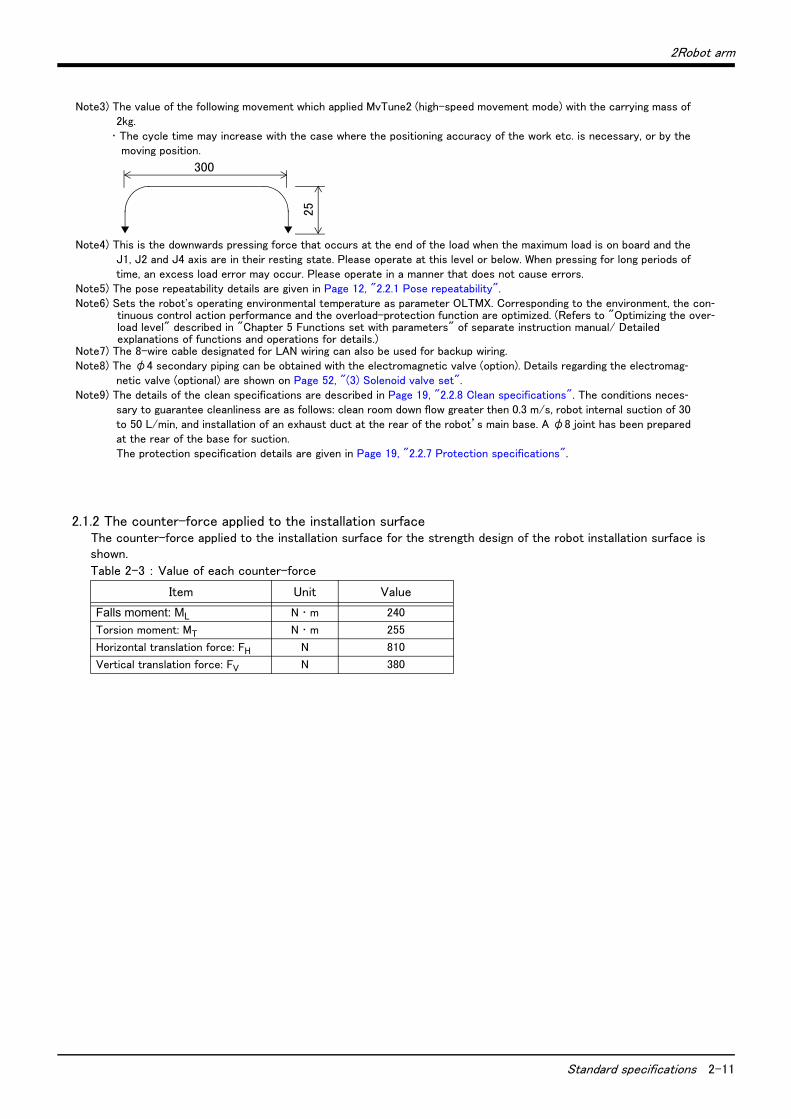
Note3) The value of the following movement which applied MvTune2 (high-speed movement mode) with the carrying mass of2kg.
・ The cycle time may increase with the case where the positioning accuracy of the work etc. is necessary, or by themoving position.
Note4) This is the downwards pressing force that occurs at the end of the load when the maximum load is on board and theJ1, J2 and J4 axis are in their resting state. Please operate at this level or below. When pressing for long periods oftime, an excess load error may occur. Please operate in a manner that does not cause errors.
Note5) The pose repeatability details are given in Page 12, "2.2.1 Pose repeatability".Note6) Sets the robot's operating environmental temperature as parameter OLTMX. Corresponding to the environment, the con-
tinuous control action performance and the overload-protection function are optimized. (Refers to "Optimizing the over-load level" described in "Chapter 5 Functions set with parameters" of separate instruction manual/ Detailed explanations of functions and operations for details.)
Note7) The 8-wire cable designated for LAN wiring can also be used for backup wiring.Note8) The φ4 secondary piping can be obtained with the electromagnetic valve (option). Details regarding the electromag-
netic valve (optional) are shown on Page 52, "(3) Solenoid valve set".Note9) The protection specification details are given in Page 19, "2.2.7 Protection specifications".
300
25
2-10 Standard specifications
2Robot arm
(2) Clean specification
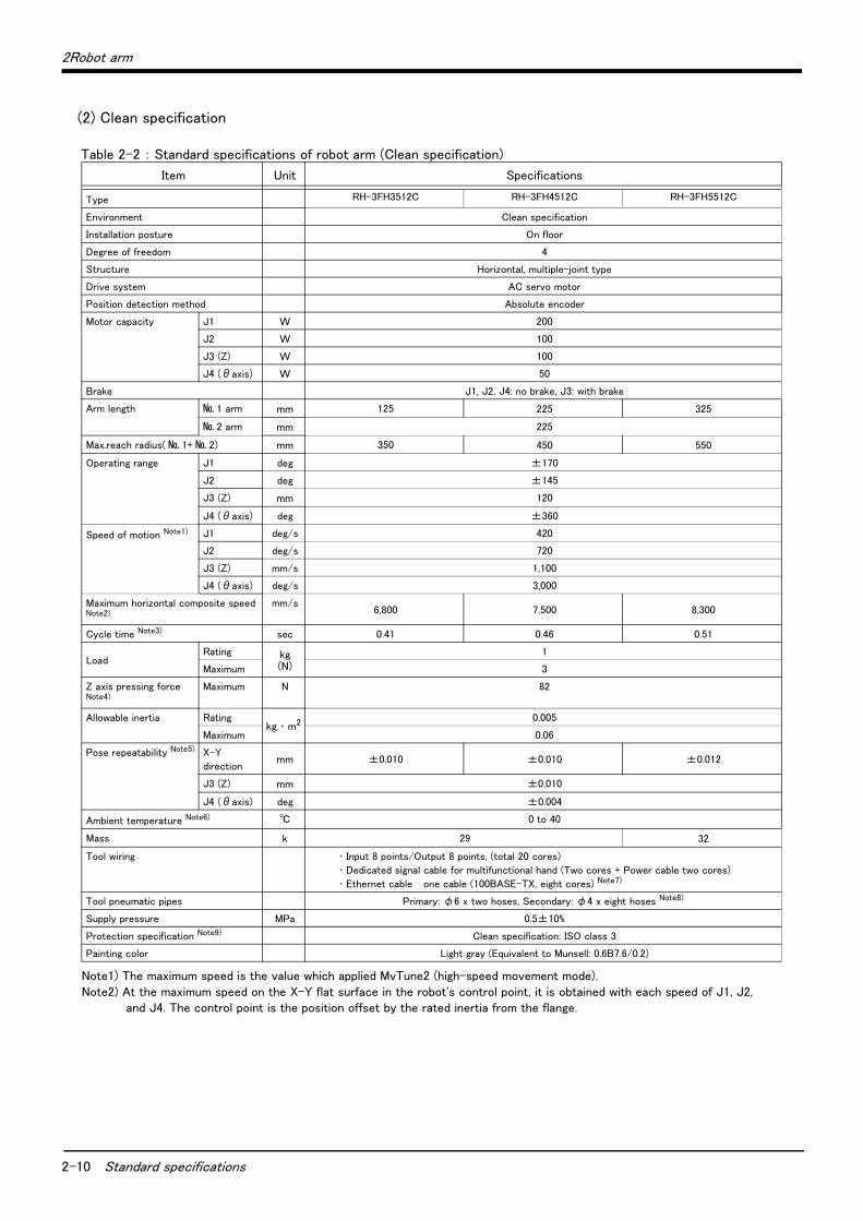
Table 2-2 : Standard specifications of robot arm (Clean specification)
Item Unit Specifications
Type RH-3FH3512C RH-3FH4512C RH-3FH5512C
Environment Clean specification
Installation posture On floor
Degree of freedom 4
Structure Horizontal, multiple-joint type
Drive system AC servo motor
Position detection method Absolute encoder
Motor capacity J1 W 200
J2 W 100
J3 (Z) W 100
J4 (θaxis) W 50
Brake J1, J2, J4: no brake, J3: with brake
Arm length № 1 arm mm 125 225 325
№ 2 arm mm 225
Max.reach radius( № 1+ № 2) mm 350 450 550
Operating range J1 deg ±170
J2 deg ±145
J3 (Z) mm 120
J4 (θaxis) deg ±360
Speed of motion Note1)
Note1) The maximum speed is the value which applied MvTune2 (high-speed movement mode).
J1 deg/s 420
J2 deg/s 720
J3 (Z) mm/s 1,100
J4 (θaxis) deg/s 3,000
Maximum horizontal composite speed Note2)
Note2) At the maximum speed on the X-Y flat surface in the robot's control point, it is obtained with each speed of J1, J2,and J4. The control point is the position offset by the rated inertia from the flange.
mm/s6,800 7,500 8,300
Cycle time Note3) sec 0.41 0.46 0.51
LoadRating kg
(N)
1
Maximum 3
Z axis pressing forceNote4)
Maximum N 82
Allowable inertia Ratingkg ・ m2 0.005
Maximum 0.06
Pose repeatability Note5) X-Y
directionmm ±0.010 ±0.010 ±0.012
J3 (Z) mm ±0.010
J4 (θaxis) deg ±0.004
Ambient temperature Note6) ℃ 0 to 40
Mass k 29 32
Tool wiring ・ Input 8 points/Output 8 points, (total 20 cores)
・ Dedicated signal cable for multifunctional hand (Two cores + Power cable two cores)
・ Ethernet cable one cable (100BASE-TX, eight cores) Note7)
Tool pneumatic pipes Primary: φ6 x two hoses, Secondary: φ4 x eight hoses Note8)
Supply pressure MPa 0.5±10%
Protection specification Note9) Clean specification: ISO class 3
Painting color Light gray (Equivalent to Munsell: 0.6B7.6/0.2)
2Robot arm
Standard specifications 2-11
2.1.2 The counter-force applied to the installation surfaceThe counter-force applied to the installation surface for the strength design of the robot installation surface is shown.
Table 2-3 : Value of each counter-force
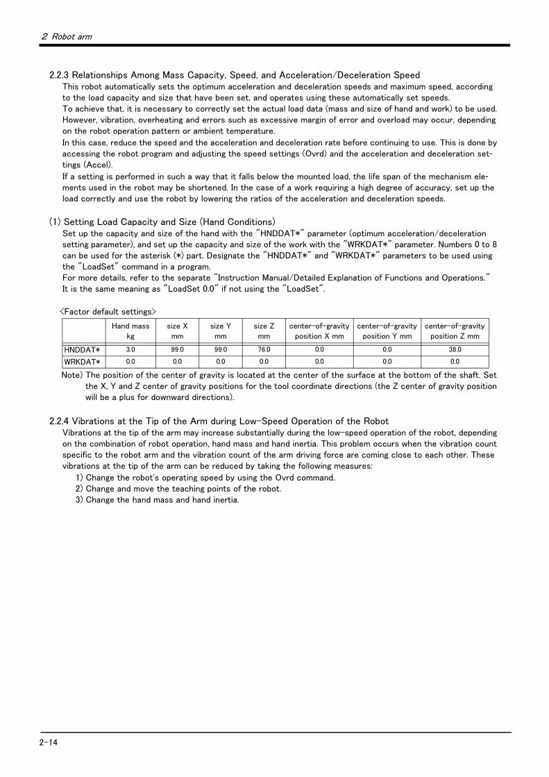
Note3) The value of the following movement which applied MvTune2 (high-speed movement mode) with the carrying mass of2kg.
・ The cycle time may increase with the case where the positioning accuracy of the work etc. is necessary, or by themoving position.
Note4) This is the downwards pressing force that occurs at the end of the load when the maximum load is on board and theJ1, J2 and J4 axis are in their resting state. Please operate at this level or below. When pressing for long periods oftime, an excess load error may occur. Please operate in a manner that does not cause errors.
Note5) The pose repeatability details are given in Page 12, "2.2.1 Pose repeatability".Note6) Sets the robot's operating environmental temperature as parameter OLTMX. Corresponding to the environment, the con-
tinuous control action performance and the overload-protection function are optimized. (Refers to "Optimizing the over-load level" described in "Chapter 5 Functions set with parameters" of separate instruction manual/ Detailed explanations of functions and operations for details.)
Note7) The 8-wire cable designated for LAN wiring can also be used for backup wiring.Note8) The φ4 secondary piping can be obtained with the electromagnetic valve (option). Details regarding the electromag-
netic valve (optional) are shown on Page 52, "(3) Solenoid valve set".Note9) The details of the clean specifications are described in Page 19, "2.2.8 Clean specifications". The conditions neces-
sary to guarantee cleanliness are as follows: clean room down flow greater then 0.3 m/s, robot internal suction of 30to 50 L/min, and installation of an exhaust duct at the rear of the robot’s main base. A φ8 joint has been preparedat the rear of the base for suction.The protection specification details are given in Page 19, "2.2.7 Protection specifications".
Item Unit Value
Falls moment: ML N ・ m 240
Torsion moment: MT N ・ m 255
Horizontal translation force: FH N 810
Vertical translation force: FV N 380
300
25
2-12 Definition of specifications
2 Robot arm
2.2 Definition of specifications
The accuracy of pose repeatability mentioned in catalogs and in the specification manual is defined as follows.
2.2.1 Pose repeatabilityFor this robot, the pose repeatability is given in accordance with JIS B 8432 (Pose repeatability). Note that the value is based on 100 measurements (although 30 measurements are required according to JIS).
[Caution] The specified "pose repeatability" is not guaranteed to be satisfied under the following conditions.
[1] Operation pattern factors1) When an operation that approaches from different directions and orientations are included in rela-
tion to the teaching position during repeated operations
2) When the speed at teaching and the speed at execution are different
[2] Load fluctuation factor1) When work is present/absent in repeated operations
[3] Disturbance factor during operation1) Even if approaching from the same direction and orientation to the teaching position, when the
power is turned OFF or a stop operation is performed halfway
[4] Temperature factors1) When the operating environment temperature changes
2) When accuracy is required before and after a warm-up operation
[5] Factors due to differences in accuracy definition1) When accuracy is required between a position set by a numeric value in the robot's internal coor-
dinate system and a position within the actual space
2) When accuracy is required between a position generated by the pallet function and a position within the actual space
2 Robot arm
2-13
2.2.2 Mass capacityThe robot's mass capacity is expressed solely in terms of mass, but even for tools and works of similar mass, eccentric loads will have some restrictions When designing the tooling or when selecting a robot, consider the fol-lowing issues.
(1) The tooling should have the value less or equal than the smaller of the allowable moment of inertia found in Page 8, "2.1.1 Basic specifications".
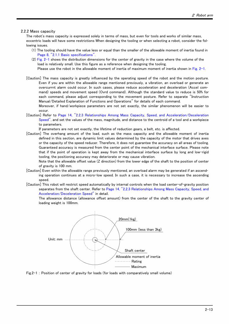
(2) Fig. 2-1 shows the distribution dimensions for the center of gravity in the case where the volume of the load is relatively small. Use this figure as a reference when designing the tooling. Please use the robot in the allowable moment of inertia of maximum moment of inertia shown in Fig. 2-1.
[Caution] The mass capacity is greatly influenced by the operating speed of the robot and the motion posture.Even if you are within the allowable range mentioned previously, a vibration, an overload or generate anovercurrnt alarm could occur. In such cases, please reduce acceleration and deceleration (Accel com-mand) speeds and movement speed (Ovrd command). Although the standard value to reduce is 50% foreach command, please adjust corresponding to the movement posture. Refer to separate "InstructionManual/Detailed Explanation of Functions and Operations" for details of each command.Moreover, if hand/workpiece parameters are not set exactly, the similar phenomenon will be easier tooccur.
[Caution] Refer to Page 14, "2.2.3 Relationships Among Mass Capacity, Speed, and Acceleration/DecelerationSpeed", and set the values of the mass, magnitude, and distance to the centroid of a tool and a workpieceto parameters.If parameters are not set exactly, the lifetime of reduction gears, a belt, etc. is affected.
[Caution] The overhang amount of the load, such as the mass capacity and the allowable moment of inertiadefined in this section, are dynamic limit values determined by the capacity of the motor that drives axesor the capacity of the speed reducer. Therefore, it does not guarantee the accuracy on all areas of tooling.Guaranteed accuracy is measured from the center point of the mechanical interface surface. Please notethat if the point of operation is kept away from the mechanical interface surface by long and low-rigidtooling, the positioning accuracy may deteriorate or may cause vibration. Note that the allowable offset value (Z direction) from the lower edge of the shaft to the position of centerof gravity is 100 mm.
[Caution] Even within the allowable range previously mentioned, an overload alarm may be generated if an ascend-ing operation continues at a micro-low speed. In such a case, it is necessary to increase the ascendingspeed.
[Caution] This robot will restrict speed automatically by internal controls when the load center-of-gravity positionseparates from the shaft center. Refer to Page 14, "2.2.3 Relationships Among Mass Capacity, Speed, andAcceleration/Deceleration Speed" in detail.The allowance distance (allowance offset amount) from the center of the shaft to the gravity center ofloading weight is 100mm.
Fig.2-1 : Position of center of gravity for loads (for loads with comparatively small volume)
定格慣性モーメント
最大慣性モーメント
シャフト中心
単位:mm
20mm(1kg)
100mm(3kg以下)
Unit: mm
Shaft center
Allowable moment of inertia
Maximum
Rating
100mm (less than 3kg)
2-14
2 Robot arm
2.2.3 Relationships Among Mass Capacity, Speed, and Acceleration/Deceleration SpeedThis robot automatically sets the optimum acceleration and deceleration speeds and maximum speed, according to the load capacity and size that have been set, and operates using these automatically set speeds. To achieve that, it is necessary to correctly set the actual load data (mass and size of hand and work) to be used. However, vibration, overheating and errors such as excessive margin of error and overload may occur, depending on the robot operation pattern or ambient temperature.
In this case, reduce the speed and the acceleration and deceleration rate before continuing to use. This is done by accessing the robot program and adjusting the speed settings (Ovrd) and the acceleration and deceleration set-tings (Accel).
If a setting is performed in such a way that it falls below the mounted load, the life span of the mechanism ele-ments used in the robot may be shortened. In the case of a work requiring a high degree of accuracy, set up the load correctly and use the robot by lowering the ratios of the acceleration and deceleration speeds.
(1) Setting Load Capacity and Size (Hand Conditions)Set up the capacity and size of the hand with the "HNDDAT*" parameter (optimum acceleration/deceleration setting parameter), and set up the capacity and size of the work with the "WRKDAT*" parameter. Numbers 0 to 8 can be used for the asterisk (*) part. Designate the "HNDDAT*" and "WRKDAT*" parameters to be used using the "LoadSet" command in a program. For more details, refer to the separate "Instruction Manual/Detailed Explanation of Functions and Operations."It is the same meaning as "LoadSet 0.0" if not using the "LoadSet".
<Factor default settings>
Note) The position of the center of gravity is located at the center of the surface at the bottom of the shaft. Set the X, Y and Z center of gravity positions for the tool coordinate directions (the Z center of gravity position will be a plus for downward directions).
2.2.4 Vibrations at the Tip of the Arm during Low-Speed Operation of the RobotVibrations at the tip of the arm may increase substantially during the low-speed operation of the robot, depending on the combination of robot operation, hand mass and hand inertia. This problem occurs when the vibration count specific to the robot arm and the vibration count of the arm driving force are coming close to each other. These vibrations at the tip of the arm can be reduced by taking the following measures:
1) Change the robot's operating speed by using the Ovrd command.2) Change and move the teaching points of the robot.3) Change the hand mass and hand inertia.
Hand masskg
size Xmm
size Ymm
size Zmm
center-of-gravity position X mm
center-of-gravity position Y mm
center-of-gravity position Z mm
HNDDAT* 3.0 99.0 99.0 76.0 0.0 0.0 38.0
WRKDAT* 0.0 0.0 0.0 0.0 0.0 0.0 0.0

2 Robot arm
2-15
2.2.5 Vibration of shaft (J3 axis) position and arm endVibrations at the tip of the arm may increase substantially during operation under the shaft position near the
low end or the high end of the robot, depending on the combination of hand mass and hand inertia. This problem occurs according to that inertia, because the distance from the shaft support section to the shaft end becomes long. When this vibration affects the robot's operations, please change operating speed etc. like the above Page 14, "2.2.4 Vibrations at the Tip of the Arm during Low-Speed Operation of the Robot".
(1) Relationship Between Mass Capacity and SpeedA function to optimize the maximum speed of each axis according to the setting value of the load capacity will be activated (Refer to Fig. 2-2).
However, this function does not work with the setting of 1kg or lighter load mass. When the load mass is changed to exceed 1kg, the maximum speed is compensated according to the load mass.
[CAUTION] Depending on the operation pattern, the speed and/or acceleration/deceleration at the front edge may not be parallel with the speed and the rate of change of acceleration/deceleration specified in a program.
Fig.2-2 : Automatic compensation of speed
100
60
00
1
最大速度割合
負荷質量(kg)
3
(%)
RH-3FH series
Max
imum
spe
ed r
atio
(%)
Load capacity (kg)
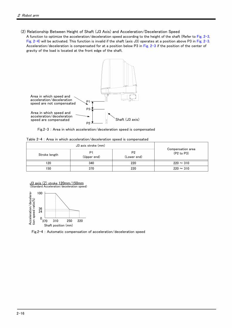
2-16
2 Robot arm
(2) Relationship Between Height of Shaft (J3 Axis) and Acceleration/Deceleration SpeedA function to optimize the acceleration/deceleration speed according to the height of the shaft (Refer to Fig. 2-3, Fig. 2-4) will be activated. This function is invalid if the shaft (axis J3) operates at a position above P3 in Fig. 2-3. Acceleration/deceleration is compensated for at a position below P3 in Fig. 2-3 if the position of the center of gravity of the load is located at the front edge of the shaft.
Fig.2-3 : Area in which acceleration/deceleration speed is compensated
Table 2-4 : Area in which acceleration/deceleration speed is compensated
Fig.2-4 : Automatic compensation of acceleration/deceleration speed
J3 axis stroke (mm)Compensation area
(P2 to P3)Stroke length P1
(Upper end)P2
(Lower end)
120 340 220 220 ~ 310
150 370 220 220 ~ 310
P3→
→シャフト(J3軸)
速度、加減速度を補正しない領域
速度、加減速度を補正する領域
P1
P2Shaft (J3 axis)
Area in which speed and acceleration/deceleration speed are not compensated
Area in which speed and acceleration/deceleration speed are compensated
加減速度割合
100
36
0370 310 220
シャフト位置(mm)
(%)
250
24
J3 axis (Z) stroke 120mm/150mm
Acc
ele
ration/de
cele
ra-
tion s
peed
ratio(%
)
Shaft position (mm)
(Standard Acceleration/deceleration speed)

2 Robot arm
2-17
(3) Relation between offset length and the maximum speedA function to optimize the maximum speed of each axis according to the offset length will be activated. (Refer to Fig. 2-5)
Fig.2-5 : Relationship of the offset length and maximum velocity
[Supplementary explanation 1]: The setting which shortens execution timeThe execution time can be improved by using the following methods.
1) Perform continuous path operation using the Cnt command.2) Control the optimum acceleration/deceleration using the Oadl command.3) Control the optimum speed using the Spd command.4) Setting a larger value in the optimum acceleration/deceleration adjustment rate parameter: JADL. (Maxi-
mum 100)The moving time can be shortened by setting a larger value in the optimum acceleration/deceleration adjustment rate parameter (JADL). In this robot, the acceleration/deceleration speed is initialized to allow continuous moving with a short wait time (setting of B in the Fig. 2-6).This setting is suited for continuous operations that have a short tact time, such as palletizing work.Conversely, if quick moves (short moving time) are required, such as L/UL work on machined parts, the acceleration/deceleration speed can be increased by initial setting (setting of A in the Fig. 2-6).However, please note that some setting values of acceleration/deceleration speed tend to cause overload and overheat errors. In such a case, extend the wait time, reduce the acceleration/deceleration speed, or decrease the moving speed.
Fig.2-6 : Relationship between Acceleration/deceleration Speed and Tact Time (Conceptual Drawing)
加減速度割合
100
42
00 100
オフセット量(mm)
(%)
40
60
60
Accele
ration/d
ecel
era
tion
speed
ratio(%
)
Offset length (mm)
Tact time/1 cycle Operation time
Wait time B
A
Increased acceleration/deceleration speed
x Accel instruction [%] x parameter JADL [%]
Acceleration/deceleration speed [m/sec2] = optimum acceleration/deceleration speed [m/sec2]
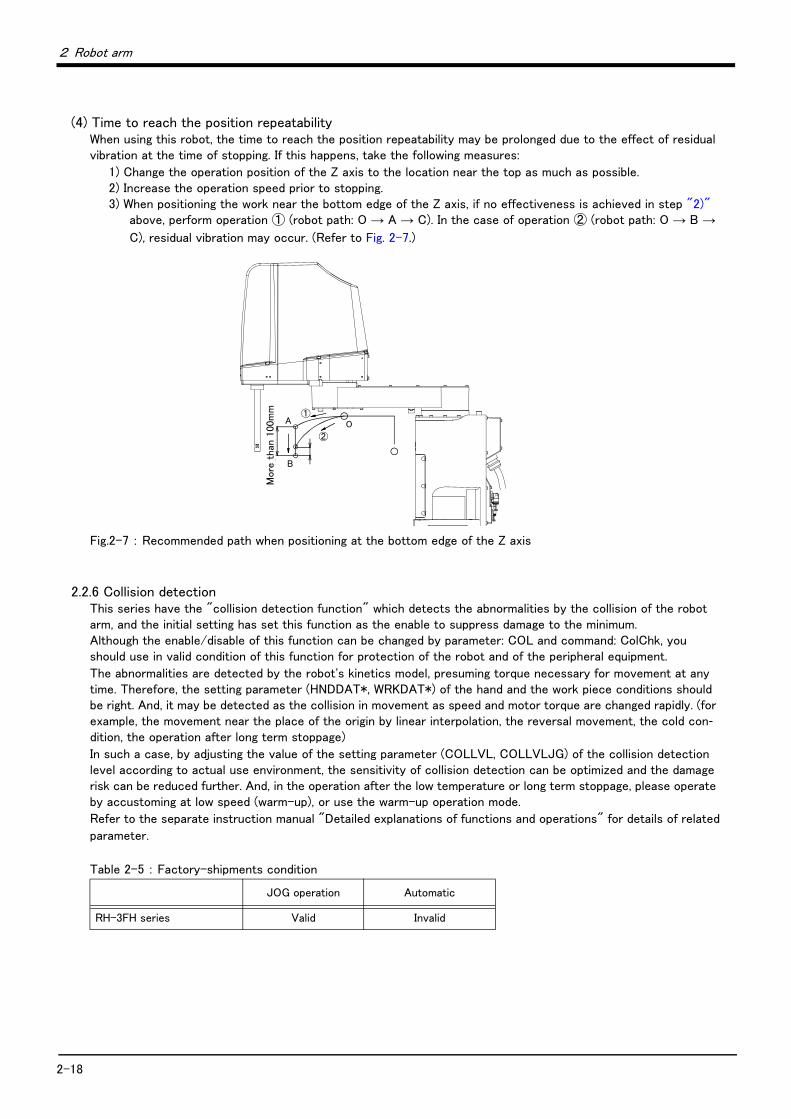
2-18
2 Robot arm
(4) Time to reach the position repeatabilityWhen using this robot, the time to reach the position repeatability may be prolonged due to the effect of residual vibration at the time of stopping. If this happens, take the following measures:
1) Change the operation position of the Z axis to the location near the top as much as possible.2) Increase the operation speed prior to stopping.3) When positioning the work near the bottom edge of the Z axis, if no effectiveness is achieved in step "2)"
above, perform operation ① (robot path: O → A → C). In the case of operation ② (robot path: O → B →
C), residual vibration may occur. (Refer to Fig. 2-7.)
Fig.2-7 : Recommended path when positioning at the bottom edge of the Z axis
2.2.6 Collision detectionThis series have the "collision detection function" which detects the abnormalities by the collision of the robot arm, and the initial setting has set this function as the enable to suppress damage to the minimum. Although the enable/disable of this function can be changed by parameter: COL and command: ColChk, you should use in valid condition of this function for protection of the robot and of the peripheral equipment.
The abnormalities are detected by the robot's kinetics model, presuming torque necessary for movement at any time. Therefore, the setting parameter (HNDDAT*, WRKDAT*) of the hand and the work piece conditions should be right. And, it may be detected as the collision in movement as speed and motor torque are changed rapidly. (for example, the movement near the place of the origin by linear interpolation, the reversal movement, the cold con-dition, the operation after long term stoppage)
In such a case, by adjusting the value of the setting parameter (COLLVL, COLLVLJG) of the collision detection level according to actual use environment, the sensitivity of collision detection can be optimized and the damage risk can be reduced further. And, in the operation after the low temperature or long term stoppage, please operate by accustoming at low speed (warm-up), or use the warm-up operation mode.
Refer to the separate instruction manual "Detailed explanations of functions and operations" for details of related
parameter.
Table 2-5 : Factory-shipments condition
JOG operation Automatic
RH-3FH series Valid Invalid
A
100mm以
上
B
②
①O
More
tha
n 100
mm
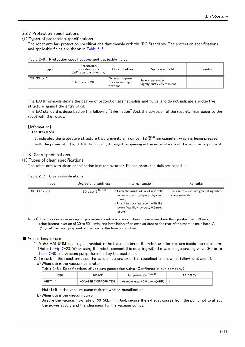
2 Robot arm
2-19
2.2.7 Protection specifications(1) Types of protection specifications
The robot arm has protection specifications that comply with the IEC Standards. The protection specifications and applicable fields are shown in Table 2-6.
Table 2-6 : Protection specifications and applicable fields
The IEC IP symbols define the degree of protection against solids and fluids, and do not indicate a protective structure against the entry of oil.
The IEC standard is described by the following "Information" And, the corrosion of the rust etc. may occur to the robot with the liquids.
【Information】
・ The IEC IP20
It indicates the protective structure that prevents an iron ball 12 0+0.05mm diameter, which is being pressed
with the power of 3.1 kg±10%, from going through the opening in the outer sheath of the supplied equipment.
2.2.8 Clean specifications(1) Types of clean specifications
The robot arm with clean specification is made by order. Please check the delivery schedule.
Table 2-7 : Clean specifications
■ Precautions for use1) A φ8 VACUUM coupling is provided in the base section of the robot arm for vacuum inside the robot arm.
(Refer to Fig. 2-23) When using the robot, connect this coupling with the vacuum generating valve (Refer to Table 2-8) and vacuum pump (furnished by the customer).
2) To suck in the robot arm, use the vacuum generator of the specification shown in following a) and b).a) When using the vacuum generator
Table 2-8 : Specifications of vacuum generation valve (Confirmed in our company)
b) When using the vacuum pump Assure the vacuum flow rate of 30-50L/min. And, secure the exhaust course from the pump not to affect the power supply and the cleanness for the vacuum pumps.
TypeProtection
specifications(IEC Standards value)
Classification Applicable field Remarks
RH-3FHxx15Robot arm: IP20
General-purpose environment speci-fications
General assemblySlightly dusty environment
Type Degree of cleanliness Internal suction Remarks
RH-3FHxx12C ISO class 3 Note1)
Note1) The conditions necessary to guarantee cleanliness are as follows: clean room down flow greater then 0.3 m/s, robot internal suction of 30 to 50 L/min, and installation of an exhaust duct at the rear of the robot’s main base. A φ8 joint has been prepared at the rear of the base for suction.
・ Suck the inside of robot arm with
vacuum pump. (prepared by cus-tomer)
・ Use it in the clean room with the
down flow (flow velocity 0.3 m/s
above).
The use of a vacuum generating valve
is recommended.
Type Maker Air pressure Note1)
Note1) It is the vacuum pump maker's written specification.
Quantity
MEDT 14 KOGANEI CORPORATION ・ Vacuum rate: 90.0 L/min(ANR) 1
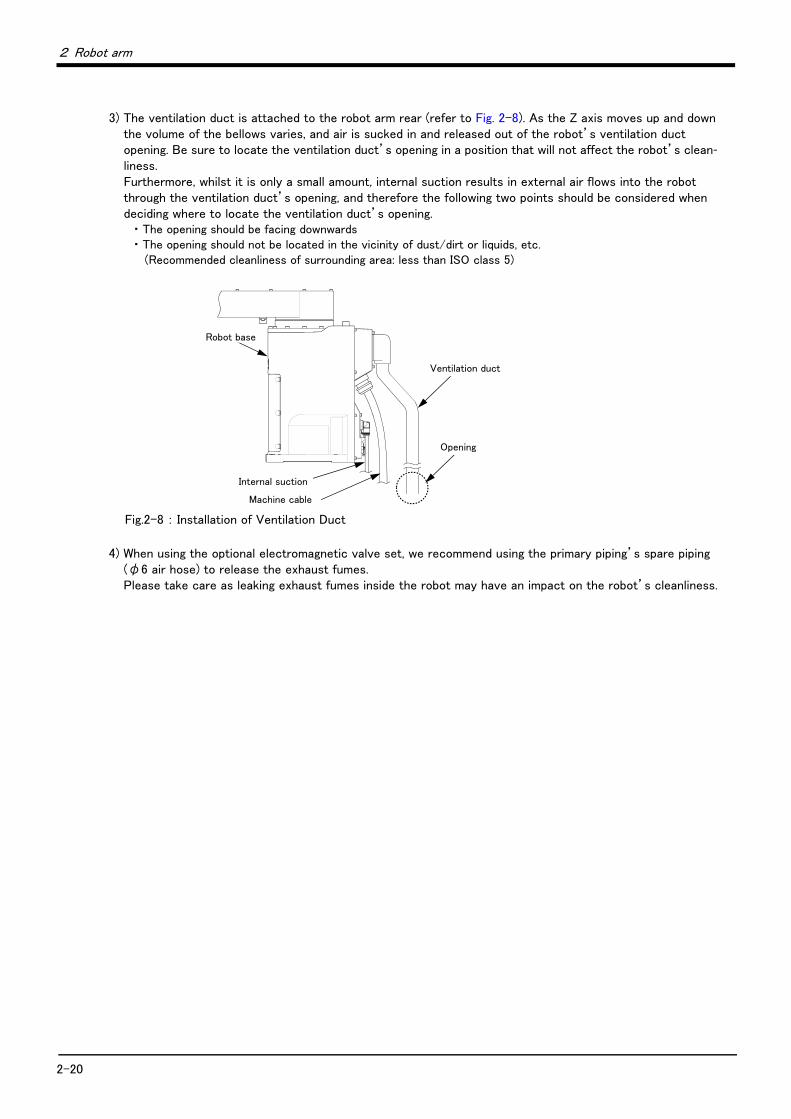
2-20
2 Robot arm
3) The ventilation duct is attached to the robot arm rear (refer to Fig. 2-8). As the Z axis moves up and down the volume of the bellows varies, and air is sucked in and released out of the robot’s ventilation duct opening. Be sure to locate the ventilation duct’s opening in a position that will not affect the robot’s clean-liness.Furthermore, whilst it is only a small amount, internal suction results in external air flows into the robot through the ventilation duct’s opening, and therefore the following two points should be considered when deciding where to locate the ventilation duct’s opening.
・ The opening should be facing downwards・ The opening should not be located in the vicinity of dust/dirt or liquids, etc.
(Recommended cleanliness of surrounding area: less than ISO class 5)
Fig.2-8 : Installation of Ventilation Duct
4) When using the optional electromagnetic valve set, we recommend using the primary piping’s spare piping (φ6 air hose) to release the exhaust fumes. Please take care as leaking exhaust fumes inside the robot may have an impact on the robot’s cleanliness.
Robot base
Internal suction
Opening
Machine cable
Ventilation duct

2 Robot arm
Names of each part of the robot 2-21
2.3 Names of each part of the robot
Fig.2-9 : Names of each part of the robot
ベース
第2アーム
J4軸
+-
J2軸
+-
J1軸
+-
第1アーム
J3軸
+
-
シャフト
ブレーキ解除スイッチ
ブレーキ解除スイッチView A
Note 1) The operation method of the brake release switch.The brake of J3 axis can be released with this switch and the enabling switch of T/B.Please be sure to perform brake release operation by two-person operations. Always assign an operator other than the switch operator to prevent the arm from dropping. This operation must be carried out with the switch operator giving signals.
When releasing the brake the J3 axis will drop. Be sure to perform brake release operation by two-person operations.
(1) One person supports so that the J3 axis may not drop.(2) The one more person pushes the brake release switch of the robot arm, in the
condition that the enabling switch of T/B is turned on.
CAUTION
Brake release switch
No.1 arm
No.2 arm
J1 axis
J2 axis
Base
J3 axis
Shaft
J4 axis
T/B
Enabling switch
(Hold down to the left or the right.)
Brake release switch
ANote1)
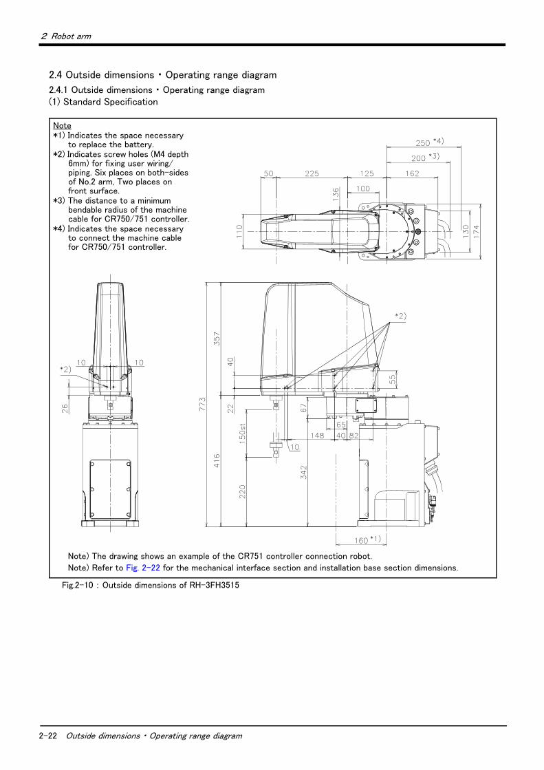
2-22 Outside dimensions ・ Operating range diagram
2 Robot arm
2.4 Outside dimensions ・ Operating range diagram
2.4.1 Outside dimensions ・ Operating range diagram(1) Standard Specification
Fig.2-10 : Outside dimensions of RH-3FH3515
Note*1) Indicates the space necessary
to replace the battery.*2) Indicates screw holes (M4 depth
6mm) for fixing user wiring/piping. Six places on both-sides of No.2 arm, Two places on front surface.
*3) The distance to a minimum bendable radius of the machine cable for CR750/751 controller.
*4) Indicates the space necessary to connect the machine cable for CR750/751 controller.
Note) The drawing shows an example of the CR751 controller connection robot.
Note) Refer to Fig. 2-22 for the mechanical interface section and installation base section dimensions.
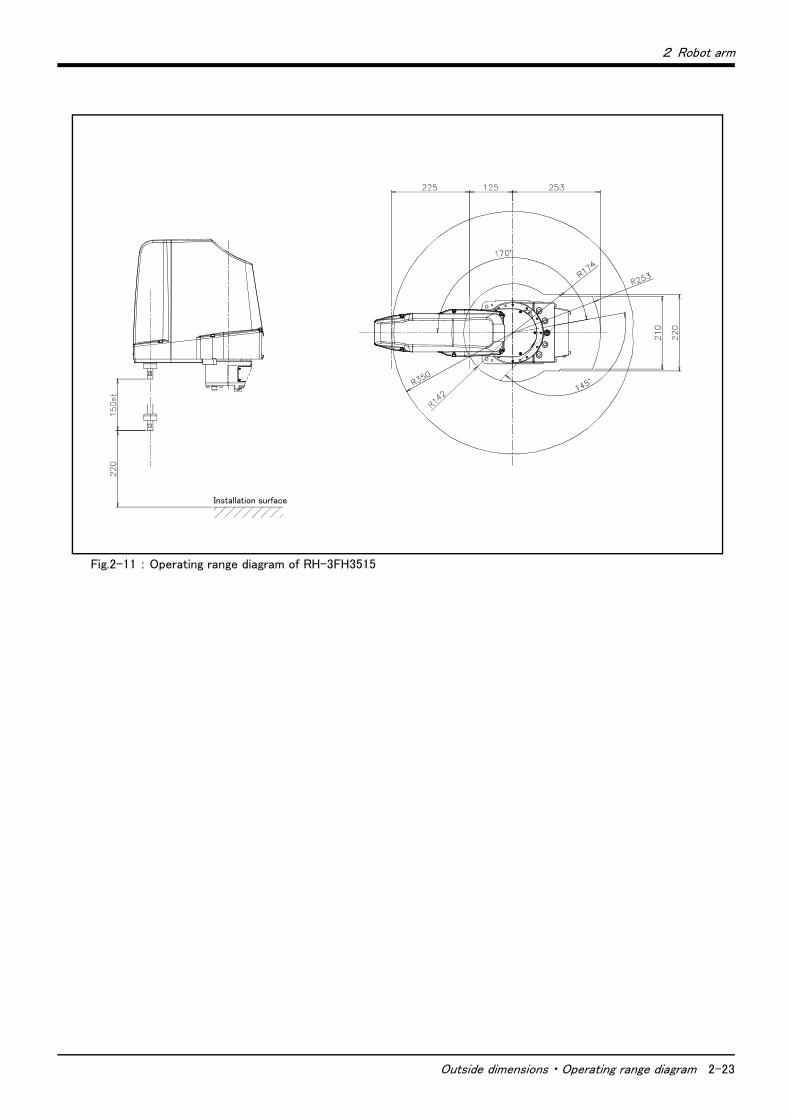
2 Robot arm
Outside dimensions ・ Operating range diagram 2-23
Fig.2-11 : Operating range diagram of RH-3FH3515
Installation surface
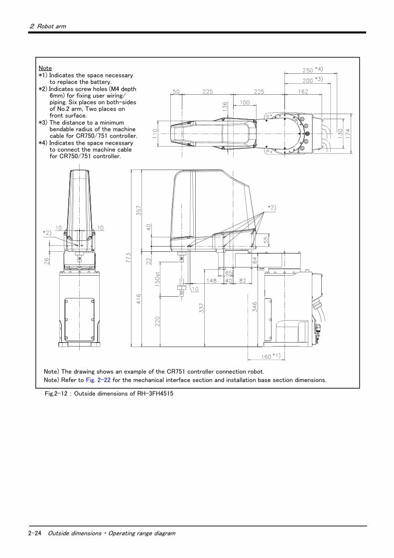
2-24 Outside dimensions ・ Operating range diagram
2 Robot arm
Fig.2-12 : Outside dimensions of RH-3FH4515
Note*1) Indicates the space necessary
to replace the battery.*2) Indicates screw holes (M4 depth
6mm) for fixing user wiring/piping. Six places on both-sides of No.2 arm, Two places on front surface.
*3) The distance to a minimum bendable radius of the machine cable for CR750/751 controller.
*4) Indicates the space necessary to connect the machine cable for CR750/751 controller.
Note) The drawing shows an example of the CR751 controller connection robot.
Note) Refer to Fig. 2-22 for the mechanical interface section and installation base section dimensions.
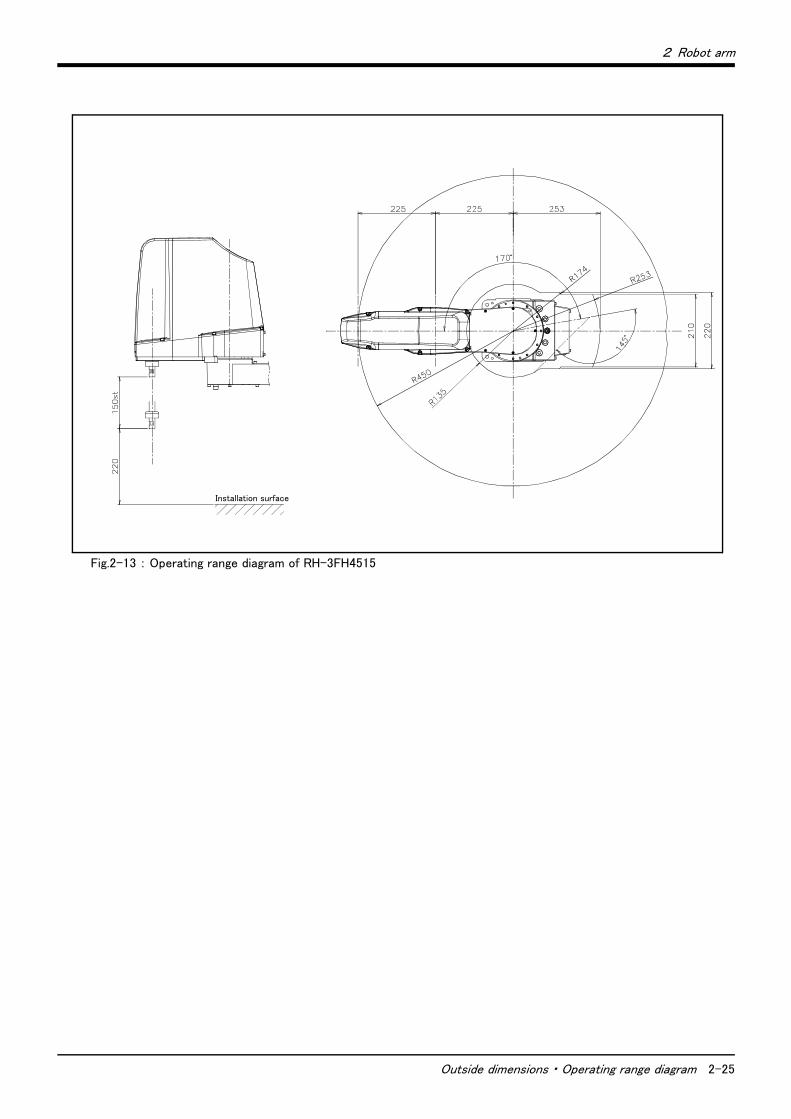
2 Robot arm
Outside dimensions ・ Operating range diagram 2-25
Fig.2-13 : Operating range diagram of RH-3FH4515
Installation surface
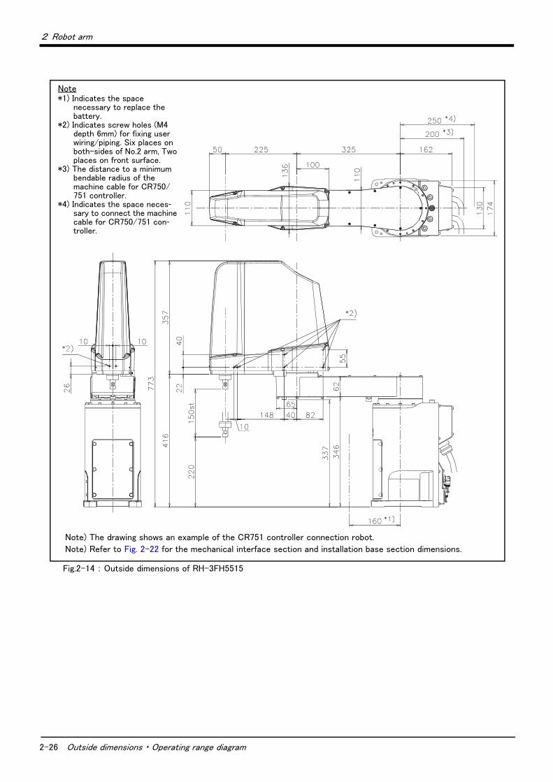
2-26 Outside dimensions ・ Operating range diagram
2 Robot arm
Fig.2-14 : Outside dimensions of RH-3FH5515
Note*1) Indicates the space
necessary to replace the battery.
*2) Indicates screw holes (M4 depth 6mm) for fixing user wiring/piping. Six places on both-sides of No.2 arm, Two places on front surface.
*3) The distance to a minimum bendable radius of the machine cable for CR750/751 controller.
*4) Indicates the space neces-sary to connect the machine cable for CR750/751 con-troller.
Note) The drawing shows an example of the CR751 controller connection robot.
Note) Refer to Fig. 2-22 for the mechanical interface section and installation base section dimensions.
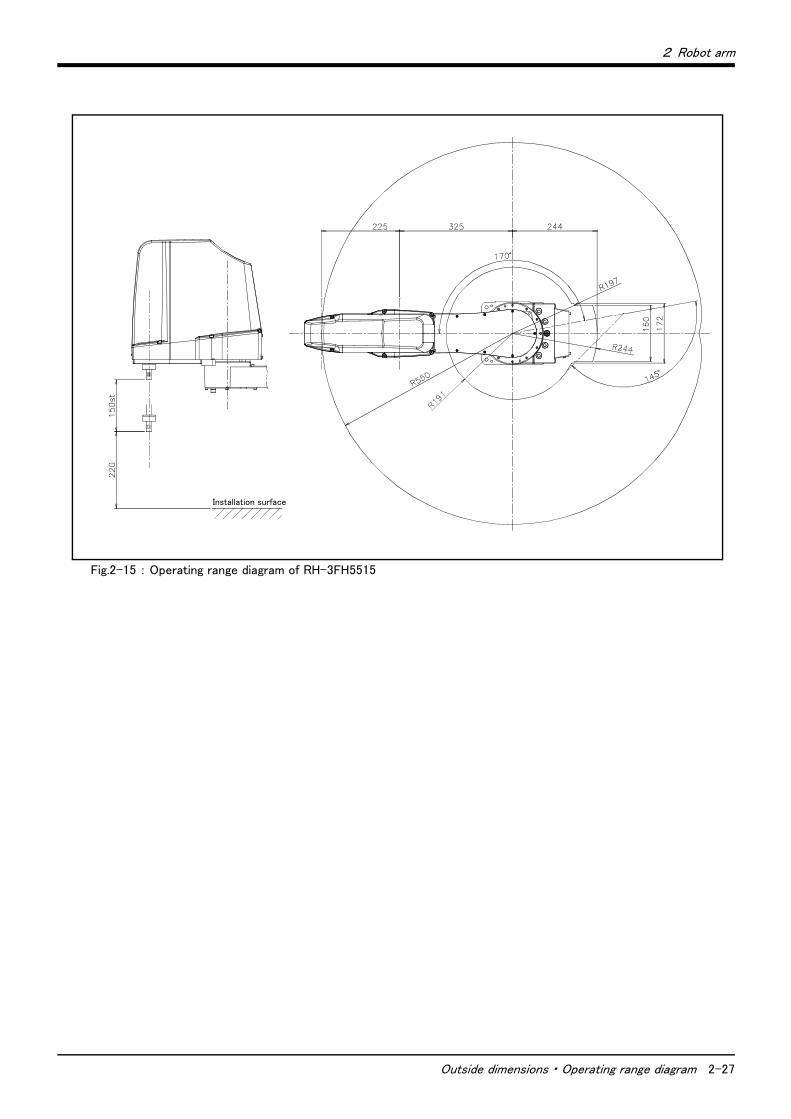
2 Robot arm
Outside dimensions ・ Operating range diagram 2-27
Fig.2-15 : Operating range diagram of RH-3FH5515
Installation surface
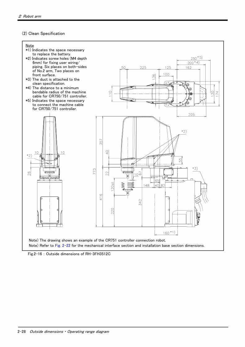
2-28 Outside dimensions ・ Operating range diagram
2 Robot arm
(2) Clean Specification
Fig.2-16 : Outside dimensions of RH-3FH3512C
Note*1) Indicates the space necessary
to replace the battery.*2) Indicates screw holes (M4 depth
6mm) for fixing user wiring/piping. Six places on both-sides of No.2 arm, Two places on front surface.
*3) The duct is attached to the clean specification.
*4) The distance to a minimum bendable radius of the machine cable for CR750/751 controller.
*5) Indicates the space necessary to connect the machine cable for CR750/751 controller.
Note) The drawing shows an example of the CR751 controller connection robot.
Note) Refer to Fig. 2-22 for the mechanical interface section and installation base section dimensions.
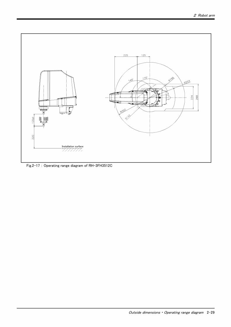
2 Robot arm
Outside dimensions ・ Operating range diagram 2-29
Fig.2-17 : Operating range diagram of RH-3FH3512C
Installation surface
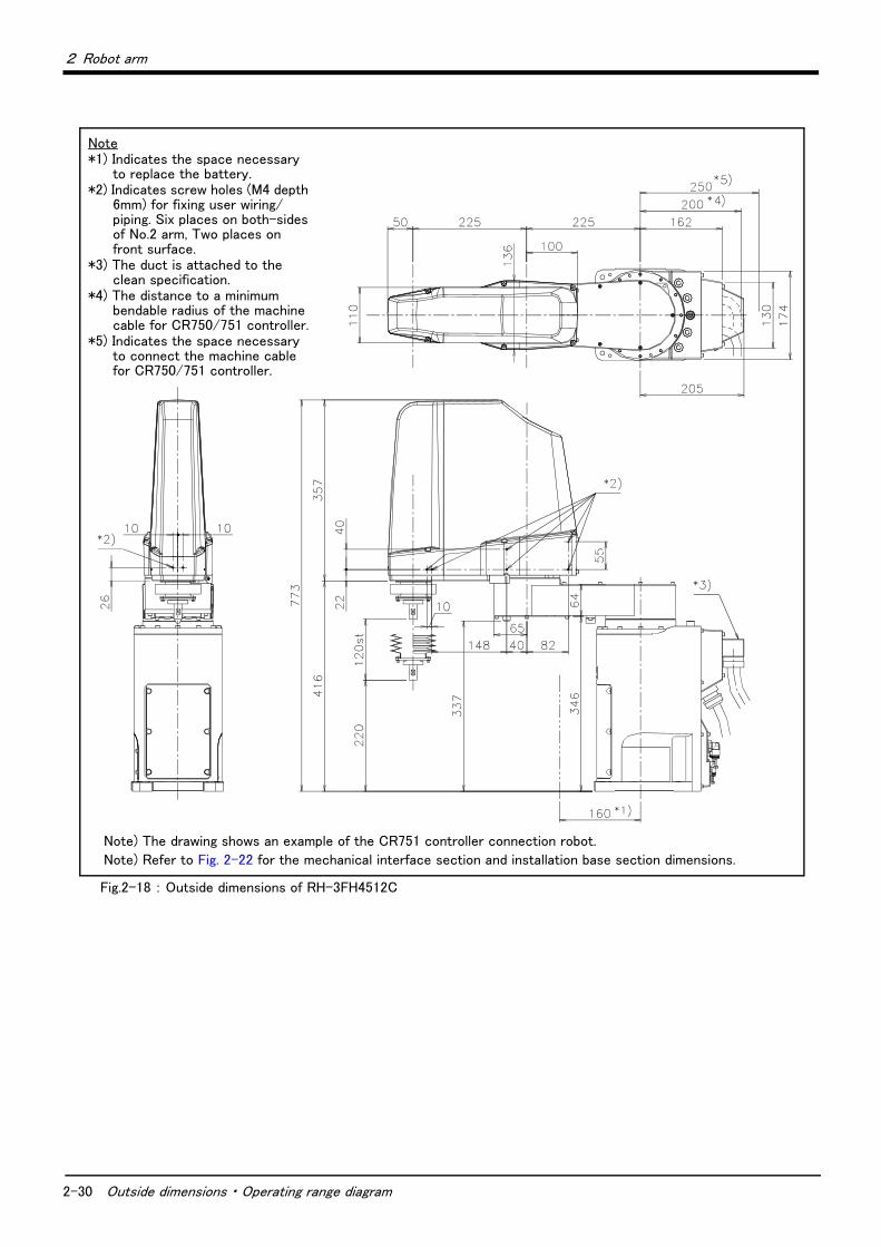
2-30 Outside dimensions ・ Operating range diagram
2 Robot arm
Fig.2-18 : Outside dimensions of RH-3FH4512C
Note*1) Indicates the space necessary
to replace the battery.*2) Indicates screw holes (M4 depth
6mm) for fixing user wiring/piping. Six places on both-sides of No.2 arm, Two places on front surface.
*3) The duct is attached to the clean specification.
*4) The distance to a minimum bendable radius of the machine cable for CR750/751 controller.
*5) Indicates the space necessary to connect the machine cable for CR750/751 controller.
Note) The drawing shows an example of the CR751 controller connection robot.
Note) Refer to Fig. 2-22 for the mechanical interface section and installation base section dimensions.
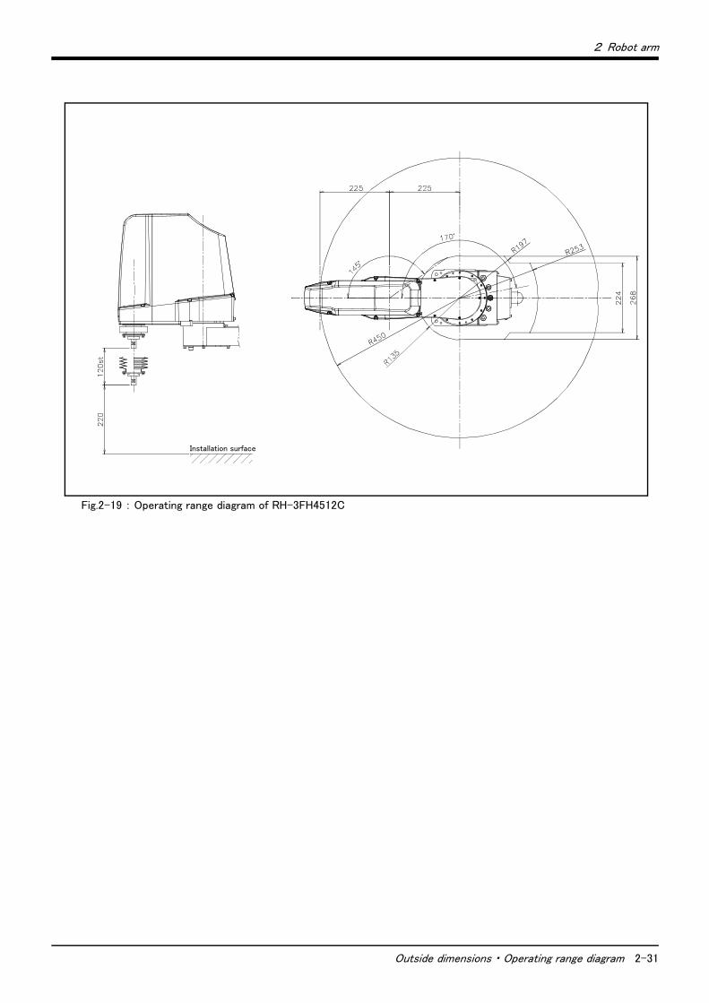
2 Robot arm
Outside dimensions ・ Operating range diagram 2-31
Fig.2-19 : Operating range diagram of RH-3FH4512C
Installation surface
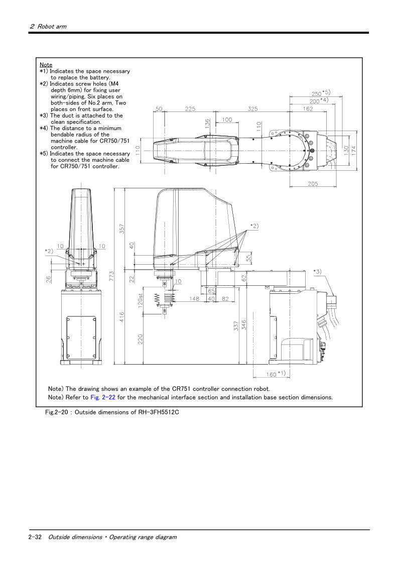
2-32 Outside dimensions ・ Operating range diagram
2 Robot arm
Fig.2-20 : Outside dimensions of RH-3FH5512C
Note*1) Indicates the space necessary
to replace the battery.*2) Indicates screw holes (M4
depth 6mm) for fixing user wiring/piping. Six places on both-sides of No.2 arm, Two places on front surface.
*3) The duct is attached to the clean specification.
*4) The distance to a minimum bendable radius of the machine cable for CR750/751 controller.
*5) Indicates the space necessary to connect the machine cable for CR750/751 controller.
Note) The drawing shows an example of the CR751 controller connection robot.
Note) Refer to Fig. 2-22 for the mechanical interface section and installation base section dimensions.
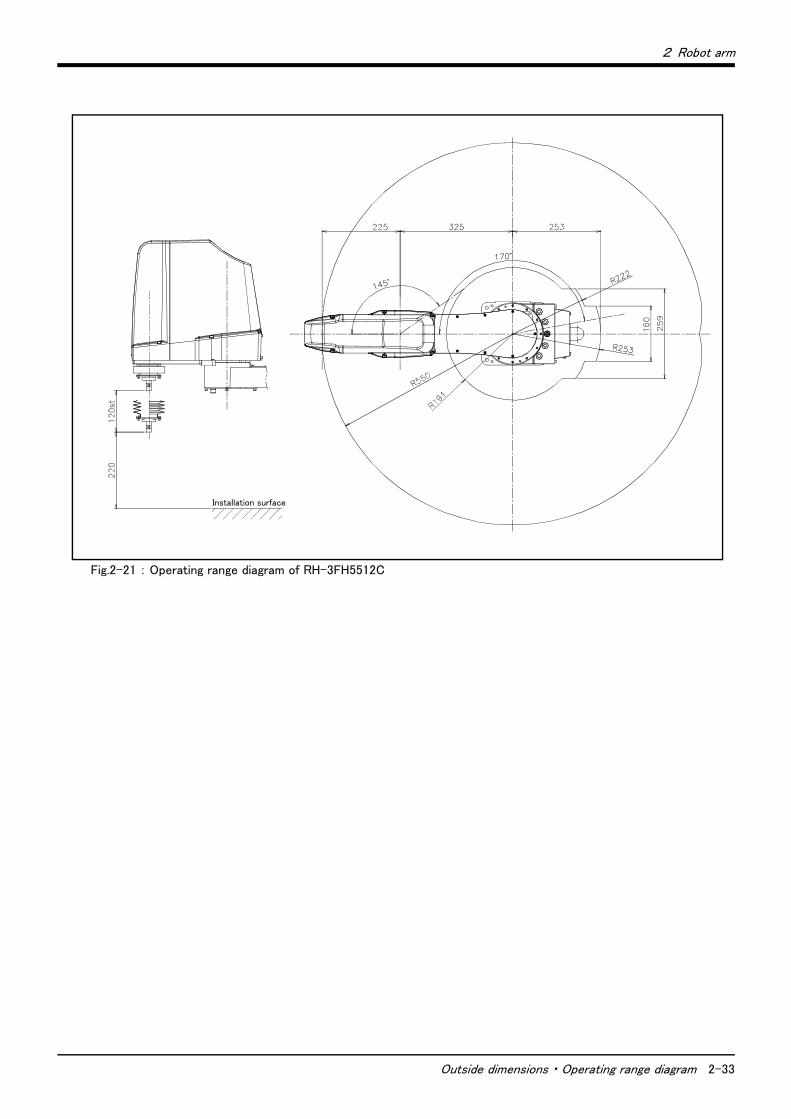
2 Robot arm
Outside dimensions ・ Operating range diagram 2-33
Fig.2-21 : Operating range diagram of RH-3FH5512C
Installation surface
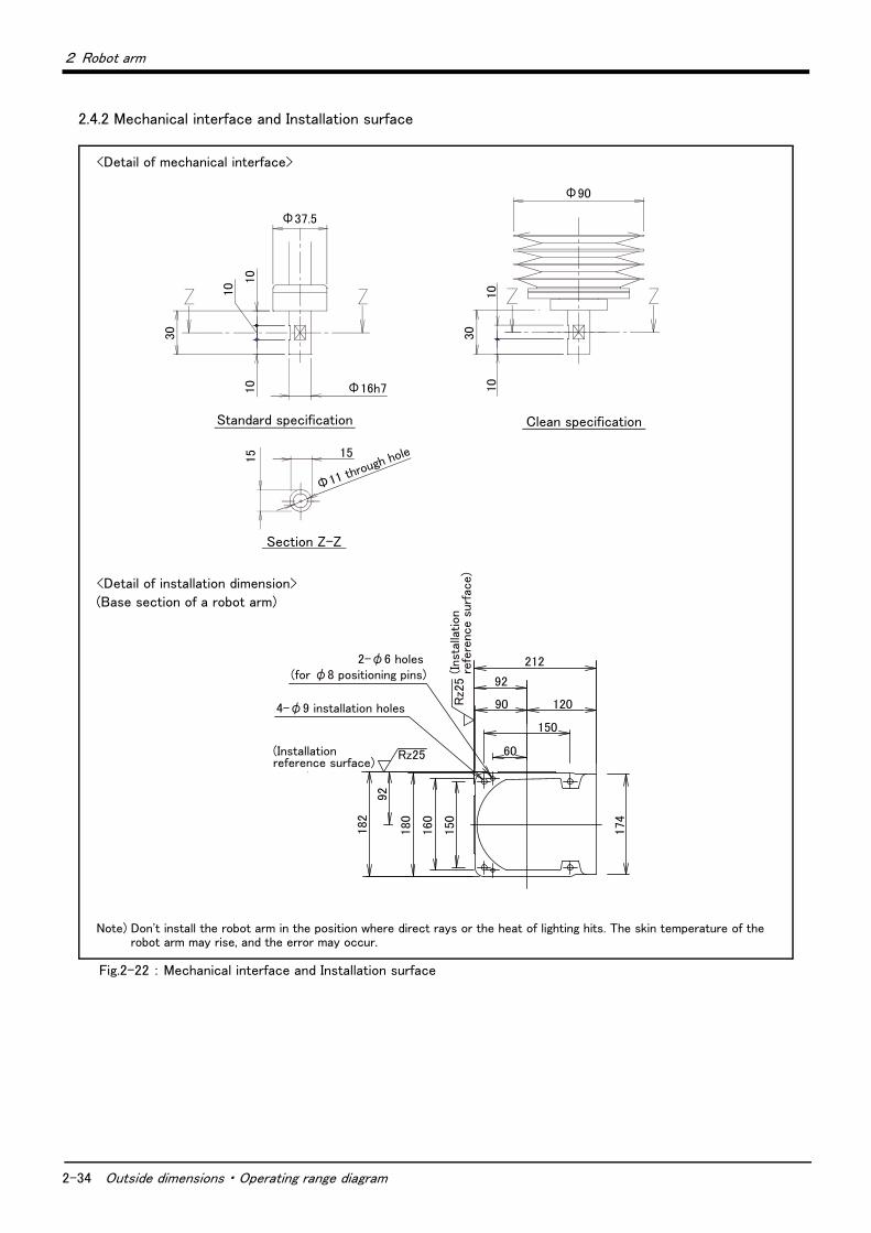
2-34 Outside dimensions ・ Operating range diagram
2 Robot arm
2.4.2 Mechanical interface and Installation surface
Fig.2-22 : Mechanical interface and Installation surface
Note) Don't install the robot arm in the position where direct rays or the heat of lighting hits. The skin temperature of the robot arm may rise, and the error may occur.
<Detail of installation dimension>
(Base section of a robot arm)
<Detail of mechanical interface>
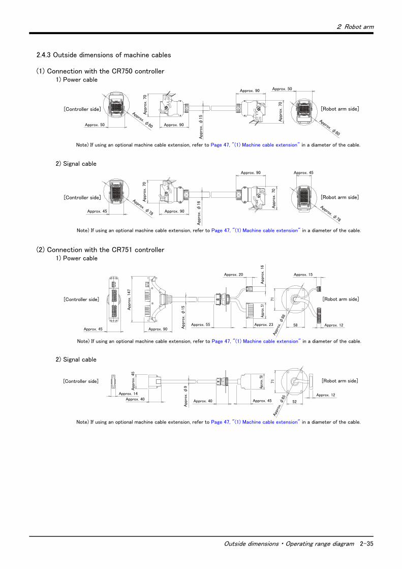
2 Robot arm
Outside dimensions ・ Operating range diagram 2-35
2.4.3 Outside dimensions of machine cables
(1) Connection with the CR750 controller1) Power cable
2) Signal cable
(2) Connection with the CR751 controller1) Power cable
2) Signal cable
Approx. φ80
[Controller side] [Robot arm side]
Approx. 50
Appr
ox.
70
Approx. 90
Appr
ox.
φ15
Approx. 90
Appr
ox.
70
Approx. 50
Approx. φ80
Note) If using an optional machine cable extension, refer to Page 47, "(1) Machine cable extension" in a diameter of the cable.
Approx. φ78
App
rox.
70
App
rox.
70
Approx. 90
Approx. 90
App
rox.
φ16
[Controller side] [Robot arm side]
Approx. 45
Approx. φ78
Approx. 45
Note) If using an optional machine cable extension, refer to Page 47, "(1) Machine cable extension" in a diameter of the cable.
App
rox. φ
88
[Controller side] [Robot arm side]
58
71
Approx. 15
Approx. 45 Approx. 90
Appro
x. 1
47
Appro
x. φ
15
Approx. 55 Approx. 23 Approx. 12
Appro
x. 1
6
Approx. 20
Note) If using an optional machine cable extension, refer to Page 47, "(1) Machine cable extension" in a diameter of the cable.
[Controller side] [Robot arm side]
Appro
x. φ
9
Approx. 45
71
52
Approx. 12
App
rox. φ
85
Approx. 14
Appro
x. 4
5
Approx. 40 Approx. 40
Note) If using an optional machine cable extension, refer to Page 47, "(1) Machine cable extension" in a diameter of the cable.
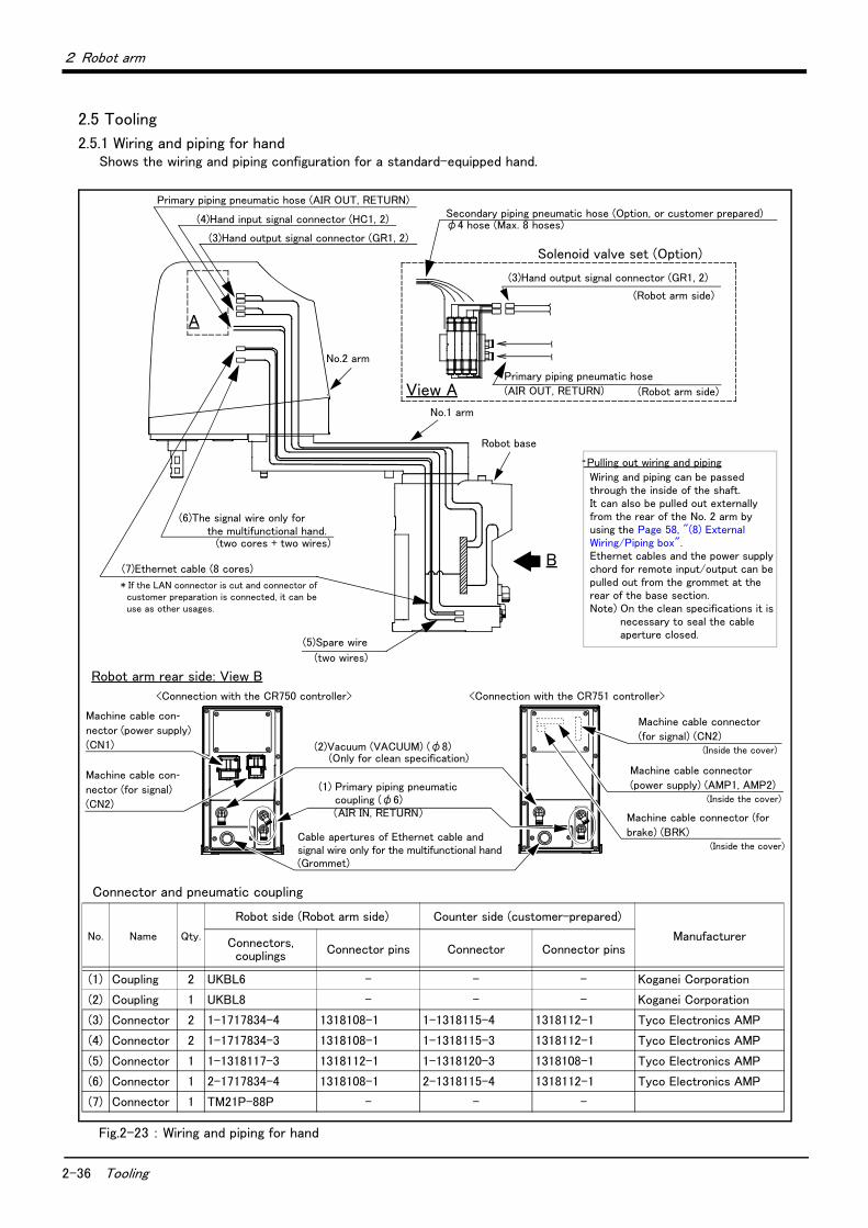
2-36 Tooling
2 Robot arm
2.5 Tooling
2.5.1 Wiring and piping for handShows the wiring and piping configuration for a standard-equipped hand.
Fig.2-23 : Wiring and piping for hand
Connector and pneumatic coupling
No. Name Qty.
Robot side (Robot arm side) Counter side (customer-prepared)
ManufacturerConnectors, couplings Connector pins Connector Connector pins
(1) Coupling 2 UKBL6 - - - Koganei Corporation
(2) Coupling 1 UKBL8 - - - Koganei Corporation
(3) Connector 2 1-1717834-4 1318108-1 1-1318115-4 1318112-1 Tyco Electronics AMP
(4) Connector 2 1-1717834-3 1318108-1 1-1318115-3 1318112-1 Tyco Electronics AMP
(5) Connector 1 1-1318117-3 1318112-1 1-1318120-3 1318108-1 Tyco Electronics AMP
(6) Connector 1 2-1717834-4 1318108-1 2-1318115-4 1318112-1 Tyco Electronics AMP
(7) Connector 1 TM21P-88P - - -
View A
A
(4)Hand input signal connector (HC1, 2)
(3)Hand output signal connector (GR1, 2)
Secondary piping pneumatic hose (Option, or customer prepared)φ4 hose (Max. 8 hoses)
Primary piping pneumatic hose (AIR OUT, RETURN)
Solenoid valve set (Option)
(3)Hand output signal connector (GR1, 2)
Primary piping pneumatic hose
(AIR OUT, RETURN)
(6)The signal wire only for the multifunctional hand.
(7)Ethernet cable (8 cores)
(5)Spare wire
* If the LAN connector is cut and connector of customer preparation is connected, it can be use as other usages.
Pulling out wiring and piping
Wiring and piping can be passed through the inside of the shaft. It can also be pulled out externally from the rear of the No. 2 arm by using the Page 58, "(8) External Wiring/Piping box".Ethernet cables and the power supply chord for remote input/output can be pulled out from the grommet at the rear of the base section.Note) On the clean specifications it is
necessary to seal the cable aperture closed.
(Robot arm side)
(Robot arm side)
No.2 arm
No.1 arm
Robot base
(two cores + two wires)
(two wires)
(1) Primary piping pneumatic coupling (φ6)(AIR IN, RETURN)
Cable apertures of Ethernet cable and signal wire only for the multifunctional hand (Grommet)
Machine cable connector
(power supply) (AMP1, AMP2)(Inside the cover)
Machine cable connector
(for signal) (CN2)(Inside the cover)(2)Vacuum (VACUUM) (φ8)
(Only for clean specification)
Machine cable connector (for
brake) (BRK)(Inside the cover)
<Connection with the CR750 controller>
Machine cable con-nector (for signal)
(CN2)
Machine cable con-nector (power supply)
(CN1)
Robot arm rear side: View B
<Connection with the CR751 controller>
B
2 Robot arm
Tooling 2-37
2.5.2 Internal air piping(1) Standard type
1) The robot has two φ6 urethane hoses from the pneumatic entrance on the base section to the No.2 arm. One hose is the primary piping for the pneumatic equipment, and the other pipe is used for air exhaust.
2) The pneumatic inlet in the base section has a φ6 pneumatic coupling bridge.3) The solenoid valve set (optional) can be installed to the side on No.2 arm.4) Refer to Page 52, "(3) Solenoid valve set" for details on the electronic valve set (optional).
(2) Clean type1) The primary piping is the same piping as the standard type.2) With the clean specification, a φ8 coupling is provided in the base section for suction inside the machine.
For use, connect it to the suction port of the vacuum pump or the coupling on the "VACUUM" side of the vacuum generating valve. Moreover, to clean the exhaust from the vacuum pump or vacuum generator, use the exhaust filter (prepared by the customer).
3) Refer to Page 19, "2.2.8 Clean specifications" for details of the vacuum for suction.4) Supply clean air to the vacuum generator.
2.5.3 Internal wiring for the hand output cable1) The hand output primary cable extends from the connector PCB of the base section to the back side of the
No.2 arm. (AWG#24(0.2mm2): 10 cables) The cable terminals have connector bridges for eight hand out-puts.The connector names are GR1 and GR2. To pull the wiring out of the arm, following separate options are required.
・ Hand output cable ....................................1F-GR60S-01
・ External wiring and piping box .............1F-UT-BOX
2.5.4 Internal wiring for the hand input cable1) The hand input cable extends from the connector PCB of the base section to the No.2 arm.
(AWG#24(0.2mm2): 10 cables) The cable terminals have connector bridges for eight hand inputs. The con-nector names are HC1 and HC2.
2) The hand check signal of the pneumatic hand is input by connecting this connector.To extend the wiring to the outside of the arm, following separate options are required.
・ Hand input cable .......................................1F-HC35C-01
・ External wiring and piping box .............1F-UT-BOX
2.5.5 Ethernet cable Ethernet cables are installed from the robot’s base section up to the No. 2 arm section, and can be used.
Similar to on our previous models, these cables can also be used for backup wiring. For further details please refer to the separate “Instruction Manual/Robot Arm Setup”.
Example of use for backup wiring.
・ When connecting previously used tools to the robot
・ Folding back the hand output cable when attaching the electromagnetic valve to the robot’s exterior.
・ When attaching 8 devices or more to the hand section such as sensors, (8 input and 8 output dedicated points are available for hand signals.). In this case connect the signals (of the sensors, etc.) to parallel input/output signals.
When shipped from the factory, both ends are LAN connectors.
When using it as backup wiring, cut the LAN connectors off and use with user supplied connectors.
When using it as backup wiring for data communication, the shield wire must be grounded. If the shield wire is not grounded, it may cause a communication abnormality by noise superposed on the cable.
Table 2-9 : Ethernet cable specification
Item Specification
Communication speed 100BASE-TX
Size AWG #26 (0.13mm2) x four pair (total eight cores)
Externality of insulator Approx. 0.98 mm
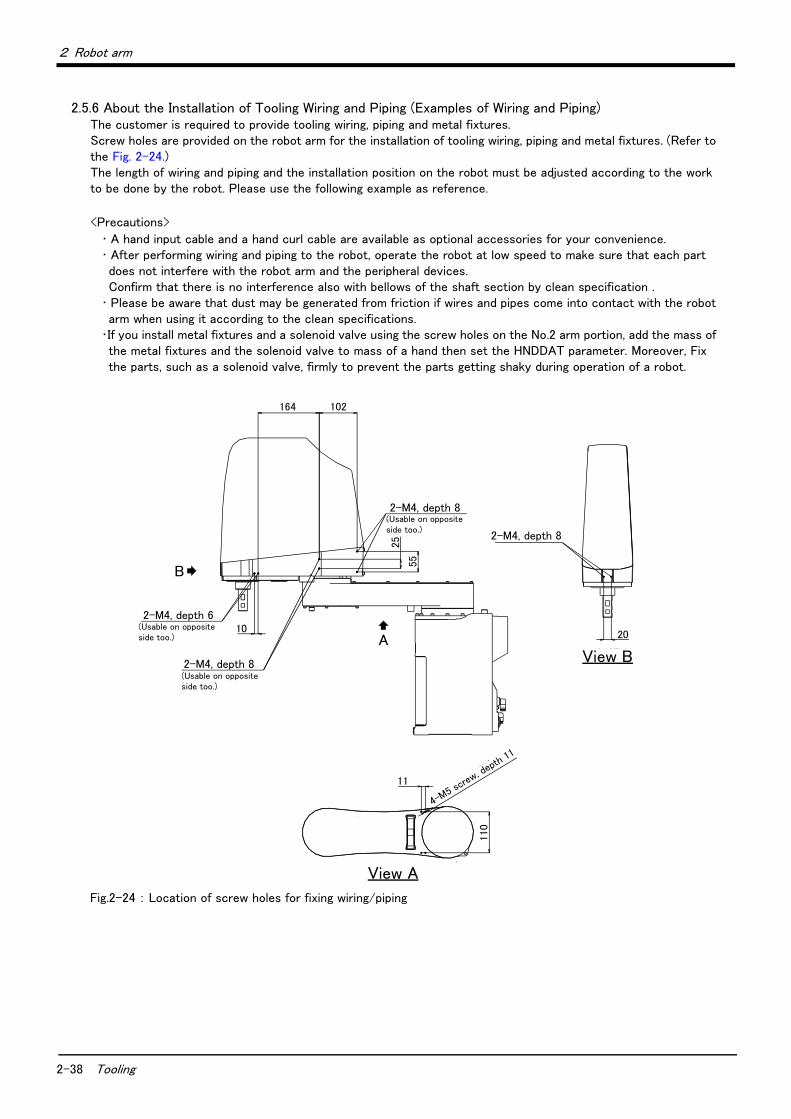
2-38 Tooling
2 Robot arm
2.5.6 About the Installation of Tooling Wiring and Piping (Examples of Wiring and Piping)The customer is required to provide tooling wiring, piping and metal fixtures. Screw holes are provided on the robot arm for the installation of tooling wiring, piping and metal fixtures. (Refer to the Fig. 2-24.)The length of wiring and piping and the installation position on the robot must be adjusted according to the work to be done by the robot. Please use the following example as reference.
<Precautions>
・ A hand input cable and a hand curl cable are available as optional accessories for your convenience.・ After performing wiring and piping to the robot, operate the robot at low speed to make sure that each part does not interfere with the robot arm and the peripheral devices.Confirm that there is no interference also with bellows of the shaft section by clean specification .
・ Please be aware that dust may be generated from friction if wires and pipes come into contact with the robot arm when using it according to the clean specifications.
・If you install metal fixtures and a solenoid valve using the screw holes on the No.2 arm portion, add the mass of the metal fixtures and the solenoid valve to mass of a hand then set the HNDDAT parameter. Moreover, Fix the parts, such as a solenoid valve, firmly to prevent the parts getting shaky during operation of a robot.
Fig.2-24 : Location of screw holes for fixing wiring/piping
164 102
2-M4深さ6(反対側にもあり) 10
2-M4深さ8(反対側にもあり)
2-M4深さ8(反対側にもあり)
25
55
2-M4深さ8
20
11
110
4-M5ね
じ深さ11
B
矢視BA
矢視A
(Usable on opposite side too.)
2-M4, depth 8
View B
View A
4-M5 s
crew, d
epth
11
2-M4, depth 8
(Usable on opposite side too.)
2-M4, depth 6
2-M4, depth 8(Usable on opposite side too.)

2 Robot arm
Tooling 2-39
(1) Example of wiring and piping <1>By feeding wiring and piping through the inside of the shaft, the wiring and piping to the hand becomes compact.
Fig.2-25 : Example of wiring and piping <1>
(2) Wiring and piping example <2>This is an effective method in cases where the wiring and piping is often changed, or when the hand rotation is minimal (within ±90°), etc.
Fig.2-26 : Example of wiring and piping <2>
2次配管エアホースなど ・ケーブル内装配線・配管セット(オプション) (ハンドチューブ:φ3×4本、ハンド入力ケーブル(信号用4本、電源用2本)) または ・ハンドチューブなど(お客様ご準備)
電磁弁セット(オプション)
1次配管エアホース(AIR OUT、RETURN)(第2アーム内)
ハンド出力信号コネクタ(GR1、GR2)(電磁弁オプション側)
ハンド出力信号コネクタ(GR1、GR2)(第2アーム内)
ケーブル内装配線・配管セット(オプション)用ケーブル固定板金
お客様ご準備ツール
Solenoid valve set (Option)
Cable fixed plate for Internal Wiring/Piping set for hand (Option)
Primary piping air hose (AIR OUT, RETURN)
Inside the No.2 arm
Hand output signal connector (GR1, GR2)
(Solenoid valve (option) side)
Hand output signal connector (GR1, GR2)
(Inside the No.2 arm)
Example of the customer preparation tool
Secondary piping air hose, etc・ Internal Wiring/Piping set for hand (Option)
(Hand tube: φ3 x 4 hoses, Hand input cable (For signal: 4 cable, For power: 2 cable))or
・ Hand tube (Customer prepared)
固定金具(お客様準備)
固定金具(お客様準備)
配線・配管(お客様準備)またはハンド入力ケーブル(オプション)
外部配線配管ボックス(オプション)
配線・配管(お客様準備)またはハンドカールチューブ(オプション)
お客様準備ツールExample of the customer preparation tool
Fixing plate (Customer preparation)Wiring/Piping (Customer preparation)orHand input cable (Option)
External Wiring/Piping box (Option)
Wiring/Piping (Customer preparation)orHand curl tube (Option)
Metal fittings (customer preparation)
2-40 Tooling
2 Robot arm
(3) Precautions for the clean specificationThe through hole of the top part of the tip shaft are taped at shipment.
Perform the following actions as necessary in order to ensure that the robot keeps sufficiently protective performance during the operation:
1) When the through hole of the shaft is not used・ Keep the top part of the tip shaft taped while the robot is in use.
2) When the through hole of the shaft is used for wiring.・ Remove the rubber cap on top of the tip shaft and perform the necessary wiring. Once the wiring is com-
pleted, seal the bottom part of the tip shaft using liquid seal in order to avoid accumulation of dust
・Perform the wiring in such a way that the wires around the area below the tip shaft will not get into contact with other parts while the robot is operating.
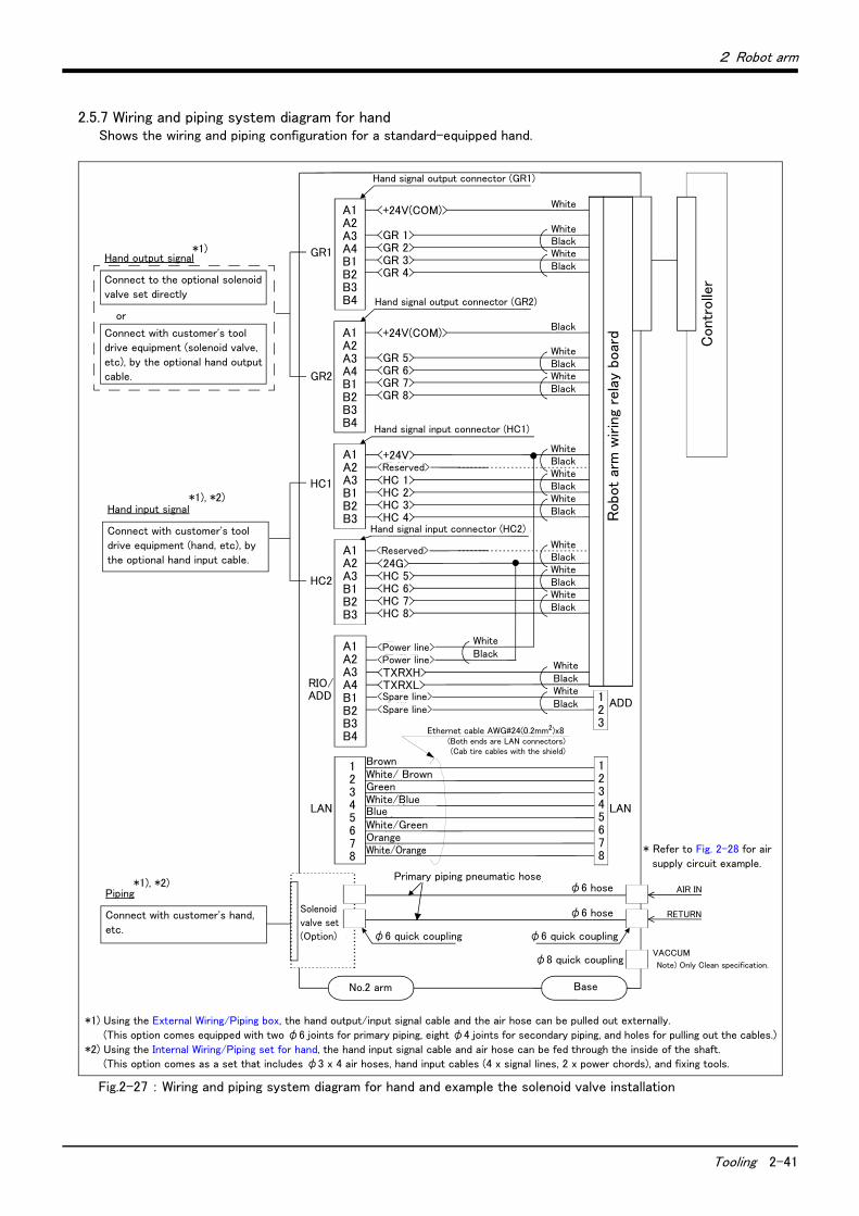
2 Robot arm
Tooling 2-41
2.5.7 Wiring and piping system diagram for handShows the wiring and piping configuration for a standard-equipped hand.
Fig.2-27 : Wiring and piping system diagram for hand and example the solenoid valve installation
白 A1A2A3A4B1B2B3B4
コントローラ
ロボット本体配線中継ボード
<+24V><予約><HC 1><HC 2><HC 3><HC 4>
A1A2A3B1B2B3
<+24V(COM)>
<GR 1><GR 2><GR 3><GR 4>
A1A2A3A4B1B2B3B4
<+24V(COM)>
<GR 5><GR 6><GR 7><GR 8>
ハンド信号出力用コネクタ(GR2コネクタ)
ハンド信号出力用コネクタ(GR1コネクタ)
ハンド信号入力用コネクタ(HC1コネクタ)
<予約><24G><HC 5><HC 6><HC 7><HC 8>
A1A2A3B1B2B3
ハンド信号入力用コネクタ(HC2コネクタ)
<電源用><電源用><TXRXH><TXRXL><予備><予備>
茶白茶緑白青青白緑橙白橙
φ6クイック継手
1次配管エアホース
φ6ホース
φ6ホース
φ6クイック継手
AIR IN
RETURN電磁弁セット(オプション)
第2アーム内 ベース部
φ8クイック継手
A1A2A3A4B1B2B3B4
白
黒
白
黒
黒
白
黒
白
黒
白
黒
白
黒
白
黒
白
黒
白
黒
白
黒
12345678
GR1
GR2
HC1
HC2
RIO/ADD
LAN
ADD
LAN
12345678
白
黒
白
黒
白
黒 123
* Refer to Fig. 2-28 for air
supply circuit example.
*1)
*1) Using the External Wiring/Piping box, the hand output/input signal cable and the air hose can be pulled out externally.
(This option comes equipped with two φ6 joints for primary piping, eight φ4 joints for secondary piping, and holes for pulling out the cables.)
*2) Using the Internal Wiring/Piping set for hand, the hand input signal cable and air hose can be fed through the inside of the shaft.
(This option comes as a set that includes φ3 x 4 air hoses, hand input cables (4 x signal lines, 2 x power chords), and fixing tools.
*1), *2)
Hand output signal
Connect to the optional solenoid
valve set directly
or
Connect with customer's tool
drive equipment (solenoid valve,
etc), by the optional hand output
cable.
Hand input signal
Connect with customer's tool
drive equipment (hand, etc), by
the optional hand input cable.
Piping
Connect with customer's hand,
etc.
*1), *2)
VACCUM
Note) Only Clean specification.
Hand signal output connector (GR1)
Hand signal output connector (GR2)
Hand signal input connector (HC1)
Hand signal input connector (HC2)
Solenoid
valve set
(Option)
No.2 arm Base
φ6 quick coupling φ6 quick coupling
φ8 quick coupling
Primary piping pneumatic hoseφ6 hose
φ6 hose
<Reserved>
<Reserved>
White
WhiteBlackWhiteBlack
Black
WhiteBlackWhiteBlack
WhiteBlackWhiteBlackWhiteBlack
WhiteBlackWhiteBlackWhiteBlack
Robo
t ar
m w
irin
g re
lay
boar
d
Contr
olle
r
<Power line><Power line>
Ethernet cable AWG#24(0.2mm2)x8(Both ends are LAN connectors)(Cab tire cables with the shield)
<Spare line><Spare line>
BlackWhite
BlackWhite
BlackWhite
BrownWhite/ BrownGreenWhite/BlueBlueWhite/GreenOrangeWhite/Orange
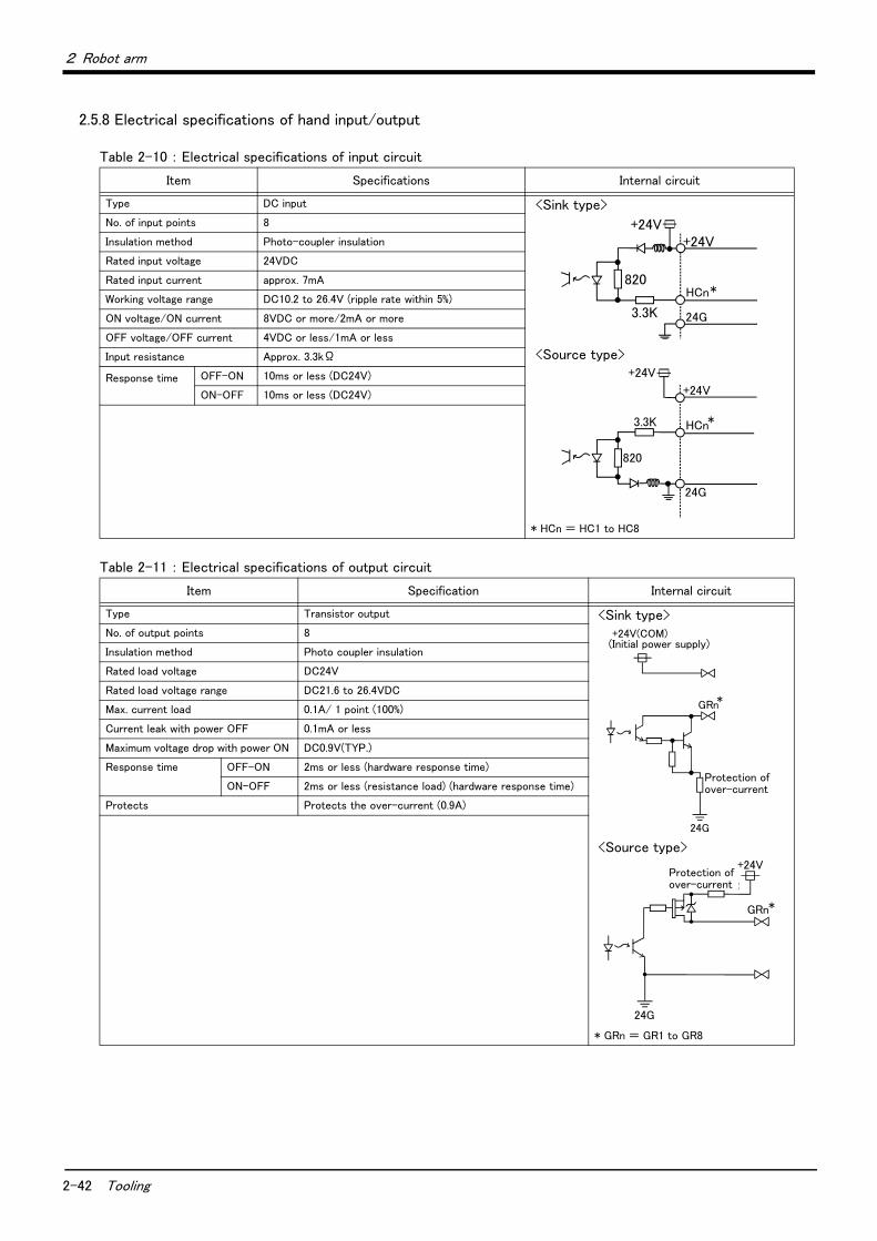
2-42 Tooling
2 Robot arm
2.5.8 Electrical specifications of hand input/output
Table 2-10 : Electrical specifications of input circuit
Table 2-11 : Electrical specifications of output circuit
Item Specifications Internal circuit
Type DC input <Sink type>
<Source type>
* HCn = HC1 to HC8
No. of input points 8
Insulation method Photo-coupler insulation
Rated input voltage 24VDC
Rated input current approx. 7mA
Working voltage range DC10.2 to 26.4V (ripple rate within 5%)
ON voltage/ON current 8VDC or more/2mA or more
OFF voltage/OFF current 4VDC or less/1mA or less
Input resistance Approx. 3.3kΩ
Response time
OFF-ON 10ms or less (DC24V)
ON-OFF 10ms or less (DC24V)
Item Specification Internal circuit
Type Transistor output <Sink type>
<Source type>
* GRn = GR1 to GR8
No. of output points 8
Insulation method Photo coupler insulation
Rated load voltage DC24V
Rated load voltage range DC21.6 to 26.4VDC
Max. current load 0.1A/ 1 point (100%)
Current leak with power OFF 0.1mA or less
Maximum voltage drop with power ON DC0.9V(TYP.)
Response time OFF-ON 2ms or less (hardware response time)
ON-OFF 2ms or less (resistance load) (hardware response time)
Protects Protects the over-current (0.9A)
3.3K
+24V
24G
820HCn*
+24V
3.3K
820
24G
+24V
HCn*
+24V
+24V(COM) (内部電源)
*GRn
過電流保護機能
24G
Protection of over-current
(Initial power supply)
* GRn
+24V
24G
過電流保護機能
Protection of over-current
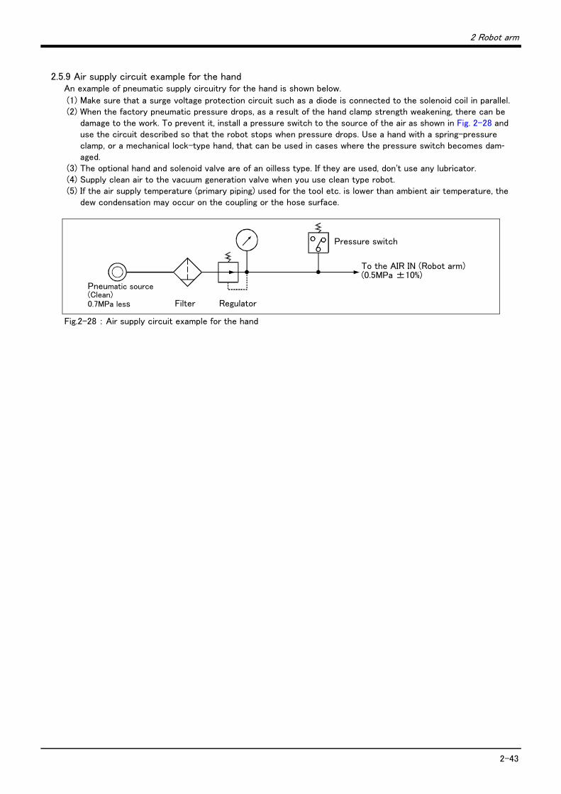
2 Robot arm
2-43
2.5.9 Air supply circuit example for the handAn example of pneumatic supply circuitry for the hand is shown below.
(1) Make sure that a surge voltage protection circuit such as a diode is connected to the solenoid coil in parallel.(2) When the factory pneumatic pressure drops, as a result of the hand clamp strength weakening, there can be
damage to the work. To prevent it, install a pressure switch to the source of the air as shown in Fig. 2-28 and use the circuit described so that the robot stops when pressure drops. Use a hand with a spring-pressure clamp, or a mechanical lock-type hand, that can be used in cases where the pressure switch becomes dam-aged.
(3) The optional hand and solenoid valve are of an oilless type. If they are used, don't use any lubricator.(4) Supply clean air to the vacuum generation valve when you use clean type robot.(5) If the air supply temperature (primary piping) used for the tool etc. is lower than ambient air temperature, the
dew condensation may occur on the coupling or the hose surface.
Fig.2-28 : Air supply circuit example for the hand
エア源(クリーンエアー)0.7MPa以下 フィルター レギュレーター
圧力スイッチ
ロボット本体のAIR INへ(0.5MPa±10%)
Pneumatic source(Clean)0.7MPa less Filter Regulator
Pressure switch
To the AIR IN (Robot arm)(0.5MPa ±10%)
2-44 Shipping special specifications, options, and maintenance parts
2 Robot arm
2.6 Shipping special specifications, options, and maintenance parts
2.6.1 Shipping special specifications
■ What are sipping special specifications?Shipping special specifications are changed before shipping from the factory. Consequently, it is necessary to confirm the delivery date by the customer.
To make changes to the specifications after shipment, service work must be performed at the work site or the robot must be returned for service.
■ How to order(1) Confirm beforehand when the factory special specifications can be shipped, because they may not be
immediately available.(2) Specify, before shipping from our company.(3) Specified method …… Specify the part name, model, and robot model type.
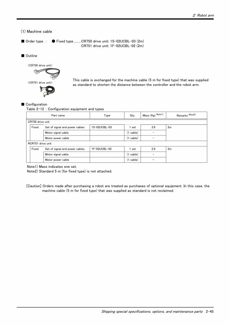
2 Robot arm
Shipping special specifications, options, and maintenance parts 2-45
(1) Machine cable
■ Order type : ● Fixed type .........CR750 drive unit: 1S-02UCBL-03 (2m)CR751 drive unit: 1F-02UCBL-02 (2m)
■ Outline
This cable is exchanged for the machine cable (5 m for fixed type) that was supplied as standard to shorten the distance between the controller and the robot arm.
■ ConfigurationTable 2-12 : Configuration equipment and types
[Caution] Orders made after purchasing a robot are treated as purchases of optional equipment. In this case, themachine cable (5 m for fixed type) that was supplied as standard is not reclaimed.
Part name Type Qty. Mass (Kg) Note1)
Note1) Mass indicates one set.
Remarks Note2)
Note2) Standard 5 m (for fixed type) is not attached.
CR750 drive unit
Fixed Set of signal and power cables 1S-02UCBL-03 1 set 2.6 2m
Motor signal cable (1 cable) -
Motor power cable (1 cable) -
RCR751 drive unit
Fixed Set of signal and power cables 1F-02UCBL-02 1 set 2.6 2m
Motor signal cable (1 cable) -
Motor power cable (1 cable) -
<CR750 drive unit>
<CR751 drive unit>
2-46 Options
2 Robot arm
2.7 Options
■ What are options?There are a variety of options for the robot designed to make the setting up process easier for customer needs.
customer installation is required for the options. Options come in two types: "set options" and "single options".
1. Set options .......................................A combination of single options and parts that together, from a set for servingsome purpose.
2. Single options ..................................That are configured from the fewest number of required units of a part.Please choose customer's purpose additionally.

2 Robot arm
Options 2-47
(1) Machine cable extension
■ Order type: ● CR750 drive unit..........Fixed type: 1S- □□ CBL-03 (extension type)Flexed type: 1S- □□ LCBL-03 (extension type)
Flexed type: 1S- □□ LUCBL-03 (direct type)
● CR751 drive unit..........Fixed type: 1F- □□ UCBL-02 (direct type)
Flexed type: 1F- □□ LUCBL-02 (direct type)
Note) □□ refer the length.
■ Outline
The distance between the robot controller and the robot arm is extensible by this option.
A fixed type and flexible type are available.
The fix and flexible types are both configured of the motor signal cable and motor power cable.
The extended method is discriminated as follows.
Direct type ............・ Exchanges with the machine cable attached in the standards.
Extension type.....・ Adds to the machine cable attached in the standards.
■ ConfigurationTable 2-13 : Configuration equipment and types
Part name Type Note1)
Note1) The numbers in the boxes □□ refer the length.
Qty. Mass (kg) Note2)
Note2) Mass indicates one set.
RemarksFixed Flexed
CR750 controller
Fixed Set of signal and power cables 1S- □□ CBL-03 1 set - 4.3(5m)
7.6(10m)
11(15m)
5m, 10m or 15m each
Extension typeMotor signal cable (1 cable) -
Motor power cable (1 cable) -
Flexed Set of signal and power cables 1S- □□ LCBL-03 - 1 set 6.2(5m)
11(10m)
15.4(15m)
5m, 10m or 15m each
Extension typeMotor signal cable - (1 cable)
Motor power cable - (1 cable)
Flexed Set of signal and power cables 1S- □□ LUCBL-03 - 1 set 6.2(5m)
11(10m)
15.4(15m)
5m, 10m or 15m each
Direct typeMotor signal cable - (1 cable)
Motor power cable - (1 cable)
Nylon clamp NK-14N - 2 pcs. - for motor signal cable
Nylon clamp NK-18N - 2 pcs. - for motor power cable
Silicon rubber - 4 pcs -
CR751 controller
Fixed Set of signal and power cables 1F- □□ UCBL-02 1 set - 6.7(10m)
12(15m)
17(20m)
10m, 15m or 20m each
Direct typeMotor signal cable (1 cable) -
Motor power cable (1 cable) -
Flexed Set of signal and power cables 1F- □□ LUCBL-02 - 1 set 7(10m)
13(15m)
17(20m)
10m, 15m or 20m each
Direct typeMotor signal cable - (1 cable)
Motor power cable - (1 cable)
Nylon clamp NK-14N - 2 pcs. - for motor signal cable
Nylon clamp NK-18N - 2 pcs. - for motor power cable
Silicon rubber - 4 pcs -
<CR750drive unit>
<CR751drive unit>
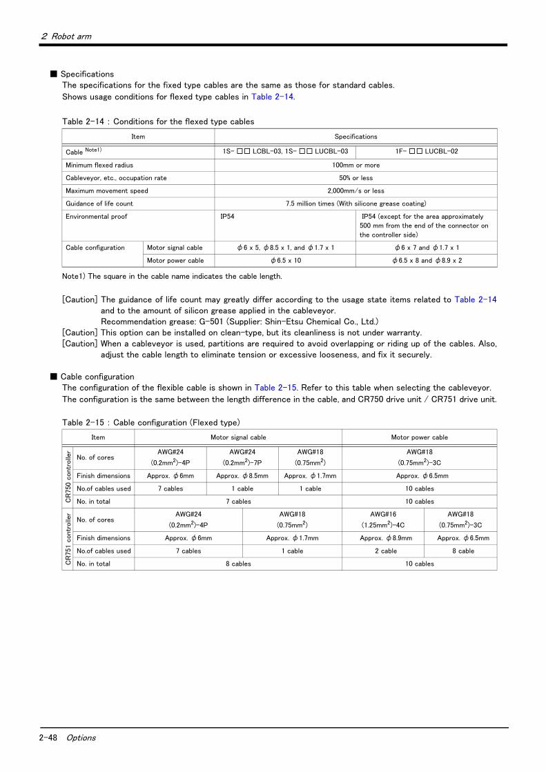
2-48 Options
2 Robot arm
■ SpecificationsThe specifications for the fixed type cables are the same as those for standard cables.
Shows usage conditions for flexed type cables in Table 2-14.
Table 2-14 : Conditions for the flexed type cables
[Caution] The guidance of life count may greatly differ according to the usage state items related to Table 2-14and to the amount of silicon grease applied in the cableveyor.Recommendation grease: G-501 (Supplier: Shin-Etsu Chemical Co., Ltd.)
[Caution] This option can be installed on clean-type, but its cleanliness is not under warranty.[Caution] When a cableveyor is used, partitions are required to avoid overlapping or riding up of the cables. Also,
adjust the cable length to eliminate tension or excessive looseness, and fix it securely.
■ Cable configurationThe configuration of the flexible cable is shown in Table 2-15. Refer to this table when selecting the cableveyor.
The configuration is the same between the length difference in the cable, and CR750 drive unit / CR751 drive unit.
Table 2-15 : Cable configuration (Flexed type)
Item Specifications
Cable Note1)
Note1) The square in the cable name indicates the cable length.
1S- □□ LCBL-03, 1S- □□ LUCBL-03 1F- □□ LUCBL-02
Minimum flexed radius 100mm or more
Cableveyor, etc., occupation rate 50% or less
Maximum movement speed 2,000mm/s or less
Guidance of life count 7.5 million times (With silicone grease coating)
Environmental proof IP54 IP54 (except for the area approximately
500 mm from the end of the connector on
the controller side)
Cable configuration Motor signal cable φ6 x 5, φ8.5 x 1, and φ1.7 x 1 φ6 x 7 and φ1.7 x 1
Motor power cable φ6.5 x 10 φ6.5 x 8 and φ8.9 x 2
Item Motor signal cable Motor power cable
CR
750
contr
olle
r
No. of coresAWG#24
(0.2mm2)-4P
AWG#24
(0.2mm2)-7P
AWG#18
(0.75mm2)
AWG#18
(0.75mm2)-3C
Finish dimensions Approx. φ6mm Approx. φ8.5mm Approx. φ1.7mm Approx. φ6.5mm
No.of cables used 7 cables 1 cable 1 cable 10 cables
No. in total 7 cables 10 cables
CR
751
contr
olle
r
No. of coresAWG#24
(0.2mm2)-4P
AWG#18
(0.75mm2)
AWG#16
(1.25mm2)-4C
AWG#18
(0.75mm2)-3C
Finish dimensions Approx. φ6mm Approx. φ1.7mm Approx. φ8.9mm Approx. φ6.5mm
No.of cables used 7 cables 1 cable 2 cable 8 cable
No. in total 8 cables 10 cables
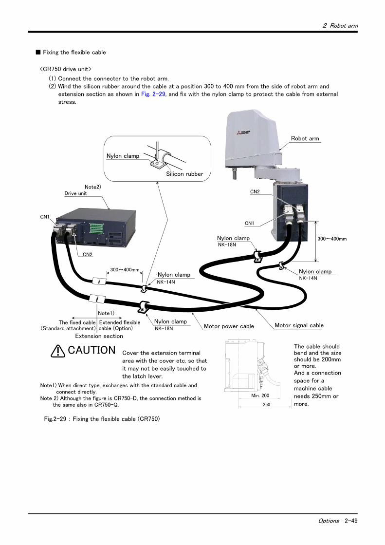
2 Robot arm
Options 2-49
■ Fixing the flexible cable
Fig.2-29 : Fixing the flexible cable (CR750)
シリコンゴム
ナイロンクランプ
モータ電源ケーブル モータ信号ケーブル
ロボット本体
コントローラ
CN1
CN2
CN1
CN2
標準付属5m固定ケーブル
延長屈曲ケーブル(オプション)
継足し部分
ナイロンクランプ NK-14N
ナイロンクランプ NK-18N
ナイロンクランプ NK-18N
NK-14Nナイロンクランプ 300~400mm
300~400mm
The cable should bend and the size should be 200mm or more.And a connection space for a machine cable needs 250mm or more.
Note1) When direct type, exchanges with the standard cable and connect directly.
Note 2) Although the figure is CR750-D, the connection method is the same also in CR750-Q.
Drive unitNote2)
Nylon clamp
Silicon rubber
Robot arm
Cover the extension terminal area with the cover etc. so that it may not be easily touched to the latch lever.
CAUTION
Nylon clamp
Nylon clamp
Nylon clamp
Nylon clamp
Extended flexible cable (Option)
The fixed cable(Standard attachment) Motor power cable Motor signal cable
Note1)
<CR750 drive unit>
(1) Connect the connector to the robot arm.(2) Wind the silicon rubber around the cable at a position 300 to 400 mm from the side of robot arm and
extension section as shown in Fig. 2-29, and fix with the nylon clamp to protect the cable from external stress.
最小200
250
Min. 200
Extension section

2-50 Options
2 Robot arm
Fig.2-30 : Fixing the flexible cable (CR751)
シリコンゴム
ナイロンクランプ
モータ電源ケーブル
モータ信号ケーブル
ロボット本体
CN2
ナイロンクランプ NK-14N
NK-18N
ナイロンクランプ NK-18N
NK-14Nナイロンクランプ
300~500mm
300~ 500mm
ナイロンクランプ
AMP1・AMP2
BRK
コントローラ
CN2
CN1
モータ信号(CN2)モータ電源(CN1)
AMP1 AMP2 BRK
コントローラコネクタ面
ネジ(固定用 2本)
ネジ(固定用 2本)
熱収縮チューブ
熱収縮チューブ
*1) Connect the robot arm side connector to the connector which is inside the CONBOX cover.
*2) The flexible cable area is the area between the heat shrink tubes on the robot and the controller sides.
*3) Although the figure is CR750-D, the connection method is the same also in CR750-Q.
*1)
Drive unit*3)
Nylon clamp
Silicon rubber
Robot arm
Nylon clamp Motor signal cable
Motor power cable
Nylon clamp
Nylon clamp
<CR751 drive unit>
Two fixing screws
Two fixing screws
Drive unit connector face
Motor power (CN1) Motor signal (CN2)
Nylon clamp
(1) Connect the connector to the robot arm.(2) For protection of wires from external stress, refer to Fig. 2-30. Wrap the cable with the supplied silicon
rubber and fix the cable with nylon clamps in the area between the heat shrink tubes on the robot and the controller sides (flexible cable area).
Heat shrink tube*2)
Heat shrink tube*2)
最小200
250The cable should bend and the size should be 200mm or more.And a connection space for a machine cable needs 250mm or more.
Min. 200
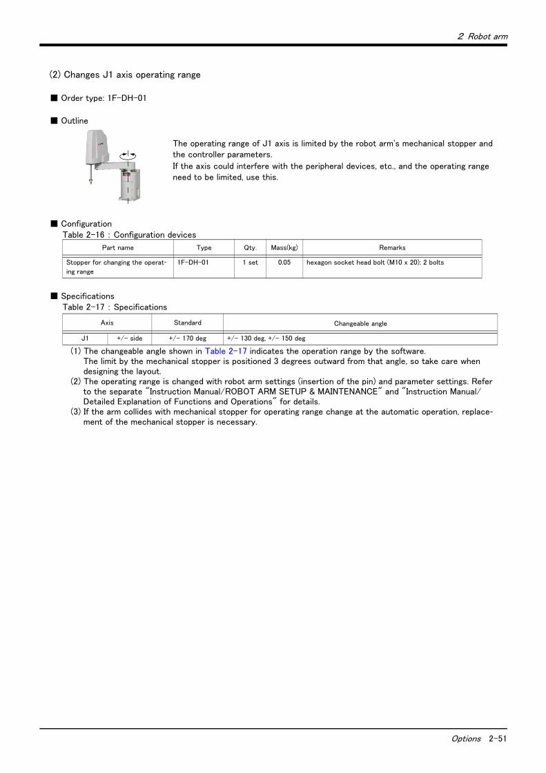
2 Robot arm
Options 2-51
(2) Changes J1 axis operating range
■ Order type: 1F-DH-01
■ Outline
The operating range of J1 axis is limited by the robot arm's mechanical stopper and the controller parameters.
If the axis could interfere with the peripheral devices, etc., and the operating range need to be limited, use this.
■ ConfigurationTable 2-16 : Configuration devices
■ SpecificationsTable 2-17 : Specifications
(1) The changeable angle shown in Table 2-17 indicates the operation range by the software.The limit by the mechanical stopper is positioned 3 degrees outward from that angle, so take care when designing the layout.
(2) The operating range is changed with robot arm settings (insertion of the pin) and parameter settings. Refer to the separate "Instruction Manual/ROBOT ARM SETUP & MAINTENANCE" and "Instruction Manual/Detailed Explanation of Functions and Operations" for details.
(3) If the arm collides with mechanical stopper for operating range change at the automatic operation, replace-ment of the mechanical stopper is necessary.
Part name Type Qty. Mass(kg) Remarks
Stopper for changing the operat-ing range
1F-DH-01 1 set 0.05 hexagon socket head bolt (M10 x 20): 2 bolts
Axis Standard Changeable angle
J1 +/- side +/- 170 deg +/- 130 deg, +/- 150 deg
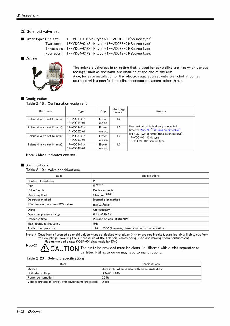
2-52 Options
2 Robot arm
(3) Solenoid valve set
■ Order type: One set: 1F-VD01-01(Sink type)/1F-VD01E-01(Source type)Two sets: 1F-VD02-01(Sink type)/1F-VD02E-01(Source type)
Three sets: 1F-VD03-01(Sink type)/1F-VD03E-01(Source type)
Four sets: 1F-VD04-01(Sink type)/1F-VD04E-01(Source type)
■ Outline
The solenoid valve set is an option that is used for controlling toolings when various toolings, such as the hand, are installed at the end of the arm.Also, for easy installation of this electromaagnetic set onto the robot, it comes equipped with a manifold, couplings, connectors, among other things.
■ ConfigurationTable 2-18 : Configuration equipment
■ SpecificationsTable 2-19 : Valve specifications
Table 2-20 : Solenoid specifications
Part name Type Q'tyMass (kg)
Note1)
Note1) Mass indicates one set.
Remark
Solenoid valve set (1 sets) 1F-VD01-01/
1F-VD01E-01
Either
one pc.
1.0
Hand output cable is already connected.
Refer to Page 55, "(5) Hand output cable".
M4 x 30 Two screws (Installation screws)
1F-VD0*-01: Sink type1F-VD0*E-01: Source type.
Solenoid valve set (2 sets) 1F-VD02-01/
1F-VD02E-01
Either
one pc.
1.0
Solenoid valve set (3 sets) 1F-VD03-01/
1F-VD03E-01
Either
one pc.
1.0
Solenoid valve set (4 sets) 1F-VD04-01/
1F-VD04E-01
Either
one pc.
1.0
Item Specifications
Number of positions 2
Port 5 Note1)
Note1) Couplings of unused solenoid valves must be blocked with plugs. If they are not blocked, supplied air will blow out from the couplings, lowering the air pressure of the solenoid valves being used and making them nonfunctional.
Recommended plugs: KQ2P-04 plug made by SMC
Valve function Double solenoid
Operating fluid Clean air Note2)
Note2)
Operating method Internal pilot method
Effective sectional area (CV value) 0.64mm2(0.03)
Oiling Unnecessary
Operating pressure range 0.1 to 0.7MPa
Response time 22msec or less (at 0.5 MPa)
Max. operating frequency 5Hz
Ambient temperature -10 to 50 ℃ (However, there must be no condensation.)
Item Specifications
Method Built-in fly-wheel diodes with surge protection
Coil rated voltage DC24V ±10%
Power consumption 0.55W
Voltage protection circuit with power surge protection Diode
CAUTION The air to be provided must be clean, i.e., filtered with a mist separator or air filter. Failing to do so may lead to malfunctions.
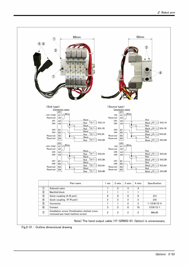
2 Robot arm
Options 2-53
Fig.2-31 : Outline dimensional drawing
SOL1A
SOL1B
SOL2A
SOL2B
A3
<GR1>
A4
A1A2
B3B4
B1B2
SOL3A
SOL3B
SOL4A
SOL4B
A3
<GR2>
A4
A1A2
B3B4
B1B2
<ソースタイプ><シンクタイプ>コネクタ名
SOL1A
SOL1B
SOL2A
SOL2B
A3
<GR1>
A4
A1A2
B3B4
B1B2
SOL3A
SOL3B
SOL4A
SOL4B
A3
<GR2>
A4
A1A2
B3B4
B1B2
コネクタ名
GR1
GR2
+24V (COM)
予約
予約
予約
GR3
GR4
GR5
GR6
+24V (COM)
予約
予約
予約
GR7
GR8
GR1
GR2
24G
予約
予約
予約
GR3
GR4
GR5
GR6
24G
予約
予約
予約
GR7
GR8
クロ
アカ
クロ
アカ
クロ
アカ
クロ
アカ
白
クロ
アカ
クロ
アカ
クロ
アカ
クロ
アカ
白
クロ
アカ
クロ
アカ
クロ
アカ
クロ
アカ
白
クロ
アカ
クロ
アカ
クロ
アカ
クロ
アカ
白
50mm80mm①
②③
④
⑤ ⑥
⑦
Part name 1 set 2 sets 3 sets 4 sets Specification
① Solenoid valve 1 2 3 4
② Manifold block 1 1 1 1
③ Quick coupling (A/B port) 8 8 8 8 φ4
④ Quick coupling (P/R port) 2 2 2 2 φ6
⑤ Connector 1 1 2 2 1-1318115-4
⑥ Contact 3 5 8 10 1318112-1
⑦Installation screw (Combination slotted-cross recessed pan head machine screw)
2 2 2 2 M4x30
Note) The hand output cable (1F-GR60S-01: Option) is unnecessary.
<Sink type>Connector name
Reserved
ReservedReserved
Reserved
ReservedReserved
White
White
Black
RedBlack
RedBlack
RedBlack
Red
Black
RedBlack
RedBlack
RedBlack
Red
<Source type>Connector name
Reserved
ReservedReserved
Reserved
ReservedReserved
White
White
Red
Black
Red
BlackRed
Black
Red
Black
Red
Black
Red
Black
Red
Black
Red
Black
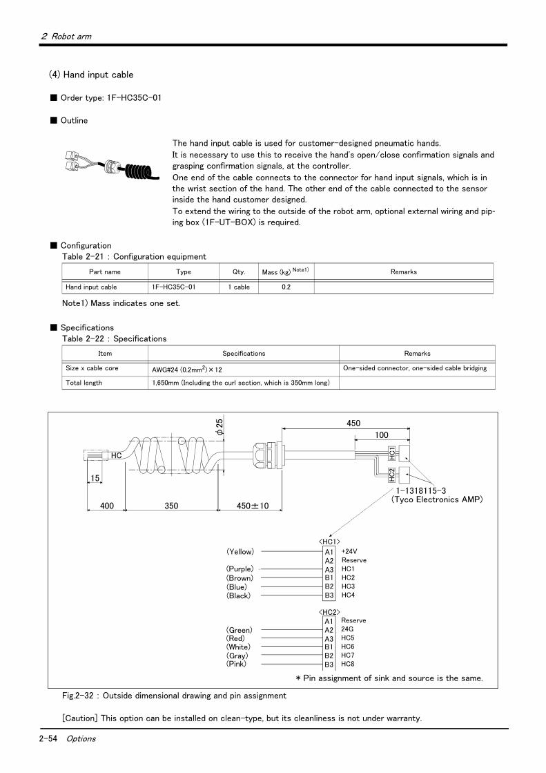
2-54 Options
2 Robot arm
(4) Hand input cable
■ Order type: 1F-HC35C-01
■ Outline
The hand input cable is used for customer-designed pneumatic hands.
It is necessary to use this to receive the hand's open/close confirmation signals and grasping confirmation signals, at the controller.
One end of the cable connects to the connector for hand input signals, which is in the wrist section of the hand. The other end of the cable connected to the sensor inside the hand customer designed.
To extend the wiring to the outside of the robot arm, optional external wiring and pip-ing box (1F-UT-BOX) is required.
■ ConfigurationTable 2-21 : Configuration equipment
■ SpecificationsTable 2-22 : Specifications
Fig.2-32 : Outside dimensional drawing and pin assignment
[Caution] This option can be installed on clean-type, but its cleanliness is not under warranty.
Part name Type Qty. Mass (kg) Note1)
Note1) Mass indicates one set.
Remarks
Hand input cable 1F-HC35C-01 1 cable 0.2
Item Specifications Remarks
Size x cable core AWG#24 (0.2mm2)×12 One-sided connector, one-sided cable bridging
Total length 1,650mm (Including the curl section, which is 350mm long)
15
400 350 450±10
450
φ25
1-1318115-3(タイコエレクトロニクスアン
HC HC
1H
C2
HC1 HC2 HC3 HC4
+24V 予約
24GHC5 HC6
(ハンド 入力1)
(ハンド 入力2)
(ハンド 入力3)
(ハンド 入力4)
(ハンド 入力5)
(ハンド 入力6)
A1(黄)キ
(紫)ムラサキ(茶)チャ
(青)アオ(黒)クロ
(緑)ミドリ(赤)アカ(白)シロ
A2A3B1B2B3
A1A2A3B1B2B3
予約
HC7 HC8
(ハンド 入力7)
(ハンド 入力8) (灰)ハイ(桃)モモ
<HC1>
<HC2>
100
* Pin assignment of sink and source is the same.
(Tyco Electronics AMP)
(Purple)(Brown)(Blue)(Black)
(Yellow)
(Green)(Red)(White)(Gray)(Pink)
+24VReserveHC1HC2HC3HC4
Reserve24GHC5HC6HC7HC8
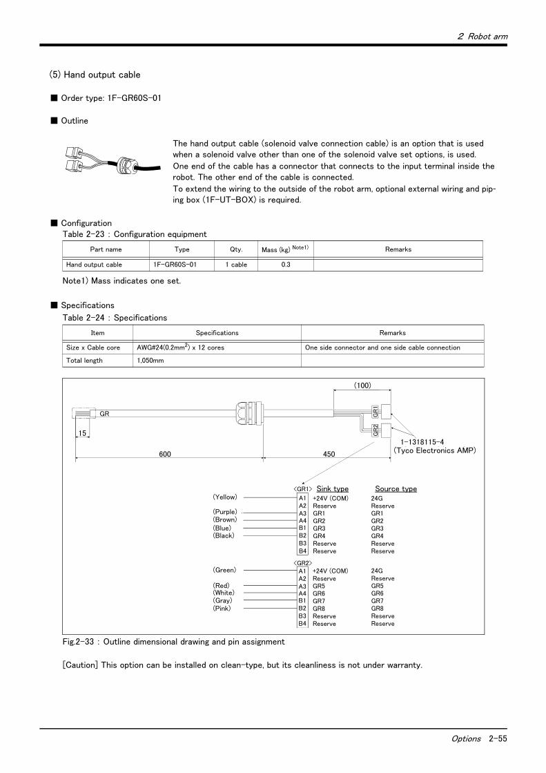
2 Robot arm
Options 2-55
(5) Hand output cable
■ Order type: 1F-GR60S-01
■ Outline
The hand output cable (solenoid valve connection cable) is an option that is used when a solenoid valve other than one of the solenoid valve set options, is used.
One end of the cable has a connector that connects to the input terminal inside the robot. The other end of the cable is connected.
To extend the wiring to the outside of the robot arm, optional external wiring and pip-ing box (1F-UT-BOX) is required.
■ ConfigurationTable 2-23 : Configuration equipment
■ Specifications
Table 2-24 : Specifications
Fig.2-33 : Outline dimensional drawing and pin assignment
[Caution] This option can be installed on clean-type, but its cleanliness is not under warranty.
Part name Type Qty. Mass (kg) Note1)
Note1) Mass indicates one set.
Remarks
Hand output cable 1F-GR60S-01 1 cable 0.3
Item Specifications Remarks
Size x Cable core AWG#24(0.2mm2) x 12 cores One side connector and one side cable connection
Total length 1,050mm
15
600
(100)
1-1318115-4(タイコエレクトロニクスアンプ(株))
GR
1G
R2
GR
GR1
GR3 GR4 予約
+24V (COM)予約
+24V(COM)
GR5
GR7
(ハンド 出力1)
(ハンド 出力3)
(ハンド 出力4)
(ハンド 出力5)
(ハンド 出力7)
A1(黄)キ
(紫)ムラサキ(茶)チャ
(青)アオ(黒)クロ
(緑)ミドリ
(赤)アカ(白)シロ
A2A3
B1B2B3
A1A2A3
B1B2B3
予約
GR8 予約
(ハンド 出力8) (灰)ハイ(桃)モモ
<GR1>
<GR2>
予約 B4
GR2 ハンド 出力2) A4
GR6 (ハンド 出力6) A4
B4 予約
シンクタイプ
GR1
GR3 GR4 予約
24GND (COM)予約
24GND(COM)
GR5
GR7
(ハンド 出力1)
(ハンド 出力3)
(ハンド 出力4)
(ハンド 出力5)
(ハンド 出力7)
予約
GR8 予約
(ハンド 出力8)
予約
GR2 ハンド 出力2)
GR6 (ハンド 出力6)
予約
ソースタイプ
450 (Tyco Electronics AMP)
(Yellow) +24V (COM)ReserveGR1GR2GR3GR4ReserveReserve
(Purple)(Brown)(Blue)(Black)
(Green)
(Red)(White)(Gray)(Pink)
+24V (COM)ReserveGR5GR6GR7GR8ReserveReserve
24GReserveGR1GR2GR3GR4ReserveReserve
24GReserveGR5GR6GR7GR8ReserveReserve
Sink type Source type
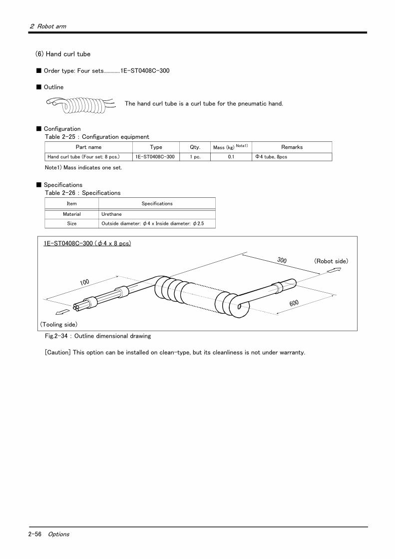
2-56 Options
2 Robot arm
(6) Hand curl tube
■ Order type: Four sets............1E-ST0408C-300
■ Outline
The hand curl tube is a curl tube for the pneumatic hand.
■ ConfigurationTable 2-25 : Configuration equipment
■ SpecificationsTable 2-26 : Specifications
Fig.2-34 : Outline dimensional drawing
[Caution] This option can be installed on clean-type, but its cleanliness is not under warranty.
Part name Type Qty. Mass (kg) Note1)
Note1) Mass indicates one set.
Remarks
Hand curl tube (Four set: 8 pcs.) 1E-ST0408C-300 1 pc. 0.1 Φ4 tube, 8pcs
Item Specifications
Material Urethane
Size Outside diameter: φ4 x Inside diameter: φ2.5
100
(ツーリング側)
300
600
(ロボット側)
1E-ST0408C-300 (φ4 x 8 pcs)
(Tooling side)
(Robot side)
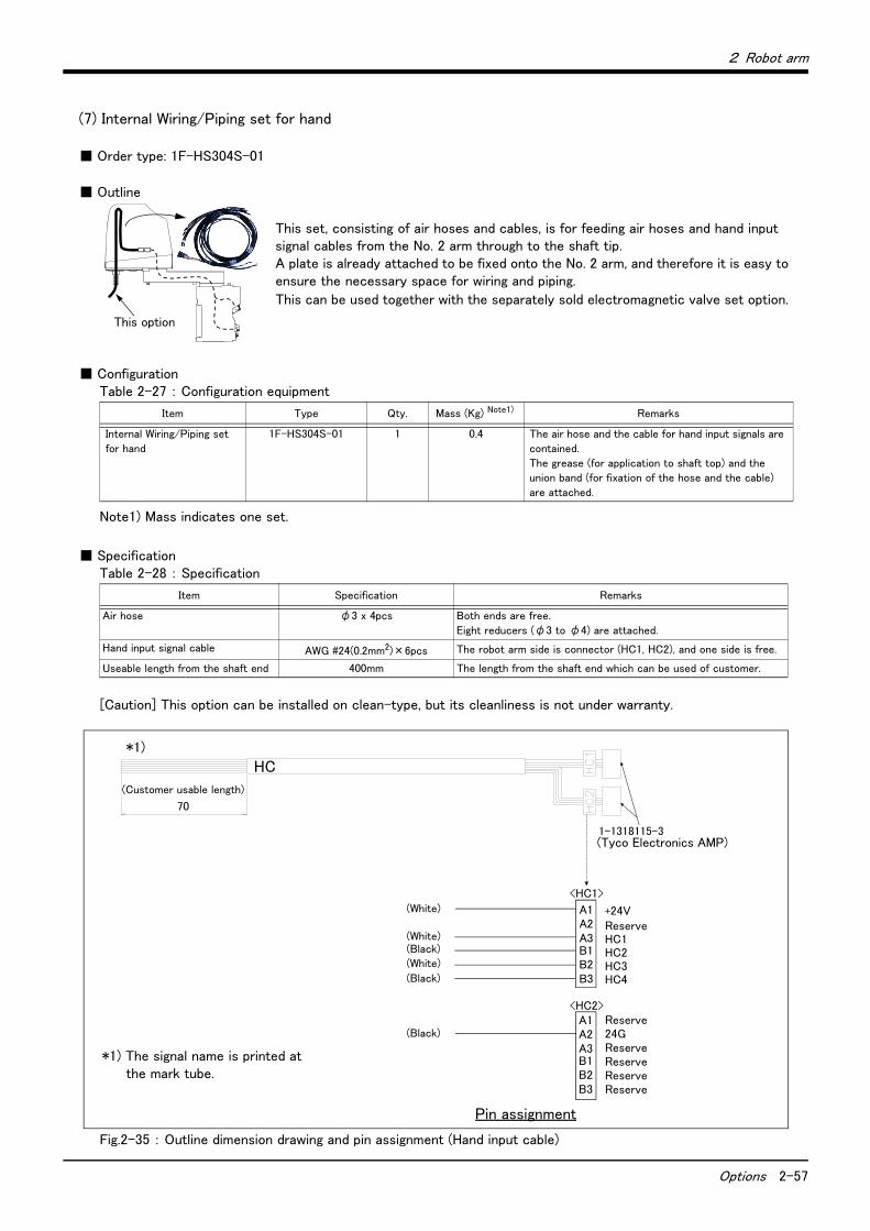
2 Robot arm
Options 2-57
(7) Internal Wiring/Piping set for hand
■ Order type: 1F-HS304S-01
■ Outline
This set, consisting of air hoses and cables, is for feeding air hoses and hand input signal cables from the No. 2 arm through to the shaft tip. A plate is already attached to be fixed onto the No. 2 arm, and therefore it is easy to ensure the necessary space for wiring and piping.
This can be used together with the separately sold electromagnetic valve set option.
■ ConfigurationTable 2-27 : Configuration equipment
■ SpecificationTable 2-28 : Specification
[Caution] This option can be installed on clean-type, but its cleanliness is not under warranty.
Fig.2-35 : Outline dimension drawing and pin assignment (Hand input cable)
Item Type Qty. Mass (Kg) Note1)
Note1) Mass indicates one set.
Remarks
Internal Wiring/Piping set
for hand
1F-HS304S-01 1 0.4 The air hose and the cable for hand input signals are
contained.
The grease (for application to shaft top) and the
union band (for fixation of the hose and the cable)
are attached.
Item Specification Remarks
Air hose φ3 x 4pcs Both ends are free.
Eight reducers (φ3 to φ4) are attached.
Hand input signal cable AWG #24(0.2mm2)×6pcs The robot arm side is connector (HC1, HC2), and one side is free.
Useable length from the shaft end 400mm The length from the shaft end which can be used of customer.
This option
HC1 HC2 HC3 HC4
+24V 予約
24G
(ハンド入力)
(ハンド入力)
(ハンド入力)
(ハンド入力)
A1(白)シロ
A2A3B1B2B3
A1A2A3B1B2B3
予約
<HC1>
<HC2>
予約予約予約予約
配線図
(白)シロ(黒)クロ(白)シロ(黒)クロ
(黒)クロ
1-1318115-3(タイコエレクトロニクスアンプ(株))
(お客様ご使用可能長)70
HC*1)
*1) The signal name is printed at the mark tube.
(Customer usable length)
(Tyco Electronics AMP)
+24VReserveHC1HC2HC3HC4
(White)
(White)(Black)(White)
(Black)
(Black)
Pin assignment
Reserve24GReserveReserveReserveReserve
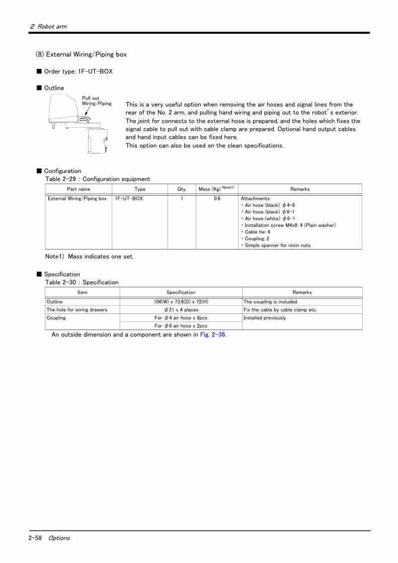
2-58 Options
2 Robot arm
(8) External Wiring/Piping box
■ Order type: 1F-UT-BOX
■ Outline
This is a very useful option when removing the air hoses and signal lines from the rear of the No. 2 arm, and pulling hand wiring and piping out to the robot’s exterior.
The joint for connects to the external hose is prepared, and the holes which fixes the signal cable to pull out with cable clamp are prepared. Optional hand output cables and hand input cables can be fixed here.
This option can also be used on the clean specifications.
■ ConfigurationTable 2-29 : Configuration equipment
■ SpecificationTable 2-30 : Specification
An outside dimension and a component are shown in Fig. 2-36.
Part name Type Qty. Mass (Kg) Note1)
Note1) Mass indicates one set.
Remarks
External Wiring/Piping box 1F-UT-BOX 1 0.6 Attachments:
・ Air hose (black) φ4-8
・ Air hose (black) φ6-1
・ Air hose (white) φ6-1
・ Installation screw M4x8: 4 (Plain washer)
・ Cable tie: 4
・ Coupling: 2
・ Simple spanner for resin nuts
Item Specification Remarks
Outline 106(W) x 73.6(D) x 72(H) The coupling is included.
The hole for wiring drawers φ21 x 4 places Fix the cable by cable clamp etc.
Coupling For φ4 air hose x 8pcs Installed previously
For φ6 air hose x 2pcs
Pull out Wiring/Piping
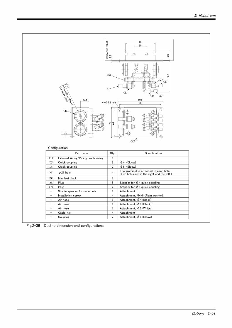
2 Robot arm
Options 2-59
Fig.2-36 : Outline dimension and configurations
Configuration
Part name Qty. Specification
<1> External Wiring/Piping box housing 1
<2> Quick coupling 8 φ4 (Elbow)
<3> Quick coupling 2 φ6 (Elbow)
<4> φ21 hole 4 The grommet is attached to each hole. (Two holes are in the right and the left.)
<5> Manifold block 1
<6> Plug 8 Stopper for φ4 quick coupling
<7> Plug 2 Stopper for φ6 quick coupling
- Simple spanner for resin nuts 1 Attachment
- Installation screw 4 Attachment, M4x8 (Plain washer)
- Air hose 8 Attachment, φ4 (Black)
- Air hose 1 Attachment, φ6 (Black)
- Air hose 1 Attachment, φ6 (White)
- Cable tie 4 Attachment
- Coupling 2 Attachment, φ6 (Elbow)
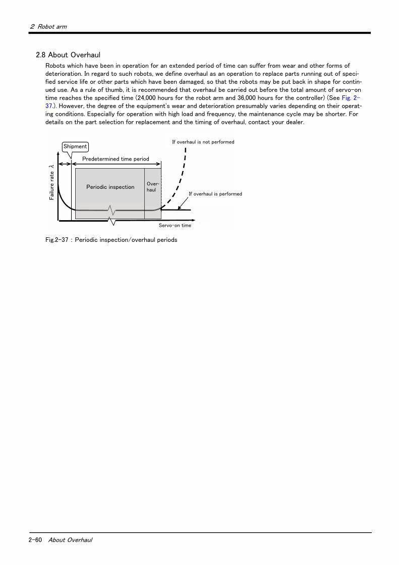
2-60 About Overhaul
2 Robot arm
2.8 About Overhaul
Robots which have been in operation for an extended period of time can suffer from wear and other forms of deterioration. In regard to such robots, we define overhaul as an operation to replace parts running out of speci-fied service life or other parts which have been damaged, so that the robots may be put back in shape for contin-ued use. As a rule of thumb, it is recommended that overhaul be carried out before the total amount of servo-on time reaches the specified time (24,000 hours for the robot arm and 36,000 hours for the controller) (See Fig. 2-37.). However, the degree of the equipment's wear and deterioration presumably varies depending on their operat-ing conditions. Especially for operation with high load and frequency, the maintenance cycle may be shorter. For details on the part selection for replacement and the timing of overhaul, contact your dealer.
Fig.2-37 : Periodic inspection/overhaul periods
Shipment
Fai
lure
rat
e λ
Predetermined time period
If overhaul is performed
Servo-on time
If overhaul is not performed
Periodic inspectionOver-haul
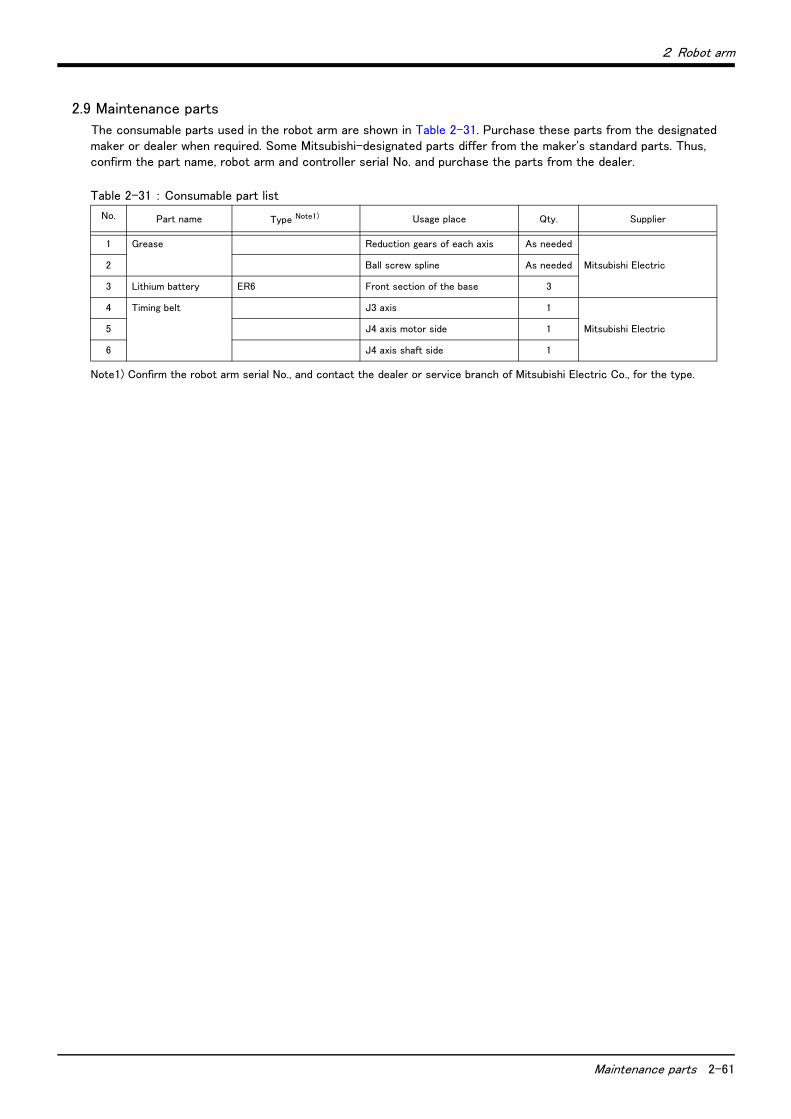
2 Robot arm
Maintenance parts 2-61
2.9 Maintenance parts
The consumable parts used in the robot arm are shown in Table 2-31. Purchase these parts from the designated maker or dealer when required. Some Mitsubishi-designated parts differ from the maker's standard parts. Thus, confirm the part name, robot arm and controller serial No. and purchase the parts from the dealer.
Table 2-31 : Consumable part list
No. Part name Type Note1)
Note1) Confirm the robot arm serial No., and contact the dealer or service branch of Mitsubishi Electric Co., for the type.
Usage place Qty. Supplier
1 Grease Reduction gears of each axis As needed
Mitsubishi Electric 2 Ball screw spline As needed
3 Lithium battery ER6 Front section of the base 3
4 Timing belt J3 axis 1
Mitsubishi Electric 5 J4 axis motor side 1
6 J4 axis shaft side 1
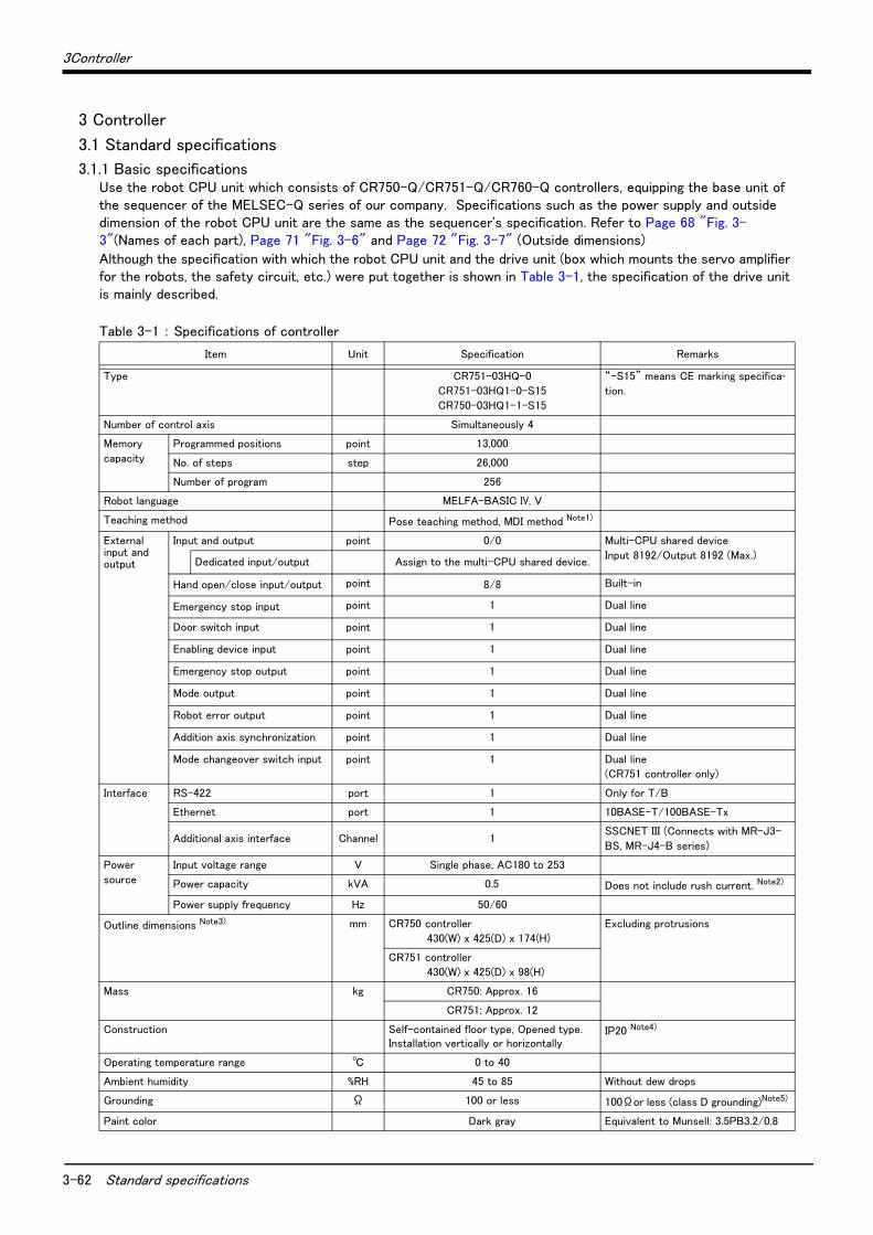
3-62 Standard specifications
3Controller
3 Controller
3.1 Standard specifications
3.1.1 Basic specificationsUse the robot CPU unit which consists of CR750-Q/CR751-Q/CR760-Q controllers, equipping the base unit of the sequencer of the MELSEC-Q series of our company. Specifications such as the power supply and outside dimension of the robot CPU unit are the same as the sequencer's specification. Refer to Page 68 "Fig. 3-3"(Names of each part), Page 71 "Fig. 3-6" and Page 72 "Fig. 3-7" (Outside dimensions)
Although the specification with which the robot CPU unit and the drive unit (box which mounts the servo amplifier for the robots, the safety circuit, etc.) were put together is shown in Table 3-1, the specification of the drive unit is mainly described.
Table 3-1 : Specifications of controller
Item Unit Specification Remarks
Type CR751-03HQ-0
CR751-03HQ1-0-S15
CR750-03HQ1-1-S15
“-S15” means CE marking specifica-tion.
Number of control axis Simultaneously 4
Memory
capacity
Programmed positions point 13,000
No. of steps step 26,000
Number of program 256
Robot language MELFA-BASIC IV, V
Teaching method Pose teaching method, MDI method Note1)
External input and output
Input and output point 0/0 Multi-CPU shared device
Input 8192/Output 8192 (Max.)Dedicated input/output Assign to the multi-CPU shared device.
Hand open/close input/output point 8/8 Built-in
Emergency stop input point 1 Dual line
Door switch input point 1 Dual line
Enabling device input point 1 Dual line
Emergency stop output point 1 Dual line
Mode output point 1 Dual line
Robot error output point 1 Dual line
Addition axis synchronization point 1 Dual line
Mode changeover switch input point 1 Dual line
(CR751 controller only)
Interface RS-422 port 1 Only for T/B
Ethernet port 1 10BASE-T/100BASE-Tx
Additional axis interface Channel 1SSCNET III (Connects with MR-J3-
BS, MR-J4-B series)
Power
source
Input voltage range V Single phase, AC180 to 253
Power capacity kVA 0.5 Does not include rush current. Note2)
Power supply frequency Hz 50/60
Outline dimensions Note3) mm CR750 controller
430(W) x 425(D) x 174(H)
Excluding protrusions
CR751 controller
430(W) x 425(D) x 98(H)
Mass kg CR750: Approx. 16
CR751: Approx. 12
Construction Self-contained floor type, Opened type.Installation vertically or horizontally
IP20 Note4)
Operating temperature range ℃ 0 to 40
Ambient humidity %RH 45 to 85 Without dew drops
Grounding Ω 100 or less 100Ωor less (class D grounding)Note5)
Paint color Dark gray Equivalent to Munsell: 3.5PB3.2/0.8
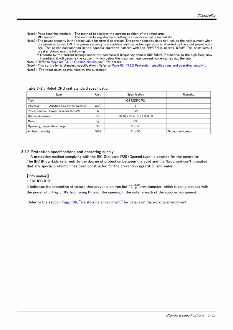
3Controller
Standard specifications 3-63
Table 3-2 : Robot CPU unit standard specification
3.1.2 Protection specifications and operating supplyA protection method complying with the IEC Standard IP20 (Opened type) is adopted for the controller.
The IEC IP symbols refer only to the degree of protection between the solid and the fluids, and don't indicated that any special protection has been constructed for the prevention against oil and water.
【Information】
・ The IEC IP20
It indicates the protective structure that prevents an iron ball 12 0+0.05mm diameter, which is being pressed with
the power of 3.1 kg±10%, from going through the opening in the outer sheath of the supplied equipment.
Refer to the section Page 134, "6.2 Working environment" for details on the working environment.
Note1) Pose teaching method: The method to register the current position of the robot arm.MDI method: The method to register by inputting the numerical value Immediate.
Note2) The power capacity is the rating value for normal operation. The power capacity does not include the rush current whenthe power is turned ON. The power capacity is a guideline and the actual operation is affected by the input power volt-age. The power consumption in the specific operation pattern with the RH-3FH is approx. 0.3kW. The short circuitbreaker should use the following.* Operate by the current leakage under the commercial frequency domain (50-60Hz). If sensitive to the high frequency
ingredient, it will become the cause in which below the maximum leak current value carries out the trip.Note3) Refer to Page 69, "3.3.1 Outside dimensions" for details.Note4) This controller is standard specification. (Refer to Page 63, "3.1.2 Protection specifications and operating supply".)Note5) The robot must be grounded by the customer.
Item Unit Specification Remarks
Type Q172DRCPU
Interface Addition axis synchronization port 1
Power source Power capacity (DC5V) A 1.25
Outline dimension mm 98(W) x 27.4(D) x 119.3(H)
Mass kg 0.33
Operating temperature range ℃ 0 to 55
Ambient humidity %RH 5 to 95 Without dew drops
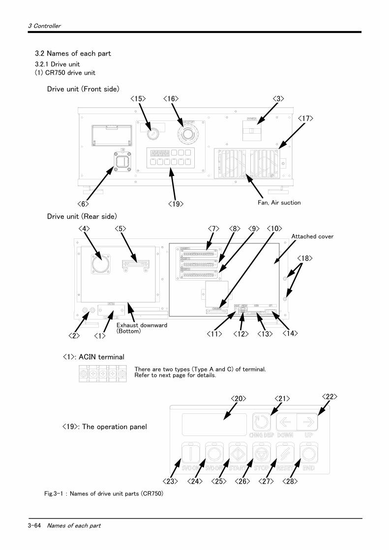
3-64 Names of each part
3 Controller
3.2 Names of each part
3.2.1 Drive unit(1) CR750 drive unit
Fig.3-1 : Names of drive unit parts (CR750)
<19>: The operation panel
Drive unit (Front side)
Drive unit (Rear side)
<6>
<15> <16> <3>
<17>
<19> Fan, Air suction
<7> <10><8> <9>
<1><2>
<18>
Attached cover
Exhaust downward(Bottom)
<5><4>
<13><12><11> <14>
<23> <24> <25> <26> <27> <28>
<22><21><20>
<1>: ACIN terminal
There are two types (Type A and C) of terminal.Refer to next page for details.

3 Controller
Names of each part 3-65
<1> ACIN terminal ................................................The terminal box for AC power source (single phase, AC200V) input. (Inner side of a cover)There are two types of the terminal and the terminal differs depending on the specification (CE or non-CE).
Refer to a separate manual “INSTRUCTION MANUAL/Controller setup, basic operation, and maintenance” for how to connect a power cable.
<2> PE terminal .....................................................The screw for grounding of the cable. (M4 screw x 2 place)<3> Power switch .................................................This turns the control power ON/OFF. (With earth leakage breaker function)
<4> Machine cable connector (motor signal) (CN1)
Connect with the CN1 connector of the robot arm.<5> Machine cable connector (motor power) (CN2)
Connect with the CN2 connector of the robot arm.<6> T/B connection connector (TB) ...........This is a dedicated connector for connecting the T/B. When not using T/
B, connect the attached dummy connector.<7><8><9><10> CNUSR connector ..............The connector for input/ output connection dedicated for robot. (a plug
connector attached)<7>: CNUSR11, <8>: CNUSR12, <9>: CNUSR13, <10>: CNUSR2Refer to a separate manual “INSTRUCTION MANUAL/Controller setup, basic operation, and maintenance” for the connection method and the further description of pin assign.Note) <9>: CNUSR13 connector is not used in this controller.
<11> DCOUT connector (DCOUT)........... For emergency stop <12> CNDISP connector (CNDISP) ........... For LAN of T/B connection<13> CON3 connector (CON3).................. For RS422 of T/B connection<14> OPT connector (OPT)........................ For SSCNETIII connection<15> Mode key switch ................................... This key switch changes the robot's operation mode.
AUTOMATIC ..........Operations from the controller or external equipment are valid. Operations for which the operation mode must be at the external device or T/B are not possible. (Exclude the start of automatic operation.)
MANUAL ..................When the T/B is valid, only operations from the T/B are valid. Operations for which the operation mode must be at the external device or controller are not possible.
<16> Emergency stop switch...................... This switch stops the robot in an emergency state. The servo turns OFF.<17> Filter cover.............................................. There is an air filter inside the cover.<18> Grounding terminal............................... The grounding terminal for connecting cables of option card. (M3 screw x 2
places)<19> Operation panel ..................................... The operation panel for servo ON/OFF, START/STOP the program etc.<20> Display panel (STATUS.NUMBER) ........... The alarm No., program No., override value (%), etc., are displayed.<21> CHNGDISP button ............................... This button changes the details displayed on the display panel in the order
of "Override" → "Line No." → "Program No." → "User information." →"Maker information..
<22> UP/DOWN button............................... This scrolls up or down the details displayed on the "STATUS. NUMBER" display panel.
<23> SVO.ON button ..................................... This turns ON the servo power. (The servo turns ON.)<24> SVO.OFF button.................................. This turns OFF the servo power. (The servo turns OFF.)<25> START button........................................ This executes the program and operates the robot. The program is run
continuously.<26> STOP button .......................................... This stops the robot immediately. The servo does not turn OFF.<27> RESET button ........................................ This resets the error. This also resets the program's halted state and
resets the program.<28> END button ............................................. This stops the program being executed at the last line or End statement.
Specification Non-CE specification CE specification
Type of ACIN terminal
Type A: For single phase
Connect the primary power supply to L1 and L2 terminal.
Type C: For single phase
Connect the primary power supply to L1 and N terminal.
L1 L2 L1 N
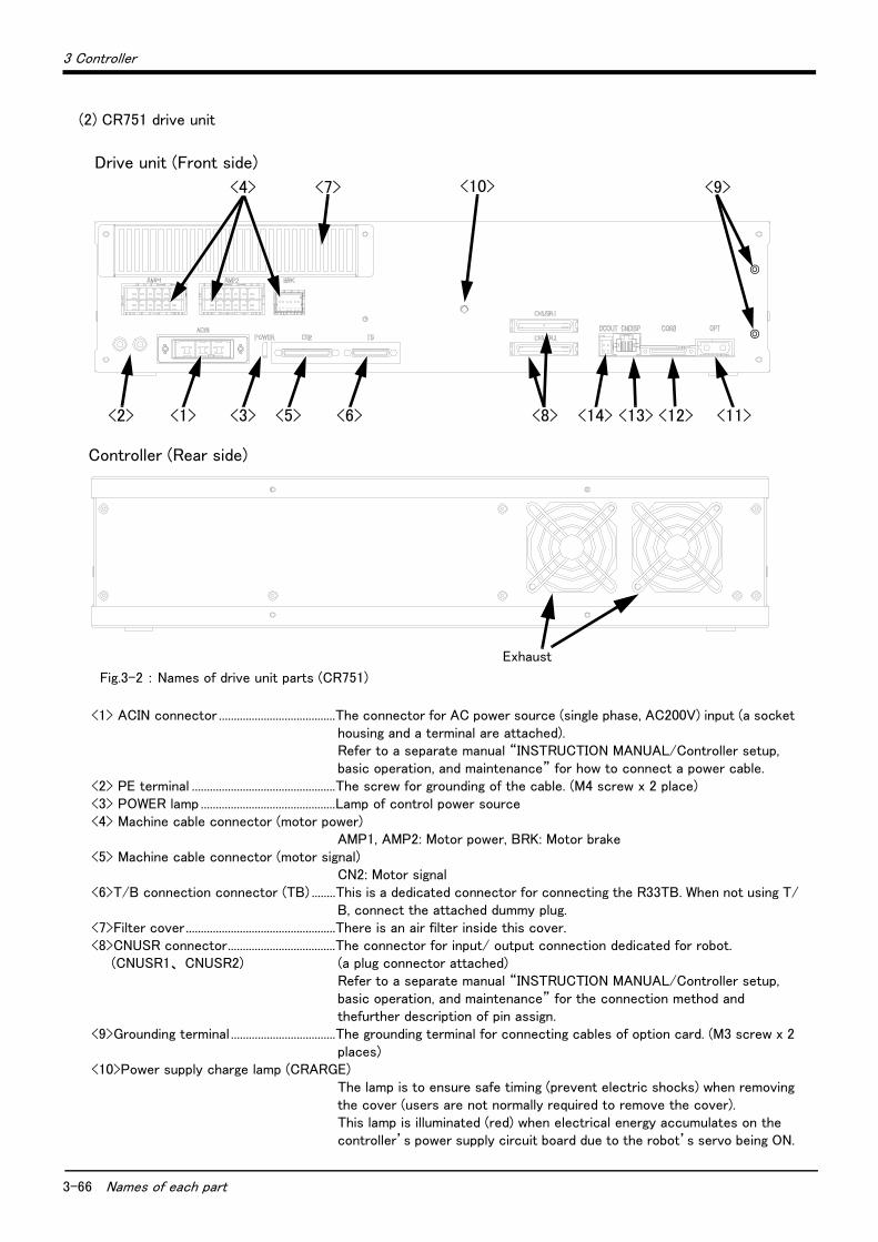
3-66 Names of each part
3 Controller
(2) CR751 drive unit
Fig.3-2 : Names of drive unit parts (CR751)
<1> ACIN connector .......................................The connector for AC power source (single phase, AC200V) input (a socket housing and a terminal are attached).Refer to a separate manual “INSTRUCTION MANUAL/Controller setup, basic operation, and maintenance” for how to connect a power cable.
<2> PE terminal ................................................The screw for grounding of the cable. (M4 screw x 2 place)<3> POWER lamp .............................................Lamp of control power source<4> Machine cable connector (motor power)
AMP1, AMP2: Motor power, BRK: Motor brake<5> Machine cable connector (motor signal)
CN2: Motor signal<6>T/B connection connector (TB) ........This is a dedicated connector for connecting the R33TB. When not using T/
B, connect the attached dummy plug.<7>Filter cover..................................................There is an air filter inside this cover.<8>CNUSR connector....................................The connector for input/ output connection dedicated for robot.
(CNUSR1、 CNUSR2) (a plug connector attached)Refer to a separate manual “INSTRUCTION MANUAL/Controller setup, basic operation, and maintenance” for the connection method and thefurther description of pin assign.
<9>Grounding terminal ...................................The grounding terminal for connecting cables of option card. (M3 screw x 2 places)
<10>Power supply charge lamp (CRARGE)The lamp is to ensure safe timing (prevent electric shocks) when removing the cover (users are not normally required to remove the cover). This lamp is illuminated (red) when electrical energy accumulates on the controller’s power supply circuit board due to the robot’s servo being ON.
<2> <1> <3>
<4> <7> <9>
<5> <6> <14> <13> <12> <11><8>
<10>
Drive unit (Front side)
Exhaust
Controller (Rear side)
3 Controller
Names of each part 3-67
After turning the control power OFF and allowing a few minutes to pass, the lamp will go out.
<11>OPT connector (OPT) .........................For SSCNETIII connection<12>CON3 connector (CON3) ...................For RS422 of T/B connection<13>CNDISP connector (CNDISP) ..........For LAN of T/B connection<14>DCOUT connector (DCOUT) ............For emergency stop

3-68 Names of each part
3 Controller
3.2.2 Robot CPU
Fig.3-3 : Names of each part of the robot CPU
① Seven segments LED......................Indicates operational status and error information② Rotary switch (SW1)........................Set up operation mode. Always set it as "0." ③ Rotary switch (SW2)........................Set up operation mode. Always set it as "0." ④ RUN/STOP switch...........................Unused
⑤ Emergency stop input (EMI)*1) ...Connects with the connector (DCOUT) of the controller by the EMI cable forrobot. (For the emergency stops)
⑥ CN1 connector*2) ............................Connects with the connector (OPT) of the controller by the SSCNET III cablefor robot. (For the robot-arm servo amplifier connection)
⑦ CN2 connector*2) ............................Connect to the servo amplifier of the addition axis (Eight axes)⑧ Lever for unit installation ..............Use this lever, when installing the unit in the base unit.
⑨ Hook for unit fixing*3) .....................The hook which fixes the unit to the base unit (For the support at installation)⑩ Unit fixing screw................................The screw for fixing to the base unit (M3×13)⑪ The projection for unit fixing ......The projection for fixing to the base unit ⑫ Battery connector (BAT)*4) ........The connector for connection with battery holder unit Q170DBATC.⑬ The connector for the networks (DISPLAY I/F)
Connects with the connector (CNDISP) of the controller by the DISP cable forrobot. (For the LAN of T/B)
⑭ RS422 connector (TU I/F)............Connects with the connector (CON3) of the controller by the TU cable forrobot. (For the RS-422 of T/B)
*1) Please be sure to use the emergency stop input cable. The emergency stop cannot be canceled if it does notuse. If it manufactures the emergency stop input cable in the customer, cable length should use 30m or less.
*2) Please store in the duct or fix the cable section near robot CPU with the bunch wire rod so that prudence ofthe cable is not applied to CN1 and CN2 connector section.
*3) It is equipment for the support when installing the unit in the basic base unit. Please be sure to fix the unit tothe basic base unit with the attached fixing screw.
*4) Please be sure to use the external battery. Unless the battery cable is connected surely, the program inSRAM with a built-in robot CPU, the parameter, origin position data, etc. are not held.
⑦
⑥
8
4
0
C
0
8
C
4
BATFRONT
CN
2C
N1
EMICAUTION
STOP RUN1 2
SW
Q172DRCPU
ACFAILRIO
MPG
TU
I/
FD
ISP
LA
Y
I/F
①
③②
④
⑤
⑧
⑨⑩
⑪
⑫
背面 側面 正面
⑬
⑭
SideBack Front

3 Controller
Outside dimensions/Installation dimensions 3-69
3.3 Outside dimensions/Installation dimensions
3.3.1 Outside dimensions(1) CR750 drive unit
Fig.3-4 : Outside dimensions of drive unit (CR750)
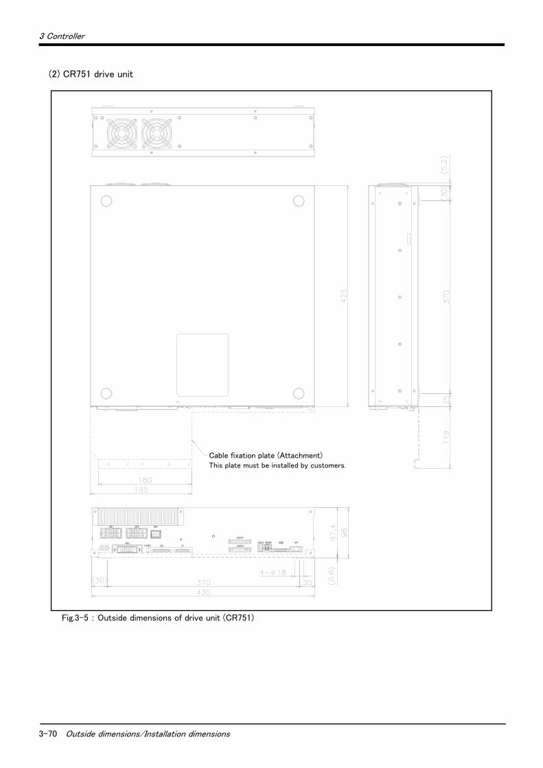
3-70 Outside dimensions/Installation dimensions
3 Controller
(2) CR751 drive unit
Fig.3-5 : Outside dimensions of drive unit (CR751)
Cable fixation plate (Attachment)This plate must be installed by customers.
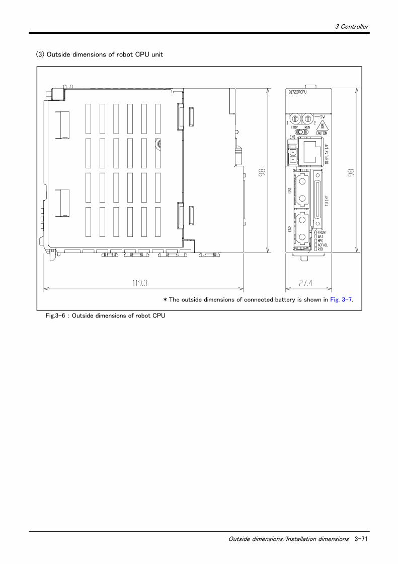
3 Controller
Outside dimensions/Installation dimensions 3-71
(3) Outside dimensions of robot CPU unit
Fig.3-6 : Outside dimensions of robot CPU
* The outside dimensions of connected battery is shown in Fig. 3-7.

3-72 Outside dimensions/Installation dimensions
3 Controller
(4) Battery unit outside dimension
Fig.3-7 : Outside dimensions of battery unit
2-Φ5.5 hole
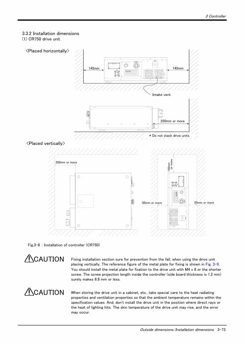
3 Controller
Outside dimensions/Installation dimensions 3-73
3.3.2 Installation dimensions(1) CR750 drive unit
Fig.3-8 : Installation of controller (CR750)
Fixing installation section sure for prevention from the fall, when using the drive unit placing vertically. The reference figure of the metal plate for fixing is shown in Fig. 3-9.
You should install the metal plate for fixation to the drive unit with M4 x 8 or the shorter screw. The screw projection length inside the controller (side board thickness is 1.2 mm) surely makes 6.8 mm or less.
When storing the drive unit in a cabinet, etc., take special care to the heat radiating properties and ventilation properties so that the ambient temperature remains within the specification values. And, don't install the drive unit in the position where direct rays or the heat of lighting hits. The skin temperature of the drive unit may rise, and the error may occur.
150m
m以
上
50mm以上 20mm以上
250mm以上
145mm 145mm
250mm以上
吸気口
<Placed horizontally>
<Placed vertically>
Intake vent
250mm or more
50mm or more 20mm or more
150
mm
or
more
250mm or more
* Do not stack drive units.
CAUTION
CAUTION
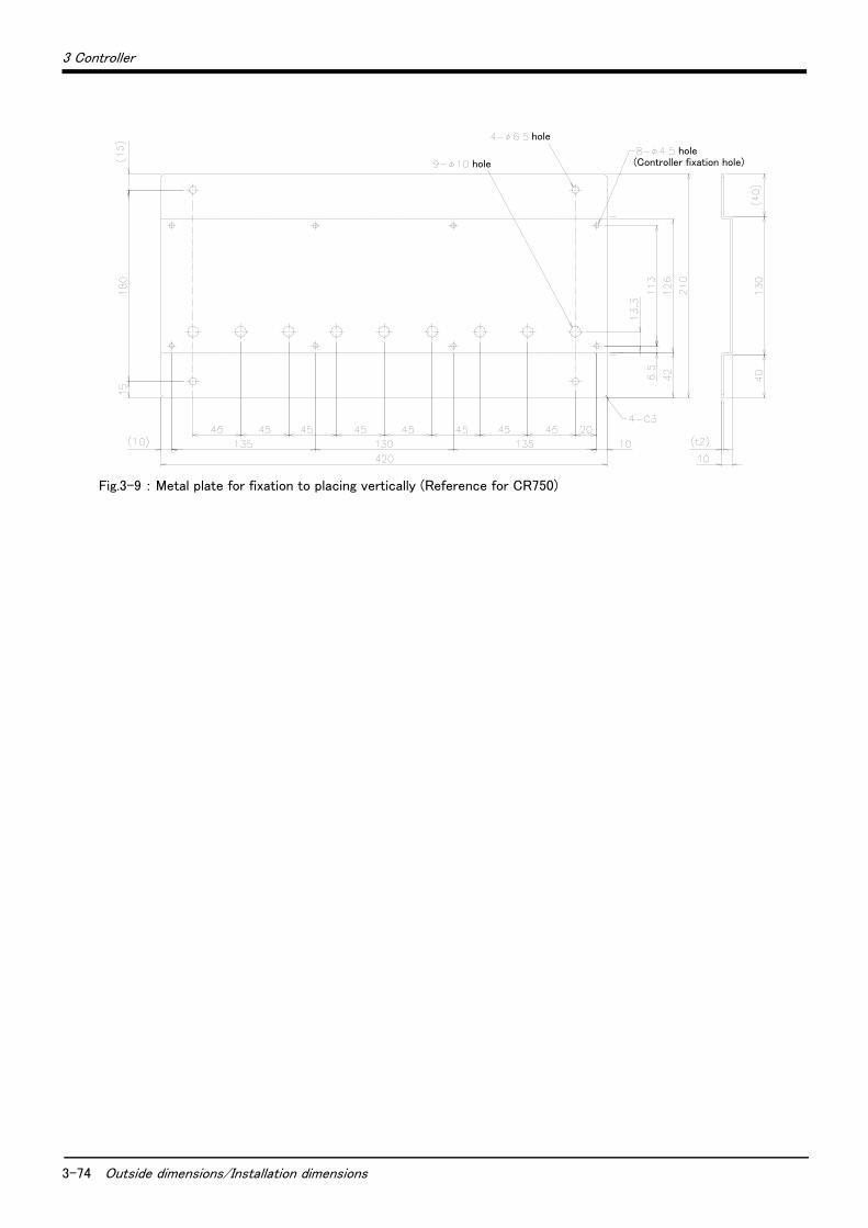
3-74 Outside dimensions/Installation dimensions
3 Controller
Fig.3-9 : Metal plate for fixation to placing vertically (Reference for CR750)
hole(Controller fixation hole)
hole
hole
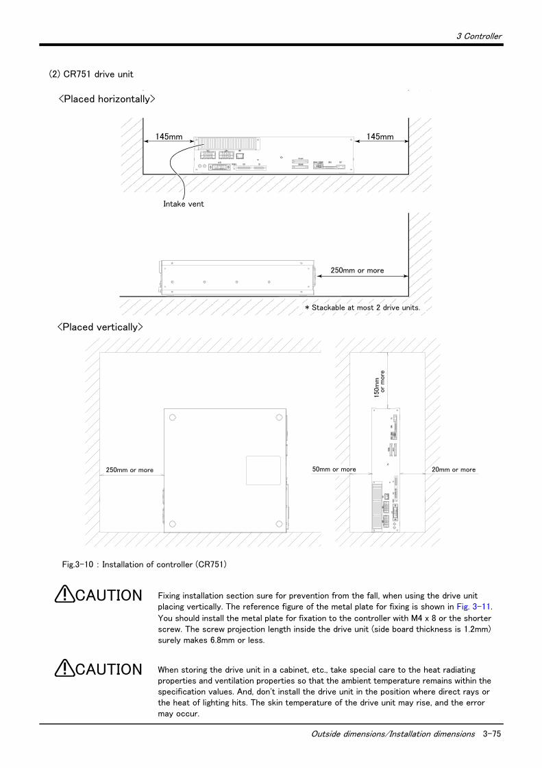
3 Controller
Outside dimensions/Installation dimensions 3-75
(2) CR751 drive unit
Fig.3-10 : Installation of controller (CR751)
Fixing installation section sure for prevention from the fall, when using the drive unit placing vertically. The reference figure of the metal plate for fixing is shown in Fig. 3-11.
You should install the metal plate for fixation to the controller with M4 x 8 or the shorter screw. The screw projection length inside the drive unit (side board thickness is 1.2mm) surely makes 6.8mm or less.
When storing the drive unit in a cabinet, etc., take special care to the heat radiating properties and ventilation properties so that the ambient temperature remains within the specification values. And, don't install the drive unit in the position where direct rays or the heat of lighting hits. The skin temperature of the drive unit may rise, and the error may occur.
150m
m以
上
50mm以上 20mm以上250mm以上
145mm
250mm以上
吸気口
145mm
<Placed vertically>
Intake vent
250mm or more
250mm or more 50mm or more 20mm or more
150m
m
or
more
<Placed horizontally>
* Stackable at most 2 drive units.
CAUTION
CAUTION
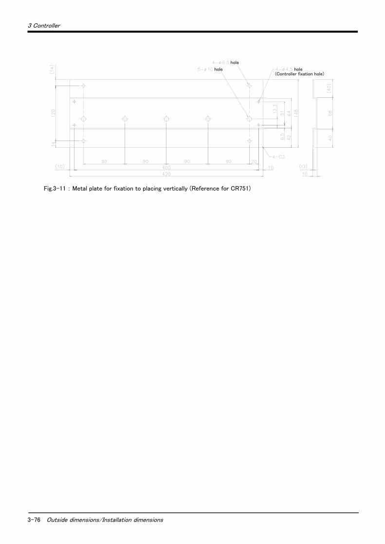
3-76 Outside dimensions/Installation dimensions
3 Controller
Fig.3-11 : Metal plate for fixation to placing vertically (Reference for CR751)
hole
hole hole(Controller fixation hole)

3 Controller
Outside dimensions/Installation dimensions 3-77
(3) Robot CPU Unit installation dimensionsBecause to improve ventilation and to make unit replacement easy, please secure the following distance
between the upper and lower sides of the unit and the structure, etc.
Fig.3-12 : Installation of robot CPU Unit
40mm以上
5mm以上 5mm以上
100mm以上
盤の天井、配線ダクト部分の位置
盤
扉
ロボットCPUユニット
100mm以上
123.5mm
ベースユニット
I / O11I/O11
Q312DB
QX400 1 2 3 4 5 6 78 9 A B C D E F
SY.ENC1
Q172DEX
Q172DEX
2
1 TRENSY.ENC2
1
Q173DPX
PULSER
Q173DPX PLS.A
3
2
1
PLS.B
3
2
1 TREN
321
MELSEC
Q61P POWER
PULL
Q03DCPU
USER
MODERUNERR.
BAT.BOOT
PULL
USB
RS-232
QX400 1 2 3 4 5 6 78 9 A B C D E F
<Q172DRCPU>
8
4
0
C
0
8
C
4
BA TFR ONT
CN
2C
N1
E M ICAUTION
STOP RUN1 2
SW
Q172DRCPU
ACFAILRIO
M PG
TU
I/
FD
ISP
LAY
I/
F
ロボットCPUユニット
The position of the ceiling of the board, and the wiring duct section
Base unit
Robot CPU Unit Robot CPU Unit
Board
Door
Within 5mm Within 5mm
Within 100mm
Within 40mm
Within 100mm
123.5mm

3-78 External input/output
3 Controller
3.4 External input/output
3.4.1 Types(1) Dedicated input/output .............................. These inputs and outputs carry out the robot remote operation and
status display.(2) General-purpose input/output ................ These are inputs and outputs that the customer can program for
peripheral device control.(3) Hand input/output ........................................ These are inputs and outputs related to the hand that the customer
can program.(4)Emergency stop/Door switch input........ The wiring for the safe security of the emergency stop etc. is shown in
on Page 82, "3.6 Emergency stop input and output etc." and on Page 121, "6.1.7 Examples of safety measures".
<For Reference>
Linking our GOT1000 Series (GT15) display equipment to the robot controller over the Ethernet permits you to control robot controller's input/output from a GOT (graphic operation terminal).

3 Controller
Dedicated input/output 3-79
3.5 Dedicated input/output
Show the main function of dedicated input/output in the Table 3-3. Refer to attached instruction manual "Detailed explanations of functions and operations" in the product for the other functions. Each parameter indi-cated with the parameter name is used by designated the signal No., assigned in the order of input signal No. and output signal No.
Table 3-3 : Dedicated input/output list
Parameter name
Input Note1) Output
Name Function Level Name Function
TEACHMD None Teaching mode out-put signal
Outputs that the teaching mode is
entered.
ATTOPMD None Automatic mode out-put signal
Outputs that the automatic mode is
entered.
ATEXTMD None Remote mode output
signal
Outputs that the remote mode is
entered.
RCREADY None Controller power ON
complete signal
Outputs that external input signals can
be received.
AUTOENA Automatic opera-tion enabled input
signal
Allows automatic operation.
L
Automatic operation
enabled output signal
Outputs the automatic operation
enabled state.
START Start input signal Starts all slots.E
Operating output sig-nal
Outputs that the slot is operating.
STOP Stop input signal Stops all slots.
The input signal No. is fixed to 0.
Note) Use the emergency stop
input for stop inputs related
to safety.
L
Wait output signal Outputs that the slot is temporarily
stopped.
STOP2 Stop input signal The program during operation is
stopped.
Unlike the STOP parameter,
change of the signal number is
possible.
Notes) Specification is the same as
the STOP parameter.
L
Wait output signal Outputs that the slot is temporarily
stopped.
Notes) Specification is the same as the
STOP parameter.
SLOTINIT Program reset input
signal
Resets the wait state.E
Program selection
enabled output signal
Outputs that the slot is in the program
selection enabled state.
ERRRESET Error reset input
signal
Resets the error state.E
Error occurring out-put signal
Outputs that an error has occurred.
CYCLE Cycle stop input
signal
Carries out cycle stop.E
In cycle stop opera-tion output signal
Outputs that the cycle stop is operat-ing.
SRVOFF Servo ON enabled
input signal
Turns the servo OFF for all mech-anisms.
LServo ON enabled
output signal
Outputs servo-on disable status.
(Echo back)
SRVON Servo ON input
signal
Turns the servo ON for all mecha-nisms.
EIn servo ON output
signal
Outputs the servo ON state.
IOENA Operation rights
input signal
Requests the operation rights for
the external signal control.L
Operation rights out-put signal
Outputs the operation rights valid state
for the external signal control.
MELOCK Machine lock input
signal
Sets/resets the machine lock
state for all mechanisms.E
In machine lock out-put signal
Outputs the machine lock state.
SAFEPOS Evasion point
return input signal
Requests the evasion point return
operation.E
In evasion point
return output signal
Outputs that the evasion point return
is taking place.
OUTRESET General-purpose
output signal reset
Resets the general-purpose output
signal.E None
EMGERRNone
Emergency stop out-put signal
Outputs that an emergency stop has
occurred.
S1START
:
S32START
Start input Starts each slot. E In operation outputOutputs the operating state for each
slot.
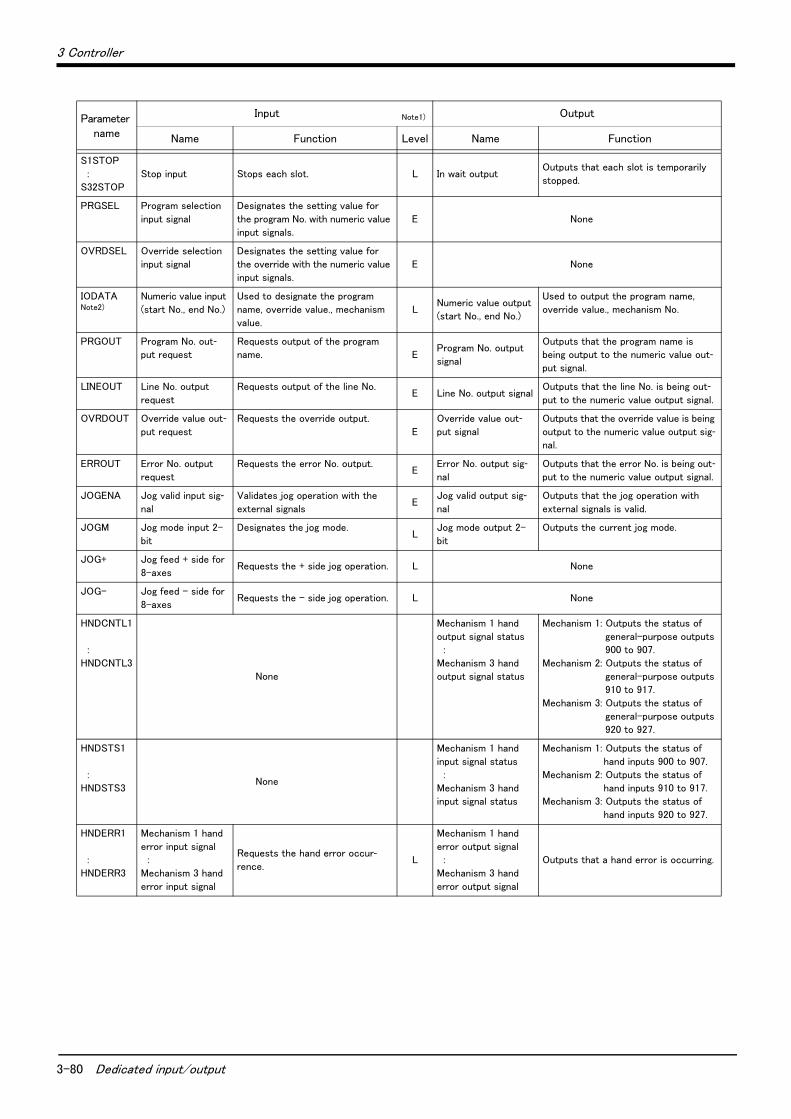
3-80 Dedicated input/output
3 Controller
S1STOP
:
S32STOP
Stop input Stops each slot. L In wait outputOutputs that each slot is temporarily
stopped.
PRGSEL Program selection
input signal
Designates the setting value for
the program No. with numeric value
input signals.
E None
OVRDSEL Override selection
input signal
Designates the setting value for
the override with the numeric value
input signals.
E None
IODATANote2)
Numeric value input
(start No., end No.)
Used to designate the program
name, override value., mechanism
value.
LNumeric value output
(start No., end No.)
Used to output the program name,
override value., mechanism No.
PRGOUT Program No. out-put request
Requests output of the program
name. EProgram No. output
signal
Outputs that the program name is
being output to the numeric value out-put signal.
LINEOUT Line No. output
request
Requests output of the line No.E Line No. output signal
Outputs that the line No. is being out-put to the numeric value output signal.
OVRDOUT Override value out-put request
Requests the override output.
E
Override value out-put signal
Outputs that the override value is being
output to the numeric value output sig-nal.
ERROUT Error No. output
request
Requests the error No. output.E
Error No. output sig-nal
Outputs that the error No. is being out-put to the numeric value output signal.
JOGENA Jog valid input sig-nal
Validates jog operation with the
external signalsE
Jog valid output sig-nal
Outputs that the jog operation with
external signals is valid.
JOGM Jog mode input 2-
bit
Designates the jog mode.L
Jog mode output 2-
bit
Outputs the current jog mode.
JOG+ Jog feed + side for
8-axesRequests the + side jog operation. L None
JOG- Jog feed - side for
8-axesRequests the - side jog operation. L None
HNDCNTL1
:
HNDCNTL3
None
Mechanism 1 hand
output signal status
:
Mechanism 3 hand
output signal status
Mechanism 1: Outputs the status of
general-purpose outputs
900 to 907.
Mechanism 2: Outputs the status of
general-purpose outputs
910 to 917.
Mechanism 3: Outputs the status of
general-purpose outputs
920 to 927.
HNDSTS1
:
HNDSTS3 None
Mechanism 1 hand
input signal status
:
Mechanism 3 hand
input signal status
Mechanism 1: Outputs the status of
hand inputs 900 to 907.
Mechanism 2: Outputs the status of
hand inputs 910 to 917.
Mechanism 3: Outputs the status of
hand inputs 920 to 927.
HNDERR1
:
HNDERR3
Mechanism 1 hand
error input signal
:
Mechanism 3 hand
error input signal
Requests the hand error occur-rence.
L
Mechanism 1 hand
error output signal
:
Mechanism 3 hand
error output signal
Outputs that a hand error is occurring.
Parameter name
Input Note1) Output
Name Function Level Name Function
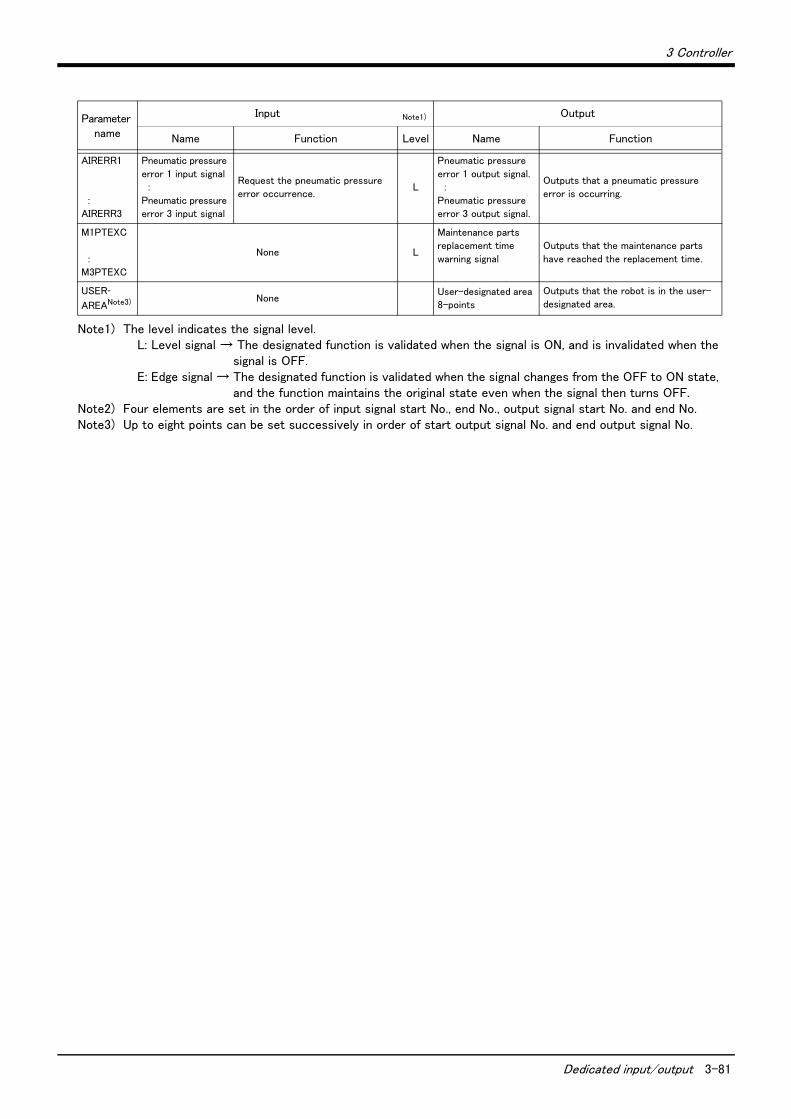
3 Controller
Dedicated input/output 3-81
AIRERR1
:
AIRERR3
Pneumatic pressure
error 1 input signal
:
Pneumatic pressure
error 3 input signal
Request the pneumatic pressure
error occurrence.L
Pneumatic pressure
error 1 output signal.
:
Pneumatic pressure
error 3 output signal.
Outputs that a pneumatic pressure
error is occurring.
M1PTEXC
:
M3PTEXC
None L
Maintenance parts
replacement time
warning signal
Outputs that the maintenance parts
have reached the replacement time.
USER-AREANote3) None
User-designated area
8-points
Outputs that the robot is in the user-
designated area.
Note1) The level indicates the signal level.L: Level signal → The designated function is validated when the signal is ON, and is invalidated when the
signal is OFF.E: Edge signal → The designated function is validated when the signal changes from the OFF to ON state,
and the function maintains the original state even when the signal then turns OFF.Note2) Four elements are set in the order of input signal start No., end No., output signal start No. and end No.Note3) Up to eight points can be set successively in order of start output signal No. and end output signal No.
Parameter name
Input Note1) Output
Name Function Level Name Function
3-82 Emergency stop input and output etc.
3 Controller
3.6 Emergency stop input and output etc.
Do wiring of the external emergency stop, the special stop input, the door switch, and the enabling device from the "special input/output" terminal connector.
Table 3-4 : Special input/output terminal
*At the time of the power supply OFF, the output point of contact is always open.
[Note] The contact capacity of each input/output terminal is DC24V/10mA - 100mA. Don't connect the equipment except for this range. The use exceeding contact capacity causes failure.In the customer's system, do not ground the + side of 24V power supply prepared by customer for connect to the controller. (related with emergency stop and parallel input/output) If it connects with the controller under the condition that the + side is grounded, it will lead to failure of controller.
[Note] If a stop signal or servo OFF signal is input simultaneously with a door switch open/emergency stop input, the error, H056n “Servo sys. error (A/D)” may occur. When a door switch open/emergency stop is input, the robot turns off the servo after it stops. It is unnecessary to input a stop signal or servo OFF signal. To input a stop signal or servo OFF signal with a door switch open/emergency stop input, wait for 100ms or more after a door switch open/emergency stop input.
Pin number assignment of each terminal and the circuit diagram are shown in Fig. 3-14 (CR750) or Fig. 3-18 (CR751).
3.6.1 Connection of the external emergency stopThe external emergency stop input and door switch input and enabling device input are opened at shipment as shown in Fig. 3-14 (CR750) or Fig. 3-18 (CR751).Connect the external emergency stop switch and door switch with the following procedure.
And, the example of the connection and notes of the emergency stop are described in Page 121, "6.1.7 Examples of safety measures" Refer to it together
[Caution] The emergency stop circuit is duplicated inside the drive unit. The emergency stop switch uses a doublecontact-type switch, so please be sure to fix both of the contacts to the connector pins as shown belowin order to ensure the wiring is duplicated. An error will continue to occur in the event that only one ofthe pins is connected.
1) Please prepare the emergency stop switch, door switch and enabling device.a) External emergency switch
・ CR750 drive unit ...........CNUSR11 connector "between 3 and 4" and CNUSR12 Connector "between 3 and 4".・ CR751 drive unit ...........CNUSR1 connector "between 2 and 27" and "between 7 and 32".
b) Door switch・ CR750 drive unit ...........CNUSR11 connector "between 7 and 8" and CNUSR12 connector "between 7 and 8".・ CR751 drive unit ...........CNUSR1 connector "between 4 and 29" and "between 9 and 34".
c) Enabling device・ CR750 drive unit ...........CNUSR11 connector "between 9 and 10" and CNUSR12 connector "between 9 and 10".・ CR751 drive unit ...........CNUSR1 connector "between 5 and 30" and "between 10 and 35".
[Caution] Be sure to use a shield cable for the emergency stop wiring cable. And when operating in an environ-ment that is easily affected by noise, be sure to fix the attached ferrite core (model number:
Item Name Function
Input Emergency stop Applies the emergency stop. Dual emergency line
Input Special stop input Applies the stop. (Refer to Page 90, "3.6.2 Special stop input (SKIP)")
Input Door switch Servo-off. Dual line, normal close (Page 92, "3.6.3 Door switch function")
Input Enabling device Servo-off. Dual line, normal close (Page 92, "3.6.4 Enabling device function")
Output Robot error output Contactor is opening during error occurrence.
Output Emergency stop output The point of contact opens under occurrence of emergency stop of external input signal, emergency
stop of OP, emergency stop of T/B.
Output Mode output MANUAL mode: contactor is opening, AUTOMATIC mode: contactor is closing.
Output Magnet contactor control
connector output for addi-tion axes
When an additional axis is used, the servo ON/OFF status of the additional axis can be synchronized
with the robot arm. (Page 101, "3.9 Magnet contactor control connector output (AXMC) for addition
axes")

3 Controller
Emergency stop input and output etc. 3-83
E04SR301334, manufacturer: Seiwa Electric Mfg. Co., Ltd.). Be sure to place the ferrite core more than30 cm from the connecting terminal section.
Make sure there are no mistakes in the wiring. Connecting differently to the way specified in the manual can result in errors, such as the emergency stop not being released. In order to prevent errors occurring, please be sure to check that all functions (such as the teaching box emergency stop, customer emergency stop, and door switch) are working properly after the wiring setup is completed.
You should always connect doubly connection of the emergency stop, the door switch, and the enabling switch. In connection of only one side, if the relay of customer use should break down, it may not function correctly.And, the output contacts from the robot controller (robot error output, emergency stop output, mode output, addition axis contactor control output) are dual contacts (syn-chronizes). You should connect surely by dual line with the customer's equipment as well as connection of the emergency stop and the door switch.
Please make sure to wire the multiple emergency stop switches so that they each function independently. Check and make sure that the emergency stop doesn't only function under an AND condition (when multiple emergency stop switches are ON at the same time).
(1) CR750 drive unit
Fig.3-13 : Emergency stop cable connection (CR750)
CAUTION
CAUTION
CAUTION
30cm以内
フェライトコア2回通し
CNUSR11コネクタ
CNUSR12コネクタ
CNUSR11 connector
Within 30 cm
Ferrite core
Pass twice
CNUSR12 connector
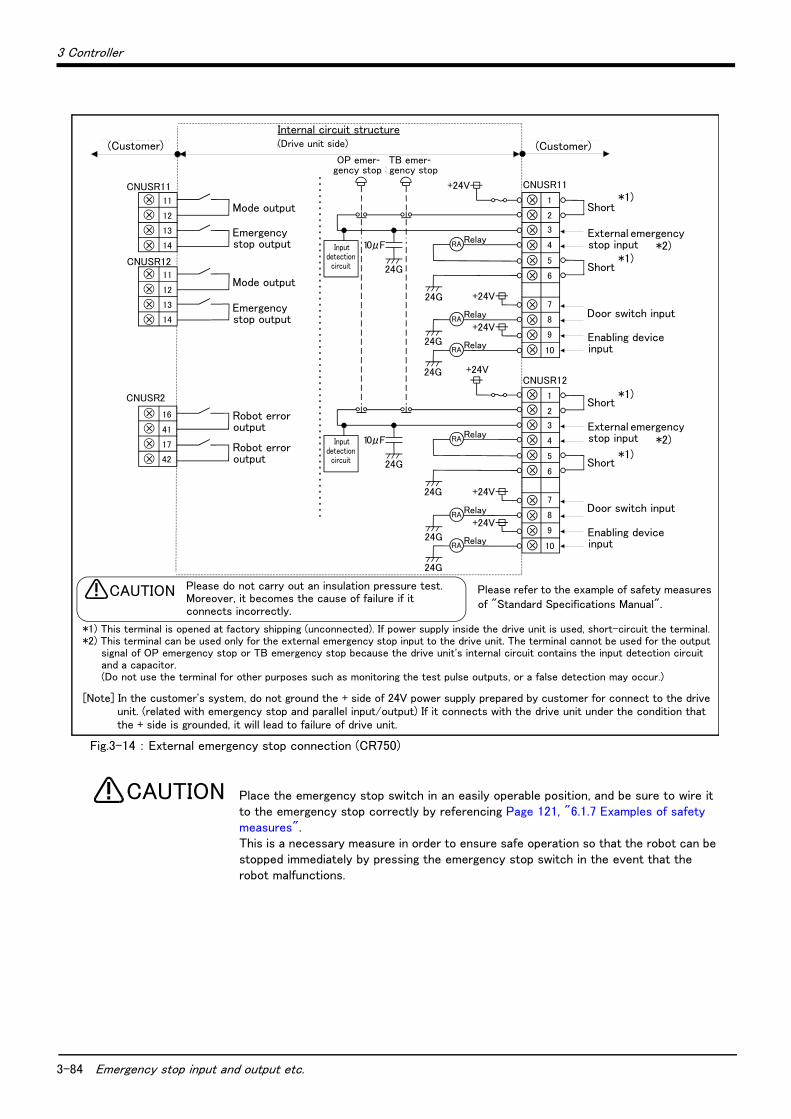
3-84 Emergency stop input and output etc.
3 Controller
Fig.3-14 : External emergency stop connection (CR750)
Place the emergency stop switch in an easily operable position, and be sure to wire it to the emergency stop correctly by referencing Page 121, "6.1.7 Examples of safety measures". This is a necessary measure in order to ensure safe operation so that the robot can be stopped immediately by pressing the emergency stop switch in the event that the robot malfunctions.
CNUSR11
CNUSR2
内部回路構成(お客様配線側) (コントローラ側)
警告 絶縁耐圧試験は行なわないでください。また誤って接続した場合は故障の原因となります。
10
9
8
7
3
4
2
CNUSR11+24V
Relay
+24V
24G
24G
24G
RA+24V
RelayRA
RelayRA
外部非常停止入力
ドアスイッチ入力
イネーブリングデバイス入力
TB非常停止
+24V
Relay
+24V
24G
24G
24G
RA+24V
RelayRA
RelayRA
14
13
12
11
17
41
16
モード出力
非常停止出力
ロボットエラー出力外部非常停止入力
ドアスイッチ入力
イネーブリングデバイス入力
(お客様配線側)
短絡
短絡
短絡
短絡
モード出力
非常停止出力
ロボットエラー出力
CNUSR12
14
13
12
11
1
5
6
10
9
8
7
3
4
2
1
5
6
CNUSR12
OP非常停止
24G
10μF入力検知回路
入力検知回路 24G
10μF
Please refer to the example of safety measures of "Standard Specifications Manual".
内部回路構成(側)
Please do not carry out an insulation pressure test.Moreover, it becomes the cause of failure if it connects incorrectly.
CAUTION
Internal circuit structure(Drive unit side)(Customer) (Customer)
Mode output
Mode output
Robot error output
Robot error output
Emergency stop output
Emergency stop output
Short
External emergency stop input
Short
Door switch input
Enabling device input
Short
External emergency stop input
Short
Door switch input
Enabling device input
TB emer-gency stop
OP emer-gency stop
*1) This terminal is opened at factory shipping (unconnected). If power supply inside the drive unit is used, short-circuit the terminal.*2) This terminal can be used only for the external emergency stop input to the drive unit. The terminal cannot be used for the output
signal of OP emergency stop or TB emergency stop because the drive unit's internal circuit contains the input detection circuit and a capacitor. (Do not use the terminal for other purposes such as monitoring the test pulse outputs, or a false detection may occur.)
*1)
*1)
*1)
*1)
[Note] In the customer's system, do not ground the + side of 24V power supply prepared by customer for connect to the drive unit. (related with emergency stop and parallel input/output) If it connects with the drive unit under the condition that the + side is grounded, it will lead to failure of drive unit.
Input detection
circuit
*2)
*2) Input detection
circuit
CAUTION
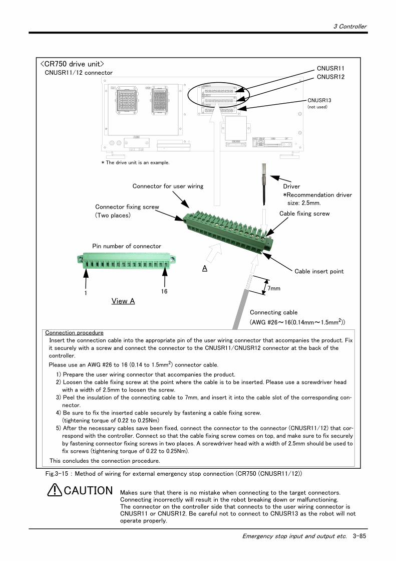
3 Controller
Emergency stop input and output etc. 3-85
Fig.3-15 : Method of wiring for external emergency stop connection (CR750 (CNUSR11/12))
Makes sure that there is no mistake when connecting to the target connectors.Connecting incorrectly will result in the robot breaking down or malfunctioning.The connector on the controller side that connects to the user wiring connector is CNUSR11 or CNUSR12. Be careful not to connect to CNUSR13 as the robot will not operate properly.
CNUSR13 (not used)
<CR750 drive unit>CNUSR11/12 connector
CNUSR11
CNUSR12
Cable fixing screw
Cable insert point
7mm
A
View A
161
Connector fixing screw
(Two places)
Pin number of connector
Connecting cable
(AWG #26~16(0.14mm~1.5mm2))
Connector for user wiring Driver
*Recommendation driver size: 2.5mm.
Connection procedureInsert the connection cable into the appropriate pin of the user wiring connector that accompanies the product. Fix it securely with a screw and connect the connector to the CNUSR11/CNUSR12 connector at the back of the controller.
Please use an AWG #26 to 16 (0.14 to 1.5mm2) connector cable.
1) Prepare the user wiring connector that accompanies the product.2) Loosen the cable fixing screw at the point where the cable is to be inserted. Please use a screwdriver head
with a width of 2.5mm to loosen the screw.3) Peel the insulation of the connecting cable to 7mm, and insert it into the cable slot of the corresponding con-
nector.4) Be sure to fix the inserted cable securely by fastening a cable fixing screw.
(tightening torque of 0.22 to 0.25Nm)5) After the necessary cables save been fixed, connect the connector to the connector (CNUSR11/12) that cor-
respond with the controller. Connect so that the cable fixing screw comes on top, and make sure to fix securely by fastening connector fixing screws in two places. A screwdriver head with a width of 2.5mm should be used to fix screws (tightening torque of 0.22 to 0.25Nm).
This concludes the connection procedure.
* The drive unit is an example.
CAUTION
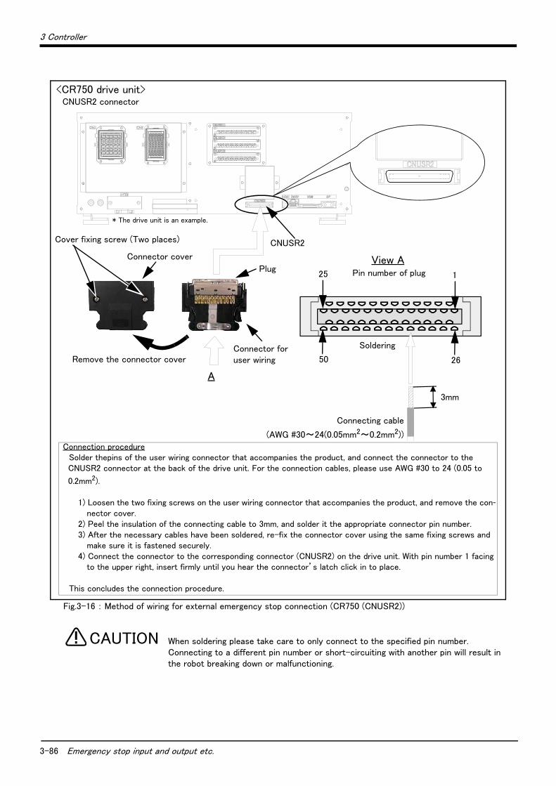
3-86 Emergency stop input and output etc.
3 Controller
Fig.3-16 : Method of wiring for external emergency stop connection (CR750 (CNUSR2))
When soldering please take care to only connect to the specified pin number. Connecting to a different pin number or short-circuiting with another pin will result in the robot breaking down or malfunctioning.
<CR750 drive unit>CNUSR2 connector
CNUSR2
3mm
A
View APlug
Connector cover
Connecting cable
(AWG #30~24(0.05mm2~0.2mm2))
Cover fixing screw (Two places)
Remove the connector cover
Pin number of plug25 1
50 26
SolderingConnector for user wiring
Connection procedureSolder thepins of the user wiring connector that accompanies the product, and connect the connector to the CNUSR2 connector at the back of the drive unit. For the connection cables, please use AWG #30 to 24 (0.05 to
0.2mm2).
1) Loosen the two fixing screws on the user wiring connector that accompanies the product, and remove the con-nector cover.
2) Peel the insulation of the connecting cable to 3mm, and solder it the appropriate connector pin number.3) After the necessary cables have been soldered, re-fix the connector cover using the same fixing screws and
make sure it is fastened securely.4) Connect the connector to the corresponding connector (CNUSR2) on the drive unit. With pin number 1 facing
to the upper right, insert firmly until you hear the connector’s latch click in to place.
This concludes the connection procedure.
* The drive unit is an example.
CAUTION
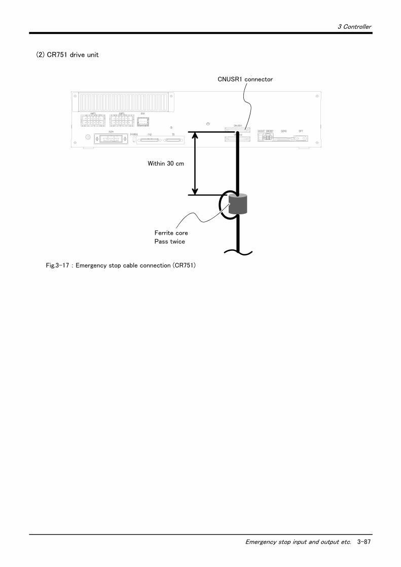
3 Controller
Emergency stop input and output etc. 3-87
(2) CR751 drive unit
Fig.3-17 : Emergency stop cable connection (CR751)
CNUSR1コネクタ
30cm以内
フェライトコア2回通し
CNUSR1 connector
Within 30 cm
Ferrite core
Pass twice
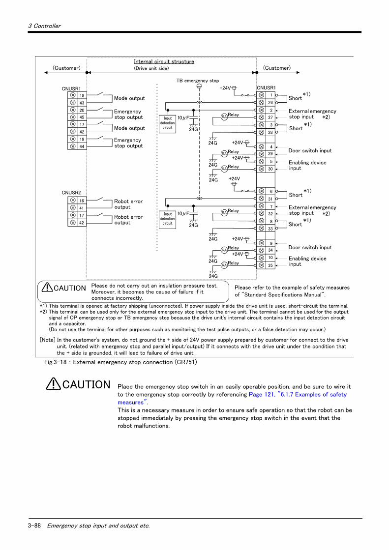
3-88 Emergency stop input and output etc.
3 Controller
Fig.3-18 : External emergency stop connection (CR751)
Place the emergency stop switch in an easily operable position, and be sure to wire it to the emergency stop correctly by referencing Page 121, "6.1.7 Examples of safety measures". This is a necessary measure in order to ensure safe operation so that the robot can be stopped immediately by pressing the emergency stop switch in the event that the robot malfunctions.
CNUSR1
CNUSR2
内部回路構成(お客様配線側) (コントローラ側)
警告 絶縁耐圧試験は行なわないでください。また誤って接続した場合は故障の原因となります。
CNUSR1+24V
Relay
+24V
24G
24G
24G
RA+24V
RelayRA
RelayRA
外部非常停止入力
ドアスイッチ入力
イネーブリングデバイス入力
TB非常停止
+24V
Relay
+24V
24G
24G
24G
RA+24V
RelayRA
RelayRA
43
18
17
41
16
モード出力
非常停止出力
ロボットエラー出力外部非常停止入力
ドアスイッチ入力
イネーブリングデバイス入力
(お客様配線側)
短絡
短絡
短絡
短絡
モード出力
非常停止出力
ロボットエラー出力
44
19
42
17
20
45 27
28
4
29
5
30
3
2
1
26
32
33
9
34
35
8
7
6
31
10
24G
10μF入力検知回路
入力検知回路 24G
10μF
Please refer to the example of safety measures of "Standard Specifications Manual".
Please do not carry out an insulation pressure test.Moreover, it becomes the cause of failure if it connects incorrectly.
CAUTION
Internal circuit structure(Drive unit side) (Customer)
Mode output
Mode output
Robot error output
Robot error output
Emergency stop output
Emergency stop output
Short
External emergency stop input
Short
Door switch input
Enabling device input
Short
External emergency stop input
Short
Door switch input
Enabling device input
TB emergency stop
(Customer)
*1)
*1)
*1)
*1)
*2)
*2)
Input detection
circuit
Input detection
circuit
*1) This terminal is opened at factory shipping (unconnected). If power supply inside the drive unit is used, short-circuit the terminal.*2) This terminal can be used only for the external emergency stop input to the drive unit. The terminal cannot be used for the output
signal of OP emergency stop or TB emergency stop because the drive unit's internal circuit contains the input detection circuit and a capacitor. (Do not use the terminal for other purposes such as monitoring the test pulse outputs, or a false detection may occur.)
[Note] In the customer's system, do not ground the + side of 24V power supply prepared by customer for connect to the drive unit. (related with emergency stop and parallel input/output) If it connects with the drive unit under the condition that the + side is grounded, it will lead to failure of drive unit.
CAUTION
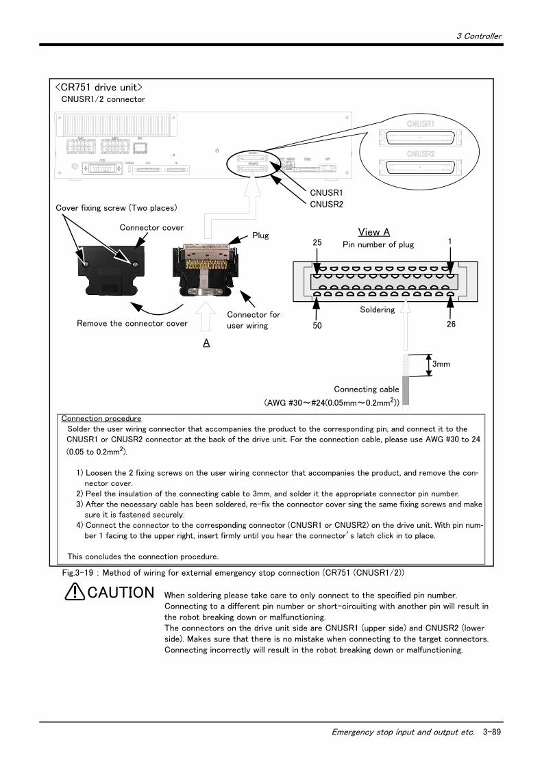
3 Controller
Emergency stop input and output etc. 3-89
Fig.3-19 : Method of wiring for external emergency stop connection (CR751 (CNUSR1/2))
When soldering please take care to only connect to the specified pin number. Connecting to a different pin number or short-circuiting with another pin will result in the robot breaking down or malfunctioning.The connectors on the drive unit side are CNUSR1 (upper side) and CNUSR2 (lower side). Makes sure that there is no mistake when connecting to the target connectors. Connecting incorrectly will result in the robot breaking down or malfunctioning.
<CR751 drive unit>CNUSR1/2 connector
CNUSR1
CNUSR2
3mm
A
View APlugConnector cover
Connecting cable
(AWG #30~#24(0.05mm~0.2mm2))
Connection procedureSolder the user wiring connector that accompanies the product to the corresponding pin, and connect it to the CNUSR1 or CNUSR2 connector at the back of the drive unit. For the connection cable, please use AWG #30 to 24
(0.05 to 0.2mm2).
1) Loosen the 2 fixing screws on the user wiring connector that accompanies the product, and remove the con-nector cover.
2) Peel the insulation of the connecting cable to 3mm, and solder it the appropriate connector pin number.3) After the necessary cable has been soldered, re-fix the connector cover sing the same fixing screws and make
sure it is fastened securely.4) Connect the connector to the corresponding connector (CNUSR1 or CNUSR2) on the drive unit. With pin num-
ber 1 facing to the upper right, insert firmly until you hear the connector’s latch click in to place.
This concludes the connection procedure.
Cover fixing screw (Two places)
Remove the connector cover
Pin number of plug25 1
50 26
SolderingConnector for user wiring
CAUTION
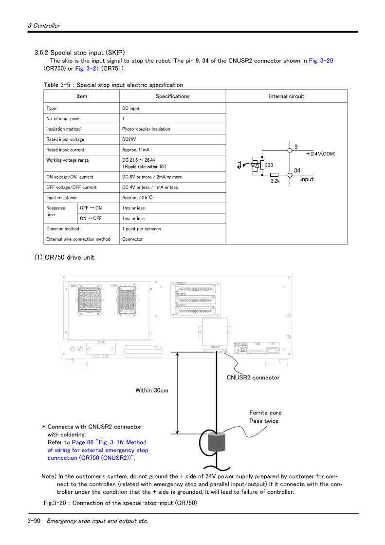
3-90 Emergency stop input and output etc.
3 Controller
3.6.2 Special stop input (SKIP)The skip is the input signal to stop the robot. The pin 9, 34 of the CNUSR2 connector shown in Fig. 3-20
(CR750) or Fig. 3-21 (CR751).
Table 3-5 : Special stop input electric specification
(1) CR750 drive unit
Fig.3-20 : Connection of the special-stop-input (CR750)
Item Specifications Internal circuit
Type DC input
No. of input point 1
Insulation method Photo-coupler insulation
Rated input voltage DC24V
Rated input current Approx. 11mA
Working voltage range DC 21.6 ~ 26.4V
(Ripple rate within 5%)
ON voltage/ON current DC 8V or more / 2mA or more
OFF voltage/OFF current DC 4V or less / 1mA or less
Input resistance Approx. 2.2 k Ω
Response
time
OFF → ON 1ms or less
ON → OFF 1ms or less
Common method 1 point per common
External wire connection method Connector
330
2.2k 入力
+24V(COM)
1A
1B
Input
9
34
CNUSR2
フェライトコア2回通し
30cm以内
* Connects with CNUSR2 connector with soldering. Refer to Page 86 "Fig. 3-16: Method of wiring for external emergency stop connection (CR750 (CNUSR2))".
Within 30cm
CNUSR2 connector
Ferrite core
Pass twice
Note) In the customer's system, do not ground the + side of 24V power supply prepared by customer for con-nect to the controller. (related with emergency stop and parallel input/output) If it connects with the con-troller under the condition that the + side is grounded, it will lead to failure of controller.

3 Controller
Emergency stop input and output etc. 3-91
(2) CR751 drive unit
Fig.3-21 : Connection of the special-stop-input (CR751)
30cm以内
フェライトコア2回通し
CNUSR2コネクタ
* Connects with CNUSR2 connector with soldering. Refer to Page 89 "Fig. 3-19: Method of wiring for external emergency stop connection (CR751 (CNUSR1/2))".
Within 30cmCNUSR2 connector
Ferrite core
Pass twice
Note) In the customer's system, do not ground the + side of 24V power supply prepared by customer for con-nect to the controller. (related with emergency stop and parallel input/output) If it connects with the con-troller under the condition that the + side is grounded, it will lead to failure of controller.
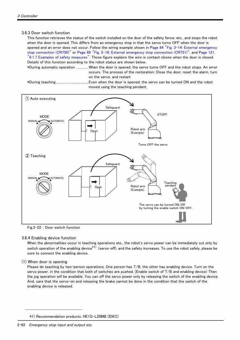
3-92 Emergency stop input and output etc.
3 Controller
3.6.3 Door switch functionThis function retrieves the status of the switch installed on the door of the safety fence, etc., and stops the robot when the door is opened. This differs from an emergency stop in that the servo turns OFF when the door is opened and an error does not occur. Follow the wiring example shown in Page 84 "Fig. 3-14: External emergency stop connection (CR750)" or Page 88 "Fig. 3-18: External emergency stop connection (CR751)", and Page 121, "6.1.7 Examples of safety measures". Those figure explains the wire is contact closes when the door is closed. Details of this function according to the robot status are shown below.
*During automatic operation ...............When the door is opened, the servo turns OFF and the robot stops. An error occurs. The process of the restoration: Close the door, reset the alarm, turn on the servo, and restart
*During teaching........................................Even when the door is opened, the servo can be turned ON and the robot moved using the teaching pendant.
Fig.3-22 : Door switch function
3.6.4 Enabling device functionWhen the abnormalities occur in teaching operations etc., the robot's servo power can be immediately cut only by
switch operation of the enabling device*1) (servo-off), and the safety increases. To use the robot safely, please be sure to connect the enabling device.
(1) When door is openingPlease do teaching by two-person operations. One person has T/B, the other has enabling device. Turn on the servo power, in the condition that both of switches are pushed. (Enable switch of T/B and enabling device) Then the jog operation will be available. You can off the servo power only by releasing the switch of the enabling device.And, care that the servo-on and releasing the brake cannot be done in the condition that the switch of the enabling device is released.
*1) Recommendation products: HE1G-L20MB (IDEC)
Safeguard
Turns OFF the servo
STOP!!
Open
TEACH
AUTO (Ext.)
AUTO (Op.)
Open
TEACH
AUTO (Ext.)
AUTO (Op.)
The servo can be turned ON/Off by turning the enable switch ON/OFF.
Safeguard
Teaching pendant
Robot arm (Example)
Robot arm (Example)
MODEMANUAL AUTOMATIC
① Auto executing
② Teaching
MODEMANUAL AUTOMATIC
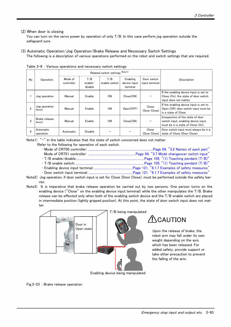
3 Controller
Emergency stop input and output etc. 3-93
(2) When door is closingYou can turn on the servo power by operation of only T/B. In this case perform jog operation outside the safeguard sure.
(3) Automatic Operation/Jog Operation/Brake Release and Necessary Switch SettingsThe following is a description of various operations performed on the robot and switch settings that are required.
Table 3-6 : Various operations and necessary switch settings
Fig.3-23 : Brake release operation
No Operation
Related switch settings Note1)
Note1) "-" in the table indicates that the state of switch concerned does not matter.Refer to the following for operation of each switch.
・ Mode of CR750 controller: ..................................................................................Page 64, "3.2 Names of each part"Mode of CR751 controller: ............................................................Page 94, "3.7 Mode changeover switch input"
・ T/B enable/disable:......................................................................................Page 105, "(1) Teaching pendant (T/B)"・ T/B enable switch: .......................................................................................Page 105, "(1) Teaching pendant (T/B)"・ Enabling device input terminal: .................................................Page 121, "6.1.7 Examples of safety measures"・ Door switch input terminal: ........................................................Page 121, "6.1.7 Examples of safety measures"
DescriptionMode of
controller
T/B
enable/
disable
T/B
enable switch
Enabling
device input
terminal
Door switch
input terminal
1 Jog operation Manual Enable ON Close(ON) -
If the enabling device input is set to
Close (On), the state of door switch input does not matter.
2Jog operation Note2)
Note2) Jog operation, if door switch input is set for Close (Door Close), must be performed outside the safety bar-rier.
Manual Enable ON Open(OFF)Close
(Door Close)
If the enabling device input is set to
Open (Off), door switch input must be in a state of Close
3Brake release Note3)
Note3) It is imperative that brake release operation be carried out by two persons. One person turns on theenabling device ("Close" on the enabling device input terminal) while the other manipulates the T/B. Brakerelease can be effected only when both of the enabling switch device and the T/B enable switch are placedin intermediate position (lightly gripped position). At this point, the state of door switch input does not mat-ter.
Manual Enable ON Close(ON) -
Irrespective of the state of door
switch input, enabling device input must be in a state of Close (On).
4Automatic
operationAutomatic Disable - -
Close
(Door Close)
Door switch input must always be in a
state of Close (Door Close).
Door in Open state
Upon the release of brake, the robot arm may fall under its own weight depending on the axis which has been released. For added safety, provide support or take other precaution to prevent the falling of the arm.
CAUTION
T/B being manipulated
Enabling device being manipulated
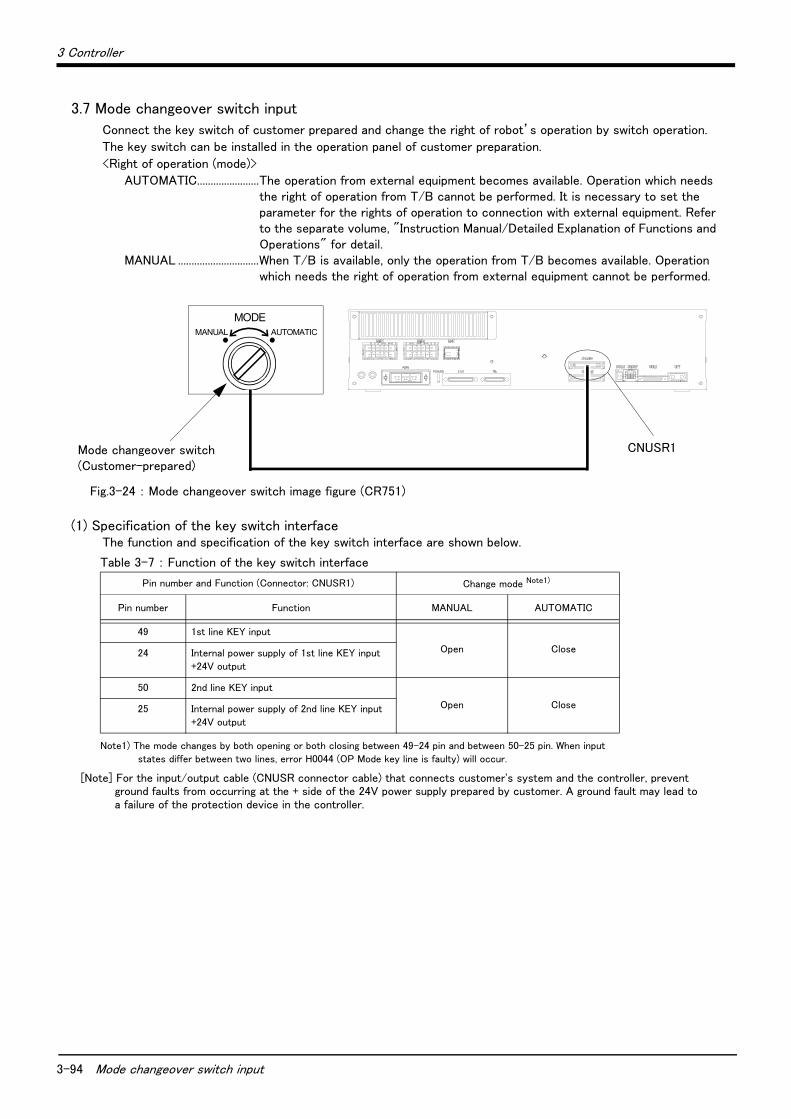
3-94 Mode changeover switch input
3 Controller
3.7 Mode changeover switch input
Connect the key switch of customer prepared and change the right of robot’s operation by switch operation.
The key switch can be installed in the operation panel of customer preparation.
<Right of operation (mode)>
AUTOMATIC.......................The operation from external equipment becomes available. Operation which needs the right of operation from T/B cannot be performed. It is necessary to set the parameter for the rights of operation to connection with external equipment. Refer to the separate volume, "Instruction Manual/Detailed Explanation of Functions and Operations" for detail.
MANUAL ..............................When T/B is available, only the operation from T/B becomes available. Operation which needs the right of operation from external equipment cannot be performed.
Fig.3-24 : Mode changeover switch image figure (CR751)
(1) Specification of the key switch interfaceThe function and specification of the key switch interface are shown below.
MODEMANUAL AUTOMATIC
Mode changeover switch(Customer-prepared)
CNUSR1
Table 3-7 : Function of the key switch interface
Pin number and Function (Connector: CNUSR1) Change mode Note1)
Note1) The mode changes by both opening or both closing between 49-24 pin and between 50-25 pin. When input states differ between two lines, error H0044 (OP Mode key line is faulty) will occur.
Pin number Function MANUAL AUTOMATIC
49 1st line KEY input
Open Close24 Internal power supply of 1st line KEY input+24V output
50 2nd line KEY input
Open Close25 Internal power supply of 2nd line KEY input
+24V output
[Note] For the input/output cable (CNUSR connector cable) that connects customer's system and the controller, prevent ground faults from occurring at the + side of the 24V power supply prepared by customer. A ground fault may lead to a failure of the protection device in the controller.
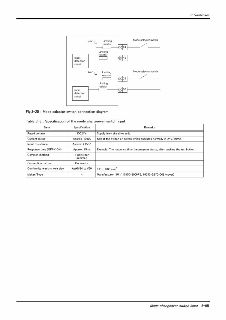
3 Controller
Mode changeover switch input 3-95
Fig.3-25 : Mode selector switch connection diagram
Table 3-8 : Specification of the mode changeover switch input
Item Specification Remarks
Rated voltage DC24V Supply from the drive unit.
Current rating Approx. 10mA Select the switch or button which operates normally in 24V/10mA.
Input resistance Approx. 2.2kΩ
Response time (OFF->ON) Approx. 15ms Example: The response time the program starts, after pushing the run button.
Common method 1 point per common
Connection method Connector
Conformity electric wire size AWG#24 to #30 0.2 to 0.05 mm2
Maker/Type - Manufacturer: 3M / 10150-3000PE, 10350-52Y0-008 (cover)
+24V
24
49
25
50
+24V
Input detection circuit
Input detection circuit
Limiting resistor
Limiting resistor
Mode selector switch
Mode selector switch
Limiting resistor
Limiting resistor
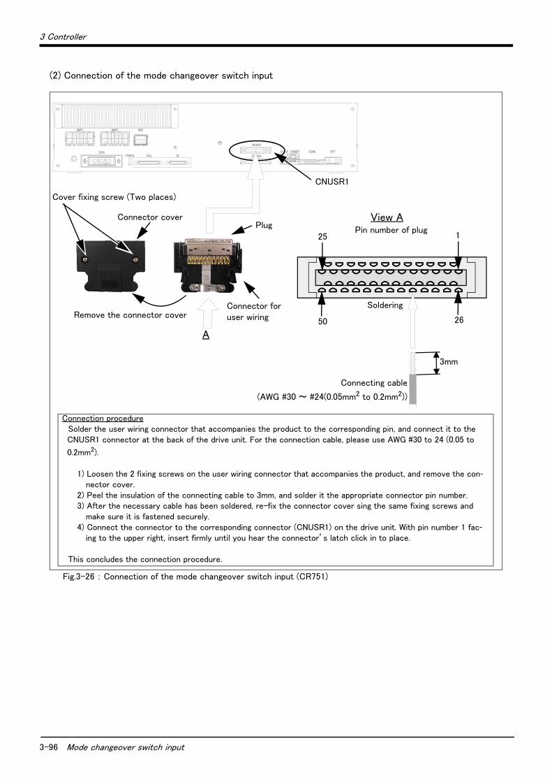
3-96 Mode changeover switch input
3 Controller
(2) Connection of the mode changeover switch input
Fig.3-26 : Connection of the mode changeover switch input (CR751)
CNUSR1
3mm
Connection procedureSolder the user wiring connector that accompanies the product to the corresponding pin, and connect it to the CNUSR1 connector at the back of the drive unit. For the connection cable, please use AWG #30 to 24 (0.05 to
0.2mm2).
1) Loosen the 2 fixing screws on the user wiring connector that accompanies the product, and remove the con-nector cover.
2) Peel the insulation of the connecting cable to 3mm, and solder it the appropriate connector pin number.3) After the necessary cable has been soldered, re-fix the connector cover sing the same fixing screws and
make sure it is fastened securely.4) Connect the connector to the corresponding connector (CNUSR1) on the drive unit. With pin number 1 fac-
ing to the upper right, insert firmly until you hear the connector’s latch click in to place.
This concludes the connection procedure.
25 1
50 26
A
PlugConnector cover
Cover fixing screw (Two places)
Remove the connector coverConnector for user wiring
View APin number of plug
Connecting cable
(AWG #30 ~ #24(0.05mm2 to 0.2mm2))
Soldering
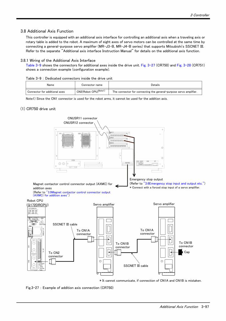
3 Controller
Additional Axis Function 3-97
3.8 Additional Axis Function
This controller is equipped with an additional axis interface for controlling an additional axis when a traveling axis or rotary table is added to the robot. A maximum of eight axes of servo motors can be controlled at the same time by connecting a general-purpose servo amplifier (MR-J3-B, MR-J4-B series) that supports Mitsubishi's SSCNET III. Refer to the separate "Additional axis interface Instruction Manual" for details on the additional axis function.
3.8.1 Wiring of the Additional Axis InterfaceTable 3-9 shows the connectors for additional axes inside the drive unit. Fig. 3-27 (CR750) and Fig. 3-28 (CR751) shows a connection example (configuration example).
Table 3-9 : Dedicated connectors inside the drive unit
(1) CR750 drive unit
Fig.3-27 : Example of addition axis connection (CR750)
Name Connector name Details
Connector for additional axes CN2(Robot CPU)Note1)
Note1) Since the CN1 connector is used for the robot arms, it cannot be used for the addition axis.
The connector for connecting the general-purpose servo amplifier.
サーボアンプ
※CN1A、CN1Bの接続を間違えると、通信できません。
キャップ
サーボアンプ
CN1Aコネクタへ
CN1Bコネクタへ
SSCNETⅢケーブル
CN1Bコネクタへ
CNUSR11コネクタ
CNUSR12コネクタ
CN2コネクタへ
CN1Aコネクタへ
SSCNETⅢケーブル
ロボットCPU(Q172DRCPU)
8
4
0
C
0
8
C
4
BATFRONT
CN
2C
N1
EMICAUTION
STOP RUN1 2
SW
Q172DRCPU
ACFAILRIO
MPG
TU
I/F
DIS
PLA
Y I
/F
Servo amplifier
Cap
* It cannot communicate, if connection of CN1A and CN1B is mistaken.
CNUSR11 connector
CNUSR12 connector
To CN1B connector
Servo amplifier
SSCNET III cable
To CN1A connector
To CN1B connector
Robot CPU
To CN1A connector
To CN2 connector
SSCNET III cable
Emergency stop output(Refer to "3.6Emergency stop input and output etc.")* Connect with a forced stop input of a servo amplifier.
Magnet contactor control connector output (AXMC) for addition axes(Refer to "3.9Magnet contactor control connector output (AXMC) for addition axes")
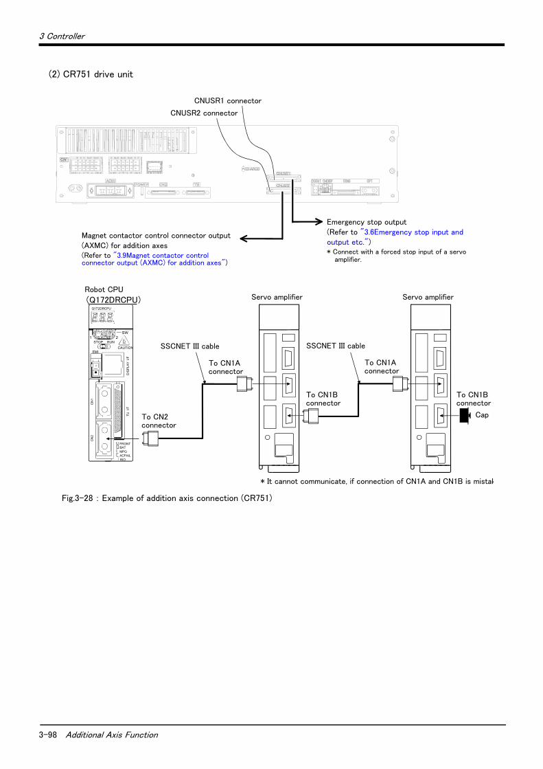
3-98 Additional Axis Function
3 Controller
(2) CR751 drive unit
Fig.3-28 : Example of addition axis connection (CR751)
CN2コネクタへ
サーボアンプ
※CN1A、CN1Bの接続を間違えると、通信できません
キャップ
CN1Aコネクタへ CN1Aコネクタへ
CN1Bコネクタへ
SSCNETⅢケーブル SSCNETⅢケーブル
CN1Bコネクタ
ロボットCPU(Q172DRCPU)
8
4
0
C
0
8
C
4
BATFRONT
CN
2C
N1
EMICAUTION
STOP RUN1 2
SW
Q172DRCPU
ACFAILRIO
MPG
TU
I/F
DIS
PLA
Y I
/F
サーボアンプ
CNUSR1コネクタ
CNUSR2コネクタ
Servo amplifier
SSCNET III cable
Robot CPU
To CN1B connector
Cap
* It cannot communicate, if connection of CN1A and CN1B is mistak
To CN1A connector
To CN1A connector
To CN2 connector
SSCNET III cable
To CN1B connector
Servo amplifier
CNUSR1 connector
CNUSR2 connector
Emergency stop output(Refer to "3.6Emergency stop input and output etc.")* Connect with a forced stop input of a servo
amplifier.
Magnet contactor control connector output (AXMC) for addition axes(Refer to "3.9Magnet contactor control connector output (AXMC) for addition axes")

3 Controller
Additional Axis Function 3-99
(3) Example of the installation of the noise filter1) EMC filter (recommended)
Please install the recommendation filter shown below according to the example of connection.
Fig.3-29 : Example of EMC noise filter installation
1)
2)
Note1) For 1-phase 200V to 230VAC power supply, connect the power supply to L1, L2 and leave L3 open. There is no L3 for 1-phase 100 to 120 VAC power supply.
Note2) The example is when a surge protector is connected.
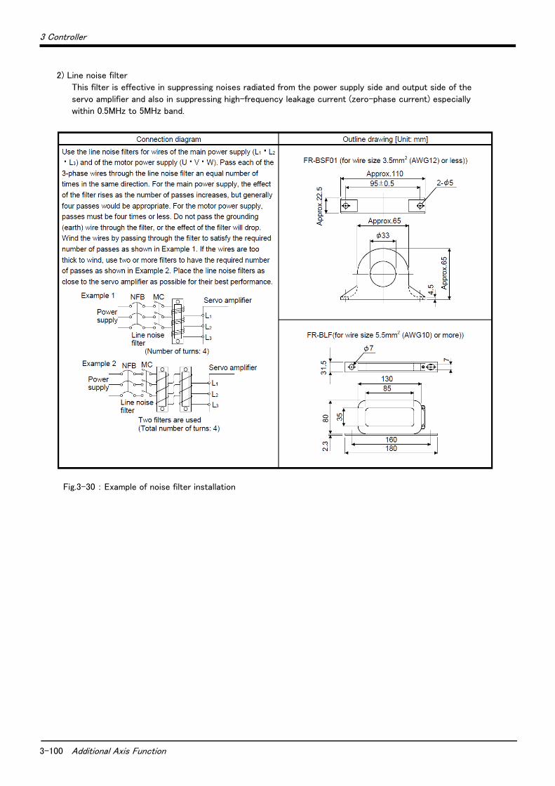
3-100 Additional Axis Function
3 Controller
2) Line noise filter
This filter is effective in suppressing noises radiated from the power supply side and output side of the
servo amplifier and also in suppressing high-frequency leakage current (zero-phase current) especially
within 0.5MHz to 5MHz band.
Fig.3-30 : Example of noise filter installation
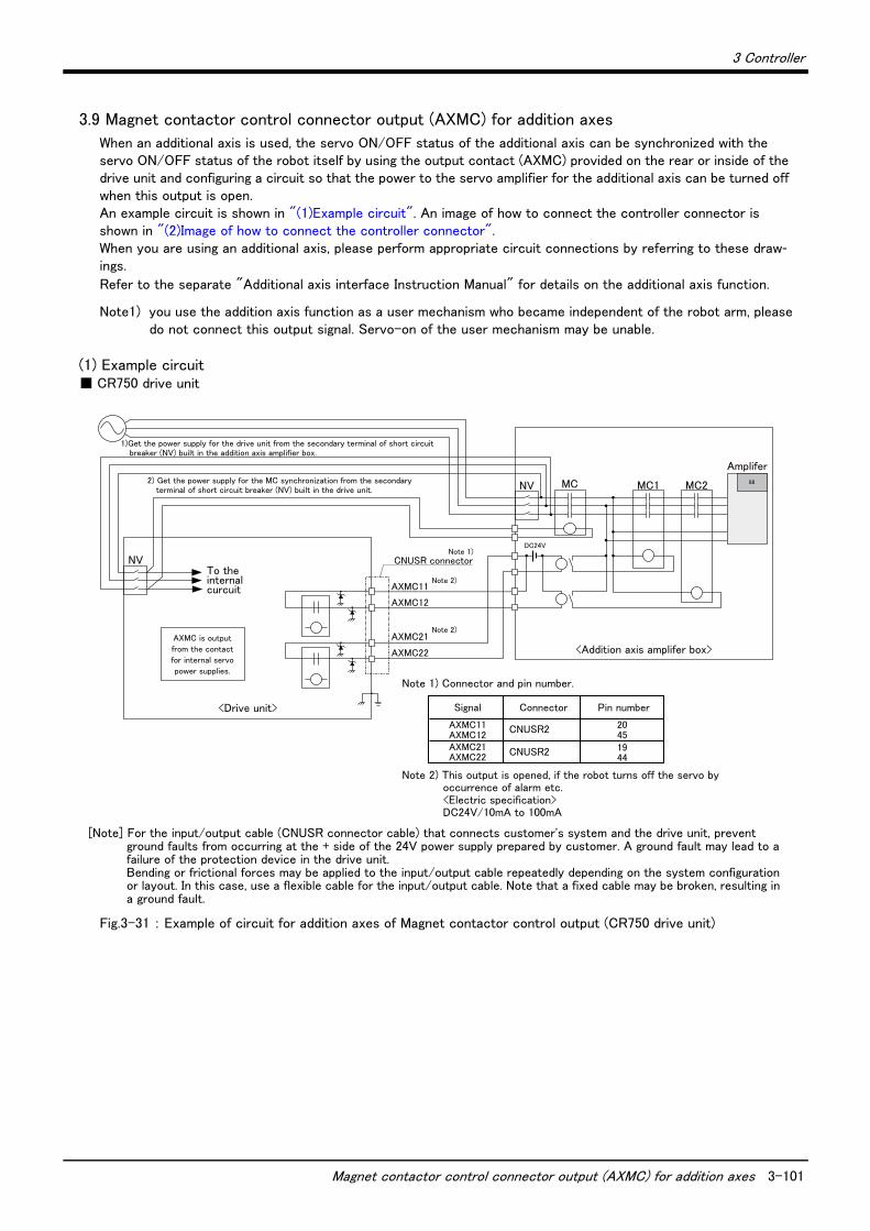
3 Controller
Magnet contactor control connector output (AXMC) for addition axes 3-101
3.9 Magnet contactor control connector output (AXMC) for addition axes
When an additional axis is used, the servo ON/OFF status of the additional axis can be synchronized with the servo ON/OFF status of the robot itself by using the output contact (AXMC) provided on the rear or inside of the drive unit and configuring a circuit so that the power to the servo amplifier for the additional axis can be turned off when this output is open. An example circuit is shown in "(1)Example circuit". An image of how to connect the controller connector is shown in "(2)Image of how to connect the controller connector".When you are using an additional axis, please perform appropriate circuit connections by referring to these draw-ings.
Refer to the separate "Additional axis interface Instruction Manual" for details on the additional axis function.
Note1) you use the addition axis function as a user mechanism who became independent of the robot arm, pleasedo not connect this output signal. Servo-on of the user mechanism may be unable.
(1) Example circuit■ CR750 drive unit
Fig.3-31 : Example of circuit for addition axes of Magnet contactor control output (CR750 drive unit)
[Note] For the input/output cable (CNUSR connector cable) that connects customer's system and the drive unit, prevent ground faults from occurring at the + side of the 24V power supply prepared by customer. A ground fault may lead to a failure of the protection device in the drive unit. Bending or frictional forces may be applied to the input/output cable repeatedly depending on the system configuration or layout. In this case, use a flexible cable for the input/output cable. Note that a fixed cable may be broken, resulting in a ground fault.
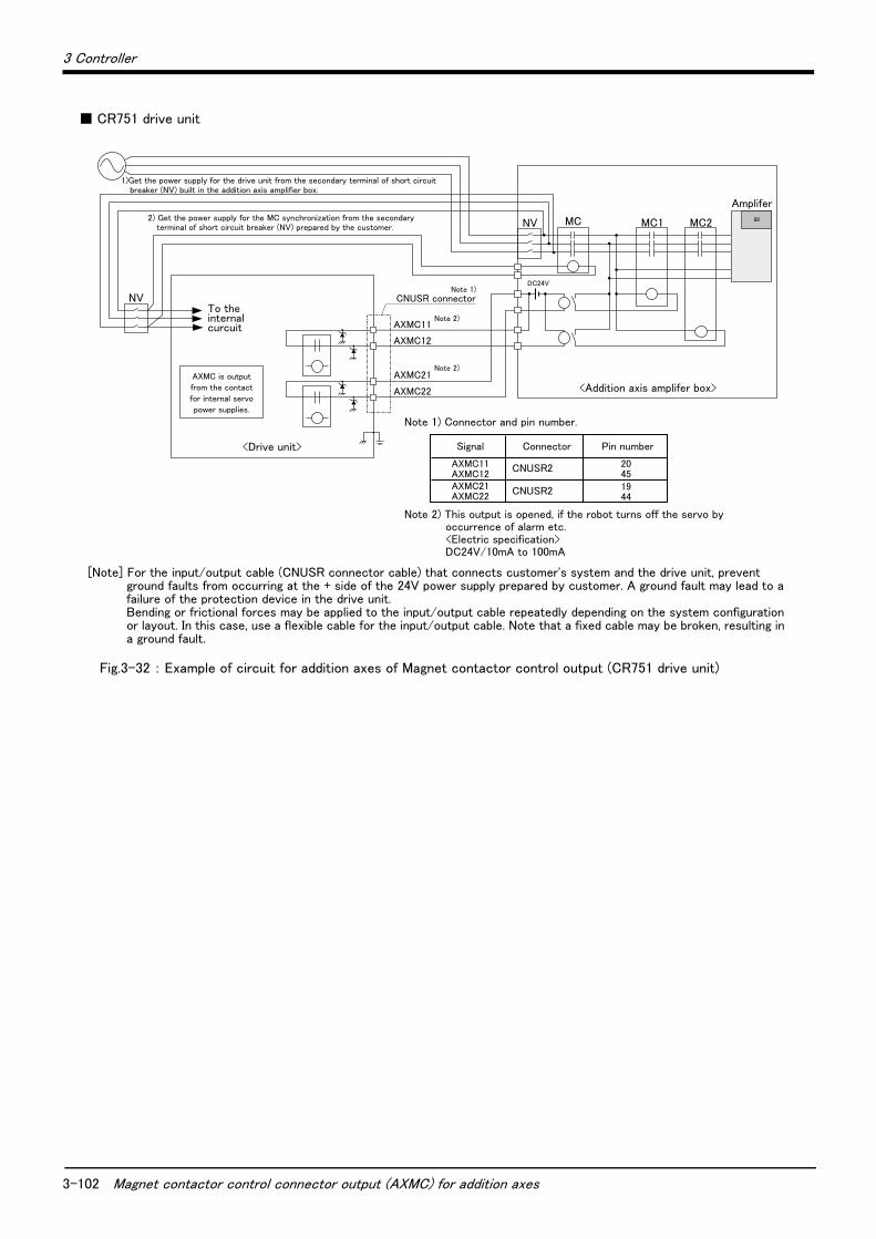
3-102 Magnet contactor control connector output (AXMC) for addition axes
3 Controller
■ CR751 drive unit
Fig.3-32 : Example of circuit for addition axes of Magnet contactor control output (CR751 drive unit)
[Note] For the input/output cable (CNUSR connector cable) that connects customer's system and the drive unit, prevent ground faults from occurring at the + side of the 24V power supply prepared by customer. A ground fault may lead to a failure of the protection device in the drive unit. Bending or frictional forces may be applied to the input/output cable repeatedly depending on the system configuration or layout. In this case, use a flexible cable for the input/output cable. Note that a fixed cable may be broken, resulting in a ground fault.
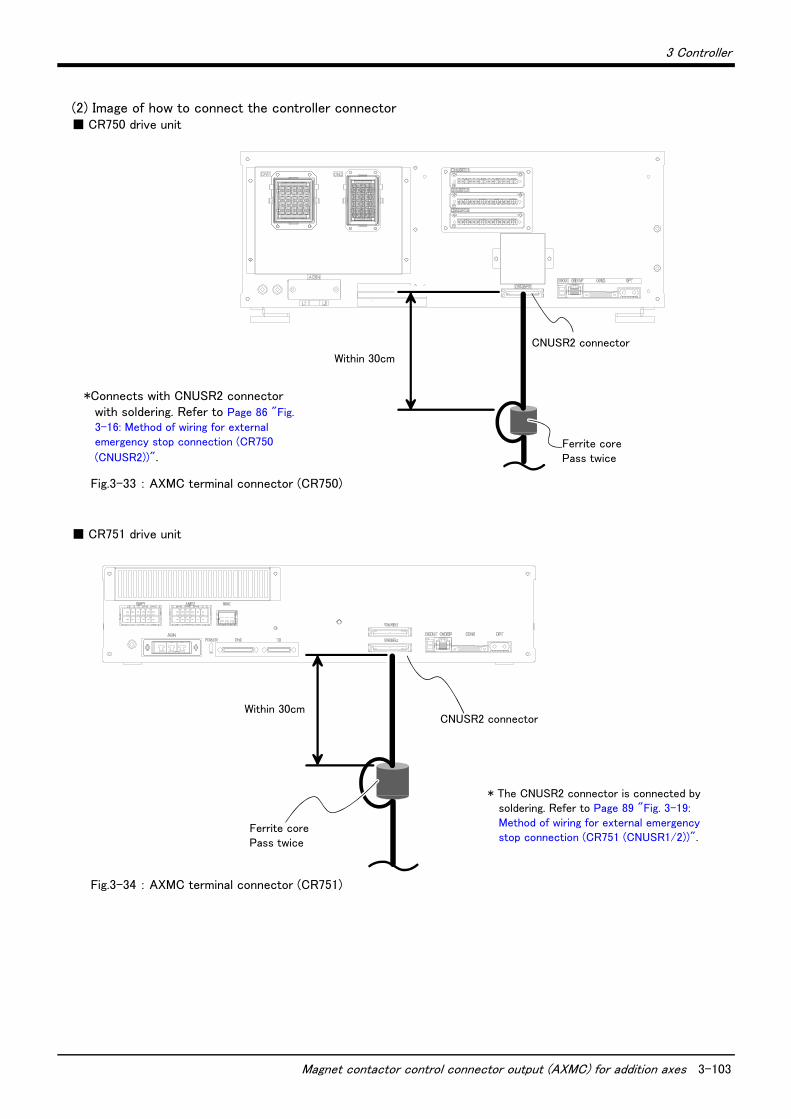
3 Controller
Magnet contactor control connector output (AXMC) for addition axes 3-103
(2) Image of how to connect the controller connector■ CR750 drive unit
Fig.3-33 : AXMC terminal connector (CR750)
■ CR751 drive unit
Fig.3-34 : AXMC terminal connector (CR751)
30cm以内
フェライトコア2回通し
CNUSR2コネクタ
*Connects with CNUSR2 connector with soldering. Refer to Page 86 "Fig. 3-16: Method of wiring for external emergency stop connection (CR750
(CNUSR2))".
Within 30cm
Ferrite corePass twice
CNUSR2 connector
30cm以内
フェライトコア2回通し
CNUSR2コネクタ
* The CNUSR2 connector is connected by soldering. Refer to Page 89 "Fig. 3-19: Method of wiring for external emergency stop connection (CR751 (CNUSR1/2))".
Within 30cm
Ferrite corePass twice
CNUSR2 connector

3-104
3 Controller
3.10 Options
■ What are options?There are a variety of options for the robot designed to make the setting up process easier for user needs.
User installation is required for the options. Options come in two types: "set options" and "single options".
1. Set options ......................................A combination of single options and parts that together, form a set for servingsome purpose.
2. Single options .................................That are configured from the fewest number of required units of a part.Please choose user's purpose additionally.
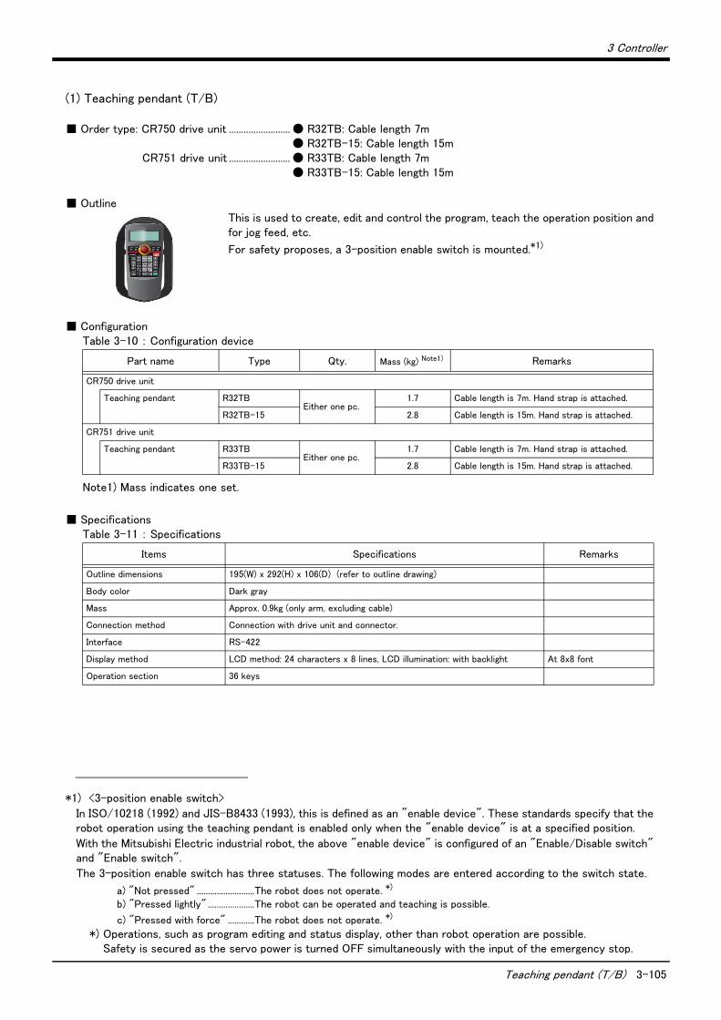
3 Controller
Teaching pendant (T/B) 3-105
(1) Teaching pendant (T/B)
■ Order type: CR750 drive unit ......................... ● R32TB: Cable length 7m● R32TB-15: Cable length 15m
CR751 drive unit ......................... ● R33TB: Cable length 7m● R33TB-15: Cable length 15m
■ OutlineThis is used to create, edit and control the program, teach the operation position and for jog feed, etc.
For safety proposes, a 3-position enable switch is mounted.*1)
■ ConfigurationTable 3-10 : Configuration device
■ SpecificationsTable 3-11 : Specifications
*1) <3-position enable switch>
In ISO/10218 (1992) and JIS-B8433 (1993), this is defined as an "enable device". These standards specify that the robot operation using the teaching pendant is enabled only when the "enable device" is at a specified position.
With the Mitsubishi Electric industrial robot, the above "enable device" is configured of an "Enable/Disable switch" and "Enable switch".
The 3-position enable switch has three statuses. The following modes are entered according to the switch state.
a) "Not pressed" ..........................The robot does not operate. *)
b) "Pressed lightly" .....................The robot can be operated and teaching is possible.
c) "Pressed with force" ............The robot does not operate. *)
*) Operations, such as program editing and status display, other than robot operation are possible.Safety is secured as the servo power is turned OFF simultaneously with the input of the emergency stop.
Part name Type Qty. Mass (kg) Note1)
Note1) Mass indicates one set.
Remarks
CR750 drive unit
Teaching pendant R32TBEither one pc.
1.7 Cable length is 7m. Hand strap is attached.
R32TB-15 2.8 Cable length is 15m. Hand strap is attached.
CR751 drive unit
Teaching pendant R33TBEither one pc.
1.7 Cable length is 7m. Hand strap is attached.
R33TB-15 2.8 Cable length is 15m. Hand strap is attached.
Items Specifications Remarks
Outline dimensions 195(W) x 292(H) x 106(D) (refer to outline drawing)
Body color Dark gray
Mass Approx. 0.9kg (only arm, excluding cable)
Connection method Connection with drive unit and connector.
Interface RS-422
Display method LCD method: 24 characters x 8 lines, LCD illumination: with backlight At 8x8 font
Operation section 36 keys
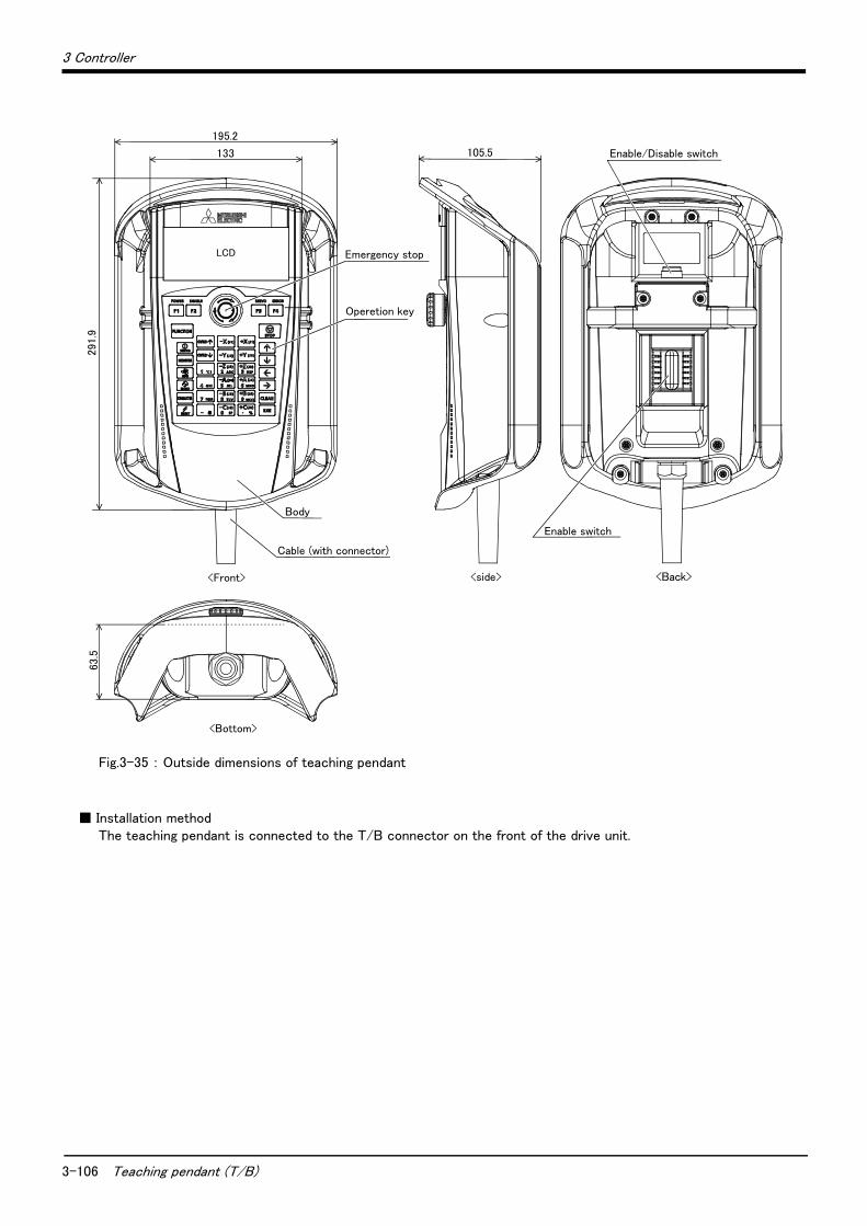
3-106 Teaching pendant (T/B)
3 Controller
Fig.3-35 : Outside dimensions of teaching pendant
■ Installation methodThe teaching pendant is connected to the T/B connector on the front of the drive unit.
Enable/Disable switch
Emergency stop
Enable switch
Operetion key
Body
Cable (with connector)
<Back>
<Bottom>
63.5
<Front>
LCD
291.9
195.2
133
<side>
105.5
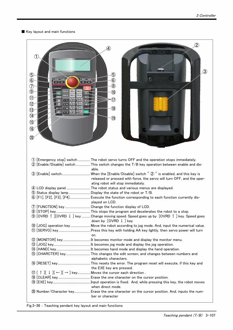
3 Controller
Teaching pendant (T/B) 3-107
■ Key layout and main functions
Fig.3-36 : Teaching pendant key layout and main functions
⑪
⑭⑬
⑫
⑨
⑤⑥⑦
⑮
⑯
⑳
⑤⑥⑧
⑱
⑲
⑩
⑰
①
④
③
②
① [Emergency stop] switch ................ The robot servo turns OFF and the operation stops immediately.② [Enable/Disable] switch .................. This switch changes the T/B key operation between enable and dis-
able.③ [Enable] switch.................................... When the [Enable/Disable] switch " ② " is enabled, and this key is
released or pressed with force, the servo will turn OFF, and the oper-ating robot will stop immediately.
④ LCD display panel .............................. The robot status and various menus are displayed.⑤ Status display lamp ........................... Display the state of the robot or T/B.⑥ [F1], [F2], [F3], [F4].......................... Execute the function corresponding to each function currently dis-
played on LCD. ⑦ [FUNCTION] key ................................ Change the function display of LCD. ⑧ [STOP] key........................................... This stops the program and decelerates the robot to a stop.⑨ [OVRD ↑ ][OVRD ↓ ] key ........... Change moving speed. Speed goes up by [OVRD ↑ ] key. Speed goes
down by [OVRD ↓ ] key⑩ [JOG] operation key......................... Move the robot according to jog mode. And, input the numerical value. ⑪ [SERVO] key........................................ Press this key with holding AA key lightly, then servo power will turn
on. ⑫ [MONITOR] key .................................. It becomes monitor mode and display the monitor menu.⑬ [JOG] key.............................................. It becomes jog mode and display the jog operation. ⑭ [HAND] key........................................... It becomes hand mode and display the hand operation.⑮ [CHARCTER] key............................... This changes the edit screen, and changes between numbers and
alphabetic characters.⑯ [RESET] key......................................... This resets the error. The program reset will execute, if this key and
the EXE key are pressed. ⑰ [ ↑ ][ ↓ ][ ← ][ → ] key................ Moves the cursor each direction .⑱ [CLEAR] key ........................................ Erase the one character on the cursor position.⑲ [EXE] key............................................... Input operation is fixed. And, while pressing this key, the robot moves
when direct mode.⑳ Number/Character key.................... Erase the one character on the cursor position. And, inputs the num-
ber or character
3-108 MELSOFT RT ToolBox2/RT ToolBox2 mini
3 Controller
(2) MELSOFT RT ToolBox2/RT ToolBox2 mini
■ Order type : ● MELSOFT RT ToolBox2*For windows CD-ROM : 3D-11C-WINE
● MELSOFT RT ToolBox2 mini*For windows CD-ROM : 3D-12C-WINE
■ OutlineThis is handy software that fully uses the personal computer functions. It can be used in various stages from the robot specifications study (tact study, etc.) to the design support (creation and editing of programs), start up support (execution, control and debugging of program), and maintenance.
The "personal computer support software" which supports these function fully, and the "personal computer support software mini" which does not have the simulation function are available.
■ ConfigurationTable 3-12 : Product configuration
■ Features(1) Simple operation with guidance method and menu method
The Windows standard is used for windows operation, so the controller initialization and startup operations can be carried out easily by following the instructions given on the screen. Even a beginner can easily carry out the series of operations from program creation to execution.
(2) Increased work efficiency with ample support functionsThe work efficiency is greatly improved with the multi-window method that carries out multiple steps and dis-plays in parallel. The renumbering function, and copy, search, syntax check and step execution are especially sufficient, and are extremely useful when editing or debugging the program.With the simulation function support, the program can be debugged and the tact checked before starting the machine at the site. This allows the on-site startup work efficiently to be greatly improved.
(3) The maintenance forecast function increases the efficiency of maintenance work. Analyze the load condition while the robot is actually operating. Based on this analysis, calculate the time for maintenance, such as lubri-cation and belt replacement. By utilizing this information, the line stop time as well as the maintenance costs can be reduced.
(4) The position recovery support function increases the recovery efficiency in the event of origin position dis-placement. This function compensates the origin settings and position data by just reproducing several previ-ous teaching points when hand and/or arm displacement occurs, when replacing the motor and the belts, or when reloading the robot. This function can reduce the time required for recovery.
Part name Type Medium Mass (kg) Note1)
Note1) Mass indicates one set.
Remarks
RT ToolBox2 3D-11C-WINE CD-ROM 0.2
RT ToolBox2 mini 3D-12C-WINE CD-ROM 0.2
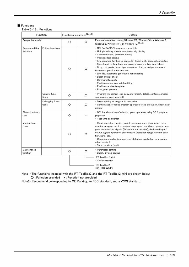
3 Controller
MELSOFT RT ToolBox2/RT ToolBox2 mini 3-109
■ FunctionsTable 3-13 : Functions
Function Functional existenceNote1)
Note1) The functions included with the RT ToolBox2 and the RT ToolBox2 mini are shown below. ○ : Function provided ×: Function not provided
Details
Compatible model ○ ○
Personal computer running Windows XP, Windows Vista, Windows 7,
Windows 8, Windows 8.1, or Windows 10. Note2)
Note2) Recommend corresponding to CE Marking, an FCC standard, and a VCCI standard.
Program editing
functions
Editing functions
○ ○
・ MELFA BASIC V language compatible
・ Multiple editing screen simultaneously display・ Command input, comment writing
・ Position data editing・ File operation (writing to controller, floppy disk, personal computer)
・ Search and replace function (using characters, line Nos., labels)
・ Copy, cut, paste, insert (per character, line), undo (per command statement, position conversion)
・ Line No. automatic generation, renumbering・ Batch syntax check
・ Command template
・ Position conversion batch editing・ Position variable template
・ Print, print preview
Control func-tions
○ ○・ Program file control (list, copy, movement, delete, content compari-son, name change, protect)
Debugging func-tions ○ ○
・ Direct editing of program in controller・ Confirmation of robot program operation (step execution, direct exe-cution)
Simulation func-tion ○ ×
・ Off-line simulation of robot program operation using CG (computer
graphics)
・ Tact time calculation
Monitor func-tions
○ ○
・ Robot operation monitor (robot operation state, stop signal, error monitor, program monitor (execution program, variables), general-pur-pose input/output signals (forced output possible), dedicated input/
output signals, operation confirmation (operation range, current posi-tion, hand, etc.)
・ Operation monitor (working time statistics, production information, robot version)
・ Servo monitor (load)
Maintenance
function ○ ○
・ Parameter setting
・ Batch, divided backup
RT ToolBox2 mini
(3D-12C-WINE)
RT ToolBox2
(3D-11C-WINE)
3-110 Instruction Manual (bookbinding)
3 Controller
(3) Instruction Manual (bookbinding)
■ Order type: ● 5F-RA01-PE01 ..............RH-3FH-Q series
■ Outline
This is a printed version of the CD-ROM (instruction manual) supplied with this product.
■ ConfigurationTable 3-14 : Product configuration
Name Type Mass (Kg) Note1)
Note1) Mass indicates one set.
Specifications
Instruction Manual 5F-RA01-PE01 2.6 The instructions manual set of "RH-3FH-Q series".
Safety Manual BFP-A8006 - Items relating to safety in handling the robot
Standard Specifications BFP-A8880 - Specification of the robot arm and controller
Robot Arm Setup & Maintenance BFP-A8865 -Installation method of the robot arm, jog operation, and
maintenance and inspection procedures
Controller Setup, Basic Operation and Maintenance BFP-A8886 -Installation method of the controller, basic operation,
and maintenance and inspection procedures
Detailed Explanation of Functions and Operations BFP-A8869 -Functions of the controller and T/B, operation
method, and explanation of MELFA-BASIC V
Troubleshooting BFP-A8871 - Causes of errors occurred and their countermeasures
Additional axis function BFP-A8663 - Function of the additional axis, operation method.
Tracking Function Manual BFP-A8664 - Function of the Tracking, operation method.
Extended Function BFP-A8787 - Function of the Extended, operation method.
3 Controller
Maintenance parts 3-111
3.11 Maintenance parts
The consumable parts used in the controller are shown in Table 3-15. Purchase these parts from your dealer when required. Some Mitsubishi-designated parts differ from the maker's standard parts. Thus, confirm the part name, robot arm and controller serial No. and purchase the parts from your dealer.
Table 3-15 : Controller consumable parts list
No. Name Type Note1)
Note1) Confirm the robot arm serial No., and contact the dealer or service branch of Mitsubishi Electric Co., for the type.
Qty. Usage place Supplier
1 Lithium battery Q6BAT 1 The battery unit con-nected to the robot CPU
unit
Mitsubishi Electric 2 Filter CR750 drive unit:
BKOFA0773H42
CR751 drive unit: BKOFA0773H41
1 Inside the filter cover

4-112 List of commands
4Software
4 Software
4.1 List of commands
The available new functions in MELFA-BASIC V are given in Table 4-1.
Table 4-1 : List of MELFA-BASIC V commands
Type Class Function Input format (example)
Posi
tion a
nd
ope
ration c
ontr
ol
Joint interpolation Moves to the designated position with joint interpolation. Mov P1
Linear interpolation Moves to the designated position with linear interpolation. Mvs P1
Circular interpolation Moves along a designated arc (start point → passing point → start point
(end point)) with 3-dimensional circular interpolation (360 degrees).Mvc P1,P2,P1
Moves along a designated arc (start point → passing point → end point)
with 3-dimensional circular interpolation.Mvr P1,P2,P3
Moves along the arc on the opposite side of a designated arc (start point
→ reference point → end point) with 3-dimensional circular interpola-tion.
Mvr2 P1,P9,P3
Moves along a set arc (start point → end point) with 3-dimensional cir-cular interpolation.
Mvr3 P1,P9,P3
Speed designation Designates the speed for various interpolation operations with a per-centage (0.1% unit).
Ovrd 100
Designate the speed for joint interpolation operation with a percentage
(0.1% unit).JOvrd 100
Designates the speed for linear and circular interpolation with a numeri-cal value (mm/s unit).
Spd 123.5
Designates the acceleration/deceleration time as a percentage in
respect to the predetermined maximum acceleration/deceleration. (1% unit)
Accel 50,80
Automatically adjusts the acceleration/deceleration according to the parameter setting value.
Oadl ON
Sets the hand and work conditions for automatic adjustment of the
acceleration/deceleration.Loadset 1,1
Operation Adds a process unconditionally to the operation. Wth
Adds a process conditionally to the operation. WthIf
Designates smooth operation. Cnt 1,100,200
Performance of movement is upgraded corresponding to the application. MvTune 4
Designates the positioning completion conditions with a No. of pulses. Fine 200
Designates the positioning completion conditions with a distance in a straight line
Fine 1, P
Designates the positioning completion conditions with a joint interpola-tion.
Fine 0.5, J, 2
Turns the servo power ON/OFF for all axes. Servo OFF
Limits the operation of each axis so that the designated torque is not exceeded.
Torq 4,10
Position control Designates the base conversion data. Base P1
Designates the tool conversion data. Tool P1
Float control The robot arm rigidity is lowered and softened. (XYZ coordinate system) Cmp Pos ,&B00000011
The robot arm rigidity is lowered and softened. (JOINT coordinate sys-tem)
Cmp Jnt ,&B00000011
The robot arm rigidity is lowered and softened. (TOOL coordinate sys-tem)
Cmp Tool ,&B00000011
The robot arm rigidity is returned to the normal state. Cmp Off
The robot arm rigidity is designated. CmpG 1.0,1.0,1.0,1.0,1.0,1.0,1.0,1.0
Pallet Defines the pallet. Def Plt 1,P1,P2,P3,P4,5,3,1
Operates the pallet grid point position. Plt 1,M1
Singular point pas-sage
Move to a specified position using linear interpolation passing through a
singular point.Mvs P1 Type 0,2

4Software
List of commands 4-113
Pro
gram
contr
ol
Branching Branches unconditionally to the designated place. GoTo 120
Branches according to the designated conditions. If M1=1 Then GoTo *L100Else GoTo 20
End If
Repeats until the designated end conditions are satisfied. For M1=1 TO 10
Next M1
Repeats while the designated conditions are satisfied. While M1<10
WEnd
Branches corresponding to the designated expression value. On M1 GoTo *La1, *Lb2, *Lc3
Executes program block corresponding to the designated expression
value..
Select
Case 1
Break
Case 2
BreakEnd Select
Moves the program process to the next line. Skip
Collision detection Set to enable/disable the collision detection. ColChk ON/OFF
Set the detection level of the collision detection. ColLvl 100,80,,,,,,
Subroutine Executes the designated subroutine. (Within program) GoSub *L200
Returns from the subroutine. Return
Executes the designated program. CallP "P10",M1,P1
Defines the program argument executed with the CALLP command. FPrm M10,P10
Executes the subroutine corresponding to the designated expression value.
On M1 GoSub *La1, *Lb2, *Lc3
Interrupt Defines the interrupt conditions and process. Def Act 1, M1=1 GoTo *L100
Enables/disables the interrupt. Act 1=1
Defines the start line of the program to be executed when an interrupt is
generated from the communication line.On Com(1) GoSub *L100
Enables the interrupt from the communication line. Com(1) On
Disables the interrupt from the communication line. Com(1) Off
Stops the interrupt from the communication line. Com(1) Stop
Wait Designates the wait time, and the output signal pulse output time. (0.01s unit)
Dly 0.5
Waits until the variable becomes the designated value. Wait M_In(1)=1
Stop Stops the program execution. Hlt
Generates an error. During program execution, continue, stop or servo
OFF can be designated.Error 9000
End Ends the program execution. End
Han
d Hand open Opens the designated hand. HOpen 1
Hand close Closes the designated hand. HClose 1
Input/
out
put Assignment Defines the input/output variables. Def IO PORT1=BIT,0
Input Retrieves the general-purpose input signal. M1=M_In(1)
Output Calls out the general-purpose output signal.M_Out(1) =0
Par
alle
l exe
cution
Mechanism designa-tion
Acquires the mechanism with the designated mechanism No. GetM 1
Releases the mechanism with the designated mechanism No. RelM 1
Selection Selects the designated program for the designated slot. XLoad 2,"P102"
Start/stop Carries out parallel execution of the designated program. XRun 3,"100",0
Stops parallel execution of the designated program. XStp 3
Returns the designated program's execution line to the head and enters
the program selection enabled state.XRst 3
Type Class Function Input format (example)
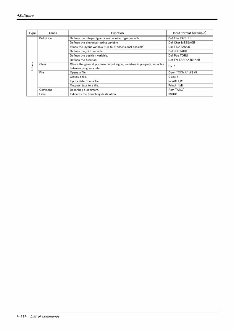
4-114 List of commands
4Software
Oth
ers
Definition Defines the integer type or real number type variable. Def Inte KAISUU
Defines the character string variable. Def Char MESSAGE
efines the layout variable. (Up to 3-dimensional possible) Dim PDATA(2,3)
Defines the joint variable. Def Jnt TAIHI
Defines the position variable. Def Pos TORU
Defines the function. Def FN TASU(A,B)=A+B
Clear Clears the general-purpose output signal, variables in program, variables
between programs, etc.Clr 1
File Opens a file. Open "COM1:" AS #1
Closes a file. Close #1
Inputs data from a file. Input# 1,M1
Outputs data to a file. Print# 1,M1
Comment Describes a comment. Rem "ABC"
Label Indicates the branching destination. *SUB1
Type Class Function Input format (example)
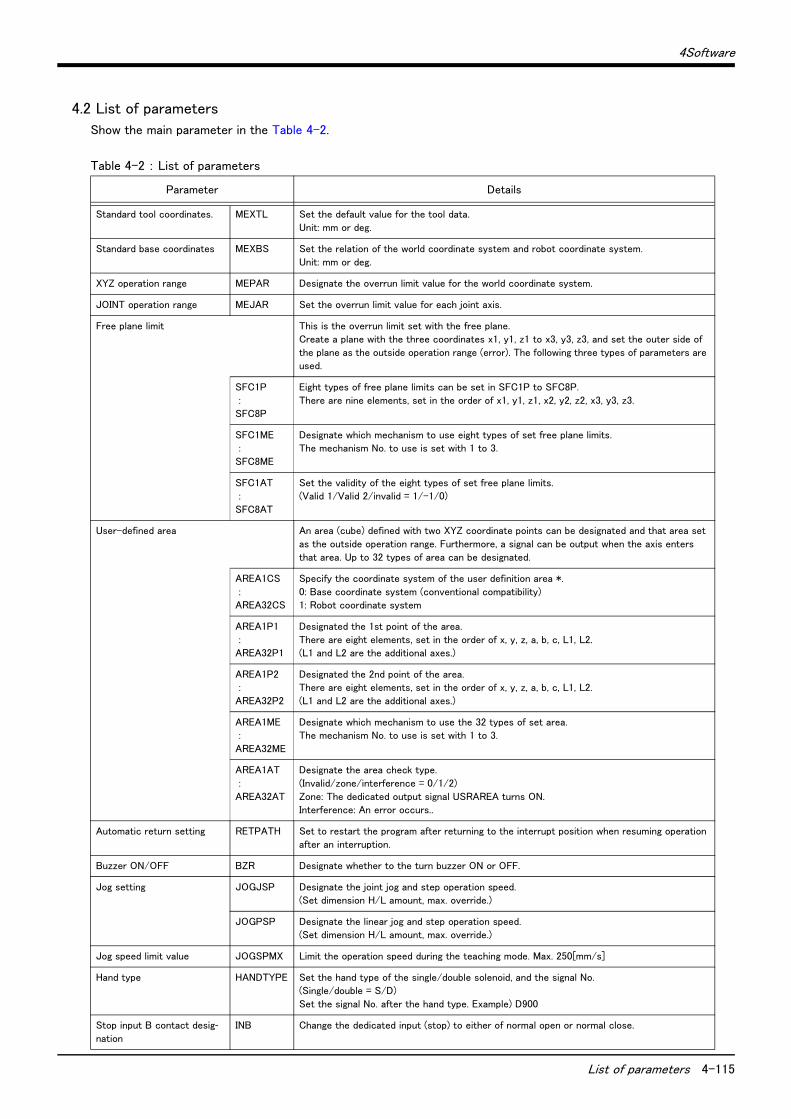
4Software
List of parameters 4-115
4.2 List of parameters
Show the main parameter in the Table 4-2.
Table 4-2 : List of parameters
Parameter Details
Standard tool coordinates. MEXTL Set the default value for the tool data.
Unit: mm or deg.
Standard base coordinates MEXBS Set the relation of the world coordinate system and robot coordinate system.
Unit: mm or deg.
XYZ operation range MEPAR Designate the overrun limit value for the world coordinate system.
JOINT operation range MEJAR Set the overrun limit value for each joint axis.
Free plane limit This is the overrun limit set with the free plane.Create a plane with the three coordinates x1, y1, z1 to x3, y3, z3, and set the outer side of
the plane as the outside operation range (error). The following three types of parameters are used.
SFC1P
:SFC8P
Eight types of free plane limits can be set in SFC1P to SFC8P.
There are nine elements, set in the order of x1, y1, z1, x2, y2, z2, x3, y3, z3.
SFC1ME :
SFC8ME
Designate which mechanism to use eight types of set free plane limits.The mechanism No. to use is set with 1 to 3.
SFC1AT :
SFC8AT
Set the validity of the eight types of set free plane limits.(Valid 1/Valid 2/invalid = 1/-1/0)
User-defined area An area (cube) defined with two XYZ coordinate points can be designated and that area set
as the outside operation range. Furthermore, a signal can be output when the axis enters
that area. Up to 32 types of area can be designated.
AREA1CS
:AREA32CS
Specify the coordinate system of the user definition area *.
0: Base coordinate system (conventional compatibility) 1: Robot coordinate system
AREA1P1
:AREA32P1
Designated the 1st point of the area.
There are eight elements, set in the order of x, y, z, a, b, c, L1, L2.(L1 and L2 are the additional axes.)
AREA1P2 :
AREA32P2
Designated the 2nd point of the area.There are eight elements, set in the order of x, y, z, a, b, c, L1, L2.
(L1 and L2 are the additional axes.)
AREA1ME :
AREA32ME
Designate which mechanism to use the 32 types of set area.The mechanism No. to use is set with 1 to 3.
AREA1AT
:
AREA32AT
Designate the area check type.
(Invalid/zone/interference = 0/1/2)
Zone: The dedicated output signal USRAREA turns ON.Interference: An error occurs..
Automatic return setting RETPATH Set to restart the program after returning to the interrupt position when resuming operation after an interruption.
Buzzer ON/OFF BZR Designate whether to the turn buzzer ON or OFF.
Jog setting JOGJSP Designate the joint jog and step operation speed.(Set dimension H/L amount, max. override.)
JOGPSP Designate the linear jog and step operation speed.(Set dimension H/L amount, max. override.)
Jog speed limit value JOGSPMX Limit the operation speed during the teaching mode. Max. 250[mm/s]
Hand type HANDTYPE Set the hand type of the single/double solenoid, and the signal No.(Single/double = S/D)
Set the signal No. after the hand type. Example) D900
Stop input B contact desig-nation
INB Change the dedicated input (stop) to either of normal open or normal close.
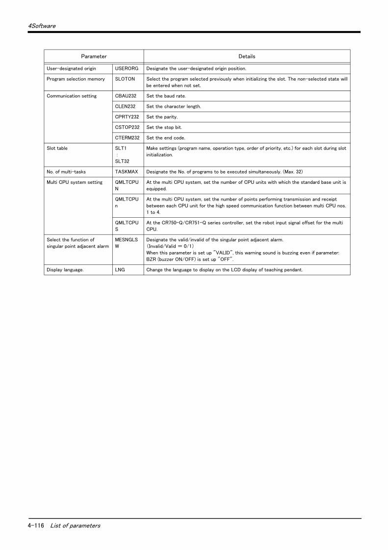
4-116 List of parameters
4Software
User-designated origin USERORG Designate the user-designated origin position.
Program selection memory SLOTON Select the program selected previously when initializing the slot. The non-selected state will
be entered when not set.
Communication setting CBAU232 Set the baud rate.
CLEN232 Set the character length.
CPRTY232 Set the parity.
CSTOP232 Set the stop bit.
CTERM232 Set the end code.
Slot table SLT1
:SLT32
Make settings (program name, operation type, order of priority, etc.) for each slot during slot
initialization.
No. of multi-tasks TASKMAX Designate the No. of programs to be executed simultaneously. (Max. 32)
Multi CPU system setting QMLTCPUN
At the multi CPU system, set the number of CPU units with which the standard base unit is equipped.
QMLTCPUn
At the multi CPU system, set the number of points performing transmission and receipt between each CPU unit for the high speed communication function between multi CPU nos.
1 to 4.
QMLTCPUS
At the CR750-Q/CR751-Q series controller, set the robot input signal offset for the multi CPU.
Select the function of singular point adjacent alarm
MESNGLSW
Designate the valid/invalid of the singular point adjacent alarm.(Invalid/Valid = 0/1)
When this parameter is set up "VALID", this warning sound is buzzing even if parameter:
BZR (buzzer ON/OFF) is set up "OFF".
Display language. LNG Change the language to display on the LCD display of teaching pendant.
Parameter Details
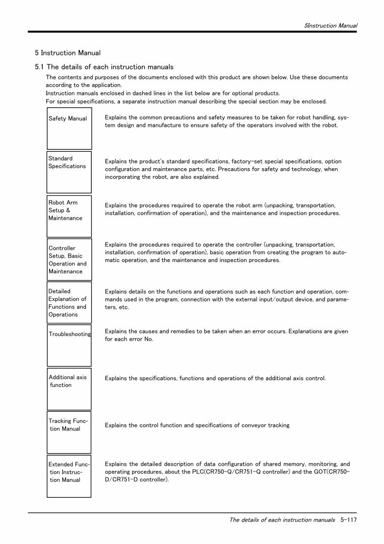
5Instruction Manual
The details of each instruction manuals 5-117
5 Instruction Manual
5.1 The details of each instruction manuals
The contents and purposes of the documents enclosed with this product are shown below. Use these documents according to the application.
Instruction manuals enclosed in dashed lines in the list below are for optional products.
For special specifications, a separate instruction manual describing the special section may be enclosed.
Explains the common precautions and safety measures to be taken for robot handling, sys-tem design and manufacture to ensure safety of the operators involved with the robot.
Explains the product's standard specifications, factory-set special specifications, option configuration and maintenance parts, etc. Precautions for safety and technology, when incorporating the robot, are also explained.
Explains the procedures required to operate the robot arm (unpacking, transportation, installation, confirmation of operation), and the maintenance and inspection procedures.
Explains the procedures required to operate the controller (unpacking, transportation, installation, confirmation of operation), basic operation from creating the program to auto-matic operation, and the maintenance and inspection procedures.
Explains details on the functions and operations such as each function and operation, com-mands used in the program, connection with the external input/output device, and parame-ters, etc.
Explains the causes and remedies to be taken when an error occurs. Explanations are given for each error No.
Explains the specifications, functions and operations of the additional axis control.
Explains the control function and specifications of conveyor tracking
Explains the detailed description of data configuration of shared memory, monitoring, andoperating procedures, about the PLC(CR750-Q/CR751-Q controller) and the GOT(CR750-D/CR751-D controller).
Safety Manual
StandardSpecifications
Robot ArmSetup &Maintenance
ControllerSetup, BasicOperation andMaintenance
Detailed Explanation ofFunctions andOperations
Troubleshooting
Additional axis function
Tracking Func-tion Manual
Extended Func-tion Instruc-tion Manual
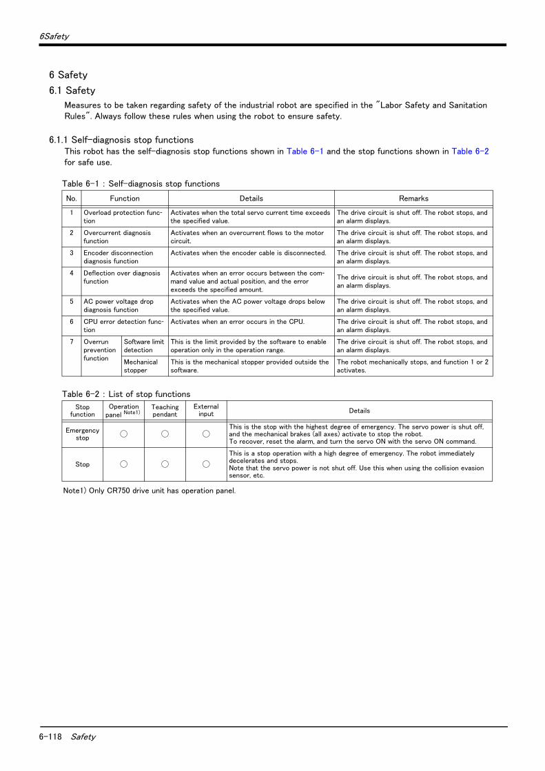
6-118 Safety
6Safety
6 Safety
6.1 Safety
Measures to be taken regarding safety of the industrial robot are specified in the "Labor Safety and Sanitation Rules". Always follow these rules when using the robot to ensure safety.
6.1.1 Self-diagnosis stop functionsThis robot has the self-diagnosis stop functions shown in Table 6-1 and the stop functions shown in Table 6-2 for safe use.
Table 6-1 : Self-diagnosis stop functions
Table 6-2 : List of stop functions
No. Function Details Remarks
1 Overload protection func-tion
Activates when the total servo current time exceeds the specified value.
The drive circuit is shut off. The robot stops, and an alarm displays.
2 Overcurrent diagnosis function
Activates when an overcurrent flows to the motor circuit.
The drive circuit is shut off. The robot stops, and an alarm displays.
3 Encoder disconnection diagnosis function
Activates when the encoder cable is disconnected. The drive circuit is shut off. The robot stops, and an alarm displays.
4 Deflection over diagnosis function
Activates when an error occurs between the com-mand value and actual position, and the error exceeds the specified amount.
The drive circuit is shut off. The robot stops, and an alarm displays.
5 AC power voltage drop diagnosis function
Activates when the AC power voltage drops below the specified value.
The drive circuit is shut off. The robot stops, and an alarm displays.
6 CPU error detection func-tion
Activates when an error occurs in the CPU. The drive circuit is shut off. The robot stops, and an alarm displays.
7 Overrun prevention function
Software limit detection
This is the limit provided by the software to enable operation only in the operation range.
The drive circuit is shut off. The robot stops, and an alarm displays.
Mechanical stopper
This is the mechanical stopper provided outside the software.
The robot mechanically stops, and function 1 or 2 activates.
Stopfunction
Operationpanel Note1)
Note1) Only CR750 drive unit has operation panel.
Teaching pendant
Externalinput Details
Emergencystop
◯ ◯ ◯ This is the stop with the highest degree of emergency. The servo power is shut off, and the mechanical brakes (all axes) activate to stop the robot.To recover, reset the alarm, and turn the servo ON with the servo ON command.
Stop ◯ ◯ ◯
This is a stop operation with a high degree of emergency. The robot immediately decelerates and stops.Note that the servo power is not shut off. Use this when using the collision evasion sensor, etc.
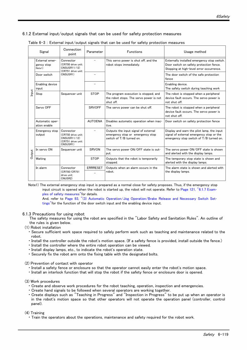
6Safety
Safety 6-119
6.1.2 External input/output signals that can be used for safety protection measures
Table 6-3 : External input/output signals that can be used for safety protection measures
6.1.3 Precautions for using robotThe safety measures for using the robot are specified in the "Labor Safety and Sanitation Rules". An outline of the rules is given below.
(1) Robot installation・ Secure sufficient work space required to safely perform work such as teaching and maintenance related to the
robot.・ Install the controller outside the robot's motion space. (If a safety fence is provided, install outside the fence.)・ Install the controller where the entire robot operation can be viewed.・ Install display lamps, etc., to indicate the robot's operation state.・ Securely fix the robot arm onto the fixing table with the designated bolts.
(2) Prevention of contact with operator・ Install a safety fence or enclosure so that the operator cannot easily enter the robot's motion space.・ Install an interlock function that will stop the robot if the safety fence or enclosure door is opened.
(3) Work procedures・ Create and observe work procedures for the robot teaching, operation, inspection and emergencies.・ Create hand signals to be followed when several operators are working together.・ Create displays such as "Teaching in Progress" and "Inspection in Progress" to be put up when an operator is
in the robot's motion space so that other operators will not operate the operation panel (controller, controlpanel).
(4) Training・ Train the operators about the operations, maintenance and safety required for the robot work.
SignalConnection
pointParameter Functions Usage method
Inpu
t
External emer-gency stop Note1)
Note1) The external emergency stop input is prepared as a normal close for safety proposes. Thus, if the emergency stopinput circuit is opened when the robot is started up, the robot will not operate. Refer to Page 121, "6.1.7 Exam-ples of safety measures"for details. And, refer to Page 93, "(3) Automatic Operation/Jog Operation/Brake Release and Necessary Switch Set-tings"for the function of the door switch input and the enabling device input.
Connector(CR750 drive unit:CNSUSR11/12)(CR751 drive unit:CNSUSR1)
- This servo power is shut off, and the
robot stops immediately.
Externally installed emergency stop switch.
Door switch on safety protection fence.
Stopping at high-level error occurrence.
Door switch - The door switch of the safe protection
fence
Enabling device
input
- Enabling device.
The safety switch during teaching work
Stop Sequencer unit STOP The program execution is stopped, and
the robot stops. The servo power is not
shut off.
The robot is stopped when a peripheral
device fault occurs. The servo power is
not shut off.
Servo OFF SRVOFF The servo power can be shut off. The robot is stopped when a peripheral
device fault occurs. The servo power is not shut off.
Automatic oper-ation enable
AUTOENA Disables automatic operation when inac-tive.
Door switch on safety protection fence
Outp
ut
Emergency stop output
Connector(CR750 drive unit:CNSUSR11/12)(CR751 drive unit:CNSUSR1)
- Outputs the input signal of external emergency stop or emergency stop switch of T/B turned on.
Display and warn the pilot lamp, the input signal of external emergency stop or the emergency stop switch of T/B turned on.
In servo ON Sequencer unit SRVON The servo power ON/OFF state is out-put.
The servo power ON/OFF state is shown and alerted with the display lamps.
Waiting STOP Outputs that the robot is temporarily stopped.
The temporary stop state is shown and alerted with the display lamps.
In alarm Connector(CR750/CR751 drive unit: CNUSR2)
ERRRESET Outputs when an alarm occurs in the robot.
The alarm state is shown and alerted with the display lamps.
-

6-120 Safety
6Safety
・ Only trained and registered operators must operate the robot.Participation in the "Special training for industrial robots" sponsored by the Labor Safety and Sanitation Com-mittee, etc., is recommended for safety training.
(5) Daily inspection and periodic inspection・ Always inspect the robot before starting daily operations and confirm that there are no abnormalities.・ Set the periodic inspection standards in view of the robot's ambient environment and operation frequency, and
perform periodic inspections.・ Make records when periodic inspections and repairs have been done, and store the records for three or more
years.
6.1.4 Safety measures for automatic operation(1) Install safety fences so that operators will not enter the operation area during operation and indicate that
automatic operation is in progress with lamps, etc.(2) Create signals to be given when starting operation, assign a person to give the signal, and make sure that the
operator follows the signals.
6.1.5 Safety measures for teachingObserve the following measures when teaching, etc., in the robot's operation range.(1) Specify and follow items such as procedures related to teaching work, etc. (2) Take measures so that operation can be stopped immediately in case of trouble, and measures so that oper-
ation can be restarted.(3) Take measures with the robot start switch, etc., to indicate that teaching work is being done.(4) Always inspect that stop functions such as the emergency stop device before starting the work.(5) Immediately stop the work when trouble occurs, and correct the trouble.(6) Take measures so that the work supervisor can immediately stop the robot operation when trouble occurs.(7) The teaching operator must have completed special training regarding safety. (Training regarding industrial
robots and work methods, etc.)(8) Create signals to be used when several operators are working together.
6.1.6 Safety measures for maintenance and inspections, etc.Turn the power OFF and take measures to prevent operators other than the relevant operator from pressing the start switch when performing inspections, repairs, adjustments, cleaning or oiling.If operation is required, take measures to prevent hazards caused by unintentional or mistaken operations.(1) Specify and follow items such as procedures related to maintenance work, etc. (2) Take measures so that operation can be stopped immediately in case of trouble, and measures so that oper-
ation can be restarted.(3) Take measures with the robot start switch, etc., to indicate that work is being done.(4) Take measures so that the work supervisor can immediately stop the robot operation when trouble occurs.(5) The operator must have completed special training regarding safety. (Training regarding industrial robots and
work methods, etc.)(6) Create signals to be used when several operators are working together.
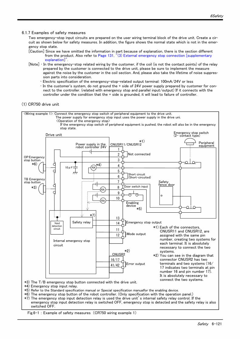
6Safety
Safety 6-121
6.1.7 Examples of safety measuresTwo emergency-stop input circuits are prepared on the user wiring terminal block of the drive unit. Create a cir-cuit as shown below for safety measures. In addition, the figure shows the normal state which is not in the emer-gency stop state.[Caution] Since we have omitted the information in part because of explanation, there is the section different
from the product. Also refer to Page 131, "(3) External emergency stop connection [supplementary explanation]".
[Note] ・ In the emergency-stop related wiring by the customer, if the coil (is not the contact points) of the relay prepared by the customer is connected to the drive unit, please be sure to implement the measure against the noise by the customer in the coil section. And, please also take the lifetime of noise suppres-sion parts into consideration.
・ Electric specification of the emergency-stop-related output terminal: 100mA/24V or less・ In the customer's system, do not ground the + side of 24V power supply prepared by customer for con-
nect to the controller. (related with emergency stop and parallel input/output) If it connects with the controller under the condition that the + side is grounded, it will lead to failure of controller.
(1) CR750 drive unit
Fig.6-1 : Example of safety measures (CR750 wiring example 1)
<Wiring example 1>: Connect the emergency stop switch of peripheral equipment to the drive unit. The power supply for emergency stop input uses the power supply in the drive uni.<Operation of the emergency stop>
If the emergency stop switch of peripheral equipment is pushed, the robot will also be in the emergency stop state.
非常停止スイッチ(2接点タイプ)
周辺装置
安全柵のドア
1
CNUSR11/CNUSR12
CNUSR2
内部非常停止回路
非常停止出力
モード出力
OP非常停止ボタン
RA
RA
RA
}
ドアスイッチ入力
イネーブリングデバイス
2
3
4
5
6
7
8
9
10
13
14
11
12
16/17
41/42 エラー出力}
短絡
短絡
}
TB非常停止ボタン
内部電源 24V
安全リレー入力検知回路
10μF
*1) Each of the connectors, CNUSR11 and CNUSR12, are assigned with the same pin number, creating two systems for each terminal. It is absolutely necessary to connect the two systems.
*2) You can see in the diagram that connector CNUSR2 has two terminals and two systems (16/17 indicates two terminals at pin number 16 and pin number 17). It is absolutely necessary to connect the two systems.
Drive unit
*3) The T/B emergency stop button connected with the drive unit.*4) Emergency stop input relay.*5) Refer to the Standard specification manual or Special specification manualfor the enabling device.*6) The emergency stop button of the robot controller. (Only specification with the operation panel.)*7) The emergency stop input detection relay is used the drive unit’s internal safety relay control. If the
emergency stop input detection relay is switched OFF, emergency stop is detected and the safety relay is also switched OFF.
Power supply in the robot controller 24V
OP Emergency stop button
TB Emergency stop button
Not connected
Door switch input
Enabling device
Mode output
Error output
Emergency stop outputSafety relay
Internal emergency stop circuit
Emergency stop switch (2- contact type)
Peripheral equipment
Safety fence door
*1)
*2)
*3)
*6) *4)
*5)
*7)
Short circuit(Short-circuited)
Input detection
circuit
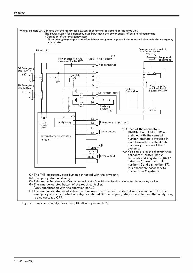
6-122 Safety
6Safety
Fig.6-2 : Example of safety measures (CR750 wiring example 2)
非常停止スイッチ(2接点タイプ)
周辺装置
安全柵のドア
周辺装置側電源24V
CNUSR2
内部非常停止回路
未接続
非常停止出力
モード出力
RA
RA
RA
}
ドアスイッチ入力
イネーブリングデバイス
16/17
41/42 エラー出力}
}
1
CNUSR11/CNUSR12
2
3
4
5
6
7
8
9
10
13
14
11
12
OP非常停止ボタン
TB非常停止ボタン
内部電源 24V
安全リレー入力検知回路
10μF
*1) Each of the connectors, CNUSR11 and CNUSR12, are assigned with the same pin number, creating 2 systems in each terminal. It is absolutely necessary to connect the 2 systems.
*2) You can see in the diagram that connector CNUSR2 has 2 terminals and 2 systems (16/17 indicates 2 terminals at pin number 16 and pin number 17). It is absolutely necessary to connect the 2 systems.
<Wiring example 2>: Connect the emergency stop switch of peripheral equipment to the drive unit. The power supply for emergency stop input uses the power supply of peripheral equipment. <Operation of the emergency stop>
If the emergency stop switch of peripheral equipment is pushed, the robot will also be in the emergency stop state.
Drive unit
*3) The T/B emergency stop button connected with the drive unit.*4) Emergency stop input relay.*5) Refer to the Standard specification manual or the Special specification manual for the enabling device.*6) The emergency stop button of the robot controller.
(Only specification with the operation panel.)*7) The emergency stop input detection relay uses the drive unit’s internal safety relay control. If the
emergency stop input detection relay is switched OFF, emergency stop is detected and the safety relay is also switched OFF.
Power supply in the robot controller 24V
OP Emergency stop button
TB Emergency stop button
Not connected
Door switch input
Enabling device
Mode output
Error output
Emergency stop outputSafety relay
Internal emergency stop circuit
Emergency stop switch (2- contact type)
Peripheral equipment
Safety fence door
Power supply in the Peripheral equipment 24V
*1)
*2)
*3)
*6) *4)
*5)
*7)
Input detection
circuit
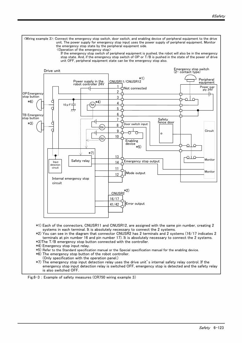
6Safety
Safety 6-123
Fig.6-3 : Example of safety measures (CR750 wiring example 3)
<Wiring example 3>: Connect the emergency stop switch, door switch, and enabling device of peripheral equipment to the drive unit. The power supply for emergency stop input uses the power supply of peripheral equipment. Monitor the emergency stop state by the peripheral equipment side.<Operation of the emergency stop>
If the emergency stop switch of peripheral equipment is pushed, the robot will also be in the emergency stop state. And, if the emergency stop switch of OP or T/B is pushed in the state of the power of drive unit OFF, peripheral equipment state can be the emergency stop also.
非常停止スイッチ(2接点タイプ)
周辺装置
安全柵のドア
周辺装置側電源24V
監視
周 辺 装 置 側 内 部 回 路
CNUSR2
内部非常停止回路
未接続
非常停止出力
モード出力
RA
RA
RA
}
ドアスイッチ入力
イネーブリングデバイス
16/17
41/42 エラー出力}
監視
1
CNUSR11/CNUSR12
2
3
4
5
6
7
8
9
10
13
14
11
12
OP非常停止ボタン
TB非常停止ボタン
内部電源 24V
安全リレー入力検知回路
10μF
Drive unit
*1) Each of the connectors, CNUSR11 and CNUSR12, are assigned with the same pin number, creating 2 systems in each terminal. It is absolutely necessary to connect the 2 systems.
*2) You can see in the diagram that connector CNUSR2 has 2 terminals and 2 systems (16/17 indicates 2 terminals at pin number 16 and pin number 17). It is absolutely necessary to connect the 2 systems.
*3)The T/B emergency stop button connected with the controller.*4) Emergency stop input relay.*5) Refer to the Standard specification manual or the Special specification manual for the enabling device.*6) The emergency stop button of the robot controller.
(Only specification with the operation panel.)*7) The emergency stop input detection relay uses the drive unit’s internal safety relay control. If the
emergency stop input detection relay is switched OFF, emergency stop is detected and the safety relay is also switched OFF.
Power supply in the robot controller 24V
OP Emergency stop button
TB Emergency stop button
Not connected
Door switch input
Enabling device
Mode output
Error output
Emergency stop outputSafety relay
Internal emergency stop circuit
Emergency stop switch (2- contact type)
Peripheral equipment
Safety fence door
Power sup-ply 24V
*1)
*2)
*3)
*6) *4)
*5)
*7)
Monitor
Monitor
Circuit
Input detection
circuit
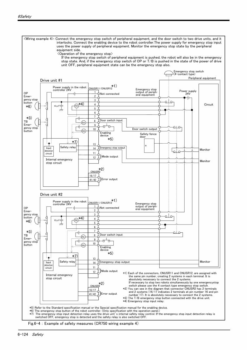
6-124 Safety
6Safety
Fig.6-4 : Example of safety measures (CR750 wiring example 4)
OP非常停止ボタン
TB非常停止ボタン
周辺装置の非常停止出力
周辺装置内部非常停止回路
周辺装置
非常停止スイッチ(4接点タイプ)
安全柵のドア
ドアスイッチ出力
監視
周辺装置の非常停止出力
周辺装置側電源24V
CNUSR2
内部非常停止回路
未接続
非常停止出力
モード出力
RA
RA
RA
}
ドアスイッチ入力
16/17
41/42 エラー出力}
監視
監視
CNUSR2
内部非常停止回路
未接続
非常停止出力
モード出力
RA
RA
RA
}
ドアスイッチ入力
16/17
41/42 エラー出力}
1
CNUSR11/CNUSR12
2
3
4
5
6
7
8
9
10
13
14
11
12
1
CNUSR11/CNUSR12
2
3
4
5
6
7
8
9
10
13
14
11
12
OP非常停止ボタン
TB非常停止ボタン
イネーブリングデバイス
イネーブリングデバイス
内部電源 24V
内部電源 24V
安全リレー
安全リレー
入力検知回路
10μF
入力検知回路
10μF
Drive unit #1
*5) Refer to the Standard specification manual or the Special specification manual for the enabling device.*6) The emergency stop button of the robot controller. (Only specification with the operation panel.)*7) The emergency stop input detection relay uses the drive unit’s internal safety relay control. If the emergency stop input detection relay is
switched OFF, emergency stop is detected and the safety relay is also switched OFF.
Power supply in the robot controller 24V
OP Emer-gency stop button
TB Emer-gency stop button
Not connected
Enabling device
Mode output
Error output
Emergency stop outputSafety relay
Internal emergency stop circuit
Emergency stop switch (4-contact type)
Peripheral equipment
Safety fence door
Power supply 24V
*1)
*2)
*3)
*6)*4)
*5)*7)
Monitor
Monitor
Circuit
Door switch input
Not connected
<Wiring example 4>: Connect the emergency stop switch of peripheral equipment, and the door switch to two drive units, and it interlocks. Connect the enabling device to the robot controller.The power supply for emergency stop input uses the power supply of peripheral equipment. Monitor the emergency stop state by the peripheral equipment side.<Operation of the emergency stop>
If the emergency stop switch of peripheral equipment is pushed, the robot will also be in the emergency stop state. And, if the emergency stop switch of OP or T/B is pushed in the state of the power of drive unit OFF, peripheral equipment state can be the emergency stop also.
Monitor
Door switch input
Enabling device
Emergency stop output
Power supply in the robot controller 24V
Safety relay
TB Emer-gency stop button
*3)
OP Emer-gency stop button
*6)
Drive unit #2
*1) Each of the connectors, CNUSR11 and CNUSR12, are assigned with the same pin number, creating 2 systems in each terminal. It is absolutely necessary to connect the 2 systems.If necessary to stop two robots simultaneously by one emergencystop switch please use the 4 contact type emergency stop switch.
*2) You can see in the diagram that connector CNUSR2 has 2 terminals and 2 systems (16/17 indicates 2 terminals at pin number 16 and pin number 17). It is absolutely necessary to connect the 2 systems.
*3) The T/B emergency stop button connected with the drive unit.*4) Emergency stop input relay.
Mode output
Error output
Internal emergency stop circuit
*1)
*2)
*7)
*4)
*5)
Emergency stop output of periph-eral equipment
Door switch output
Emergency stop output of periph-eral equipment
Input detection circuit
Input detection circuit
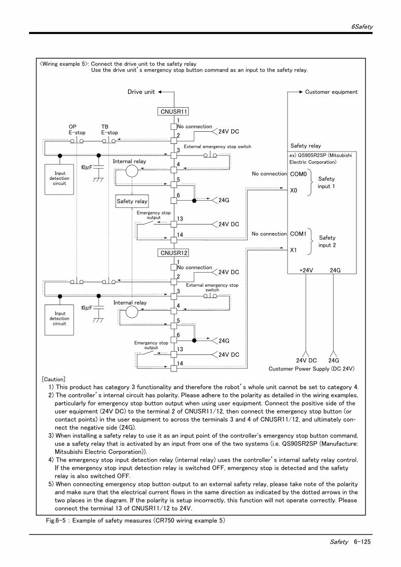
6Safety
Safety 6-125
Fig.6-5 : Example of safety measures (CR750 wiring example 5)
OPE-stop
1
2
3
4
5
6
CNUSR11
内部リレー
TBE-stop
24G
1
2
3
4
5
624G
内部リレー
X0
COM0
X1
COM1
No connection
No connection
安全入力1
安全入力2
24V DC 24G
例)QS90SR2SP ( 三菱電機株式会社)
安全リレー
お客様電源(DC 24V)
+24V 24G
お客様装置
24V DC
外部非常停止スイッチ
13
14
24V DC
24V DC
外部非常停止スイッチ
13
14
24V DC
安全リレー
非常停止出力
非常停止出力
CNUSR12
No connection
No connection
入力検知回路
10μF
入力検知回路
10μF
Drive unit
Safety relay
<Wiring example 5>: Connect the drive unit to the safety relay Use the drive unit’s emergency stop button command as an input to the safety relay.
Internal relay
Emergency stop output
Internal relay
External emergency stop switch
External emergency stop switch
Emergency stop output
Customer equipment
Safety relay
ex) QS90SR2SP (Mitsubishi
Electric Corporation)
Safety input 1
Customer Power Supply (DC 24V)
[Caution]
1) This product has category 3 functionality and therefore the robot’s whole unit cannot be set to category 4.2) The controller’s internal circuit has polarity. Please adhere to the polarity as detailed in the wiring examples,
particularly for emergency stop button output when using user equipment. Connect the positive side of the user equipment (24V DC) to the terminal 2 of CNUSR11/12, then connect the emergency stop button (or contact points) in the user equipment to across the terminals 3 and 4 of CNUSR11/12, and ultimately con-nect the negative side (24G).
3) When installing a safety relay to use it as an input point of the controller's emergency stop button command, use a safety relay that is activated by an input from one of the two systems (i.e. QS90SR2SP (Manufacture: Mitsubishi Electric Corporation)).
4) The emergency stop input detection relay (internal relay) uses the controller’s internal safety relay control. If the emergency stop input detection relay is switched OFF, emergency stop is detected and the safety relay is also switched OFF.
5) When connecting emergency stop button output to an external safety relay, please take note of the polarity and make sure that the electrical current flows in the same direction as indicated by the dotted arrows in the two places in the diagram. If the polarity is setup incorrectly, this function will not operate correctly. Please connect the terminal 13 of CNUSR11/12 to 24V.
Safety input 2
Input detection
circuit
Input detection
circuit
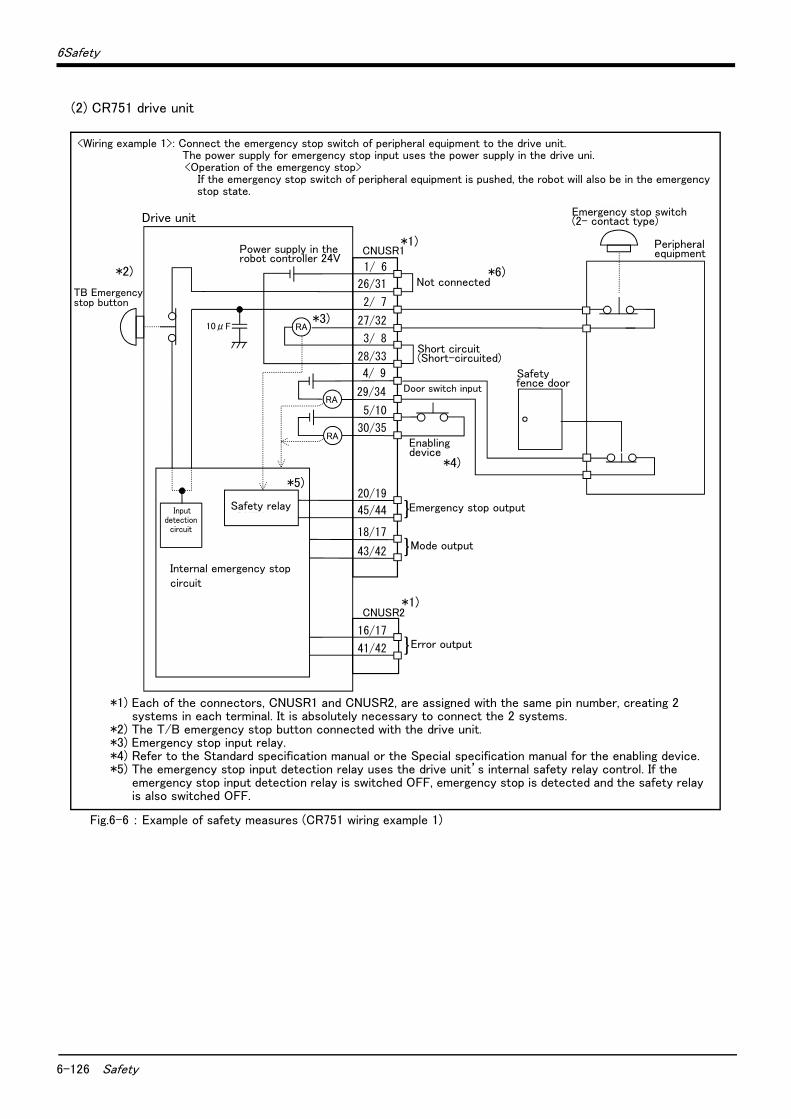
6-126 Safety
6Safety
(2) CR751 drive unit
Fig.6-6 : Example of safety measures (CR751 wiring example 1)
非常停止スイッチ(2接点タイプ)
周辺装置
安全柵のドア
1/ 6
CNUSR1
CNUSR2
内部非常停止回路
コントローラ
非常停止出力
モード出力
TB非常停止ボタン
RA
RA
RA
}
ドアスイッチ入力
イネーブリングデバイス
26/31
2/ 7
27/32
3/ 8
28/33
4/ 9
29/34
5/10
30/35
20/19
45/44
18/17
43/42
16/17
41/42 エラー出力}
短絡
短絡
}安全リレー
内部電源 24V
入力検知回路
10μF
<Wiring example 1>: Connect the emergency stop switch of peripheral equipment to the drive unit. The power supply for emergency stop input uses the power supply in the drive uni.<Operation of the emergency stop>
If the emergency stop switch of peripheral equipment is pushed, the robot will also be in the emergency stop state.
Drive unit
*1) Each of the connectors, CNUSR1 and CNUSR2, are assigned with the same pin number, creating 2 systems in each terminal. It is absolutely necessary to connect the 2 systems.
*2) The T/B emergency stop button connected with the drive unit.*3) Emergency stop input relay.*4) Refer to the Standard specification manual or the Special specification manual for the enabling device.*5) The emergency stop input detection relay uses the drive unit’s internal safety relay control. If the
emergency stop input detection relay is switched OFF, emergency stop is detected and the safety relay is also switched OFF.
Power supply in the robot controller 24V
TB Emergency stop button
Not connected
Door switch input
Enabling device
Mode output
Error output
Emergency stop outputSafety relay
Internal emergency stop circuit
Emergency stop switch (2- contact type)
Peripheral equipment
Safety fence door
*1)
*1)
*4)
Short circuit(Short-circuited)
*2)
*3)
*5)
*6)
Input detection
circuit
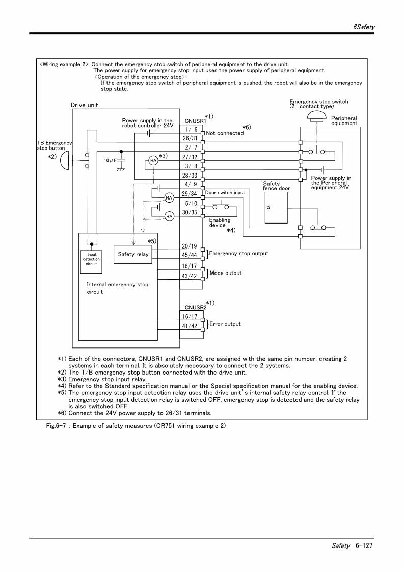
6Safety
Safety 6-127
Fig.6-7 : Example of safety measures (CR751 wiring example 2)
非常停止スイッチ(2接点タイプ)
周辺装置
安全柵のドア
周辺装置側電源24V
1/ 6
CNUSR1
CNUSR2
内部非常停止回路
コントローラ
未接続
非常停止出力
モード出力
TB非常停止ボタン
RA
RA
RA
}
ドアスイッチ入力
イネーブリングデバイス
26/31
2/ 7
27/32
3/ 8
28/33
4/ 9
29/34
5/10
30/35
16/17
41/42 エラー出力}
}20/19
45/44
18/17
43/42
安全リレー
内部電源 24V
入力検知回路
10μF
<Wiring example 2>: Connect the emergency stop switch of peripheral equipment to the drive unit. The power supply for emergency stop input uses the power supply of peripheral equipment. <Operation of the emergency stop>
If the emergency stop switch of peripheral equipment is pushed, the robot will also be in the emergency stop state.
Drive unit
Power supply in the robot controller 24V
TB Emergency stop button
Not connected
Door switch input
Enabling device
Mode output
Error output
Emergency stop outputSafety relay
Internal emergency stop circuit
Emergency stop switch (2- contact type)
Safety fence door
Power supply in the Peripheral equipment 24V
*1)
*1)
*3)
*4)
*5)
Peripheral equipment
*1) Each of the connectors, CNUSR1 and CNUSR2, are assigned with the same pin number, creating 2 systems in each terminal. It is absolutely necessary to connect the 2 systems.
*2) The T/B emergency stop button connected with the drive unit.*3) Emergency stop input relay.*4) Refer to the Standard specification manual or the Special specification manual for the enabling device.*5) The emergency stop input detection relay uses the drive unit’s internal safety relay control. If the
emergency stop input detection relay is switched OFF, emergency stop is detected and the safety relay is also switched OFF.
*6) Connect the 24V power supply to 26/31 terminals.
*2)
*6)
Input detection
circuit
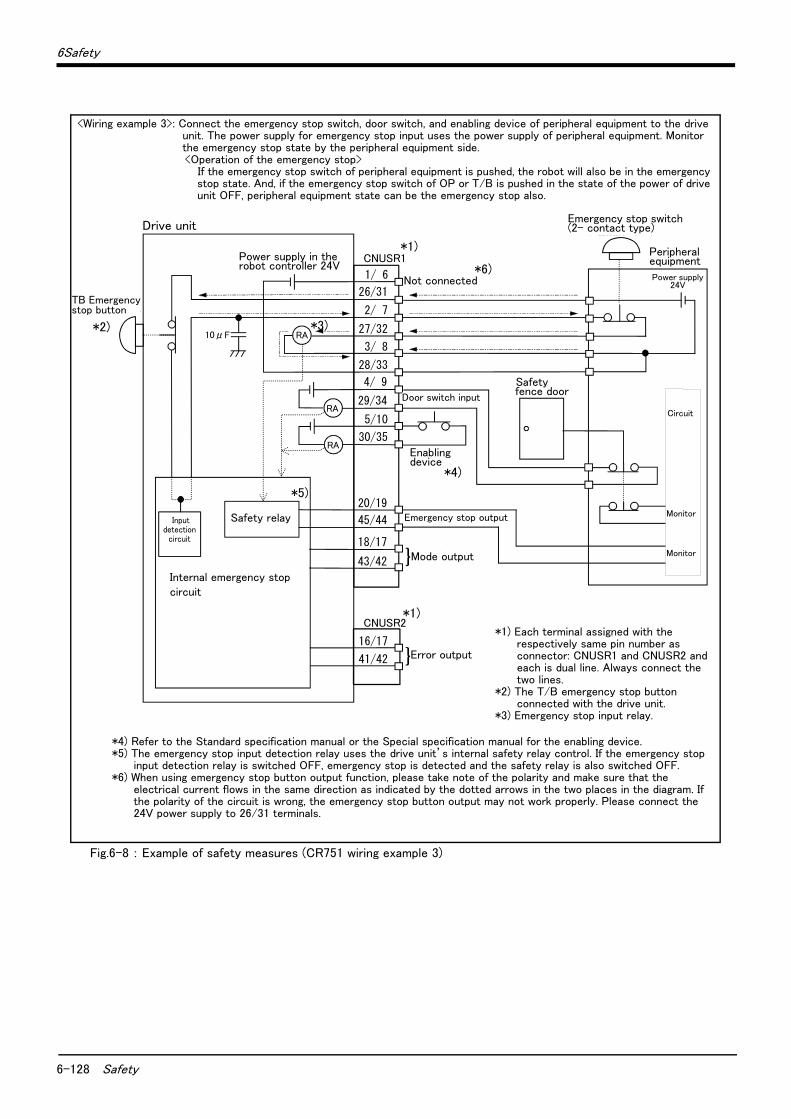
6-128 Safety
6Safety
Fig.6-8 : Example of safety measures (CR751 wiring example 3)
非常停止スイッチ(2接点タイプ)
周辺装置
安全柵のドア
周辺装置側電源24V
監視
周 辺 装 置 側 内 部 回 路
1/ 6
CNUSR1
CNUSR2
内部非常停止回路
コントローラ
未接続
非常停止出力
モード出力
TB非常停止ボタン
RA
RA
RA
}
ドアスイッチ入力
イネーブリングデバイス
26/31
2/ 7
27/32
3/ 8
28/33
4/ 9
29/34
5/10
30/35
16/17
41/42 エラー出力}
20/19
45/44
18/17
43/42監視
安全リレー
内部電源 24V
入力検知回路
10μF
Drive unit
Power supply in the robot controller 24V
TB Emergency stop button
Not connected
Door switch input
Enabling device
Mode output
Error output
Emergency stop outputSafety relay
Internal emergency stop circuit
Emergency stop switch (2- contact type)
Safety fence door
Power supply 24V
*1)
*1)
*3)
*4)
*5)
Peripheral equipment
*4) Refer to the Standard specification manual or the Special specification manual for the enabling device.*5) The emergency stop input detection relay uses the drive unit’s internal safety relay control. If the emergency stop
input detection relay is switched OFF, emergency stop is detected and the safety relay is also switched OFF.*6) When using emergency stop button output function, please take note of the polarity and make sure that the
electrical current flows in the same direction as indicated by the dotted arrows in the two places in the diagram. If the polarity of the circuit is wrong, the emergency stop button output may not work properly. Please connect the 24V power supply to 26/31 terminals.
*2)
*6)
<Wiring example 3>: Connect the emergency stop switch, door switch, and enabling device of peripheral equipment to the drive unit. The power supply for emergency stop input uses the power supply of peripheral equipment. Monitor the emergency stop state by the peripheral equipment side.<Operation of the emergency stop>
If the emergency stop switch of peripheral equipment is pushed, the robot will also be in the emergency stop state. And, if the emergency stop switch of OP or T/B is pushed in the state of the power of drive unit OFF, peripheral equipment state can be the emergency stop also.
Monitor
Monitor
Circuit
*1) Each terminal assigned with the respectively same pin number as connector: CNUSR1 and CNUSR2 and each is dual line. Always connect the two lines.
*2) The T/B emergency stop button connected with the drive unit.
*3) Emergency stop input relay.
Input detection
circuit
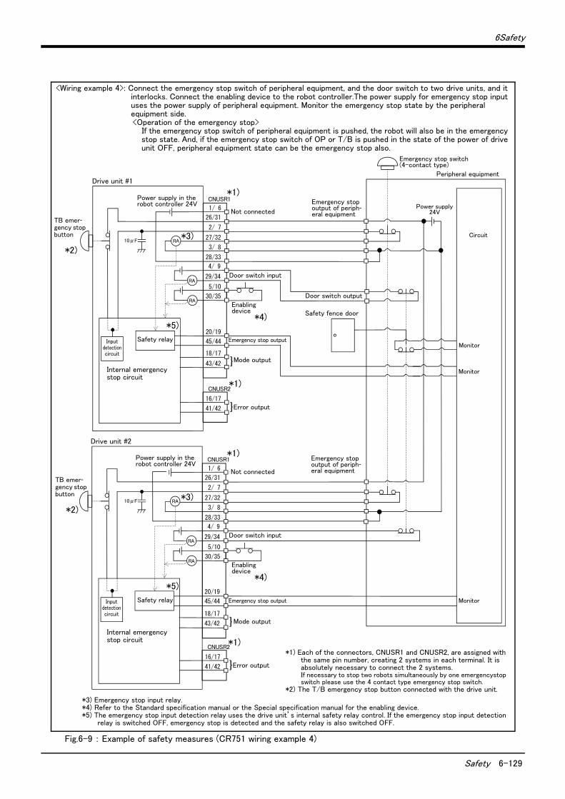
6Safety
Safety 6-129
Fig.6-9 : Example of safety measures (CR751 wiring example 4)
周辺装置の非常停止出力
周辺装置内部非常停止回路
周辺装置
非常停止スイッチ(4接点タイプ)
安全柵のドア
ドアスイッチ出力
監視
周辺装置の非常停止出力
周辺装置側電源24V
1/ 6
CNUSR1
CNUSR2
内部非常停止回路
コントローラ #1
未接続
非常停止出力
モード出力
TB非常停止ボタン
RA
RA
RA
}
内部電源 24V
ドアスイッチ入力
イネーブリングデバイス
26/31
2/ 7
27/32
3/ 8
28/33
4/ 9
29/34
5/10
30/35
16/17
41/42 エラー出力}
監視
監視
1/ 6
CNUSR1
CNUSR2
内部非常停止回路
コントローラ #2
未接続
非常停止出力
モード出力
TB非常停止ボタン
RA
RA
RA
}
ドアスイッチ入力
イネーブリングデバイス
26/31
2/ 7
27/32
3/ 8
28/33
4/ 9
29/34
5/10
30/35
16/17
41/42 エラー出力}
20/19
45/44
18/17
43/42
20/19
45/44
18/17
43/42
安全リレー
安全リレー
内部電源 24V
入力検知回路
入力検知回路
10μF
10μF
Drive unit #1
Power supply in the robot controller 24V
TB emer-gency stop button
Not connected
Door switch input
Enabling device
Mode output
Error output
Emergency stop output
Safety relay
Internal emergency stop circuit
Emergency stop switch (4-contact type)
Safety fence door
Power supply 24V
*1)
*1)
*3)
*4)
*5)
Peripheral equipment
*3) Emergency stop input relay.*4) Refer to the Standard specification manual or the Special specification manual for the enabling device.*5) The emergency stop input detection relay uses the drive unit’s internal safety relay control. If the emergency stop input detection
relay is switched OFF, emergency stop is detected and the safety relay is also switched OFF.
*2)
Monitor
Monitor
<Wiring example 4>: Connect the emergency stop switch of peripheral equipment, and the door switch to two drive units, and it interlocks. Connect the enabling device to the robot controller.The power supply for emergency stop input uses the power supply of peripheral equipment. Monitor the emergency stop state by the peripheral equipment side.<Operation of the emergency stop>
If the emergency stop switch of peripheral equipment is pushed, the robot will also be in the emergency stop state. And, if the emergency stop switch of OP or T/B is pushed in the state of the power of drive unit OFF, peripheral equipment state can be the emergency stop also.
*1)
*1)
Drive unit #2
TB emer-gency stop button
*2)
Power supply in the robot controller 24V
Not connected
Door switch input
Mode output
Error output
Safety relay
*5)
Internal emergency stop circuit
Enabling device
*4)
Emergency stop output
Circuit
Monitor
*3)
*1) Each of the connectors, CNUSR1 and CNUSR2, are assigned with the same pin number, creating 2 systems in each terminal. It is absolutely necessary to connect the 2 systems.If necessary to stop two robots simultaneously by one emergencystop switch please use the 4 contact type emergency stop switch.
*2) The T/B emergency stop button connected with the drive unit.
Emergency stop output of periph-eral equipment
Door switch output
Emergency stop output of periph-eral equipment
Input detection circuit
Input detection circuit
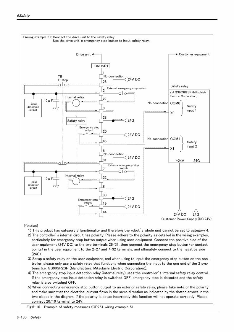
6-130 Safety
6Safety
Fig.6-10 : Example of safety measures (CR751 wiring example 5)
1
26
2
27
3
28
CNUSR1
内部リレー
TBE-stop
24G
6
31
7
32
8
3324G
内部リレー
X0
COM0
X1
COM1
No connection
No connection
安全入力1
安全入力2
24V DC 24G
安全リレー
お客様電源(DC 24V)
+24V 24G
お客様装置
24V DC
外部非常停止スイッチ
20
45
24V DC
24V DC
外部非常停止スイッチ
19
44
24V DC
安全リレー
非常停止出力
非常停止出力
No connection
No connection
例)QS90SR2SP ( 三菱電機株式会社)
入力検知回路
10μF
入力検知回路
10μF
Drive unit
<Wiring example 5>: Connect the drive unit to the safety relay Use the drive unit’s emergency stop button to input safety relay.
Safety relay
Internal relay
Emergency stop output
External emergency stop switch
Customer equipment
Safety relay
Customer Power Supply (DC 24V)
Internal relay
Emergency stop output
External emergency stop switch
[Caution]
1) This product has category 3 functionality and therefore the robot’s whole unit cannot be set to category 4.2) The controller’s internal circuit has polarity. Please adhere to the polarity as detailed in the wiring examples,
particularly for emergency stop button output when using user equipment. Connect the positive side of the user equipment (24V DC) to the two terminals 26/31, then connect the emergency stop button (or contact points) in the user equipment to the 2-27 and 7-32 terminals, and ultimately connect to the negative side (24G).
3) Setup a safety relay on the user equipment, and when using to input the emergency stop button on the con-troller, please only use a safety relay that functions when connecting the input to the one end of the 2 sys-tems (i.e. QS90SR2SP (Manufacture: Mitsubishi Electric Corporation)).
4) The emergency stop input detection relay (internal relay) uses the controller’s internal safety relay control. If the emergency stop input detection relay is switched OFF, emergency stop is detected and the safety relay is also switched OFF.
5) When connecting emergency stop button output to an exterior safety relay, please take note of the polarity and make sure that the electrical current flows in the same direction as indicated by the dotted arrows in the two places in the diagram. If the polarity is setup incorrectly this function will not operate correctly. Please connect 20/19 terminal to 24V.
ex) QS90SR2SP (Mitsubishi Electric Corporation)
Safety input 1
Safety input 2
Input detection
circuit
Input detection
circuit
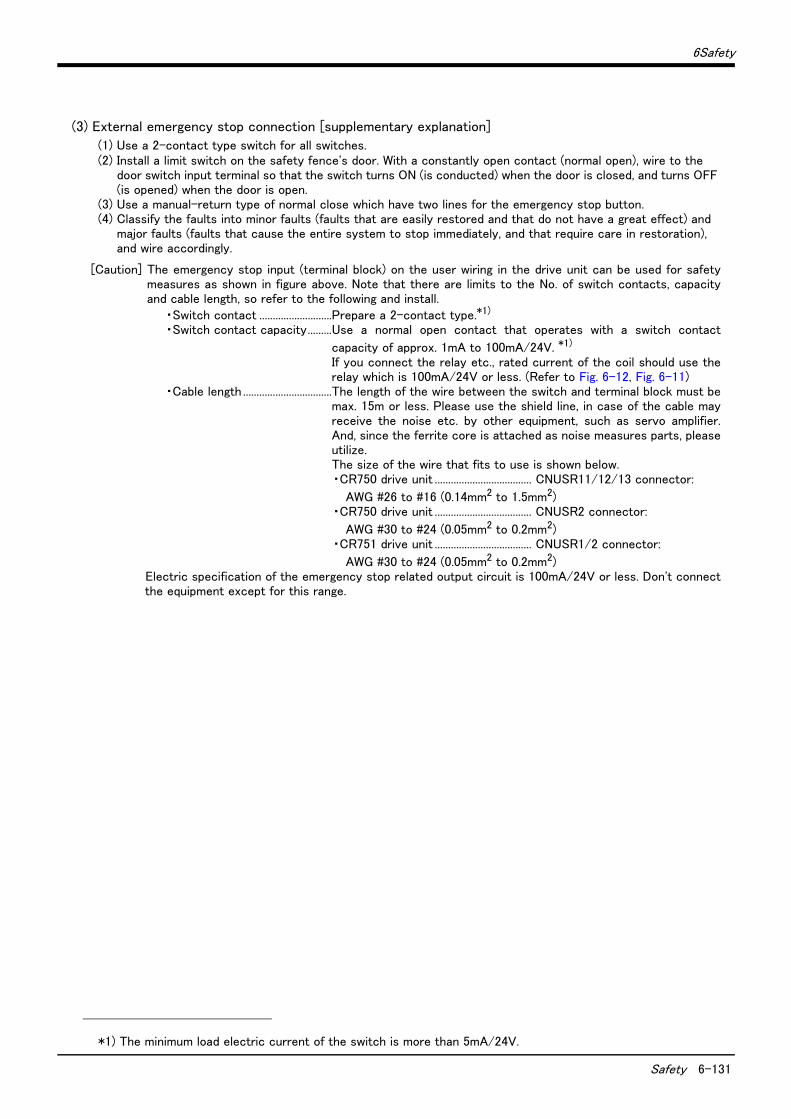
6Safety
Safety 6-131
(3) External emergency stop connection [supplementary explanation]
(1) Use a 2-contact type switch for all switches.(2) Install a limit switch on the safety fence's door. With a constantly open contact (normal open), wire to the
door switch input terminal so that the switch turns ON (is conducted) when the door is closed, and turns OFF (is opened) when the door is open.
(3) Use a manual-return type of normal close which have two lines for the emergency stop button.(4) Classify the faults into minor faults (faults that are easily restored and that do not have a great effect) and
major faults (faults that cause the entire system to stop immediately, and that require care in restoration), and wire accordingly.
[Caution] The emergency stop input (terminal block) on the user wiring in the drive unit can be used for safetymeasures as shown in figure above. Note that there are limits to the No. of switch contacts, capacityand cable length, so refer to the following and install.
・Switch contact ...........................Prepare a 2-contact type.*1)
・Switch contact capacity.........Use a normal open contact that operates with a switch contact
capacity of approx. 1mA to 100mA/24V. *1)
If you connect the relay etc., rated current of the coil should use therelay which is 100mA/24V or less. (Refer to Fig. 6-12, Fig. 6-11)
・Cable length .................................The length of the wire between the switch and terminal block must bemax. 15m or less. Please use the shield line, in case of the cable mayreceive the noise etc. by other equipment, such as servo amplifier.And, since the ferrite core is attached as noise measures parts, pleaseutilize.The size of the wire that fits to use is shown below.・CR750 drive unit .................................... CNUSR11/12/13 connector:
AWG #26 to #16 (0.14mm2 to 1.5mm2)・CR750 drive unit .................................... CNUSR2 connector:
AWG #30 to #24 (0.05mm2 to 0.2mm2)・CR751 drive unit .................................... CNUSR1/2 connector:
AWG #30 to #24 (0.05mm2 to 0.2mm2)Electric specification of the emergency stop related output circuit is 100mA/24V or less. Don't connectthe equipment except for this range.
*1) The minimum load electric current of the switch is more than 5mA/24V.
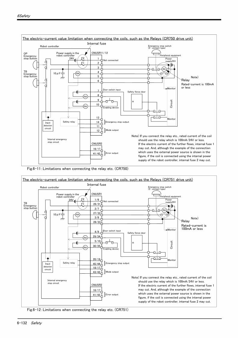
6-132 Safety
6Safety
Fig.6-11:Limitations when connecting the relay etc. (CR750)
Fig.6-12:Limitations when connecting the relay etc. (CR751)
1
2
3
4
5
6
13
14
11
12
16/17
41/42
CNUSR11/12
CNUSR2
エラー出力
内部非常停止回路
ロボットコントローラ
未接続
非常停止スイッチ(2接点タイプ)
非常停止出力
モード出力
周辺装置
TB非常停止ボタン
OP非常停止ボタン
}
RA
RA
RA
}
}
ロボットコントローラ内電源 24V
ドアスイッチ入力安全柵のドア
イネーブリングデバイス
周辺装置側電源24V
監視
監視
周 辺 装 置 側 内 部 回 路
RA
安全リレー
7
8
9
10
F2
F1
入力検知回路
10μF
The electric-current value limitation when connecting the coils, such as the Relays (CR750 drive unit)
RelayRated-current is 100mA or less
Note) If you connect the relay etc., rated current of the coil
should use the relay which is 100mA/24V or less. If the electric current of the further flows, internal fuse 1
may cut. And, although the example of the connection which uses the external power source is shown in the
figure, if the coil is connected using the internal power
supply of the robot controller, internal fuse 2 may cut.
Internal fuse
Not connected
Door switch inputSafety fence door
Enabling device
Mode output
Power supply in the robot controller
Robot controller
OPEmergency stop button
TBEmergency stop button
Safety relay
Internal emergency stop circuit
Emergency stop switch(2- contact type)
Peripheral equipment
Power supply24V
Monitor
Monitor
Circuit
Note)
Error output
Emergency stop outputInput detection circuit
1/6
26/31
2/7
27/32
3/8
28/33
16/17
41/42
CNUSR1
CNUSR2
エラー出力
内部非常停止回路
ロボットコントローラ
未接続
非常停止スイッチ(2接点タイプ)
非常停止出力
モード出力
周辺装置
TB非常停止ボタン
}
RA
RA
RA
}
}
ロボットコントローラ内電源 24V
ドアスイッチ入力安全柵のドア
イネーブリングデバイス
周辺装置側電源24V
監視
監視
周 辺 装 置 側 内 部 回 路
RA
安全リレー
29/34
30/35
4/9
5/10
20/19
45/44
18/17
43/42
F2
F1
入力検知回路
10μF
The electric-current value limitation when connecting the coils, such as the Relays (CR751 drive unit)
Note) If you connect the relay etc., rated current of the coil
should use the relay which is 100mA/24V or less. If the electric current of the further flows, internal fuse 1
may cut. And, although the example of the connection which uses the external power source is shown in the
figure, if the coil is connected using the internal power
supply of the robot controller, internal fuse 2 may cut.
RelayRated-current is 100mA or less
Internal fuse
Monitor
Monitor
Circuit
Emergency stop switch(2- contact type)
Peripheral equipment
Power supply24VNot connected
Door switch inputSafety fence door
Enabling device
Mode output
Power supply in the robot controller
Robot controller
Safety relay
Internal emergency stop circuit
TBEmergency stop button
Note)
Error output
Emergency stop outputInput detection circuit
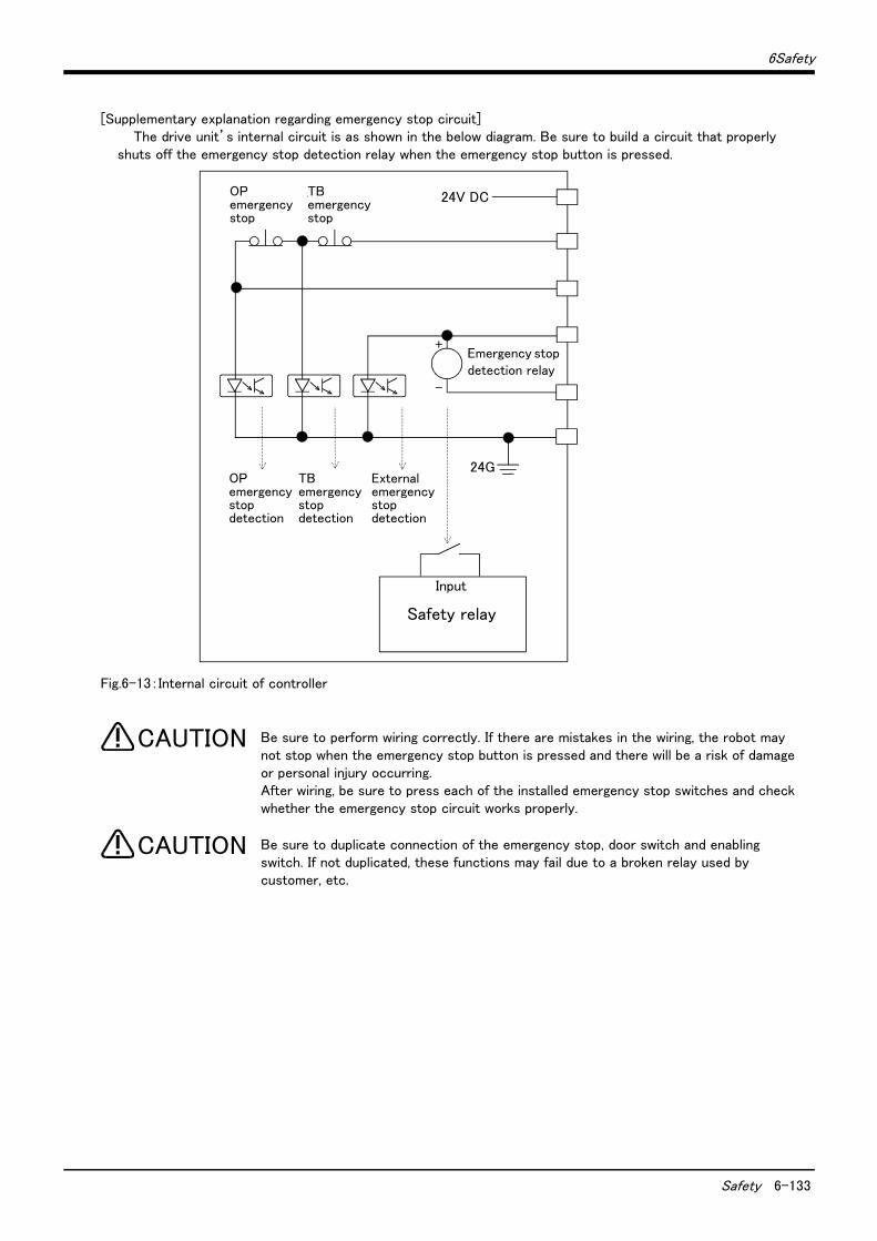
6Safety
Safety 6-133
[Supplementary explanation regarding emergency stop circuit]The drive unit’s internal circuit is as shown in the below diagram. Be sure to build a circuit that properly
shuts off the emergency stop detection relay when the emergency stop button is pressed.
Fig.6-13:Internal circuit of controller
Be sure to perform wiring correctly. If there are mistakes in the wiring, the robot may not stop when the emergency stop button is pressed and there will be a risk of damage or personal injury occurring.After wiring, be sure to press each of the installed emergency stop switches and check whether the emergency stop circuit works properly.
Be sure to duplicate connection of the emergency stop, door switch and enabling switch. If not duplicated, these functions may fail due to a broken relay used by customer, etc.
OP非常停止
非常停止検出リレー
24V DCTB非常停止
+
-
OP非常停止検出
TB非常停止検出
外部非常停止検出
24G
入力
安全リレーSafety relay
Input
Emergency stop detection relay
TB emergency stop
OP emergency stop
OP emergency stop detection
TB emergency stop detection
External emergency stop detection
CAUTION
CAUTION

6-134 Working environment
6Safety
6.2 Working environment
Avoid installation in the following places as the equipment's life and operation will be affected by the ambient environment conditions. When using in the following conditions, the customer must pay special attention to the preventive measures.
(1) Power supply・ Where the voltage fluctuation will exceed the input voltage range.・ Where a momentary power failure exceeding 20ms may occur.・ Where the power capacity cannot be sufficiently secured.
Please use the controller with an input power supply voltage fluctuation rate of 10% or less. In the case of 200 VAC input, for example, if the controller is used with 180 VAC during the day and 220 VAC during the night, turn the servo off once and then on again.
If this is not performed, an excessive regeneration or overvoltage error may occur.
(2) Noise・ Where a surge voltage exceeding 2000V, 5kHz (equivalent to EN61000-4-4) may be applied on the primary volt-age. Near large inverters, high output frequency oscillator, large contactors and welding machines. Static noisemay enter the lines when this product is used near radios or televisions. Keep the robot away from these items.
(3) Temperature and humidity・ Where the atmospheric temperature exceeds 40 degree , lower than 0 degree.・ Where the relative humidity exceeds 85%, lower than 45%, and where dew may condense.・ Where the robot will be subject to direct sunlight or near heat generating sources such as heaters.
(4) Vibration・ Where excessive vibration or impact may be applied. (Use in an environment of 34m/s2 or less during transpor-tation and 5m/s2 or less during operation.)
(5) Installation environment・ Where strong electric fields or magnetic fields are generated.・ Where the installation surface is rough. (Avoid installing the robot on a bumpy or inclined floor.)・ Where there is heavy powder dust and oil mist present.
6.3 Precautions for handling(1) This robot has brakes on J3 axes. The precision of the robot may drop, looseness may occur and the reduction
gears may be damaged if the robot is moved with force with the brakes applied.(2) Avoid moving the robot arm by hand. When unavoidable, gradually move the arm. If moved suddenly, the accu-
racy may drop due to an excessive backlash, or the backed up data may be destroyed.(3) Note that depending on the posture, even when within the movement range, the shaft section could interfere
with the base section. Take care to prevent interference during jog. *1)
(4) The robot arm consists of precision parts such as bearing. Lubricants such as grease are also applied on the moving parts to keep the mechanical accuracy. In a cold start under low temperature or in the first start after being stored for one month or longer, lubricants may not be spread enough. Such condition may lower the positioning accuracy, cause servo and overload alarms, and early wearing of the moving parts. To avoid such situation, perform warm-up operation of the machine at a low speed (at about 20% of normal operation speed). Move the robot arm from the lower to the upper limit of the movable range with the 30 degree joint angle or more for about 10 minutes. After that, speed up the operation gradually. Please use the warm-up operation. (About the details of the warm-up operation, refer to "INSTRUCTION MANUAL/Detailed explanations of functions and operations".)
(5) When the air hoses and cables are used inside the shaft (J3 axis), the grease for cable protection may ooze out or abrasion powders may be generated from the tip of the shaft while the robot is moving. However, move-ments and performance of the robot are not affected. Wipe off the grease or powders as required.
*1) Jog operation refers to operating the robot manually using the teaching pendant.
CAUTION
6Safety
Precautions for handling 6-135
(6) The robot arm and controller must be grounded with 100Ω or less (class D grounding) to secure the noise resistance and to prevent electric shocks.
(7) The items described in these specifications are conditions for carrying out the periodic maintenance and inspections described in the instruction manual.
(8) When using the robot arm on a mobile axis or elevating table, the machine cables enclosed as standard config-uration may break due to the fixed installation specifications. In this case, use "the machine cable extension (for flexed)" factory shipment special specifications or options.
(9) If this robot interferes with the workpiece or peripheral devices during operation, the position may deviate, etc. Take care to prevent interference with the workpiece or peripheral devices during operation.
(10) Do not attach a tape or a label to the robot arm and the controller. If a tape or a label with strong adhesive power, such as a packaging tape, is attached to the coated surfaces of the robot arm and controller, the coated surface may be damaged when such tape or label is peeled off.
(11) If the robot is operated with a heavy load and at a high speed, the surface of the robot arm gets very hot. It would not result in burns, however, it may cause secondary accidents if touched carelessly.
(12) Do not shut down the input power supply to stop the robot. If the power supply is frequently shut down during a heavy load or high-speed operation, the speed reducer may be damaged, backlash may occur, and the pro-gram data may be destroyed.
(13) During the robot's automatic operation, a break is applied to the robot arm when the input power supply is shut down by a power failure, for instance. When a break is applied, the arm may deviate from the operation path predetermined by automatic operation and, as a result, it may interfere with the mechanical stopper depending on the operation at shutdown. In such a case, take an appropriate measure in advance to prevent any dangerous situation from occurring due to the interference between the arm and peripheral devices.Example) Installing a UPS (uninterruptible power supply unit) to the primary power source in order to reduce
interference.
(14) Do not conduct an insulated voltage test. If conducted by mistake, it may result in a breakdown.(15) When the sequencer system becomes large too much, the robot's locus may deteriorate uncommonly. If this
phenomenon occurs, inform to the dealer. And, when it turns out that the system is enlarged in advance, please inform our company.
(16) Fretting may occur on the axis which moving angle or moving distance move minutely, or not moves. Fretting is that the required oil film becomes hard to be formed if the moving angle is small, and wear occurs. The axis which not moved is moving slightly by vibration etc. To make no fretting recommends to move these axes about once every day the 30 degree or more, or the 20mm or more.
(17) The United Nations’ Recommendations on the Transport of Dangerous Goods must be observed for trans-border transportation of lithium batteries by air, sea, and land. The lithium batteries (ER6, Q6BAT) used in Mit-subishi industrial robots contain lithium and fall under the definition.When the lithium batteries are shipped for storage, etc., they will be classified as Class 9: Miscellaneous dan-gerous substances and articles. Please contact your transportation company and must provide appropriate transport safety measures as the customer’s consignor.
(18) If the air supply temperature (primary piping) used for the tool etc. is lower than ambient air temperature, the dew condensation may occur on the coupling or the hose surface.
(19) Collision detection function is valid condition for both of automatic and jog operation at shipping. So, the robot stops immediately if the robot's tool or arm interferes with a peripheral device, minimizing dam-age. Therefore, please use in the valid condition.
(20) When fumigants that contain halogen materials such as fluorine, chlorine, bromine, and iodine are used for dis-infecting and protecting wooden packaging from insects, they cause malfunction when entering our products. Please take necessary precautions to ensure that remaining materials from fumigant do not enter our prod-ucts, or treat packaging with methods other than fumigation (heat method). Additionally, disinfect and protect wood from insects before packing products.
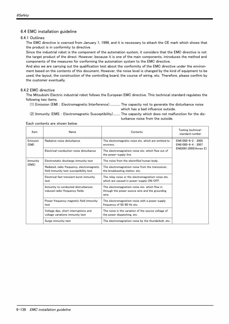
6-136 EMC installation guideline
6Safety
6.4 EMC installation guideline
6.4.1 OutlinesThe EMC directive is coerced from January 1, 1996, and it is necessary to attach the CE mark which shows that the product is in conformity to directive.
Since the industrial robot is the component of the automation system, it considers that the EMC directive is not the target product of the direct. However, because it is one of the main components, introduces the method and components of the measures for conforming the automation system to the EMC directive.
And also we are carrying out the qualification test about the conformity of the EMC directive under the environ-ment based on the contents of this document. However, the noise level is changed by the kind of equipment to be used, the layout, the construction of the controlling board, the course of wiring, etc. Therefore, please confirm by the customer eventually.
6.4.2 EMC directiveThe Mitsubishi Electric industrial robot follows the European EMC directive. This technical standard regulates the following two items.
(1) Emission (EMI : Electromagnetic Interference) ............. The capacity not to generate the disturbance noise which has a bad influence outside.
(2) Immunity (EMS : Electromagnetic Susceptibility)......... The capacity which does not malfunction for the dis-turbance noise from the outside.
Each contents are shown below.
Item Name ContentsTesting technical-
standard number
Emission(EMI)
Radiative noise disturbance The electromagnetic noise etc. which are emitted to environs.
EN61000-6-2 : 2005EN61000-6-4 : 2007
EN62061:2005(Annex E)Electrical-conduction noise disturbance The electromagnetism noise etc. which flow out of
the power-supply line.
Immunity
(EMS)
Electrostatic discharge immunity test The noise from the electrified human body.
Radiated, radio-frequency, electromagnetic
field immunity test susceptibility test
The electromagnetism noise from the transceiver,
the broadcasting station, etc.
Electrical fast transient burst immunity
test
The relay noise or the electromagnetism noise etc.
which are caused in power-supply ON/OFF.
Immunity to conducted distrurbances
induced radio-frequency fields
The electromagnetism noise etc. which flow in
through the power source wire and the grounding
wire.
Power frequency magnetic field immunity
test
The electromagnetism noise with a power supply
frequency of 50/60 Hz etc.
Voltage dips, short interruptions and
voltage variations immunity test
The noise in the variation of the source voltage of
the power dispatching, etc.
Surge immunity test The electromagnetism noise by the thunderbolt, etc.

6Safety
EMC installation guideline 6-137
6.4.3 EMC measuresThere are mainly following items in the EMC measures.
(1) Store into the sealed metal board.(2) Grounding all the conductor that have floated electrically (makes the impedance low).(3) Wiring so that the power source wire and signal wire are separated.(4) Use the shield cable for the cable which wired outside of the metal board.(5) Install the noise filter.
To suppress the noise emitted out of the board, be careful of the following item.
(1) Ensure grounding of the equipment.(2) Use the shield cable.(3) Separate the metal board electrically. Narrows the distance/hole.
The strength of electromagnetic noise emitted to environment is changed a lot by the shielding efficiency of cable and the distance of metal board, so it should be careful.
6.4.4 Component parts for EMC measures(1) Ferrite core
The ferrite core is mounted by the plastics case as one. It can attach by the one-touch, without cutting the cable. This has the effect in the common-mode noise. The measures against the noise are made not influential in the quality of the signal.
There are the following as an example.
(2) Line noise filterType : FR-BLF (Mitsubishi Electric Corp.)
Maker: SEIWA ELECTRIC MFG. Co.,Ltd.
Type
Outside dimension (mm) Diameter of the
adaptation cable [max] (mm)A B C D
E04SR401938 61 38 19 40 19.0
E04SR301334 39 34 13 30 13.0
Maker: TAKACHI ELECTRONICS ENCLOSURE CO., LTD.
Type
Outside dimension (mm) Diameter of the
adaptation cable
[max] (mm)A B C D
TFT-274015S 43.8 27.4 20.7 - φ26.5
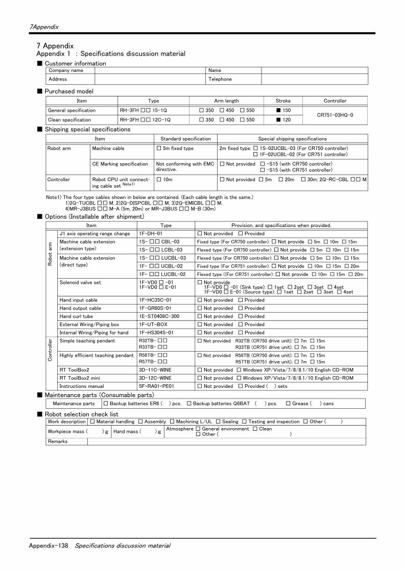
Appendix-138 Specifications discussion material
7Appendix
7 AppendixAppendix 1 : Specifications discussion material
■ Customer information
■ Purchased model
■ Shipping special specifications
■ Options (Installable after shipment)
■ Maintenance parts (Consumable parts)
■ Robot selection check list
Company name Name
Address Telephone
Item Type Arm length Stroke Controller
General specification RH-3FH □□ 15-1Q □ 350 □ 450 □ 550 ■ 150CR751-03HQ-0
Clean specification RH-3FH □□ 12C-1Q □ 350 □ 450 □ 550 ■ 120
Item Standard specification Special shipping specifications
Robot arm Machine cable □ 5m fixed type 2m fixed type: □ 1S-02UCBL-03 (For CR750 controller)□ 1F-02UCBL-02 (For CR751 controller)
CE Marking specification Not conforming with EMC directive.
□ Not provided □ -S15 (with CR750 controller)□ -S15 (with CR751 controller)
Controller Robot CPU unit connect-ing cable set Note1)
Note1) The four type cables shown in below are contained. (Each cable length is the same.)1)2Q-TUCBL □□ M, 2)2Q-DISPCBL □□ M, 3)2Q-EMICBL □□ M,4)MR-J3BUS □□ M-A (5m, 20m) or MR-J3BUS □□ M-B (30m)
□ 10m □ Not provided □ 5m □ 20m □ 30m: 2Q-RC-CBL □□ M
Item Type Provision, and specifications when provided.
Robo
t ar
m
J1 axis operating range change 1F-DH-01 □ Not provided □ Provided
Machine cable extension
(extension type)
1S- □□ CBL-03 Fixed type (For CR750 controller): □ Not provide □ 5m □ 10m □ 15m
1S- □□ LCBL-03 Flexed type (For CR750 controller): □ Not provide □ 5m □ 10m □ 15m
Machine cable extension
(direct type)
1S- □□ LUCBL-03 Flexed type (For CR750 controller): □ Not provide □ 5m □ 10m □ 15m
1F- □□ UCBL-02 Fixed type (For CR751 controller): □ Not provide □ 10m □ 15m □ 20m
1F- □□ LUCBL-02 Flexed type ((For CR751 controller): □ Not provide □ 10m □ 15m □ 20m
Solenoid valve set 1F-VD0 □ -011F-VD0 □ E-01
□ Not provide1F-VD0 □ -01 (Sink type): □ 1set □ 2set □ 3set □ 4set1F-VD0 □ E-01 (Source type): □ 1set □ 2set □ 3set □ 4set
Hand input cable 1F-HC35C-01 □ Not provided □ Provided
Hand output cable 1F-GR60S-01 □ Not provided □ Provided
Hand curl tube 1E-ST0408C-300 □ Not provided □ Provided
External Wiring/Piping box 1F-UT-BOX □ Not provided □ Provided
Internal Wiring/Piping for hand 1F-HS304S-01 □ Not provided □ Provided
Contr
olle
r Simple teaching pendant R32TB- □□
R33TB- □□□ Not provided R32TB (CR750 drive unit): □ 7m □ 15m
R33TB (CR751 drive unit): □ 7m □ 15m
Highly efficient teaching pendant R56TB- □□
R57TB- □□□ Not provided R56TB (CR750 drive unit): □ 7m □ 15m
R57TB (CR751 drive unit): □ 7m □ 15m
RT ToolBox2 3D-11C-WINE □ Not provided □ Windows XP/Vista/7/8/8.1/10 English CD-ROM
RT ToolBox2 mini 3D-12C-WINE □ Not provided □ Windows XP/Vista/7/8/8.1/10 English CD-ROM
Instructions manual 5F-RA01-PE01 □ Not provided □ Provided ( ) sets
Maintenance parts □ Backup batteries ER6 ( ) pcs. □ Backup batteries Q6BAT ( ) pcs. □ Grease ( ) cans
Work description □ Material handling □ Assembly □ Machining L/UL □ Sealing □ Testing and inspection □ Other ( )
Workpiece mass ( ) g Hand mass ( ) g Atmosphere □ General environment □ Clean□ Other ( )
Remarks
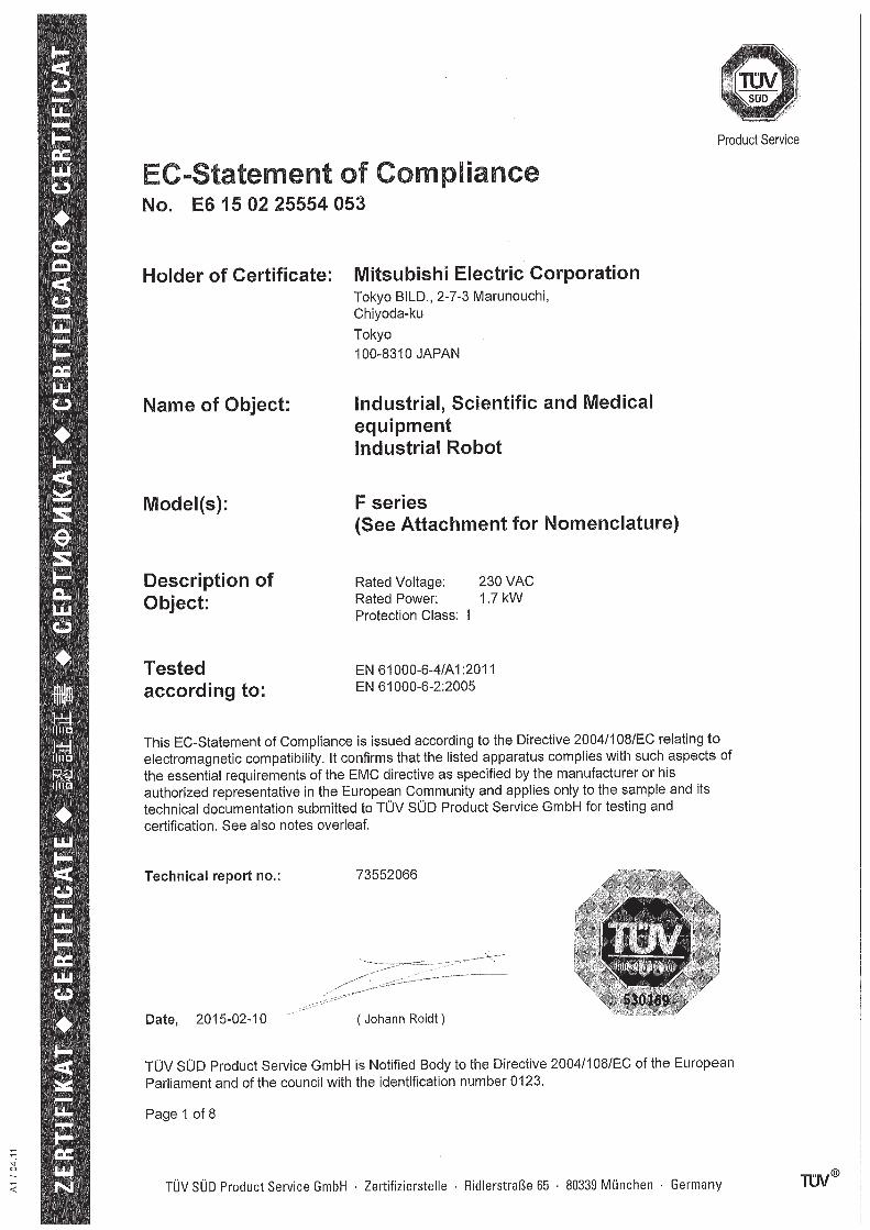

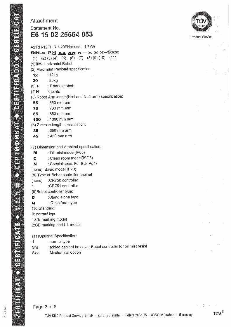

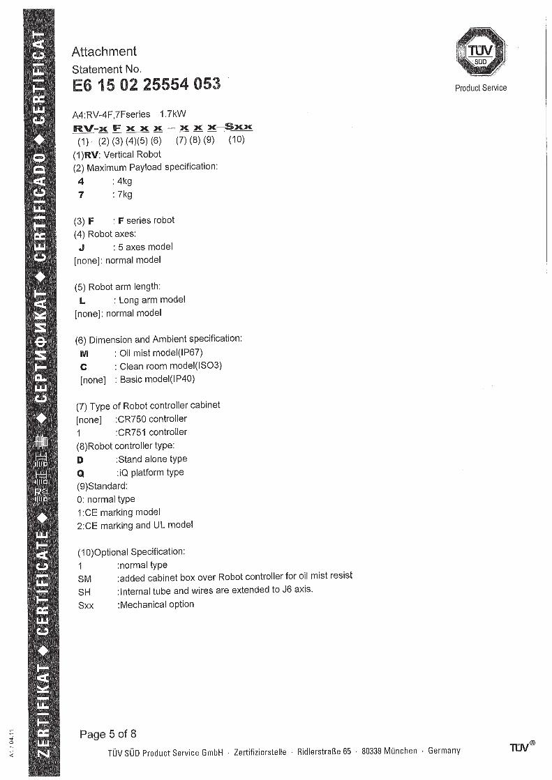
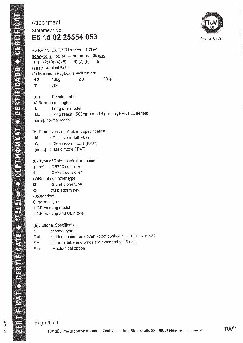
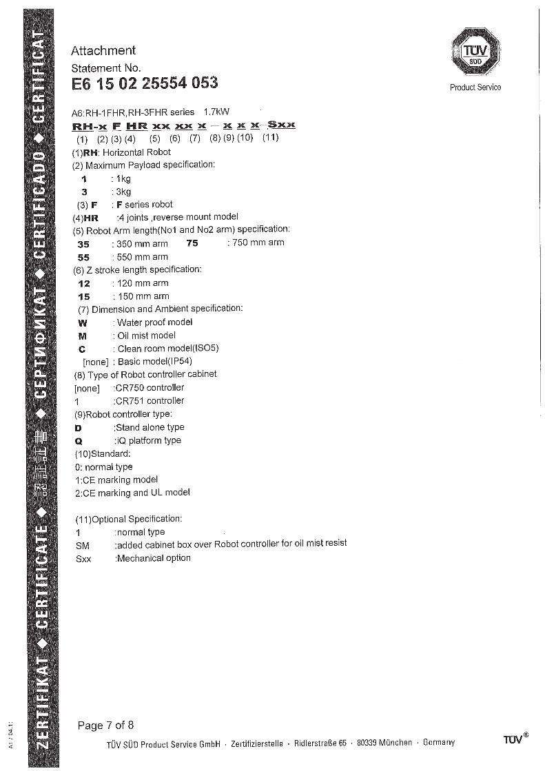
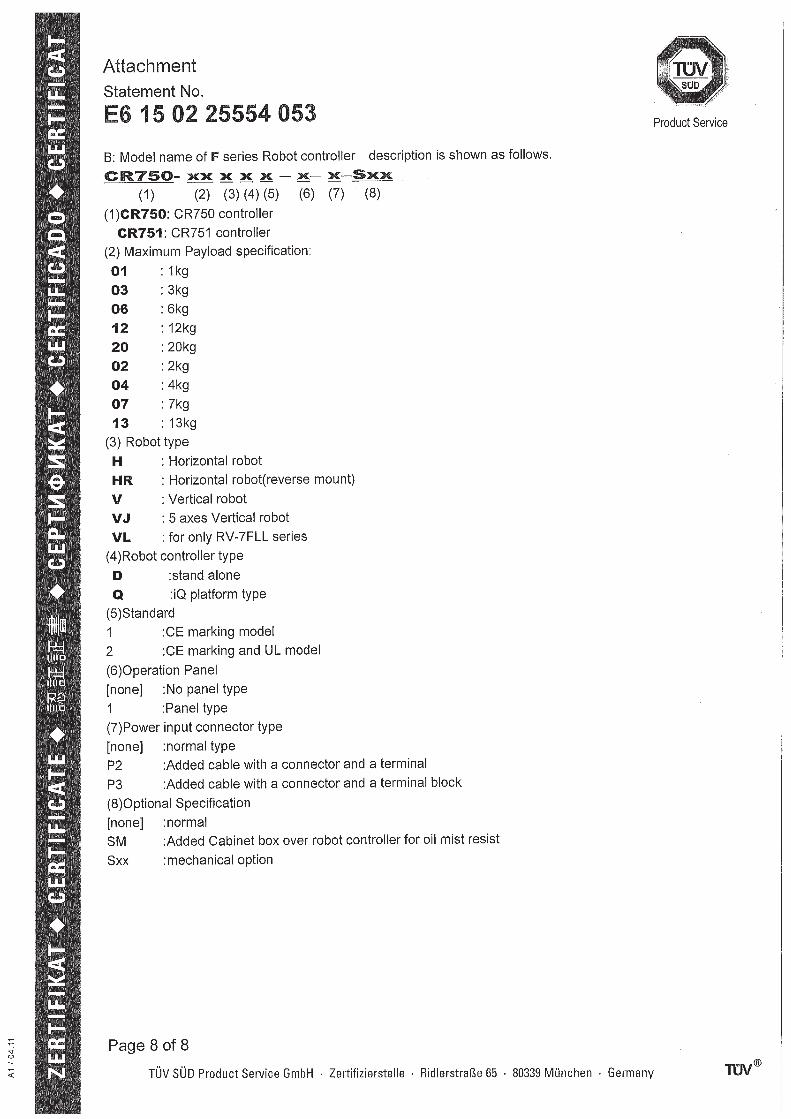


HEAD OFFICE: TOKYO BUILDING, 2-7-3, MARUNOUCHI, CHIYODA-KU, TOKYO 100-8310, JAPANNAGOYA WORKS: 5-1-14, YADA-MINAMI, HIGASHI-KU NAGOYA 461-8670, JAPANAuthorised representative:
Mitsubishi Electric Europe B.V. FA - European Business GroupMitsubishi-Electric-Platz 1, D-40882 Ratingen, GermanyTel: +49(0)2102-4860
Apr., 2019 MEE Printed in Japan on recycled paper. Specifications are subject to change without notice.