Embed Size (px)
Citation preview
i
RGB LED Color Mixing Controller
Previously known as:
High Frequency Measurement Device
Final Report
Fall Semester, 2007
by
Derek Hall
Prepared to partially fulfill the requirements for ECE402
i
Abstract
With LED lighting becoming increasingly popular each year, more and more
opportunities surround these applications. Color Kinetics and other companies and
individuals use LED controllers for residential and commercial lighting solutions.
Presently, many commercial off the shelf controllers incorporate little functionality and
offer little flexibility. Having justified the need and application, a red, green, and blue
color mixing LED controller was designed.
The design centered on programmable system on chips donated from Cypress.
Originally, the platform was developed around Cypress’ wireless development kit.
However, after complications and due to constraints, the design had to exhibit flexibility
and was transferred to an evaluation board, losing the wireless capability but enabling
USB communication with the device.
Project goals centered on user configurable mixing of a bank of red, green, and blue
LEDs in order to achieve a desired color. As part of this requirement, a GUI was
necessitated and also demonstrated features such as color sequencing and strobing, and
was even expanded to color fading during these user configured color sequences.
A unique USB HID device was instantiated on the PSoC side, and the requisite code to
enable communication with this device via the GUI was also developed. Finally, three
pulse width modulators are used to control the red, green, and blue LEDs. The PSoC
main program uses data transmitted over USB to vary the period of the PWMs in real
time based on user interaction with the GUI.
Even with these successes, there are areas in need of future improvements. Increased
functionality such as saving and loading sequences, calibration of LED luminosities for
color mixing, and the implementation of secure wireless communication are all possible.
ii
Table of Contents
Abstract .............................................................................................................................................i
Table of Contents .............................................................................................................................ii
Table of Figures ...............................................................................................................................iii
Introduction..................................................................................................................................... 1
Background...................................................................................................................................... 2
USB .............................................................................................................................. 2
USB 2.0 .......................................................................................................... 6
Wireless USB ..................................................................................................... 7
Security...................................................................................................................................... 10
Design ............................................................................................................................................ 11
PSoC........................................................................................................................................... 12
Device Communication ............................................................................................................. 14
GUI............................................................................................................................................. 15
Conclusions and Future Work ....................................................................................................... 16
Acknowledgements ....................................................................................................................... 17
References..................................................................................................................................... 18
Appendix........................................................................................................................................ 19
Budget ....................................................................................................................................... 19

iii
Table of Figures
Figure 2 Power consumption by RF band ........................................................................... 9
Figure 1 WUSB and UWB niche .......................................................................................... 1
1
Introduction
Having wrapped up the desired goals of the High Frequency Measurement Device, the
project set sights for new challenges. In this search, the growing number of applications
for LED’s became apparent, in addition to one specific area that would prove to be the
focus of this project.
LED’s have seen tremendous growth in popularity over the past few years, and rightly
so. One large reason is the increased efficiency when compared to traditional
incandescent light bulbs. In conjunction with a strong social push for energy reduction
and cost savings, LED’s have ridden this wave and are becoming more and more popular
in both residential and commercial settings. Not only are LED’s capable of higher
lumens per Watt, but they have the added benefit of a longer lifetime. Estimated time
to failures for LED’s are often more than 100,000 hours, a figure that dwarfs both
incandescent bulbs (2,000) and fluorescent lighting (30,000) [1]. Another advantage
held over their counterparts is that, being a solid state device, LED’s are not damaged as
easily from external shock.
As a result of these features, LED’s are commonly used in traffic lights, lamps, displays,
remote controls, and architectural lighting. Companies such as Color Kinetics specialize
in commercial and residential LED lighting. Many LED controllers are commercially
available for individuals and businesses to use in conjunction with LED light sources. A
problem was recognized that the vast majority of these controllers offer very limited
functionality and offer little ease of use for the growing number of individuals seeking to
cheaply implement their own LED lighting schemes. Recognizing this fact, the goal of
this project was to create a red, green, and blue LED color mixing controller (RGB LED
Color Mixing Controller).
2
Drawing from the limited functionality and difficulty of use from current offerings,
several project goals became clear. First, it was desired to make a controller that could
be utilized by any person regardless of technical background. Expanding on this idea,
the concept of automating an LED controller with the use of a graphical interface was
identified as a key component to solving the current shortcomings found in controllers.
The next area identified as needing improvement was the ability to control colors.
Typically, LED controllers are designed to work with discrete colors or a very limited
mixture of colors. How could this be improved? Quite obviously, the user needed more
options. A controller designed for use with three LED color sources; red, green, and
blue, should be able to generate any color from the mixing of these three sources.
Finally, in order the interface the controller and the GUI, a common communication
standard needed to be implemented to accomplish this. The following Background
section provides a historical basis for selecting the chosen standard and details the
technical specifics which had to be addressed during implementation. Following the
selection of this standard and a microcontroller platform, the hardware and software
design processes began and are outlined in the following Design section.
Background
USB
By the mid 1990’s there was a growing myriad of peripheral devices: scanners, printers,
PDA’s, mouse devices, keyboards, gamepads and joysticks, often times each with their
own plug that served essentially the same task of interfacing, but these plugs were not
interchangeable. Frequently, it would require complicated installation procedures,
software, and drivers to be able to communicate with the external devices. While RS-
3
232 and GPIB had enjoyed great successes, the standards were no longer keeping up
with technology and neither had been universally adopted. A new, faster and easier
way to interface devices was needed, a one cable approach and a universal bus.
In 1995 a consortium of industry leaders formed the USB Implementers Forum (USB-IF).
With participation from prominent industry members, the creation and adoption of a
universal serial bus (USB) was possible. The goal was to retire the legacy serial and
parallel ports, which were not standardized and required a great number of drivers to
be developed and maintained [2]. The resultant standard would drastically change the
computer world.
Within a matter of years the majority of peripheral devices had USB capability and
computers could be built with only two or three different kinds of plugs. Previously,
there had simply been too many competing plug designs for peripheral
communications. Not only was this confusing for end users, but it placed an additional
burden on design to accommodate for the multitude of unique plugs if the device was
to be compatible with a wide demographic.
A maximum number of 127 devices can be connected to the serial bus by a hub
topology with a maximum cable length of five meters. The specification allows for host
based networking. This means that peripherals must connect to a computer or some
such host, but, for example, a camera will not be able to talk to another camera via USB.
Devices connected to USB are known as functions and are connected in serial with hubs
(either additional hubs or to the host controller hub). Once a device is first connected,
the host enumerates and recognizes the device and loads any device driver that is
needed [2]. When a device or an additional hub is attached, it is given a unique seven
bit address on the bus by the host controller. USB uses a “speak when spoken to”
protocol over its four wires, such that no function can transfer any data on the bus
without an explicit request from the controller. Two of the wires provide power, while
4
one twisted pair serves the communication. The protocol utilizes a non-return-to-zero
inverted (NRZI) system for encoding data sent between a host controller and multiple
peripherals.
There are four types of transfers that can take place: control, interrupt, isochronous,
and bulk. Control transfers are primarily used for status and command operations,
while interrupts are initiated by devices to request an action from the host. Isochronous
transfers represent a guaranteed bandwidth and are used to transmit data that is time
critical. Bulk transfers, on the other hand, can use all available bandwidth but are not
time critical transactions. Transfers over the bus are done with packets, and traffic is
regulated using frames based of a 1 kHz clock that also provides synchronization
between isochronous transfers and the bus.
Devices attaching to the bus can be uniquely custom, requiring a custom device driver,
or they may belong to a specific device class. A device class describes a group of devices
or interfaces with similar attributes and services and defines requirements for the
related group. This allows for a single device driver to be adapted across a broad range
of devices falling into the class. This reduces the number of drivers that must be
maintained, and allows these adaptive drivers to be developed by operating system and
third party software vendors in addition to manufacturers supporting multiple products
[3]. Class information is used to identify a driver for the device’s interface connectivity
and the capability provided by the interface. Two devices are typically placed in the
same class if they provide or consume data streams with similar formats, or
communicate with a host system by a similar means [3]. These classes range from
audio, battery charging, cable and connector, communications, common class, human
interface device (HID), imaging, mass storage, printer, smart card, test and
measurement, and beyond. Example devices found in the HID class are mice,
keyboards, and tablets. The mass storage class was initially intended for traditional
5
magnetic and optical drives, but has seen widespread use in portable USB hard drives,
thumb-drives, and mp3 players.
As a result of the primary goal for the creation of USB (creating a standard bus for
interfacing of peripherals) and due to the relatively slow data rates required by
peripherals during this period, the first USB1.0 release specified a fairly low transfer rate
of 1.5Mbps. In the USB1.1 release, the rate was increased to 12Mbps. However, in
these early versions of USB, this transfer rate would severely limit the use of USB with
data intensive peripherals such as external hard drives and video. An additional
negative is the fact that USB up to this point limits a device’s use of the bandwidth to
50% [4]. Compared to FireWire’s rate of 400Mbps, which was also released in the ‘90’s,
USB was severely disadvantaged and relegated to lower bandwidth devices.
Also with the release of USB1.1, numerous clarifications, enhancements, and resolutions
(bug fixes) were made to the original 1.0 specification. Among these was the creation of
an Interrupt Out transfer type, which eliminates bandwidth consumed by implementing
force-feedback applications with isochronous transfers, for example from a device that
requires periodic data from the host [5]. In addition to this, compliance test and test
methods were more clearly defined.
Several key features arrived with the USB standard. Among the primary advantages
offered, the interface allowed for true implementation of Plug and Play (PnP); the
attachment of a device, nominally a peripheral, without requiring reconfiguration or
manual installation of drivers. The capability to plug in a device and be automatically
detected and configured means that a new device can immediately be ready for use.
Another important aspect that was introduced was the ability to hot-swap devices; the
ability to connect and disconnect devices without requiring a reboot. In addition to this,
while designing USB it was also noticed that some devices require a small amount of
power. Recognizing the hassle of running additional cables to AC adapters in these
6
cases, USB is able to provide power to these devices. Up to half an amp can be supplied
at five volts. Some devices can even recharge their batteries via USB. It can typically be
assumed that devices requiring significantly larger amounts of power will have their own
power supply.
Plugs for USB were designed with lessons learned from the traditional serial and parallel
plugs that the new interface would replace. The connectors are designed to be robust,
without the pins that were previously common, with the connector being protected by a
metal sheath in addition to a plastic sheath protecting the electrical contacts. The most
important part though, is that the connectors are cheap to manufacture. Two plugs,
series A and series B, were specified. Series A connectors are used with devices which
have a permanently attached external cable. Series B connectors are utilized in cases
when the USB cabling is detached. The electrical contacts on series B are also recessed.
With newer motherboards being shipped with USB capability, and the support of Intel
which gave USB popularity in the PC market that FireWire and similar standards could
never achieve, there was very low cost in adding USB functionality to existing systems.
With a compatible motherboard, only a USB port on the order of a few dollars is needed
and can be added by a USB PCI-based add-in card for example. In addition to this, there
are numerous connectors for USB to RS-232 and other such a priori standards. In
system design, relatively inexpensive microcontrollers with built in USB functionality can
be used.
USB 2.0
Since USB had not been designed as a high speed external bus, it was generally thought
that USB and the much faster FireWire complemented each other and could coexist. By
the late 1990’s however, Apple began to leverage their intellectual property and the
7
high data rates that FireWire was capable of. At this time, Apple began asking licensees
for a $1/per port fee [6]. This fee, although seemingly small, meant that a device such
as a FireWire enabled hard drive using two connectors would cost $2 more than
previously. This effect quickly ballooned into large sums of money for manufacturers
shipping large quantities of devices, and the effect was similarly felt on smaller
companies and startups with even thinner profit margins.
Led by Intel, the USB Implementers Forum (USB-IF) proceeded to work on a newer
version of USB that could compete with the much higher transfer rates of FireWire.
Even though Apple reduced their license fee by over half around this time, research
continued. The result in 2000 was USB 2.0 (High Speed USB) and featured an impressive
top end of 480Mbps. This higher transfer rate is the only significant change from the
USB 1.1 specification, and USB 2.0 is backwards compatible with previous versions. As a
result, USB 2.0 hubs must allow for different signaling rates on its ports.
The new USB standard represented better than a 40x increase over Full Speed USB and,
on paper, was 80Mbps faster than F400. With the release of F800 though, USB 2.0 was
and remains severely disadvantaged in terms of transfer rates, and FireWire remains a
favorite choice among data intensive applications such as external hard drives and
digital multimedia.
Wireless USB
With 3.5 billion USB interfaces expected to be in place by 2006, USB has become the
world’s most successful interface[7]. Leveraging such a large installed base, the USB-IF
set out to further extend the standards broad reach.
In 2006, Wireless USB (WUSB) was introduced. Based on WiMedia’s ultra wide-band
radio platform (UWB), the standard is currently capable of bandwidths of 110Mbps at a
8
distance of 10m and 480Mbps at a distance of 3m. The architecture is also scaleable up
to 1Gbps and beyond [7].
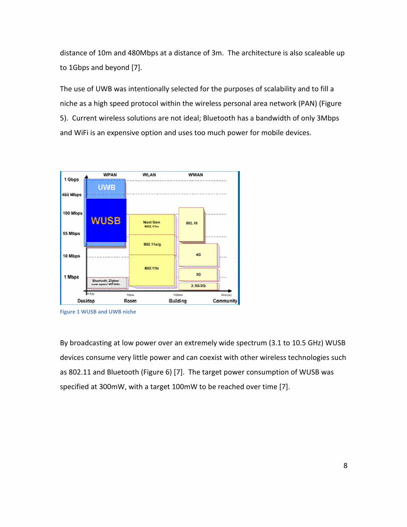
The use of UWB was intentionally selected for the purposes of scalability and to fill a
niche as a high speed protocol within the wireless personal area network (PAN) (Figure
5). Current wireless solutions are not ideal; Bluetooth has a bandwidth of only 3Mbps
and WiFi is an expensive option and uses too much power for mobile devices.
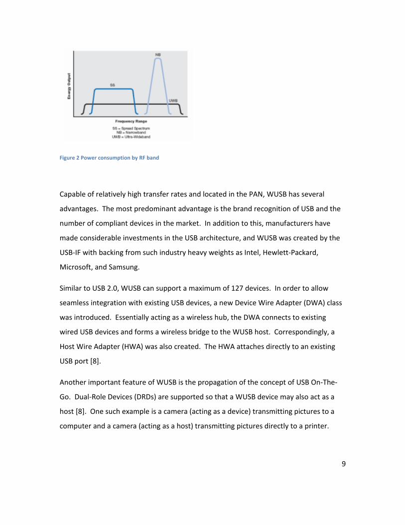
By broadcasting at low power over an extremely wide spectrum (3.1 to 10.5 GHz) WUSB
devices consume very little power and can coexist with other wireless technologies such
as 802.11 and Bluetooth (Figure 6) [7]. The target power consumption of WUSB was
specified at 300mW, with a target 100mW to be reached over time [7].
Figure 1 WUSB and UWB niche
9
Figure 2 Power consumption by RF band
Capable of relatively high transfer rates and located in the PAN, WUSB has several
advantages. The most predominant advantage is the brand recognition of USB and the
number of compliant devices in the market. In addition to this, manufacturers have
made considerable investments in the USB architecture, and WUSB was created by the
USB-IF with backing from such industry heavy weights as Intel, Hewlett-Packard,
Microsoft, and Samsung.
Similar to USB 2.0, WUSB can support a maximum of 127 devices. In order to allow
seamless integration with existing USB devices, a new Device Wire Adapter (DWA) class
was introduced. Essentially acting as a wireless hub, the DWA connects to existing
wired USB devices and forms a wireless bridge to the WUSB host. Correspondingly, a
Host Wire Adapter (HWA) was also created. The HWA attaches directly to an existing
USB port [8].
Another important feature of WUSB is the propagation of the concept of USB On-The-
Go. Dual-Role Devices (DRDs) are supported so that a WUSB device may also act as a
host [8]. One such example is a camera (acting as a device) transmitting pictures to a
computer and a camera (acting as a host) transmitting pictures directly to a printer.
10
Security
One goal of the WUSB standard was to make wireless communications as secure as
wired USB. Due to the inherent nature of wireless communications and the lack of a
direct path, two major steps are taken: association and encryption.
Association is the unique recognition between a host and a specific device. This is
accomplished by a one-time wired connection with the host or by numeric association.
During wired association, the device and host exchange a unique 384-bit identifier
known as a “connection context”. Numeric association consists of the user verifying
that hex codes brought up by both the device and the host are the same upon first time
use. This latter method is less secure, and due to the wireless nature of the
communication it can be easily eavesdropped. It is hoped that the limited range of
WUSB will help to counter this threat, and users looking for the most secure option
should always use wired association.
Encryption is implemented with an AES 128-bit algorithm. During each session, data is
encrypted using a session key derived from the aforementioned connection context.
While these features do make WUSB exceptionally secure for a wireless standard, USB
devices themselves are not inherently “safe”. Viruses, malicious software (including
keystroke loggers), data theft, all can occur intentionally or unintentionally through the
connection of a USB device. These issues are not limited solely to USB and also affect
FireWire.
These problems are compounded by the fact that administrator privileges are not
needed to use USB devices, and USB devices cannot be managed using Group Policy [9].
This is especially tricky in large organizations, where someone could easily obtain access
to a USB port via social engineering or other means. Full blown exploits such as DebPloit
can even be utilized for gaining administrative privileges through execution of
applications intentionally supplied by a malicious USB device [10].
11
With the popularity enjoyed by USB in the commercial arena, it clearly had to be the
standard of choice. It would make no sense to design the RGB LED Color Mixing
Controller around some other serial standard, and the nature of this controller definitely
does not necessitate the speed of FireWire.
As luck would turn out, the Engineering Research Center lab had previously been
donated wireless USB and wired USB solutions from Cypress for use in prior design
projects. The wired USB evaluation kit included an 8-bit programmable system on
chip(PSoC) and USB port in addition to other features. The WUSB included board for a
transmitter and receiver, both housing two 8-bit PSoCs chained together, and a USB
port.
The wireless kit was chosen to be the primary platform for the controller design, as this
would allow more options in placing LED lighting in a commercial realm.
Design
In order to implement the controller and GUI designs, a computer would need to talk to
the transmitter over wired USB. On the transmitter board, the PSoC and radio module
would then relay commands to the radio module on the receiver. The PSoC on the
receiver board would need to interpret these signals and implement the color mixing of
the LED’s. From this logical overview, the design can be broken into three steps: PSoC,
device communication, and GUI.
12
PSoC
The first priority in dealing with the wireless development kit was to verify
communication of the boards, and then to proceed with the LED controller design.
Following numerous tutorials, example communication between the two boards was
demonstrated, and investigation of the controller design began.
In order to mix the red, green, and blue LEDs to obtain desired colors, the luminosity of
each color must be adjustable. The easiest way to accomplish this is by varying the duty
cycle. Pulse width modulation is a standard technique used to modulate the duty cycle
and control power sent to a load. In order to control red, green, and blue LEDs
discretely, a separate pulse width modulator must be instantiated to send each signal.
A module within the Cypress PSoC was utilized to instantiate these PWMs and set up
output pins for the red, green, and blue signals. By utilizing an 8-bit PWM, 256 levels of
color for red, green, and blue can be accomplished. Theoretically, this should make 24
bits of total color resolution available to the user and create 16,777,216 colors.
No design is without its challenges however. At this point in the design, device
intercommunication could no longer be verified between the boards. After
troubleshooting, a faulty radio module adapter was identified as the cause. Also at this
point, questions were arising as to how communication between a computer and the
transmitter over wired USB could be accomplished. After discussing the faulty radio
module and these other growing concerns with technical support, a number of
detrimental discoveries were made.
In order to implement USB communication between the board and a host, a separate
human interface device (HID) bridge was necessary. This HID bridge can only be
functionalized through the use of Cypress’ enCore chip. While the wireless
development kit came with several pre-defined HID bridges, such as a mouse, keyboard,
and gamepad, design for other custom wireless applications would necessitate
13
programming a one-time-programmable enCore chip with the custom USB driver
information. To make matters worse, the cost for an enCore development kit is
upwards of $750 and well out of range of the project’s $100 budget. Additionally, there
was not enough time in order to both secure the donation of the new kit and learn a
new development kit in order to design yet another chip. The final disappointing
discovery was the fact that Cypress’ wireless development kit does not use WUSB, but
rather wired USB is utilized to communicate to the transceiver while the radios use a
2.4-GHz protocol unique to Cypress.
As a result of these discoveries and due to time constraints, the RGB LED Color Mixing
Controller design changed platforms to the PSoC evaluation board from Cypress that the
ERC lab had on hand. Functionally, the design changed very little as the GUI still
required USB communication with the evaluation board that housed the PSoC.
Shifting the existing PSoC design to the new chip on the evaluation board, the three
PWMs were kept and a USB module was added. The USB module configures the pins on
the evaluation board for the required communication, and the designer is allowed to set
every technical detail concerning end-points, power required, transfer speeds, and
report length.
In order for ease of design and comparison to existing examples and tutorials, a report
length of one byte was utilized. Having these details set up, the PSoC was designed to
poll the line for communication from the host and recognize data transmission with a
flag. This allowed every transaction to be flagged with an interrupt and loaded into
register A on the PSoC. Upon receiving the data, the PSoC would then need to make a
determination as to which PWM the data was intended for. The device carries this
routine out in an infinite loop: wait for host communication, flag data, route data,
update PWM, and wait for host communication. Upon registering a data transaction
and moving the data to the aforementioned register, a routine programmed in assembly
is called to update the period of the necessary PWM with the newly read information.
14
As a result of this scheme, a trade off had to be made in order to accomplish data
routing. The first two bits are utilized to embed data identifying which PWM the signal
is meant for. Namely, xxxxxx01 corresponds to red information, xxxxxx10 corresponds
to green information, and xxxxxx11 corresponds to blue information. The fourth state
was not utilized, and could easily be leveraged to implement some additional feature.
As a result, some color resolution was technically lost; however, being the two least
significant bits, there are virtually no functional differences as observed by the human
eye.
Device Communication
Device communication was accomplished by customizing a USB driver and embedding
the necessary code on the GUI side to recognize and interact with the PSoC’s uniquely
configured USB module.
As a functional overview, the GUI must talk to the Windows application programming
interface (API) in C. Once this is accomplished, the USB code in the GUI has access to
ports and is functionally capable of communication. Upon recognizing and instantiating
a device, the GUI-side code then monitors the USB reports for reading and writing data.
Connection to the USB device is checked for and verified every 300 milliseconds, and
data read reports are given 80 milliseconds for a successful read before the host sends a
no acknowledge. Writing is accomplished by mapping a data-write command to the
ports that were previously mapped by the USB-Windows API code. The GUI-side code
checks for an empty buffer and a clear line before writing data.
On the PSoC side, this information is then read in as described above with the main C
file. The actual write data is then held in the A register and the hardware routine
programmed in assembly changes the period of the corresponding PWM according to
the data read.
15
GUI
The primary goals of the GUI were to allow a user to select varying levels of red, green,
and blue colors and to also allow for the sequencing of selected colors over user
configured durations. This was accomplished in Visual Basic with the incorporation of a
form and the underlying code, plus the aforementioned USB code modules to handle
communication.
Three sliders were used in order to create the controls for selecting a red, green, and
blue combination. The maximum and minimum of these sliders was set to correspond
with the 256 levels of the 8-bit PWMs on the PSoC. Data resulting from these sliders is
contained in byte format, and program logic was developed to mask these values with
the previously discussed addressing code for data direction. Data is then sent to the
controller with any change of slider value for each color.
Additionally, a solid round object representing a RGB LED was incorporated into the GUI
design, both for user functionality and testing of the design. This “GUI LED” reads the
red, green, and blue byte values that are sent to the controller and updates the display
on the GUI, reflecting what end color the combined color mixture should be.
Following these basic accomplishments, additional functionality was added. Strobing of
the LEDs was accomplished by rapidly sending on and off signals for each applicable
color, and arrays are capable of storing sequences of user configured colors in addition
to durations for each color. Multiple clocks on the GUI side were utilized to control
these durations and write the appropriate color data when the necessary duration is
expired. Additionally, the user was given the option to loop sequences.
The power of the GUI lies in the processing power that is available to implement
features for the controller. This also serves to free up resources on the PSoC for other
16
tasks. All of the above steps represent a logical build up of functionality, and requires
simply expanding existing logic and code. Having met all the specified requirements, a
more complex feature was added and demonstrated the power of this GUI-side
processing.
Color fading was successfully established for gradual transitions of color sequences by
adding logic to determine whether the duty cycle of a given color needed to be
gradually increased or decreased in order to transition to the next sequence. This
feature was able to be fully integrated with the existing functionality of sequencing and
looping, and exhibits how easily LED effects can be generated from a GUI controlled RGB
LED Color Mixing Controller.
Conclusions and Future Work
A RGB LED Color Mixing Controller with GUI control via USB was successfully realized.
Every GUI and LED controller goal was met and successfully demonstrated, and the basis
for commercial control of multiple red, green, and blue LED lighting strips has been
demonstrated. However, there are many improvements that could and should be
implemented before the device could be considered commercially ready.
Firstly, colors do not precisely mix. This is a direct result of the differing luminosities
output by the red, green, and blue LEDs. In addition to this, it is likely that the turn on
voltage of each diode is different and the luminosity vs. current curves are not perfectly
correlated between the three colored LEDs. In the future, some calibration scheme
should be implemented in order to achieve richer color mixing.
17
Secondly, there are many more user features that could be added. These include saving
and loading files, configurable durations of fading, and temperature sensing on the PSoC
side. In addition to this, the controller should be made to handle high power LEDs.
Finally, it would be worthwhile to implement wireless communication between the GUI
and the controller. However, I don’t believe the Cypress wireless development kit is a
viable option for this. Security is of high concern for the design, and as such a standard
such as ZigBee or WUSB which incorporates encryption should be implemented.
However, these standard will be substantially more expensive than the more common
2.4GHz protocols utilized by Cypress, ChipCon, and TI wireless microcontrollers. These
protocols are much simpler; however, if this was determined to be the only option, I
would recommend a product such as the TI eZ430-RF2500. This is the wireless version
of the TI microcontroller that is now being used in ECE251 and, according to TI technical
support, should necessitate on the order of a mere six API calls to implement wireless
communication.
Acknowledgements
I would like to thank Dr. Collins, Dr. Moore, Doug Scott, and Brian Campbell for their
help in creating this senior design project and enabling me to succeed.
I would also like to thank Cypress for their generosity in donating the numerous
development kits and requisite accoutrements.
18
References
[1] “Light Emitting Diodes.” Wikipedia. Fall 2007 <http:..eb.wikipedia.org/wiki/LED>.
[2] "Universal Serial Bus." Wikipedia. Fall 2007 <http://en.wikipedia.org/wiki/USB>.
[3] "USB 1.0 Specification." USB.Org. Dec. 1997. Fall 2007
<http://www.usb.org/developers/devclass_docs/usbccs10.pdf>.
[4] Dzatko, Dave. "USB 1.0 to 1.1." Mindshare. Fall 2007 <Changes from USB Revision 1.0
to USB Revision 1.1>.
[5] Smith, Tony. "Cypress Ships Low-Costs Wireless USB System." The Register 12 Aug.
2003. Fall 2007
<http://www.theregister.co.uk/2003/08/12/cypress_ships_lowcost_wireless_usb/>.
[6] Davis, Jim. "Apple Licensing FireWire for a Fee." CNET News 16 Jan. 1999. Spring
2007 <http://news.com.com/2100-1040-220209.html>.
[7] "Certified Wireless USB." Intel. Spring 2007
<http://www.intel.com/technology/comms/wusb/index.htm>.
[8] "Wireless USB." Wikipedia. Spring 2007
<http://en.wikipedia.org/wiki/Wireless_USB>.
[9] "USB Flash Devices: Admin Tool or Security Threat?" LabMice. Spring 2007
<http://labmice.techtarget.com/articles/usbflashdrives.htm>.
[10] Schiller, Craig. "USB Security." SlideWare. Spring 2007
<http://www.slideshare.net/wagnerelias/usb-security/>.
19
Appendix
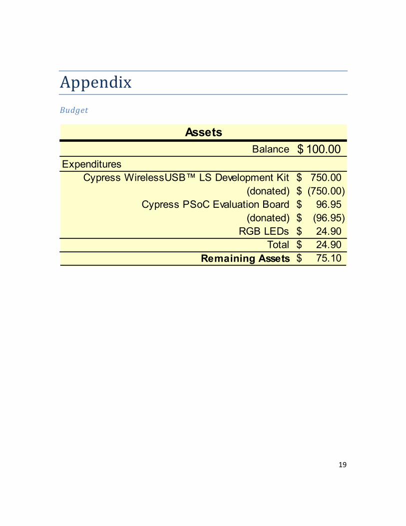
Budget
Balance 100.00$ Expenditures
Cypress WirelessUSB™ LS Development Kit 750.00$
(donated) (750.00)$
Cypress PSoC Evaluation Board 96.95$
(donated) (96.95)$
RGB LEDs 24.90$
Total 24.90$
Remaining Assets 75.10$
Assets