Embed Size (px)
Citation preview
RGB-D Mapping: Using Depth Cameras forDense 3D Modeling of Indoor Environments
Peter Henry1, Michael Krainin1, Evan Herbst1, Xiaofeng Ren2, Dieter Fox1,2
Abstract RGB-D cameras are novel sensing systems that capture RGB imagesalong with per-pixel depth information. In this paper we investigate how such cam-eras can be used in the context of robotics, specifically for building dense 3D mapsof indoor environments. Such maps have applications in robot navigation, manip-ulation, semantic mapping, and telepresence. We present RGB-D Mapping, a full3D mapping system that utilizes a novel joint optimization algorithm combiningvisual features and shape-based alignment. Visual and depth information are alsocombined for view-based loop closure detection, followed by pose optimization toachieve globally consistent maps. We evaluate RGB-D Mapping on two large indoorenvironments, and show that it effectively combines the visual and shape informa-tion available from RGB-D cameras.
1 Introduction
Building rich 3D maps of environments is an important task for mobile robotics,with applications in navigation, manipulation, semantic mapping, and telepresence.Most 3D mapping systems contain three main components: first, the spatial align-ment of consecutive data frames; second, the detection of loop closures; third, theglobally consistent alignment of the complete data sequence. While 3D point cloudsare extremely well suited for frame-to-frame alignment and for dense 3D reconstruc-tion, they ignore valuable information contained in images. Color cameras, on theother hand, capture rich visual information and are becoming more and more thesensor of choice for loop closure detection [21, 16, 30]. However, it is extremelyhard to extract dense depth from camera data alone, especially in indoor environ-ments with very dark or sparsely textured areas.
1University of Washington, Department of Computer Science & Engineering, Seattle, WA2Intel Labs Seattle, Seattle, WA
1

2 Peter Henry, Michael Krainin, Evan Herbst, Xiaofeng Ren, Dieter Fox
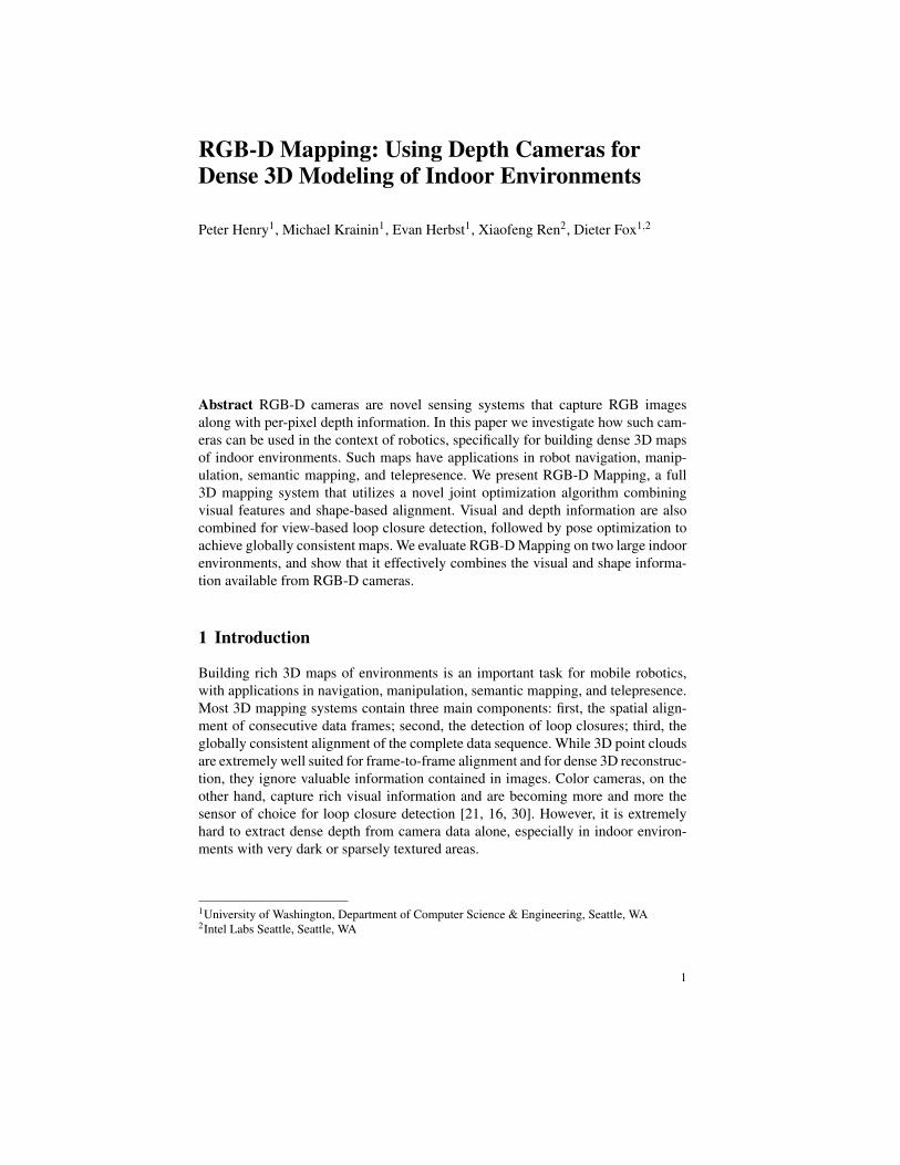
Fig. 1 (left) RGB image and (right) depth information captured by an RGB-D camera. Recentsystems can capture images at a resolution of up to 640x480 pixels at 30 frames per second. Whitepixels in the right image have no depth value, mostly due to occlusion, max distance, relativesurface angle, or surface material.
RGB-D cameras are sensing systems that capture RGB images along with per-pixel depth information. RGB-D cameras rely on either active stereo [15, 25] ortime-of-flight sensing [3, 12] to generate depth estimates at a large number of pix-els. While sensor systems with these capabilities have been custom-built for years,only now are they being packaged in form factors that make them attractive for re-search outside specialized computer vision groups. In fact, the key drivers for themost recent RGB-D camera systems are computer gaming and home entertainmentapplications [25].
RGB-D cameras allow the capture of reasonably accurate mid-resolution depthand appearance information at high data rates. In our work we use a camera de-veloped by PrimeSense [25], which captures 640x480 registered image and depthpoints at 30 frames per second. This camera is equivalent to the visual sensors inthe recently available Microsoft Kinect [20]. Fig. 1 shows an example frame ob-served with this RGB-D camera. As can be seen, the sensor provides dense depthestimates. However, RGB-D cameras have some important drawbacks with respectto 3D mapping: they provide depth only up to a limited distance (typically less than5m), their depth estimates are very noisy and their field of view (∼ 60◦) is far moreconstrained than that of the specialized cameras and laser scanners commonly usedfor 3D mapping (∼ 180◦).
In this paper we introduce RGB-D Mapping, a framework for using RGB-Dcameras to generate dense 3D models of indoor environments. RGB-D Mappingexploits the integration of shape and appearance information provided by these sys-tems. Alignment between frames is computed by jointly optimizing over both ap-pearance and shape matching. Our approach detects loop closures by matching dataframes against a subset of previously collected frames. To generate globally consis-tent alignments we use TORO, an optimization tool developed for SLAM [9]. Theoverall system can accurately align and map large indoor environments in near-realtime and is capable of handling situations such as featureless corridors and com-pletely dark rooms.
RGB-D Mapping 3
RGB-D Mapping maintains and updates a global model using small planar col-ored surface patches called surfels [23]. This representation enables the approach toefficiently reason about occlusions, to estimate the appropriate color extracted foreach part of the environment, and to provide good visualizations of the resultingmodel. Furthermore, surfels automatically adapt the resolution of the representationto the resolution of data available for each patch.
After discussing related work, we introduce RGB-D Mapping in Section 3. Ex-periments are presented in Section 4, followed by a discussion.
2 Related Work
The robotics and computer vision communities have developed many techniques for3D mapping using range scans [31, 32, 19, 21], stereo cameras [1, 16], monocularcameras [5], and even unsorted collections of photos [30, 7]. Most mapping sys-tems require the spatial alignment of consecutive data frames, the detection of loopclosures, and the globally consistent alignment of all data frames.
The solution to the frame alignment problem strongly depends on the data be-ing used. For 3D laser data, the iterated closest point (ICP) algorithm and variantsthereof are popular techniques [2, 31, 19, 27]. The ICP algorithm iterates betweenassociating each point in one time frame to the closest point in the other frame andcomputing the rigid transformation that minimizes distance between the point pairs.The robustness of ICP in 3D has been improved by, e.g., incorporating point-to-plane associations or point reflectance values [4, 28, 19].
Passive stereo systems can extract depth information for only a subset of featurepoints in each stereo pair. These feature points can then be aligned over consec-utive frames using an optimization similar to a single iteration of ICP, with theadditional advantage that appearance information can be used to solve the data as-sociation problem more robustly, typically via RANSAC [16, 1]. Monocular SLAMand mapping based on unsorted image sets are similar to stereo SLAM in that sparsefeatures are extracted from images to solve the correspondence problem. Projectivegeometry is used to define the spatial relationship between features [22, 5, 30], amuch harder problem to solve than correspondence in ICP.
For the loop closure problem, most recent approaches to 3D mapping rely on fastimage matching techniques [30, 5, 16, 21]. Once a loop closure is detected, the newcorrespondence between data frames can be used as an additional constraint in thegraph describing the spatial relationship between frames. Optimization of this posegraph results in a globally aligned set of frames [9].
While RGB-D Mapping follows the overall structure of recent 3D mapping tech-niques, it differs from existing approaches in the way it performs frame-to-framematching. While pure laser-based ICP is extremely robust for the 3D point cloudscollected by 3D laser scanning systems such as panning SICK scanners or 3D Velo-dyne scanners [21, 28], RGB-D cameras provide depth and color information for asmall field of view (60◦ in contrast to 180◦) and with less depth precision (≈3cm at
4 Peter Henry, Michael Krainin, Evan Herbst, Xiaofeng Ren, Dieter Fox
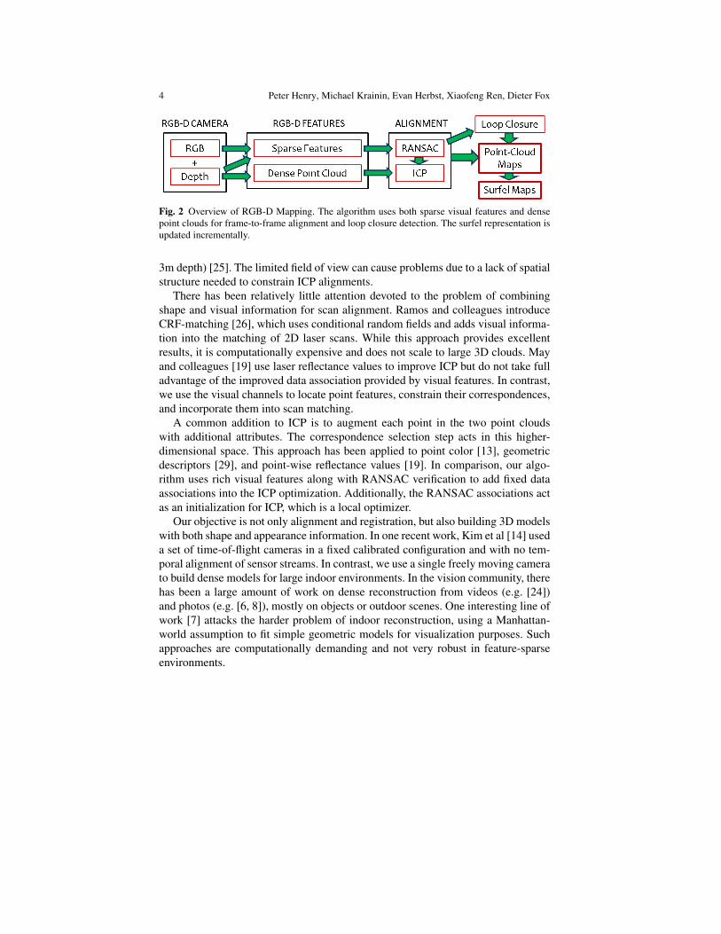
Fig. 2 Overview of RGB-D Mapping. The algorithm uses both sparse visual features and densepoint clouds for frame-to-frame alignment and loop closure detection. The surfel representation isupdated incrementally.
3m depth) [25]. The limited field of view can cause problems due to a lack of spatialstructure needed to constrain ICP alignments.
There has been relatively little attention devoted to the problem of combiningshape and visual information for scan alignment. Ramos and colleagues introduceCRF-matching [26], which uses conditional random fields and adds visual informa-tion into the matching of 2D laser scans. While this approach provides excellentresults, it is computationally expensive and does not scale to large 3D clouds. Mayand colleagues [19] use laser reflectance values to improve ICP but do not take fulladvantage of the improved data association provided by visual features. In contrast,we use the visual channels to locate point features, constrain their correspondences,and incorporate them into scan matching.
A common addition to ICP is to augment each point in the two point cloudswith additional attributes. The correspondence selection step acts in this higher-dimensional space. This approach has been applied to point color [13], geometricdescriptors [29], and point-wise reflectance values [19]. In comparison, our algo-rithm uses rich visual features along with RANSAC verification to add fixed dataassociations into the ICP optimization. Additionally, the RANSAC associations actas an initialization for ICP, which is a local optimizer.
Our objective is not only alignment and registration, but also building 3D modelswith both shape and appearance information. In one recent work, Kim et al [14] useda set of time-of-flight cameras in a fixed calibrated configuration and with no tem-poral alignment of sensor streams. In contrast, we use a single freely moving camerato build dense models for large indoor environments. In the vision community, therehas been a large amount of work on dense reconstruction from videos (e.g. [24])and photos (e.g. [6, 8]), mostly on objects or outdoor scenes. One interesting line ofwork [7] attacks the harder problem of indoor reconstruction, using a Manhattan-world assumption to fit simple geometric models for visualization purposes. Suchapproaches are computationally demanding and not very robust in feature-sparseenvironments.

RGB-D Mapping 5
Fig. 3 Example frame for RGB-D frame alignment. Left, the locations of SIFT features in theimage. Right, the same SIFT features shown in their position in the point cloud.
3 RGB-D Mapping
This section describes the different components of RGB-D Mapping. A flow chartof the overall system is shown in Fig. 2.
To align the current frame to the previous frame, the alignment step uses RGBD-ICP, our enhanced ICP algorithm that takes advantage of the combination of RGBand depth information. After this alignment step, the new frame is added to the dense3D model. This step also updates the surfels used for visualization and occlusionreasoning. A parallel loop closure detection thread uses the sparse feature pointsto match the current frame against previous observations, taking spatial constraintsinto account. If a loop closure is detected, a constraint is added to the pose graphand a global alignment process is triggered.
3.1 RGBD-ICP
In the Iterative Closest Point (ICP) algorithm [2], points in a source cloud Ps arematched with their nearest neighboring points in a target cloud Pt and a rigid trans-formation is found by minimizing the n-D error between associated points. Thistransformation may change the nearest neighbors for points in Ps, so the two steps ofassociation and optimization are alternated until convergence. ICP has been shownto be effective when the two clouds are already nearly aligned. Otherwise, the un-known data association between Ps and Pt can lead to convergence at an incorrectlocal minimum.
Alignment of images, by contrast, is typically done using sparse feature-pointmatching. A key advantage of visual features is that they can provide alignmentswithout requiring initialization. One widely used feature detector and descriptor isthe Scale Invariant Feature Transform (SIFT)[18]. Though feature descriptors arevery distinctive, they must be matched heuristically and there can be false matchesselected. The RANSAC algorithm is often used to determine a subset of feature pairs
6 Peter Henry, Michael Krainin, Evan Herbst, Xiaofeng Ren, Dieter Fox
RGBD-ICP (Ps,Pt ):
1: F = Extract RGB point features(Ps)
2: Ftarget = Extract RGB point features(Pt )
3: (t∗,A f ) = Perform RANSAC Alignment( F,Ftarget)
4: repeat5: Ad = Compute Closest Points( t∗,Ps,Pt )
6: t∗ = argmint α
(1|A f | ∑i∈A f
wi∣∣t( f i
s)− f it∣∣2)+(1−α)
(1|Ad | ∑ j∈Ad
w j
∣∣∣(t(p js)− p j
t ) ·njt
∣∣∣2)7: until (Error Change(t∗)≤ θ ) or (maxIter reached)
8: return t∗
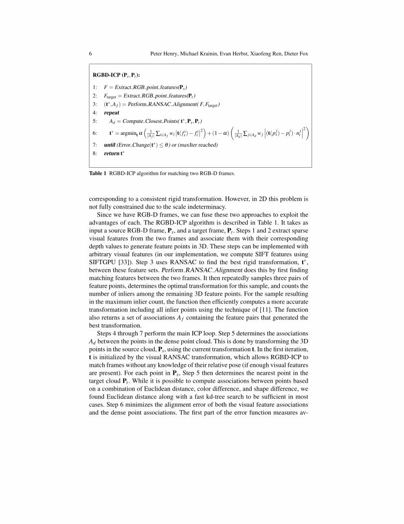
Table 1 RGBD-ICP algorithm for matching two RGB-D frames.
corresponding to a consistent rigid transformation. However, in 2D this problem isnot fully constrained due to the scale indeterminacy.
Since we have RGB-D frames, we can fuse these two approaches to exploit theadvantages of each. The RGBD-ICP algorithm is described in Table 1. It takes asinput a source RGB-D frame, Ps, and a target frame, Pt . Steps 1 and 2 extract sparsevisual features from the two frames and associate them with their correspondingdepth values to generate feature points in 3D. These steps can be implemented witharbitrary visual features (in our implementation, we compute SIFT features usingSIFTGPU [33]). Step 3 uses RANSAC to find the best rigid transformation, t∗,between these feature sets. Perform RANSAC Alignment does this by first findingmatching features between the two frames. It then repeatedly samples three pairs offeature points, determines the optimal transformation for this sample, and counts thenumber of inliers among the remaining 3D feature points. For the sample resultingin the maximum inlier count, the function then efficiently computes a more accuratetransformation including all inlier points using the technique of [11]. The functionalso returns a set of associations A f containing the feature pairs that generated thebest transformation.
Steps 4 through 7 perform the main ICP loop. Step 5 determines the associationsAd between the points in the dense point cloud. This is done by transforming the 3Dpoints in the source cloud, Ps, using the current transformation t. In the first iteration,t is initialized by the visual RANSAC transformation, which allows RGBD-ICP tomatch frames without any knowledge of their relative pose (if enough visual featuresare present). For each point in Ps, Step 5 then determines the nearest point in thetarget cloud Pt . While it is possible to compute associations between points basedon a combination of Euclidean distance, color difference, and shape difference, wefound Euclidean distance along with a fast kd-tree search to be sufficient in mostcases. Step 6 minimizes the alignment error of both the visual feature associationsand the dense point associations. The first part of the error function measures av-
RGB-D Mapping 7
erage distances for the visually associated feature points, and the second part com-putes a similar error term for the dense point associations. For the dense points weemploy a point-to-plane error term that minimizes the distance error along eachtarget point’s normal. These normals, {n j
t }, are computed efficiently by principalcomponent analysis over a small neighborhood of each target point. Point-to-planeICP has been shown to generate more accurate alignments than point-to-point ICPdue to an improved interpolation between points [28]. Finally, the two componentsare weighted using a factor α . Since the point-to-plane error metric has no knownclosed-form solution, and thus requires the use of a nonlinear optimizer, RGBD-ICPperforms the minimization using Levenberg-Marquardt.
The loop exits after the error no longer decreases significantly or a maximumnumber of iterations is reached. Otherwise, the dense data associations are recom-puted using the most recent transformation. Note that feature point data associationsare not recomputed after the RANSAC procedure. This avoids that the dense ICPcomponents might cause the point clouds to drift apart, which can happen in under-constrained cases such as large flat walls.
We find that downsampling the source and target clouds given to ICP by a factorof 4 to 10 gives the best compromise between matching speed and accuracy.
If RANSAC fails to find a large number of inliers, we initialize the ICP transfor-mation using a constant-velocity motion model: assume the motion between framesn and n+1 is similar to that between frames n−1 and n.
3.2 Loop Closure Detection and Global Optimization
Alignment between successive frames is a good method for tracking the camera po-sition over moderate distances. However, errors in alignment between a particularpair of frames, and noise and quantization in depth values, cause the estimation ofcamera position to drift over time, leading to inaccuracies in the map. This is mostnoticeable when the camera follows a long path, eventually returning to a locationpreviously visited. The cumulative error in frame alignment results in a map thathas two representations of the same region in different locations. This is known asthe loop closure problem, and our solution to it has two parts. First, loop closure de-tection is needed to recognize when the camera has returned to a previously visitedlocation. Second, the map must be corrected to merge duplicate regions. Our over-all strategy is to represent constraints between frames with a graph structure, withedges between frames corresponding to geometric constraints. The relative trans-formations from the alignment of sequential frames give us some constraints, sowithout any loop closure, the graph consists of a linear chain. Loop closures arerepresented as constraints between frames that are not temporally adjacent.
To keep the graph relatively sparse we define keyframes, which are a subset of thealigned frames. We determine keyframes based on visual overlap, adapting the den-sity of keyframes to camera motion and local appearance. After we align a frameF , we reuse the SIFT features to find a rigid transformation with the most recentkeyframe, using the same RANSAC procedure defined for frame-to-frame align-
8 Peter Henry, Michael Krainin, Evan Herbst, Xiaofeng Ren, Dieter Fox
ment. As long as the number of RANSAC inliers is above a threshold, we do notneed to add F as a keyframe. As the camera continues to move, its view containsprogressively fewer 3D feature point matches with the previous keyframe. The firstframe that fails to match against the previous keyframe becomes the next keyframe.Because we never remove pose-graph edges, contiguous keyframes are always con-strained in the graph.
Each time we create a new keyframe we attempt to detect a loop closure witheach previous keyframe. A closure is detected if enough geometrically consistent3D feature point matches are recovered by RANSAC, and if so, we add an edge tothe graph representing this newly discovered constraint. For this stage we modifyRGBD-ICP slightly to return FAIL if no RANSAC match is found with sufficientinliers, so that the same algorithm that performs frame-to-frame matching also per-forms loop closure detection and initializes pose-graph edges. We only perform theRANSAC check with keyframes that are within a small distance of our current po-sition estimate.
In order to minimize the conflict between sequential constraints and loop clo-sure constraints we employ TORO [9, 10], a system for efficiently minimizing theerror in such graphs where vertices are parameterized by translation and rotationcomponents and edges represent constraints between the parameters with associ-ated covariance matrices. TORO uses stochastic gradient descent to maximize thelikelihood of the vertex parameters subject to the constraints. We run TORO to con-vergence each time loop closure is detected, initializing it with the output of theprevious TORO run and the contiguous-frame constraints added since then.
3.3 Surfel Representation
Considering that each frame from the RGB-D camera gives us roughly 250,000points, it is necessary to create a more concise representation of the map. One optionis to downsample the clouds. However, it is more appealing to incorporate all theinformation from each frame into a concise representation for visualization. Onemethod for doing this is surfels [23, 17]. A surfel consists of a location, a surfaceorientation, a patch size and a color. As more point clouds are added to the surfelrepresentation, we follow rules similar to those of [23] and [17] for updating, adding,and removing surfels. Surfels store a measure of confidence, which is increasedthrough being seen from multiple angles over time. Surfels with low confidence areremoved from the representation. Because surfels have a notion of size (obtainedinitially from the depth of the original point in the RGB-D frame), we can reasonabout occlusion, so if an existing surfel is seen through too often, it can be removed.
Based on the estimated normals within each RGB-D frame, the surfel normaldirections can be updated as well. We can also wait to add surfels until their normalis pointed (within some angle) towards the camera position, which leads to a moreaccurate recovery of the surfel size. The color of a surfel is determined from theRGB-D frame most aligned with the normal direction.
RGB-D Mapping 9
4 Experiments
We performed several experiments to evaluate different aspects of RGB-D Mapping.Specifically, we demonstrate the ability of our system to build consistent maps oflarge scale indoor environments, we show that our joint ICP algorithm improvesaccuracy of frame to frame alignment, and we illustrate the advantageous propertiesof the surfel representation.
4.1 Large-Scale Environments
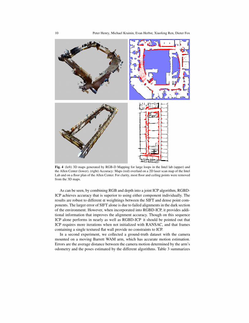
We tested RGB-D Mapping in two indoor environments: the Intel Labs Seattle of-fices and the University of Washington computer science building. During mapping,the camera was carried by a person, and generally pointed in the direction of travel.The left panels in Fig. 4 show 3D maps built for large loops in these environments.The loops in the upper and lower panel are 71 and 114 meters long, respectively.To assess the consistency of these maps we overlaid our 3D maps onto 2D layoutsgenerated by different means. The right panels in Fig. 4 show overlays of our mapsonto an Intel lab map built with a SICK laser scanner using a standard SLAM ap-proach and an architectural floor plan of the Allen Center. For clarity, most floor andceiling points were removed from our 3D maps; the remaining 3D points are shownin red. RGB-D Mapping produces very consistent maps.
4.2 Benefits of RGBD-ICP
To more thoroughly evaluate the benefits of RGBD-ICP, we determined ground-truth poses in the Intel lab loop and also used a Barrett WAM manipulator to provideground-truth poses in a small-scale experiment.
In the first experiment, we placed 16 markers around the Intel loop and measuredthe true distance between consecutive markers. A challenging dataset was then col-lected at night with the lights turned off in a hallway section of the building. Thecamera was carried sequentially between the marker locations and placed carefullyon a tripod at each marker location, returning finally to the starting marker. In thisway we obtained 16 measurements of sequential frame alignment error over smallsections of the map by measuring the difference between real-world distance andbetween-marker distance determined by successive frame-to-frame alignments. Ta-ble 2 summarizes the results for different α values, which weigh the RGB and densepoint contributions in RGBD-ICP, resulting in pure SIFT alignment or ICP in theextreme cases.
α weight 0.0 (ICP) 0.2 0.5 0.8 1.0 (SIFT)Mean error [m] 0.22 0.19 0.16 0.18 1.29
Table 2 Sequential alignment comparison on large scale marker sequence.
10 Peter Henry, Michael Krainin, Evan Herbst, Xiaofeng Ren, Dieter Fox
Fig. 4 (left) 3D maps generated by RGB-D Mapping for large loops in the Intel lab (upper) andthe Allen Center (lower). (right) Accuracy: Maps (red) overlaid on a 2D laser scan map of the IntelLab and on a floor plan of the Allen Center. For clarity, most floor and ceiling points were removedfrom the 3D maps.
As can be seen, by combining RGB and depth into a joint ICP algorithm, RGBD-ICP achieves accuracy that is superior to using either component individually. Theresults are robust to different α weightings between the SIFT and dense point com-ponents. The larger error of SIFT alone is due to failed alignments in the dark sectionof the environment. However, when incorporated into RGBD-ICP, it provides addi-tional information that improves the alignment accuracy. Though on this sequenceICP alone performs in nearly as well as RGBD-ICP it should be pointed out thatICP requires more iterations when not initialized with RANSAC, and that framescontaining a single textured flat wall provide no constraints to ICP.
In a second experiment, we collected a ground-truth dataset with the cameramounted on a moving Barrett WAM arm, which has accurate motion estimation.Errors are the average distance between the camera motion determined by the arm’sodometry and the poses estimated by the different algorithms. Table 3 summarizes
RGB-D Mapping 11
Method Avg. Translational Avg. AngularError (m) Error (deg)
SIFT .168 4.5ICP .144 3.9RGBD-ICP (α = 0.5) .123 3.3RGBD-ICP + TORO .069 2.8
Table 3 Sequential alignment comparison on WAM-arm sequence.
(a) (b)
(c) (d)
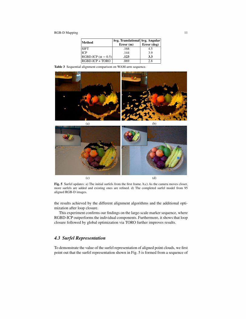
Fig. 5 Surfel updates: a) The initial surfels from the first frame. b,c) As the camera moves closer,more surfels are added and existing ones are refined. d) The completed surfel model from 95aligned RGB-D images.
the results achieved by the different alignment algorithms and the additional opti-mization after loop closure.
This experiment confirms our findings on the large-scale marker sequence, whereRGBD-ICP outperforms the individual components. Furthermore, it shows that loopclosure followed by global optimization via TORO further improves results.
4.3 Surfel Representation
To demonstrate the value of the surfel representation of aligned point clouds, we firstpoint out that the surfel representation shown in Fig. 5 is formed from a sequence of
12 Peter Henry, Michael Krainin, Evan Herbst, Xiaofeng Ren, Dieter Fox
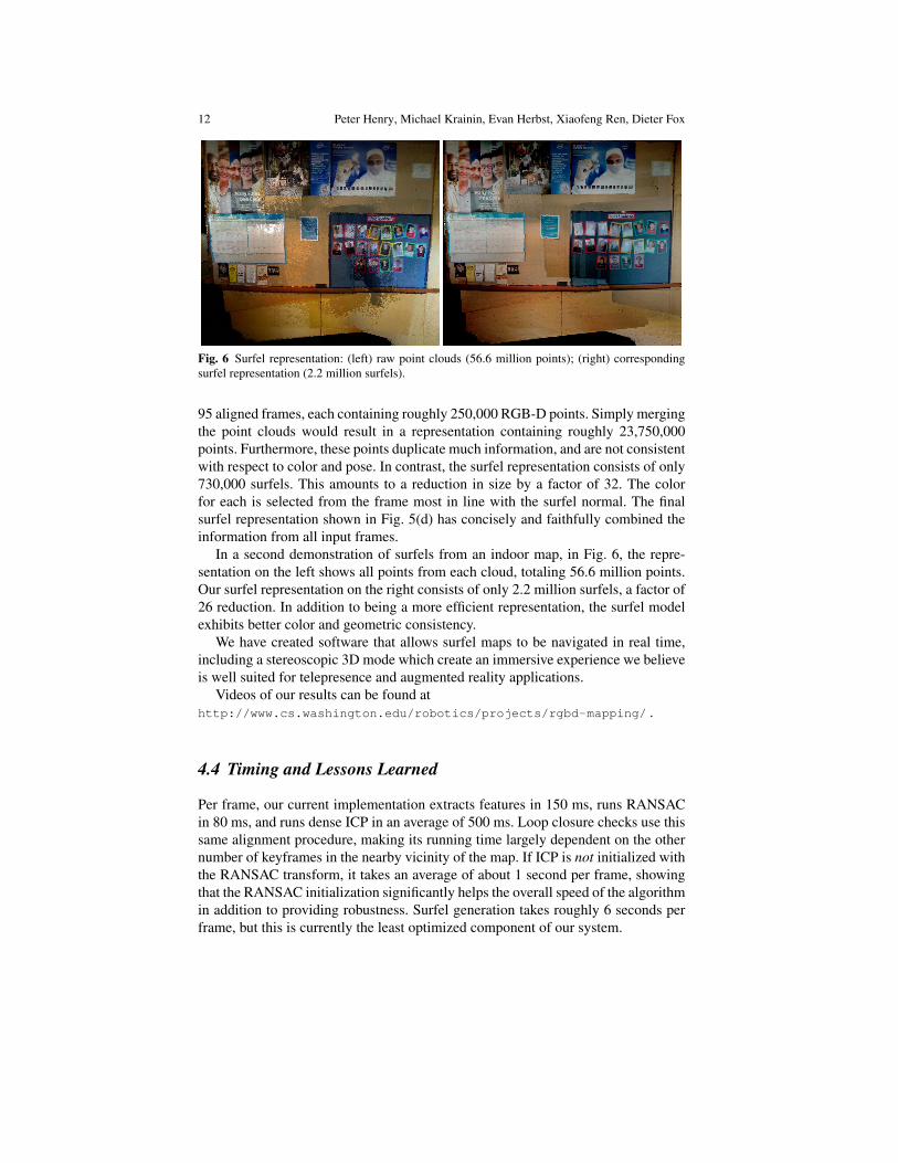
Fig. 6 Surfel representation: (left) raw point clouds (56.6 million points); (right) correspondingsurfel representation (2.2 million surfels).
95 aligned frames, each containing roughly 250,000 RGB-D points. Simply mergingthe point clouds would result in a representation containing roughly 23,750,000points. Furthermore, these points duplicate much information, and are not consistentwith respect to color and pose. In contrast, the surfel representation consists of only730,000 surfels. This amounts to a reduction in size by a factor of 32. The colorfor each is selected from the frame most in line with the surfel normal. The finalsurfel representation shown in Fig. 5(d) has concisely and faithfully combined theinformation from all input frames.
In a second demonstration of surfels from an indoor map, in Fig. 6, the repre-sentation on the left shows all points from each cloud, totaling 56.6 million points.Our surfel representation on the right consists of only 2.2 million surfels, a factor of26 reduction. In addition to being a more efficient representation, the surfel modelexhibits better color and geometric consistency.
We have created software that allows surfel maps to be navigated in real time,including a stereoscopic 3D mode which create an immersive experience we believeis well suited for telepresence and augmented reality applications.
Videos of our results can be found athttp://www.cs.washington.edu/robotics/projects/rgbd-mapping/ .
4.4 Timing and Lessons Learned
Per frame, our current implementation extracts features in 150 ms, runs RANSACin 80 ms, and runs dense ICP in an average of 500 ms. Loop closure checks use thissame alignment procedure, making its running time largely dependent on the othernumber of keyframes in the nearby vicinity of the map. If ICP is not initialized withthe RANSAC transform, it takes an average of about 1 second per frame, showingthat the RANSAC initialization significantly helps the overall speed of the algorithmin addition to providing robustness. Surfel generation takes roughly 6 seconds perframe, but this is currently the least optimized component of our system.
RGB-D Mapping 13
RANSAC is the faster and more reliable alignment component when consideredindividually. However, there are situations where it fails and the joint optimizationis required. For some frames, many detected visual features are out of range of thedepth sensor, so those features have no associated 3D points and do not participatein the RANSAC procedure. Also, when the majority of the features lie in a smallregion of the image, they do not provide very strong constraints on the motion. Forexample, in badly lit halls it is common to see features only on one side wall. It isin situations such as these that RGBD-ICP provides notably better alignment.
5 Conclusion
Building accurate, dense models of indoor environments has many applications inrobotics, telepresence, gaming, and augmented reality. Limited lighting, lack of dis-tinctive features, repetitive structures, and the demand for rich detail are inherentto indoor environments, and handling these issues has proved a challenging taskfor both robotics and computer vision communities. Laser scanning approaches aretypically expensive and slow and need additional registration to add appearance in-formation (visual details). Vision-only approaches to dense 3D reconstruction oftenrequire a prohibitive amount of computation, suffer from lack of robustness, andcannot yet provide dense, accurate 3D models.
We investigate how potentially inexpensive depth cameras developed mainly forgaming and entertainment applications can be used for building dense 3D maps ofindoor environments. The key insights of this investigation are, first, that existingframe matching techniques are not sufficient to provide robust visual odometry withthese cameras; second, that a tight integration of depth and color information canyield robust frame matching and loop closure detection; third, that building on bestpractices in SLAM and computer graphics makes it possible to build and visualizeaccurate and extremely rich 3D maps with such cameras; and, fourth, that it will befeasible to build complete robot navigation and interaction systems solely based oninexpensive depth cameras.
We introduce RGB-D Mapping, a framework that can generate dense 3D maps ofindoor environments despite the limited depth precision and field of view providedby RGB-D cameras. At the core of this framework is RGBD-ICP, a novel ICP variantthat takes advantage of the richness of information contained in RGB-D data. RGB-D Mapping also incorporates a surfel representation to enable occlusion reasoningand visualization.
Given that RGB-D cameras will soon be available to the public at a low price (webelieve less than 100 dollars), an RGB-D-based modeling system will potentiallyhave a huge impact on everyday life, allowing people to build 3D models of arbi-trary indoor environments. Furthermore, our results indicate that RGB-D camerascould be used to build robust robotic mapping, navigation, and interaction systems.Along with the potential decrease in cost of the resulting navigation platform, theapplication of RGB-D cameras might be an important step to enable the develop-ment of useful, affordable robot platforms.
14 Peter Henry, Michael Krainin, Evan Herbst, Xiaofeng Ren, Dieter Fox
Despite these encouraging results, our system has several shortcomings that de-serve future effort. Our current implementation of RGB-D Mapping is not real-time,but we believe that an efficient implementation taking advantage of modern GPUhardware can certainly achieve the speedup needed to operate online. The globalalignment process of RGB-D Mapping is still limited. Instead of optimizing overcamera poses only, a joint optimization over camera poses and 3D points couldresult in even more consistent reconstructions. The computer graphics communityhas developed extremely sophisticated visualization techniques, and incorporatingthese into RGB-D mapping could improve the visual quality of the 3D maps. An-other interesting avenue for research is the extraction of object representations fromthe rich information contained in dense 3D maps. Other areas for future researchinclude the development of exploration techniques for building complete 3D mapsand the extension to dynamic environments.
We would like to thank Louis LeGrand and Brian Mayton for their support withthe PrimeSense camera, and Marvin Cheng for his work on visualization. This workwas funded in part by an Intel grant, by ONR MURI grants number N00014-07-1-0749 and N00014-09-1-1052, and by the NSF under contract number IIS-0812671.Part of this work was also conducted through collaborative participation in theRobotics Consortium sponsored by the U.S Army Research Laboratory under theCollaborative Technology Alliance Program, Cooperative Agreement W911NF-10-2-0016.
References
1. A. Akbarzadeh, J. M. Frahm, P. Mordohai, B. Clipp, C. Engels, D. Gallup, P. Merrell,M. Phelps, S. Sinha, B. Talton, L. Wang, Q. Yang, H. Stewenius, R. Yang, G. Welch,H. Towles, D. Nister, and M. Pollefeys. Towards urban 3D reconstruction from video. InProc. of the Third International Symposium on 3D Data Processing, Visualization and Trans-mission (3DPVT), 2006.
2. P. J. Besl and N. D. McKay. A method for registration of 3-d shapes. IEEE Transactions onPattern Analysis and Machine Intelligence (PAMI), 14(2), 1992.
3. Canesta. http://www.canesta.com/.4. Yang Chen and Gerard Medioni. Object modeling by registration of multiple range images.
Image Vision Comput., 10(3):145–155, 1992.5. L. Clemente, A. Davison, I. Reid, J. Neira, and J. Tardos. Mapping large loops with a single
hand-held camera. In Proc. of Robotics: Science and Systems (RSS), 2007.6. P. Debevec, C. J. Taylor, and Jitendra Malik. Modeling and rendering architecture from pho-
tographs: A hybrid geometryand image-based approach. In SIGGRAPH, 1996.7. Y. Furukawa, B. Curless, S. Seitz, and R. Szeliski. Reconstructing building interiors from
images. In Proc. of the International Conference on Computer Vision (ICCV), 2009.8. Y. Furukawa and J. Ponce. Patch-based multi-view stereo software (PMVS): http://
grail.cs.washington.edu/software/pmvs/.9. G. Grisetti, S. Grzonka, C. Stachniss, P. Pfaff, and W. Burgard. Estimation of accurate maxi-
mum likelihood maps in 3D. In Proc. of the IEEE/RSJ International Conference on IntelligentRobots and Systems (IROS), 2007.

RGB-D Mapping 15
10. G. Grisetti, C. Stachniss, S. Grzonka, and W. Burgard. A tree parameterization for efficientlycomputing maximum likelihood maps using gradient descent. In Proc. of Robotics: Scienceand Systems (RSS), 2007.
11. B. K. P. Horn. Closed-form solution of absolute orientation using unit quaternions. J. Opt.Soc. Am. A, 4(4):629–642, 1987.
12. Mesa Imaging. http://www.mesa-imaging.ch/.13. A. Johnson and S. B. Kang. Registration and integration of textured 3-d data. In International
Conference on Recent Advances in 3-D Digital Imaging and Modeling (3DIM ’97), pages 234– 241, May 1997.
14. Y. M. Kim, C. Theobalt, J. Diebel, J. Kosecka, B. Micusik, and S. Thrun. Multi-view imageand ToF sensor fusion for dense 3D reconstruction. In Workshop on 3-D Digital Imaging andModeling (3DIM), 2009.
15. K. Konolige. Projected texture stereo. In Proc. of the IEEE International Conference onRobotics & Automation (ICRA), 2010.
16. K. Konolige and M. Agrawal. FrameSLAM: From bundle adjustment to real-time visualmapping. IEEE Transactions on Robotics, 25(5), 2008.
17. M. Krainin, P. Henry, X. Ren, and D. Fox. Manipulator and object tracking for in hand 3Dobject modeling. Technical Report UW-CSE-10-09-01, University of Washington, 2010.http://www.cs.washington.edu/ai/Mobile_Robotics/projects/hand_tracking/.
18. D. Lowe. Discriminative image features from scale-invariant keypoints. International Journalof Computer Vision, 60(2), 2004.
19. S. May, D. Droschel, D. Holz, E. Fuchs, S. Malis, A. Nuchter, and J. Hertzberg. Three-dimensional mapping with time-of-flight cameras. Journal of Field Robotics (JFR), 26(11-12), 2009.
20. Microsoft. http://www.xbox.com/en-US/kinect, 2010.21. P. Newman, G. Sibley, M. Smith, M. Cummins, A. Harrison, C. Mei, I. Posner, R. Shade,
D. Schroter, L. Murphy, W. Churchill, D. Cole, and I. Reid. Navigating, recognising anddescribing urban spaces with vision and laser. International Journal of Robotics Research(IJRR), 28(11-12), 2009.
22. D. Nister. An efficient solution to the five-point relative pose problem. IEEE Transactions onPattern Analysis and Machine Intelligence (PAMI), 26(6):756–77, 2004.
23. H. Pfister, M. Zwicker, J. van Baar, and M. Gross. Surfels: Surface elements as renderingprimitives. In ACM Transactions on Graphics (Proc. of SIGGRAPH), 2000.
24. M. Pollefeys, D. Nister, J.-M. Frahm, A. Akbarzadeh, P. Mordohai, B. Clipp, C. Engels,D. Gallup, S.-J. Kim, P. Merrell, C. Salmi, S. Sinha, B. Talton, L. Wang, Q. Yang, H. Stewe-nius, R. Yang, G. Welch, and H. Towles. Detailed real-time urban 3D reconstruction fromvideo. International Journal of Computer Vision, 72(2):143–67, 2008.
25. PrimeSense. http://www.primesense.com/.26. F. Ramos, D. Fox, and H. Durrant-Whyte. CRF-matching: Conditional random fields for
feature-based scan matching. In Proc. of Robotics: Science and Systems (RSS), 2007.27. S. Rusinkiewicz and M. Levoy. Efficient variants of the ICP algorithm. In Third International
Conference on 3D Digital Imaging and Modeling, 2001.28. A. Segal, D. Haehnel, and S. Thrun. Generalized-ICP. In Proc. of Robotics: Science and
Systems (RSS), 2009.29. G. C. Sharp, S. W. Lee, and D. K. Wehe. ICP registration using invariant features. IEEE
Transactions on Pattern Analysis and Machine Intelligence (PAMI), 24(1):90–102, 2002.30. N. Snavely, S. Seitz, and R. Szeliski. Photo tourism: Exploring photo collections in 3D. In
ACM Transactions on Graphics (Proc. of SIGGRAPH), 2006.31. S. Thrun, W. Burgard, and D. Fox. A real-time algorithm for mobile robot mapping with
applications to multi-robot and 3D mapping. In Proc. of the IEEE International Conferenceon Robotics & Automation (ICRA), 2000.
32. R. Triebel and W. Burgard. Improving simultaneous mapping and localization in 3D usingglobal constraints. In Proc. of the National Conference on Artificial Intelligence (AAAI), 2005.
33. C. Wu. SiftGPU: A GPU implementation of scale invariant feature transform (SIFT). http://cs.unc.edu/˜ccwu/siftgpu, 2007.


![Self-Supervised Drivable Area and Road Anomaly ...RGB-D cameras, such as Kinect [1], are visual sensors that can stream RGB and depth images at the same time [2]–[4]. We use an RGB-D](https://img.pdfslide.us/doc/110x75/6011e91211febc35b76e0652/self-supervised-drivable-area-and-road-anomaly-rgb-d-cameras-such-as-kinect.jpg)