Embed Size (px)
Citation preview
RK_zhaw2007_v1.0 1
RFID: Schlüssel zum Internet der Dinge
Prof. Roland KuengContact: [email protected]
RK_zhaw2007_v1.0 2
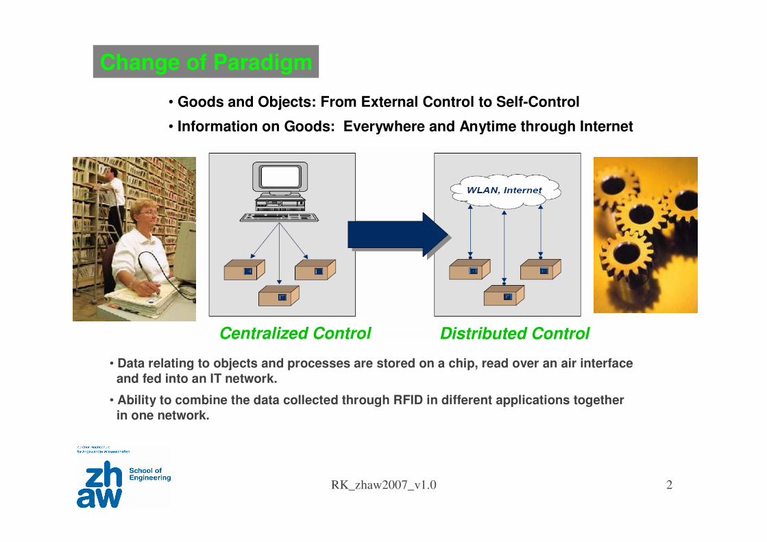
Centralized Control Distributed Control
Change of Paradigm
• Goods and Objects: From External Control to Self-Control
• Information on Goods: Everywhere and Anytime through Internet
• Data relating to objects and processes are stored on a chip, read over an air interface
and fed into an IT network.
• Ability to combine the data collected through RFID in different applications together
in one network.

RK_zhaw2007_v1.0 3
Market Vision
• Evolving connectivity at anytime, any place, anyone to seamless connectivity to anything.
•Radio Frequency IDentification is seen as one of the pivotal enabler of the Internet of Things.
RK_zhaw2007_v1.0 4
0 51234567890
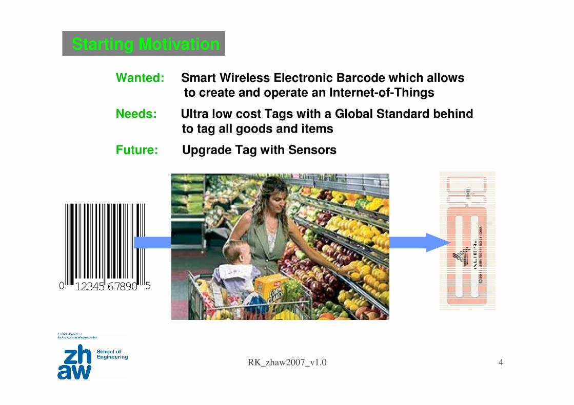
Wanted: Smart Wireless Electronic Barcode which allows to create and operate an Internet-of-Things
Needs: Ultra low cost Tags with a Global Standard behind
to tag all goods and items
Future: Upgrade Tag with Sensors
Starting Motivation
RK_zhaw2007_v1.0 5
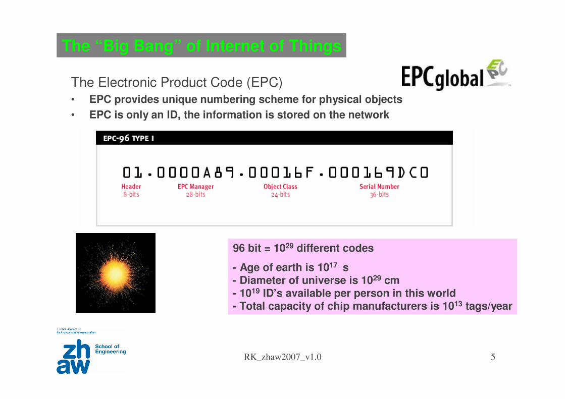
The “Big Bang” of Internet of Things
The Electronic Product Code (EPC)
• EPC provides unique numbering scheme for physical objects
• EPC is only an ID, the information is stored on the network
96 bit = 1029 different codes
- Age of earth is 1017 s- Diameter of universe is 1029 cm- 1019 ID’s available per person in this world- Total capacity of chip manufacturers is 1013 tags/year
RFID Basics
RK_zhaw2007_v1.0 7
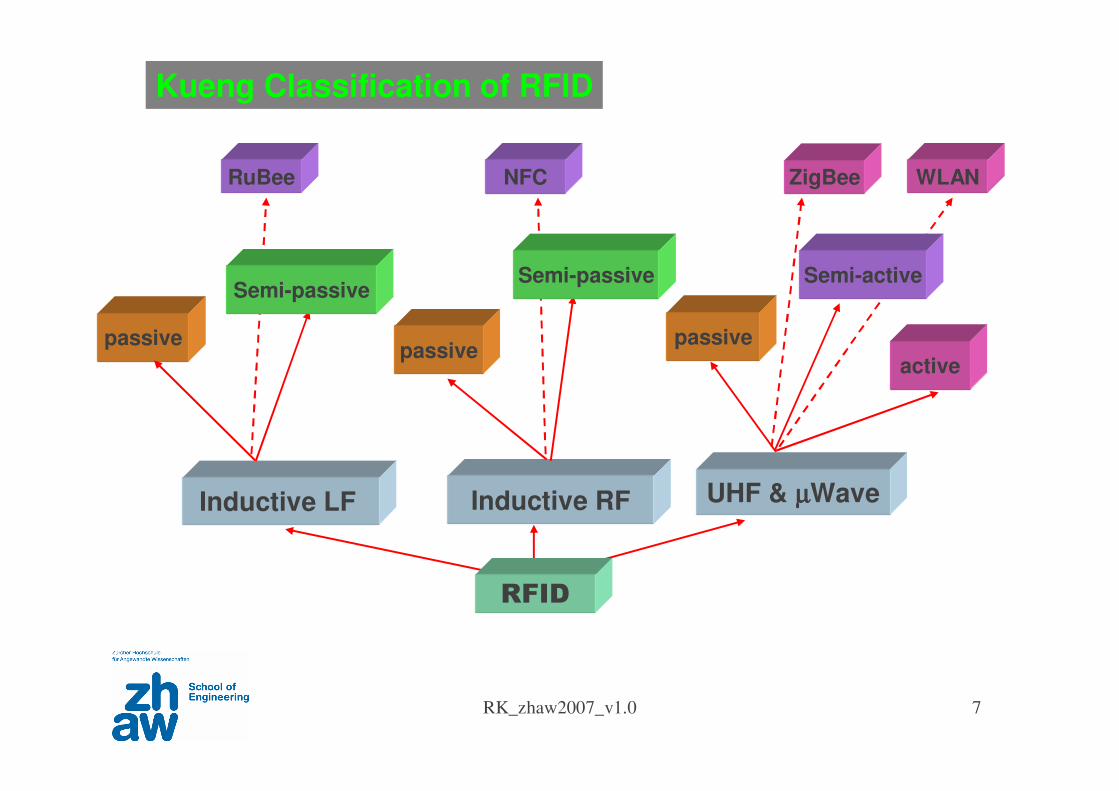
UHF & µµµµWaveInductive RFInductive LF
passivepassive
passive
active
Kueng Classification of RFID
RFID
ZigBeeRuBee NFC WLAN
Semi-passiveSemi-passive Semi-active
RK_zhaw2007_v1.0 8
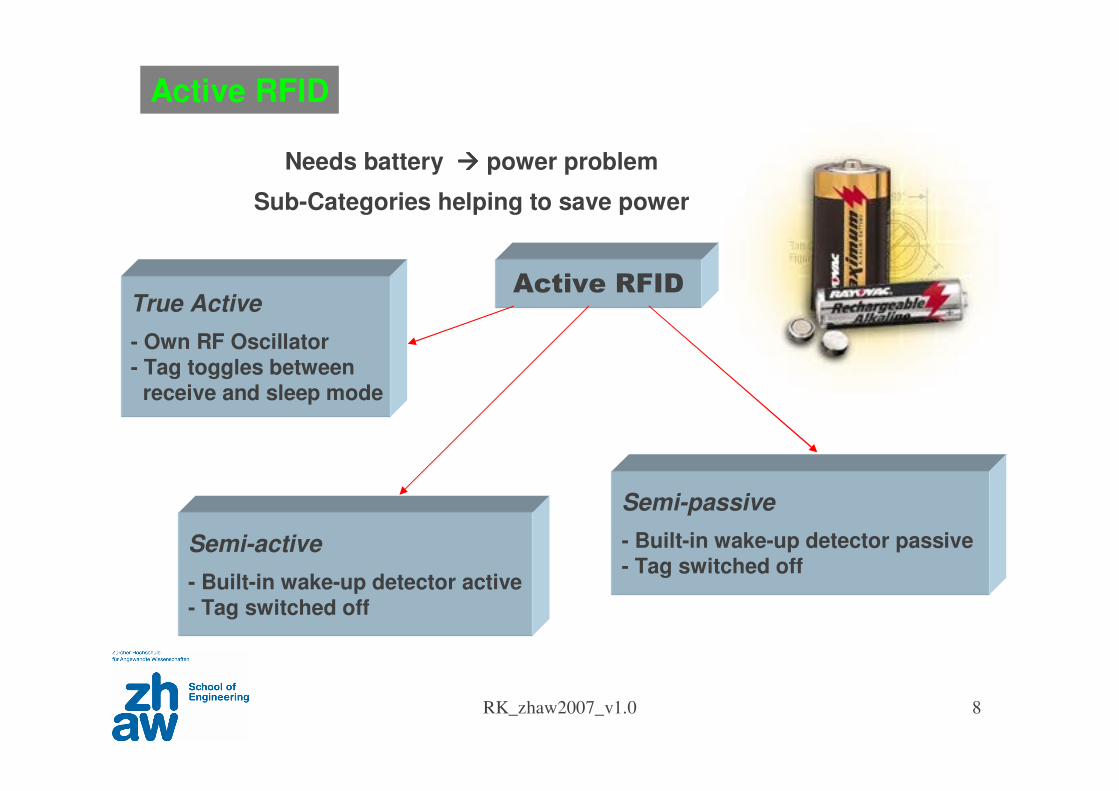
Needs battery power problem
Sub-Categories helping to save power
Active RFID
Active RFID
Semi-active
- Built-in wake-up detector active- Tag switched off
Semi-passive
- Built-in wake-up detector passive- Tag switched off
True Active
- Own RF Oscillator- Tag toggles between
receive and sleep mode
RK_zhaw2007_v1.0 9
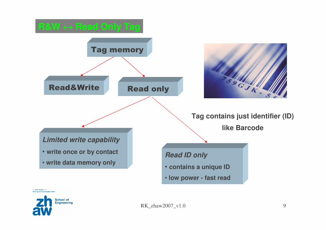
Tag contains just identifier (ID)
like Barcode
Read only
R&W ↔↔↔↔ Read Only Tag
Read ID only
• contains a unique ID
• low power - fast read
Limited write capability
• write once or by contact
• write data memory only
Tag memory
Read&Write
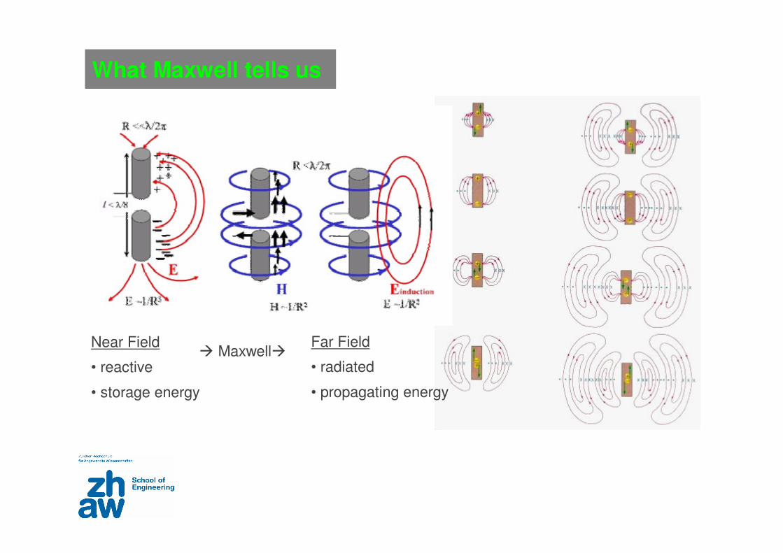
Near Field
• reactive
• storage energy
MaxwellFar Field
• radiated
• propagating energy
What Maxwell tells us
RK_zhaw2007_v1.0 11
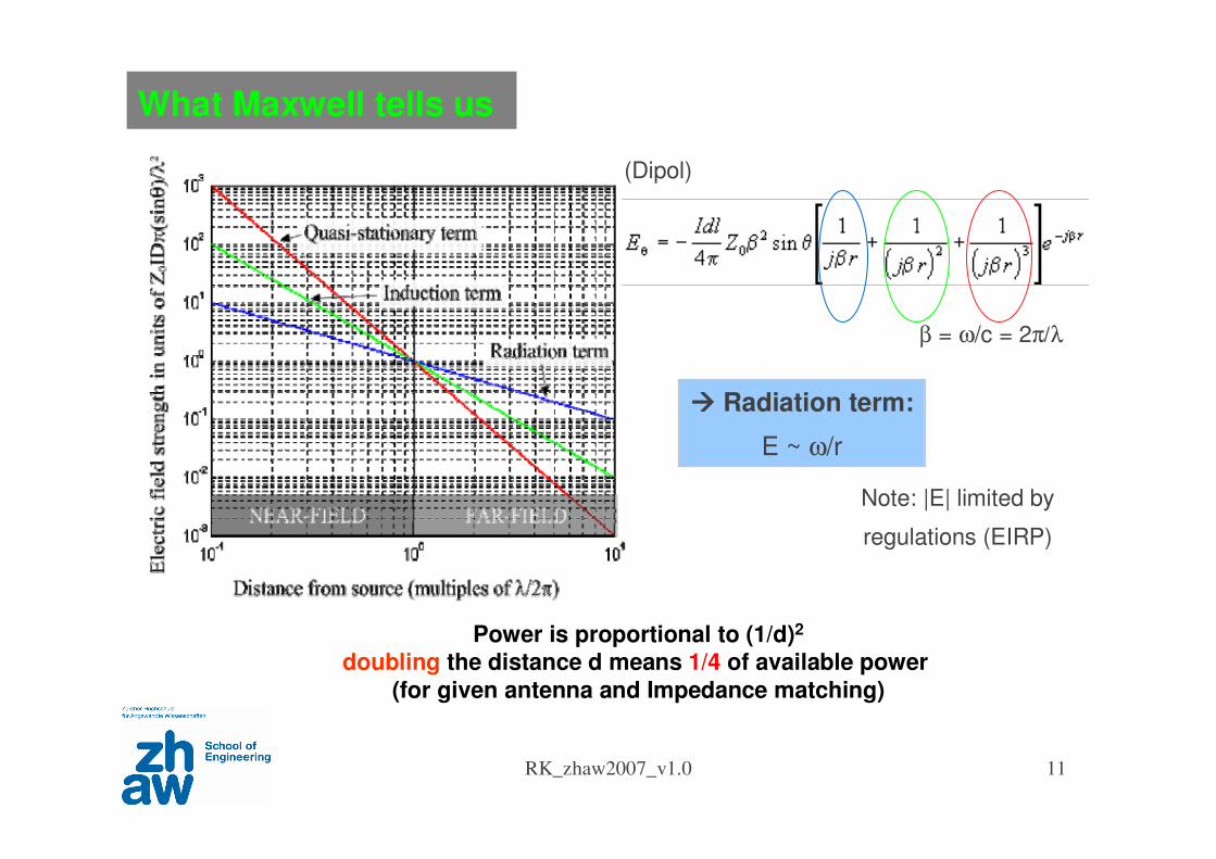
What Maxwell tells us
(Dipol)
β = ω/c = 2π/λ
Radiation term:
E ~ ω/r
Power is proportional to (1/d)2
doubling the distance d means 1/4 of available power
(for given antenna and Impedance matching)
Note: |E| limited by
regulations (EIRP)
RK_zhaw2007_v1.0 12
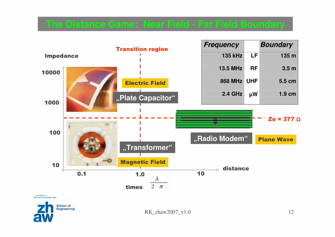
Frequency Boundary
135 kHz LF 135 m
13.5 MHz RF 3.5 m
868 MHz UHF 5.5 cm
2.4 GHz µµµµW 1.9 cm
The Distance Game: Near Field - Far Field Boundary
Plane Wave
Electric Field
Magnetic Field
Magnetic Field
(Inductive)
Electric Field
(Capacitive)
Transition region
0.1 1.0 10
Zo = 377 ΩΩΩΩ
10
100
1000
10000
times
Impedance
distance
„Radio Modem“
„Plate Capacitor“
„Transformer“
RK_zhaw2007_v1.0 13
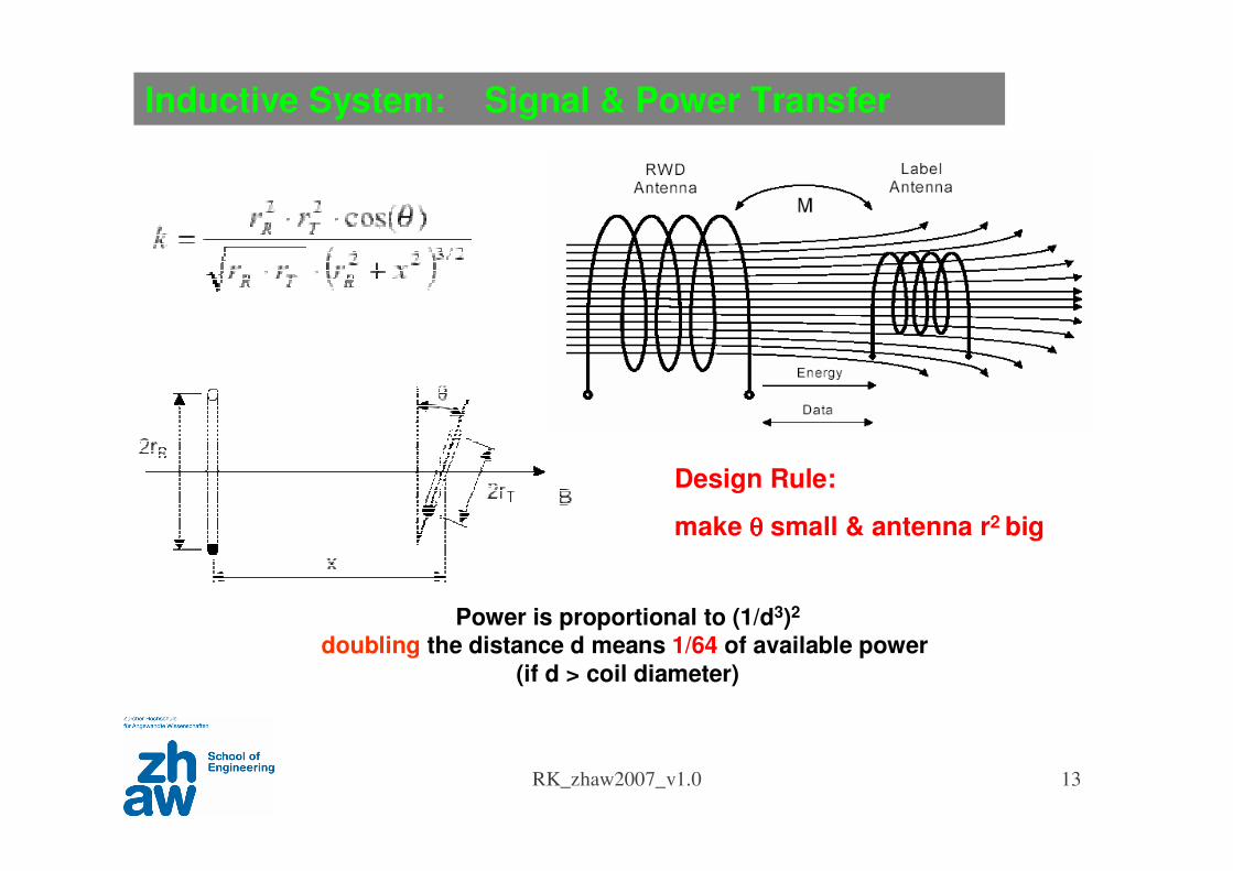
Inductive System: Signal & Power Transfer
Power is proportional to (1/d3)2
doubling the distance d means 1/64 of available power
(if d > coil diameter)
Design Rule:
make θθθθ small & antenna r2 big
RK_zhaw2007_v1.0 14
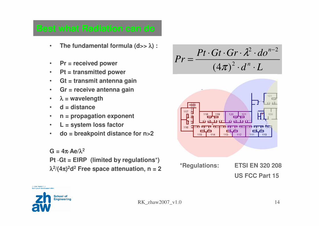
Best what Radiation can do
• The fundamental formula (d>> λλλλ) :
• Pr = received power
• Pt = transmitted power
• Gt = transmit antenna gain
• Gr = receive antenna gain
• λλλλ = wavelength
• d = distance
• n = propagation exponent
• L = system loss factor
• do = breakpoint distance for n>2
G = 4ππππ·Ae/λλλλ2
Pt ·Gt = EIRP (limited by regulations*)
λλλλ2/(4ππππ)2d2 Free space attenuation, n = 2
Ld
doGrGtPtPr
n
n
⋅⋅
⋅⋅⋅⋅=
−
2
22
)4( π
λ
*Regulations: ETSI EN 320 208
US FCC Part 15
RK_zhaw2007_v1.0 15
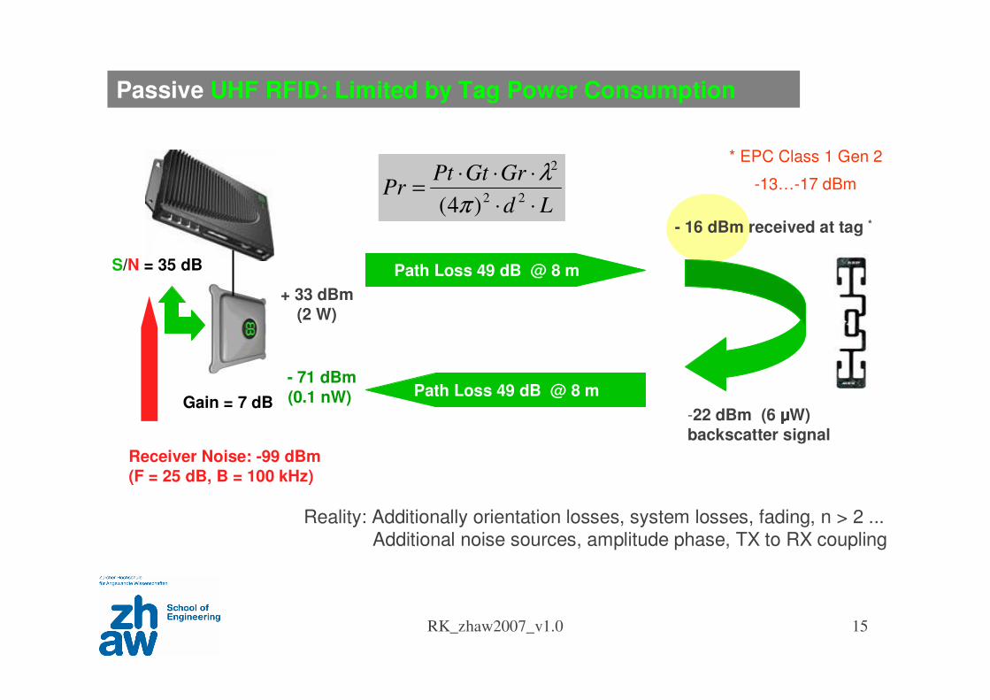
Gain = 7 dB
Path Loss 49 dB @ 8 m
- 16 dBm received at tag *
+ 33 dBm
(2 W)
Path Loss 49 dB @ 8 m- 71 dBm
(0.1 nW)
S/N = 35 dB
-22 dBm (6 μμμμW)
backscatter signal
Ld
GrGtPtPr
⋅⋅
⋅⋅⋅=
22
2
)4( π
λ* EPC Class 1 Gen 2
-13…-17 dBm
Receiver Noise: -99 dBm
(F = 25 dB, B = 100 kHz)
Reality: Additionally orientation losses, system losses, fading, n > 2 ... Additional noise sources, amplitude phase, TX to RX coupling
Passive UHF RFID: Limited by Tag Power Consumption

RK_zhaw2007_v1.0 16
Gain = 7 dB
Path Loss 71 dB @ 100 m
- 38 dBm received at tag *
+ 33 dBm
(2 W)
Path Loss 71 dB @ 100 m- 113 dBm
(5 fW)
S/N = 10 dB
- 42 dBm (50 nW)
backscatter signal
Ld
GrGtPtPr
⋅⋅
⋅⋅⋅=
22
2
)4( π
λ
Receiver Noise: -116 dBm
(F = 8 dB, B = 100 kHz)
Semi-Active UHF RFID: limited by Backward Link
* ZHAW TWD
-50…-54 dBm
Reality: Additionally orientation losses, system losses, fading, n > 2... Additional noise sources, amplitude phase, TX to RX coupling
RK_zhaw2007_v1.0 17
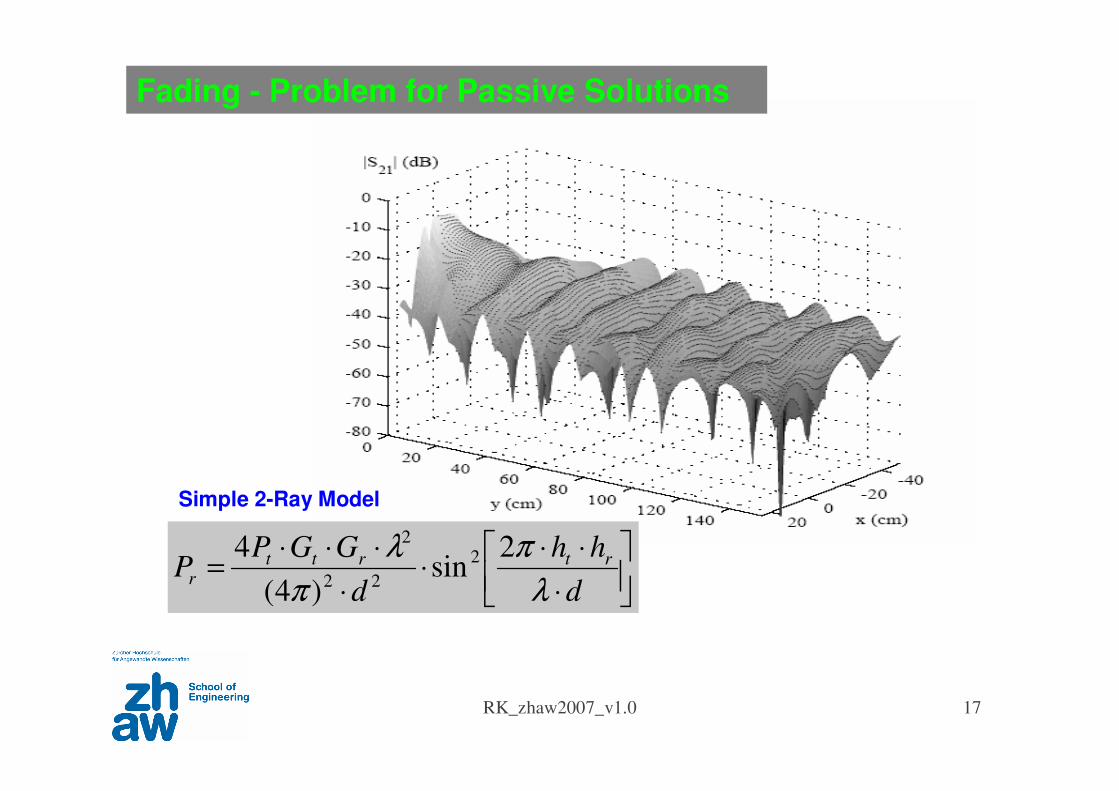
⋅
⋅⋅⋅
⋅
⋅⋅⋅=
d
hh
d
GGPP
rtrtt
r
λ
π
π
λ 2sin
)4(
4 2
22
2
Fading - Problem for Passive Solutions
Simple 2-Ray Model
RFID Tag
RK_zhaw2007_v1.0 19
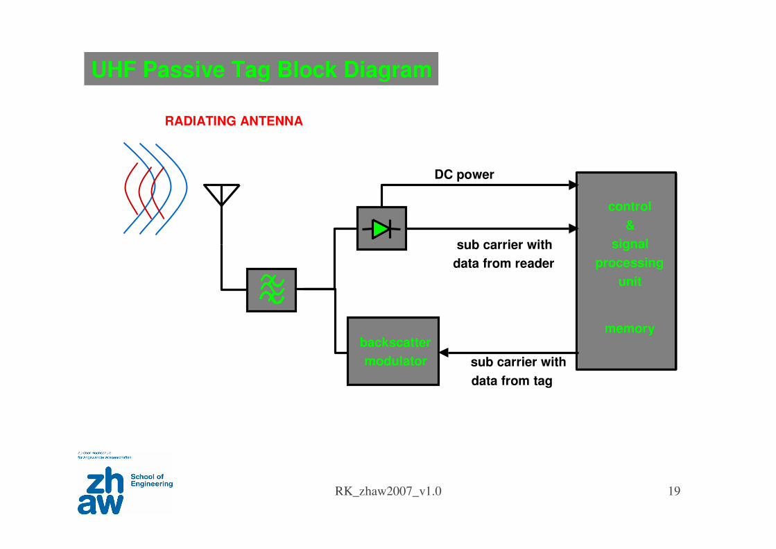
control
&
signal
processing
unit
memorybackscatter
modulator
DC power
sub carrier with
data from reader
sub carrier with
data from tag
RADIATING ANTENNA
UHF Passive Tag Block Diagram
RK_zhaw2007_v1.0 20
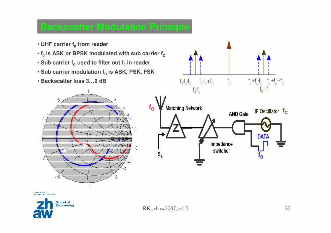
Backscatter Modulation Principle
• UHF carrier f0 from reader
• f0 is ASK or BPSK modulated with sub carrier fC
• Sub carrier fC used to filter out f0 in reader
• Sub carrier modulation fD is ASK, PSK, FSK
• Backscatter loss 3…9 dB
fD
fCfO
RK_zhaw2007_v1.0 21
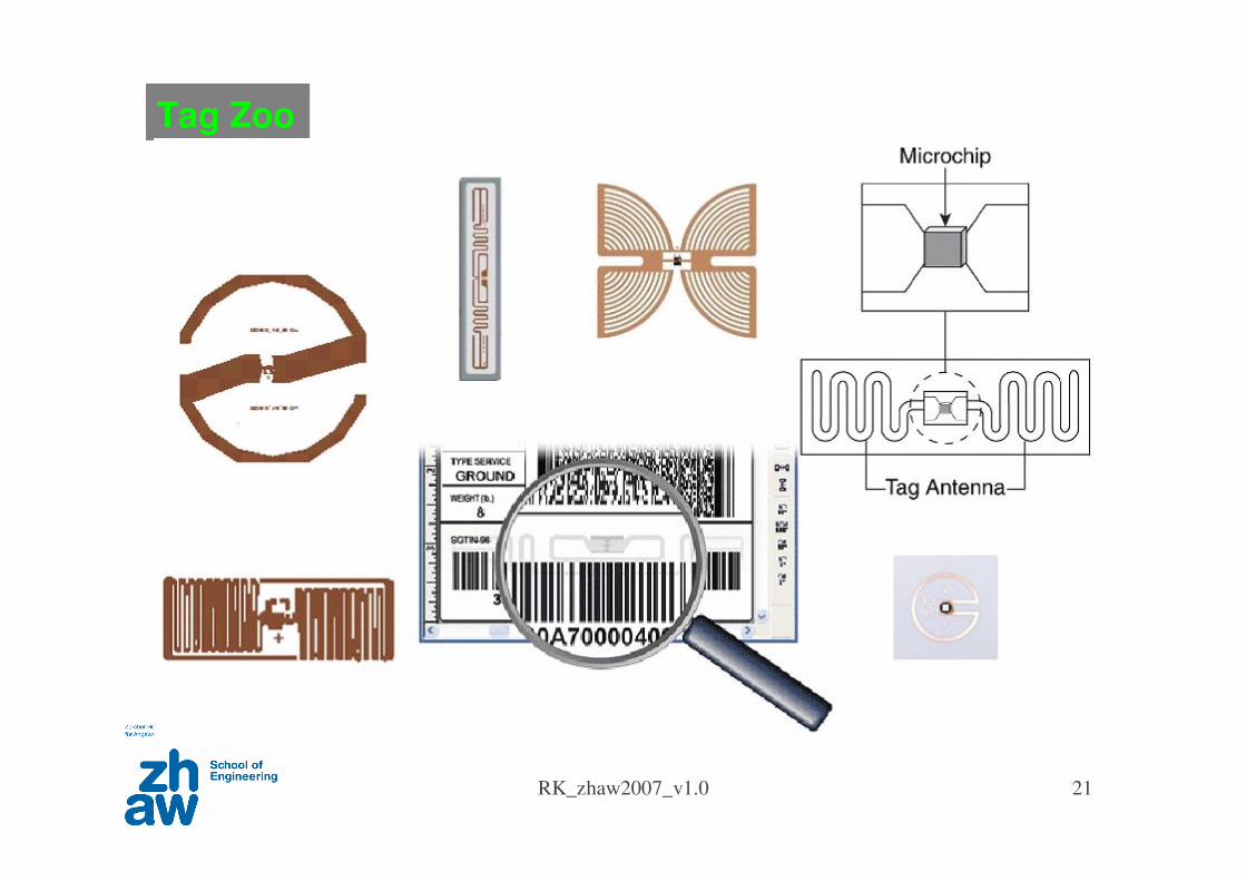
Tag Zoo
RK_zhaw2007_v1.0 22
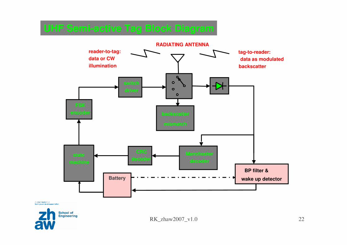
UHF Semi-active Tag Block Diagram
state
machine
CRC
decoderManchester
decoder
BP filter &
wake up detector Battery
backscatter
mismatch
switch
driver
FSK
encoder
reader-to-tag:
data or CW
illumination
tag-to-reader:
data as modulated
backscatter
RADIATING ANTENNA
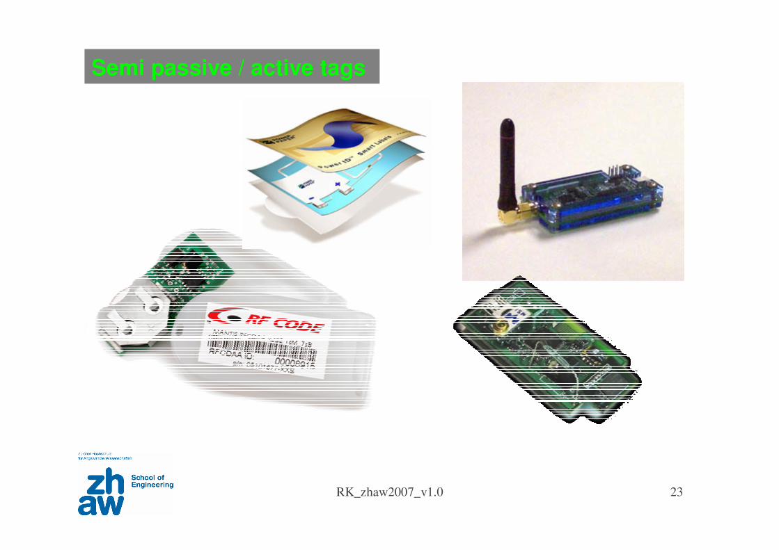
RK_zhaw2007_v1.0 23
Semi passive / active tags
RFID Reader
RK_zhaw2007_v1.0 25
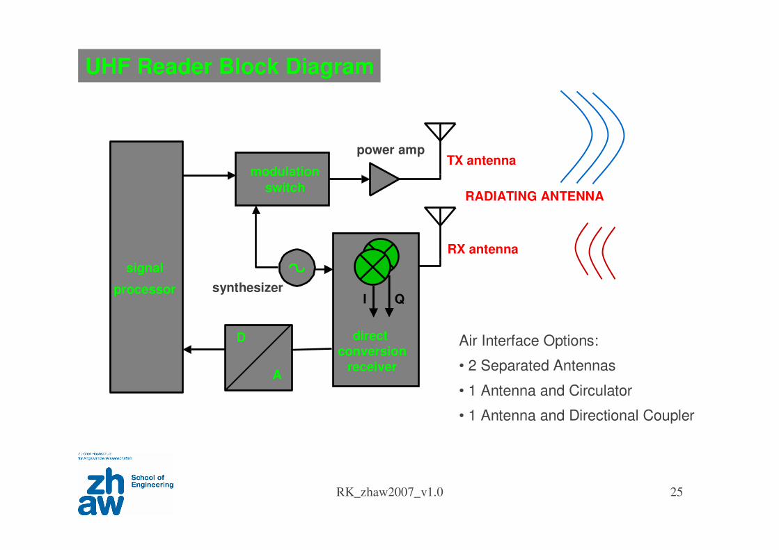
UHF Reader Block Diagram
signal
processor
direct
conversion
receiver
modulation
switch
TX antenna
RX antenna
I Q
RADIATING ANTENNA
synthesizer
Air Interface Options:
• 2 Separated Antennas
• 1 Antenna and Circulator
• 1 Antenna and Directional Coupler
D
A
power amp
RK_zhaw2007_v1.0 26
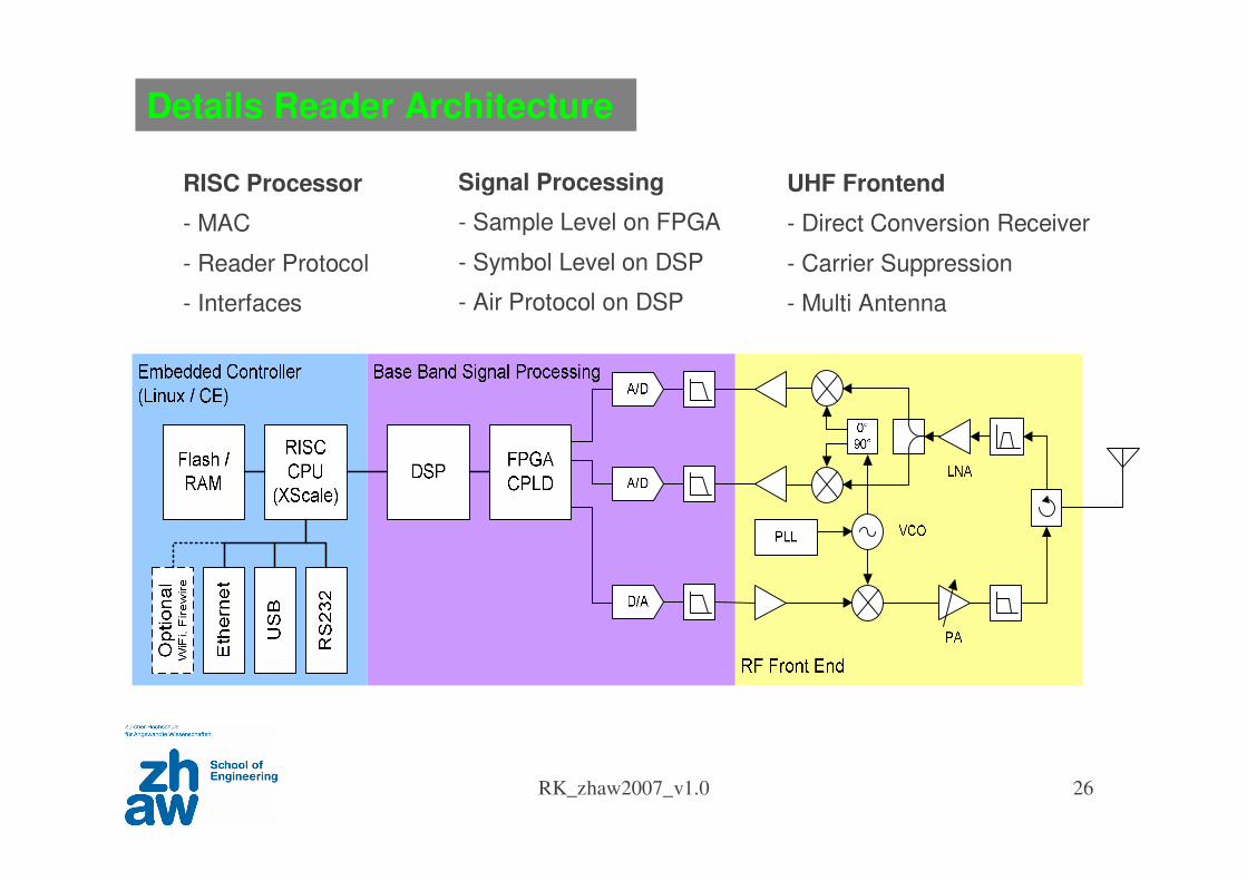
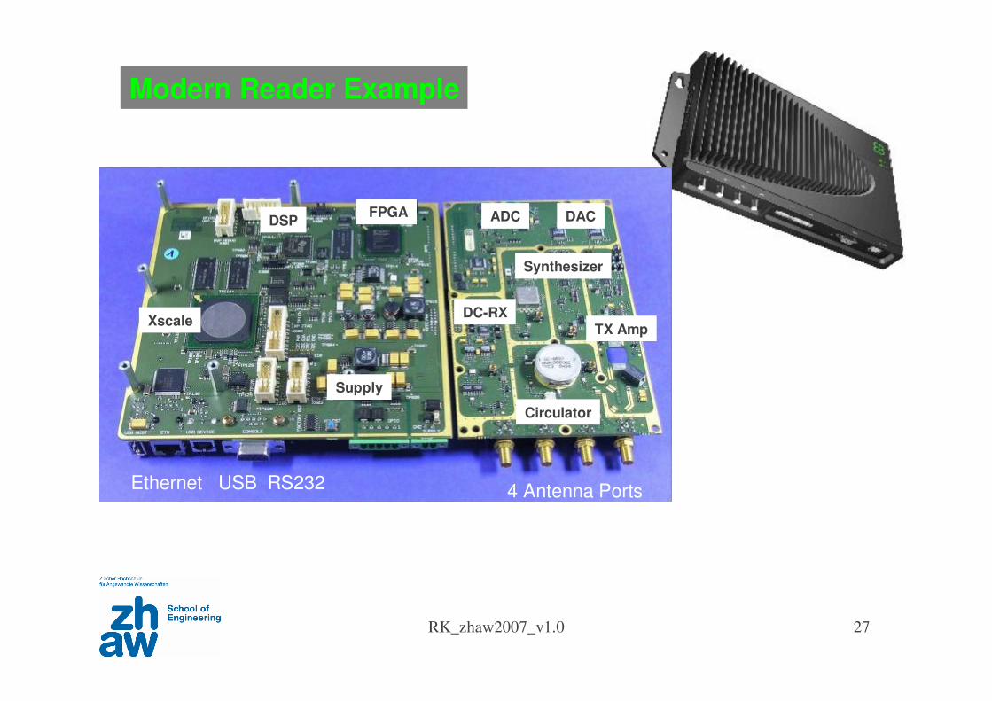
Details Reader Architecture
UHF Frontend
- Direct Conversion Receiver
- Carrier Suppression
- Multi Antenna
Signal Processing
- Sample Level on FPGA
- Symbol Level on DSP
- Air Protocol on DSP
RISC Processor
- MAC
- Reader Protocol
- Interfaces
RK_zhaw2007_v1.0 27
FPGADSP
Xscale
Synthesizer
Circulator
TX Amp
ADC
DC-RX
DAC
Supply
4 Antenna PortsEthernet USB RS232
Modern Reader Example
RK_zhaw2007_v1.0 28
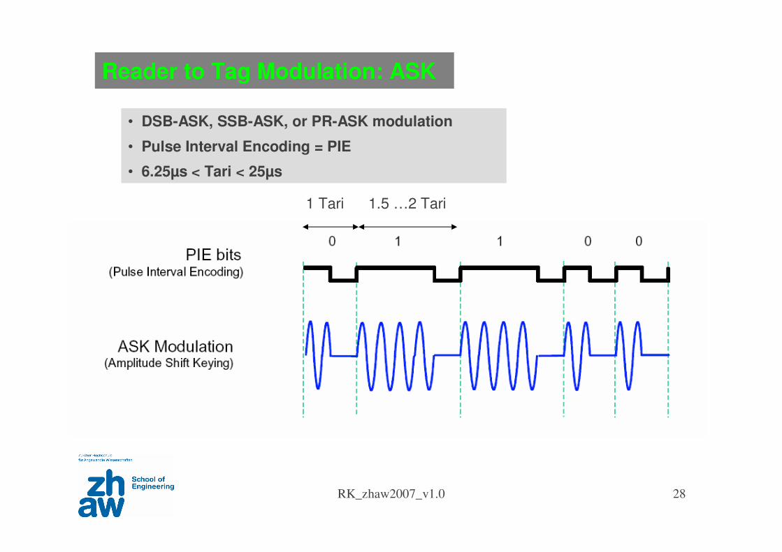
Reader to Tag Modulation: ASK
• DSB-ASK, SSB-ASK, or PR-ASK modulation
• Pulse Interval Encoding = PIE
• 6.25µs < Tari < 25µs
1 Tari 1.5 …2 Tari
RK_zhaw2007_v1.0 29
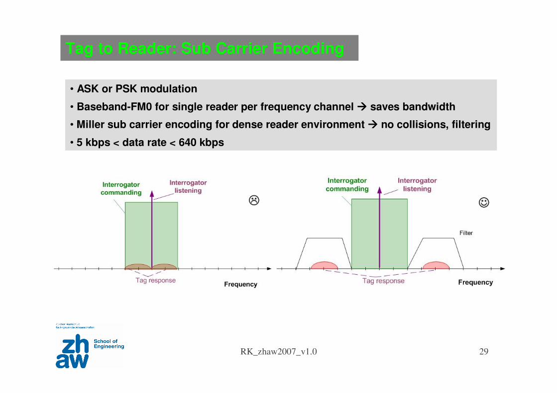
• ASK or PSK modulation
• Baseband-FM0 for single reader per frequency channel saves bandwidth
• Miller sub carrier encoding for dense reader environment no collisions, filtering
• 5 kbps < data rate < 640 kbps
Tag to Reader: Sub Carrier Encoding
RK_zhaw2007_v1.0 30
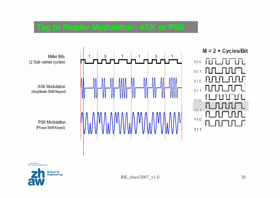
Tag to Reader Modulation: ASK or PSK
UHF Gen2 Protocol
RK_zhaw2007_v1.0 32
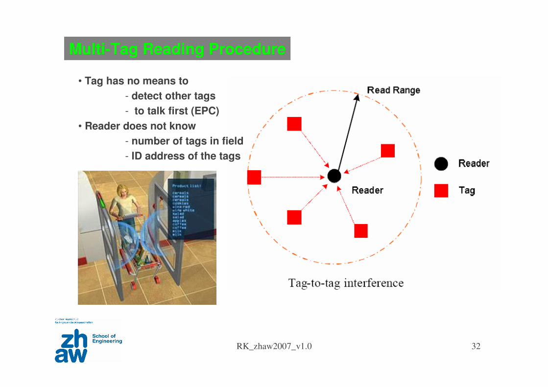
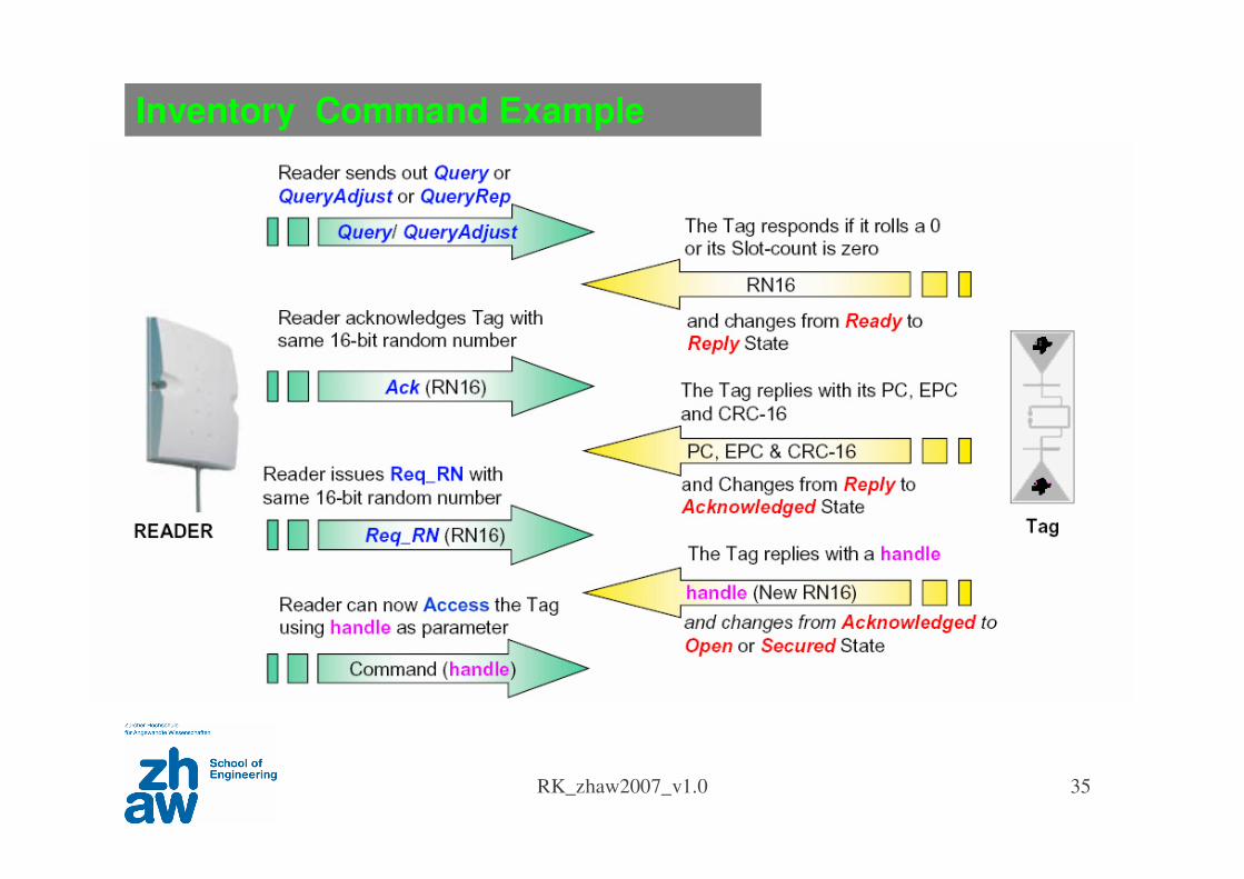
Multi-Tag Reading Procedure
• Tag has no means to
- detect other tags
- to talk first (EPC)
• Reader does not know
- number of tags in field
- ID address of the tags
RK_zhaw2007_v1.0 33
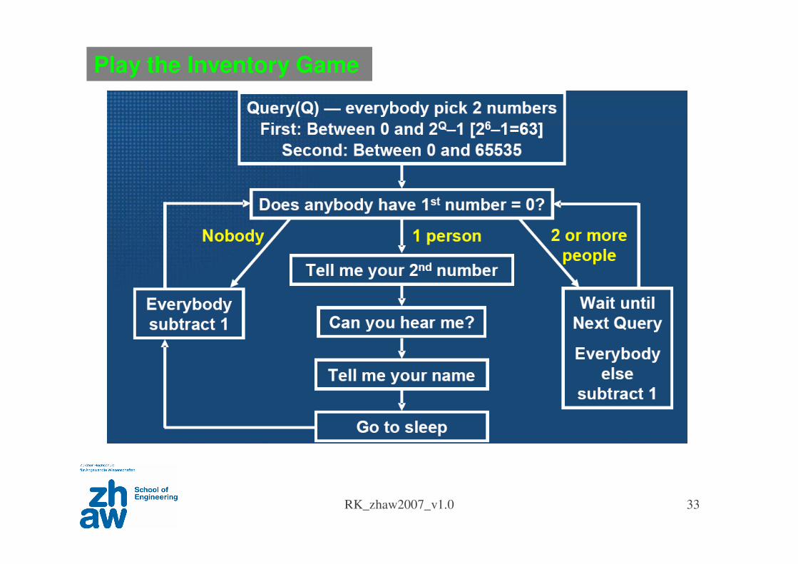
Play the Inventory Game
RK_zhaw2007_v1.0 34
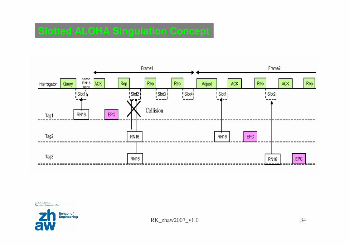
Slotted ALOHA Singulation Concept
same
RN16
sent
RK_zhaw2007_v1.0 35
Inventory Command Example
same
RN16
sent

RFID Antenna and Propagation
RK_zhaw2007_v1.0 37
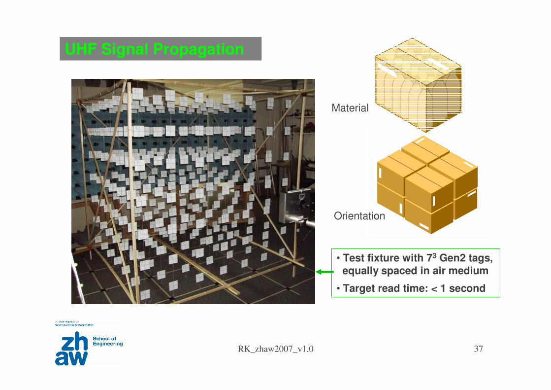
UHF Signal Propagation
• Test fixture with 73 Gen2 tags,
equally spaced in air medium
• Target read time: < 1 second
Material
Orientation
RK_zhaw2007_v1.0 38
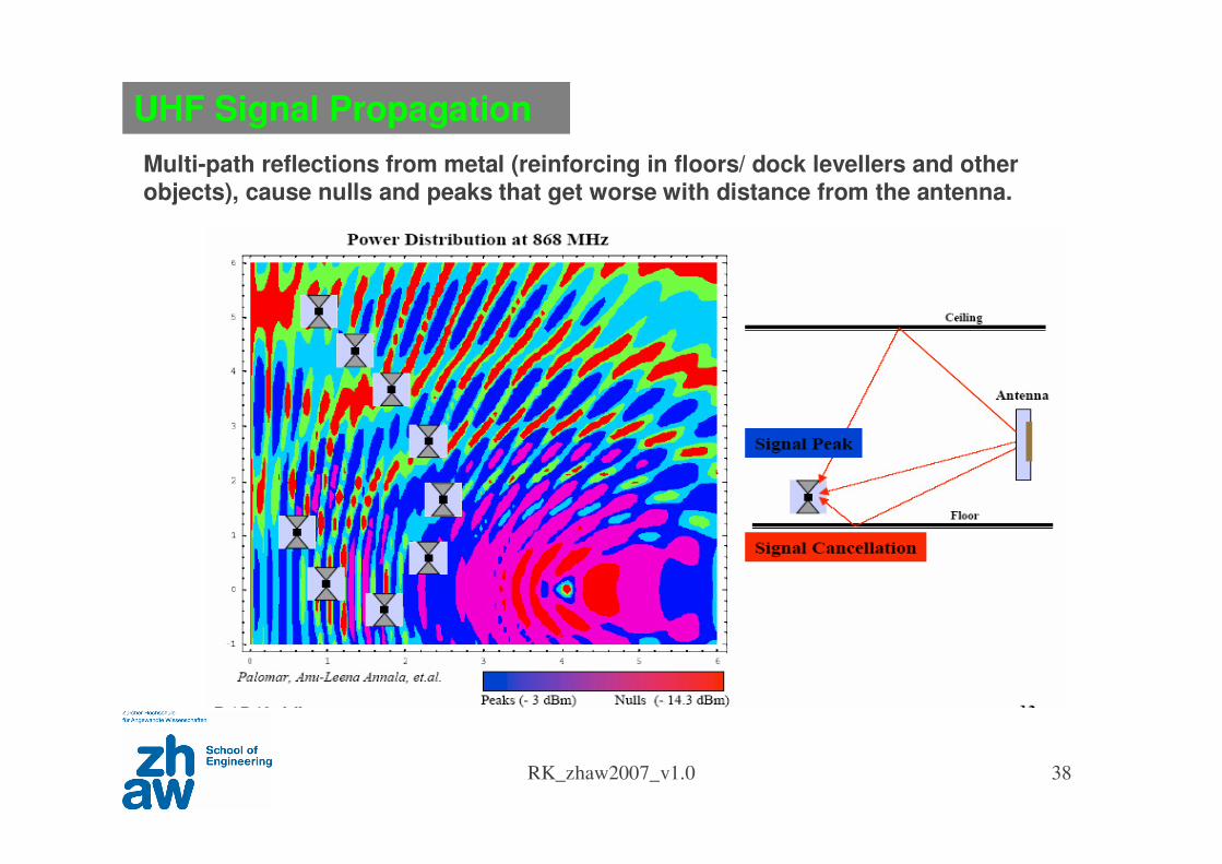
UHF Signal Propagation
Multi-path reflections from metal (reinforcing in floors/ dock levellers and other objects), cause nulls and peaks that get worse with distance from the antenna.
RK_zhaw2007_v1.0 39
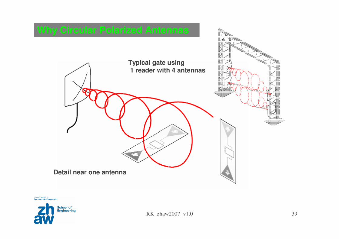
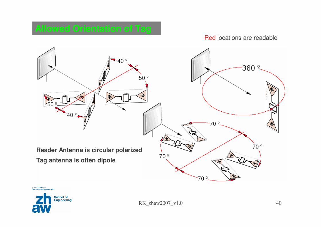
Why Circular Polarized Antennas
Typical gate using1 reader with 4 antennas
Detail near one antenna
RK_zhaw2007_v1.0 40
Allowed Orientation of Tag
Reader Antenna is circular polarized
Tag antenna is often dipole
Red locations are readable

RFID Systems
RK_zhaw2007_v1.0 42
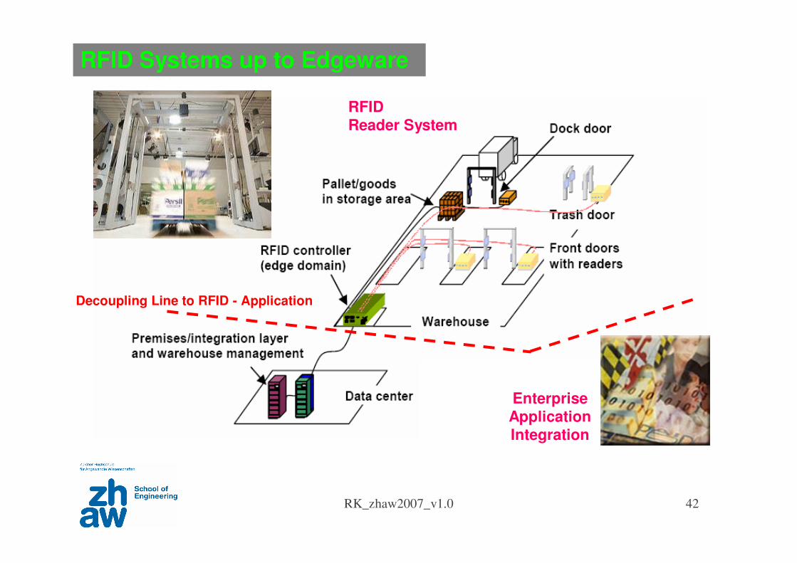
RFID Systems up to Edgeware
RFID Reader System
Enterprise Application Integration
Decoupling Line to RFID - Application
RK_zhaw2007_v1.0 43
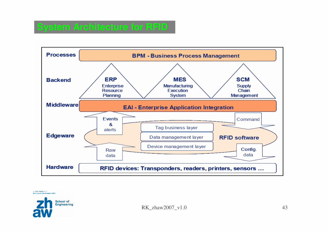
System Architecture for RFID
RK_zhaw2007_v1.0 44
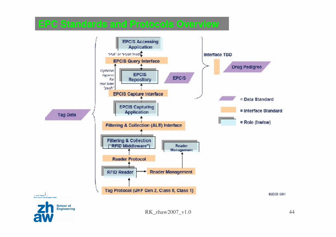
EPC Standards and Protocols Overview
Hardware
Edgeware
Middleware
RK_zhaw2007_v1.0 45
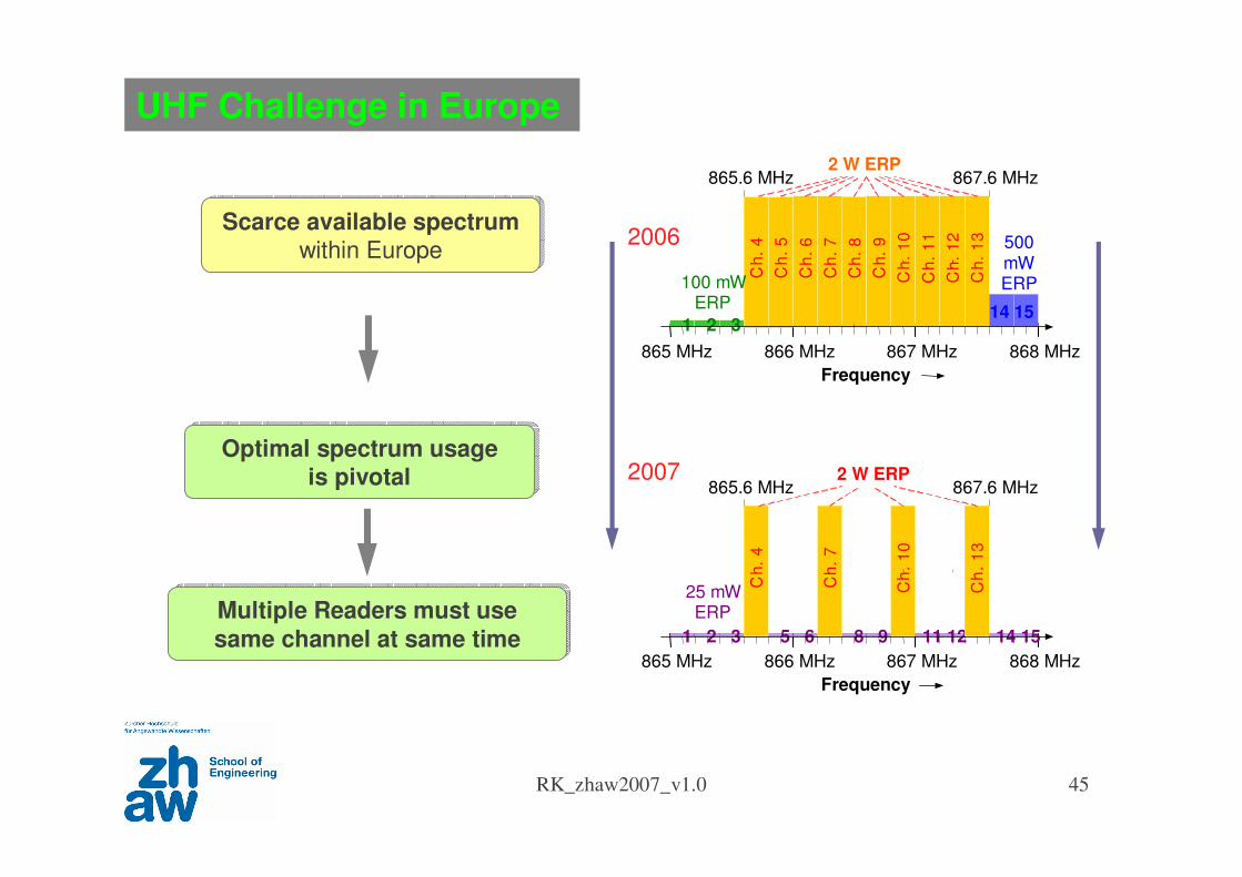
UHF Challenge in Europe
Optimal spectrum usage is pivotal
Optimal spectrum usage is pivotal
Scarce available spectrumwithin Europe
Scarce available spectrumwithin Europe
865 MHz 866 MHz 867 MHz 868 MHz
865.6 MHz 867.6 MHz
Ch
.4
Ch
.5
Ch
.6
Ch
.7
Ch
.8
Ch
.9
Ch
.1
0
Ch
.1
1
Ch
.1
2
Ch
.1
3
Frequency
100 mWERP
500mWERP
2 W ERP
1 2 314 15
14 155 6 8 9 11 121 2 3
865 MHz 866 MHz 867 MHz 868 MHz
865.6 MHz 867.6 MHz
Ch
.4
Ch
.7
Ch
.1
0
Ch
.1
3
Frequency
25 mWERP
2 W ERP
Multiple Readers must use
same channel at same timeMultiple Readers must use
same channel at same time
2007
2006
RK_zhaw2007_v1.0 46
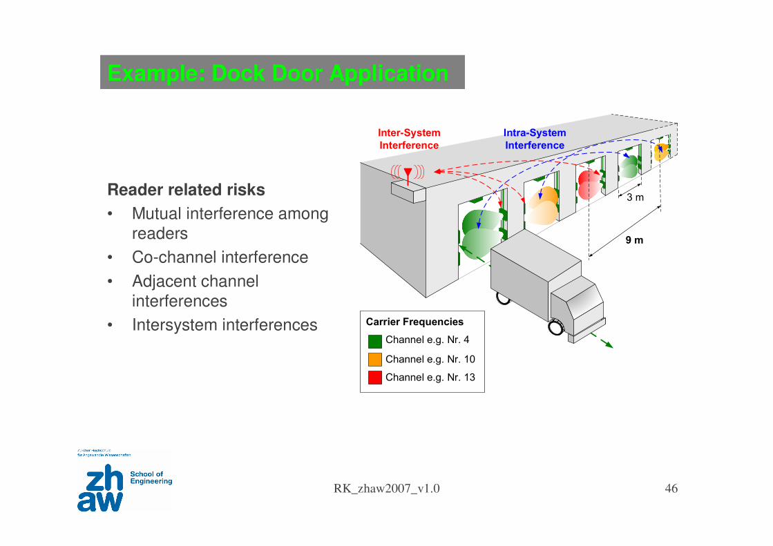
Example: Dock Door Application
Reader related risks
• Mutual interference among
readers
• Co-channel interference
• Adjacent channel
interferences
• Intersystem interferences
3 m
Intra-System
Interference
Channel e.g. Nr. 4
Channel e.g. Nr. 10
Carrier Frequencies
Inter-System
Interference
9 m
Channel e.g. Nr. 13
RK_zhaw2007_v1.0 47
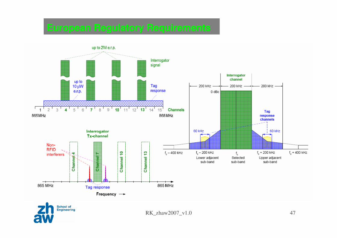
European Regulatory Requirements
RK_zhaw2007_v1.0 48
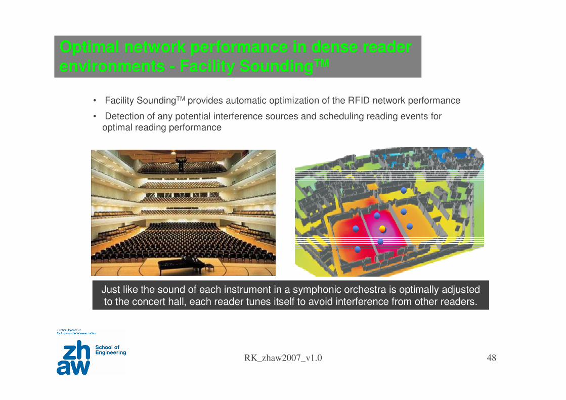
Optimal network performance in dense reader environments - Facility SoundingTM
Just like the sound of each instrument in a symphonic orchestra is optimally adjusted to the concert hall, each reader tunes itself to avoid interference from other readers.
• Facility SoundingTM provides automatic optimization of the RFID network performance
• Detection of any potential interference sources and scheduling reading events for optimal reading performance
Toward Internet of Things
RK_zhaw2007_v1.0 50
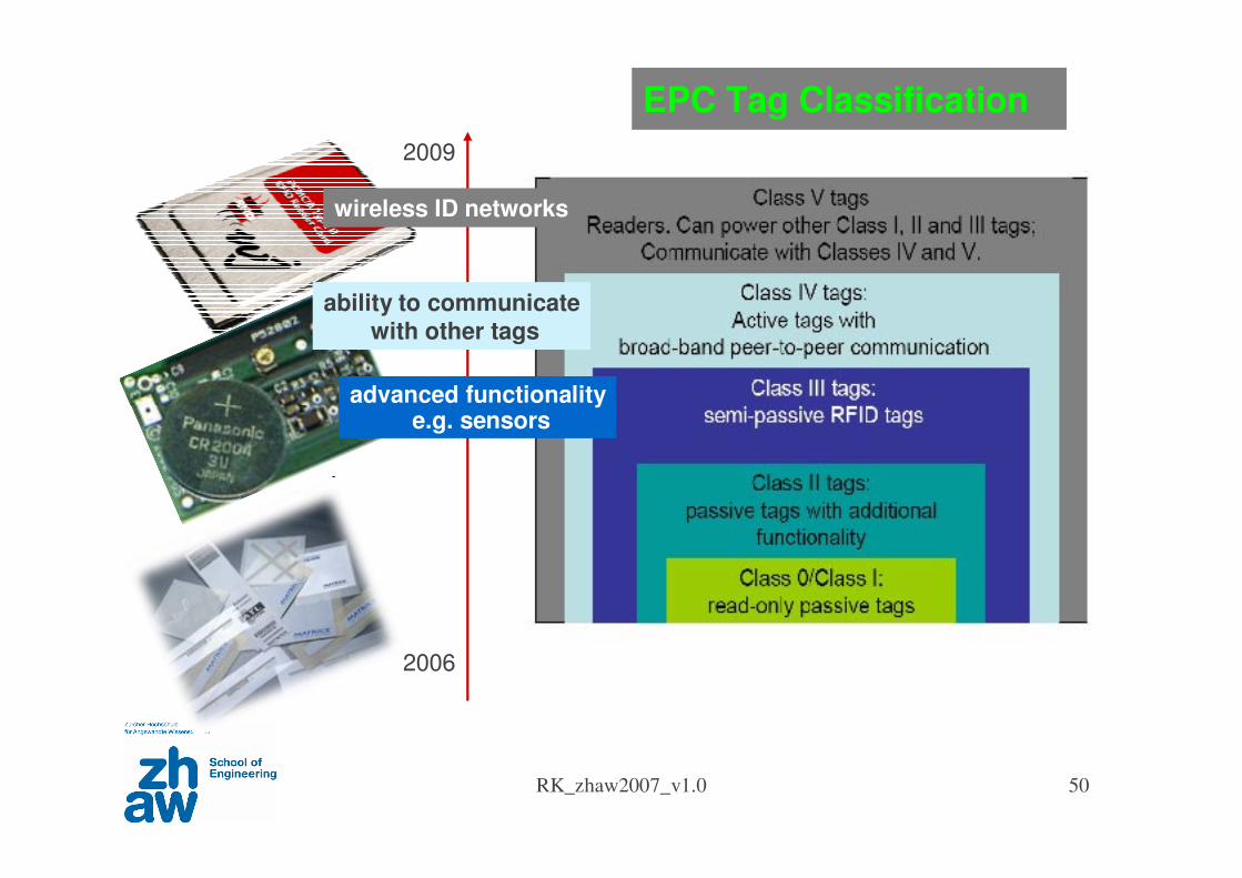
advanced functionalitye.g. sensors
ability to communicatewith other tags
wireless ID networks
2006
2009
EPC Tag Classification
RK_zhaw2007_v1.0 51
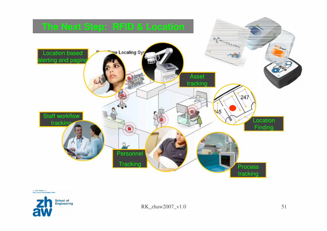
The Next Step: RFID & Location
Staff workflow tracking
Process tracking
Location based alerting and paging
Personnel
Tracking
Asset tracking
Location Finding
RK_zhaw2007_v1.0 52
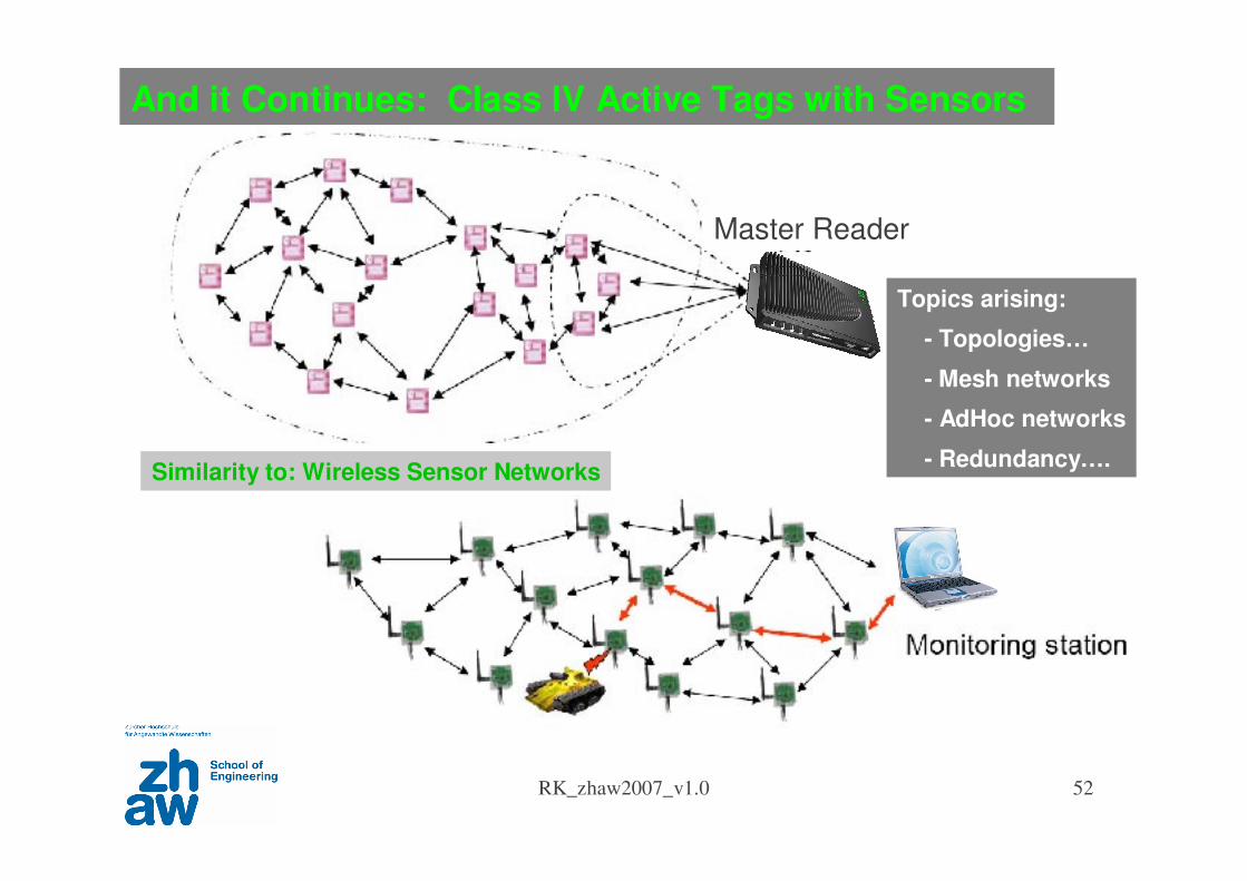
And it Continues: Class IV Active Tags with Sensors
Similarity to: Wireless Sensor Networks
Topics arising:
- Topologies…
- Mesh networks
- AdHoc networks
- Redundancy….
Master Reader
RK_zhaw2007_v1.0 53
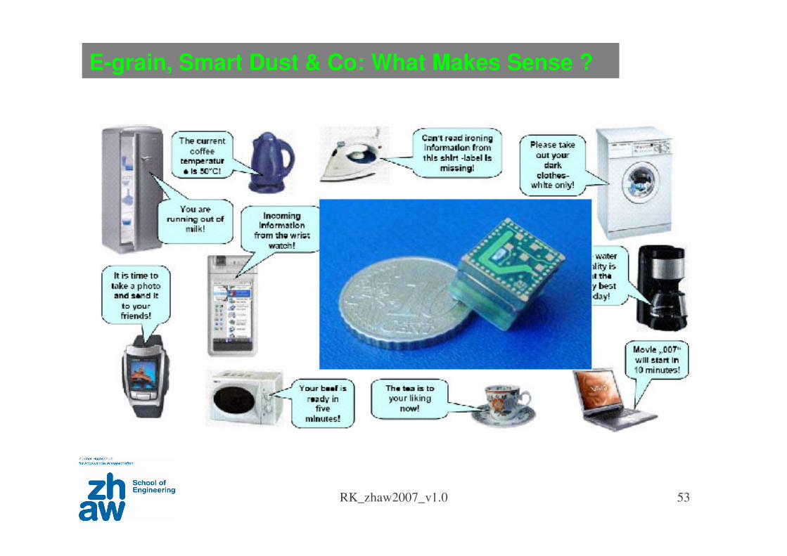
E-grain, Smart Dust & Co: What Makes Sense ?
RK_zhaw2007_v1.0 54
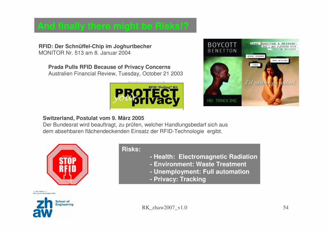
And finally there might be Risks!?
Switzerland, Postulat vom 9. März 2005
Der Bundesrat wird beauftragt, zu prüfen, welcher Handlungsbedarf sich aus
dem absehbaren flächendeckenden Einsatz der RFID-Technologie ergibt.
RFID: Der Schnüffel-Chip im JoghurtbecherMONITOR Nr. 513 am 8. Januar 2004
Prada Pulls RFID Because of Privacy Concerns
Australien Financial Review, Tuesday, October 21 2003
Risks:- Health: Electromagnetic Radiation- Environment: Waste Treatment- Unemployment: Full automation - Privacy: Tracking
RK_zhaw2007_v1.0 55
Internet of Things Will Move the World
Questions ?