Embed Size (px)
Citation preview
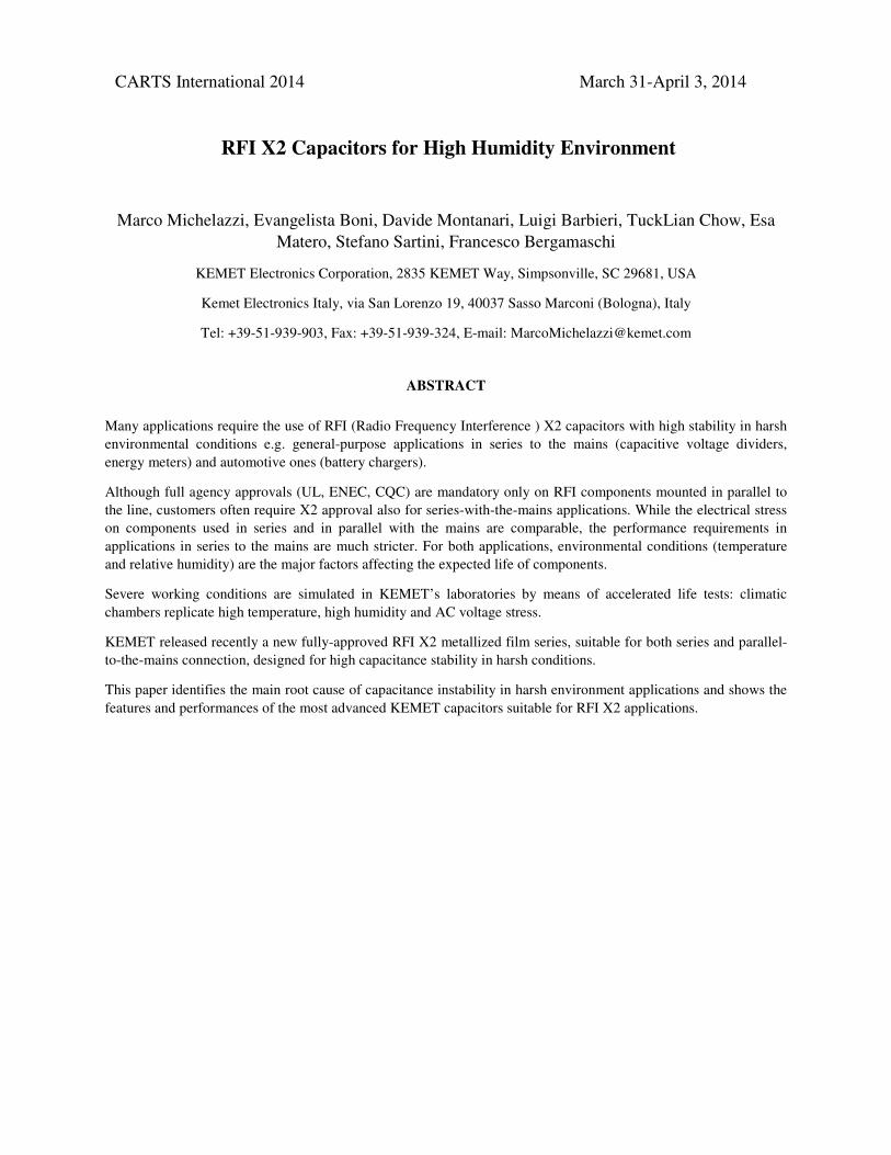
RFI X2 Capacitors for High Humidity Environment
Marco Michelazzi, Evangelista Boni, Davide Montanari, Luigi Barbieri, TuckLian Chow, Esa
Matero, Stefano Sartini, Francesco Bergamaschi
KEMET Electronics Corporation, 2835 KEMET Way, Simpsonville, SC 29681, USA
Kemet Electronics Italy, via San Lorenzo 19, 40037 Sasso Marconi (Bologna), Italy
Tel: +39-51-939-903, Fax: +39-51-939-324, E-mail: [email protected]
ABSTRACT
Many applications require the use of RFI (Radio Frequency Interference ) X2 capacitors with high stability in harsh
environmental conditions e.g. general-purpose applications in series to the mains (capacitive voltage dividers,
energy meters) and automotive ones (battery chargers).
Although full agency approvals (UL, ENEC, CQC) are mandatory only on RFI components mounted in parallel to
the line, customers often require X2 approval also for series-with-the-mains applications. While the electrical stress
on components used in series and in parallel with the mains are comparable, the performance requirements in
applications in series to the mains are much stricter. For both applications, environmental conditions (temperature
and relative humidity) are the major factors affecting the expected life of components.
Severe working conditions are simulated in KEMET’s laboratories by means of accelerated life tests: climatic
chambers replicate high temperature, high humidity and AC voltage stress.
KEMET released recently a new fully-approved RFI X2 metallized film series, suitable for both series and parallel-
to-the-mains connection, designed for high capacitance stability in harsh conditions.
This paper identifies the main root cause of capacitance instability in harsh environment applications and shows the
features and performances of the most advanced KEMET capacitors suitable for RFI X2 applications.
CARTS International 2014 March 31-April 3, 2014
INTRODUCTION
AC filtering capacitors have the task of reducing the high-frequency harmonics overlapped to the fundamental
network frequency (50-60 Hz). Usually, the first significant harmonic amplitude lies between 2.5 and 6 kHz,
depending on the specific equipment the filter is used upon.
The RFI film capacitors used in AC filtering are approved by ENEC, UL/cUL and CQC, in this paper we consider to
use the metallized polypropylene film in wound technology.
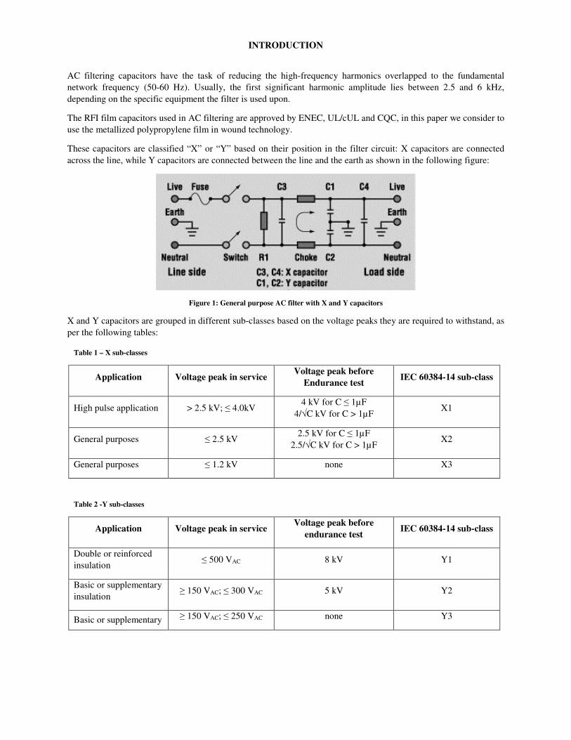
These capacitors are classified “X” or “Y” based on their position in the filter circuit: X capacitors are connected
across the line, while Y capacitors are connected between the line and the earth as shown in the following figure:
Figure 1: General purpose AC filter with X and Y capacitors
X and Y capacitors are grouped in different sub-classes based on the voltage peaks they are required to withstand, as
per the following tables:
Table 1 – X sub-classes
Application Voltage peak in service Voltage peak before
Endurance test IEC 60384-14 sub-class
High pulse application > 2.5 kV; ≤ 4.0kV 4 kV for C ≤ 1µF
4/√C kV for C > 1µF X1
General purposes ≤ 2.5 kV 2.5 kV for C ≤ 1µF
2.5/√C kV for C > 1µF X2
General purposes ≤ 1.2 kV none X3
Table 2 -Y sub-classes
Application Voltage peak in service Voltage peak before
endurance test IEC 60384-14 sub-class
Double or reinforced
insulation ≤ 500 VAC 8 kV Y1
Basic or supplementary
insulation ≥ 150 VAC; ≤ 300 VAC 5 kV Y2
Basic or supplementary ≥ 150 VAC; ≤ 250 VAC none Y3
insulation
Basic or supplementary
insulation < 150 VAC 2.5 kV Y4
The self-healing property of metallized film dielectrics (their ability to self-regenerate an internal drop of insulation
resistance) ensures a safe failure mode in AC filtering applications, where electrical noise and peak voltages are
added repeatedly or occasionally to the fundamental frequency. When the self-healing operates, the temporary
breakdown it creates results in a “clearing” of a metallized dielectric small area, causing a minor loss of Capacitance
and the restoration of the capacitor’s initial electrical properties.
Polypropylene is the best material in terms of self-healing thanks to its all-aliphatic structure. Metallization material
and thickness also play a significant role though, and in X and Y RFI capacitors they are specifically designed to
maximize the self-healing performance. Nevertheless, the design choices aimed towards self-healing may make
these kind of capacitors more susceptible than others to loss of Capacitance when exposed to extreme environmental
conditions.
X-capacitors are generally mounted in parallel with the mains, with the purpose of filtering electromagnetic
interference, both from the mains and the equipment, and of protecting the appliance from voltage spikes. In this
application usually the customers use capacitors with large nominal tolerance (+/-20%). In recent years high
capacitance stability and low tolerance have become a key feature for X capacitors, due to the development of more
and more applications in series to the mains, in which the capacitor itself has the role of feeding AC voltage to the
circuit, via a capacitive divider.
This need was followed by the introduction of the THB as qualification test for X capacitors. THB stands for
Temperature Humidity Bias and is conducted for 1,000 hours at 85°C/85% relative humidity (RH), applying 240VAC
(for X2 capacitors). Target performance is a capacitance decrease no larger than 10%.
THB is an accelerated endurance test and, therefore, stresses the components more than real-world applications. For
this reason, it is important to integrate the test results with a predictive model for an easy and reliable prediction of
end-user-application-condition performances.
In this paper, the capacitance loss mechanisms in harsh conditions are analysed and a model for life prediction is
provided for KEMET’s new X2 heavy duty series.
2 - EXPERIMENTAL METHODS AND INSTRUMENTS
Here is the description of the instruments, tools and methods used during the performed measurements. For each of
them, the specific measured parameters are indicated.
Agilent E4980, HP4284A Precision LCR meter and HP4192A Impedance Analyzer (1 kHz and 1 VRMS):
capacitance (C), dissipation factor (tg delta), equivalent series resistance (ESR).
Radio Meter IM6 Megaohmeter (1 - 999 V): insulation resistance (IR).
Heraeus Mod. UT6060 Oven: operational life DC and high temperature exposure.
Heraeus VLK, Heraeus HC2020 and Weiss 180/40 Environmental Test Chamber: temperature varied in the
range 40-85°C, absolute humidity varied in the range 45-600 g/Kg.
Bertan 225 High Voltage Power Supply: operational life DC.
Kikusui TOS9201: first break-down voltage (FBDV)
3 - FOREWORD ON SUPPRESSORS APPLICATIONS AND RELATED CAPACITORS DESIGN
3.1 - Standard requirements
As highlighted in the introduction, the main function of suppressor capacitors is filtering the noise of the network
and protecting the appliances and the users from peak voltages mainly due to the following potential causes:
� Lightnings
� Power commutations
� Parasitic interferences
In case of any of the above events, the capacitor must be able to satisfy the main international standards, e.g.:
� IEC 60384-14 (ENEC)
� UL 60384-14
� cUL Canada E60384-14
� CQC (China Quality Certification Center)
The main tests and requirement of the IEC60384-14 standard are:
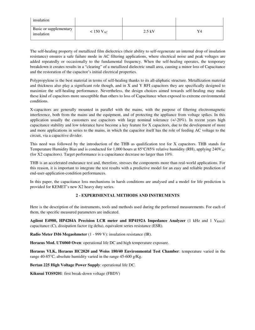
� IMPULSE VOLTAGE TEST
2.5 kV for X2 components with the following voltage waveforms normalized for lightings
Figure 2: Impulse voltage test waveform
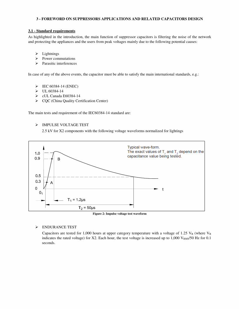
� ENDURANCE TEST
Capacitors are tested for 1,000 hours at upper category temperature with a voltage of 1.25 VR (where VR
indicates the rated voltage) for X2. Each hour, the test voltage is increased up to 1,000 VRMS/50 Hz for 0.1
seconds.
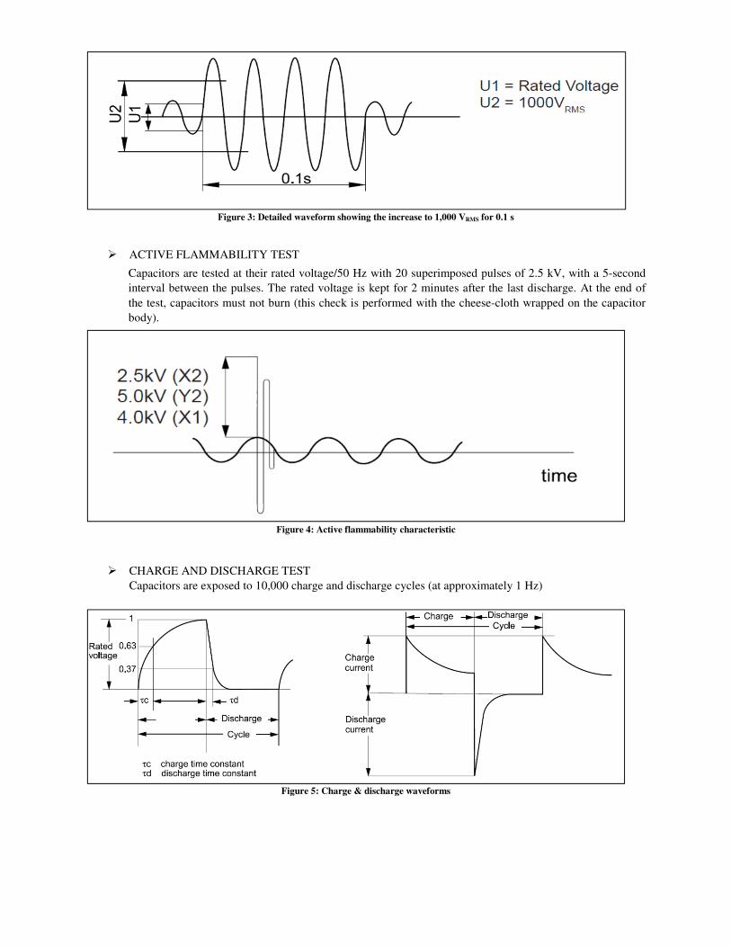
Figure 3: Detailed waveform showing the increase to 1,000 VRMS for 0.1 s
� ACTIVE FLAMMABILITY TEST
Capacitors are tested at their rated voltage/50 Hz with 20 superimposed pulses of 2.5 kV, with a 5-second
interval between the pulses. The rated voltage is kept for 2 minutes after the last discharge. At the end of
the test, capacitors must not burn (this check is performed with the cheese-cloth wrapped on the capacitor
body).
Figure 4: Active flammability characteristic
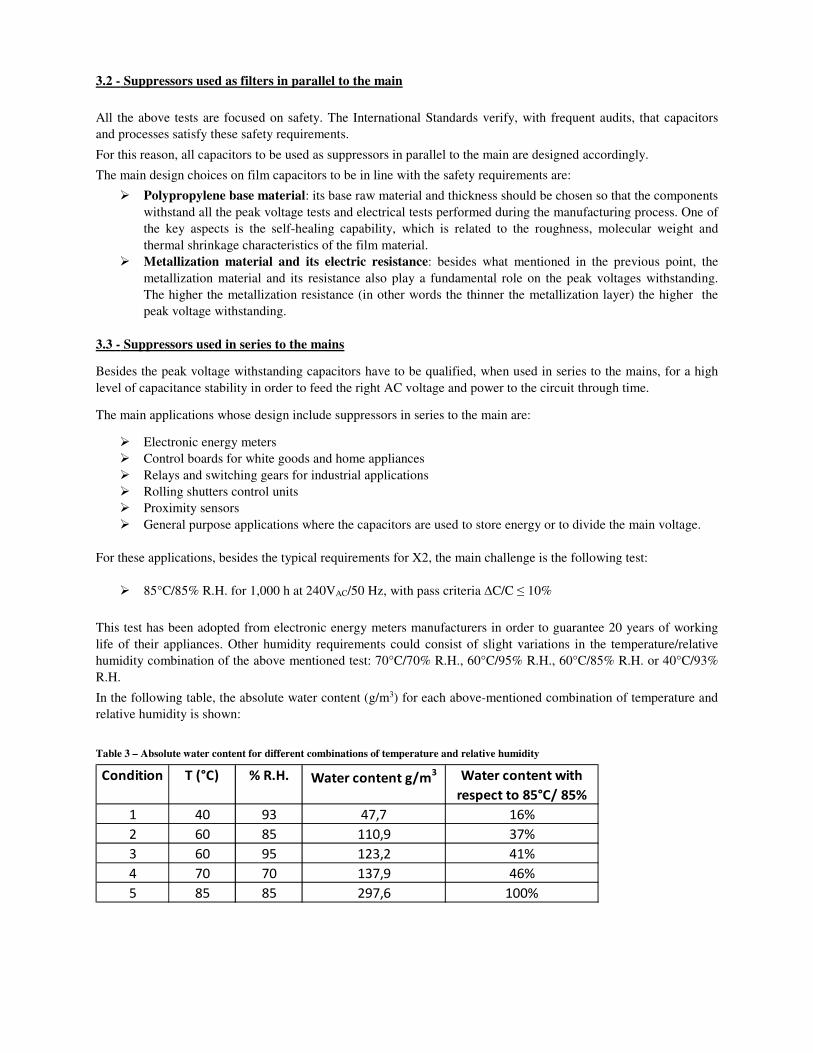
� CHARGE AND DISCHARGE TEST
Capacitors are exposed to 10,000 charge and discharge cycles (at approximately 1 Hz)
Figure 5: Charge & discharge waveforms
3.2 - Suppressors used as filters in parallel to the main
All the above tests are focused on safety. The International Standards verify, with frequent audits, that capacitors
and processes satisfy these safety requirements.
For this reason, all capacitors to be used as suppressors in parallel to the main are designed accordingly.
The main design choices on film capacitors to be in line with the safety requirements are:
� Polypropylene base material: its base raw material and thickness should be chosen so that the components
withstand all the peak voltage tests and electrical tests performed during the manufacturing process. One of
the key aspects is the self-healing capability, which is related to the roughness, molecular weight and
thermal shrinkage characteristics of the film material.
� Metallization material and its electric resistance: besides what mentioned in the previous point, the
metallization material and its resistance also play a fundamental role on the peak voltages withstanding.
The higher the metallization resistance (in other words the thinner the metallization layer) the higher the
peak voltage withstanding.
3.3 - Suppressors used in series to the mains
Besides the peak voltage withstanding capacitors have to be qualified, when used in series to the mains, for a high
level of capacitance stability in order to feed the right AC voltage and power to the circuit through time.
The main applications whose design include suppressors in series to the main are:
� Electronic energy meters
� Control boards for white goods and home appliances
� Relays and switching gears for industrial applications
� Rolling shutters control units
� Proximity sensors
� General purpose applications where the capacitors are used to store energy or to divide the main voltage.
For these applications, besides the typical requirements for X2, the main challenge is the following test:
� 85°C/85% R.H. for 1,000 h at 240VAC/50 Hz, with pass criteria ∆C/C ≤ 10%
This test has been adopted from electronic energy meters manufacturers in order to guarantee 20 years of working
life of their appliances. Other humidity requirements could consist of slight variations in the temperature/relative
humidity combination of the above mentioned test: 70°C/70% R.H., 60°C/95% R.H., 60°C/85% R.H. or 40°C/93%
R.H.
In the following table, the absolute water content (g/m3) for each above-mentioned combination of temperature and
relative humidity is shown:
Table 3 – Absolute water content for different combinations of temperature and relative humidity
Condition T (°C) % R.H. Water content g/m3 Water content with
respect to 85°C/ 85%
1 40 93 47,7 16%
2 60 85 110,9 37%
3 60 95 123,2 41%
4 70 70 137,9 46%
5 85 85 297,6 100%
The chart above shows that the absolute water content of the 85°C/85% R.H. condition is 6 times larger than the
40°C/93% R.H. one, the latter being usually the one mentioned in the international standards of RFI capacitors. For
this reason, these standards do not cover all the requirements of applications where high level of capacitance
stability is required.
Another meaningful difference between the requirements of the international standards of the RFI capacitors and
real-world applications (e.g. electronic energy meters) consists in the missing requirement of a VAC waveform
applied during the humidity test. In the real environment both stresses (VAC and 85°C/85% R.H.) are present. This
aspect increases the magnitude of the environmental stress on the capacitors, because of the positive synergism
between voltage and humidity.
The requirement of high capacitance stability should be considered during the design of these RFI capacitors, for
example in the selection of film base, metallization resistance and all materials that give an enclosure of the internal
film element. All these materials usually have special features that increase the cost of the capacitors. During the
selection of suppressors, designers should require the real-application-requirement level of humidity withstanding
capability, in order to find the right capacitor at the proper cost.
In general, the film base material should have good self-healing capability but also show a good behaviour under
tough humidity conditions: this means that some film base materials are not suitable at all for these applications.
The metallization resistance selection has an important role in the right compromise between safety aspects and
capacitance stability. As previously stated, the higher the resistance value, the higher the performance on peak
voltage withstanding, but the lower the capacitance stability in humidity conditions. Increasing the resistance,
without modifying the morphological structure of the metal layer, means reducing the thickness of the metal that
could be oxidized during the electrochemical corrosion phenomenon.
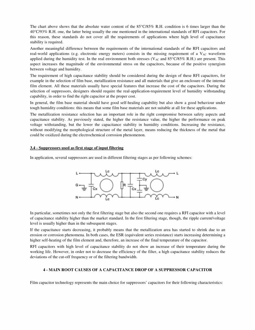
3.4 - Suppressors used as first stage of input filtering
In application, several suppressors are used in different filtering stages as per following schemes:
In particular, sometimes not only the first filtering stage but also the second one requires a RFI capacitor with a level
of capacitance stability higher than the market standard. In the first filtering stage, though, the ripple current/voltage
level is usually higher than in the subsequent stages.
If the capacitance starts decreasing, it probably means that the metallization area has started to shrink due to an
erosion or corrosion phenomena. In both cases, the ESR (equivalent series resistance) starts increasing determining a
higher self-heating of the film element and, therefore, an increase of the final temperature of the capacitor.
RFI capacitors with high level of capacitance stability do not show an increase of their temperature during the
working life. However, in order not to decrease the efficiency of the filter, a high capacitance stability reduces the
deviations of the cut-off frequency or of the filtering bandwidth.
4 - MAIN ROOT CAUSES OF A CAPACITANCE DROP OF A SUPPRESSOR CAPACITOR
Film capacitor technology represents the main choice for suppressors’ capacitors for their following characteristics:
� The self-healing characteristic of the film base material guarantees high reliability in the overall process
chain of appliances, starting from the manufacturing of the capacitors up to the working of the final
equipment in the market when special safety requirements are mandatory. Other technologies can build
reliable capacitors, but issues can happen after the manufacturing as during the mounting of PCBs or
appliances. Furthermore, the failure mode of film capacitors is a capacitance drop or an open-circuit mode
and this makes them very suitable where safety and reliability are required.
� The low cost of film suppressors has been a key for the increase of their production volumes
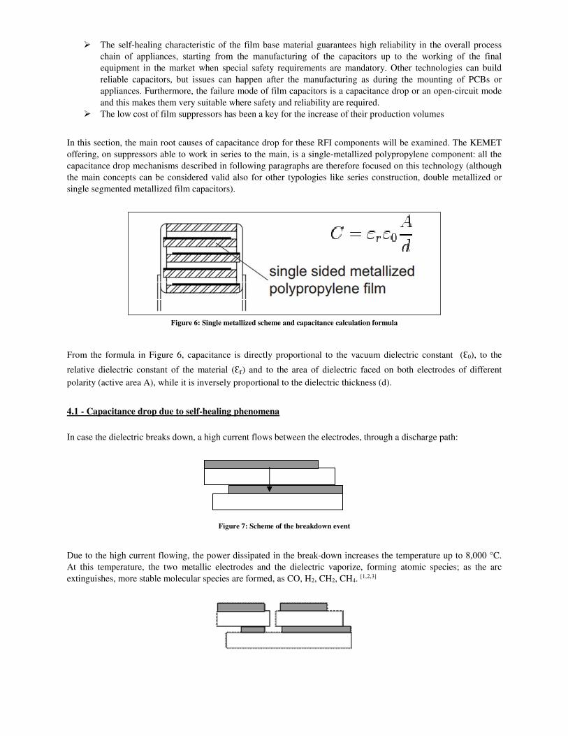
In this section, the main root causes of capacitance drop for these RFI components will be examined. The KEMET
offering, on suppressors able to work in series to the main, is a single-metallized polypropylene component: all the
capacitance drop mechanisms described in following paragraphs are therefore focused on this technology (although
the main concepts can be considered valid also for other typologies like series construction, double metallized or
single segmented metallized film capacitors).
Figure 6: Single metallized scheme and capacitance calculation formula
From the formula in Figure 6, capacitance is directly proportional to the vacuum dielectric constant (Ɛ0), to the
relative dielectric constant of the material (Ɛr) and to the area of dielectric faced on both electrodes of different
polarity (active area A), while it is inversely proportional to the dielectric thickness (d).
4.1 - Capacitance drop due to self-healing phenomena
In case the dielectric breaks down, a high current flows between the electrodes, through a discharge path:
Figure 7: Scheme of the breakdown event
Due to the high current flowing, the power dissipated in the break-down increases the temperature up to 8,000 °C.
At this temperature, the two metallic electrodes and the dielectric vaporize, forming atomic species; as the arc
extinguishes, more stable molecular species are formed, as CO, H2, CH2, CH4. [1,2,3]
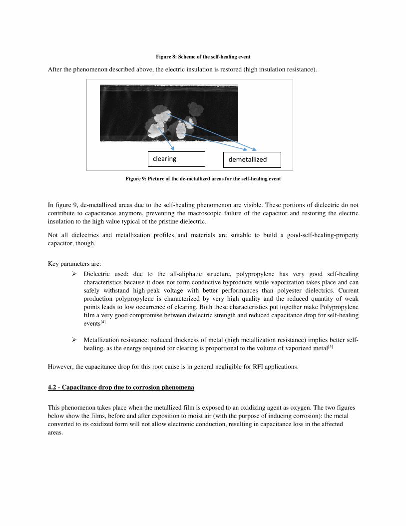
Figure 8: Scheme of the self-healing event
After the phenomenon described above, the electric insulation is restored (high insulation resistance).
Figure 9: Picture of the de-metallized areas for the self-healing event
In figure 9, de-metallized areas due to the self-healing phenomenon are visible. These portions of dielectric do not
contribute to capacitance anymore, preventing the macroscopic failure of the capacitor and restoring the electric
insulation to the high value typical of the pristine dielectric.
Not all dielectrics and metallization profiles and materials are suitable to build a good-self-healing-property
capacitor, though.
Key parameters are:
� Dielectric used: due to the all-aliphatic structure, polypropylene has very good self-healing
characteristics because it does not form conductive byproducts while vaporization takes place and can
safely withstand high-peak voltage with better performances than polyester dielectrics. Current
production polypropylene is characterized by very high quality and the reduced quantity of weak
points leads to low occurrence of clearing. Both these characteristics put together make Polypropylene
film a very good compromise between dielectric strength and reduced capacitance drop for self-healing
events[4]
� Metallization resistance: reduced thickness of metal (high metallization resistance) implies better self-
healing, as the energy required for clearing is proportional to the volume of vaporized metal[5]
However, the capacitance drop for this root cause is in general negligible for RFI applications.
4.2 - Capacitance drop due to corrosion phenomena
This phenomenon takes place when the metallized film is exposed to an oxidizing agent as oxygen. The two figures
below show the films, before and after exposition to moist air (with the purpose of inducing corrosion): the metal
converted to its oxidized form will not allow electronic conduction, resulting in capacitance loss in the affected
areas.
demetallized clearing
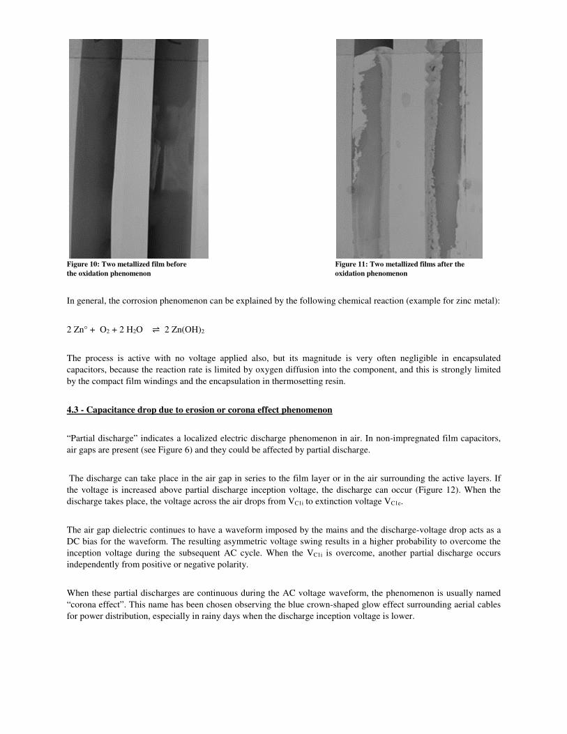
Figure 10: Two metallized film before Figure 11: Two metallized films after the
the oxidation phenomenon oxidation phenomenon
In general, the corrosion phenomenon can be explained by the following chemical reaction (example for zinc metal):
2 Zn° + O2 + 2 H2O ⇌ 2 Zn(OH)2
The process is active with no voltage applied also, but its magnitude is very often negligible in encapsulated
capacitors, because the reaction rate is limited by oxygen diffusion into the component, and this is strongly limited
by the compact film windings and the encapsulation in thermosetting resin.
4.3 - Capacitance drop due to erosion or corona effect phenomenon
“Partial discharge” indicates a localized electric discharge phenomenon in air. In non-impregnated film capacitors,
air gaps are present (see Figure 6) and they could be affected by partial discharge.
The discharge can take place in the air gap in series to the film layer or in the air surrounding the active layers. If
the voltage is increased above partial discharge inception voltage, the discharge can occur (Figure 12). When the
discharge takes place, the voltage across the air drops from VC1i to extinction voltage VC1e.
The air gap dielectric continues to have a waveform imposed by the mains and the discharge-voltage drop acts as a
DC bias for the waveform. The resulting asymmetric voltage swing results in a higher probability to overcome the
inception voltage during the subsequent AC cycle. When the VC1i is overcome, another partial discharge occurs
independently from positive or negative polarity.
When these partial discharges are continuous during the AC voltage waveform, the phenomenon is usually named
“corona effect”. This name has been chosen observing the blue crown-shaped glow effect surrounding aerial cables
for power distribution, especially in rainy days when the discharge inception voltage is lower.
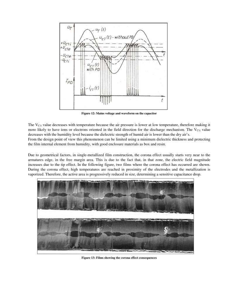
Figure 12: Mains voltage and waveform on the capacitor
The VC1i value decreases with temperature because the air pressure is lower at low temperature, therefore making it
more likely to have ions or electrons oriented in the field direction for the discharge mechanism. The VC1i value
decreases with the humidity level because the dielectric strength of humid air is lower than the dry air’s.
From the design point of view this phenomenon can be limited using a minimum dielectric thickness and protecting
the film internal element from humidity, with good enclosure materials as box and resin.
Due to geometrical factors, in single-metallized film construction, the corona effect usually starts very near to the
armatures edge, in the free margin area. This is due to the fact that, in that zone, the electric field magnitude
increases due to the tip effect. In the following figure, two films where the corona effect has occurred are shown.
During the corona effect, high temperatures are reached in proximity of the electrodes and the metallization is
vaporized. Therefore, the active area is progressively reduced in size, determining a sensitive capacitance drop.
Figure 13: Films showing the corona effect consequences
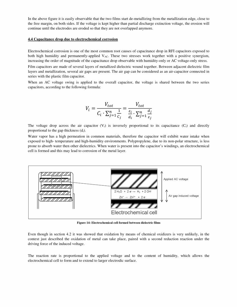
In the above figure it is easily observable that the two films start de-metallizing from the metallization edge, close to
the free margin, on both sides. If the voltage is kept higher than partial discharge extinction voltage, the erosion will
continue until the electrodes are eroded so that they are not overlapped anymore.
4.4 Capacitance drop due to electrochemical corrosion
Electrochemical corrosion is one of the most common root causes of capacitance drop in RFI capacitors exposed to
both high humidity and permanently-applied VAC. These two stresses work together with a positive synergism,
increasing the order of magnitude of the capacitance drop observable with humidity-only or AC voltage-only stress.
Film capacitors are made of several layers of metallized dielectric wound together. Between adjacent dielectric film
layers and metallization, several air gaps are present. The air gap can be considered as an air-capacitor connected in
series with the plastic film capacitor.
When an AC voltage swing is applied to the overall capacitor, the voltage is shared between the two series
capacitors, according to the following formula:
�� � ������ ∙ ∑
�� ��
� ��������∙ ∑ ��
�� ��
The voltage drop across the air capacitor (Vi) is inversely proportional to its capacitance (Ci) and directly
proportional to the gap thickness (di).
Water vapor has a high permeation in common materials, therefore the capacitor will exhibit water intake when
exposed to high- temperature and high-humidity environments. Polypropylene, due to its non-polar structure, is less
prone to absorb water then other dielectrics. When water is present into the capacitor’s windings, an electrochemical
cell is formed and this may lead to corrosion of the metal layer.
Figure 14: Electrochemical cell formed between dielectric films
Even though in section 4.2 it was showed that oxidation by means of chemical oxidizers is very unlikely, in the
context just described the oxidation of metal can take place, paired with a second reduction reaction under the
driving force of the induced voltage.
The reaction rate is proportional to the applied voltage and to the content of humidity, which allows the
electrochemical cell to form and to extend to larger electrodic surface.
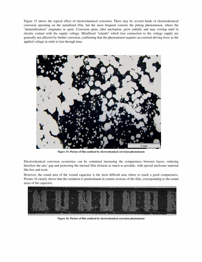
Figure 15 shows the typical effect of electrochemical corrosion. There may be several kinds of electrochemical
corrosion operating on the metallized film, but the most frequent consists the pitting phenomenon, where the
“demetallization” originates in spots. Corrosion spots, after nucleation, grow radially and may overlap until in
electric contact with the supply voltage. Metallized “islands” which lose connection to the voltage supply are
generally not affected by further corrosion, confirming that the phenomenon requires an external driving force as the
applied voltage in order to last through time.
Figure 15: Picture of film oxidized by electrochemical corrosion phenomenon
Electrochemical corrosion occurrence can be contained increasing the compactness between layers, reducing
therefore the airs’ gap and protecting the internal film element as much as possible, with special enclosure material
like box and resin.
However, the round area of the wound capacitor is the most difficult area where to reach a good compactness.
Picture 16 clearly shows that the oxidation is predominant in certain sections of the film, corresponding to the round
areas of the capacitor.
Figure 16: Picture of film oxidized by electrochemical corrosion phenomenon
5 - PERFORMANCES OF SUPPRESSOR CAPACITORS AT DIFFERENT HUMIDITY-STRESS LEVEL
KEMET has recently released a product series in line with the requirements of high capacitance stability in harsh
environment conditions like 85°C/85% R.H. with AC voltage applied. In the design of this product series, the full
list of root causes illustrated in section 4 have been considered.
As already indicated, KEMET’s choice is a single metallized polypropylene capacitor (named “F862” series), not
impregnated. This design choice implies the following advantages:
� This simple construction (single metallized) contains the component’s cost and, therefore, does not limit its
use to applications in which the humidity level is very severe, but also in all applications where a high level
of stability is required
� Using single-metallized polypropylene implies having very low dissipation factor values, so that this
product can be placed in the first filtering stage also, where the harmonics at high frequencies could induce
a high self-heating (e.g. in capacitors made with polyester film, whose dissipation factor values are higher)
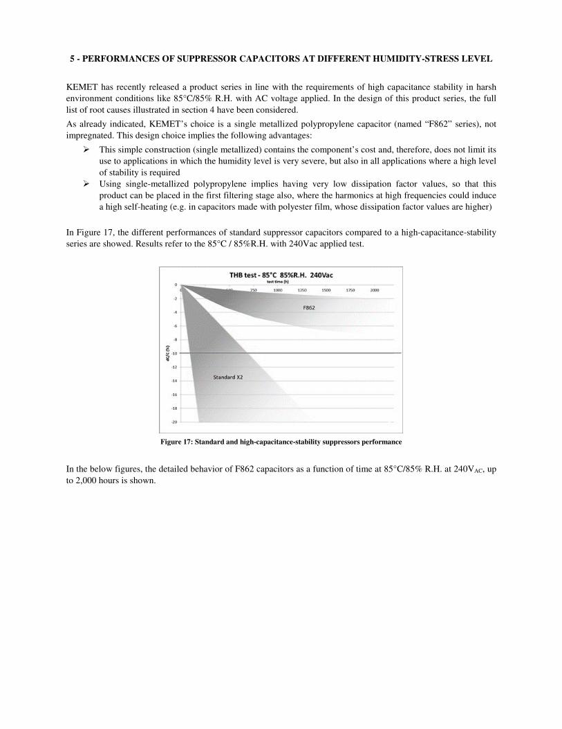
In Figure 17, the different performances of standard suppressor capacitors compared to a high-capacitance-stability
series are showed. Results refer to the 85°C / 85%R.H. with 240Vac applied test.
Figure 17: Standard and high-capacitance-stability suppressors performance
In the below figures, the detailed behavior of F862 capacitors as a function of time at 85°C/85% R.H. at 240VAC, up
to 2,000 hours is shown.

Figure 18 and 19: F862 series performance in 85°C/85% R.H./240 VAC test.
In the above mentioned test, the performance of the capacitors shows usually three different behaviors through time:
� Up to 250-350 hours, the capacitance drop is negligible since the humidity has not penetrated inside the
film element yet
� From 250-350 to roughly 600 hours, the capacitance drop slope becomes steeper, due to electrochemical
corrosion being activated
� Stabilization of the capacitance is then visible, with a very good performances up to 2,000 hours
In the below figures, F862 series behavior in other harsh-environment condition are shown:
� 40°C/93% R.H. with 240 VAC applied
� 60°C/85% R.H. with 240 VAC applied
� 85°C/85% R.H. with 220 VAC applied
� 85°C/85% R.H. with 264 VAC applied
� 85°C/85% R.H. with 310 VAC applied
Figure 20: F862 series performance in 40°C/93% Figure 21: F862 series performance in 60°C/85%
R.H./240 VAC test R.H./240 VAC test
For tests performed in the conditions 40°C/93%r.h. and 60°C/85%r.h., only partial data are available, up
to 500h. At the moment of this writing the tests are still running and the model will be updated when
further results will be available
High
Avg
Low
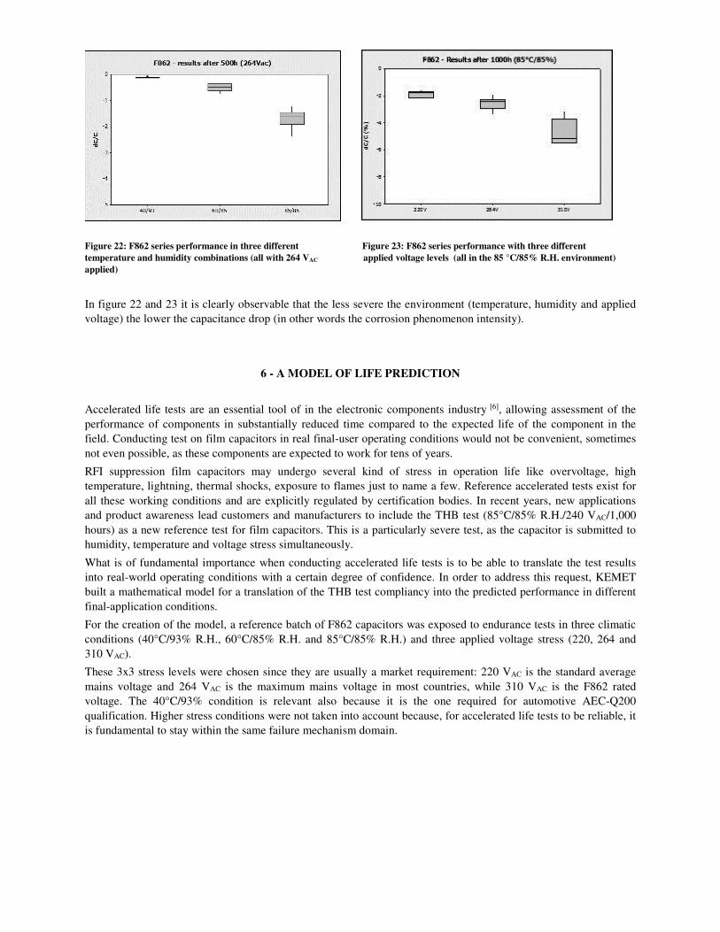
Figure 22: F862 series performance in three different Figure 23: F862 series performance with three different temperature and humidity combinations (all with 264 VAC applied voltage levels (all in the 85 °C/85% R.H. environment) applied)
In figure 22 and 23 it is clearly observable that the less severe the environment (temperature, humidity and applied
voltage) the lower the capacitance drop (in other words the corrosion phenomenon intensity).
6 - A MODEL OF LIFE PREDICTION
Accelerated life tests are an essential tool of in the electronic components industry [6], allowing assessment of the
performance of components in substantially reduced time compared to the expected life of the component in the
field. Conducting test on film capacitors in real final-user operating conditions would not be convenient, sometimes
not even possible, as these components are expected to work for tens of years.
RFI suppression film capacitors may undergo several kind of stress in operation life like overvoltage, high
temperature, lightning, thermal shocks, exposure to flames just to name a few. Reference accelerated tests exist for
all these working conditions and are explicitly regulated by certification bodies. In recent years, new applications
and product awareness lead customers and manufacturers to include the THB test (85°C/85% R.H./240 VAC/1,000
hours) as a new reference test for film capacitors. This is a particularly severe test, as the capacitor is submitted to
humidity, temperature and voltage stress simultaneously.
What is of fundamental importance when conducting accelerated life tests is to be able to translate the test results
into real-world operating conditions with a certain degree of confidence. In order to address this request, KEMET
built a mathematical model for a translation of the THB test compliancy into the predicted performance in different
final-application conditions.
For the creation of the model, a reference batch of F862 capacitors was exposed to endurance tests in three climatic
conditions (40°C/93% R.H., 60°C/85% R.H. and 85°C/85% R.H.) and three applied voltage stress (220, 264 and
310 VAC).
These 3x3 stress levels were chosen since they are usually a market requirement: 220 VAC is the standard average
mains voltage and 264 VAC is the maximum mains voltage in most countries, while 310 VAC is the F862 rated
voltage. The 40°C/93% condition is relevant also because it is the one required for automotive AEC-Q200
qualification. Higher stress conditions were not taken into account because, for accelerated life tests to be reliable, it
is fundamental to stay within the same failure mechanism domain.
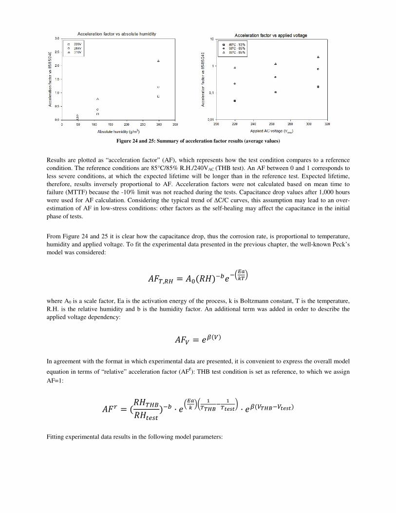
Figure 24 and 25: Summary of acceleration factor results (average values)
Results are plotted as “acceleration factor” (AF), which represents how the test condition compares to a reference
condition. The reference conditions are 85°C/85% R.H./240VAC (THB test). An AF between 0 and 1 corresponds to
less severe conditions, at which the expected lifetime will be longer than in the reference test. Expected lifetime,
therefore, results inversely proportional to AF. Acceleration factors were not calculated based on mean time to
failure (MTTF) because the -10% limit was not reached during the tests. Capacitance drop values after 1,000 hours
were used for AF calculation. Considering the typical trend of ∆C/C curves, this assumption may lead to an over-
estimation of AF in low-stress conditions: other factors as the self-healing may affect the capacitance in the initial
phase of tests.
From Figure 24 and 25 it is clear how the capacitance drop, thus the corrosion rate, is proportional to temperature,
humidity and applied voltage. To fit the experimental data presented in the previous chapter, the well-known Peck’s
model was considered:
���,�� � ��(��)�� �!"#$%&
where A0 is a scale factor, Ea is the activation energy of the process, k is Boltzmann constant, T is the temperature,
R.H. is the relative humidity and b is the humidity factor. An additional term was added in order to describe the
applied voltage dependency:
��' � ((')
In agreement with the format in which experimental data are presented, it is convenient to express the overall model
equation in terms of “relative” acceleration factor (AFr): THB test condition is set as reference, to which we assign
AF=1:
��) � (����*���+,�
)�� · !"#$ &. /
%%01�/
%23425 · (('%01�'2342)
Fitting experimental data results in the following model parameters:
Ea = 0.6 eV
b = -2.66
β = -0.011
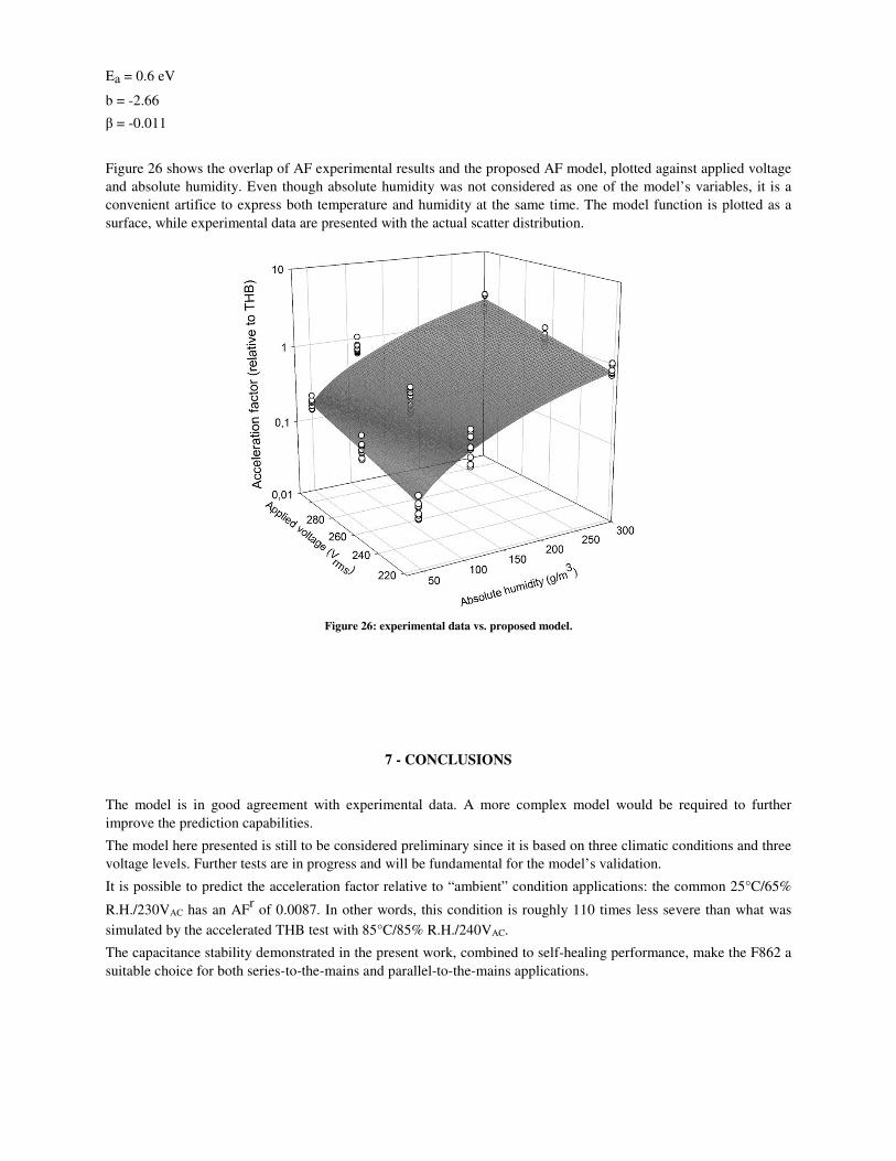
Figure 26 shows the overlap of AF experimental results and the proposed AF model, plotted against applied voltage
and absolute humidity. Even though absolute humidity was not considered as one of the model’s variables, it is a
convenient artifice to express both temperature and humidity at the same time. The model function is plotted as a
surface, while experimental data are presented with the actual scatter distribution.
Figure 26: experimental data vs. proposed model.
7 - CONCLUSIONS
The model is in good agreement with experimental data. A more complex model would be required to further
improve the prediction capabilities.
The model here presented is still to be considered preliminary since it is based on three climatic conditions and three
voltage levels. Further tests are in progress and will be fundamental for the model’s validation.
It is possible to predict the acceleration factor relative to “ambient” condition applications: the common 25°C/65%
R.H./230VAC has an AFr of 0.0087. In other words, this condition is roughly 110 times less severe than what was
simulated by the accelerated THB test with 85°C/85% R.H./240VAC.
The capacitance stability demonstrated in the present work, combined to self-healing performance, make the F862 a
suitable choice for both series-to-the-mains and parallel-to-the-mains applications.

REFERENCES
[1] J.H. Tortai, et al., “Diagnostic of the self-healing of metallized polypropylene film by modeling of the
broadening emission lines of aluminum emitted by plasma discharge”, Journal of Applied Physics 97, 053304, 2005
[2] J. Kammermaier, et al., “Modeling of plasma-induced self-healing in organic dielectrics”, Siemens AG
Corporate Research and Development, 8520 Erlangen, 7 april 1989
[3] C. W. Reed, S. W. Cichanowski “The Fundamentals of Aging in HV Polymer-film Capacitors”, IEEE
Transactions on Dielectrics and Electrical Insulation Vol. 1 No. 5, october 1994
[4] X. Dai, et al., “Influence Factors for the Self-healing of Metallized Polypropylene Capacitors”, 2000 Conference
on Electrical Insulation and Dielectric Phenomena
[5] J.H. Tortai, A. Denat, N. Bonifaci “Self-healing of capacitors with metallized film technology: experimental
observations and theoretical model”, Journal of Electrostatics 53 (2001) 159–169
[6] Evangelista Boni et al., “SMD naked film capacitor technologies for severe environments and circuit functions”,
2011 CARTS Proceedings, March 2011, Jacksonville, FL, USA