Embed Size (px)
Citation preview
RF PULSE COMPRESSION STABILIZATIONAT THE CTF3 CLIC TEST FACILITY
A. Dubrovskiy, F. Tecker, CERN, Geneva, Switzerland
Abstract
In the CTF3 accelerator, the RF produced by each often 3 GHz klystrons goes through waveguides, RF pulsecompressors and splitters. The RF phase and power trans-formation of these devices depend on their temperature.The quantitative effect of the room temperature variationon the RF was measured. It is the major source of unde-sired changes during the CTF3 operation. An RF phase-loop and a compressor temperature stabilization are devel-oped to suppress the phase fluctuation and the power profilechange due to the temperature variation. The implementa-tion is transparent for operators, it does not limit anyhowthe flexibility of RF manipulations. Expected and mea-sured suppression characteristics will be given.
INTRODUCTION
In the context of the feasibility demonstration of theCLIC linear collider [1], the CLIC Test Facility CTF3 [2]is to demonstrate in particular the generation of the highcurrent, so called “drive beam” of CLIC. The drive beamin CTF3 is accelerated in 3 GHz S-band travelling-waveaccelerating structures. In order to reach the required RFpower of over 30 MW, the RF pulse from the klystrons isfed into an RF pulse compression system that provides apower gain of about two in klystron peak power [3].
The pulse compression cavities (so called LIPS- andBOC cavities) need to be precisely tuned, and their reso-nant frequencies must be stabilized to ±1.5 kHz to achievethe required ±1% amplitude and ±5◦ phase stability. Thiscorresponds to ±0.03◦C of maximum permitted tempera-ture variation. Each compressor cavity is connected to anindividual cooling circuit, where the mean water tempera-ture is stabilized to this level.
Nevertheless, an important change of the pulse com-pression was observed during operation when the ambi-ent room temperature in the klystron gallery changes orwhen the power level in the cavity was changing (Fig. 1).Since these variations require frequent time-consuming re-optimization of the RF pulse compression during CTF3operation, the system described in the following was con-ceived and implemented to stabilize the RF pulse compres-sion.
MODEL
In the normal operation the compressed RF pulse mustbe high power with a low phase deviation along 1.4μs.The klystron low-level RF phase waveform programming
6500 7000 7500 8000
32
33
34
35
36
37
ns
MW
C
22.4
22.7
23.0
23.3
23.5
23.8
Figure 1: Power variation along the pulse at different am-bient room temperature
6600 6800 7000 7200 7400 7600 7800 8000
2
1
0
1
2
3
ns
deg
C
22.4
22.7
23.0
23.3
23.5
23.8
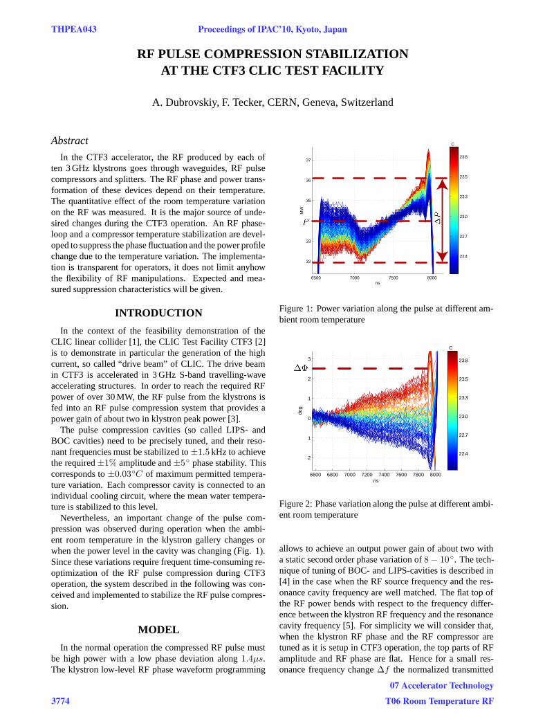
Figure 2: Phase variation along the pulse at different ambi-ent room temperature
allows to achieve an output power gain of about two witha static second order phase variation of 8 − 10◦. The tech-nique of tuning of BOC- and LIPS-cavities is described in[4] in the case when the RF source frequency and the res-onance cavity frequency are well matched. The flat top ofthe RF power bends with respect to the frequency differ-ence between the klystron RF frequency and the resonancecavity frequency [5]. For simplicity we will consider that,when the klystron RF phase and the RF compressor aretuned as it is setup in CTF3 operation, the top parts of RFamplitude and RF phase are flat. Hence for a small res-onance frequency change Δf the normalized transmitted
THPEA043 Proceedings of IPAC’10, Kyoto, Japan
3774
07 Accelerator Technology
T06 Room Temperature RF

wave at the flat top can be written as:
EL = A(Δf)ei(ω+2πΔf)t+iφ(Δf) + ei(ωt), (1)
where ω = 2πfrf , φ(Δf) is a the phase shift differenceafter the actual filling time, and A(Δf) is the amplitude ofthe emitted wave, mainly changed due to the stored energydifference. The last satisfies the following condition:
|A| < 2β
β + 1, (2)
where β is the coupling coefficient between the waveguideand the cavity. The cavity resonance frequency is very sen-sitive to the size of the cavity. The frequency shift inducedby the temperature change is given by:
Δf = frf −frf
1 + λLΔT. (3)
The linear thermal expansion can be taken for the coppermaterial λL = 17 ∗ 10−6 1
◦C . For small temperature fluc-tuations the frequency shift Δf is linearly proportional toΔT . Hence the temperature change of 0.196◦C shifts theresonance frequency by 10 kHz. Using the rough approx-imation of the transmitted wave (1) and assuming parame-ters for the CTF3 case, the amplitude stability ΔP
P is pro-portional to the square of the frequency difference and thephase variation ΔΦ is linearly proportional to Δf , thus:
ΔP
P∼ ΔT 2, ΔΦ ∼ ΔT. (4)
The last relations (4) agree with the observations. Thepower variation along the pulse with respect to the ambi-ent room temperature variation is shown in Fig. 1, wherethe gradient of power slope ΔP
P satisfies the condition (4).Figure 2 illustrates the phase variation ΔΦ along the pulsewith respect to the ambient room temperature. The staticsecond order phase variation of 4◦ was subtracted fromthe phase measurements and they were aligned with a fixpoint 0◦ at a certain position. The measurements were doneover several hours. The observed fluctuation of the ambi-ent room temperature of 2◦C increases the power variationfrom 2% to 10% and the additional phase variation by 4◦.The cavity temperature varies along the day with to the am-bient temperature. This strong temperature influence is notacceptable for the CTF3 machine operation.
IMPLEMENTATION OF STABILIZATION
Each RF compressor is equipped with a water coolingsystem. The incoming Tin and outcoming Tout temper-atures are measured. At a constant water flow rate, awater temperature feedback keeps the mean temperature(Tin + Tout)/2 constant. All measurements above (Fig.1 and 2) were taken with the feedback switched on. Thispoints out that the current approach applied in CTF3 is in-sufficient for the RF stabilization. Below we will describethe new approach.
A few assumptions should be made. The first assump-tion is that the water flow is turbulent enough, that at anyposition in the cooling tube the averaged temperature over aperiod of a second remains the same if the dissipation staysconstant. The second, the temperature dissipation in theRF compressor is homogeneous, much faster than the am-bient room temperature change ( 1 hour) and slower thanthe period between RF pulses ( 0.1 sec). Hence a generictemperature of the compressor TBOC can be assumed. Thegeneric temperature is not necessarily the temperature of ahardware part, it represents the resonance frequency.
The generic temperature depends on the air temperatureTair , the cooling water temperature and the dissipated en-ergy Udis in the cavity (Fig. 3). Using thermodynamicslaws it can be expressed as
TBOCin = Tin − k1(Tin − Tair ),TBOCout = TBOCin − k2(TBOCin − TBOC ),
Tout = TBOCout − k1(TBOCout − Tair ),∂TBOC
∂t = k3(TBOC − Tair ) + k4Udis+k5(TBOCout − TBOCin),
(5)
where TBOCin and TBOCout - incoming and outcomingBOC water temperature, Tin and Tout - measured incom-ing and outcoming water temperature, k1 is the couplingcoefficient between the water tube and the surrounding air,k3 is the coupling coefficient between the RF compressorand the surrounding air, k2 and k5 - the coupling coeffi-cients between the RF compressor and the water tube. Inthis model the temperature loss in the lead-in tube is con-sidered, what’s why the temperatures TBOCin and Tin aredifferent, as well as TBOCout and Tout . Simulations with2◦ room temperature variation showed the BOC tempera-ture variation of half a degree, where the standard water andcopper coupling coefficients were used. Since the generictemperature changes slowly we can take ∂TBOC
∂t � 1. Thus,
Figure 3: Scheme of actors affecting the RF compressortemperature change. Blue arrows are incoming and out-coming water cooling pipes; red arrows are klystron andcompressed RF waveguides; the cloud is the surroundingair.
Proceedings of IPAC’10, Kyoto, Japan THPEA043
07 Accelerator Technology
T06 Room Temperature RF 3775

using equations (4) and (5) the RF phase variation along thepulse should satisfy the following equation:
ΔΦ = a0 + a1Tin + a2Tout + a3Tair + a4Udis , (6)
where a0,a1, a2, a3 and a4 are some constants and the dis-sipated energy is linearly proportional to the missing en-ergy, which is measured using power-meters before and af-ter the compressor. The unknown constants can be foundfrom measured data by fitting the last equation over a pe-riod with significant temperature and dissipated power vari-ations.
The water mean temperature control is the actuator forthe stabilization control system. In order to stabilize com-pressed RF phase and amplitude, one has to keep the fol-lowing condition:
a1ΔTin + a2ΔTout + a3ΔTair + a4ΔUdis = 0. (7)
So an adaptive discrete feedback system using second or-der filtering has been applied. This solution prevents unsta-ble interactions with a lower level feedback, which keepsthe mean water temperature constant. Being independentof the RF wave shapes, the controller is absolutely trans-parent for operators. Numerical analysis showed that thisapproach will significantly improve the RF stability issueclose to the requirements. The stabilization system will beimplemented in coming months.
PHASE STABILIZATION
RF measurements at the input of the accelerating struc-ture showed that the phase waveform offset changes intime. One of the sources is the phase shift φ(Δf) in theRF compressor related to the cavity resonance frequencychange. Another source is the temperature change of longwaveguides and phase shifters. But also there exist un-known sources changing the phase offset. In total phaseoffset variations of over 10 degrees were observed along aday.
In addition to the stabilization of the RF pulse compres-sion system, a low-level RF phase loop is used (Fig. 4).The RF phase at the input of the accelerating structure ismeasured with respect to the reference of the klystron low-level RF. The phase compensator allows to set the phasereference point to zero. The phase shifter, which is installedbetween the low-level RF reference and the klystron, al-lows to control the phase offset. In order to compensatephase offset fluctuations, a slow pulse-to-pulse feedbacksystem with first order filtering has been applied. An idealfeedback method would be able to reduce the phase vari-ation down to ±0.3◦. For the stabilization system in thedescribed configuration the expected residual phase varia-tion is ± 1◦. The measured variation was around ±1.1◦
and the standard deviation was between 0.4◦ and 0.7◦, itdepends on the feedback configuration for the individualcircuit. The smaller standard deviation is measured for themore frequent phase adjustment, the lower limit is given bythe highest machine control frequency of 0.8 Hz.
K
Phase shifter
RF compressor
3dB
ACC ACC
Phase compensator
Acquisitionphase
Klystron
Low level reference RF
Phase programmer
Figure 4: Phase loop layout. Bold lines are high powerRF waveguides, thin lines - low level RF signals, ACC -accelerating structures.
CONCLUSION
The effect of the daily temperature variation on the high-power RF compressor has the major impact on the RFstability in the CTF3 accelerator. An improved approachto stabilize the RF compression has been described. Theanalysis showed that the feedback stabilization system cansuppress the RF amplitude and phase fluctuations down to±1.5% and ±6◦, respectively. The phase loop stabilizationsystem has shown the expected ability to reduce the phaseoffset fluctuations down to ±1.1◦. The phase loop feed-back demonstrated rigidity and reliability. The RF pulsestabilization systems should significantly improve the sta-bility of CTF3.
ACKNOWLEDGMENTS
The authors thank to I.V.Syrachev, G.McMonagle,J.Sladen and L.Timeo for fruitful discussions. Also theauthors acknowledge to M.Draper, A.Suwalska, K.Kostro,G.Peon, S.Masrie, A.Radeva, P.Lelong and T.Wiszniowskifor technical assistance.
REFERENCES
[1] Assmann, R. W. et al., “A 3 TeV e+e− Linear Collider Basedon CLIC Technology”, Geneva, 2000, CERN.
[2] Geschonke, G. and Ghigo, A., “CTF3 Design Report”,Geneva, 2002, CERN.
[3] Mourier, J., Bossart, R., Nonglaton, J. M., Syratchev, I. V.,and Tanner, L., “Low Level RF Including a SophisticatedPhase Control System for CTF3”, Geneva, 2004, CERN.
[4] Syrachev, I. V., “RF Pulse Compression for the Future LinearCollider”, in Frontiers of Accelerator Technology, edited byKurokawa, S. I., Month, M., and Turner, S., pages 716–741,Japan, 1996, World Scientific.
[5] Bossart, R., Brown, P., Mourier, J., Syratchev, I. V., andTanner, L., “High-power Microwave Pulse Compression ofKlystrons by Phase-Modulation of High-Q Storage Cavities”,Geneva, 2004, CERN.
THPEA043 Proceedings of IPAC’10, Kyoto, Japan
3776
07 Accelerator Technology
T06 Room Temperature RF