Embed Size (px)
Citation preview

RF Products Evaluation Solution Digital Control Software Guide
AN-896
Revision: 001 1
RF Products Evaluation Solution Digital Control Software Guide
8/14/2015

RF Products Evaluation Solution Digital Control Software Guide
Revision: 001 2
Contents 1. Introduction ................................................................................................................................................ 4
2. Requirements .............................................................................................................................................. 4
3. RF Digital Control Software Overview ...................................................................................................... 5
4. Customer Tools and Resources .................................................................................................................. 5
5. Installation Overview ................................................................................................................................. 6
6. Software Installation Procedure ................................................................................................................. 6
7. RF Digital Control Board ......................................................................................................................... 11
7.1. RF Digital Control Board Information .............................................................................................. 11
8. Cable Connection ..................................................................................................................................... 11
8.1. RF Digital Control Board .................................................................................................................. 11
8.2. F1950EVB ......................................................................................................................................... 13
8.2.1. Serial Control Mode ................................................................................................................... 13
8.2.2. Parallel Control Mode ................................................................................................................ 14
8.3. F1951EVB ......................................................................................................................................... 15
8.3.1. Serial Control Mode ................................................................................................................... 15
8.4. F1953EVB ......................................................................................................................................... 16
8.4.1. Serial Control Mode ................................................................................................................... 16
8.4.2. Parallel Control Mode ................................................................................................................ 17
8.5. F1956EVB ......................................................................................................................................... 18
8.5.1. Serial Control Mode ................................................................................................................... 18
8.5.2. Parallel Control Mode ................................................................................................................ 19
8.6. F1912EVB ......................................................................................................................................... 20
8.6.1. Serial Control Mode ................................................................................................................... 20
8.6.2. Parallel Control Mode ................................................................................................................ 21
8.7. F1975EVB ......................................................................................................................................... 22
8.7.1. Serial Mode ................................................................................................................................ 22
8.7.2. Parallel Mode .............................................................................................................................. 23
8.8. F1977EVB ......................................................................................................................................... 24
8.8.1. Serial Mode ................................................................................................................................ 24
8.8.2. Parallel Control Mode ................................................................................................................ 25
8.9. F1200EVB ......................................................................................................................................... 26
8.9.1. Serial Mode ................................................................................................................................ 26
8.9.2. Parallel Mode .............................................................................................................................. 27
8.10. F1240EVB ...................................................................................................................................... 28
8.10.1. Serial Mode ............................................................................................................................. 28
8.10.2. Parallel Mode .......................................................................................................................... 29
RF Products Evaluation Solution Digital Control Software Guide
Revision: 001 3
8.11. F1241EVB ...................................................................................................................................... 30
8.11.1. Parallel Mode .......................................................................................................................... 30
8.12. F0480EVB ...................................................................................................................................... 32
8.12.1. Serial Mode ............................................................................................................................. 32
8.13. Device Configuration ..................................................................................................................... 33
9. Software Application ................................................................................................................................ 34
9.1. Software Installation ........................................................................................................................ 34
9.2. Software Interface ............................................................................................................................ 34
9.2.1. Pin Configuration ....................................................................................................................... 34
9.2.2. Device ......................................................................................................................................... 34
9.2.3. Device Mode .............................................................................................................................. 34
9.2.4. Attenuation Setting ..................................................................................................................... 34
9.2.5. Status .......................................................................................................................................... 35
9.2.6. Stop ............................................................................................................................................. 35
9.2.7. Address ....................................................................................................................................... 35
9.2.8. Channel B ................................................................................................................................... 35
9.3. Parallel Control Option ...................................................................................................................... 35
9.4. EEPROG ............................................................................................................................................ 35
10. Test Environment .................................................................................................................................. 38
11. Supported Devices ................................................................................................................................. 38

RF Products Evaluation Solution Digital Control Software Guide
Revision: 001 4
1. Introduction
IDT offers a wide range of high performance RF products, many of which can be controlled with serial and/or parallel interfaces.
To aid its customers in testing these devices, IDT has developed a Product Evaluation Solution (EVS). IDT’s EVS kit consists of:
A standard Product Evaluation Kit, EVKIT (the product mounted on an evaluation board)
The RF Digital Control Board
All necessary cabling
The RF Digital Control Software downloaded from IDT’s website
The purpose of this application note is to assist customers to properly set-up the EVS hardware and software to control the Product on an evaluation board or EVKIT.
2. Requirements
Customer-supplied hardware:
Computer or laptop:
Must run the Microsoft Windows™ Operating Systems.
Customer must use powered USB port on the computer or laptop to the RF Digital Control Board.
Power supply:
Customer must provide a separate regulated 3 to 5 V input to the Product EVKIT Vdd connection.
IDT supplied hardware:
RF Digital Control Board (USB-based)
Micro-B to USB cable (similar to the USB cable used for cell phones)
Ribbon Cable (connects RF Digital Control Board to Product EVKIT)
IDT’s Product EVKIT
IDT supplied software:
RF Digital Control Software downloaded from www.idt.com website.

RF Products Evaluation Solution Digital Control Software Guide
Revision: 001 5
Figure 1 - EVS hardware configuration
3. RF Digital Control Software Overview
The RF Digital Control Software is a complied LabVIEW application that controls IDT's Product EVKIT using the RF Digital Control Board. The RF Digital Control Board utilizes FTDI’s USB to serial/parallel converter chip, which has been assembled by AdaFruit. The RF Digital Control Software does not require users to have LabVIEW software installed. The installation application, will install all the drivers and runtime engines needed.
4. Customer Tools and Resources
IDT provides customers the following tools and support of the EVS solution
This Application Note
EVS Configuration & Installation Video available at: www.idt.com.
RF Digital Control Software available at: www.idt.com.
RF Product Datasheets provide detailed information on the EVKIT. Available at: www.idt.com.

RF Products Evaluation Solution Digital Control Software Guide
Revision: 001 6
5. Installation Overview
The following installation procedure provides a quick view of the overall installation process. Please visit each section of this application note for a detailed description of each installation step.
1) Obtain the EVS hardware solution for the specific product you plan on evaluating from your IDT Sales
Representative.
i) NOTE: Always follow proper ESD handling procedures when handling electronic components to
avoid damage.
2) Download the RF Digital Control Software from www.idt.com .
3) Follow the Software Installation procedure in this Application Note or video.
4) Using your own cables and regulated power supply, make the proper connections to Vdd (or Vcc) and ground on the
EVKIT for the product you are evaluating.
i) NOTE: Check the Product Datasheet for the correct Vdd supply voltage range before applying Vdd.
Datasheets can be found at www.idt.com
5) Connect the RF Digital Control Board to a powered USB port on your laptop using the USB cable provided.
6) Connect the RF Digital Control Board to the Product EVKIT using the cable provided. This Application Note
provides instructions for each Product EVKIT.
7) Launch the RF Digital Control Software on your laptop and select the specific part number for the EVKIT you are
testing.
8) Using your own cables and test equipment, connect the RF signal to the Product EVKIT. Use the RF Digital Control
Software to digitally control the part during your evaluation.
i) NOTE: Do not apply the RF signal to the Product EVKIT until after Vdd and Logic Voltages are
applied to the EVKIT (in that order).
ii) The product may start in an unknown state. Command product to any state upon startup.
9) When your evaluation is complete:
i) Turn off and disconnect the RF signal applied to the EVKIT.
ii) Turn off and disconnect the Logic voltage and Vdd voltage applied to the EVKIT.
6. Software Installation Procedure
After downloading the RF Digital Control Software from www.idt.com the file needs to be uncompressed. Windows should do this automatically. From this folder right-click on the file Setup (Figure 2) then select Run as administrator. The installation wizard will install the LabVIEW runtime engine, the drivers for the RF Digital Control Board, and the user interface to control the products.

RF Products Evaluation Solution Digital Control Software Guide
Revision: 001 7
Figure 2 - Software Installer zip folder
Once the installation wizard starts, you can choose the destination directory (folder) to place the application file. Click next once you have chosen the destination directory.

RF Products Evaluation Solution Digital Control Software Guide
Revision: 001 8
Figure 3 - Directory locations for software installer file folder
The next step is to accept the software license agreement. Please read the license terms and conditions carefully and accept the license agreement. The software will not be installed without accepting the software license agreement.
Figure 4 - License Terms and Conditions

RF Products Evaluation Solution Digital Control Software Guide
Revision: 001 9
Once the installation is complete, a shortcut for the application is automatically stored in the User’s desktop.
Figure 5 - RF Digital Control Software stored in users desktop
After the Digital Software Control application installation is complete, the software will load the necessary drivers for the RF Digital Control Board which utilizes the FTDI chip. The device driver installation wizard will automatically start running. Click the Extract button to continue the installation of FTDI’s device driver.
Figure 6 - FTDI’s device driver installation

RF Products Evaluation Solution Digital Control Software Guide
Revision: 001 10
Please accept the license agreement and click Next to finish the installation of FTDI’s device driver. Once the installation is complete, users will be able to run the RF Digital Control Software Application.
Figure 7 - FTDI’s device driver license agreement

RF Products Evaluation Solution Digital Control Software Guide
Revision: 001 11
7. RF Digital Control Board
7.1. RF Digital Control Board Information
Figure 8 - RF Digital Control Board
The RF Digital Control Board is built by a company called AdaFruit which utilizes FTDI’s FT232H chip. There are 2 headers with 10-pins used for making digital connection. The header uses standard 100 mil spacing between the pins.
Datasheets for IDT’s Product EVKIT and RF Digital Control Board datasheet can be found in the links provided below:
RF Digital Control Board : http://www.ftdichip.com/Support/Documents/DataSheets/ICs/DS_FT232H.pdf
DSA: http://www.idt.com/products/rf-products
8. Cable Connection
Cables are provided to make the connection between the RF Digital Control Board and the Product EVKIT. Please refer to each figure and table below for correct pin connection using the cable.
NOTE: The Product EVKIT may get damaged if proper procedures are not used.
8.1. RF Digital Control Board
The USB to micro-B cable (similar to cell phone USB cables) is connected from the computer to the RF Digital Control Board. Please refer to the pin configuration tables for each product below for correct connection from the RF Digital Control Board to the Product EVKIT.

RF Products Evaluation Solution Digital Control Software Guide
Revision: 001 12
Figure 9 - Top and side views of cable connections of RF Digital Control Board
Figure 9 shows the pin connection on the RF Digital Control Board. The ribbon cable is connector to the right side header (when looking into the USB connector). Make the brown cable align with the 5 V pin and the black cable with pin D7. A single wire is used to make a connection from the C0 pin of the RF Digital Control Board to the VMODE pin of the Product EVKIT.

RF Products Evaluation Solution Digital Control Software Guide
Revision: 001 13
8.2. F1950EVB
8.2.1. Serial Control Mode
Users should connect a supply voltage between 3 V to 5 V to VDD of the F1950EVB (Product EVKIT). Refer to Table 1 and Figure 10 for correct serial pin connection between the RF Digital Control Board and the F1950EVB.
Figure 10 - Serial Mode pin connection for F1950EVB
Table 1 - Serial Mode pin connection for F1950 EVB
RF Digital Control Board
Wire Color F1950EVB Board Pin
RF Digital Control Board
Wire Color F1950EVB Board Pin
C9 5V BROWN
C8 GND RED GND
C7 D0 ORANGE CK
C6 D1 YELLOW DATA
C5 D2 GREEN
C4 D3 BLUE CS/LE
C3 D4 PURPLE
C2 D5 GREY
C1 D6 WHITE
C0 Single Wire VMODE D7 BLACK

RF Products Evaluation Solution Digital Control Software Guide
Revision: 001 14
8.2.2. Parallel Control Mode
For parallel control mode, users need to run the “EEPROG” application to program the CBUS pin of the RF Digital Control Board. The supply voltage for the VDD should be between 3V to 5V. Please refer to Table 2 and Figure 11 for the correct direct/latched parallel pin connection between the RF Digital Control Board and the F1950EVB.
Figure 11 - Parallel mode pin connection for F1950EVB
Table 2 - Parallel Mode pin connection for F1950EVB
RF Digital Control Board
Wire Color F1950EVB Board Pin
RF Digital Control Board
Wire Color F1950EVB Board Pin
C9 5V BROWN
C8 GND RED GND
C7 D0 ORANGE D0
C6 D1 YELLOW D1
C5 D2 GREEN D2
C4 D3 BLUE D3
C3 D4 PURPLE D4
C2 D5 GREY D5
C1 D6 WHITE D6
C0 Single Wire VMODE D7 BLACK CS/LE

RF Products Evaluation Solution Digital Control Software Guide
Revision: 001 15
8.3. F1951EVB
8.3.1. Serial Control Mode
Users should connect a supply voltage between 3V to 5V to VDD of the F1951EVB. Refer to the Table 3 and the Figure 12 for correct serial pin connection between the RF Digital Control Board and the F1951EVB.
Figure 12 - Serial Mode pin connection for F1951EVB
Table 3 - Serial mode pin connection for F1951EVB
RF Digital Control Board
Wire Color F1951EVBB
oard Pin
RF Digital Control Board
Wire Color F1951EVB Board Pin
C9 5V BROWN
C8 GND RED GND
C7 D0 ORANGE CLK
C6 D1 YELLOW SDI
C5 D2 GREEN
C4 D3 BLUE CS/LE
C3 D4 PURPLE
C2 D5 GREY
C1 D6 WHITE
C0 Single Wire RSTb D7 BLACK
RF Products Evaluation Solution Digital Control Software Guide
Revision: 001 16
8.4. F1953EVB
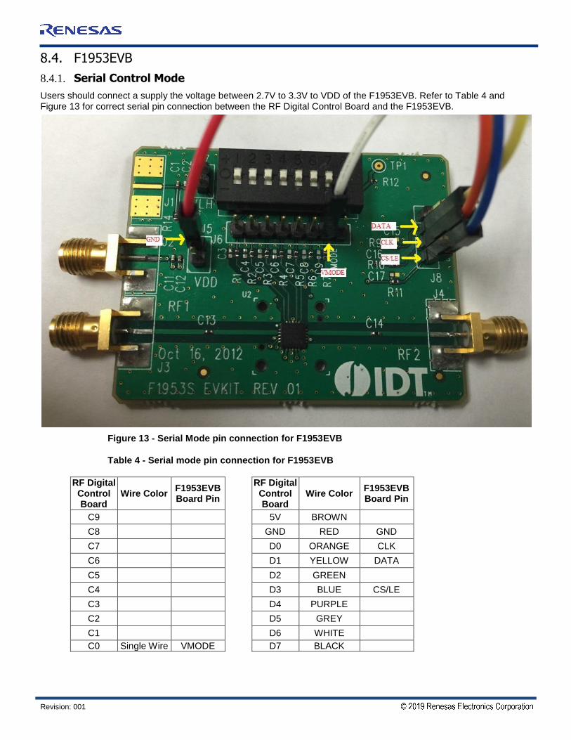
8.4.1. Serial Control Mode
Users should connect a supply the voltage between 2.7V to 3.3V to VDD of the F1953EVB. Refer to Table 4 and Figure 13 for correct serial pin connection between the RF Digital Control Board and the F1953EVB.
Figure 13 - Serial Mode pin connection for F1953EVB
Table 4 - Serial mode pin connection for F1953EVB
RF Digital Control Board
Wire Color F1953EVB Board Pin
RF Digital Control Board
Wire Color F1953EVB Board Pin
C9 5V BROWN
C8 GND RED GND
C7 D0 ORANGE CLK
C6 D1 YELLOW DATA
C5 D2 GREEN
C4 D3 BLUE CS/LE
C3 D4 PURPLE
C2 D5 GREY
C1 D6 WHITE
C0 Single Wire VMODE D7 BLACK
RF Products Evaluation Solution Digital Control Software Guide
Revision: 001 17
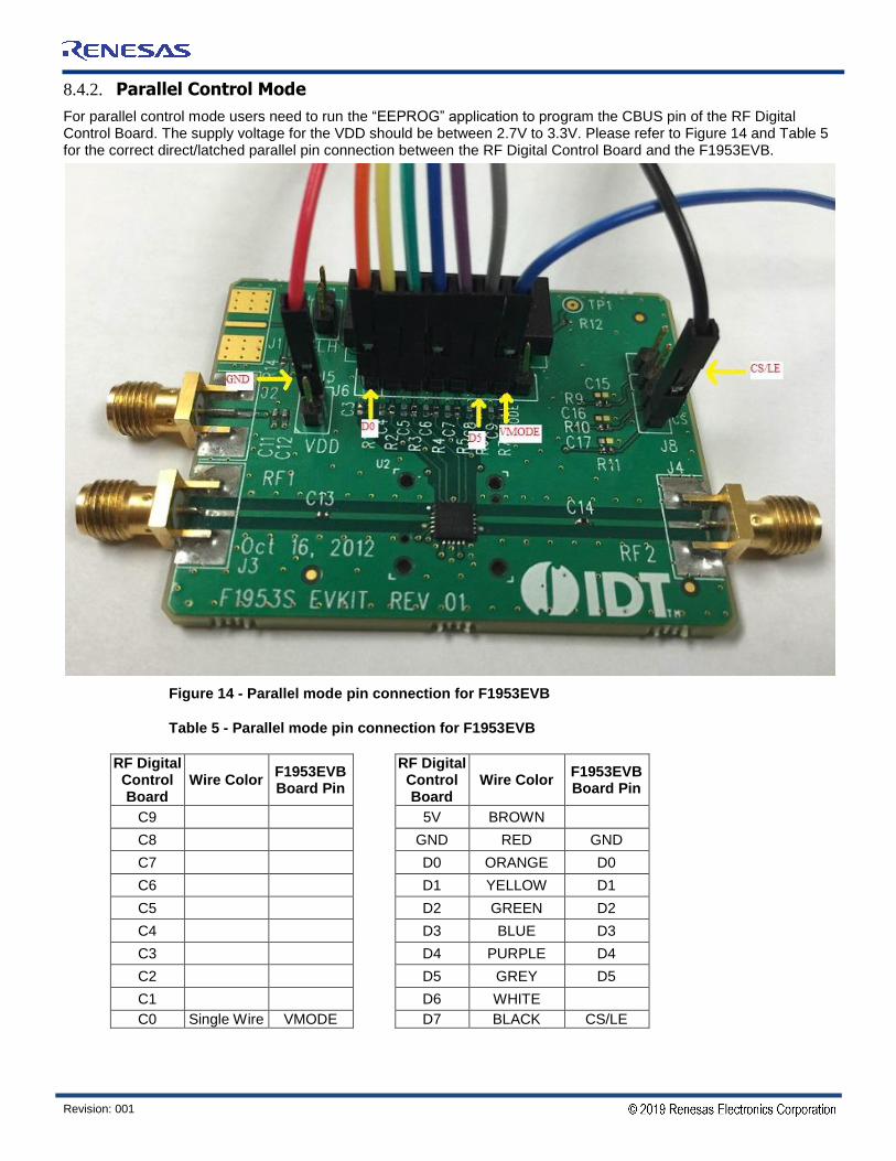
8.4.2. Parallel Control Mode
For parallel control mode users need to run the “EEPROG” application to program the CBUS pin of the RF Digital Control Board. The supply voltage for the VDD should be between 2.7V to 3.3V. Please refer to Figure 14 and Table 5 for the correct direct/latched parallel pin connection between the RF Digital Control Board and the F1953EVB.
Figure 14 - Parallel mode pin connection for F1953EVB
Table 5 - Parallel mode pin connection for F1953EVB
RF Digital Control Board
Wire Color F1953EVB Board Pin
RF Digital Control Board
Wire Color F1953EVB Board Pin
C9 5V BROWN
C8 GND RED GND
C7 D0 ORANGE D0
C6 D1 YELLOW D1
C5 D2 GREEN D2
C4 D3 BLUE D3
C3 D4 PURPLE D4
C2 D5 GREY D5
C1 D6 WHITE
C0 Single Wire VMODE D7 BLACK CS/LE

RF Products Evaluation Solution Digital Control Software Guide
Revision: 001 18
8.5. F1956EVB
8.5.1. Serial Control Mode
Users should connect a supply the voltage between 3.0V to 5.0V to VDD of the F1956EVB. Also supply 5V to VDD (J10 on the F1956EVB) to provide voltage to 10 pin DIP Switches for serial address word control. Refer to Table 6 and Figure 15 for correct serial pin connection between the RF Digital Control Board and the F1956EVB.
Figure 15 - Serial mode pin connection for F1956EVB
Table 6 - Serial mode pin connection for F1956EVB
RF Digital Control Board
Wire Color F1956EVB Board Pin
RF Digital Control Board
Wire Color F1956EVB Board Pin
C9 5V BROWN
C8 GND RED GND
C7 D0 ORANGE CLK
C6 D1 YELLOW DATA
C5 D2 GREEN
C4 D3 BLUE CS/LE
C3 D4 PURPLE
C2 D5 GREY
C1 D6 WHITE
C0 Single Wire VMODE D7 BLACK

RF Products Evaluation Solution Digital Control Software Guide
Revision: 001 19
8.5.2. Parallel Control Mode
For parallel control mode users need to run the “EEPROG” application to program the CBUS pin of the RF Digital Control Board. The supply for the VDD should be between 3.0 V to 5.0 V Refer to Figure 16 and Table 7 for correct direct/latched parallel pin connection between the RF Digital Control Board and the F1956EVB.
Figure 16 - Parallel Mode pin connection for F1956EVB
Table 7 - Parallel Mode pin connection for F1956EVB
RF Digital Control Board Wire Color
F1956EVB Board Pin
RF Digital Control Board Wire Color
F1956EVB Board Pin
C9 5V BROWN
C8 GND RED GND
C7 D0 ORANGE D0
C6 D1 YELLOW D1
C5 D2 GREEN D2
C4 D3 BLUE D3
C3 D4 PURPLE D4
C2 D5 GREY D5
C1 D6 WHITE D6
C0 Single Wire VMODE D7 BLACK CS/LE

RF Products Evaluation Solution Digital Control Software Guide
Revision: 001 20
8.6. F1912EVB
8.6.1. Serial Control Mode
Users should connect a supply voltage between 3.0 V to 5.25 V to VDD of the F1912EVB. Refer to Table 8 and Figure 17 for correct serial pin connection between the RF Digital Control Board and the F1912EVB.
Figure 17 - Serial mode pin connection for F1912EVB
Table 8 - Serial mode pin connection for F1912EVB
RF Digital Control Board Wire Color
F1912EVB Board Pin
RF Digital Control Board Wire Color
F1912EVB Board Pin
C9 5V BROWN
C8 GND RED GND
C7 D0 ORANGE CLK
C6 D1 YELLOW DATA
C5 D2 GREEN
C4 D3 BLUE CS/LE
C3 D4 PURPLE
C2 D5 GREY
C1 D6 WHITE
C0 Single Wire VMODE D7 BLACK

RF Products Evaluation Solution Digital Control Software Guide
Revision: 001 21
8.6.2. Parallel Control Mode
For parallel control mode users need to run the “EEPROG” application to program the CBUS pin of the RF Digital Control Board. The supply voltage for the VDD should be between 3.0 V to 5.25 V. Please refer to Figure 18 and Table 9 for correct direct/latched parallel pin connection between the RF Digital Control Board and theF1912EVB.
Figure 18 - Parallel mode pin connection for F1912EVB
Table 9 - Parallel mode pin connection for F1912EVB
RF Digital Control Board Wire Color
F1912EVB Board Pin
RF Digital Control Board Wire Color
F1912EVB Board Pin
C9 5V BROWN
C8 GND RED GND
C7 D0 ORANGE D0
C6 D1 YELLOW D1
C5 D2 GREEN D2
C4 D3 BLUE D3
C3 D4 PURPLE D4
C2 D5 GREY D5
C1 D6 WHITE
C0 Single Wire VMODE D7 BLACK CS/LE

RF Products Evaluation Solution Digital Control Software Guide
Revision: 001 22
8.7. F1975EVB
8.7.1. Serial Mode
Users should connect a supply the voltage between 3.0V to 5.25V to VDD of the F1975EVB. Refer to Table 10 and Figure 19 for correct serial pin connection between the RF Digital Control Board and the F1975EVB.
Figure 19 - Serial Mode pin connection for F1975EVB
Table 10 - Serial Mode pin connection for F1975EVB
RF Digital Control Board Wire Color
F1975EVB Board Pin
RF Digital Control Board Wire Color
F1975EVB Board Pin
C9 5V BROWN
C8 GND RED GND
C7 D0 ORANGE CLK
C6 D1 YELLOW DATA
C5 D2 GREEN
C4 D3 BLUE CS/LE
C3 D4 PURPLE
C2 D5 GREY
C1 D6 WHITE
C0 Single Wire VMODE D7 BLACK

RF Products Evaluation Solution Digital Control Software Guide
Revision: 001 23
8.7.2. Parallel Mode
For parallel control mode users need to run the “EEPROG” application to program the CBUS pin of the RF Digital Control Board. The supply voltage for the VDD should be between 3.0 V to 5.25 V. Please refer to Figure 20 and Table 11 for correct direct/latched parallel pin connection between the RF Digital Control Board and the F1975EVB.
Figure 20 - Parallel Mode pin connection for F1975EVB
Table 11 - Parallel Mode pin connection for F1975EVB
RF Digital Control Board Wire Color
F1975EVB Board Pin
RF Digital Control Board Wire Color
F1975EVB Board Pin
C9 5V BROWN
C8 GND RED GND
C7 D0 ORANGE D0
C6 D1 YELLOW D1
C5 D2 GREEN D2
C4 D3 BLUE D3
C3 D4 PURPLE D4
C2 D5 GREY D5
C1 D6 WHITE
C0 Single Wire VMODE D7 BLACK CS/LE

RF Products Evaluation Solution Digital Control Software Guide
Revision: 001 24
8.8. F1977EVB
8.8.1. Serial Mode
Users should connect a supply the voltage between 3 V to 5 V to VDD of the F1977EVB. Also supply 5V to VDD (J10 on F1977EVB) to provide the voltage to 10 pin DIP Switches for serial address word control. Refer to Table 12 and Figure 21 for correct serial pin connection between the RF Digital Control Board and the F1977EVB.
Figure 21 - Serial Mode pin connection for F1977EVB
Table 12 - Serial Mode pin connection for F1977EVB
RF Digital Control Board Wire Color
F1977EVB Board Pin
RF Digital Control Board Wire Color
F1977EVB Board Pin
C9 5V BROWN
C8 GND RED GND
C7 D0 ORANGE CLK
C6 D1 YELLOW DATA
C5 D2 GREEN
C4 D3 BLUE CS/LE
C3 D4 PURPLE
C2 D5 GREY
C1 D6 WHITE
C0 Single Wire VMODE D7 BLACK

RF Products Evaluation Solution Digital Control Software Guide
Revision: 001 25
8.8.2. Parallel Control Mode
For parallel control mode users need to run the “EEPROG” application to program the CBUS pin of the RF Digital Control Board. The supply voltage for the VDD should be between 3.0to 5.0 V. Please refer to Figure 22 and Table 13 for correct direct/latched parallel pin connection between the RF Digital Control Board and the F1977EVB.
Figure 22 - Parallel Mode pin connection for F1977EVB
Table 13 - Parallel Mode pin connection for F1977EVB
RF Digital Control Board Wire Color
F1977EVB Board Pin
RF Digital Control Board Wire Color
F1977EVB Board Pin
C9 5V BROWN
C8 GND RED GND
C7 D0 ORANGE D0
C6 D1 YELLOW D1
C5 D2 GREEN D2
C4 D3 BLUE D3
C3 D4 PURPLE D4
C2 D5 GREY D5
C1 D6 WHITE D6
C0 Single Wire VMODE D7 BLACK CS/LE

RF Products Evaluation Solution Digital Control Software Guide
Revision: 001 26
8.9. F1200EVB
8.9.1. Serial Mode
Users should connect a supply voltage between 4.75 V to 5.25 V to VDD of the F1200EVB. Refer to Table 14 and Figure 23 for correct serial pin connection between the RF Digital Control Board and the F1200EVB. Make sure VMODE pin is left open for serial mode.
Figure 23 - Serial mode pin connection for F1200EVB
Table 14 - Serial mode pin connection for F1200EVB
RF Digital Control Board Wire Color
F1200EVB Board Pin
RF Digital Control Board Wire Color
F1200EVB Board Pin
C9 5V BROWN
C8 GND RED GND
C7 D0 ORANGE CLK
C6 D1 YELLOW DATA
C5 D2 GREEN
C4 D3 BLUE CS/LE
C3 D4 PURPLE
C2 D5 GREY
C1 D6 WHITE
C0 D7 BLACK

RF Products Evaluation Solution Digital Control Software Guide
Revision: 001 27
8.9.2. Parallel Mode
Users should connect a supply voltage between 4.75 V to 5.25 V to VDD of the F1200EVB. Refer to Table 15 and Figure 24 for correct parallel pin connection between the RF Digital Control Board and the F1200EVB. VMODE pin should be closed for parallel mode.
Figure 24 - Parallel mode pin connection for F1200EVB
Table 15 - Parallel mode pin connection for F1200EVB
RF Digital Control Board Wire Color
F1200EVB Board Pin
RF Digital Control Board Wire Color
F1200EVB Board Pin
C9 5V BROWN
C8 GND RED GND
C7 D0 ORANGE GC0
C6 D1 YELLOW GC1
C5 D2 GREEN GC2
C4 D3 BLUE GC3
C3 D4 PURPLE GC4
C2 D5 GREY GC5
C1 D6 WHITE GC6
C0 D7 BLACK

RF Products Evaluation Solution Digital Control Software Guide
Revision: 001 28
8.10. F1240EVB
8.10.1. Serial Mode
Users should connect a supply voltage between 4.75 V to 5.25 V to VDD of the F1240EVB. Refer to Table 16 and Figure 25 for correct serial pin connection between the RF Digital Control Board and the F1240EVB. Connect VMODE to ground for serial mode.
Figure 25 - Serial mode pin connection for F1240EVB
Table 16 - Serial mode pin connection for F1240EVB
RF Digital Control Board Wire Color
F1240EVB Board Pin
RF Digital Control Board Wire Color
F1240EVB Board Pin
C9 5V BROWN
C8 GND RED GND
C7 D0 ORANGE CLK
C6 D1 YELLOW DATA
C5 D2 GREEN
C4 D3 BLUE CS/LE
C3 D4 PURPLE
C2 D5 GREY
C1 D6 WHITE
C0 D7 BLACK

RF Products Evaluation Solution Digital Control Software Guide
Revision: 001 29
8.10.2. Parallel Mode
Users should connect a supply voltage between 4.75 V to 5.25 V to VDD of the F1240EVB. Refer to Table 17 and Figure 26 and 27 for correct parallel pin connection between the RF Digital Control Board and the F1240EVB.
Figure 26 - Parallel Mode Channel A pin connection for F1240EVB
Figure 27 - Parallel mode Channel B pin connection for F1240EVB

RF Products Evaluation Solution Digital Control Software Guide
Revision: 001 30
Table 17 - Parallel mode pin connection for F1240EVB
RF Digital Control Board Wire Color
F1240EVB Board Pin
RF Digital Control Board Wire Color
F1240EVB Board Pin
C9 5V BROWN
C8 GND RED GND
C7 D0 ORANGE GA0/GB0
C6 D1 YELLOW GA1/GB1
C5 D2 GREEN GA2/GB2
C4 D3 BLUE GA3/GB3
C3 D4 PURPLE GA4/GB4
C2 D5 GREY GA5/GB5
C1 D6 WHITE
C0 D7 BLACK
8.11. F1241EVB
8.11.1. Parallel Mode
Users should connect a supply voltage between 4.75 V to 5.25 V to VDD of the F1241EVB. Refer to Table 18 and Figure 28 and 29 for correct parallel pin connection between the RF Digital Control Board and the F1241EVB.
Figure 28 - Parallel mode Channel A pin connection for F1241EVB

RF Products Evaluation Solution Digital Control Software Guide
Revision: 001 31
Figure 29 - Parallel mode Channel B pin connection for F1241EVB
Table 18 - Parallel mode pin connection for F1241EVB
RF Digital Control Board Wire Color
F1241EVB Board Pin
RF Digital Control Board Wire Color
F1241EVB Board Pin
C9 5V BROWN
C8 GND RED GND
C7 D0 ORANGE GA1/GB1
C6 D1 YELLOW GA2/GB2
C5 D2 GREEN GA3/GB3
C4 D3 BLUE GA4/GB4
C3 D4 PURPLE GA5/GB5
C2 D5 GREY
C1 D6 WHITE
C0 D7 BLACK

RF Products Evaluation Solution Digital Control Software Guide
Revision: 001 32
8.12. F0480EVB
8.12.1. Serial Mode
Users should connect a supply voltage between 4.75 V to 5.25 V to VDD of the F0480EVB. Refer to Table 19 and Figure 30 for correct serial pin connection between the RF Digital Control Board and the F0480EVB.
Figure 30 - Serial Mode pin Connection for F0480EVB
Table 19 - Serial mode pin connection for F0480EVB
RF Digital Control Board Wire Color
F0480EVB Board Pin
RF Digital Control Board Wire Color
F0480EVB Board Pin
C9 5V BROWN
C8 GND RED GND
C7 D0 ORANGE CLK
C6 D1 YELLOW DATA
C5 D2 GREEN
C4 D3 BLUE CSb
C3 D4 PURPLE
C2 D5 GREY
C1 D6 WHITE
C0 D7 BLACK
RF Products Evaluation Solution Digital Control Software Guide
Revision: 001 33
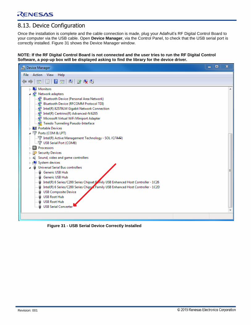
8.13. Device Configuration
Once the installation is complete and the cable connection is made, plug your Adafruit’s RF Digital Control Board to your computer via the USB cable. Open Device Manager, via the Control Panel, to check that the USB serial port is correctly installed. Figure 31 shows the Device Manager window.
NOTE: If the RF Digital Control Board is not connected and the user tries to run the RF Digital Control Software, a pop-up box will be displayed asking to find the library for the device driver.
Figure 31 - USB Serial Device Correctly Installed

RF Products Evaluation Solution Digital Control Software Guide
Revision: 001 34
9. Software Application
9.1. Software Installation
Once the installation is complete, the Software application shortcut will be placed on the user’s desktop.
9.2. Software Interface
The RF Digital Control Software controls the Product EVKIT in both serial, direct parallel, and parallel latched mode.
NOTE: The pop-up box appears notifying that “RF Digital Control Board not found” if user tries to run the RF Digital Control Software without connecting the RF Digital Control Board.
Figure 32 - Software Application
9.2.1. Pin Configuration
This application works for both serial and parallel interfaces. Please refer to the pin configuration in Figure 32 (Number 1) for the correct connection from the RF Digital Control Board to IDT’s Product EVKIT. Latch Enable pins are differentfor different modes of communication.
9.2.2. Device
Choose the device you would like to test using the RF Digital Control Software Application.
9.2.3. Device Mode
Users can choose one of the three modes of communication for the device (Figure 32, Number 3). Please refer to the device datasheet for supported modes of communication. Modes of operation that are not supported by Digital Control Application/device are automatically disabled.
9.2.4. Attenuation Setting
Users can set the desired attenuation using this control. The attenuation step and maximum attenuation are different for each device.

RF Products Evaluation Solution Digital Control Software Guide
Revision: 001 35
9.2.5. Status
Any status or error messages are displayed in this box (Figure 32, Number 5).
9.2.6. Stop
Users can stop the application using the STOP button (Figure 32, Number 6).
9.2.7. Address
The Address control button is not present in Figure 32. It is only visible when the F1956EVB and F1977EVB are selected.
9.2.8. Channel B
The Channel B control is not present in Figure 32. It is only visible when the F1240EVB is selected. The light on this indicator indicates that channel B is selected.
9.3. Parallel Control Option
Please note that the RF Digital Control Software application won’t support parallel mode without running executable “EEPROG” which is located in the folder named “parallel_option”.
9.4. EEPROG
The executable application “EEPROG” programs the CBUS pin of the RF Digital Control Board chip for direct/latched parallel mode. Please note that the user needs to run this application only one time. Once the application programs the RF Digital Control Board chip, product EVB or EVKIT can be controlled using direct parallel and parallel latched mode. The steps for opening the EEPROG application are provided below.
Right click on the “parallel_option” folder then click open. Figure 36 shows the location of the “parallel_option” folder.

RF Products Evaluation Solution Digital Control Software Guide
Revision: 001 36
Figure 33 - location of the “parallel_option” folder
Right click on the “EEPROG.exe” file then click open. The Figure 33 shows the location of the “EEPROG.exe” file.

RF Products Evaluation Solution Digital Control Software Guide
Revision: 001 37
Figure 34 - EEPROG Application Location
Figure 35 shows the EEPROG application interface that needs to be run so that parallel mode can be used.
Figure 35 - EEPROG application for direct/latched parallel mode

RF Products Evaluation Solution Digital Control Software Guide
Revision: 001 38
10. Test Environment
The application has been known to work on a "HP EliteBook 2560p" running "Windows 7 Professional".
11. Supported Devices
Table 20 - Supported devices
Product Product Family Comment Support Date
F1950EVB Digital Step Attenuator Requires cable for connection August 2015
F1951EVB Digital Step Attenuator Requires cable for connection August 2015
F1953EVB Digital Step Attenuator Requires cable for connection August 2015
F1956EVB Digital Step Attenuator Requires cable for connection August 2015
F1912EVB Digital Step Attenuator Requires cable for connection August 2015
F1975EVB Digital Step Attenuator Requires cable for connection August 2015
F1977EVB Digital Step Attenuator Requires cable for connection August 2015
F1200EVB Variable Gain Amplifier Requires cable for connection August 2015
F1240EVB Variable Gain Amplifier Requires cable for connection August 2015
F1241EVB Variable Gain Amplifier Requires cable for connection August 2015
F0480EVB Variable Gain Amplifier Requires cable for connection August 2015

Corporate HeadquartersTOYOSU FORESIA, 3-2-24 Toyosu,Koto-ku, Tokyo 135-0061, Japanwww.renesas.com
Contact InformationFor further information on a product, technology, the most up-to-date version of a document, or your nearest sales office, please visit:www.renesas.com/contact/
TrademarksRenesas and the Renesas logo are trademarks of Renesas Electronics Corporation. All trademarks and registered trademarks are the property of their respective owners.
IMPORTANT NOTICE AND DISCLAIMER
RENESAS ELECTRONICS CORPORATION AND ITS SUBSIDIARIES (“RENESAS”) PROVIDES TECHNICAL SPECIFICATIONS AND RELIABILITY DATA (INCLUDING DATASHEETS), DESIGN RESOURCES (INCLUDING REFERENCE DESIGNS), APPLICATION OR OTHER DESIGN ADVICE, WEB TOOLS, SAFETY INFORMATION, AND OTHER RESOURCES “AS IS” AND WITH ALL FAULTS, AND DISCLAIMS ALL WARRANTIES, EXPRESS OR IMPLIED, INCLUDING, WITHOUT LIMITATION, ANY IMPLIED WARRANTIES OF MERCHANTABILITY, FITNESS FOR A PARTICULAR PURPOSE, OR NON-INFRINGEMENT OF THIRD PARTY INTELLECTUAL PROPERTY RIGHTS.
These resources are intended for developers skilled in the art designing with Renesas products. You are solely responsible for (1) selecting the appropriate products for your application, (2) designing, validating, and testing your application, and (3) ensuring your application meets applicable standards, and any other safety, security, or other requirements. These resources are subject to change without notice. Renesas grants you permission to use these resources only for development of an application that uses Renesas products. Other reproduction or use of these resources is strictly prohibited. No license is granted to any other Renesas intellectual property or to any third party intellectual property. Renesas disclaims responsibility for, and you will fully indemnify Renesas and its representatives against, any claims, damages, costs, losses, or liabilities arising out of your use of these resources. Renesas' products are provided only subject to Renesas' Terms and Conditions of Sale or other applicable terms agreed to in writing. No use of any Renesas resources expands or otherwise alters any applicable warranties or warranty disclaimers for these products.
(Rev.1.0 Mar 2020)
© 2020 Renesas Electronics Corporation. All rights reserved.