Embed Size (px)
Citation preview

RF & mmWave
Selection Guide
2
Overview 4
Who Are We? 4
Our Milestone 4
TMYTEK’s Technology 5
Hardware Technologies 5
TMXLAB Capabilities: 5
Software Technologies 5
Application Block Diagrams 6
Wireless Transceiver 6
Signal Source Development Tool 6
5G Beamforming 7
FMCW Radar System 7
mmWave Design and Consultant Services 8
Customized Defined Projects (CDP) 8
MMIC Design 9
5G mmWave MMIC Roadmap & W-Band Radar MMIC Roadmap 10
BBox™ 12
BBox Building Blocks 12
BBox Architectures 12
AA-Kits 13
ΦA Box 13
BB-Switch 13
UD Box 13
BB-Brain 13
Standard Products 14
Customization Requirement 14
Phase-Locked Oscillators 16
Standard Products 17
Customization Guideline 18
PLDRO 19
Customization Guideline 19
Amplifiers 20
Low Noise Amplifier 20
Power Amplifier 20
Cryogenic Low Noise Amplifier 20
Standard Products 21
Customization Guideline 21
3
Frequency Conversion 22
Frequency Multiplier 22
Mixers 22
Up / Down Converters 22
Standard Products 23
Customization Guideline 24
Digital Controlled Products 25
Digital Controlled Attenuators (DCA) 25
Digital Controlled Filters (DCF) 25
Digital Controlled Phase Shifters (DPS) 25
Digital Controlled Switchesand Matrices (DSW) 25
Standard Products 26
Customization Requirement 26
Passives 27
Baluns 27
Bias Tees 27
DC Blocks 27
Filters 27
Standard Products 28
Customization Guideline 29
Connectors 30
Multi-Coaxial Connectors 30
Nicomatic Micro Connectors 30
Multi-Coaxial Connectors Specification 31
Selection Guideline 32
Nicomatic Connectors Specification 33
Selection Guideline 33
APLL™ 34
Standard Products 35
Useful Design Reference 36
Decibels - Volts - Watts Conversion Table 36
Return Loss Vs. VSWR Table 37
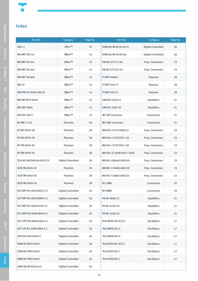
Index 38
4
Overview
Overview
Who Are We?
TMYTEK is a young and enthusiastic team with big dreams. We begin as mmWave experts. Small team but very motivated. As we grow, we become mmWave and software integration experts. Not only can we provide mmWave products and services, we are able to integrate them with software control which makes it very user friendly. But that is not all.
Our journey moved on, as we have a mission. TMYTEK’s mission is to contribute and to realize internet everywhere with our mmWave technology. So we strive to make this dream not only a dream but a reality.
Today, we are the world’s leading 5G beamforming solution provider.
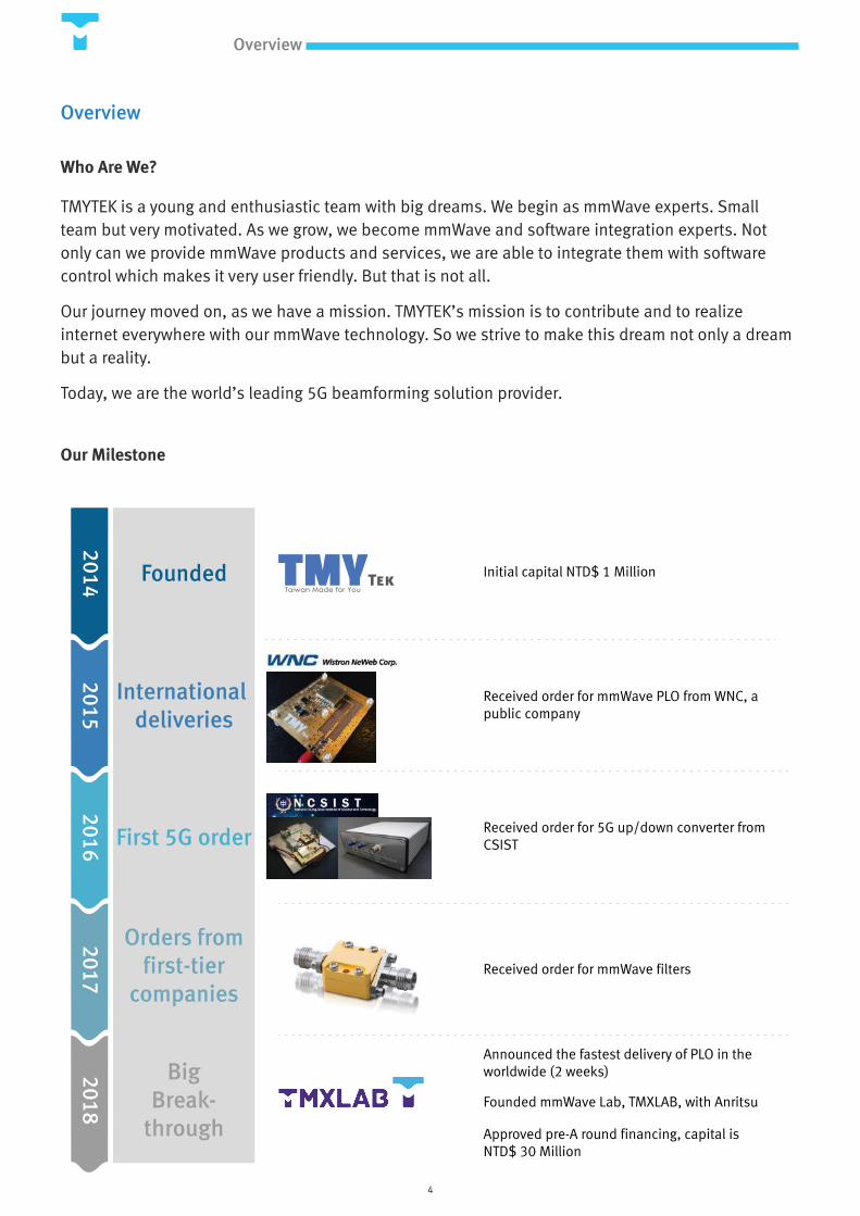
Our Milestone
20142015
20162017
2018
Founded
International deliveries
First 5G order
Orders from first-tier
companies
Big Break-
through
Initial capital NTD$ 1 Million
Received order for mmWave PLO from WNC, a public company
Received order for 5G up/down converter from CSIST
Received order for mmWave filters
Announced the fastest delivery of PLO in the worldwide (2 weeks)
Approved pre-A round financing, capital is NTD$ 30 Million
Founded mmWave Lab, TMXLAB, with Anritsu
5
Technology
TMYTEK’s Technology
Hardware Technologies
Millimeter-wave and RF front end solution is our specialty. TMYTEK has teams with over 10 years of experience in the
mmWave front end component and system designs. We are capable of designing both active and passive components as
well as systems for frequencies up to 110 GHz. On top of that, we can fabricate our designs and do the verification tests
all in our own mmWave laboratory. It is also worth mentioning that we are experts in integrating mmWave components
with software embedded systems.
Some of our expertise includes:
• Design, fabricate and integrate microwave circuits for frequencies up to 110 GHz
• Active and passive circuit designs
• Customized Define Project (CDP) for both component and system level
• Cryogenic electronics designs
• High frequency connector and socket designs
• Housing and waveguide designs
• 5G solution provider
• MMIC designs
TMYTEK’s Capabilities:
• Wire-bonding
• System-in-Package (SiP) micro assembly
• Semiconductor packaging
• Mixed assembly technology
• Thin film microstrip components fabrication
• High Frequency PCB Manufacturing
• Die placement and attachment
• Microwave Consultant
TMXLAB Capabilities (TMYTEK X Anritsu mmWave laboratory) :
• Up to 110 GHz Vector Network Analyzer (VNA)
• Up to 40 GHz Spectrum Analyzer
• 40 GHz Power Meter
• Probe Station
• Wire Bonder
• PCB milling
• DLP FDM 3D Printer
Software Technologies
What makes TMYTEK different from other RF companies is we empower the hardware electronics with software. Our
software experts are skilled in the field of embedded software and application development.
In 5G era, beamforming technology becomes the most critical technique and it requires extensive knowledge of
embedded system control. That’s why TMYTEK can play an important role by building beamforming product like 5G
BBoxTM.
6
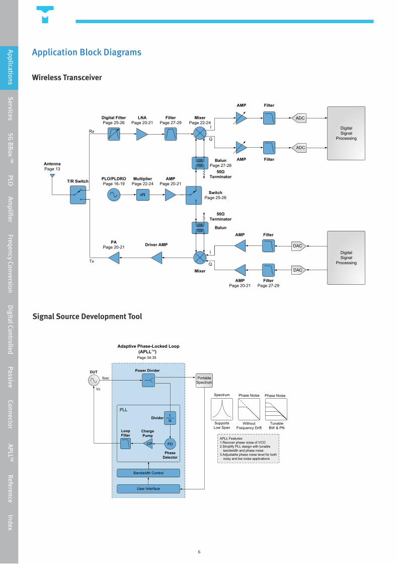
Application Block Diagrams
Wireless Transceiver
Signal Source Development Tool
xN
DigitalSignal
Processing
DigitalSignal
Processing
DAC
DAC
ADC
ADC
Mixer
MixerPage 22-24
I
Q
I
Q
BalunPage 27-28
AMPPage 20-21
MultiplierPage 22-24
PLO/PLDROPage 16-19
LNAPage 20-21
PAPage 20-21
Tx
Driver AMP
Digital FilterPage 25-26
FilterPage 27-29
AntennaPage 13
T/R Switch
Rx
SwitchPage 25-26
Balun
Filter
Filter
Filter
FilterPage 27-29
AMP
AMPPage 20-21
AMP
AMP
50ΩTerminator
50ΩTerminator
Portable Spectrum
Bandwidth Control
User Interface
DUT Power Divider
LoopFilter
CP PD
1N
Adaptive Phase-Locked Loop(APLLTM)
fosc
Vc
PLL
Divider
ChargePump
PhaseDelector
Spectrum Phase Noise Phase Noise
SupportsLow Span
WithoutFrequency Drift
TunableBW & PN
APLL Features:1.Recover phase noise of VCO2.Simplify PLL design with tunable
bandwidth and phase noise3.Adjustable phase noise level for both
noisy and bw noise applications
Page 34-35
Applications Services 5G
BB
ox TM PLO Am
plifier Freqency Conversion Digital Controlled Passive Connector APLL
TM Reference Index
7
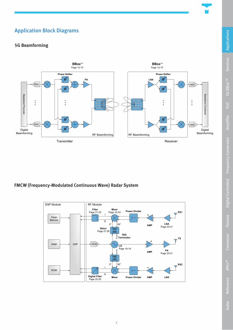
Application Block Diagrams
5G Beamforming
FMCW (Frequency-Modulated Continuous Wave) Radar System
FlashMemory
RAM DSP
RX1
TX
DSP Module RF Module
MOD
ROM
RX2
MixerPage 22-24
FilterPage 27-29
AMP
AMP
AMP
PAPage 20-21
LNA
LNAPage 20-21
LOPage 16-19
Digital FilterPage 25-26
50ΩTerminator
BalunPage 27-28
Power DividerI
Q
I
Q
0° 90°
0° 90°
Mixer Power Divider
Transmitter Receiver
BBoxTM
Φ
Φ
Φ
Φ
Baseband C
ombiner
LNA
RF Beamforming
ADC
ADC
DigitalBeamforming
Φ
Φ
Φ
Φ
DAC
DAC
PA
RF Beamforming
BBoxTM
Baseband P
recoder
DigitalBeamforming
Page 12-15 Page 12-15
Phase ShifterPhase Shifter
Inde
x
R
efer
ence
APL
LTM
Con
nect
or
P
assi
ve
D
igit
al C
ontr
olle
d
Fre
quen
cy C
onve
rsio
n
A
mpl
ifier
PLO
5G
BB
ox TM
Ser
vice
s
A
pplic
atio
ns
8
mmWave Design and Consultant Services
SpecificationEvaluation
Proposed Solution& Budget
CDP Project Request
Finalized DesignPrototype
MassProduction
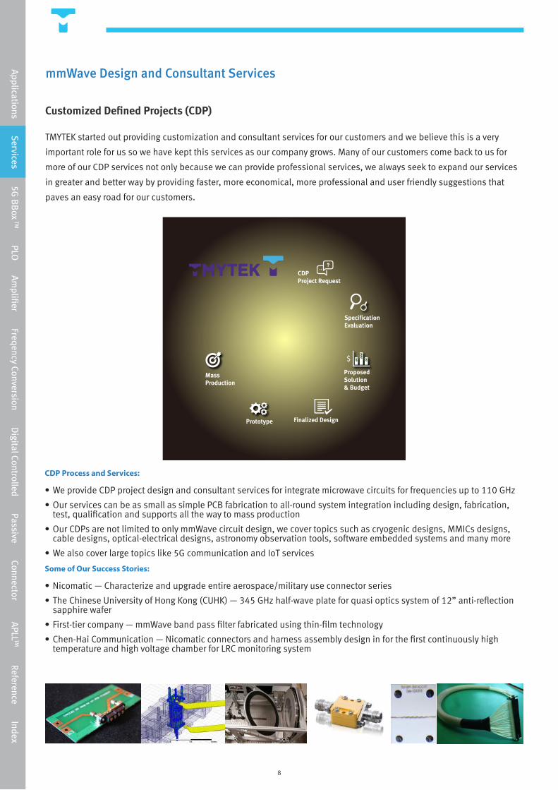
Customized Defined Projects (CDP)
TMYTEK started out providing customization and consultant services for our customers and we believe this is a very
important role for us so we have kept this services as our company grows. Many of our customers come back to us for
more of our CDP services not only because we can provide professional services, we always seek to expand our services
in greater and better way by providing faster, more economical, more professional and user friendly suggestions that
paves an easy road for our customers.
CDP Process and Services:
• We provide CDP project design and consultant services for integrate microwave circuits for frequencies up to 110 GHz
• Our services can be as small as simple PCB fabrication to all-round system integration including design, fabrication, test, qualification and supports all the way to mass production
• Our CDPs are not limited to only mmWave circuit design, we cover topics such as cryogenic designs, MMICs designs, cable designs, optical-electrical designs, astronomy observation tools, software embedded systems and many more
• We also cover large topics like 5G communication and IoT services
Some of Our Success Stories:
• Nicomatic — Characterize and upgrade entire aerospace/military use connector series
• The Chinese University of Hong Kong (CUHK) — 345 GHz half-wave plate for quasi optics system of 12” anti-reflection sapphire wafer
• First-tier company — mmWave band pass filter fabricated using thin-film technology
• Chen-Hai Communication — Nicomatic connectors and harness assembly design in for the first continuously high temperature and high voltage chamber for LRC monitoring system
Applications Services 5G
BB
ox TM PLO Am
plifier Freqency Conversion Digital Controlled Passive Connector APLL
TM Reference Index
9
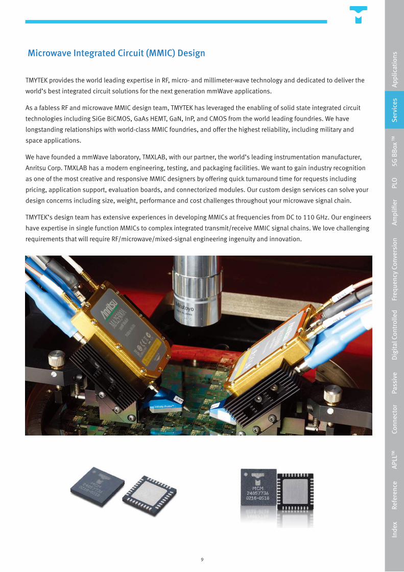
Microwave Integrated Circuit (MMIC) Design
TMYTEK provides the world leading expertise in RF, micro- and millimeter-wave technology and dedicated to deliver the
world’s best integrated circuit solutions for the next generation mmWave applications.
As a fabless RF and microwave MMIC design team, TMYTEK has leveraged the enabling of solid state integrated circuit
technologies including SiGe BiCMOS, GaAs HEMT, GaN, InP, and CMOS from the world leading foundries. We have
longstanding relationships with world-class MMIC foundries, and offer the highest reliability, including military and
space applications.
We have founded a mmWave laboratory, TMXLAB, with our partner, the world’s leading instrumentation manufacturer,
Anritsu Corp. TMXLAB has a modern engineering, testing, and packaging facilities. We want to gain industry recognition
as one of the most creative and responsive MMIC designers by offering quick turnaround time for requests including
pricing, application support, evaluation boards, and connectorized modules. Our custom design services can solve your
design concerns including size, weight, performance and cost challenges throughout your microwave signal chain.
TMYTEK’s design team has extensive experiences in developing MMICs at frequencies from DC to 110 GHz. Our engineers
have expertise in single function MMICs to complex integrated transmit/receive MMIC signal chains. We love challenging
requirements that will require RF/microwave/mixed-signal engineering ingenuity and innovation.
Inde
x
R
efer
ence
APL
LTM
Con
nect
or
P
assi
ve
D
igit
al C
ontr
olle
d
Fre
quen
cy C
onve
rsio
n
A
mpl
ifier
PLO
5G
BB
ox TM
S
ervi
ces
Appl
icat
ions
10
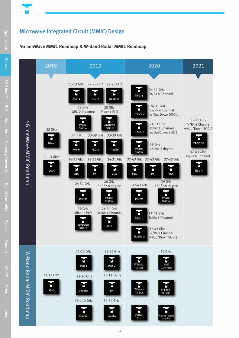
Microwave Integrated Circuit (MMIC) Design
5G mmWave MMIC Roadmap & W-Band Radar MMIC Roadmap
Applications Services 5G
BB
ox TM PLO Am
plifier Freqency Conversion Digital Controlled Passive Connector APLL
TM Reference Index

11
Products
12
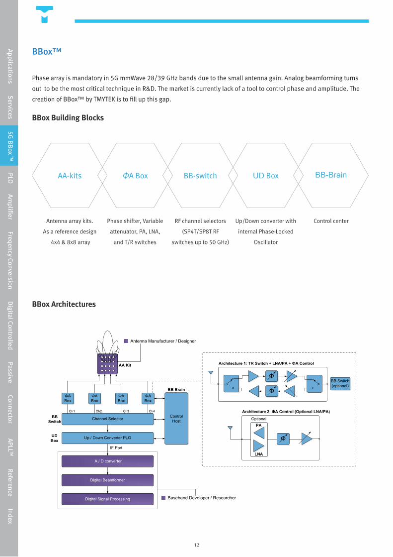
BBox™
Phase array is mandatory in 5G mmWave 28/39 GHz bands due to the small antenna gain. Analog beamforming turns
out to be the most critical technique in R&D. The market is currently lack of a tool to control phase and amplitude. The
creation of BBox™ by TMYTEK is to fill up this gap.
BBox Building Blocks
Applications Services 5G
BB
ox TM PLO Am
plifier Freqency Conversion Digital Controlled Passive Connector APLL
TM Reference Index
BBox Architectures
ΦA Box
ΦA Box
ΦA Box
ΦA Box
Channel Selector
Up / Down Converter PLO
BBSwitch
UDBox
Ch1 Ch2 Ch3 Ch4Control
Host
BB Brain
AA Kit
IF Port
Architecture 1: TR Switch + LNA/PA + ΦA Control
Φ
ΦBB Switch(optional)
Φ
Architecture 2: ΦA Control (Optional LNA/PA)Optional
PA
LNA
Antenna Manufacturer / Designer
Baseband Developer / Researcher
Digital Beamformer
Digital Signal Processing
A / D converter
AA-kits BB-switchΦA Box UD Box BB-Brain
Antenna array kits.
As a reference design
4x4 & 8x8 array
Phase shifter, Variable
attenuator, PA, LNA,
and T/R switches
Up/Down converter with
internal Phase-Locked
Oscillator
Control centerRF channel selectors
(SP4T/SP8T RF
switches up to 50 GHz)
13
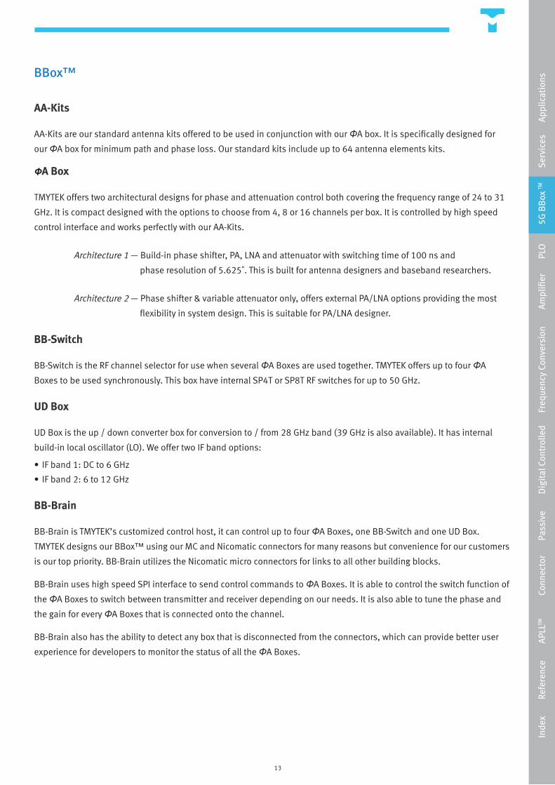
BBox™
AA-Kits
AA-Kits are our standard antenna kits offered to be used in conjunction with our ΦA box. It is specifically designed for
our ΦA box for minimum path and phase loss. Our standard kits include up to 64 antenna elements kits.
ΦA Box
TMYTEK offers two architectural designs for phase and attenuation control both covering the frequency range of 24 to 31
GHz. It is compact designed with the options to choose from 4, 8 or 16 channels per box. It is controlled by high speed
control interface and works perfectly with our AA-Kits.
Architecture 1 — Build-in phase shifter, PA, LNA and attenuator with switching time of 100 ns and
phase resolution of 5.625˚. This is built for antenna designers and baseband researchers.
Architecture 2 — Phase shifter & variable attenuator only, offers external PA/LNA options providing the most
flexibility in system design. This is suitable for PA/LNA designer.
BB-Switch
BB-Switch is the RF channel selector for use when several ΦA Boxes are used together. TMYTEK offers up to four ΦA
Boxes to be used synchronously. This box have internal SP4T or SP8T RF switches for up to 50 GHz.
UD Box
UD Box is the up / down converter box for conversion to / from 28 GHz band (39 GHz is also available). It has internal
build-in local oscillator (LO). We offer two IF band options:
• IF band 1: DC to 6 GHz
• IF band 2: 6 to 12 GHz
BB-Brain
BB-Brain is TMYTEK’s customized control host, it can control up to four ΦA Boxes, one BB-Switch and one UD Box.
TMYTEK designs our BBox™ using our MC and Nicomatic connectors for many reasons but convenience for our customers
is our top priority. BB-Brain utilizes the Nicomatic micro connectors for links to all other building blocks.
BB-Brain uses high speed SPI interface to send control commands to ΦA Boxes. It is able to control the switch function of
the ΦA Boxes to switch between transmitter and receiver depending on our needs. It is also able to tune the phase and
the gain for every ΦA Boxes that is connected onto the channel.
BB-Brain also has the ability to detect any box that is disconnected from the connectors, which can provide better user
experience for developers to monitor the status of all the ΦA Boxes.
Inde
x
R
efer
ence
APL
LTM
Con
nect
or
P
assi
ve
D
igit
al C
ontr
olle
d
Fre
quen
cy C
onve
rsio
n
A
mpl
ifier
PLO
5G
BB
ox TM
Ser
vice
s
App
licat
ions
14
BBox™
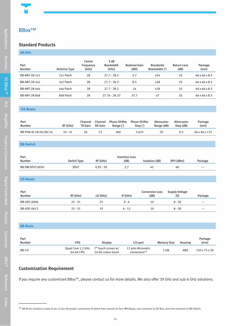
Standard Products
Customization Requirement
If you require any customized BBoxTM, please contact us for more details. We also offer 39 GHz and sub-6 GHz solutions.
2
*1 BB-Brain contains a total of six 12-pin Nicomatic connectors of which four connect to four ΦA Boxes, one connects to UD Box, and one connects to BB-Switch.
ΦA-Boxes
Part Number RF (GHz)
Channel TX Gain
Channel RX Gain
Phase Shifter Range (˚)
Phase Shifter Step (˚)
Attenuator Range (dB)
Attenuator Step (dB)
Package(mm)
BB-PHA-ID-28-04/08/16 24 - 31 26 13 360 5.625 20 0.5 66 x 66 x 132
AA-Kits
Part Number Antenna Type
Centre Frequency
(GHz)
3 dB Bandwidth
(GHz)Realized Gain
(dBi)Broadside
Beamwidth (˚)Return Loss
(dB)Package
(mm)
BB-ANT-28-1x1 1x1 Patch 28 27.7 - 28.3 5.7 ±34 10 66 x 66 x 8.5
BB-ANT-28-2x2 2x2 Patch 28 27.7 - 28.3 8.5 ±28 10 66 x 66 x 8.5
BB-ANT-28-4x4 4x4 Patch 28 27.7 - 28.3 14 ±18 10 66 x 66 x 8.5
BB-ANT-28-8x8 8x8 Patch 28 27.76 - 28.23 21.7 ±7 10 66 x 66 x 8.5
BB-Switch
Part Number Switch Type RF (GHz)
Insertion Loss (dB) Isolation (dB) IIP3 (dBm) Package
BB-SW-SP4T-0050 SP4T 0.05 - 50 2.7 41 40 ---
UD Boxes
PartNumber RF (GHz) LO (GHz) IF (GHz)
Conversion Loss (dB)
Supply Voltage (V) Package
BB-UDC-0006 25 - 31 25 0 - 6 10 8 - 30 ---
BB-UDC-0612 25 - 31 19 6 - 12 10 8 - 30 ---
BB-Brain
PartNumber CPU Display I/O port Memory Size Housing
Package(mm)
BB-CHQuad Core 1.2 GHz
64-bit CPU7” touch screen w/ 24-bit colour touch
12 pins Nicomatic connectors*1
1 GB ABS 150 x 75 x 30
Applications Services 5G
BB
ox TM PLO Am
plifier Freqency Conversion Digital Controlled Passive Connector APLL
TM Reference Index
15
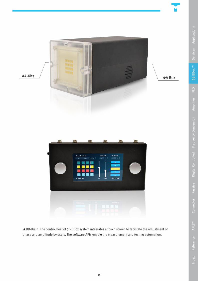
▲BB-Brain: The control host of 5G BBox system integrates a touch screen to facilitate the adjustment of
phase and amplitude by users. The software APIs enable the measurement and testing automation.
AA-Kits ΦA Box
Inde
x
R
efer
ence
APL
LTM
Con
nect
or
P
assi
ve
D
igit
al C
ontr
olle
d
Fre
quen
cy C
onve
rsio
n
A
mpl
ifier
PLO
5G
BB
ox TM
Ser
vice
s
App
licat
ions
16
Phase-Locked Oscillators
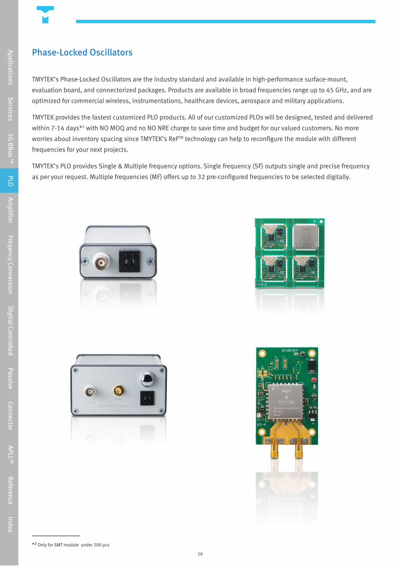
TMYTEK’s Phase-Locked Oscillators are the industry standard and available in high-performance surface-mount,
evaluation board, and connectorized packages. Products are available in broad frequencies range up to 45 GHz, and are
optimized for commercial wireless, instrumentations, healthcare devices, aerospace and military applications.
TMYTEK provides the fastest customized PLO products. All of our customized PLOs will be designed, tested and delivered
within 7-14 days*2 with NO MOQ and no NO NRE charge to save time and budget for our valued customers. No more
worries about inventory spacing since TMYTEK’s ReFTM technology can help to reconfigure the module with different
frequencies for your next projects.
TMYTEK’s PLO provides Single & Multiple frequency options. Single frequency (SF) outputs single and precise frequency
as per your request. Multiple frequencies (MF) offers up to 32 pre-configured frequencies to be selected digitally.
*2 Only for SMT module under 200 pcs
Applications Services 5G
BB
ox TM PLO Am
plifier Freqency Conversion Digital Controlled Passive Connector APLL
TM Reference Index

17
Phase-Locked Oscillators
Standard Products
Single Frequency Series (SFSO)
Part Number
Selectable Frequency Range
(GHz) Pout (dBm)
Phase Noiseat 100 kHz offset(6 GHz) (dBc/Hz)
Supply Voltage(V) Package
PLO-SFSO-B1-S/E/C 1.925 - 16*3 -1 to +8 *4 -92.5 (RF = 6 GHz) -86.5 (RF = 12 GHz)
7 S, E or C *5
PLO-SFSO-B2-C 16 - 32 +10 to +15 -89.2 (RF = 24 GHz)-87.0 (RF = 28 GHz)
7 or 12 Connectorized
PLO-SFSO-B3-C 32 - 45 +12 to +18-77.5 (RF = 32 GHz)-74.1 (RF = 44 GHz)
7 or 12 Connectorized
Multiple Frequency Series (MFSO)
Part Number
Selectable Frequency Range
(GHz)Frequency
sets
Minimum Step Size
(MHz) Pout (dBm)
Phase Noiseat 100 kHz offset(6 GHz) (dBc/Hz)
Supply Voltage
(V) Package
PLO-MFSO-B1-S/E/C 1.925 - 16 *3 Up to 32 1 -1 to +8 *4 -92.5 (RF = 6 GHz) -86.5 (RF = 12 GHz)
7 S, E or C *5
PLO-MFSO-B2-C 16 - 32 Up to 32 2 +10 to +15 -89.2 (RF = 24 GHz)-87.0 (RF = 28 GHz)
7 or 12 Connectorized
PLO-MFSO-B3-C 32 - 45 Up to 32 4 +12 to +18-77.5 (RF = 32 GHz)-74.1 (RF = 44 GHz)
7 or 12 Connectorized
Order example
If you need to order multiple frequency PLO, please list the frequencies you need. For example:
Example 1: 20, 21, 22, 23, 24, 25, 26, 27, 28 GHz (9 frequencies)
Example 2: 20 to 28 GHz (step 1 GHz)
2 3 4
*3 RF 1 frequency range is 1.925 to 8 GHz, RF 2 frequency range is 7.7 to 16 GHz
*4 Pout at RF 1 is +2 to +8 dBm, Pout at RF 2 is -1 to +5 dBm
*5 S for SMT, E for evaluation board, and C for connectorized module
Inde
x
R
efer
ence
APL
LTM
Con
nect
or
P
assi
ve
D
igit
al C
ontr
olle
d
Fre
quen
cy C
onve
rsio
n
A
mpl
ifier
PLO
5G
BB
ox TM
Ser
vice
s
Ap
plic
atio
ns
18
Phase-Locked Oscillators
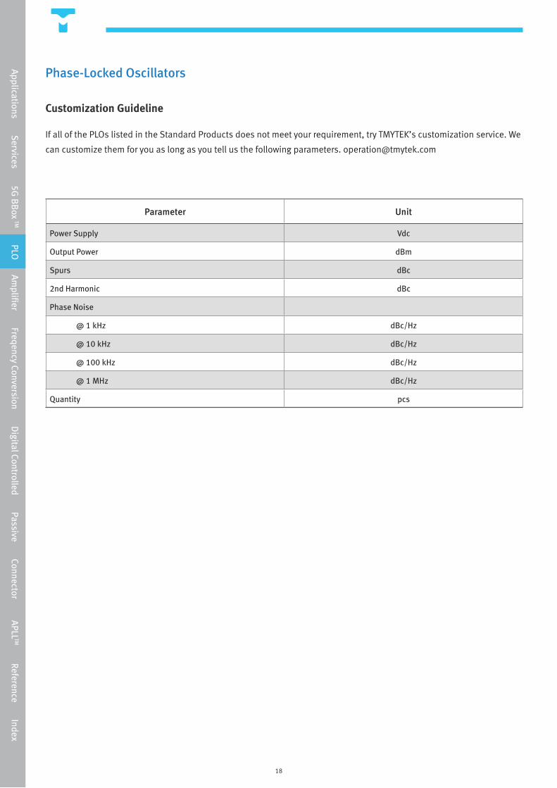
Customization Guideline
If all of the PLOs listed in the Standard Products does not meet your requirement, try TMYTEK’s customization service. We
can customize them for you as long as you tell us the following parameters. [email protected]
Parameter Unit
Power Supply Vdc
Output Power dBm
Spurs dBc
2nd Harmonic dBc
Phase Noise
@ 1 kHz dBc/Hz
@ 10 kHz dBc/Hz
@ 100 kHz dBc/Hz
@ 1 MHz dBc/Hz
Quantity pcs
Applications Services 5G
BB
ox TM PLO Am
plifier Freqency Conversion Digital Controlled Passive Connector APLL
TM Reference Index
19
Phase-Locked Oscillators
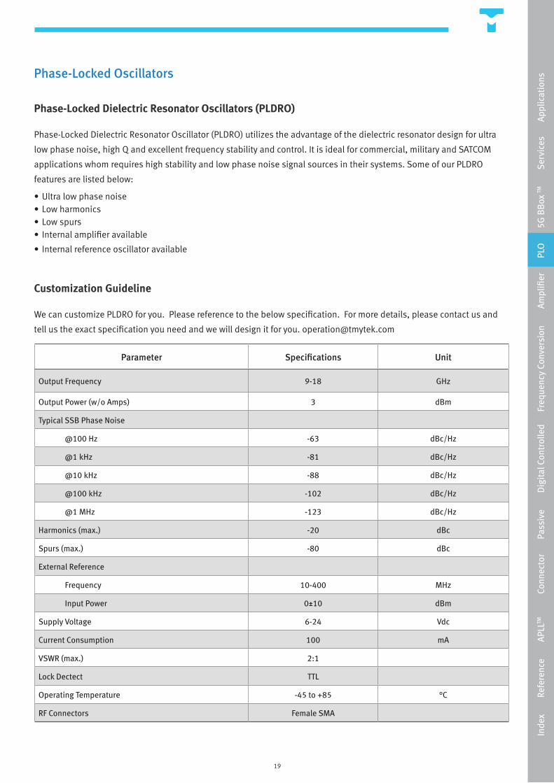
Phase-Locked Dielectric Resonator Oscillators (PLDRO)
Phase-Locked Dielectric Resonator Oscillator (PLDRO) utilizes the advantage of the dielectric resonator design for ultra
low phase noise, high Q and excellent frequency stability and control. It is ideal for commercial, military and SATCOM
applications whom requires high stability and low phase noise signal sources in their systems. Some of our PLDRO
features are listed below:
• Ultra low phase noise• Low harmonics• Low spurs• Internal amplifier available
• Internal reference oscillator available
Customization Guideline
We can customize PLDRO for you. Please reference to the below specification. For more details, please contact us and
tell us the exact specification you need and we will design it for you. [email protected]
Parameter Specifications Unit
Output Frequency 9-18 GHz
Output Power (w/o Amps) 3 dBm
Typical SSB Phase Noise
@100 Hz -63 dBc/Hz
@1 kHz -81 dBc/Hz
@10 kHz -88 dBc/Hz
@100 kHz -102 dBc/Hz
@1 MHz -123 dBc/Hz
Harmonics (max.) -20 dBc
Spurs (max.) -80 dBc
External Reference
Frequency 10-400 MHz
Input Power 0±10 dBm
Supply Voltage 6-24 Vdc
Current Consumption 100 mA
VSWR (max.) 2:1
Lock Dectect TTL
Operating Temperature -45 to +85 °C
RF Connectors Female SMA
Inde
x
R
efer
ence
APL
LTM
Con
nect
or
P
assi
ve
D
igit
al C
ontr
olle
d
Fre
quen
cy C
onve
rsio
n
A
mpl
ifier
PLO
5G
BB
ox TM
Ser
vice
s
Ap
plic
atio
ns
20
Amplifiers
Low Noise Amplifier
Low Noise Amplifiers (LNA) is used in the receiver chain for amplifying received RF signals. It’s function is to ensure
the weak RF signal can be amplified with very minimal noise added. TMYTEK’s low-noise amplifier (LNA) focuses on
the mmWave band for customer’s who are interested in mmWave transceiver and wireless applications. Our LNA’s key
feature is wide band coverage. Our standard LNAs cover the frequency range from 16 GHz to 40 GHz which are suitable
for numerous frequency band requirements. On top of that, they also have excellent noise performance and superior
gain. Some of our LNA’s application includes Point-to-Point radio, SATCOM and wireless communication systems.
Our LNAs are packaged in coaxial connectorized modules which means we have taken care of all the biasing network
including built-in voltage regulation, bias sequencing and reverse bias protection. This simplifies the use of LNA and
makes system integration a step easier.
Power Amplifier
Power Amplifiers (PA) is used in the transmitter chain for amplifying signals to be broadcasted. It’s function is to ensure
RF signal is large enough to be detected. TMYTEK’s power amplifiers (PA) is also made for broadband coverage similar to
our LNA products. Its focus is also on the mmWave band for customers who are interested in mmWave transceiver and
wireless applications. Our standard PAs cover the frequency range from DC to 40 GHz and they feature excellent gain,
high output power and exceptional noise performances. They are most suitable for customers looking for high gain, low
noise figure and wide band coverage amplifiers. This could be applicable to Point-to-Point radio, SATCOM and wireless
communication systems. Our PAs are packaged in coaxial connectorized modules which means we have taken care of all
the biasing network including built-in voltage regulation, bias sequencing and reverse bias protection. This simplifies the
use of PA and makes system integration a step easier.
Cryogenic Low Noise Amplifier
Microwave cryogenic low noise amplifiers (Cryo-LNAs) have been widely used in many applications which requires the
ultra-low receiver noise such as radio astronomy and quantum computing. These amplifiers are designed to operate at
very low temperatures such as 77 Kelvin (-196°C), 15 Kelvin (-258°C), and 4 Kelvin (-269°C). The adapted technologies
for designing these Cryo-LNAs are GaAs pHEMTs, InP HEMTs, and SiGe HBTs. In order to achieve the best noise
performance, all the transistor parameters should be modelled at the cryogenic temperature. TMYTEK has the capabilities
to design the Cryo-LNAs from MMICs to discrete circuits with our own cryogenic models. All the Cryo-LNAs are delivered
with extra precaution designed packages and protective materials are chosen in order to have the best heat sinking and
cooling capabilities.
Applications Services 5G
BB
ox TM PLO Am
plifier Freqency Conversion Digital Controlled Passive Connector APLL
TM Reference Index
21
Amplifiers
Standard Products
Customization Guideline
If all of the LNAs and PAs listed in the Standard Products does not meet your requirement, try TMYTEK’s customization
service. We can customize both Low Noise Amplifiers and Power Amplifier for you as long as you tell us the following
parameters. [email protected]
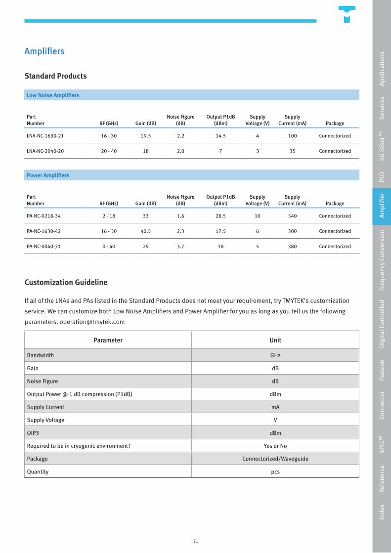
Low Noise Amplifiers
Part Number RF (GHz) Gain (dB)
Noise Figure (dB)
Output P1dB(dBm)
Supply Voltage (V)
Supply Current (mA) Package
LNA-NC-1630-21 16 - 30 19.5 2.2 14.5 4 100 Connectorized
LNA-NC-2040-20 20 - 40 18 2.0 7 3 35 Connectorized
Power Amplifiers
Part Number RF (GHz) Gain (dB)
Noise Figure (dB)
Output P1dB(dBm)
Supply Voltage (V)
Supply Current (mA) Package
PA-NC-0218-34 2 - 18 33 1.6 28.5 10 540 Connectorized
PA-NC-1630-42 16 - 30 40.5 2.3 17.5 6 300 Connectorized
PA-NC-0040-31 0 - 40 29 3.7 18 5 380 Connectorized
Parameter Unit
Bandwidth GHz
Gain dB
Noise Figure dB
Output Power @ 1 dB compression (P1dB) dBm
Supply Current mA
Supply Voltage V
OIP3 dBm
Required to be in cryogenic environment? Yes or No
Package Connectorized/Waveguide
Quantity pcs
Inde
x
R
efer
ence
APL
LTM
Con
nect
or
P
assi
ve
D
igit
al C
ontr
olle
d
Fre
quen
cy C
onve
rsio
n
A
mpl
ifier
PLO
5G
BB
ox TM
Ser
vice
s
Ap
plic
atio
ns
22
Frequency Conversion
Frequency Multiplier
A frequency multiplier is a nonlinear device that is capable of producing an output signal that is at integer multiples
of the input signal frequency. For an integer multiple of two, it is also commonly known as ‘doubler’. The output of a
frequency multiplier is known as the ‘harmonic’ of the fundamental signal in which the ‘fundamental’ frequency is the
input frequency. Hence, when selecting a frequency multiplier, we are often interested in their conversion loss between
the fundamental and the desired harmonic, suppression of undesired harmonics, and power generated at the output.
TMYTEK’s mmWave multipliers cover the RF frequency range from 15 to 45 GHz and are packaged in our own miniature
designed package.
Mixers
A RF/mmWave mixer translates the input signal frequency to an output signal of a different frequency. The translation
can be either from a lower frequency to a higher frequency or vice versa. It is worth noting that the important factors that
we look for in mixers are its’ conversion loss, multi-tone intermodulation products, single tone spurious products, and
isolations. These are all parameters that could affect the dynamic range of a RF/mmWave system. TMYTEK’s standard
mixers cover the frequency range from 10 to 86 GHz and have excellent conversion loss/gain. It is also packaged in our in
house designed connectorized modules which is very compact in size.
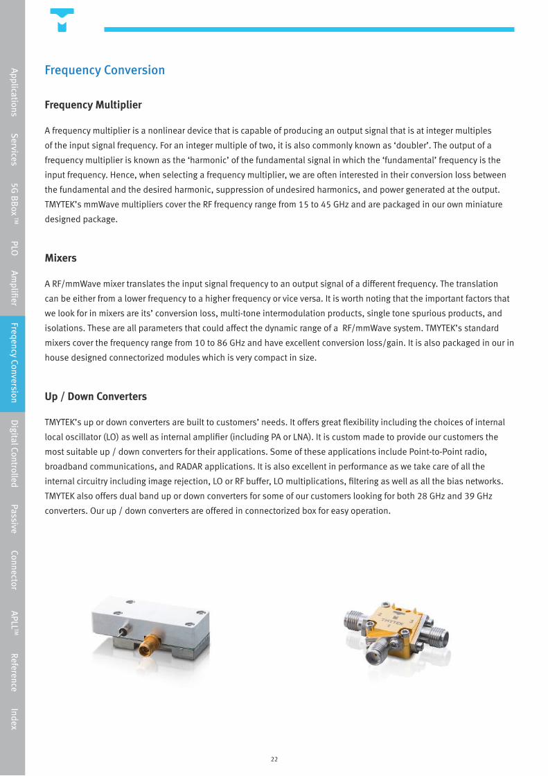
Up / Down Converters
TMYTEK’s up or down converters are built to customers’ needs. It offers great flexibility including the choices of internal
local oscillator (LO) as well as internal amplifier (including PA or LNA). It is custom made to provide our customers the
most suitable up / down converters for their applications. Some of these applications include Point-to-Point radio,
broadband communications, and RADAR applications. It is also excellent in performance as we take care of all the
internal circuitry including image rejection, LO or RF buffer, LO multiplications, filtering as well as all the bias networks.
TMYTEK also offers dual band up or down converters for some of our customers looking for both 28 GHz and 39 GHz
converters. Our up / down converters are offered in connectorized box for easy operation.
Applications Services 5G
BB
ox TM PLO Am
plifier Freqency Conversion Digital Controlled Passive Connector APLL
TM Reference Index
23
Frequency Conversion
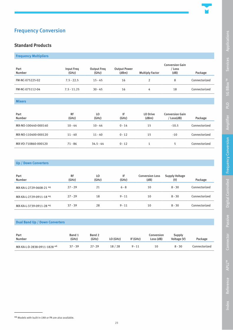
Standard Products
Dual Band Up / Down Converters
Part Number
Band 1(GHz)
Band 2 (GHz) LO (GHz) IF (GHz)
Conversion Loss (dB)
Supply Voltage (V) Package
MX-KA-L-D-2838-0911-1828 *6 37 - 39 27- 29 18 / 28 9 - 11 10 8 - 30 Connectorized
Frequency Multipliers
Part Number
Input Freq (GHz)
Output Freq (GHz)
Output Power (dBm) Multiply Factor
Conversion Gain / Loss (dB) Package
FM-NC-075225-02 7.5 - 22.5 15 - 45 16 2 8 Connectorized
FM-NC-075112-04 7.5 - 11.25 30 - 45 16 4 18 Connectorized
Mixers
PartNumber
RF (GHz)
LO(GHz)
IF (GHz)
LO Drive(dBm)
Conversion Gain / Loss(dB) Package
MX-NO-100440-000140 10 - 44 10 - 44 0 - 14 15 -10.5 Connectorized
MX-NO-110400-000120 11 - 40 11 - 40 0 - 12 15 -10 Connectorized
MX-VO-710860-000120 71 - 86 34.5 - 44 0 - 12 1 5 Connectorized
Up / Down Converters
Part Number
RF (GHz)
LO (GHz)
IF (GHz)
Conversion Loss (dB)
Supply Voltage (V) Package
MX-KA-L-2729-0608-21 *6 27 - 29 21 6 - 8 10 8 - 30 Connectorized
MX-KA-L-2729-0911-18 *6 27 - 29 18 9 - 11 10 8 - 30 Connectorized
MX-KA-L-3739-0911-28 *6 37 - 39 28 9 - 11 10 8 - 30 Connectorized
2
*6 Models with built-in LNA or PA are also available.
Inde
x
R
efer
ence
APL
LTM
Con
nect
or
P
assi
ve
D
igit
al C
ontr
olle
d
Fre
quen
cy C
onve
rsio
n
A
mpl
ifier
PLO
5G
BB
ox TM
Ser
vice
s
Ap
plic
atio
ns
24
Frequency Conversion
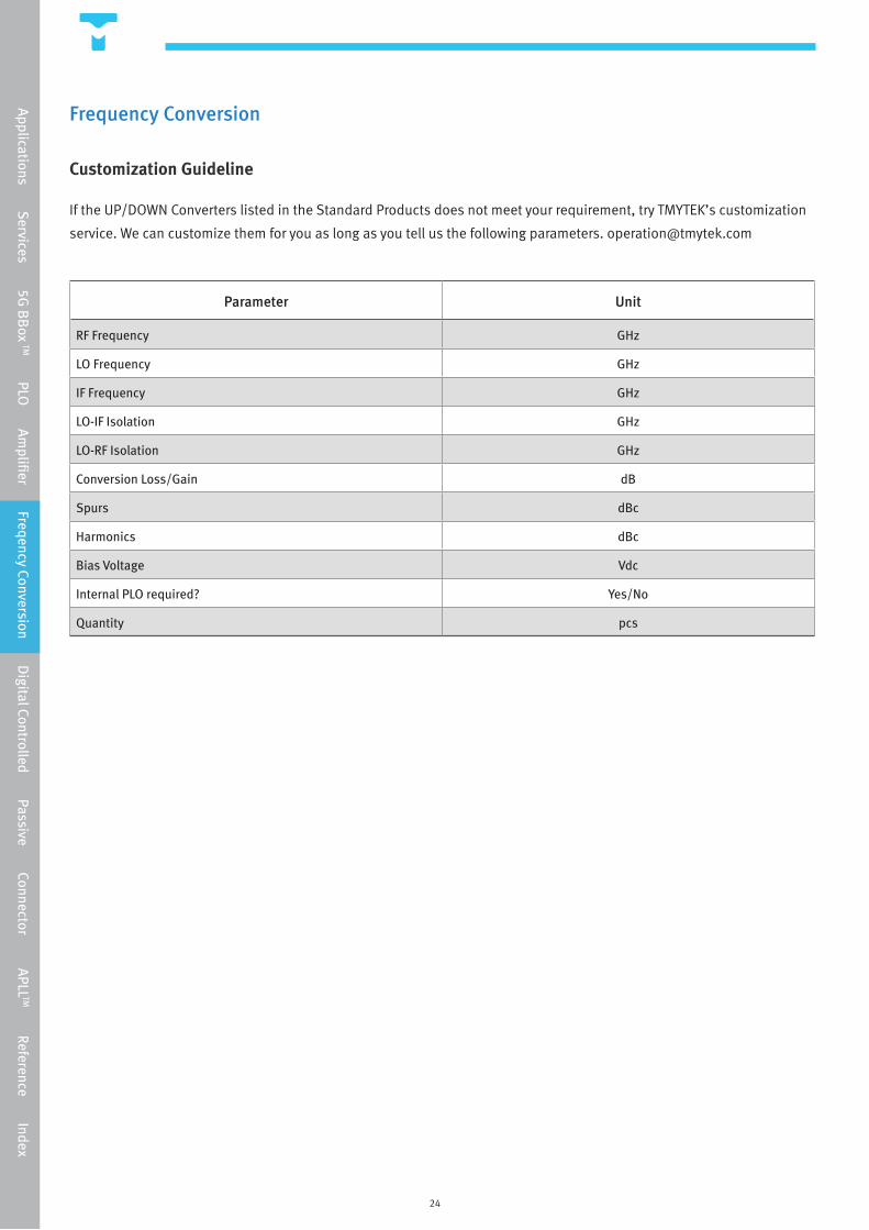
Customization Guideline
If the UP/DOWN Converters listed in the Standard Products does not meet your requirement, try TMYTEK’s customization
service. We can customize them for you as long as you tell us the following parameters. [email protected]
Parameter Unit
RF Frequency GHz
LO Frequency GHz
IF Frequency GHz
LO-IF Isolation GHz
LO-RF Isolation GHz
Conversion Loss/Gain dB
Spurs dBc
Harmonics dBc
Bias Voltage Vdc
Internal PLO required? Yes/No
Quantity pcs
Applications Services 5G
BB
ox TM PLO Am
plifier Freqency Conversion Digital Controlled Passive Connector APLL
TM Reference Index
25
Digital Controlled Products
Digital Controlled Attenuators (DCA)
TMYTEK’s standard digital controlled attenuator operates in the frequency range up to 30 GHz. It is a 6 bit digital
attenuator capable of attenuating up to 31.5 dB with a minimum of 0.5 dB per step. Digital controlled attenuators can
be used in variety of applications including automotive, wireless (including 5G communication) and radar. Our DCA
is typically controlled by TTL but we also offer USB control as an option. The packaging of DCAs are in house designed
connectorized modules.
Digital Controlled Filters (DCF)
We are typically used to designing filters at our band of interest. But when there are more and more demands for
applications such as multi-band transceivers or multi-standard communication systems, it became crucial for us to
develop filters that can be used in multiple scenarios. This is why digital controlled filters became essential. TMYTEK
offers a wide selection of digital controlled filters including low pass filters, high pass filters and band pass filters. Our
DCF operates up to 18 GHz with excellent performances such as low insertion loss. Our DCF range from 4 to 9 bit control
and is typically controlled by TTL but we also offer USB control as an option. The packaging of DCFs are in house designed
connectorized modules.
Digital Controlled Phase Shifters (DPS)
TMYTEK’s digital controlled phase shifters are developed for use with the 5G beamforming system particularly in the 28
GHz band. The operating frequency ranges from 26.5 to 30.5 GHz with excellent phase and amplitude accuracy across
the nominal frequency band. The phase shifter is a 6 bit control covering 360˚ with 5.625˚ per step. The attenuation
control is 5 bit; each step is 0.7 dB with a maximum of 21.7 dB attenuation. Our DPS is a passive device and it follows
the T/R structure and exhibits only two RF ports and the control port. Our DPS is typically controlled by USB. The
packaging of DPSs are in house designed connectorized modules.
Digital Controlled Switches and Matrices (DSW)
TMYTEK’s digital controlled switch series covers a broad range of switches including standard frequency switches, such
as SPDT, SP4T and SP8T and switch matrices, such as 2x2 matrix, 4x4 matrix and 8x8 matrix. They all have one advantage
in common and that is wideband coverage. The standard frequency switches cover the frequency range from 50 MHz all
the way up to 50 GHz while the switch matrices covers up to 18 GHz. Some of the important parameters worth noting
is that they have low insertion loss and excellent isolation. We also offer special edition switch matrix which includes
all of the switching features of the 2x2 matrix and on top of that the input ports and the output ports are all internally
switchable. Our DSWs are typically controlled by USB. The packaging of DSWs are in house designed connectorized
modules.
Inde
x
R
efer
ence
APL
LTM
Con
nect
or
P
assi
ve
D
igit
al C
ontr
olle
d
Fre
quen
cy C
onve
rsio
n
A
mpl
ifier
PLO
5G
BB
ox TM
Ser
vice
s
Ap
plic
atio
ns

26
Digital Controlled Products
Standard Products
Customization Requirement
If you can’t find what you are looking for in the Standard Products, try TMYTEK’s customization services. Please send your
requirements to [email protected] 2
*7 Special edition. Please ask for more details.
Digital Controlled Attenuators
Part Number RF (GHz) Bit Count
Attenuator Range (dB)
Attenuator Step (dB)
Insertion Loss (dB) IIP3 (dBm) Package
DCA-NC-000300-06-005315 0 - 30 6 0 - 31.5 0.5 7.5 38 Connectorized
Digital Controlled Switches and Matrices
Part Number Switch Type RF (GHz)
Insertion Loss (dB) Isolation (dB) IIP3 (dBm) Package
DSW-NC-SPDT-0050 SPDT 0.05 - 50 2.5 47 — Connectorized
DSW-NC-SP4T-0050 SP4T 0.05 - 50 2.5 41 40 Connectorized
DSW-NC-SP8T-0050 SP8T 0.05 - 50 3.5 32 40 Connectorized
DSW-QU-M-0018-2x2 2x2 Matrix 0 - 18 2.5 55 59 Connectorized
DSW-QU-M-0018-2x2-S *7 2x2 Matrix 0 - 18 2.5 55 59 Connectorized
DSW-QU-M-0018-4x4 4x4 Matrix 0 - 18 2.5 55 59 Connectorized
Digital Controlled Filters
Part Number Filter Type Bit Count
Tunable Frequency
Range (GHz)Insertion Loss
(dB)Rejection
(dB)IIP3
(dBm) Package
DCF-BPF-B1-00220042-5-C Band Pass 5 0.22 - 0.425 7 46 / 50 40 Connectorized
DCF-BPF-B1-00430089-5-C Band Pass 5 0.43 - 0.89 5.5 30 / 54 42 Connectorized
DCF-BPF-B1-00630140-5-C Band Pass 5 0.63 - 1.4 6 32 / 53 37.5 Connectorized
DCF-BPF-B3-06001800-9-C Band Pass 9 6 - 18 3 50 40 Connectorized
DCF-HPF-B3-06001000-4-C High Pass 4 6 - 10 2.5 50 40 Connectorized
DCF-LPF-B3-09001800-5-C Low Pass 5 9 - 18 3 50 40 Connectorized
Digital Controlled Phase Shifter
Part Number RF (GHz)
Phase Shifter Range (˚)
Phase Shifter Step (˚)
Attenuator Range (dB)
Attenuator Step (dB) Package
DPS-PO-02650305-C 26.5 - 30.5 0 - 360 5.625 0 - 21.7 0.7 Connectorized
Applications Services 5G
BB
ox TM PLO Am
plifier Freqency Conversion Digital Controlled Passive Connector APLL
TM Reference Index
27
Passives
Baluns
TMYTEK’s mmWave balance to unbalance transformer (BULUN) is made to convert a differential signal to a single ended
signal and vice versa, which is functionally equivalent to a 180˚ hybrid. It operates in the frequency range of 11 to 16 GHz
providing superior amplitude balance, phase balance, insertion loss and isolation. Our BALUNs are packaged in our in
house designed connectorized modules.
Bias Tees
TMYTEK’s bias tee offers the ability to apply or detect a DC voltage on a RF signal for frequency coverages up to 50 GHz.
It is made to cover the high frequency bands for mmWave applications. Some of our bias tees advantages include low
insertion loss, excellent return loss between the RF and the common ports as well as superior power handling for both
the DC and the RF port. Our bias tees are packaged in our in house designed connectorized modules.
DC Blocks
A DC block offers the ability to prevent (or block) the flow of direct current (DC) frequencies to RF signals. TMYTEK’s DC
blocks are made with great precision for frequency coverages up to 50 GHz at the same time providing low insertion loss,
high blockage and superior DC power handling. Our DC blocks are available in different RF connector sizes for direct
coaxial connections, including SMA connector, 2.92 mm (or K) connector and 2.4 mm (or V) connector. They are made to
cover the different frequency bands for various mmWave applications.
Filters
Filters are a fundamental component in signal processing and it appears in numerous stages of the RF and mmWave
systems. Their main functionality are to pass signals within their passband and reject signals outside the passband in
term to provide ‘filtering’ to the wanted signal. Most of our filters are custom made for our customers to fit the specific
needs for their applications in different bands of the spectrum. TMYTEK’s filters offers superior rejection, low insertion
loss, and excellent return loss. They are also compact in sizes for we designed the packaging ourselves in connectorized
modules. Our standard filters cover the frequency range up to 53 GHz, but please refer to our customization guideline for
more choices that we can offer.
Inde
x
R
efer
ence
APL
LTM
Con
nect
or
P
assi
ve
D
igit
al C
ontr
olle
d
Fre
quen
cy C
onve
rsio
n
A
mpl
ifier
PLO
5G
BB
ox TM
Ser
vice
s
Ap
plic
atio
ns
28
Passives
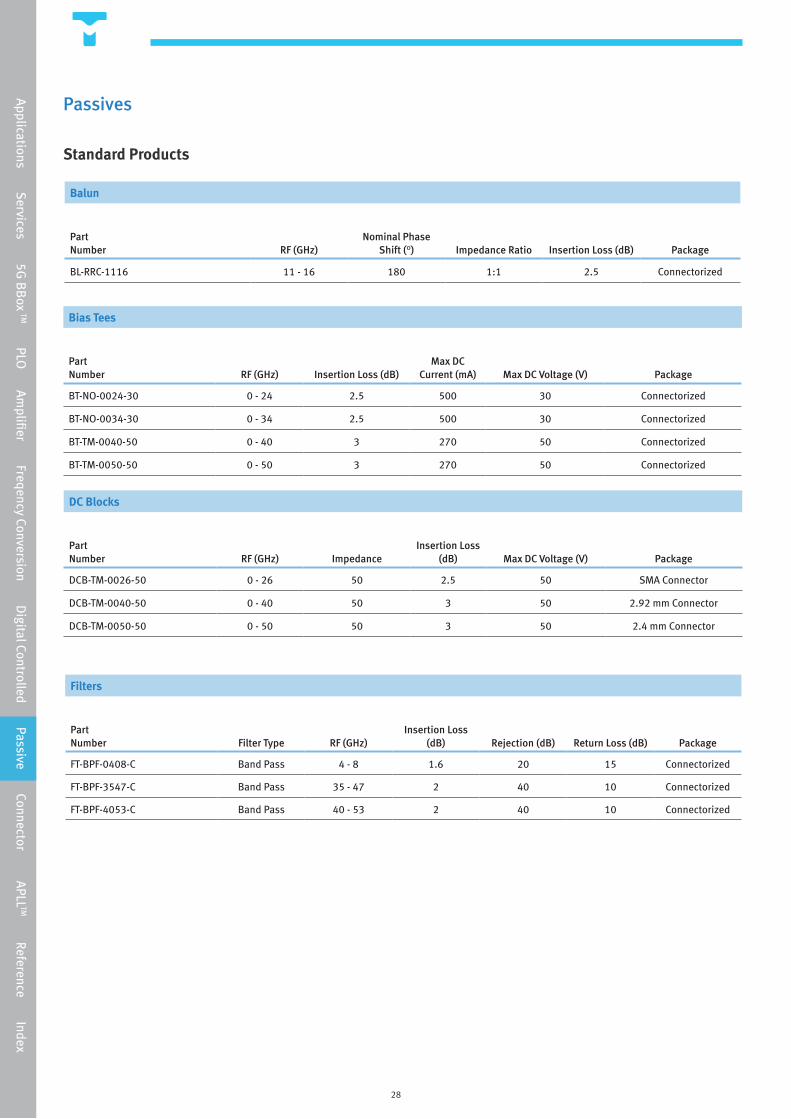
Standard Products
Balun
Part Number RF (GHz)
Nominal Phase Shift (°) Impedance Ratio Insertion Loss (dB) Package
BL-RRC-1116 11 - 16 180 1:1 2.5 Connectorized
Filters
Part Number Filter Type RF (GHz)
Insertion Loss (dB) Rejection (dB) Return Loss (dB) Package
FT-BPF-0408-C Band Pass 4 - 8 1.6 20 15 Connectorized
FT-BPF-3547-C Band Pass 35 - 47 2 40 10 Connectorized
FT-BPF-4053-C Band Pass 40 - 53 2 40 10 Connectorized
Bias Tees
Part Number RF (GHz) Insertion Loss (dB)
Max DC Current (mA) Max DC Voltage (V) Package
BT-NO-0024-30 0 - 24 2.5 500 30 Connectorized
BT-NO-0034-30 0 - 34 2.5 500 30 Connectorized
BT-TM-0040-50 0 - 40 3 270 50 Connectorized
BT-TM-0050-50 0 - 50 3 270 50 Connectorized
DC Blocks
Part Number RF (GHz) Impedance
Insertion Loss (dB) Max DC Voltage (V) Package
DCB-TM-0026-50 0 - 26 50 2.5 50 SMA Connector
DCB-TM-0040-50 0 - 40 50 3 50 2.92 mm Connector
DCB-TM-0050-50 0 - 50 50 3 50 2.4 mm Connector
Applications Services 5G
BB
ox TM PLO Am
plifier Freqency Conversion Digital Controlled Passive Connector APLL
TM Reference Index
29
Passives
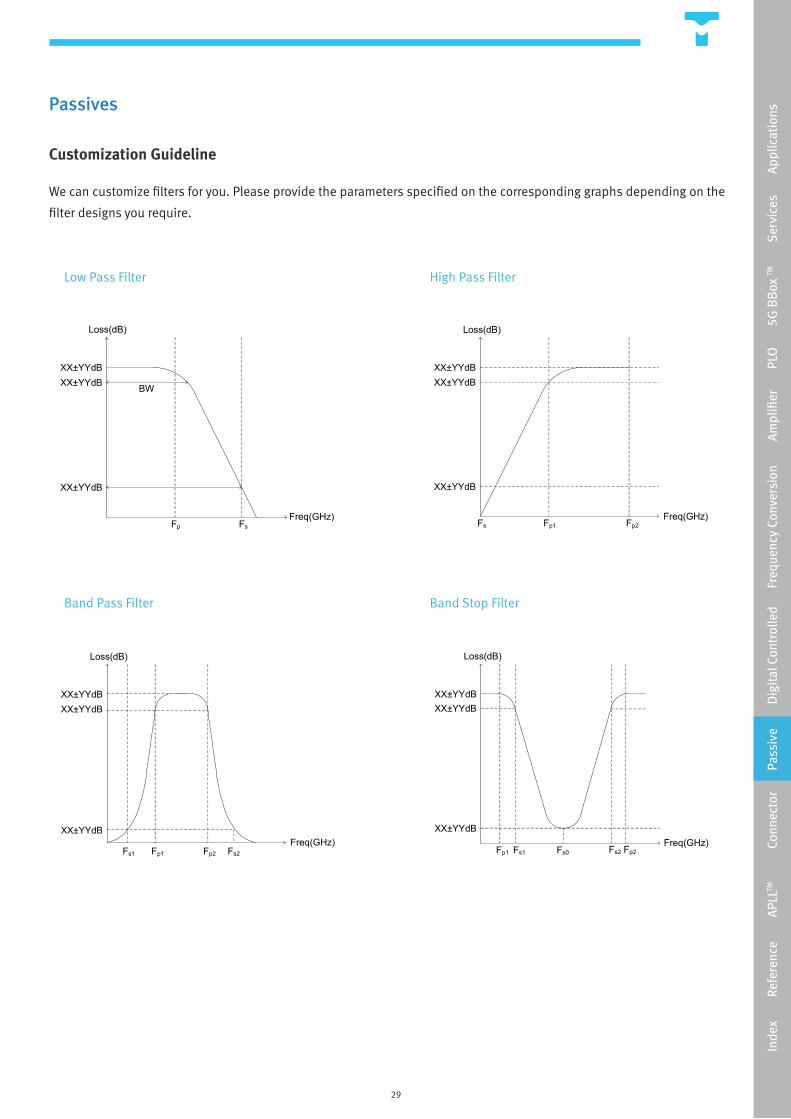
Customization Guideline
We can customize filters for you. Please provide the parameters specified on the corresponding graphs depending on the
filter designs you require.
XX±YYdBXX±YYdB
XX±YYdB
Fp Fs
BW
Loss(dB)
Freq(GHz)
XX±YYdBXX±YYdB
XX±YYdB
Fp1 Fp2
Loss(dB)
FsFreq(GHz)
XX±YYdBXX±YYdB
XX±YYdB
Loss(dB)
Freq(GHz)Fp1 Fp2Fs1 Fs2
XX±YYdBXX±YYdB
XX±YYdB
Loss(dB)
Fp1 Fp2Fs1 Fs2Fs0Freq(GHz)
Low Pass Filter
Band Pass Filter
High Pass Filter
Band Stop Filter
Inde
x
R
efer
ence
APL
LTM
Con
nect
or
P
assi
ve
D
igit
al C
ontr
olle
d
Fre
quen
cy C
onve
rsio
n
A
mpl
ifier
PLO
5G
BB
ox TM
Ser
vice
s
Ap
plic
atio
ns
30
Connectors
Multi-Coaxial Connectors
TMYTEK offers two connector product lines each with its own specialized advantages. The first product line is the
multi-coaxial (MC) connectors. This product line provides customers to combine coaxial connections into a compact
connector form. In addition, we let our customer choose how many coaxial ports they need; in another words, they
are customizable. Our multi-coaxial connectors provide the choices between 2 to 16 connectors in 1 or 2 row formats.
This outstanding feature makes the connectors compact which saves time, space and money for our customers when
designing and using coaxial connections. On top of our customizable feature, the connector’s RF performances are also
worth noting. It has excellent insertion loss and return loss performances and can operate up to 50 GHz.
Nicomatic Micro Connectors
TMYTEK is a distributor of Nicomatic’s micro connectors. Both CMM and DMM series. These connectors have aerospace/
military standards and are ISO9001 and AS/EN/JISQ 9100 certified. They have high working voltages and can withstand
currents up to 3 A. Furthermore, the CMM series is high temperature resistant (up to 260˚C). We provide design-in
services for customers who wish to design their system with Nicomatic micro connectors.
Applications Services 5G
BB
ox TM PLO Am
plifier Freqency Conversion Digital Controlled Passive Connector APLL
TM Reference Index
31
Connectors
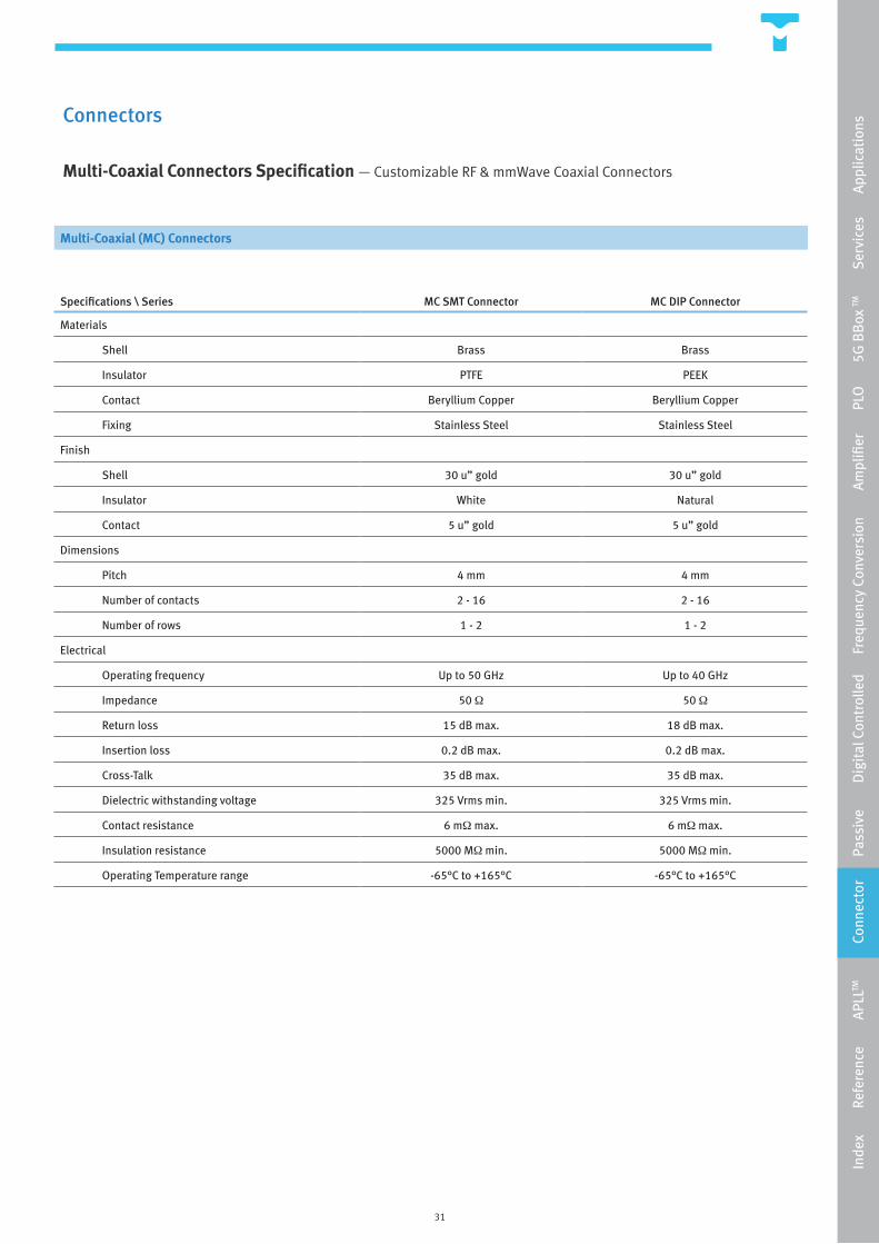
Multi-Coaxial Connectors Specification — Customizable RF & mmWave Coaxial Connectors
Multi-Coaxial (MC) Connectors
Specifications \ Series MC SMT Connector MC DIP Connector
Materials
Shell Brass Brass
Insulator PTFE PEEK
Contact Beryllium Copper Beryllium Copper
Fixing Stainless Steel Stainless Steel
Finish
Shell 30 u” gold 30 u” gold
Insulator White Natural
Contact 5 u” gold 5 u” gold
Dimensions
Pitch 4 mm 4 mm
Number of contacts 2 - 16 2 - 16
Number of rows 1 - 2 1 - 2
Electrical
Operating frequency Up to 50 GHz Up to 40 GHz
Impedance 50 Ω 50 Ω
Return loss 15 dB max. 18 dB max.
Insertion loss 0.2 dB max. 0.2 dB max.
Cross-Talk 35 dB max. 35 dB max.
Dielectric withstanding voltage 325 Vrms min. 325 Vrms min.
Contact resistance 6 mΩ max. 6 mΩ max.
Insulation resistance 5000 MΩ min. 5000 MΩ min.
Operating Temperature range -65°C to +165°C -65°C to +165°C
Inde
x
R
efer
ence
APL
LTM
Con
nect
or
P
assi
ve
D
igit
al C
ontr
olle
d
Fre
quen
cy C
onve
rsio
n
A
mpl
ifier
PLO
5G
BB
ox TM
Ser
vice
s
Ap
plic
atio
ns
32
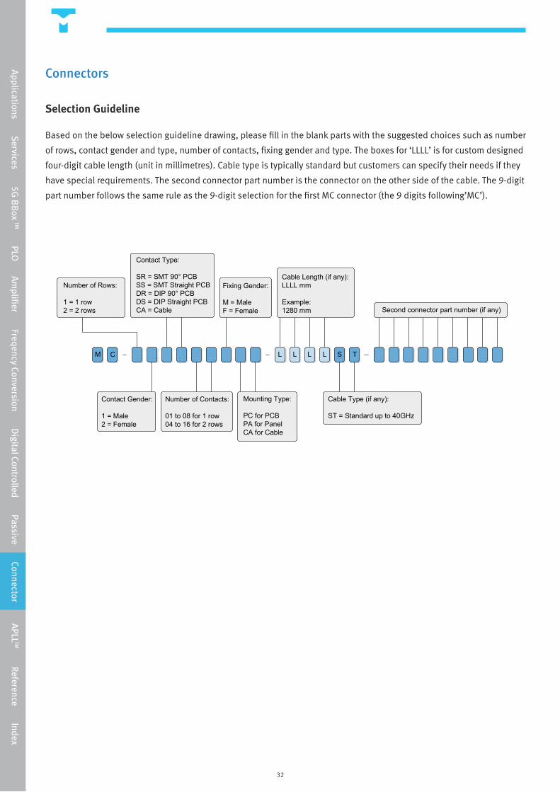
Number of Rows:
1 = 1 row2 = 2 rows
Contact Gender:
1 = Male2 = Female
Contact Type:
SR = SMT 90° PCBSS = SMT Straight PCBDR = DIP 90° PCBDS = DIP Straight PCBCA = Cable
Number of Contacts:
01 to 08 for 1 row04 to 16 for 2 rows
Fixing Gender:
M = MaleF = Female
Mounting Type:
PC for PCBPA for PanelCA for Cable
Cable Length (if any):LLLL mm
Example:1280 mm
L L L L S T
Cable Type (if any):
ST = Standard up to 40GHz
Second connector part number (if any)
M C
Connectors
Selection Guideline
Based on the below selection guideline drawing, please fill in the blank parts with the suggested choices such as number
of rows, contact gender and type, number of contacts, fixing gender and type. The boxes for ‘LLLL’ is for custom designed
four-digit cable length (unit in millimetres). Cable type is typically standard but customers can specify their needs if they
have special requirements. The second connector part number is the connector on the other side of the cable. The 9-digit
part number follows the same rule as the 9-digit selection for the first MC connector (the 9 digits following’MC’).
Applications Services 5G
BB
ox TM PLO Am
plifier Freqency Conversion Digital Controlled Passive Connector APLL
TM Reference Index
33
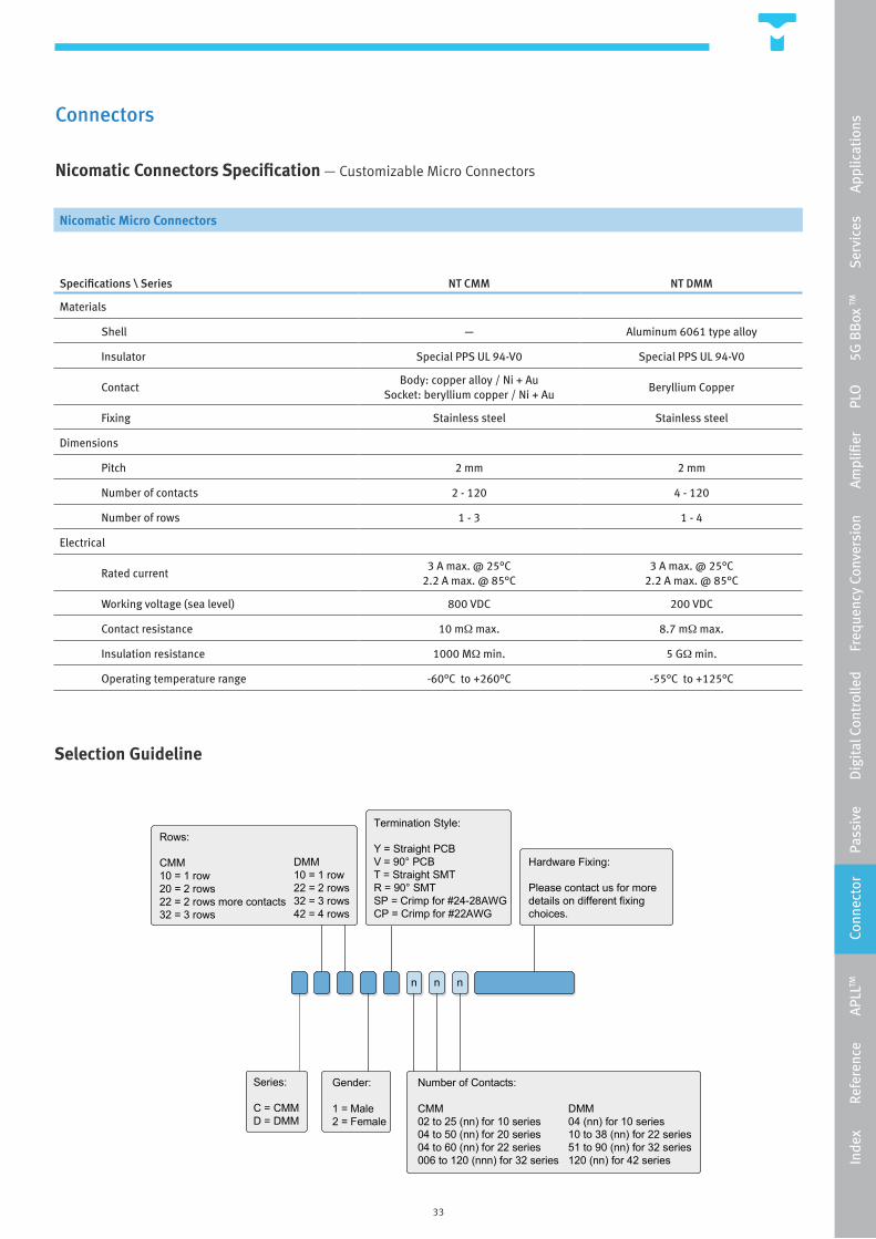
Number of Contacts:
CMM02 to 25 (nn) for 10 series04 to 50 (nn) for 20 series04 to 60 (nn) for 22 series006 to 120 (nnn) for 32 series
Termination Style:
Y = Straight PCBV = 90° PCBT = Straight SMTR = 90° SMTSP = Crimp for #24-28AWGCP = Crimp for #22AWG
n nn
Gender:
1 = Male2 = Female
Rows:
CMM10 = 1 row20 = 2 rows22 = 2 rows more contacts32 = 3 rows
Series:
C = CMMD = DMM
Hardware Fixing:
Please contact us for more details on different fixing choices.
DMM04 (nn) for 10 series10 to 38 (nn) for 22 series51 to 90 (nn) for 32 series120 (nn) for 42 series
DMM10 = 1 row22 = 2 rows32 = 3 rows42 = 4 rows
Connectors
Nicomatic Connectors Specification — Customizable Micro Connectors
Nicomatic Micro Connectors
Specifications \ Series NT CMM NT DMM
Materials
Shell — Aluminum 6061 type alloy
Insulator Special PPS UL 94-V0 Special PPS UL 94-V0
ContactBody: copper alloy / Ni + Au
Socket: beryllium copper / Ni + AuBeryllium Copper
Fixing Stainless steel Stainless steel
Dimensions
Pitch 2 mm 2 mm
Number of contacts 2 - 120 4 - 120
Number of rows 1 - 3 1 - 4
Electrical
Rated current3 A max. @ 25°C
2.2 A max. @ 85°C3 A max. @ 25°C
2.2 A max. @ 85°C
Working voltage (sea level) 800 VDC 200 VDC
Contact resistance 10 mΩ max. 8.7 mΩ max.
Insulation resistance 1000 MΩ min. 5 GΩ min.
Operating temperature range -60°C to +260°C -55°C to +125°C
Selection Guideline
Inde
x
R
efer
ence
APL
LTM
Con
nect
or
P
assi
ve
D
igit
al C
ontr
olle
d
Fre
quen
cy C
onve
rsio
n
A
mpl
ifier
PLO
5G
BB
ox TM
Ser
vice
s
Ap
plic
atio
ns

34
APLL™
TMYTEK’s exclusive patented design Adaptive Phase-Locked Loop (APLLTM) system is a signal source development tool
made to help Voltage Controlled Oscillator (VCO) developers the ability to characterize VCO phase noise in different
locking bandwidths. It is the first system in the world designed specifically to measure VCO reliably and repeatably.
It is also a tool for phase-locked loop (PLL) or phase-locked oscillator (PLO) developers to foresee the performance of
VCO in phase-locked loop by providing the feature to lock any VCO with any KVCO and voltage tuning range. It is used in
combination with any spectrum or noise figure analyzers. Some of our APLL™’s key features are summarized below.
APLL™ Key Features:
• Recover phase noise of VCO reliably and repeatably.
• Accurately measure the phase noise within the minimum frequency window span.
• Simplify PLL design with tunable bandwidth and phase noise
• Ability to adjust phase noise levels for both noisy and noiseless applications
• Works with all existing spectrum and noise figure analyzers
With the key features listed above, our APLL™ is able to ease VCO design with better control over the final performances.
This would save time and money for our customers for a faster design turnaround and delivery. The APLL is easily
powered by industry standard wall outlet 110 VAC with ultra low internal noise circuitry (optional 220 VAC is also
available).
Applications Services 5G
BB
ox TM PLO Am
plifier Freqency Conversion Digital Controlled Passive Connector APLL
TM Reference Index
35
APLL™
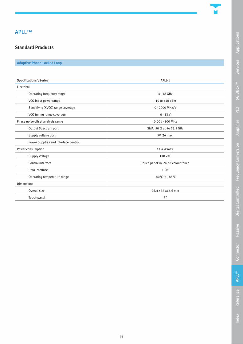
Standard Products
Adaptive Phase-Locked Loop
Specifications \ Series APLL-1
Electrical
Operating frequency range 4 - 18 GHz
VCO input power range -10 to +10 dBm
Sensitivity (KVCO) range coverage 0 - 2000 MHz/V
VCO tuning range coverage 0 - 13 V
Phase noise offset analysis range 0.001 - 100 MHz
Output Spectrum port SMA, 50 Ω up to 26.5 GHz
Supply voltage port 5V, 2A max.
Power Supplies and Interface Control
Power consumption 14.4 W max.
Supply Voltage 110 VAC
Control interface Touch panel w/ 24-bit colour touch
Data interface USB
Operating temperature range -40°C to +85°C
Dimensions
Overall size 26.4 x 37 x16.6 mm
Touch panel 7”
Inde
x
R
efer
ence
APL
LTM
Con
nect
or
P
assi
ve
D
igit
al C
ontr
olle
d
Fre
quen
cy C
onve
rsio
n
A
mpl
ifier
PLO
5G
BB
ox TM
Ser
vice
s
Ap
plic
atio
ns
36
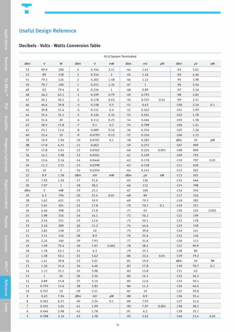
Useful Design Reference
Decibels - Volts - Watts Conversion Table
50 Ω System Terminated
dBm V W dBm V mW dBm mV µW dBm µV pW
53 99.9 200 4 0.354 2.51 -44 1.41 -93 5.01
52 89 158 3 0.316 2 -45 1.26 -94 4.46
51 79.3 126 2 0.282 1.58 -46 1.12 -95 3.98
50 70.7 100 1 0.251 1.26 -47 1 -96 3.54
49 63 79.4 0 0.224 1 -48 0.89 -97 3.16
48 56.2 63.1 -1 0.199 0.79 -49 0.793 -98 2.82
47 50.1 50.1 -2 0.178 0.63 -50 0.707 0.01 -99 2.51
46 44.6 39.8 -3 0.158 0.5 -51 0.63 -100 2.24 0.1
45 39.8 31.6 -4 0.141 0.4 -52 0.562 -101 1.99
44 35.4 25.1 -5 0.126 0.32 -53 0.501 -102 1.78
43 31.6 20 -6 0.112 0.25 -54 0.446 -103 1.58
42 28.2 15.8 -7 0.1 0.2 -55 0.398 -104 1.41
41 25.1 12.6 -8 0.089 0.16 -56 0.354 -105 1.26
40 22.4 10 -9 0.0793 0.13 -57 0.316 -106 1.12
39 19.9 7.94 -10 0.0707 0.1 -58 0.282 dBm nV pW
38 17.8 6.31 -11 0.063 -59 0.251 -107 999
37 15.8 5.01 -12 0.0562 -60 0.224 0.001 -108 890
36 14.1 3.98 -13 0.0501 -61 0.199 -109 793
35 12.6 3.16 -14 0.0446 -62 0.178 -110 707 0.01
34 11.2 2.51 -15 0.0398 -63 0.158 -111 630
33 10 2 -16 0.0354 -64 0.141 -112 562
32 8.9 1.58 dBm mV mW dBm µV nW -113 501
31 7.93 1.26 -17 31.6 -65 126 -114 446
30 7.07 1 -18 28.2 -66 112 -115 398
dBm V mW -19 25.1 -67 100 -116 354
29 6.3 794 -20 22.4 0.01 -68 89 -117 316
28 5.62 631 -21 19.9 -69 79.3 -118 282
27 5.01 501 -22 17.8 -70 70.7 0.1 -119 251
26 4.46 398 -23 15.8 -71 63 -120 224 0.001
25 3.98 316 -24 14.1 -72 56.2 -121 199
24 3.54 251 -25 12.6 -73 50.1 -122 178
23 3.16 200 -26 11.2 -74 44.6 -123 158
22 2.82 158 -27 10 -75 39.8 -124 141
21 2.51 126 -28 8.9 -76 35.4 -125 126
20 2.24 100 -29 7.93 -77 31.6 -126 112
19 1.99 79.4 -30 7.07 0.001 -78 28.2 -127 99.9
18 1.78 63.1 -31 6.3 -79 25.1 -128 89
17 1.58 50.1 -32 5.62 -80 22.4 0.01 -129 79.3
16 1.41 39.8 -33 5.01 -81 19.9 dBm nV fW
15 1.26 31.6 -34 4.46 -82 17.8 -130 70.7 0.1
14 1.12 25.1 -35 3.98 -83 15.8 -131 63
13 1 20 -36 3.54 -84 14.1 -132 56.2
12 0.89 15.8 -37 3.16 -85 12.6 -133 50.1
11 0.793 12.6 -38 2.82 -86 11.2 -134 44.6
10 0.707 10 -39 2.51 -87 10 -135 39.8
9 0.63 7.94 dBm mV µW -88 8.9 -136 35.4
8 0.562 6.31 -40 2.24 0.1 -89 7.93 -137 31.6
7 0.501 5.01 -41 1.99 -90 7.07 0.001 -138 28.2
6 0.446 3.98 -42 1.78 -91 6.3 -139 25.1
5 0.398 3.16 -43 1.58 -92 5.62 -140 22.4 0.01
Applications Services 5G
BB
ox TM PLO Am
plifier Freqency Conversion Digital Controlled Passive Connector APLL
TM Reference Index

37
Return Loss (dB) VSWR Return Loss
(dB) VSWR Return Loss (dB) VSWR Return Loss
(dB) VSWR Return Loss (dB) VSWR
46.064 1.01 13.842 1.51 9.485 2.01 7.327 2.51 5.999 3.01
40.086 1.02 13.708 1.52 9.428 2.02 7.294 2.52 5.977 3.02
36.607 1.03 13.577 1.53 9.372 2.03 7.262 2.53 5.956 3.03
34.151 1.04 13.449 1.54 9.317 2.04 7.23 2.54 5.935 3.04
32.256 1.05 13.324 1.55 9.262 2.05 7.198 2.55 5.914 3.05
30.714 1.06 13.201 1.56 9.208 2.06 7.167 2.56 5.893 3.06
29.417 1.07 13.081 1.57 9.155 2.07 7.135 2.57 5.872 3.07
28.299 1.08 12.964 1.58 9.103 2.08 7.105 2.58 5.852 3.08
27.318 1.09 12.849 1.59 9.051 2.09 7.074 2.59 5.832 3.09
26.444 1.1 12.736 1.6 8.999 2.1 7.044 2.6 5.811 3.1
25.658 1.11 12.626 1.61 8.949 2.11 7.014 2.61 5.791 3.11
24.943 1.12 12.518 1.62 8.899 2.12 6.984 2.62 5.771 3.12
24.289 1.13 12.412 1.63 8.849 2.13 6.954 2.63 5.751 3.13
23.686 1.14 12.308 1.64 8.8 2.14 6.925 2.64 5.732 3.14
23.127 1.15 12.207 1.65 8.752 2.15 6.896 2.65 5.712 3.15
22.607 1.16 12.107 1.66 8.705 2.16 6.867 2.66 5.693 3.16
22.12 1.17 12.009 1.67 8.657 2.17 6.839 2.67 5.674 3.17
21.664 1.18 11.913 1.68 8.611 2.18 6.811 2.68 5.654 3.18
21.234 1.19 11.818 1.69 8.565 2.19 6.783 2.69 5.635 3.19
20.828 1.2 11.725 1.7 8.519 2.2 6.755 2.7 5.617 3.2
20.443 1.21 11.634 1.71 8.474 2.21 6.728 2.71 5.598 3.21
20.079 1.22 11.545 1.72 8.43 2.22 6.7 2.72 5.579 3.22
19.732 1.23 11.457 1.73 8.386 2.23 6.673 2.73 5.561 3.23
19.401 1.24 11.37 1.74 8.342 2.24 6.646 2.74 5.542 3.24
19.085 1.25 11.285 1.75 8.299 2.25 6.62 2.75 5.524 3.25
18.783 1.26 11.202 1.76 8.257 2.26 6.594 2.76 5.506 3.26
18.493 1.27 11.12 1.77 8.215 2.27 6.567 2.77 5.488 3.27
18.216 1.28 11.039 1.78 8.173 2.28 6.541 2.78 5.47 3.28
17.949 1.29 10.96 1.79 8.132 2.29 6.516 2.79 5.452 3.29
17.692 1.3 10.881 1.8 8.091 2.3 6.49 2.8 5.435 3.3
17.445 1.31 10.804 1.81 8.051 2.31 6.465 2.81 5.417 3.31
17.207 1.32 10.729 1.82 8.011 2.32 6.44 2.82 5.4 3.32
16.977 1.33 10.654 1.83 7.972 2.33 6.415 2.83 5.383 3.33
16.755 1.34 10.581 1.84 7.933 2.34 6.39 2.84 5.365 3.34
16.54 1.35 10.509 1.85 7.894 2.35 6.366 2.85 5.348 3.35
16.332 1.36 10.437 1.86 7.856 2.36 6.341 2.86 5.331 3.36
16.131 1.37 10.367 1.87 7.818 2.37 6.317 2.87 5.315 3.37
15.936 1.38 10.298 1.88 7.781 2.38 6.293 2.88 5.298 3.38
15.747 1.39 10.23 1.89 7.744 2.39 6.27 2.89 5.281 3.39
15.563 1.4 10.163 1.9 7.707 2.4 6.246 2.9 5.265 3.4
15.385 1.41 10.097 1.91 7.671 2.41 6.223 2.91 5.248 3.41
15.211 1.42 10.032 1.92 7.635 2.42 6.2 2.92 5.232 3.42
15.043 1.43 9.968 1.93 7.599 2.43 6.177 2.93 5.216 3.43
14.879 1.44 9.904 1.94 7.564 2.44 6.154 2.94 5.2 3.44
14.719 1.45 9.842 1.95 7.529 2.45 6.131 2.95 5.184 3.45
14.564 1.46 9.78 1.96 7.494 2.46 6.109 2.96 5.168 3.46
14.412 1.47 9.72 1.97 7.46 2.47 6.086 2.97 5.152 3.47
14.264 1.48 9.66 1.98 7.426 2.48 6.064 2.98 5.137 3.48
14.12 1.49 9.601 1.99 7.393 2.49 6.042 2.99 5.121 3.49
13.979 1.5 9.542 2 7.36 2.5 6.021 3 5.105 3.5
Useful Design Reference
Return Loss Vs. VSWR Table
Inde
x
R
efer
ence
APL
LTM
Con
nect
or
P
assi
ve
D
igit
al C
ontr
olle
d
Fre
quen
cy C
onve
rsio
n
A
mpl
ifier
PLO
5G
BB
ox TM
Ser
vice
s
Ap
plic
atio
ns
38
APLL-1 APLL™ 35
BB-ANT-28-1x1 BBox™ 14
BB-ANT-28-2x2 BBox™ 14
BB-ANT-28-4x4 BBox™ 14
BB-ANT-28-8x8 BBox™ 14
BB-CH BBox™ 14
BB-PHA-ID-28-04/08/16 BBox™ 14
BB-SW-SP4T-0050 BBox™ 14
BB-UDC-0006 BBox™ 14
BB-UDC-0612 BBox™ 14
BL-RRC-1116 Passives 28
BT-NO-0024-30 Passives 28
BT-NO-0034-30 Passives 28
BT-TM-0040-50 Passives 28
BT-TM-0050-50 Passives 28
DCA-NC-000300-06-005315 Digital Controlled 26
DCB-TM-0026-50 Passives 28
DCB-TM-0040-50 Passives 28
DCB-TM-0050-50 Passives 28
DCF-BPF-B1-00220042-5-C Digital Controlled 26
DCF-BPF-B1-00430089-5-C Digital Controlled 26
DCF-BPF-B1-00630140-5-C Digital Controlled 26
DCF-BPF-B3-06001800-9-C Digital Controlled 26
DCF-HPF-B3-06001000-4-C Digital Controlled 26
DCF-LPF-B3-09001800-5-C Digital Controlled 26
DPS-PO-02650305-C Digital Controlled 26
DSW-NC-SP4T-0050 Digital Controlled 26
DSW-NC-SP8T-0050 Digital Controlled 26
DSW-NC-SPDT-0050 Digital Controlled 26
DSW-QU-M-0018-2x2 Digital Controlled 26
DSW-QU-M-0018-2x2-S Digital Controlled 26
DSW-QU-M-0018-4x4 Digital Controlled 26
FM-NC-075112-04 Freq. Conversion 23
FM-NC-075225-02 Freq. Conversion 23
FT-BPF-0408-C Passives 28
FT-BPF-3547-C Passives 28
FT-BPF-4053-C Passives 28
LNA-NC-1630-21 Amplifiers 21
LNA-NC-2040-20 Amplifiers 21
MC DIP Connector Connectors 31
MC SMT Connector Connectors 31
MX-KA-L-2729-0608-21 Freq. Conversion 23
MX-KA-L-2729-0911-18 Freq. Conversion 23
MX-KA-L-3739-0911-28 Freq. Conversion 23
MX-KA-L-D-2838-0911-1828 Freq. Conversion 23
MX-NO-100440-000140 Freq. Conversion 23
MX-NO-110400-000120 Freq. Conversion 23
MX-VO-710860-000120 Freq. Conversion 23
NT CMM Connectors 33
NT DMM Connectors 33
PA-NC-0040-31 Amplifiers 21
PA-NC-0218-34 Amplifiers 21
PA-NC-1630-42 Amplifiers 21
PLO-MFSO-B1-S/E/C Oscillators 17
PLO-MFSO-B2-C Oscillators 17
PLO-MFSO-B3-C Oscillators 17
PLO-SFSO-B1-S/E/C Oscillators 17
PLO-SFSO-B2-C Oscillators 17
PLO-SFSO-B3-C Oscillators 17
Part No. Category Page No.
Index
Part No. Category Page No.
Applications Services 5G
BB
ox TM PLO Am
plifier Freqency Conversion Digital Controlled Passive Connector APLL
TM Reference Index
For more information, please contact us:
Taiwan Office
Hedy Chuang [email protected] +886-2-82269168 #892
China Office
Alex Chen [email protected] +15190171508 wechat: alexchen-faith
Worldwide Resellers
www.tmytek.com/about/resellers/


![[13] b-and-bb](https://img.pdfslide.us/doc/110x75/55cf8ce75503462b139065bd/13-b-and-bb.jpg)