Embed Size (px)
Citation preview
1
PT
P and P
MP
LinksP
TP
and PM
P Links
RF
Links Overview

2
Full D
uplex Com
munications
Full D
uplex Com
munications
ÿ ÿT
wo stations can talk and listen to each other at the sam
eT
wo stations can talk and listen to each other at the sam
etim
e.tim
e.
ÿ ÿT
his requires two separate m
edia.T
his requires two separate m
edia.
ÿ ÿIn the case of a w
ireless link, 2 separate channels areIn the case of a w
ireless link, 2 separate channels arerequired. T
his is referred to as Frequency D
ivision Duplex
required. This is referred to as F
requency Division D
uplex(F
DD
)(F
DD
)Station 1Station 2
Channel 1
Channel 2
TX
RX
TX
RX

3
Half D
uplex Com
munications
Half D
uplex Com
munications
ÿ ÿT
wo stations have to take turns talking and listening.
Tw
o stations have to take turns talking and listening.S
imultaneous com
munications is not possible. R
equiresS
imultaneous com
munications is not possible. R
equireshandshaking.handshaking.
ÿ ÿT
wo stations share a com
mon m
ediaT
wo stations share a com
mon m
edia
ÿ ÿT
his is referred to as time division duplex (T
DD
)T
his is referred to as time division duplex (T
DD
)
Station 1Station 2
Channel 1
TX
RX
TX
RX

4
Advantages of F
DD
Advantages of F
DD
ÿ ÿM
ore efficient data transfer due to lower overhead
More efficient data transfer due to low
er overhead(required for handshaking).(required for handshaking).
ÿ ÿM
ore efficient use of spectrum in high traffic system
sM
ore efficient use of spectrum in high traffic system
s
ÿ ÿM
ost ITU
frequency bands are structured for FD
D.
Most IT
U frequency bands are structured for F
DD
.
ÿ ÿH
alf the data rate for equivalent data transfer as TD
D.
Half the data rate for equivalent data transfer as T
DD
.
ÿ ÿD
oes not have latency issues associated with
Does not have latency issues associated w
ithhandshaking.handshaking.

5
Advantages of T
DD
Advantages of T
DD
ÿ ÿE
asier to coordinate channels than FD
D.
Easier to coordinate channels than F
DD
.
ÿ ÿR
F H
ardware is potentially less com
plicated and thusR
F H
ardware is potentially less com
plicated and thuslow
er cost.low
er cost.
ÿ ÿInstallation m
ay be simpler.
Installation may be sim
pler.
ÿ ÿO
nly one antenna per T/R
Only one antenna per T
/R
ÿ ÿIn low
traffic networks the spectrum
is utilized more
In low traffic netw
orks the spectrum is utilized m
oreefficiently.efficiently.

6
Point to P
oint (PT
P) Links
Point to P
oint (PT
P) Links
ÿ ÿA
point to point link is one station comm
unicating with
A point to point link is one station com
municating w
ithanother station, 1 to 1.another station, 1 to 1.
ÿ ÿB
oth stations are usually similar in data-rate, m
odulationB
oth stations are usually similar in data-rate, m
odulationand overhead form
at.and overhead form
at.
ÿ ÿF
DD
PT
P links do not require m
edia access control which
FD
D P
TP
links do not require media access control w
hichreduces overhead.reduces overhead.

7
Point to P
oint (PT
P) Links
Point to P
oint (PT
P) Links
ÿ ÿF
DD
PT
P links do not require handshaking, this
FD
D P
TP
links do not require handshaking, thism
inimizes latency.
minim
izes latency.
ÿ ÿP
TP
links are usually used in constant bit rateP
TP
links are usually used in constant bit rateapplications, such as synchronous data transport andapplications, such as synchronous data transport andtrunkingtrunking
applications. applications.
ÿ ÿP
TP
links can be built with extra m
argin to deal with fades
PT
P links can be built w
ith extra margin to deal w
ith fadesand other im
pairments.
and other impairm
ents.

8
System
Pow
er LevelsS
ystem P
ower Levels
ÿ ÿP
oint to point link has extra system gain to increase
Point to point link has extra system
gain to increaseavailability.availability.
ÿ ÿLow
probability of interference to or from other stations.
Low probability of interference to or from
other stations.
ÿ ÿP
to P links typically have narrow
beam antennas.
P to P
links typically have narrow beam
antennas.

9
System
Pow
er Levels PT
P Links
System
Pow
er Levels PT
P Links
Station 1Station 2
TX
= +
18 dBm
Antenna G
ain 30 dBA
ntenna Gain 30 dB
RX
= -42 dBm
RX
Threshold = -72 dB
m
Path loss = -116 dB

10
Point to M
ultipoint (PM
P) Links
Point to M
ultipoint (PM
P) Links
ÿ ÿO
ne base station comm
unicating with m
ore than oneO
ne base station comm
unicating with m
ore than onesubscriber on shared m
edia.subscriber on shared m
edia.
PRIZ
M 2400
11
Point to M
ultipoint (PM
P) Links
Point to M
ultipoint (PM
P) Links
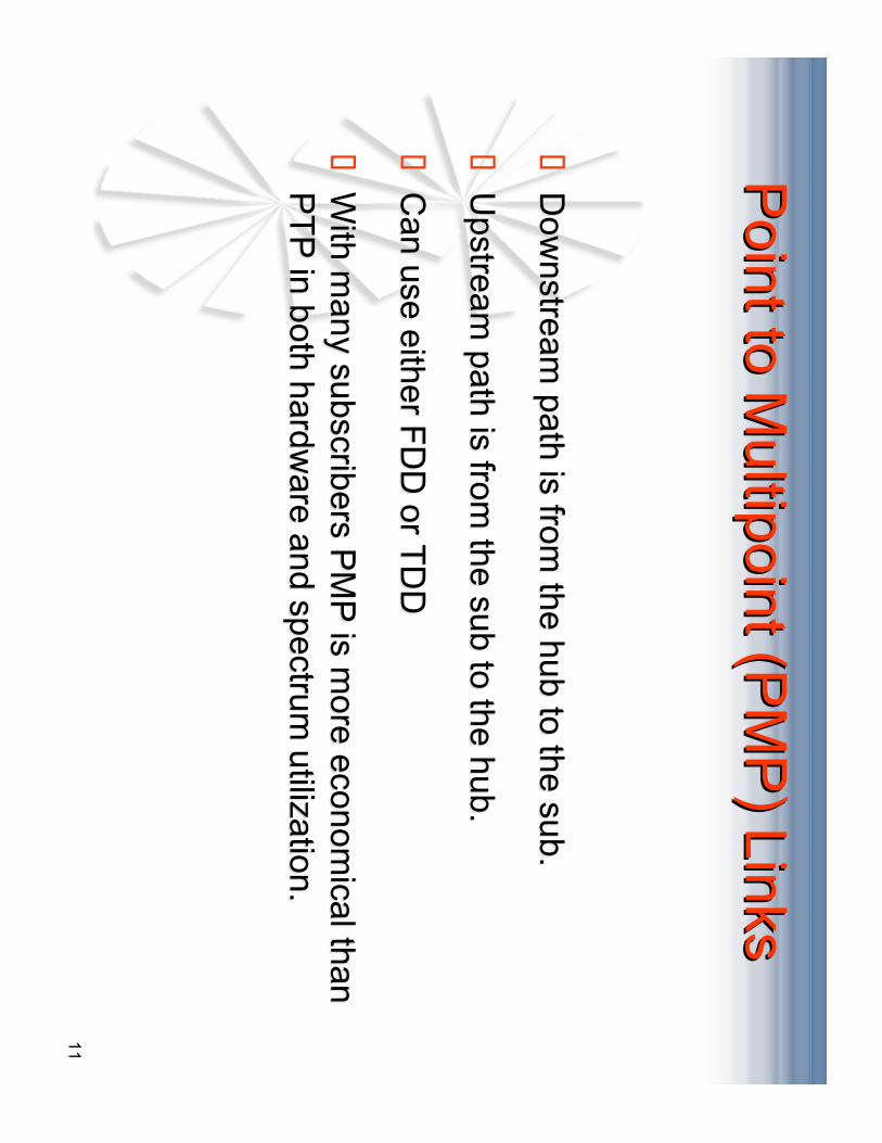
ÿ ÿD
ownstream
path is from the hub to the sub.
Dow
nstream path is from
the hub to the sub.
ÿ ÿU
pstream path is from
the sub to the hub.U
pstream path is from
the sub to the hub.
ÿ ÿC
an use either FD
D or T
DD
Can use either F
DD
or TD
D
ÿ ÿW
ith many subscribers P
MP
is more econom
ical thanW
ith many subscribers P
MP
is more econom
ical thanP
TP
in both hardware and spectrum
utilization.P
TP
in both hardware and spectrum
utilization.

12
Point to M
ultipoint (PM
P) Links
Point to M
ultipoint (PM
P) Links
ÿ ÿD
ata-rates and modulation tend to be asym
metrical to
Data-rates and m
odulation tend to be asymm
etrical toreflect the the asym
metric flow
of data in this type ofreflect the the asym
metric flow
of data in this type ofsystem
.system
.
ÿ ÿM
edia Access C
ontrol (MA
C) is m
andatory for a PM
PM
edia Access C
ontrol (MA
C) is m
andatory for a PM
Psystem
.system
.
ÿ ÿT
ypically IP based, does not w
ork well for constant bit rate
Typically IP
based, does not work w
ell for constant bit rateapplications.applications.

13
System
Pow
er Levels PM
P Links
System
Pow
er Levels PM
P Links
ÿ ÿIn a point to m
ulti-point system pow
er levels must be
In a point to multi-point system
power levels m
ust becontrolled to prevent self interference.controlled to prevent self interference.
ÿT
he H
ub
TX
has a fixed
ou
tpu
t po
wer.
ÿT
he H
ub
RX
has a fixed
gain
.
ÿT
he S
ub
TX
has a variab
le ou
tpu
t po
wer th
at is con
trolled
by
the R
SL
at the H
ub
RX
.
ÿT
he S
ub
RX
will ad
just its g
ain fo
r pro
per R
SL
.

14
System
Pow
er Level PM
P Links
System
Pow
er Level PM
P Links
HU
B
TX
Pw
r = +18 dBm
RSL
= -72 dB
m
Ant. G
ain = 20 dBi
TX
Pw
r = +6 dBm
RSL
= -60 dB
m
Ant. G
ain = 20 dBiTX
Pw
r = +12 dBm
RSL
= -66 dB
m
Ant. G
ain = 20 dBi
TX
Pw
r = +18 dBm
RSL
= -72 dB
m
Ant. G
ain = 20 dBi
Sub 3
Sub 2
Sub 1
Path loss = -130 dB
Path loss = -124 dB
Path loss = -118 dB

15
System
Pow
er Levels PM
P Links
System
Pow
er Levels PM
P Links
ÿ ÿIf an unlim
ited number of channels are available then self
If an unlimited num
ber of channels are available then selfinterference is not a consideration.interference is not a consideration.
ÿ ÿW
ithin a sector subscribers will not interfere w
ith eachW
ithin a sector subscribers will not interfere w
ith eachother due to T
DM
A.
other due to TD
MA
.
ÿ ÿB
etween S
ectors of the same channel interference can
Betw
een Sectors of the sam
e channel interference canoccur, T
DM
A control no longer applies.
occur, TD
MA
control no longer applies.
ÿ ÿC
o-channel interference occurs due to antenna sideC
o-channel interference occurs due to antenna sidelobes, back lobes, im
properly aimed antennas and
lobes, back lobes, improperly aim
ed antennas andreflections.reflections.

16
System
Pow
er Levels PM
P Links
System
Pow
er Levels PM
P Links
ÿ ÿT
o minim
ize self interference...T
o minim
ize self interference...
ÿU
se min
imu
m n
ecessary hu
b T
X p
ow
er to reach
farthest o
ut
sub
scriber.
ÿK
eep farth
est ou
t sub
scribers in
center o
f beam
if po
ssible.
ÿC
arefully ad
just elevatio
n an
gle to
give g
oo
d sig
nal to
farthest o
ut su
bscrib
ers wh
ile still pro
vidin
g u
seable sig
nal
to clo
se in S
ub
s.
ÿM
ake sure S
ub
anten
nas are p
oin
ted co
rrectly, use elevatio
nb
rackets if necessary.
ÿU
se maxim
um
nu
mb
er of ch
ann
els that is p
ractical.
ÿA
ll links sh
ou
ld b
e LO
S, avo
id reflectio
ns an
d o
bstru
ction
s.
17
Media A
ccess Control
Media A
ccess Control
ÿ ÿT
he M
AC
is imp
lemen
ted b
y the h
ub
mo
dem
and
con
trols
Th
e MA
C is im
plem
ented
by th
e hu
b m
od
em an
d co
ntro
lsaccess o
f the su
bscrib
er mo
dem
s to th
e shared
chan
nel. S
pike
access of th
e sub
scriber m
od
ems to
the sh
ared ch
ann
el. Sp
ikeu
ses the D
OC
SIS
(IEE
E 802.14) M
AC
.u
ses the D
OC
SIS
(IEE
E 802.14) M
AC
.
ÿ ÿE
ach S
ub
scriber is assig
ned
on
e or m
ore exclu
sive time slo
ts inE
ach S
ub
scriber is assig
ned
on
e or m
ore exclu
sive time slo
ts inw
hich
they m
ay transm
it data. T
his is referred
to as tim
e do
main
wh
ich th
ey may tran
smit d
ata. Th
is is referred to
as time d
om
ainm
ultip
le access (TD
MA
).m
ultip
le access (TD
MA
).
ÿ ÿT
he H
ub
mo
dem
adju
sts the p
ow
er level of th
e Su
b T
X.
Th
e Hu
b m
od
em ad
justs th
e po
wer level o
f the S
ub
TX
.
ÿ ÿT
he H
ub
mo
dem
synch
ron
izes all sub
s with
the H
ub
and
Th
e Hu
b m
od
em syn
chro
nizes all su
bs w
ith th
e Hu
b an
deq
ualizes p
ath d
elay.eq
ualizes p
ath d
elay.

18
Media A
ccess Control
Media A
ccess Control
ÿ ÿT
he MA
C provides a m
eans for new subscribers to join
The M
AC
provides a means for new
subscribers to jointhe netw
ork.the netw
ork.
ÿ ÿT
he MA
C also provides for equitable sharing of bandw
idthT
he MA
C also provides for equitable sharing of bandw
idthand arbitrating contention am
ong subscribers.and arbitrating contention am
ong subscribers.
ÿ ÿT
he MA
C m
ust assure that all similarly provisioned
The M
AC
must assure that all sim
ilarly provisionedsubscribers have sim
ilar quality of service regardless ofsubscribers have sim
ilar quality of service regardless oftheir location.their location.

19
Bro
adband W
irele
ss E
xam
ple
Bro
adband W
irele
ss E
xam
ple
q qT
ransceiverT
ransceiver
q qM
odulation Techniques
Modulation T
echniques
q qP
ath Analysis
Path A
nalysis
q qA
mplifier P
arameters
Am
plifier Param
eters
q qF
ilter Types
Filter T
ypes
q qF
ilter Technologies
Filter T
echnologies
q qP
LL and Attenuators
PLL and A
ttenuators

20
Tra
nsceiv
er D
esig
n O
utlin
eT
ransceiv
er D
esig
n O
utlin
e
qO
verview
qF
un
ction
ality
qV
ersion
s
qD
esign
Featu
res
qB
asic RF
Co
ncep
ts

21
Key R
F P
ara
mete
rs fo
r Wire
less
Key R
F P
ara
mete
rs fo
r Wire
less
Syste
ms
Syste
ms
•A
ntenna•
Gain
•Sidelobe L
evel
•T
ransceiver•
Frequency Accuracy
•Spurious R
esponse (Regulatory A
gency)•
RM
S Phase Error
•O
utput Power
•M
odem•
Data rates
•R
equired Signal to Noise
•Spurious R
esponse (Regulatory A
gency)

22
(0000) (0001) (0010) (0000) (0001) (0010)
(0011) (0011)
(0100) (0101) (0110) (0111)(0100) (0101) (0110) (0111)
(1000) (1001) (1010) (1011)(1000) (1001) (1010) (1011)
(1100) (1101) (1110) (1100) (1101) (1110) (1111)
(1111)
(00) (00)
(01) (10)(01) (10)
(11)
(11)
Modula
tion T
echniq
ues
Modula
tion T
echniq
ues
BP
SK
QP
SK
16QA
M
(0) (1)(0) (1)

23
Modula
tion W
ith N
ois
eM
odula
tion W
ith N
ois
e
BP
SK
QP
SK
16QA
M
24
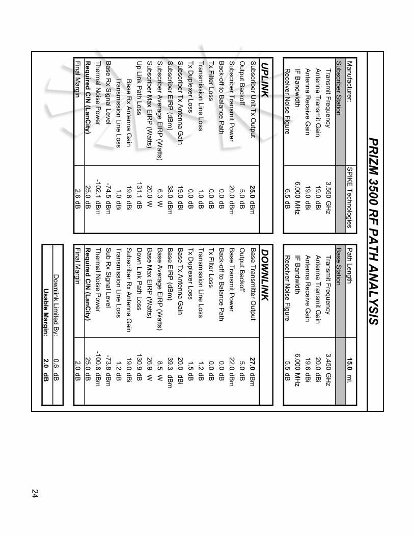
Manufacturer:
SP
IKE
Technologies
Path Length
15.0 m
i.
Subscriber S
tation B
ase Station
Transm
it Frequency
3.550G
Hz
Transm
it Frequency
3.450G
Hz
Antenna T
ransmit G
ain19.0
dBi
Antenna T
ransmit G
ain20.0
dBi
Antenna R
eceive Gain
19.0dB
i A
ntenna Receive G
ain19.6
dBi
IF B
andwidth
6.000M
Hz
IF B
andwidth
6.000M
Hz
Receiver N
oise Figure
6.5dB
Receiver N
oise Figure
5.5dB
UP
LIN
K D
OW
NL
INK
Subscriber U
nit Tx O
utput25.0
dBm
Base T
ransmitter O
utput27.0
dBm
Output B
ackoff5.0
dB O
utput Backoff
5.0dB
Subscriber T
ransmit P
ower
20.0dB
m B
ase Transm
it Pow
er22.0
dBm
Back-off to B
alance Path
0.0dB
Back-off to B
alance Path
0.0dB
Tx F
ilter Loss0.0
dB T
x Filter Loss
0.0dB
Transm
ission Line Loss1.0
dB T
ransmission Line Loss
1.2dB
Tx D
uplexer Loss0.0
dB T
x Duplexer Loss
1.5dB
Subscriber T
x Antenna G
ain19.0
dBi
Base T
x Antenna G
ain20.0
dBi
Subscriber E
IRP
(dBm
)38.0
dBm
Base E
IRP
(dBm
)39.3
dBm
Subscriber A
verage EIR
P (W
atts)6.3
W B
ase Average E
IRP
(Watts)
8.5 W
Subscriber M
ax EIR
P (W
atts)20.0
W B
ase Max E
IRP
(Watts)
26.9 W
Up Link P
ath Loss131.1
dB D
own Link P
ath Loss130.9
dB
Base R
x Antenna G
ain19.6
dBi
Subscriber R
x Antenna G
ain19.0
dBi
Transm
ission Line Loss1.0
dBi
Transm
ission Line Loss1.2
dB
Base R
x Signal Level
-74.5dB
m S
ub Rx S
ignal Level-73.8
dBm
Therm
al Noise P
ower
-102.1dB
m T
hermal N
oise Pow
er-100.8
dBm
Req
uired
C/N
(Lan
City)
25.0dB
Req
uired
C/N
(Lan
City)
25.0dB
Final M
argin2.6
dB F
inal Margin
2.0dB
Dow
nlink Limited B
y:0.6
dB
Usab
le Marg
in:
2.0d
B
PR
IZM
3500 RF
PA
TH
AN
AL
YS
IS

25
Receive
LN
AG
ain
10 MH
zR
eferenceO
scillator
IF
Transm
it
BPF
SAW
SP
A
LD
1
Analog
Atten
Gain
BPF
Ceram
ic
Analog
Atten
Transceiver Block DiagramTransceiver Block Diagram
Digital
Atten
Digital
Atten
PLL
#1
PLL
#2
External
Reference
BPF
Helical
Gain
BPF
Ceram
ic
MC
U &
Control
Loop
Loop
Loop
Loop
BPF
Ceram
icB
PFC
eramic
DUPLEXER
Res.
Coup.
RSSI

26
Am
plifie
rs - C
ritical P
ara
mete
rsA
mplifie
rs - C
ritical P
ara
mete
rs
•G
ain / S
tability
•L
inearity / O
utp
ut 3rd
Ord
er Intercep
tP
oin
t ( OIP
3 )
•O
utp
ut P
ow
er / 1dB
Co
mp
ression
Po
int
qN
oise F
igu
re

27
“ “Ideal
Ideal” ” A
mplifie
r Gain
Am
plifie
r Gain
Linear Gain Amplifier
1 10 100
1000
10000
100000
0.010.1
110
1001000
Pin (milliwatts)
Pout (milliwatts)
Linear Gain Amplifier
0 10 20 30 40 50 60
-30-20
-100
1020
3040
Pin (dBm)
Pout (dBm)

28
Actu
al A
mplifie
r Perfo
rmance
Actu
al A
mplifie
r Perfo
rmance
F1 F
22515.0 2515.1
F1-D
2514.9
Frequency (M
Hz)
F1
+D
2515.2F
2-F
10.1
F2
+F
15030.2

29
Mixers
Mixers
•M
ixers are the key component for F
requency Conversion
•C
an be used for either Up or D
own C
onversion
•T
he output response is actually: N L
O +
M R
F
RF
IN
Radio F
requency ( RF
)
IF IN
( IF ) Interm
ediate Frequency = L
O + R
F
X35.75 M
Hz
LO IN
384.25 MH
zL
ocal Oscillator
420 MH
z( 360 M
Hz )

30
Filte
r Types
Filte
r Types
Amplitude
fo
Frequency
qB
and
Pass
qL
ow
Pass
qH
igh
Pass
qB
and
Sto
p
qD
iplexer

31
Filte
r Technolo
gie
sFilte
r Technolo
gie
s
Type
Advantages
Disadvantages
- Lum
ped Elem
entSm
all size, Low
costL
ow F
req Lim
it
- Microstrip/Stripline
Planar, H
igh Repeatability
Large in Size
- Ceram
icSm
all size, Low
Cost
Low
Freq L
imit
- Cavity
High Q
High C
ost, Large
- SAW
High R
ejection "in Close"
High L
oss ( Surface A
coustic Wave )
32
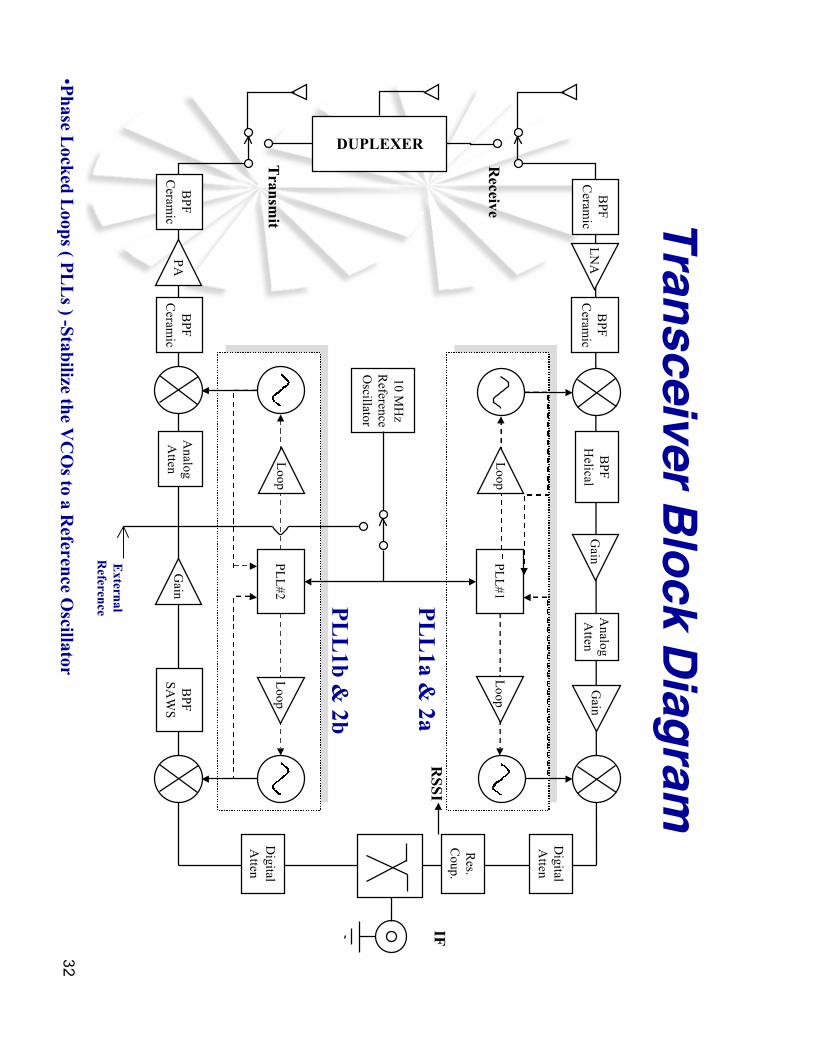
Transceiver Block Diagram
Receive
Receive
LN
AG
ain
10 MH
zR
eferenceO
scillator
IF IF
Transm
itT
ransmit
BPF
SAW
SP
A
Analog
Atten
Gain
BPF
Ceram
ic
Analog
Atten
Digital
Atten
Digital
Atten
PLL
#1
PLL
#2
External
External
Reference
Reference
BPF
Helical
Gain
BPF
Ceram
ic
Loop
Loop
Loop
Loop
BPF
Ceram
icB
PFC
eramic
DUPLEXER
Res.
Coup.
RSSI
PL
L1a &
2a
PL
L1b &
2b
•Phase L
ocked Loops ( P
LL
s ) -Stabilize the VC
Os to a R
eference Oscillator
33
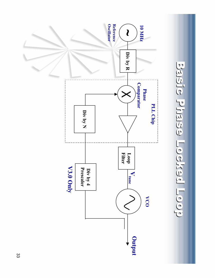
Basic
Phase L
ocked L
oop
Basic
Phase L
ocked L
oop
XL
oopF
ilter
Vtune
Output
Div by N
Div by R
~Reference
Oscillator
10 MH
zP
hase C
omparator
V3.0 O
nly
Div by 4
Prescaler
PL
L C
hipV
CO
34
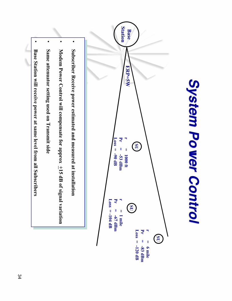
Base
Station
SU
r = 1000 ft
Pr =
-53 dBm
Loss =
-90 dB
SU
r = 1 m
ileP
r = -67 dB
mL
oss = -104 dB
SU
r = 6 m
ileP
r = -83 dB
mL
oss = -120 dB
ER
P=5W
•Subscriber R
eceive power estim
ated and measured at installation
•M
odem P
ower C
ontrol will com
pensate for approx +15 dB
of signal variation
•Sam
e attenuator setting used on Transm
it side
•B
ase Station will receive pow
er at same level from
all Subscribers
•Subscriber R
eceive power estim
ated and measured at installation
•M
odem P
ower C
ontrol will com
pensate for approx +15 dB
of signal variation
•Sam
e attenuator setting used on Transm
it side
•B
ase Station will receive pow
er at same level from
all Subscribers
System Pow
er ControlSystem
Power Control

35
•Digital A
ttenuators
•C
oarse gain selection
•Step Size / 2dB
•Analog A
ttenuators
•Fine Step Size / < .1 dB
•Fine gain selection and tem
peraturecom
pensation
Varia
ble
Atte
nuato
rsV
aria
ble
Atte
nuato
rs


![RFID Tutorial [3].ppt [Read-Only] - Aalborg Universitetkom.aau.dk/~pe/education/literature/9sem/rfid-tutorial3.pdf · Linear Vs Circular polarized dBi vs dBd ... – For dBm the units](https://img.pdfslide.us/doc/110x75/5aada4c77f8b9adb688b533f/rfid-tutorial-3ppt-read-only-aalborg-peeducationliterature9semrfid-tutorial3pdflinear.jpg)