Embed Size (px)
Citation preview
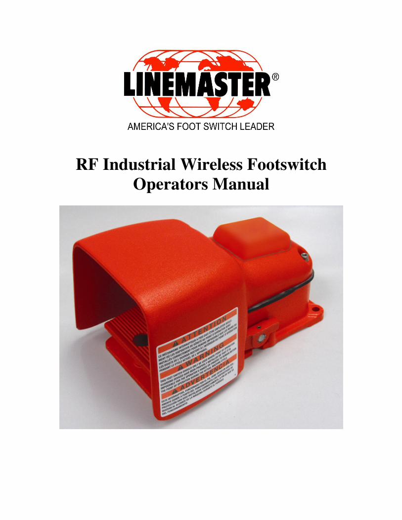
RF Industrial Wireless Footswitch
Operators Manual
Manual P/N 907-EE Rev A
2 of 18
GUARANTEE
All wireless footswitches sold by Linemaster Switch Corporation are fully guaranteed as
to materials and workmanship for a period of 1 year. Linemaster Switch reserves the right
to perform guarantee service operations in its own factory, at an authorized repair station,
or in the customer’s installation.
Our obligation under this guarantee is limited to repairing or, at our option, replacing any
defective parts of our equipment, except fuses or batteries, without charge, if defects
occur in normal service.
Claims for damage in shipment should be filed promptly with the transportation
company. All correspondence covering the instrument should specify the model and
serial number.
Linemaster Switch Corporation will make available on request such circuit diagrams,
component drawings, component parts lists, descriptions, calibration instructions, or
other information, which will assist the users or appropriately qualified technical
personnel to repair those parts of the equipment which are classified by Linemaster
Switch as repairable.
Tel: (860) 974-1000
Fax: ( 860) 974-0691
Fax: ( 800) 974-3668 U.S.A. Only
www.linemaster.com
Manual P/N 907-EE Rev A
3 of 18
Safety
The information presented in this section is important for the safety of the operator and
also serves to enhance equipment reliability. This section describes how the terms
Warning, Caution, Important, and Note are used throughout the manual. In addition,
Linemasters’ standard equipment symbols are defined.
General Information
General Use
If the foot switch is cold to the touch or below ambient temperature, allow
it to stabilize before use.
Periodically, whenever the integrity of the switch is in doubt, test all
functions.
The Hercules wireless footswitch has not been evaluated as functional
safety devices for protection of humans or equipment."
Responsibility of the manufacturer
Linemaster Switch is responsible for the effects on safety, reliability, and
performance if:
• Assembly operations, extensions, readjustments, modifications, or
repairs are carried out by persons authorized by Linemaster Switch
Corporation.
• The switch is used in accordance with the instructions for use.
• IT IS THE RESPONSIBILITY OF THE USER to determine the
suitability of a foot control for the user’s intended use and to determine
that the foot control chosen by the user and wiring up and installation of
the same will comply with all Federal, State and Local safety and health
regulations and codes.
Manual P/N 907-EE Rev A
4 of 18
Definitions of Terminology
Four types of special notice are used throughout this manual. They are: Warning,
Caution, Important, and Note. The warnings and cautions in this safety section
relate to the equipment in general and apply to all aspects of the foot switch. Be
sure to read the other chapters because there are additional warnings and cautions,
which relate to specific features of the footswitch.
Warning- A WARNING indicates a potentially hazardous situation,
which, if not avoided, could result in death or serious
injury.
Caution- A CAUTION indicates a potentially hazardous situation,
which, if not avoided, may result in minor or moderate
injury. Cautions are also used to avoid damage to
equipment.
Important- An IMPORTANT notice indicates an emphasized note. It
is something you should be particularly aware of,
something not readily apparent.
Note- A NOTE indicates a particular point of information,
something on which to focus your attention.
Warnings To avoid personal injury, do not use this switch on
machinery with an unguarded point of operation.
Use of foot controls on machinery lacking effective point
of operation safeguards can cause serious injury to the
operator. Foot controls should only be used where “Point of Operation”
and “Pinch Point” guarding devices have been properly
installed and are utilized so that it is IMPOSSIBLE for the
operator’s hands or fingers to remain within the point of
operation during the machine cycle.
Manual P/N 907-EE Rev A
5 of 18
Warnings
Accidental spills- In the event that fluids are accidentally spilled on the
receiver, take the receiver out of operation and inspect for
damage.
Electric shock- To reduce the risk of electrical shock do not remove any
covers. Refer servicing to qualified personnel
Explosion hazard- Do not use this equipment in the presence of flammable
materials.
Grounding- Do not defeat the three-wire grounding feature of the AC
adapter. A dangerous shock hazard may result.
Interfacing to equipment- Foot switches must be interfaced with other equipment.
Be certain to consult manufacturer’s specifications to
maintain safe operation.
Cautions:
Annual servicing- For continued safety and performance of the switch, it is
recommended that the functionality and electrical safety
of the switch be verified on an annual basis by an
authorized Linemaster representative.
Daily testing- It is essential that the foot switch be inspected everyday or
before use.
Performance- The RF wireless footswitch system operates on a
frequency range of 2.405-2.480 GHz. It should be tested
to assure compatibility with any device it is connected to
or environment it is working in.
Report all problems experienced with the footswitch. If
the footswitch is not working properly, contact your
service representative for service. The footswitch should
not be used if it is not working properly.
On a REGULAR BASIS, lubricate the treadle pivot rod
with one or two drops of lubricating oil on that portion of
the pivot rod that extends between the outside of the base
and inside of the treadle; two places.
Manual P/N 907-EE Rev A
6 of 18
Cautions:
Changes or modifications not expressly approved by
Linemaster Switch Corporation could void the user’s
authority to operate the equipment.
Important: Performance-
Multiple transmitters and receivers may be operated in a
single room.
Each transmitter and receiver is paired at the factory.
Loss of signal- If the receiver does not receive a signal from the
transmitter for a period of 525ms it will shut off the
outputs. However, once the transmission is restored the
receiver will function normally.
The RF wireless foot switch radiates in a 360 degrees
mode of operation. However every application is different.
You may need to adjust the position of the receiver or
transmitter to obtain optimal performance.
Tip Switch- If the footswitch is tipped 60 degrees or more or disturbed
in such a way as to activate the internal tip switch the
receiver’s red LED will blink for approximately 10
seconds, the footswitch will be inoperable until it is
stabilized.
If the footswitch is left tipped for more than 20 seconds it
will power down and remain so until once again righted.
Locator Function- This function is used to determine if a particulate
transmitter is paired with a particular receiver. Upon
tipping the transmitter the red LED on the paired receiver
will blink for 10 seconds. This indicates that transmitter is
paired to work with that receiver.
Manual P/N 907-EE Rev A
7 of 18
Electromagnetic Interference
This device has been tested and found to comply with the
limits for EN 61000-6-2 (2001), Immunity for industrial
environments. These limits are designed to provide
reasonable protection against harmful interference in a
typical industrial installation.
However, because of the proliferation of radio-frequency
transmitting equipment and other sources of electrical noise
in the industrial environments it is possible that high levels
of such interference due to close proximity or strength of a
source, may result in disruption of performance of this
device.
This equipment generates, uses, and can radiate radio
frequency energy and, if not installed and used in
accordance with these instructions, may cause harmful
interference with other devices in the vicinity. Disruption
or interference may be evidenced by erratic or incorrect
functioning. If this occurs, the site of use should be
surveyed to determine the source of this disruption, and
actions taken to eliminate the source.
The user is encouraged to try to correct the interference by
one of the following measures:
� Turn equipment in the vicinity off and on to isolate
the offending equipment.
� Reorient or relocate the other receiving device.
� Increase the separation between the interfering
equipment and this equipment.
� If assistance is required, contact your Linemaster
Switch Representative.
Manual P/N 907-EE Rev A
8 of 18
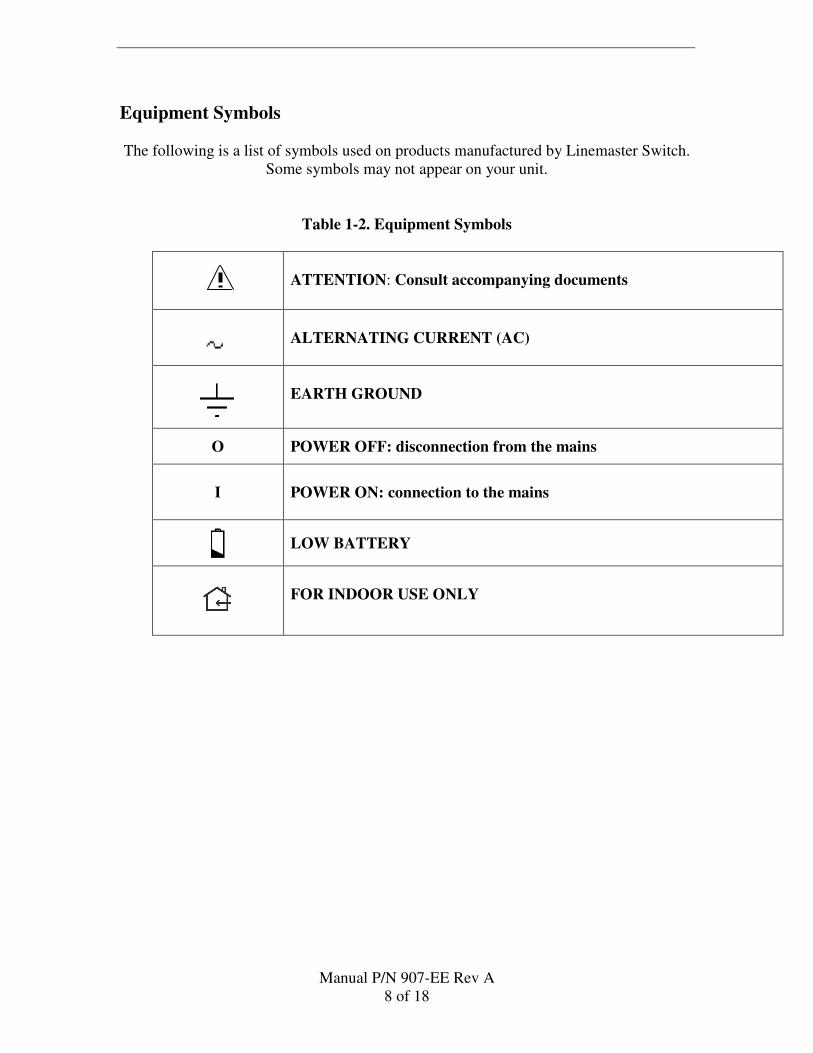
Equipment Symbols
The following is a list of symbols used on products manufactured by Linemaster Switch.
Some symbols may not appear on your unit.
Table 1-2. Equipment Symbols
ATTENTION: Consult accompanying documents
ALTERNATING CURRENT (AC)
EARTH GROUND
O POWER OFF: disconnection from the mains
I
POWER ON: connection to the mains
LOW BATTERY
FOR INDOOR USE ONLY
Manual P/N 907-EE Rev A
9 of 18
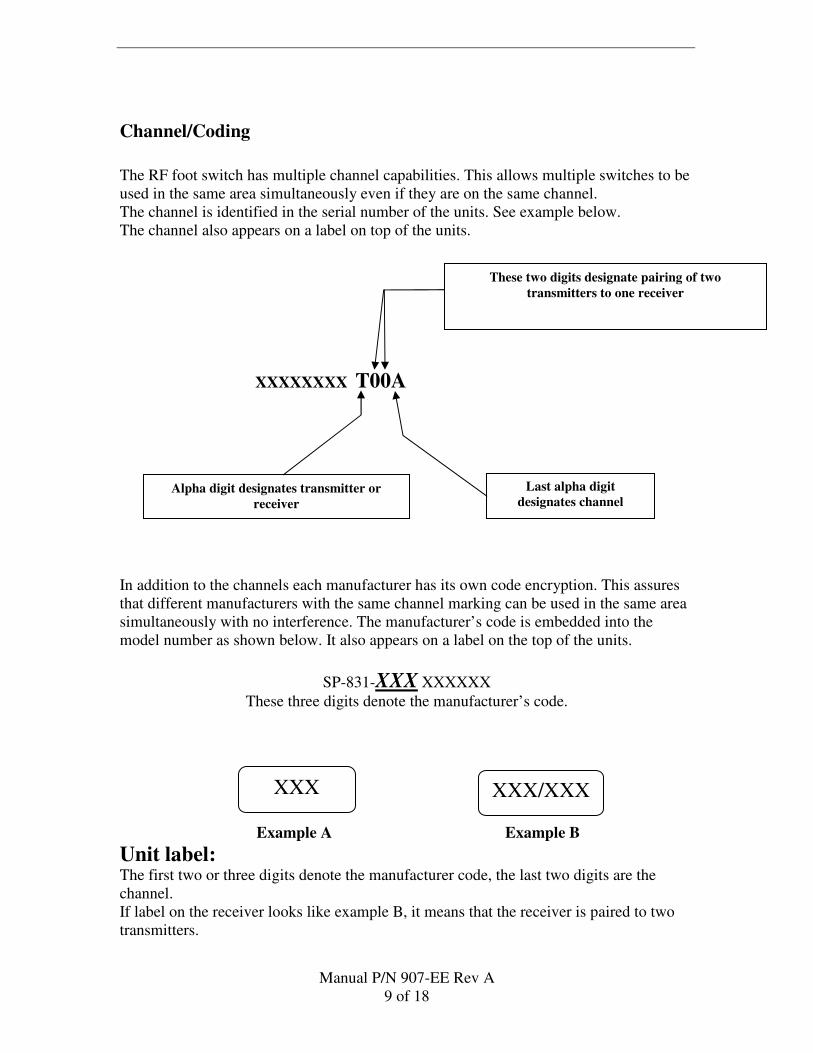
Alpha digit designates transmitter or
receiver
These two digits designate pairing of two
transmitters to one receiver
Last alpha digit
designates channel
Channel/Coding
The RF foot switch has multiple channel capabilities. This allows multiple switches to be
used in the same area simultaneously even if they are on the same channel.
The channel is identified in the serial number of the units. See example below.
The channel also appears on a label on top of the units.
XXXXXXXX T00A
In addition to the channels each manufacturer has its own code encryption. This assures
that different manufacturers with the same channel marking can be used in the same area
simultaneously with no interference. The manufacturer’s code is embedded into the
model number as shown below. It also appears on a label on the top of the units.
SP-831-XXX XXXXXX
These three digits denote the manufacturer’s code.
Unit label: The first two or three digits denote the manufacturer code, the last two digits are the
channel.
If label on the receiver looks like example B, it means that the receiver is paired to two
transmitters.
XXX XXX/XXX
Example A Example B
Manual P/N 907-EE Rev A
10 of 18
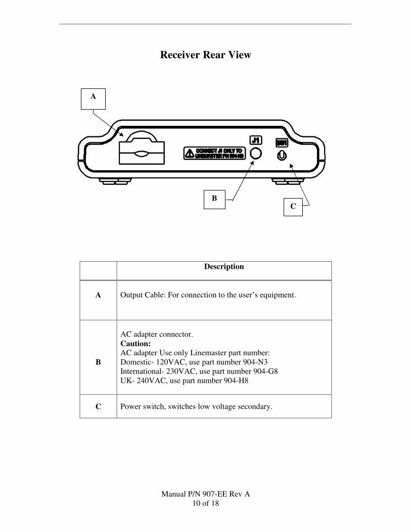
Receiver Rear View
Description
A
Output Cable: For connection to the user’s equipment.
B
AC adapter connector.
Caution:
AC adapter Use only Linemaster part number:
Domestic- 120VAC, use part number 904-N3
International- 230VAC, use part number 904-G8
UK- 240VAC, use part number 904-H8
C Power switch, switches low voltage secondary.
A
C B
Manual P/N 907-EE Rev A
11 of 18
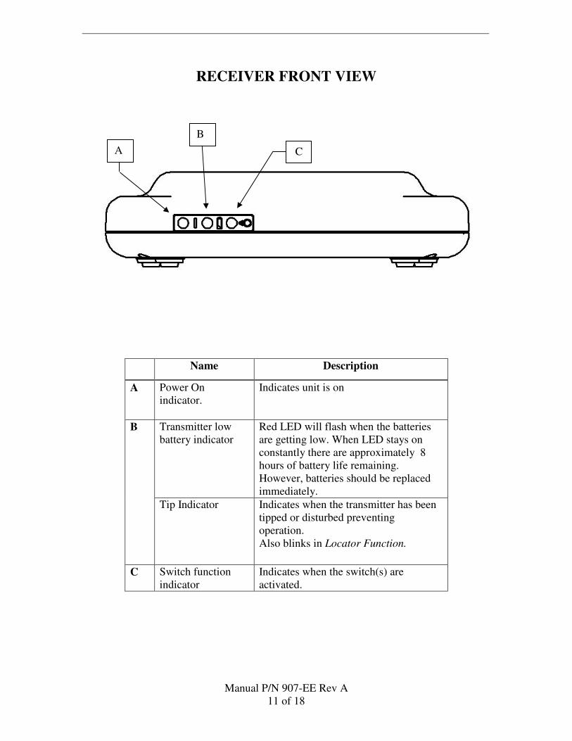
RECEIVER FRONT VIEW
Name Description
A Power On
indicator.
Indicates unit is on
B Transmitter low
battery indicator
Red LED will flash when the batteries
are getting low. When LED stays on
constantly there are approximately 8
hours of battery life remaining.
However, batteries should be replaced
immediately.
Tip Indicator Indicates when the transmitter has been
tipped or disturbed preventing
operation.
Also blinks in Locator Function.
C Switch function
indicator
Indicates when the switch(s) are
activated.
A C
B
Manual P/N 907-EE Rev A
12 of 18
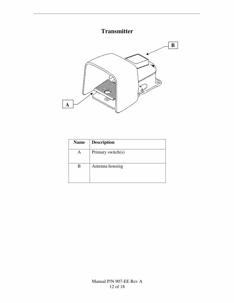
Transmitter
Name Description
A Primary switch(s)
B Antenna housing
A
B
Manual P/N 907-EE Rev A
13 of 18
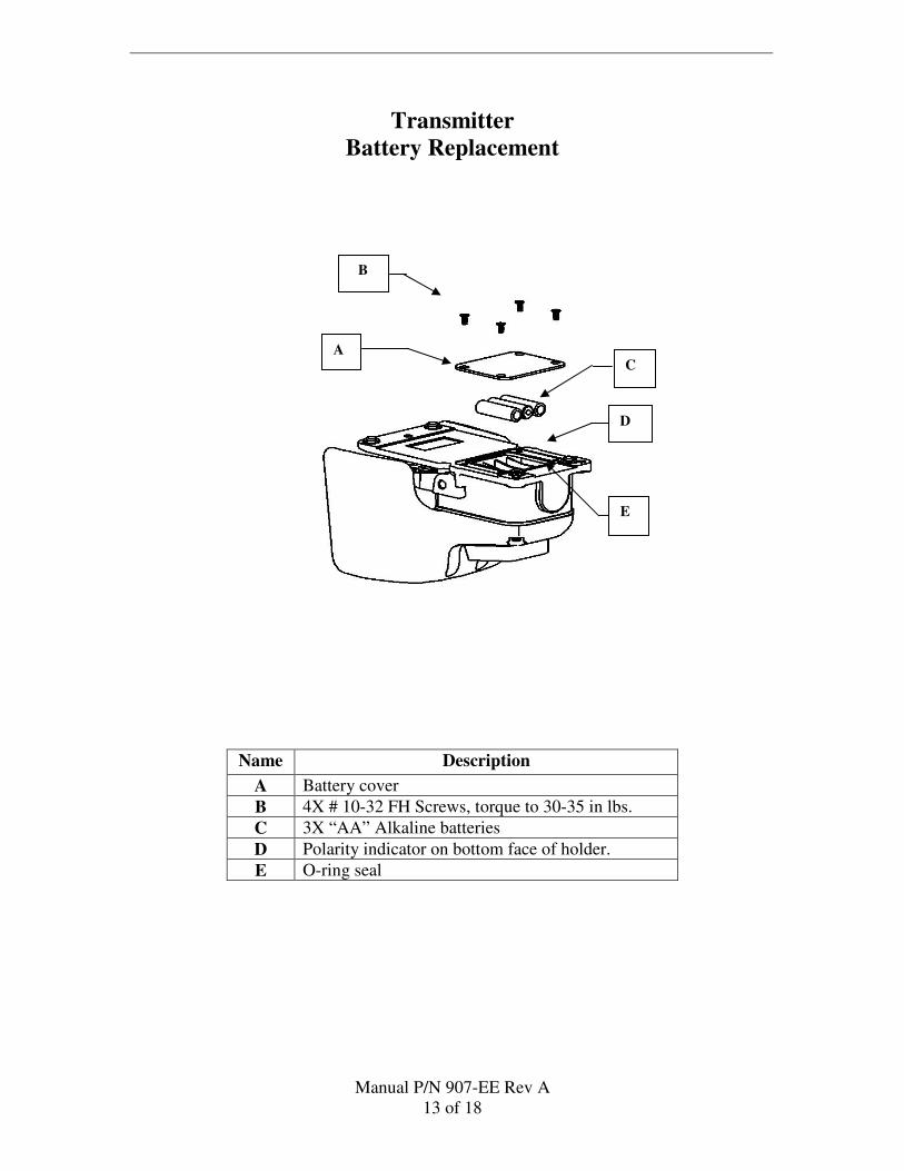
Transmitter
Battery Replacement
Name Description
A Battery cover
B 4X # 10-32 FH Screws, torque to 30-35 in lbs.
C 3X “AA” Alkaline batteries
D Polarity indicator on bottom face of holder.
E O-ring seal
A
B
D
E
C
Manual P/N 907-EE Rev A
14 of 18
Battery Statement
Caution: Replace the batteries in the transmitter with high quality “AA” size alkaline
batteries as shown. Never mix manufacturers when replacing the batteries.
Never mix old and new batteries. Care must be taken when replacing the
batteries not to damage the o-ring seal on the battery cover. The o-ring seal
should be replaced whenever it is damaged or its integrity is in question.
Linemaster recommends the seal should be replaced at the minimum every
third time batteries are replaced. When replacing the seal lubricate it with
petroleum jelly.
Battery Leakage- If the transmitter will not be used for an extended period
of time, remove the batteries to prevent damage due to possible battery
leakage.
Battery disposal- Follow the battery manufacturer’s recommendations or
your facilities policy for the disposal of used batteries.
Manual P/N 907-EE Rev A
15 of 18
Cleaning
The following cleaning instructions are provided.
CAUTIONS:
ABRASION- Do not use abrasive cloth, sharp objects, or abrasive cleaners.
DISCONNECTION- Detach the interconnect cables and the AC adapter from
the receiver.
IMMERSION-Do not immerse the receiver, cables or connectors under running
water.
Transmitter
The transmitter is IP68 rated and can be completely immersed briefly.
Dampen a non-abrasive cloth with one of the following products; then wring out
until slightly wet and gently rub soiled area until clean.
� Isopropyl alcohol
� Soap and water
� Sodium Hypochlorite 5.25% (Bleach) diluted 10:1
Receiver
CAUTION: The receiver is IPX1 rated and cannot be immersed.
Dampen a non-abrasive cloth with one of the following products; then wring out
until slightly wet and gently rub soiled area until clean.
� Isopropyl alcohol
� Soap and water
Wipe any fluids from the surface of the receiver.
Manual P/N 907-EE Rev A
16 of 18
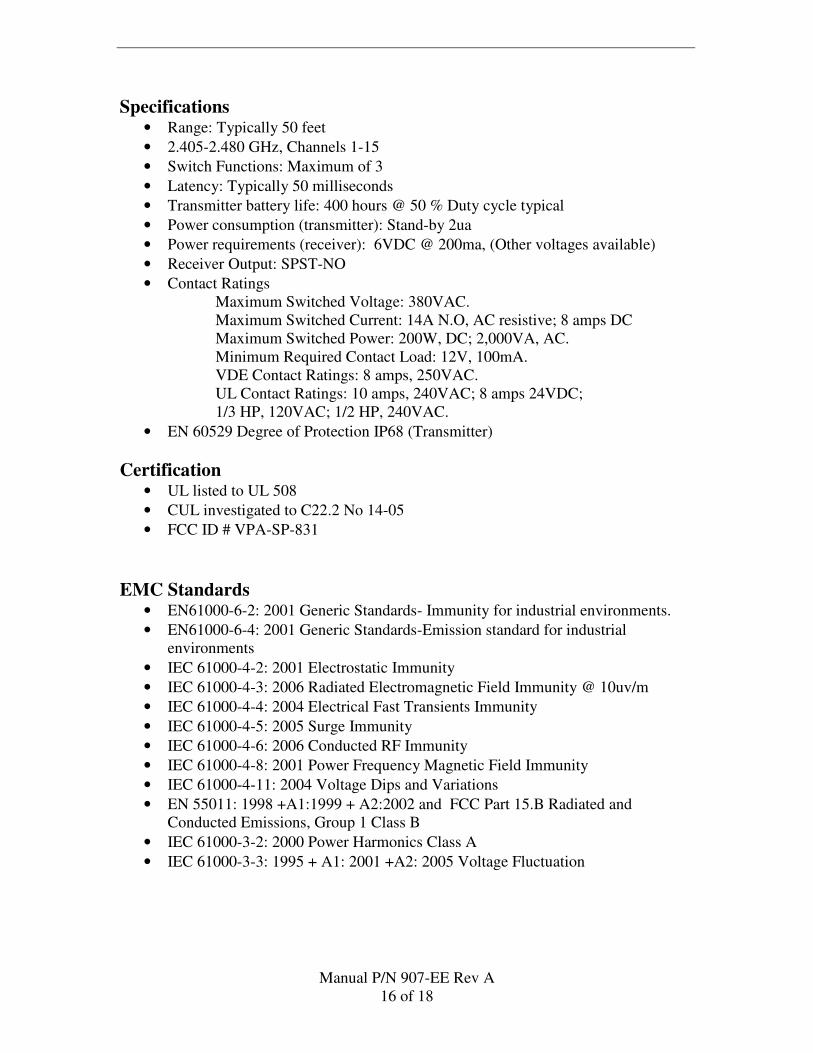
Specifications • Range: Typically 50 feet
• 2.405-2.480 GHz, Channels 1-15
• Switch Functions: Maximum of 3
• Latency: Typically 50 milliseconds
• Transmitter battery life: 400 hours @ 50 % Duty cycle typical
• Power consumption (transmitter): Stand-by 2ua
• Power requirements (receiver): 6VDC @ 200ma, (Other voltages available)
• Receiver Output: SPST-NO
• Contact Ratings
Maximum Switched Voltage: 380VAC.
Maximum Switched Current: 14A N.O, AC resistive; 8 amps DC
Maximum Switched Power: 200W, DC; 2,000VA, AC.
Minimum Required Contact Load: 12V, 100mA.
VDE Contact Ratings: 8 amps, 250VAC.
UL Contact Ratings: 10 amps, 240VAC; 8 amps 24VDC;
1/3 HP, 120VAC; 1/2 HP, 240VAC.
• EN 60529 Degree of Protection IP68 (Transmitter)
Certification • UL listed to UL 508
• CUL investigated to C22.2 No 14-05
• FCC ID # VPA-SP-831
EMC Standards • EN61000-6-2: 2001 Generic Standards- Immunity for industrial environments.
• EN61000-6-4: 2001 Generic Standards-Emission standard for industrial
environments
• IEC 61000-4-2: 2001 Electrostatic Immunity
• IEC 61000-4-3: 2006 Radiated Electromagnetic Field Immunity @ 10uv/m
• IEC 61000-4-4: 2004 Electrical Fast Transients Immunity
• IEC 61000-4-5: 2005 Surge Immunity
• IEC 61000-4-6: 2006 Conducted RF Immunity
• IEC 61000-4-8: 2001 Power Frequency Magnetic Field Immunity
• IEC 61000-4-11: 2004 Voltage Dips and Variations
• EN 55011: 1998 +A1:1999 + A2:2002 and FCC Part 15.B Radiated and
Conducted Emissions, Group 1 Class B
• IEC 61000-3-2: 2000 Power Harmonics Class A
• IEC 61000-3-3: 1995 + A1: 2001 +A2: 2005 Voltage Fluctuation
Manual P/N 907-EE Rev A
17 of 18
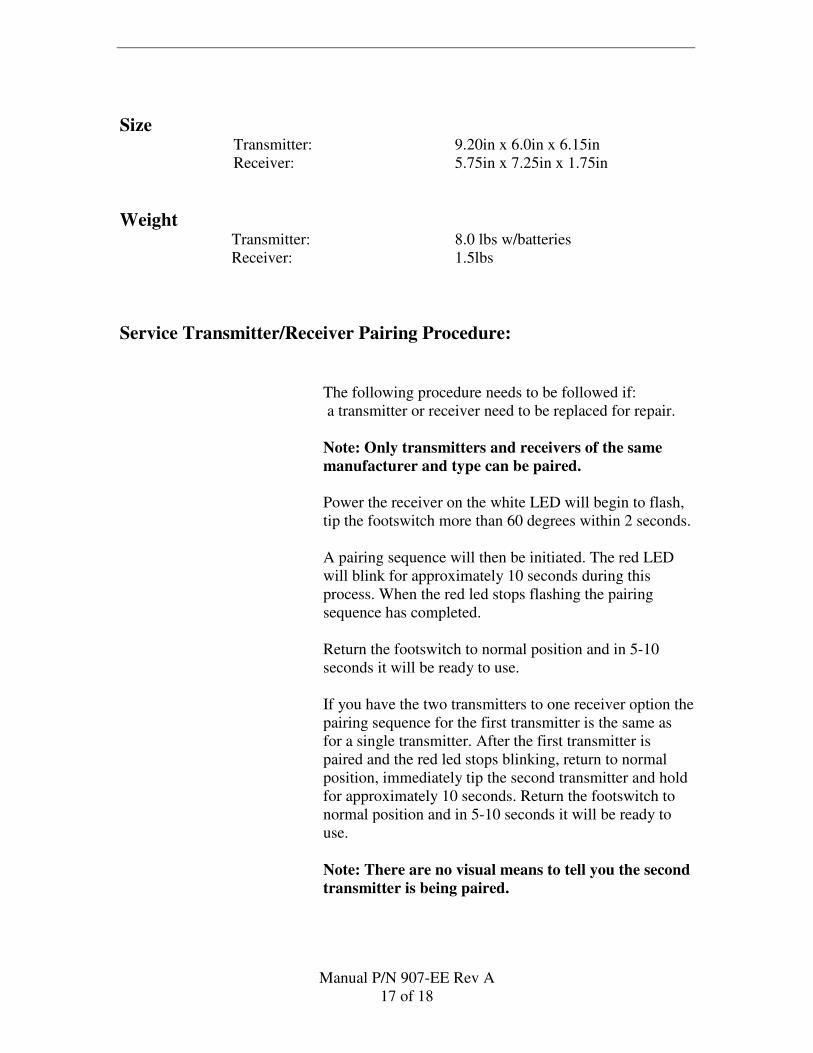
Size Transmitter: 9.20in x 6.0in x 6.15in
Receiver: 5.75in x 7.25in x 1.75in
Weight Transmitter: 8.0 lbs w/batteries
Receiver: 1.5lbs
Service Transmitter/Receiver Pairing Procedure:
The following procedure needs to be followed if:
a transmitter or receiver need to be replaced for repair.
Note: Only transmitters and receivers of the same
manufacturer and type can be paired.
Power the receiver on the white LED will begin to flash,
tip the footswitch more than 60 degrees within 2 seconds.
A pairing sequence will then be initiated. The red LED
will blink for approximately 10 seconds during this
process. When the red led stops flashing the pairing
sequence has completed.
Return the footswitch to normal position and in 5-10
seconds it will be ready to use.
If you have the two transmitters to one receiver option the
pairing sequence for the first transmitter is the same as
for a single transmitter. After the first transmitter is
paired and the red led stops blinking, return to normal
position, immediately tip the second transmitter and hold
for approximately 10 seconds. Return the footswitch to
normal position and in 5-10 seconds it will be ready to
use.
Note: There are no visual means to tell you the second
transmitter is being paired.
Manual P/N 907-EE Rev A
18 of 18
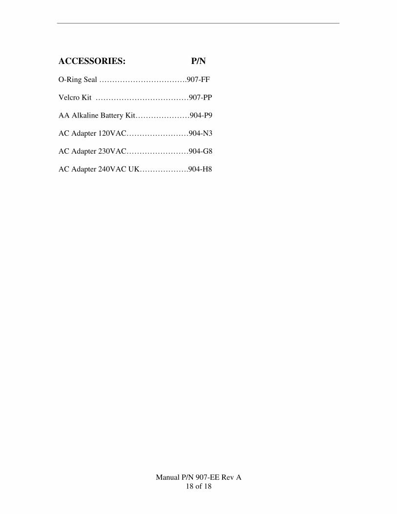
ACCESSORIES: P/N
O-Ring Seal …………………………….907-FF
Velcro Kit ………………………………907-PP
AA Alkaline Battery Kit…………………904-P9
AC Adapter 120VAC……………………904-N3
AC Adapter 230VAC……………………904-G8
AC Adapter 240VAC UK……………….904-H8