Embed Size (px)
Citation preview
RF-IDraw: Virtual Touch Screen in the Air Using RF Signals
Jue Wang, Deepak Vasisht, and Dina KatabiMassachusetts Institute of Technology
{jue_w,deepakv,dk}@mit.edu
ABSTRACT
Prior work in RF-based positioning has mainly focused on dis-covering the absolute location of an RF source, where state-of-the-art systems can achieve an accuracy on the order of tens of centime-ters using a large number of antennas. However, many applicationsin gaming and gesture based interface see more benefits in know-ing the detailed shape of a motion. Such trajectory tracing requiresa resolution several fold higher than what existing RF-based posi-tioning systems can offer.
This paper shows that one can provide a dramatic increase in tra-jectory tracing accuracy, even with a small number of antennas. Thekey enabler for our design is a multi-resolution positioning tech-nique that exploits an intrinsic tradeoff between improving the reso-lution and resolving ambiguity in the location of the RF source. Theunique property of this design is its ability to precisely reconstructthe minute details in the trajectory shape, even when the absoluteposition might have an offset. We built a prototype of our designwith commercial off-the-shelf RFID readers and tags and used it toenable a virtual touch screen, which allows a user to interact with adesired computing device by gesturing or writing her commands inthe air, where each letter is only a few centimeters wide.
1. INTRODUCTION
RF-based positioning has become the next frontier for innova-tion in mobile computing, business analytics, and human-computerinteraction [16, 29, 17]. The topic has attracted much interest fromboth the industry [30, 14, 23, 3] and the research community, whichtranslated to many advanced RF-localization systems [41, 19, 39].So far, however, the literature has mainly focused on the problemof discovering the exact location of an RF source on a buildingfloor [41, 19, 13, 28]. Many applications, on the other hand, caremore about the detailed trajectory of a target as opposed to its exactlocation; for example, in gesture-based user interfaces, it is moreimportant to be able to precisely track the shape of a gesture withhigh resolution and fidelity, while the actual position may still havean offset. For such applications, existing schemes cannot reproducean accurate version of the trajectory shape to satisfy the applica-tions’ needs.
This paper introduces RF-IDraw, a system that can accuratelytrace the trajectory of an RF source, particularly an RFID. RF-IDraw’s trajectory tracing is so accurate that it enables a virtual
touch screen based on RF signals. Today, a user can write, scroll,or swipe on a touch screen of a smart phone or tablet. Taking thisa step further, RF-IDraw allows a user to input her commands by
Permission to make digital or hard copies of all or part of this work for personal or
classroom use is granted without fee provided that copies are not made or distributed
for profit or commercial advantage and that copies bear this notice and the full citation
on the first page. Copyrights for components of this work owned by others than the
author(s) must be honored. Abstracting with credit is permitted. To copy otherwise, or
republish, to post on servers or to redistribute to lists, requires prior specific permission
and/or a fee. Request permissions from [email protected].
SIGCOMM’14, August 17–22, 2014, Chicago, IL, USA.
Copyright is held by the owner/author(s). Publication rights licensed to ACM.
ACM 978-1-4503-2836-4/14/08 ...$15.00.
http://dx.doi.org/10.1145/2619239.2626330 .
(a) RFID
-2010
010
20 40 60 80 100 120
100
120
140
160
x (cm)y (cm)
z (
cm
)
(b) Reconstructed Word
Figure 1—Enabling Virtual Touch Screen: By accurately tracingthe trajectory shape of an RFID on the user’s finger, RF-IDraw cantransform any plane or surface into a virtual touch screen, allowingthe user to input her commands in the air using RF signals.
(a) 2-Antenna Array Beam (b) 4-Antenna Array Beam
Figure 2—Antenna Array Beam Resolution: The figure showsan RF source in blue, and the beams of two antenna arrays with 2and 4 antenna elements each. The more antennas in the array, thenarrower its beam, and the tighter it can bound the source direction.
writing, scrolling, swiping, etc., without being in physical touchwith a screen – the user can write in the air any word or commandusing an RFID attached to a pen or a finger splint, as shown inFig. 1(a). RF-IDraw would reconstruct the RFID’s trajectory andinterpret the user’s writing and gestures as input to the desired com-puting device. Essentially, RF-IDraw can transform any plane orsurface in space into a virtual touch screen. Fig. 1(b) shows an ex-ample of RF-IDraw’s output which was entered by writing in theair using an RFID on the user’s finger. Such a virtual touch screencan be used to realize a variety of applications. For example, it canbe used to interact with a remote screen, to send commands to a cellphone without touching it, or to interface with small devices (e.g.,sensors) that do not have space for a keyboard.
RF-IDraw’s technology is based on the realization that a dif-ferent design principle for leveraging multiple antennas can leadto a significant improvement in both tracing and localization ac-curacy. Specifically, state-of-the-art RF-based positioning systemstypically use an antenna array, and leverage its beamsteering capa-bility to detect the direction of the source [41, 39, 12, 21]. The loca-tion of the source can then be computed by intersecting the beamsof multiple such arrays. Hence, to obtain a high accuracy, they needan array with a narrow beam, which requires a large number of an-tennas. For example, Fig. 2 compares the beam width of 2-antennaand 4-antenna arrays; both have the default antenna spacing of λ
2,
(a) λ2
Separation (b) λ Separation (c) 8λ Separation
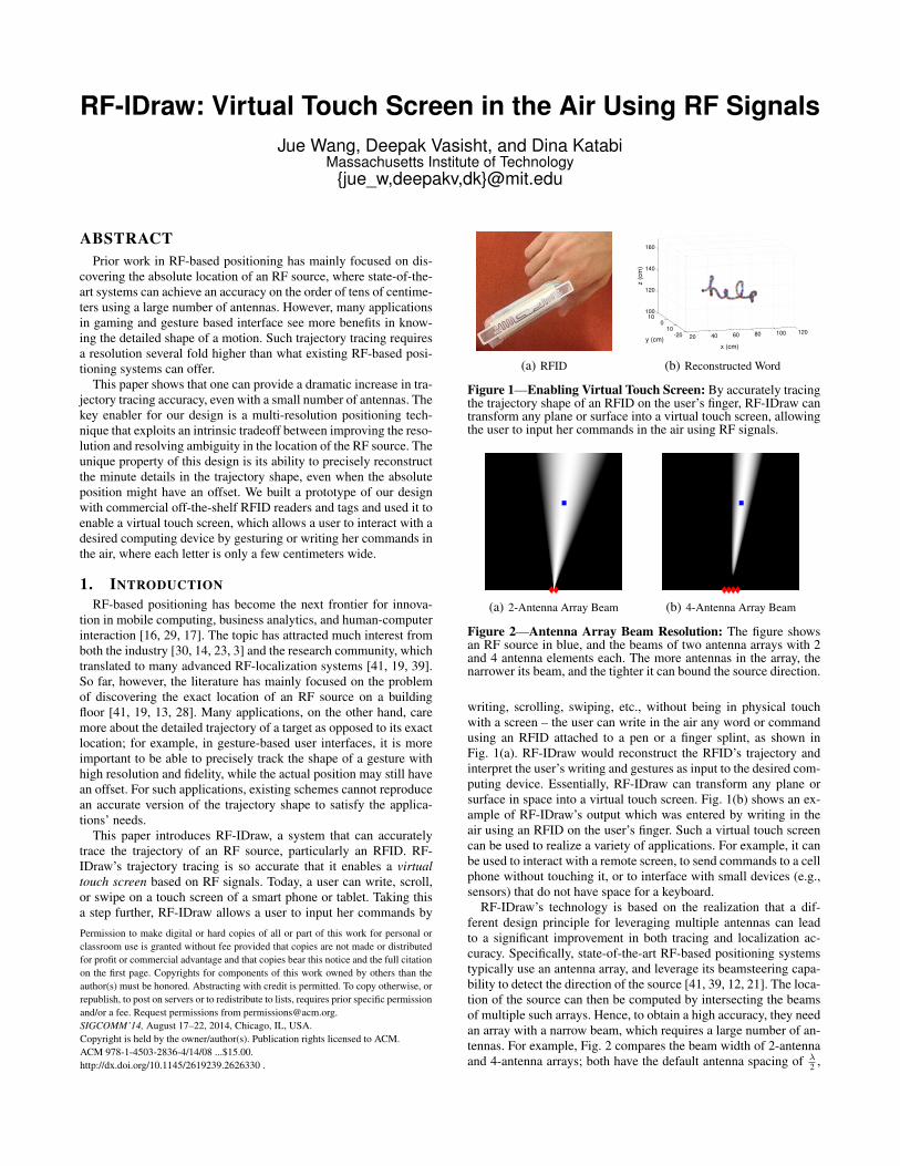
Figure 3—Tradeoff Between Improving Resolution and Removing Ambiguity: Asthe separation of the antenna pair (marked in red) increases, the number of beams in-creases accordingly, causing ambiguity in localizing the source (marked in blue). Onthe other hand, each beam gets narrower, leading to a higher resolution.
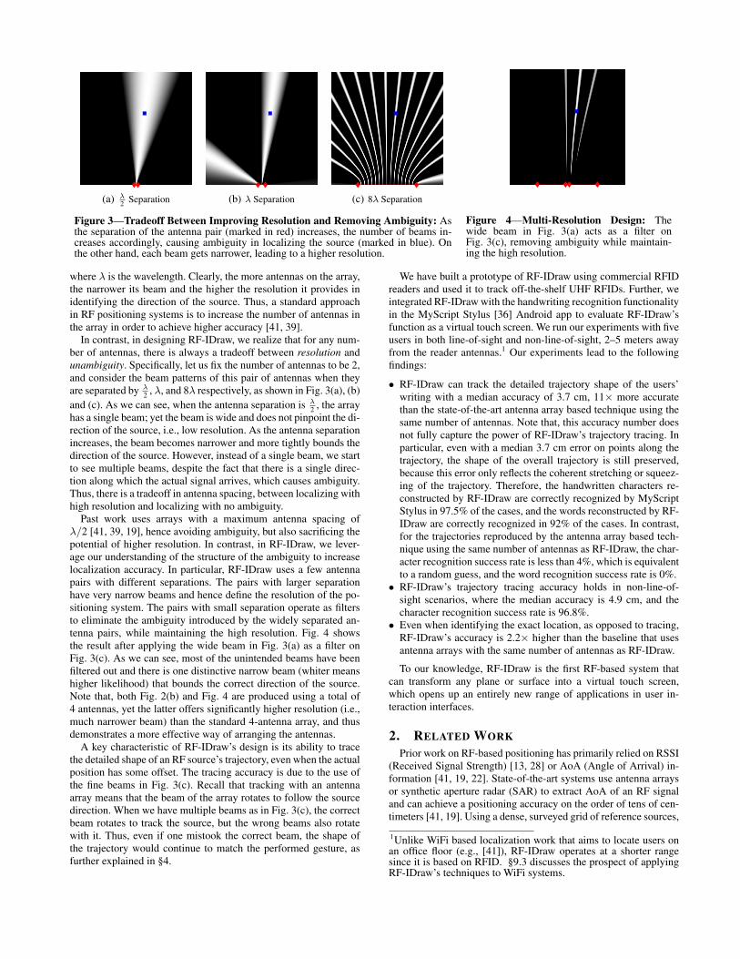
Figure 4—Multi-Resolution Design: Thewide beam in Fig. 3(a) acts as a filter onFig. 3(c), removing ambiguity while maintain-ing the high resolution.
where λ is the wavelength. Clearly, the more antennas on the array,the narrower its beam and the higher the resolution it provides inidentifying the direction of the source. Thus, a standard approachin RF positioning systems is to increase the number of antennas inthe array in order to achieve higher accuracy [41, 39].
In contrast, in designing RF-IDraw, we realize that for any num-ber of antennas, there is always a tradeoff between resolution andunambiguity. Specifically, let us fix the number of antennas to be 2,and consider the beam patterns of this pair of antennas when theyare separated by λ
2, λ, and 8λ respectively, as shown in Fig. 3(a), (b)
and (c). As we can see, when the antenna separation is λ2
, the arrayhas a single beam; yet the beam is wide and does not pinpoint the di-rection of the source, i.e., low resolution. As the antenna separationincreases, the beam becomes narrower and more tightly bounds thedirection of the source. However, instead of a single beam, we startto see multiple beams, despite the fact that there is a single direc-tion along which the actual signal arrives, which causes ambiguity.Thus, there is a tradeoff in antenna spacing, between localizing withhigh resolution and localizing with no ambiguity.
Past work uses arrays with a maximum antenna spacing ofλ/2 [41, 39, 19], hence avoiding ambiguity, but also sacrificing thepotential of higher resolution. In contrast, in RF-IDraw, we lever-age our understanding of the structure of the ambiguity to increaselocalization accuracy. In particular, RF-IDraw uses a few antennapairs with different separations. The pairs with larger separationhave very narrow beams and hence define the resolution of the po-sitioning system. The pairs with small separation operate as filtersto eliminate the ambiguity introduced by the widely separated an-tenna pairs, while maintaining the high resolution. Fig. 4 showsthe result after applying the wide beam in Fig. 3(a) as a filter onFig. 3(c). As we can see, most of the unintended beams have beenfiltered out and there is one distinctive narrow beam (whiter meanshigher likelihood) that bounds the correct direction of the source.Note that, both Fig. 2(b) and Fig. 4 are produced using a total of4 antennas, yet the latter offers significantly higher resolution (i.e.,much narrower beam) than the standard 4-antenna array, and thusdemonstrates a more effective way of arranging the antennas.
A key characteristic of RF-IDraw’s design is its ability to tracethe detailed shape of an RF source’s trajectory, even when the actualposition has some offset. The tracing accuracy is due to the use ofthe fine beams in Fig. 3(c). Recall that tracking with an antennaarray means that the beam of the array rotates to follow the sourcedirection. When we have multiple beams as in Fig. 3(c), the correctbeam rotates to track the source, but the wrong beams also rotatewith it. Thus, even if one mistook the correct beam, the shape ofthe trajectory would continue to match the performed gesture, asfurther explained in §4.
We have built a prototype of RF-IDraw using commercial RFIDreaders and used it to track off-the-shelf UHF RFIDs. Further, weintegrated RF-IDraw with the handwriting recognition functionalityin the MyScript Stylus [36] Android app to evaluate RF-IDraw’sfunction as a virtual touch screen. We run our experiments with fiveusers in both line-of-sight and non-line-of-sight, 2–5 meters awayfrom the reader antennas.1 Our experiments lead to the followingfindings:
• RF-IDraw can track the detailed trajectory shape of the users’writing with a median accuracy of 3.7 cm, 11× more accuratethan the state-of-the-art antenna array based technique using thesame number of antennas. Note that, this accuracy number doesnot fully capture the power of RF-IDraw’s trajectory tracing. Inparticular, even with a median 3.7 cm error on points along thetrajectory, the shape of the overall trajectory is still preserved,because this error only reflects the coherent stretching or squeez-ing of the trajectory. Therefore, the handwritten characters re-constructed by RF-IDraw are correctly recognized by MyScriptStylus in 97.5% of the cases, and the words reconstructed by RF-IDraw are correctly recognized in 92% of the cases. In contrast,for the trajectories reproduced by the antenna array based tech-nique using the same number of antennas as RF-IDraw, the char-acter recognition success rate is less than 4%, which is equivalentto a random guess, and the word recognition success rate is 0%.
• RF-IDraw’s trajectory tracing accuracy holds in non-line-of-sight scenarios, where the median accuracy is 4.9 cm, and thecharacter recognition success rate is 96.8%.
• Even when identifying the exact location, as opposed to tracing,RF-IDraw’s accuracy is 2.2× higher than the baseline that usesantenna arrays with the same number of antennas as RF-IDraw.
To our knowledge, RF-IDraw is the first RF-based system thatcan transform any plane or surface into a virtual touch screen,which opens up an entirely new range of applications in user in-teraction interfaces.
2. RELATED WORK
Prior work on RF-based positioning has primarily relied on RSSI(Received Signal Strength) [13, 28] or AoA (Angle of Arrival) in-formation [41, 19, 22]. State-of-the-art systems use antenna arraysor synthetic aperture radar (SAR) to extract AoA of an RF signaland can achieve a positioning accuracy on the order of tens of cen-timeters [41, 19]. Using a dense, surveyed grid of reference sources,
1Unlike WiFi based localization work that aims to locate users onan office floor (e.g., [41]), RF-IDraw operates at a shorter rangesince it is based on RFID. §9.3 discusses the prospect of applyingRF-IDraw’s techniques to WiFi systems.
several schemes can achieve a higher accuracy of a few centime-ters by identifying the nearest references [39, 37]. For example, thework in [37] leverages the motion of a robot equipped with refer-ence RFIDs to enable centimeter-scale accuracy in grasping an ob-ject tagged with RFIDs. RF-IDraw differs from these past schemesin both techniques and capabilities. By effectively exploiting thehigh resolution of antenna pairs with large separations, RF-IDrawoffers unmatched accuracy in tracking an RF device’s detailed tra-jectory without the use of references. As such, it enables a wholenew class of applications which are previously infeasible using RFsignals, such as virtual touch screen in the air.
The conception and design of RF-IDraw are inspired by astro-nomical interferometry, where telescopes are used to image thesky and search for planets [20, 34, 2]. In particular, in astron-omy, pairs of telescopes with large separation are used to producehigh-resolution fringes. One can consider these telescopes as an-tennas. The narrow beams produced by RF-IDraw’s antenna pairswith large separation and the fringes in interferometry are similarin nature, i.e., both offer high resolution at the cost of ambiguity.Ambiguity in interferometry is resolved using delay lines whicheffectively orient each telescope pair towards a particular part ofthe sky, whereas in RF-IDraw, we use a pair of antennas with smallseparation to focus on a particular region in the area of interest. Fur-thermore, in astronomy, the rotation of the Earth/sky is exploited tofacilitate better coverage and accuracy. In RF-IDraw, although wedo not have a known motion like the rotation of the Earth to lever-age, we integrate information gathered throughout the trajectory ofthe RF device to improve the elimination of ambiguity, which hasa similar flavor. However, while the underlying intuition is trans-ferable between the two, RF-IDraw’s algorithms, signal processingtechniques, and applications significantly differ from astronomicalinterferometry.
In the context of RF antenna arrays, recently there is a growinginterest in exploring the use of sparse arrays to estimate the angleof arrival [31, 25, 18]. For example, [31, 25] propose the use of co-prime sampling in a large uniform linear array to reduce the numberof antennas needed; [18] evaluates the use of compressive sensingin sampling the antenna positions. By virtue of emulating very largearrays, these schemes show asymptotic improvement over the naiveAoA approach through theoretical analyses. However, for a smallnumber of antennas available to our application of interest (i.e., 8 intotal), the asymptotic analysis does not lead to any meaningful gain,and hence these proposals cannot achieve the resolution enabled byRF-IDraw. Furthermore, they focus on estimating a single measure-ment of angle of arrival, as opposed to tracing the trajectory shapeas RF-IDraw does.
Systems such as [7] and [32] make use of depth sensors (e.g.,Kinect) and infrared cameras (e.g., Wii) to turn a projector screenor wall into a touch screen and allow a user to interact with thedisplay using a specially designed pen. RF-IDraw is the first RF-based virtual touch screen; unlike solutions based on depth imagingor infrared, it does not require line-of-sight to work. Further, sinceRF sources have unique IDs (e.g., RFID EPC ID [15]), it is easy toscale to a larger number of users simultaneously interacting throughthe virtual touch screen without causing confusion.
Finally, RF-IDraw’s application is inspired by recent work onmotion tracking [27, 10, 9] which uses RF signals to enable a userto interact with the environment. Differing from these systems, RF-IDraw is the first RF-based solution that can accurately reconstructthe detailed trajectory of a user’s writing or gesturing in the air,where each letter or gesture is only a few centimeters wide. Such ca-pability is not supported by prior work in RF-based gesture recog-nition. For example, [27] presents a state-of-the-art WiFi-based in-
, ,
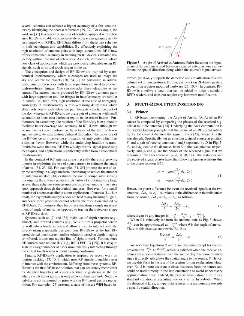
Figure 5—Angle of Arrival at Antenna Pair: Based on the signalphase difference measured between a pair of antennas, one can es-timate the spatial direction along which the source’s signal arrives.
terface, yet it only supports the detection and classification of a pre-defined set of nine gestures. Further, past work on RF-based gesturerecognition requires modified hardware [27, 10, 9]. In contrast, RF-IDraw is a software patch that can be added to today’s standardRFID readers, and does not require any hardware modification.
3. MULTI-RESOLUTION POSITIONING
3.1 Primer
In RF-based positioning, the Angle of Arrival (AoA) of an RFsource is computed by comparing the phases of the received sig-nals at multiple antennas [24]. Underlying the AoA computation isthe widely known principle that the phase of an RF signal rotatesby 2π for every λ distance the signal travels [35], where λ is thewavelength. Specifically, let us consider a signal source at positionS, and a pair of receive antennas i and j separated by D in Fig. 5.dS,i and dS,j denote the distances from S to the two antennas respec-tively, and φi and φj are the phases of the received signal that wemeasure at the two antennas. φi,φj ∈ [0, 2π). The distances andthe received signal phases have the following known relations dueto the phase rotation [35]:
φi = −mod(2π
λdS,i, 2π)
φj = −mod(2π
λdS,j, 2π)
(1)
Hence, the phase difference between the received signals at the twoantennas, ∆φj,i = φj−φi, relates to the difference in their distancesfrom the source, ∆di,j = dS,i − dS,j, as follows:
∆di,j
λ=
∆φj,i
2π+ k, (2)
where k can be any integer in [−D
λ−
∆φj,i
2π, D
λ−
∆φj,i
2π].
When S is relatively far from the antenna pair, as Fig. 5 shows,∆di,j
λcan be approximated as D cos θ
λwhere θ is the angle of arrival.
Thus, in this case we can rewrite Eq. 2 as
D cos θ
λ=
∆φj,i
2π+ k (3)
We note that Equations 2 and 3 are the same except for the ap-
proximation∆di,j
λ≈ D cos θ
λ, which is satisfied when the receive an-
tennas are at some distance from the source. Eq. 3 is more intuitivesince it directly articulates the spatial angle to the source, θ. Hence,we use this form in the rest of the section for our explanation. How-ever, Eq. 2 is more accurate at close distances from the source andcould be used directly in the implementation to avoid unnecessaryapproximation noise. Indeed, the precise formulation in Eq. 2 is astandard equation representing one or a set of hyperbolas. Whenthe distance is large, a hyperbola reduces to a ray pointing towardsa specific spatial direction.
3.2 Grating Lobes
There is a tradeoff between increasing the resolution and remov-ing the ambiguity in detecting a signal’s angle of arrival. As Fig. 3shows, when the separation between the two antennas is greaterthan λ/2, the beam pattern exhibits multiple beams, although thereis only one direction along which the signal arrives. The additionalbeams are often referred to as grating lobes [24].
Here we explain the cause and characteristics of grating lobesin the context of angle of arrival. For a particular phase differencemeasured ∆φj,i, there are one or a set of spatial angles θ that satisfyEq. 3. Specifically, since cos θ ∈ [−1, 1], when D ≤ λ/2, k cantake only one value which is 0. Thus, in this case, we can derive a
unique angle of arrival θ = arccos(λD
∆φj,i
2π), which means we will
observe a single beam in the antenna pair’s beam pattern.As D increases, the number of possible k values increases. For
D = K λ2
, the number of possible values k can take is K. Hence,there are K different values of θ that will satisfy Eq. 3: θ =
arccos(λD
∆φj,i
2π+ kλ
D), only one of which refers to the actual angle of
arrival. This is where ambiguity arises. We will see multiple beams(i.e., grating lobes) in the antenna pair’s beam pattern correspond-ing to the multiple spatial angles. In summary, each grating lobecorresponds to one spatial direction θ, and the number of gratinglobes increases linearly with the antenna separation D.
3.3 Resolution and Robustness to Noise
Since grating lobes cause ambiguity in deciding the actual angleof arrival, they are typically considered detrimental and past RFlocalization systems try to avoid them by imposing the constraintthat adjacent antennas must be separated by no more than λ
2[41,
39]. However, while grating lobes introduce ambiguity, there aretwo properties about grating lobes that are highly desirable in thecontext of localization: high resolution and robustness to noise.
Resolution: Let us first look at the resolution of the spatial angle ofarrival as computed by an antenna pair with D separation. We canrewrite Eq. 3 as
cos θ =λ
D
∆φj,i
2π+
kλ
D. (4)
Recall that the value we can measure is the signal’s phase differ-ence, ∆φj,i, and the value we intend to compute is the signal’s spa-tial angle of arrival θ. Any hardware has some resolution, δ, for howit expresses φj,i and hence ∆φj,i. The value of δ defines the mini-mum measurable change in ∆φj,i, and hence the finest quantizationof cos θ, i.e., its resolution. In particular, the finest quantization wehave in computing cos θ is λ
D
δ2π
. As the antenna separation D in-creases (i.e., more grating lobes), the minimum quantization levelfor expressing cos θ decreases, leading to a finer resolution in esti-mating the spatial angle θ.
Robustness to Noise: In addition to providing high resolution, grat-ing lobes of antenna pairs with a large separation also prove to bemore robust to wireless noise. Eq. 4 represents the noise-free case.Now let us take into consideration a phase noise term φn in themeasured phase difference:
cos θ =λ
D
∆φj,i + φn
2π+
kλ
D(5)
Eq. 5 shows that as D increases, cos θ’s sensitivity to phase noiseφn decreases linearly. To put this into perspective, when the phasedifference measurement has a φn = π
5noise, that translates into 0.2
additive error in cos θ if D = λ2
. But if we increase the separationto D = 8λ, the same signal phase noise of φn = π
5would only lead
to 0.0125 additive error in cos θ, which is minimal. Thus, the larger
the antenna pair separation is, the less effect wireless noise has onthe spatial angle of arrival, i.e., the more resilient the system is.
3.4 Intersecting Grating Lobes for Positioning
The discussion above shows that grating lobes of a widely sepa-rated antenna pair offer high resolution and noise resilience in de-tecting the spatial angle of a signal source. To actually localize anRF source, we need to translate knowledge about the spatial angleof the source into information about the source position. To do so,we can intersect the grating lobes of multiple antenna pairs.
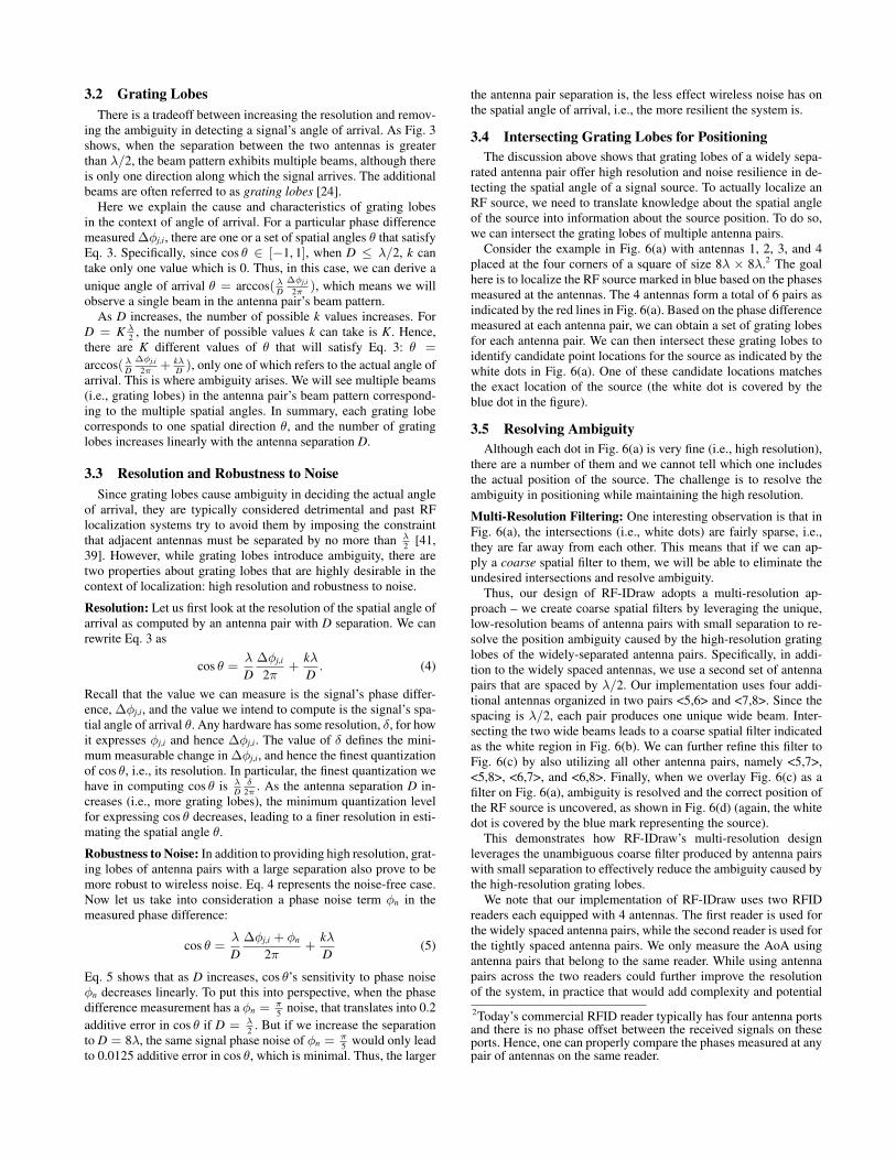
Consider the example in Fig. 6(a) with antennas 1, 2, 3, and 4placed at the four corners of a square of size 8λ × 8λ.2 The goalhere is to localize the RF source marked in blue based on the phasesmeasured at the antennas. The 4 antennas form a total of 6 pairs asindicated by the red lines in Fig. 6(a). Based on the phase differencemeasured at each antenna pair, we can obtain a set of grating lobesfor each antenna pair. We can then intersect these grating lobes toidentify candidate point locations for the source as indicated by thewhite dots in Fig. 6(a). One of these candidate locations matchesthe exact location of the source (the white dot is covered by theblue dot in the figure).
3.5 Resolving Ambiguity
Although each dot in Fig. 6(a) is very fine (i.e., high resolution),there are a number of them and we cannot tell which one includesthe actual position of the source. The challenge is to resolve theambiguity in positioning while maintaining the high resolution.
Multi-Resolution Filtering: One interesting observation is that inFig. 6(a), the intersections (i.e., white dots) are fairly sparse, i.e.,they are far away from each other. This means that if we can ap-ply a coarse spatial filter to them, we will be able to eliminate theundesired intersections and resolve ambiguity.
Thus, our design of RF-IDraw adopts a multi-resolution ap-proach – we create coarse spatial filters by leveraging the unique,low-resolution beams of antenna pairs with small separation to re-solve the position ambiguity caused by the high-resolution gratinglobes of the widely-separated antenna pairs. Specifically, in addi-tion to the widely spaced antennas, we use a second set of antennapairs that are spaced by λ/2. Our implementation uses four addi-tional antennas organized in two pairs <5,6> and <7,8>. Since thespacing is λ/2, each pair produces one unique wide beam. Inter-secting the two wide beams leads to a coarse spatial filter indicatedas the white region in Fig. 6(b). We can further refine this filter toFig. 6(c) by also utilizing all other antenna pairs, namely <5,7>,<5,8>, <6,7>, and <6,8>. Finally, when we overlay Fig. 6(c) as afilter on Fig. 6(a), ambiguity is resolved and the correct position ofthe RF source is uncovered, as shown in Fig. 6(d) (again, the whitedot is covered by the blue mark representing the source).
This demonstrates how RF-IDraw’s multi-resolution designleverages the unambiguous coarse filter produced by antenna pairswith small separation to effectively reduce the ambiguity caused bythe high-resolution grating lobes.
We note that our implementation of RF-IDraw uses two RFIDreaders each equipped with 4 antennas. The first reader is used forthe widely spaced antenna pairs, while the second reader is used forthe tightly spaced antenna pairs. We only measure the AoA usingantenna pairs that belong to the same reader. While using antennapairs across the two readers could further improve the resolutionof the system, in practice that would add complexity and potential
2Today’s commercial RFID reader typically has four antenna portsand there is no phase offset between the received signals on theseports. Hence, one can properly compare the phases measured at anypair of antennas on the same reader.
3
41
2
(a) Intersecting grating lobes toprovide high resolution
56
7 8
(b) Coarse spatial filter obtainedby intersecting wide beams
87
56
(c) Finer spatial filter
1
2 3
4
87
56
(d) Removing ambiguity whilemaintaining high resolution
Figure 6—Multi-Resolution Positioning: This figure shows an example of using RF-IDraw’s multi-resolution positioning to localize a signalsource marked in blue. The red dotted lines represent which antenna pairs are used in each subplot. (a) shows the common intersections ofdifferent antenna pairs’ grating lobes, which offer high resolution in positioning yet causing ambiguity. (b) shows a coarse spatial filter formedby intersecting the wide beams of two tightly spaced antenna pairs. (c) shows the finer filter obtained when four more antenna pairs withlarger separation are used to refine (b). Applying the filter in (c) on (a) eliminates ambiguity and uncovers the correct position as (d) shows.
errors because the phase offset between the two readers will needto be calibrated or removed. Hence, in our implementation, we onlyuse antenna pairs within the same reader.
4. THE POWER OF GRATING LOBES FOR TRA-
JECTORY TRACING
Instead of just localizing a static device, many applications ingaming, smart homes, and healthcare are more interested in track-ing the trajectory of an RF source as it moves. The unique propertyof RF-IDraw’s grating lobe based approach is its ability to accu-rately detect the shape of a trajectory. In fact, this is true even inthe case where there are errors in the absolute positioning alongthe trajectory. For example, one may get the initial point of wherethe trajectory starts wrong by a small offset, yet the shape of RF-IDraw’s reconstructed trajectory will still match the actual shapeof the trajectory with very high fidelity. This property is desirablefor many applications, such as gesture recognition and virtual touchscreen. In these applications, it is important to recognize the gestureor writing of the user, while a small offset in the exact location ofthe gesture is tolerable.
To provide an intuition for why RF-IDraw’s design has this prop-erty, let us start with the basic case of a standard antenna array.Consider the scenario where the RF source is moving along a con-tinuous trajectory. In the case of an antenna array, tracing the tra-jectory of this source means that the antenna array’s beam will ro-tate accordingly with the movement of the source such that it keepspointing towards the source. Now consider what happens when wehave grating lobes. The actual source will be on one of these grat-ing lobes. As the source moves, the correct grating lobe will rotatesuch that it continues to track the source direction. However, sinceall grating lobes rotate together, they will all follow the movementof the source. Hence, even if one makes the wrong assumption thatthe source lies on a particular grating lobe which differs from thecorrect one, this wrong grating lobe’s motion (i.e., rotation in par-ticular) does not fundamentally differ from the motion of the correctgrating lobe as it tracks the source direction.
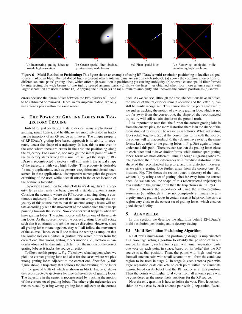
To illustrate this property, Fig. 7(a) shows what happens when wepick the correct grating lobe and also for the cases where we pickwrong grating lobes adjacent to the correct one. Specifically, thisfigure shows a trajectory that follows the handwriting of the letter’q’, the ground truth of which is shown in black. Fig. 7(a) showsthe reconstructed trajectories for nine different sets of grating lobes.The trajectory in the center is reconstructed by tracking the motionof the correct set of grating lobes. The other eight trajectories arereconstructed by using wrong grating lobes adjacent to the correct
ones. As we can see, although the absolute positions have an offset,the shapes of the trajectories remain accurate and the letter ’q’ canstill be easily recognized. This demonstrates the point that even ifwe end up tracking the motion of a wrong grating lobe, which is nottoo far away from the correct one, the shape of the reconstructedtrajectory will still remain similar to the ground truth.
It is important to note that, the further the correct grating lobe isfrom the one we pick, the more distortion there is in the shape of thereconstructed trajectory. The reason is as follows. While all gratinglobes rotate together, (i.e., if the correct one turns with the source,the others will turn accordingly), they do not have exactly the sameforms. Let us refer to the grating lobes in Fig. 3(c) again to betterunderstand this point. There we can see that the grating lobes closeto each other tend to have similar forms, while further apart gratinglobes’ forms are more different. Thus, although all grating lobes ro-tate together, their form differences will introduce distortion to theshape of the reconstructed trajectory, and this distortion increasesas we pick a grating lobe further away from the correct one. Forinstance, Fig. 7(b) shows the reconstructed trajectory of the hand-written ’q’ by using a set of grating lobes far away from the correctones. As we can see, the shape of this reconstructed trajectory isless similar to the ground truth than the trajectories in Fig. 7(a).
This emphasizes the importance of using the multi-resolutionsystem in §3. Although it may not completely eliminate the am-biguity among grating lobes in certain cases, it helps confine us to aregion very close to the correct set of grating lobes, which ensuresgood shape fidelity.
5. ALGORITHM
In this section, we describe the algorithm behind RF-IDraw’smulti-resolution positioning and trajectory tracing.
5.1 Multi-Resolution Positioning Algorithm
RF-IDraw’s multi-resolution positioning design is implementedas a two-stage voting algorithm to identify the position of an RFsource. In stage 1, each antenna pair with small separation castsone vote on each point in space, based on its belief that the RFsource is at that position. Then, the points with high total votesfrom all antenna pairs with small separation will form the candidateregion to be used in stage 2. In stage 2, each antenna pair withlarge separation casts one vote on each point within the candidateregion, based on its belief that the RF source is at this position.Then the points with higher total votes from all antenna pairs willbe considered as the more likely positions for the RF source.
Now the only question is how to define the vote. First, let us con-sider the vote cast by each antenna pair with λ
2separation. Recall
-1 0 1 2 3 4-1
0
1
2
3
4
x (m)
z (
m)
(a) Reconstructed trajectories using grat-ing lobes adjacent to the correct ones
-1 0 1 2 3 4-1
0
1
2
3
4
x (m)
z (
m)
(b) Reconstructed trajectories using grat-ing lobes far away from the correct ones
Figure 7—Effect of Choosing Wrong Grating Lobes in Trajec-tory Tracing: The ground truth trajectory is a handwritten ’q’ asshown in black. When we pick a wrong grating lobe adjacent to thecorrect one to track, the reconstructed trajectory has a very similarshape as the actual shape, despite the absolute position offset, as (a)shows. However, if we end up tracking a wrong set of grating lobesfar away from the correct ones, the distortion in the shape will belarge, rendering the letter difficult to recognize, as (b) shows.
that an antenna pair with λ2
separation has one beam. We let the an-tenna pair vote on a point in space based on how far the point is fromthe antenna pair’s beam center. In particular, the vote is designed tobe less or equal to 0. When the point lies along the direction of thecenter of the beam, the vote is 0; as it gets further away from thebeam center, the vote becomes lower (i.e., more negative).
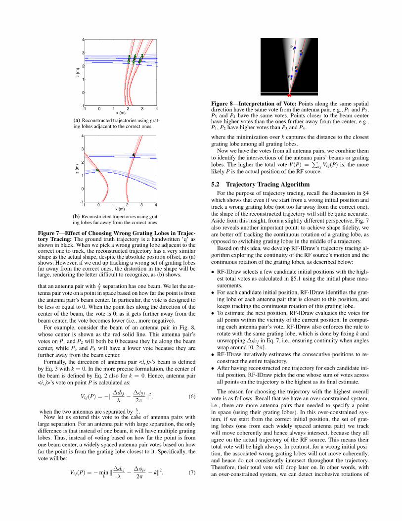
For example, consider the beam of an antenna pair in Fig. 8,whose center is shown as the red solid line. This antenna pair’svotes on P1 and P2 will both be 0 because they lie along the beamcenter, while P3 and P4 will have a lower vote because they arefurther away from the beam center.
Formally, the direction of antenna pair <i, j>’s beam is definedby Eq. 3 with k = 0. In the more precise formulation, the center ofthe beam is defined by Eq. 2 also for k = 0. Hence, antenna pair<i, j>’s vote on point P is calculated as:
Vi,j(P) = −‖∆di,j
λ−
∆φj,i
2π‖2
, (6)
when the two antennas are separated by λ2
.Now let us extend this vote to the case of antenna pairs with
large separation. For an antenna pair with large separation, the onlydifference is that instead of one beam, it will have multiple gratinglobes. Thus, instead of voting based on how far the point is fromone beam center, a widely spaced antenna pair votes based on howfar the point is from the grating lobe closest to it. Specifically, thevote will be:
Vi,j(P) = −mink
‖∆di,j
λ−
∆φj,i
2π− k‖2
, (7)
P4
P3
P1
P2
Figure 8—Interpretation of Vote: Points along the same spatialdirection have the same vote from the antenna pair, e.g., P1 and P2,P3 and P4 have the same votes. Points closer to the beam centerhave higher votes than the ones further away from the center, e.g.,P1, P2 have higher votes than P3 and P4.
where the minimization over k captures the distance to the closestgrating lobe among all grating lobes.
Now we have the votes from all antenna pairs, we combine themto identify the intersections of the antenna pairs’ beams or gratinglobes. The higher the total vote V(P) =
∑i,j Vi,j(P) is, the more
likely P is the actual position of the RF source.
5.2 Trajectory Tracing Algorithm
For the purpose of trajectory tracing, recall the discussion in §4which shows that even if we start from a wrong initial position andtrack a wrong grating lobe (not too far away from the correct one),the shape of the reconstructed trajectory will still be quite accurate.Aside from this insight, from a slightly different perspective, Fig. 7also reveals another important point: to achieve shape fidelity, weare better off tracking the continuous rotation of a grating lobe, asopposed to switching grating lobes in the middle of a trajectory.
Based on this idea, we develop RF-IDraw’s trajectory tracing al-gorithm exploring the continuity of the RF source’s motion and thecontinuous rotation of the grating lobes, as described below:
• RF-IDraw selects a few candidate initial positions with the high-est total votes as calculated in §5.1 using the initial phase mea-surements.
• For each candidate initial position, RF-IDraw identifies the grat-ing lobe of each antenna pair that is closest to this position, andkeeps tracking the continuous rotation of this grating lobe.
• To estimate the next position, RF-IDraw evaluates the votes forall points within the vicinity of the current position. In comput-ing each antenna pair’s vote, RF-IDraw also enforces the rule torotate with the same grating lobe, which is done by fixing k andunwrapping ∆φi,j in Eq. 7, i.e., ensuring continuity when angleswrap around [0, 2π].
• RF-IDraw iteratively estimates the consecutive positions to re-construct the entire trajectory.
• After having reconstructed one trajectory for each candidate ini-tial position, RF-IDraw picks the one whose sum of votes acrossall points on the trajectory is the highest as its final estimate.
The reason for choosing the trajectory with the highest overallvote is as follows. Recall that we have an over-constrained system,i.e., there are more antenna pairs than needed to specify a pointin space (using their grating lobes). In this over-constrained sys-tem, if we start from the correct initial position, the set of grat-ing lobes (one from each widely spaced antenna pair) we trackwill move coherently and hence always intersect, because they allagree on the actual trajectory of the RF source. This means theirtotal vote will be high always. In contrast, for a wrong initial posi-tion, the associated wrong grating lobes will not move coherently,and hence do not consistently intersect throughout the trajectory.Therefore, their total vote will drop later on. In other words, withan over-constrained system, we can detect incohesive rotations of
Figure 9—Commercial UHF RFID Used in Experiments: AlienSquiggle General Purpose UHF RFID
these grating lobes. Thus, by choosing the reconstructed trajectorywith the highest overall trajectory vote, RF-IDraw further refinesthe initial position estimate, as demonstrated in §7.
6. IMPLEMENTATION
We built a prototype of RF-IDraw using commercial off-the-shelfUHF RFID readers to locate and trace the trajectories of EPC Gen-2 [15] UHF RFIDs.
Readers and Software Implementation: We use two ThingMagicM6e 4-port UHF RFID readers [33], each connected with four AN-900LH 900 MHz omni-directional antennas [1]. We program thereaders to continuously query the RFIDs using a carrier frequencyof 922 MHz and return the signal phase for every RFID reply. Weimplemented RF-IDraw’s multi-resolution positioning and trajec-tory tracing algorithms in MATLAB and ran them in real-time.
RFIDs: We use the Alien Squiggle tag [11] shown in Fig. 9, whichis a commercial off-the-shelf passive UHF RFID widely used insupply chain and asset tracking applications. Each of them costs 5-10 cents. We also experimented with the Omni-ID Exo 800 tag [5]to verify RF-IDraw’s design across different types of RFIDs.
Ground Truth: We use the VICON motion capture system [8] tomeasure the ground truth trajectory of the RFID. In a 5×6 m2 roominstrumented with a grid of infrared cameras, the VICON systemcan provide sub-centimeter accuracy in tracking an object taggedwith infrared reflective markers. For experiments in the VICONroom, we measure the ground truth by putting infrared reflectivemarkers on the user’s hand, around the RFID. For experiments out-side the VICON room in an office lounge, we let the user writealong a specific set of trajectories for which the ground truth hasbeen measured manually in advance.
Compared Schemes: We compare RF-IDraw with the state-of-the-art antenna array AoA-based approach [12] using the same numberof antennas as RF-IDraw. In particular, both RF-IDraw and the an-tenna array AoA-based systems employ 8 antennas connected totwo RFID readers. RF-IDraw’s 8 antennas are deployed as shown inFig. 6(d). Since RFIDs communicate by backscattering the readersignal [38], the signal phase reading returned by the reader reflectsthe round trip distance instead of the one-way distance. Hence, eachtightly spaced antenna pair (i.e., <5, 6>, <7, 8>) has a separationof λ
4(as opposed to λ
2) to ensure there is only one beam.3 The
widely spaced antenna pairs (i.e., each edge) have separation of 8λ(i.e., 2.6 m). The antenna array AoA-based scheme uses two an-tenna arrays, each with 4 antennas spaced by λ
4(to account for the
backscattering round trip also). One antenna array is placed alongthe left edge of the square in Fig. 6(d), the other is placed along thebottom edge.
Application Evaluation: We interface RF-IDraw with theMyScript Stylus app [36] on an Android phone using the Mon-keyRunner Android API [4]. This API allows developers to sendspecified sequences of events to an Android device. We use thisAPI to convert the reconstructed trajectory of the RFID to touchscreen input sequences on an Android phone. The MyScript Stylusapp, then, interprets the input as text. We let the users write words
3The equations in this paper apply to the general case of an RFtransmitter. To account for the special case of RFID backscattering,one needs to add a 2 factor to all the ∆dj,i and cos θ in the equations.
randomly sampled from the top 5000 most commonly used wordsin the Corpus of Contemporary American English [6]. Some exam-ples include: "play", "clear", "import", etc. Then, we evaluate thecharacter and word recognition success rates of the reconstructedtrajectories as recognized by the MyScript Stylus app.
7. MICROBENCHMARK
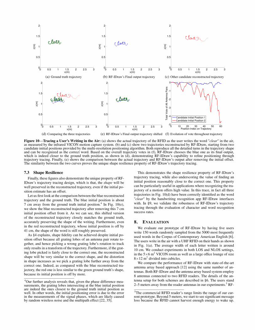
We start with a microbenchmark experiment to provide insightsinto the working of the system. In particular, to better understandthe capabilities and properties of RF-IDraw’s trajectory tracing, welet a user write the word "clear" using the RFID on his hand, in the5×6 m2 VICON room. RF-IDraw uses a total of 8 antennas con-nected to two RFID readers. All reader antennas are deployed ona wall at one side of the VICON room. The user stands 2 m away.Fig. 6 presents the side view of the room, facing the wall of an-tenna deployment. Antenna separations and placement are chosenbased on the application’s needs and room size. Fig. 10(a) showsthe ground truth trajectory of the user’s handwriting measured bythe VICON motion capture system. Now let us see how RF-IDraw’stracing works in practice.
7.1 Granularity of Tracing
In this experiment, RF-IDraw’s multi-resolution positioning al-gorithm (described in §5.1) returned two candidate initial positions.Fig. 10(b) and Fig. 10(c) show the trajectories reconstructed fromthese positions using RF-IDraw’s trajectory tracing algorithm, de-scribed in §5.2. As we can see, RF-IDraw is able to trace everyminute change in the RFID position during the user’s writing. Forexample, the letter ’e’ in the middle is only about 5 cm wide, yetRF-IDraw is able to reproduce the details in its shape by trackingthe rotation of the high-resolution grating lobes.
7.2 Choosing the Correct Initial Position
In order to decide which trajectory to choose out of the two (asthe final output), as §5.2 describes, RF-IDraw looks at the total votefrom all antenna pairs for each position on the trajectory and picksthe trajectory whose overall vote (summing up total votes from allantenna pairs for all positions along the trajectory) is the highest.Fig. 10(f) shows the evolution of the total vote from all antennapairs as the blue and red reconstructed trajectories progress. As wecan see, initially, both the blue and the red have high total votes(i.e., close to 0). That is exactly why their starting points have beenidentified by the multi-resolution positioning algorithm as the can-didate initial positions. However, as the two reconstructed trajec-tories progress, the red one’s total vote quickly drops, significantlydeviating from 0, while the blue one’s vote stays fairly stable andclose to 0, having only occasional deviation. This is because thegrating lobes of the antenna pairs closest to the red initial positiondo not consistently agree throughout the trajectory, leading to nocommon intersection later in the trace, which results in their poortotal vote later on. The detection of this is made possible by theover-constrained system where we have more antenna pairs thanneeded to specify a single point in space, as explained in §5.2.
Comparing the overall votes throughout the trajectories, RF-IDraw picks the blue trajectory as its final output. Fig. 10(d) showsthe ground truth, RF-IDraw’s final output, and the red trajectory onthe same plot. As we can see, the blue trajectory which RF-IDrawpicks indeed better matches the ground truth than the red one, andthe blue initial position is also closer to the ground truth than thered candidate. This demonstrates RF-IDraw’s power in leveragingits trajectory tracing to further refine its positioning.
0 0.5 1 1.5 2 2.5 30
0.5
1
1.5
2
x(m)
z(m
)
(a) Ground truth trajectory
0 0.5 1 1.5 2 2.5 30
0.5
1
1.5
2
x(m)
z(m
)
(b) RF-IDraw’s Final output trajectory
0 0.5 1 1.5 2 2.5 30
0.5
1
1.5
2
x(m)
z(m
)
(c) Other candidate reconstructed trajectory
0 0.5 1 1.5 2 2.5 30
0.5
1
1.5
2
x(m)
z(m
)
(d) Comparing the three trajectories
0 0.5 1 1.5 2 2.5 30
0.5
1
1.5
2
x(m)
z(m
)
(e) RF-IDraw’s Final output trajectory shifted
0 10 20 30 40 50 60-5
-4
-3
-2
-1
0
Position Index on Trajectory
To
tal V
ote
of
All
An
ten
na
Pa
irs
Candidate Initial Position 1
Candidate Initial Position 2
(f) Evolution of vote throughout trajectory
Figure 10—Tracing a User’s Writing in the Air: (a) shows the actual trajectory of the RFID as the user writes the word "clear" in the air,as measured by the infrared VICON motion capture system. (b) and (c) show two trajectories reconstructed by RF-IDraw, starting from twocandidate initial positions provided by the multi-resolution positioning algorithm. Both reproduce all the detailed turns in the trajectory shapeand can be recognized as the correct word. Based on the overall trajectory votes in (f), RF-IDraw chooses the blue one as its final output,which is indeed closer to the ground truth position, as shown in (d), demonstrating RF-IDraw’s capability to refine positioning throughtrajectory tracing. Finally, (e) shows the comparison between the actual trajectory and RF-IDraw’s output after removing the initial offset.The similarity between the two curves proves the unique shape resilience property of RF-IDraw’s trajectory tracing.
7.3 Shape Resilience
Finally, these figures also demonstrate the unique property of RF-IDraw’s trajectory tracing design, which is that, the shape will bewell preserved in the reconstructed trajectory, even if the initial po-sition estimate has an offset.
Let us first look at the comparison between the blue reconstructedtrajectory and the ground truth. The blue initial position is about7 cm away from the ground truth initial position.4 In Fig. 10(e),we show the blue reconstructed trajectory after removing this 7 cminitial position offset from it. As we can see, this shifted versionof the reconstructed trajectory closely matches the ground truth,accurately preserving the shape of the writing. Furthermore, evenin the red reconstructed trajectory, whose initial position is off by41 cm, the shape of the word is still roughly preserved.
As §4 explains, shape fidelity can be achieved despite initial po-sition offset because all grating lobes of an antenna pair rotate to-gether, and hence picking a wrong grating lobe’s rotation to trackonly results in a transform of the trajectory. Furthermore, if the grat-ing lobe picked is fairly close to the correct one, the reconstructedshape will be very similar to the correct shape, and the distortionin shape increases as we pick a grating lobe further away from thecorrect one. Indeed, as compared with the blue reconstructed tra-jectory, the red one is less similar to the green ground truth’s shape,because its initial position is off by more.
4Our further analysis reveals that, given the phase difference mea-surements, the grating lobes intersecting at the blue initial positionare indeed the ones closest to the ground truth initial position aswell. In other words, the initial positioning error is due to the errorin the measurements of the signal phases, which are likely causedby random wireless noise and the multipath effect [22, 35].
This demonstrates the shape resilience property of RF-IDraw’strajectory tracing, while also underscoring the value of finding aninitial position reasonably close to the correct one. This propertycan be particularly useful in applications where recognizing the tra-jectory of a motion offers high value. In this trace, in fact all threetrajectories in Fig. 10(d) have been correctly identified as the word"clear" by the handwriting recognition app RF-IDraw interfaceswith. In §9, we validate the robustness of RF-IDraw’s trajectorytracing through the evaluation of character and word recognitionsuccess rates.
8. EVALUATION
We evaluate our prototype of RF-IDraw by having five userswrite 150 words randomly sampled from the 5000 most frequentlyused words in the Corpus of Contemporary American English [6].The users write in the air with a UHF RFID on their hands as shownin Fig. 1(a). The average width of each letter written is around10 cm. We conduct experiments in both LOS and NLOS settings,in the 5×6 m2 VICON room as well as a large office lounge of size8×12 m2 divided into cubicles.
We compare the performance of RF-IDraw with state-of-the-artantenna array based approach [12] using the same number of an-tennas. Both RF-IDraw and the antenna array based system employ8 antennas connected to two RFID readers. The details of the an-tenna setup for both schemes are described in §6. The users stand2–5 meters away from the reader antennas in our experiments.5 RF-
5The commercial RFID reader’s range limits the range of our cur-rent prototype. Beyond 5 meters, we start to see significant messageloss because the RFID cannot harvest enough energy to wake up.
1 10 100 10000
0.2
0.4
0.6
0.8
1
Trajectory Error (cm)
CD
FRF-IDraw
Antenna Arrays
(a) CDF of Trajectory Error Distance in LOS
1 10 100 10000
0.2
0.4
0.6
0.8
1
Trajectory Error (cm)
CD
F
RF-IDraw
Antenna Arrays
(b) CDF of Trajectory Error Distance in NLOS
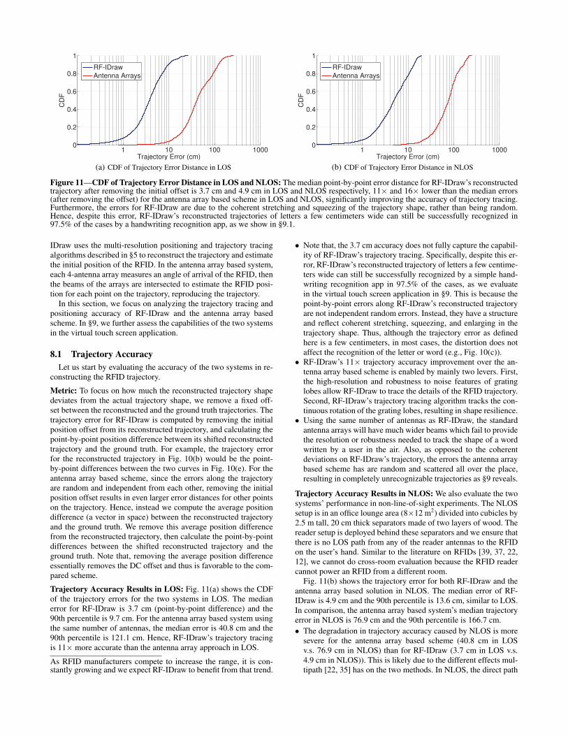
Figure 11—CDF of Trajectory Error Distance in LOS and NLOS: The median point-by-point error distance for RF-IDraw’s reconstructedtrajectory after removing the initial offset is 3.7 cm and 4.9 cm in LOS and NLOS respectively, 11× and 16× lower than the median errors(after removing the offset) for the antenna array based scheme in LOS and NLOS, significantly improving the accuracy of trajectory tracing.Furthermore, the errors for RF-IDraw are due to the coherent stretching and squeezing of the trajectory shape, rather than being random.Hence, despite this error, RF-IDraw’s reconstructed trajectories of letters a few centimeters wide can still be successfully recognized in97.5% of the cases by a handwriting recognition app, as we show in §9.1.
IDraw uses the multi-resolution positioning and trajectory tracingalgorithms described in §5 to reconstruct the trajectory and estimatethe initial position of the RFID. In the antenna array based system,each 4-antenna array measures an angle of arrival of the RFID, thenthe beams of the arrays are intersected to estimate the RFID posi-tion for each point on the trajectory, reproducing the trajectory.
In this section, we focus on analyzing the trajectory tracing andpositioning accuracy of RF-IDraw and the antenna array basedscheme. In §9, we further assess the capabilities of the two systemsin the virtual touch screen application.
8.1 Trajectory Accuracy
Let us start by evaluating the accuracy of the two systems in re-constructing the RFID trajectory.
Metric: To focus on how much the reconstructed trajectory shapedeviates from the actual trajectory shape, we remove a fixed off-set between the reconstructed and the ground truth trajectories. Thetrajectory error for RF-IDraw is computed by removing the initialposition offset from its reconstructed trajectory, and calculating thepoint-by-point position difference between its shifted reconstructedtrajectory and the ground truth. For example, the trajectory errorfor the reconstructed trajectory in Fig. 10(b) would be the point-by-point differences between the two curves in Fig. 10(e). For theantenna array based scheme, since the errors along the trajectoryare random and independent from each other, removing the initialposition offset results in even larger error distances for other pointson the trajectory. Hence, instead we compute the average positiondifference (a vector in space) between the reconstructed trajectoryand the ground truth. We remove this average position differencefrom the reconstructed trajectory, then calculate the point-by-pointdifferences between the shifted reconstructed trajectory and theground truth. Note that, removing the average position differenceessentially removes the DC offset and thus is favorable to the com-pared scheme.
Trajectory Accuracy Results in LOS: Fig. 11(a) shows the CDFof the trajectory errors for the two systems in LOS. The medianerror for RF-IDraw is 3.7 cm (point-by-point difference) and the90th percentile is 9.7 cm. For the antenna array based system usingthe same number of antennas, the median error is 40.8 cm and the90th percentile is 121.1 cm. Hence, RF-IDraw’s trajectory tracingis 11× more accurate than the antenna array approach in LOS.
As RFID manufacturers compete to increase the range, it is con-stantly growing and we expect RF-IDraw to benefit from that trend.
• Note that, the 3.7 cm accuracy does not fully capture the capabil-ity of RF-IDraw’s trajectory tracing. Specifically, despite this er-ror, RF-IDraw’s reconstructed trajectory of letters a few centime-ters wide can still be successfully recognized by a simple hand-writing recognition app in 97.5% of the cases, as we evaluatein the virtual touch screen application in §9. This is because thepoint-by-point errors along RF-IDraw’s reconstructed trajectoryare not independent random errors. Instead, they have a structureand reflect coherent stretching, squeezing, and enlarging in thetrajectory shape. Thus, although the trajectory error as definedhere is a few centimeters, in most cases, the distortion does notaffect the recognition of the letter or word (e.g., Fig. 10(c)).
• RF-IDraw’s 11× trajectory accuracy improvement over the an-tenna array based scheme is enabled by mainly two levers. First,the high-resolution and robustness to noise features of gratinglobes allow RF-IDraw to trace the details of the RFID trajectory.Second, RF-IDraw’s trajectory tracing algorithm tracks the con-tinuous rotation of the grating lobes, resulting in shape resilience.
• Using the same number of antennas as RF-IDraw, the standardantenna arrays will have much wider beams which fail to providethe resolution or robustness needed to track the shape of a wordwritten by a user in the air. Also, as opposed to the coherentdeviations on RF-IDraw’s trajectory, the errors the antenna arraybased scheme has are random and scattered all over the place,resulting in completely unrecognizable trajectories as §9 reveals.
Trajectory Accuracy Results in NLOS: We also evaluate the twosystems’ performance in non-line-of-sight experiments. The NLOSsetup is in an office lounge area (8×12 m2) divided into cubicles by2.5 m tall, 20 cm thick separators made of two layers of wood. Thereader setup is deployed behind these separators and we ensure thatthere is no LOS path from any of the reader antennas to the RFIDon the user’s hand. Similar to the literature on RFIDs [39, 37, 22,12], we cannot do cross-room evaluation because the RFID readercannot power an RFID from a different room.
Fig. 11(b) shows the trajectory error for both RF-IDraw and theantenna array based solution in NLOS. The median error of RF-IDraw is 4.9 cm and the 90th percentile is 13.6 cm, similar to LOS.In comparison, the antenna array based system’s median trajectoryerror in NLOS is 76.9 cm and the 90th percentile is 166.7 cm.
• The degradation in trajectory accuracy caused by NLOS is moresevere for the antenna array based scheme (40.8 cm in LOSv.s. 76.9 cm in NLOS) than for RF-IDraw (3.7 cm in LOS v.s.4.9 cm in NLOS)). This is likely due to the different effects mul-tipath [22, 35] has on the two methods. In NLOS, the direct path
1 10 100 10000
0.2
0.4
0.6
0.8
1
Initial Position Error (cm)
CD
FRF-IDraw
Antenna Arrays
(a) CDF of Initial Position Error Distance in LOS
1 10 100 10000
0.2
0.4
0.6
0.8
1
Initial Position Error (cm)
CD
F
RF-IDraw
Antenna Arrays
(b) CDF of Initial Position Error Distance in NLOS
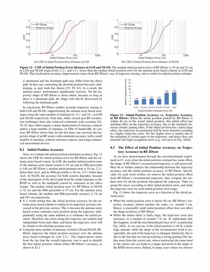
Figure 12—CDF of Initial Position Error Distance in LOS and NLOS: The median initial position error of RF-IDraw is 19 cm and 32 cmin LOS and NLOS respectively, 2.2× and 2.3× lower than the median initial position error for the antenna array based scheme in LOS andNLOS. This localization accuracy improvement comes from RF-IDraw’s use of trajectory tracing votes to refine its initial position estimate.
is attenuated and the dominant path may differ from the directpath. In this case, estimating the absolute position becomes chal-lenging, as past work has shown [19, 39, 41]. As a result, theantenna arrays’ performance significantly worsens. Yet the tra-jectory shape of RF-IDraw is more robust, because as long asthere is a dominant path, the shape will still be discovered byfollowing the dominant path.
In conclusion, RF-IDraw enables accurate trajectory tracing inboth LOS and NLOS, outperforming the antenna array based tech-nique using the same number of antennas by 11× and 16× in LOSand NLOS respectively. Note that, while several past RF localiza-tion techniques have also achieved centimeter scale accuracy [41,39, 9], they either require a dense deployment of reference sourcesand/or a large number of antennas, or GHz of bandwidth. In con-trast, RF-IDraw shows that, for the first time, one can trace the tra-jectory shape of an RF source with centimeter accuracy with a smallnumber of antennas, without reference sources, and using commer-cial narrowband devices.
8.2 Initial Position Accuracy
Next, we evaluate the initial position estimation accuracy. Fig. 12shows the CDF for initial position error for RF-IDraw and the an-tenna array based system. In LOS, the median initial position errorof the antenna array based system is 42 cm and its 90th percentileis 148 cm; RF-IDraw’s median initial position error is 19 cm, 2.2×better than AoA, and its 90th percentile is 38 cm, 3.9× better thanAoA. In NLOS, the accuracy for both systems degrades, becauseof the attenuation of the direct path from the reader antennas to theRFID as well as the multipath caused by structures in the officelounge. The median initial position error for RF-IDraw in NLOSis 32 cm and the 90th percentile is 47 cm. For the antenna arraybased scheme, the median and 90th percentile accuracy is 74 cmand 183 cm respectively.• It is worth noting that, the initial position accuracy for the an-
tenna array based scheme is similar to its trajectory accuracy dis-cussed in the previous section. This is because the antenna arraybased system estimates each position along the trajectory inde-pendently using the same method as it estimates the initial po-sition. Therefore, the errors along the trajectory are random andindependent from each other, and hence the trajectory error willbe similar to the absolute position error.
• Using the same number of antennas, in both LOS and NLOS, RF-IDraw improves the initial position accuracy over the antennaarray based technique by over 2.2×. This improvement stemsfrom the fact that the overall trajectory vote is used to identifythe best initial position, which refines RF-IDraw’s accuracy, asshown in §7.2.
2.863.64 3.9 3.67
7.62 7.91
0
2
4
6
8
10
12
14
16
0‐0.1 0.1‐0.2 0.2‐0.3 0.3‐0.4 0.4‐0.5 >0.5
Initial Position Estimate Error (m)
Median
Trajectory
Error (cm
)
Figure 13—Initial Position Accuracy v.s. Trajectory Accuracyin RF-IDraw: When the initial position picked by RF-IDraw iswithin 40 cm of the actual initial position, this initial offset hasminimal effect on the trajectory accuracy, due to the similarity be-tween closeby grating lobes. If the initial position has a fairly largeoffset, the trajectory reconstructed will be more distorted, resultingin a higher trajectory error. Yet this higher error is mainly due tothe enlarging of certain parts in the trajectory, and hence does nottranslate into high recognition error (e.g., red curve in Fig. 10(d)).
8.3 The Effect of Initial Position Accuracy on Trajec-
tory Accuracy in RF-IDraw
As we have demonstrated through the microbenchmark experi-ment in §7, even when the initial position estimate has some offset,the shape of RF-IDraw’s reconstructed trajectory is still preserved.Here let us further analyze the relationship between the trajectoryaccuracy and the initial position accuracy of RF-IDraw. Specifi-cally, for each word written, we remove the initial position offsetfrom RF-IDraw’s reconstructed trajectory, then compute the me-dian error for all the positions throughout the trajectory. Then wegroup the traces according to their initial position error, and studythe trajectory error for each initial position error range.
Fig. 13 shows the trajectory error as a function of the initial po-sition error.
• When the initial position error is below 40 cm, RF-IDraw’s tra-jectory accuracy almost remains the same, i.e., around 3 cm.Hence, a reasonably small initial position offset does not affectthe shape resilience of RF-IDraw.
• When the initial offset is fairly large, the trajectory error alsoincreases, to a median of around 7–8 cm. To understand whythis happens, recall the microbenchmark trace in §7, in particularFig. 10(d). As we can see, if the initial position is off by a fairlylarge amount, while the shape of the reconstructed word is rec-ognizable, the end of the trajectory is enlarged. Intuitively, this isdue to the fact that we end up tracking a wrong grating lobe fur-ther away from the correct one, whose motion has the same trendas the correct one yet leads to a larger distortion in the shape asthe RFID moves more. Indeed, in many cases where we observe
98.0% 97.6% 97.3%
4.2% 3.7% 0.4%0%
20%
40%
60%
80%
100%
2m 3m 5m
Distance from User to Reader Antennas
CharacterSuccess
Rate
RF‐IDraw
Antenna Arrays
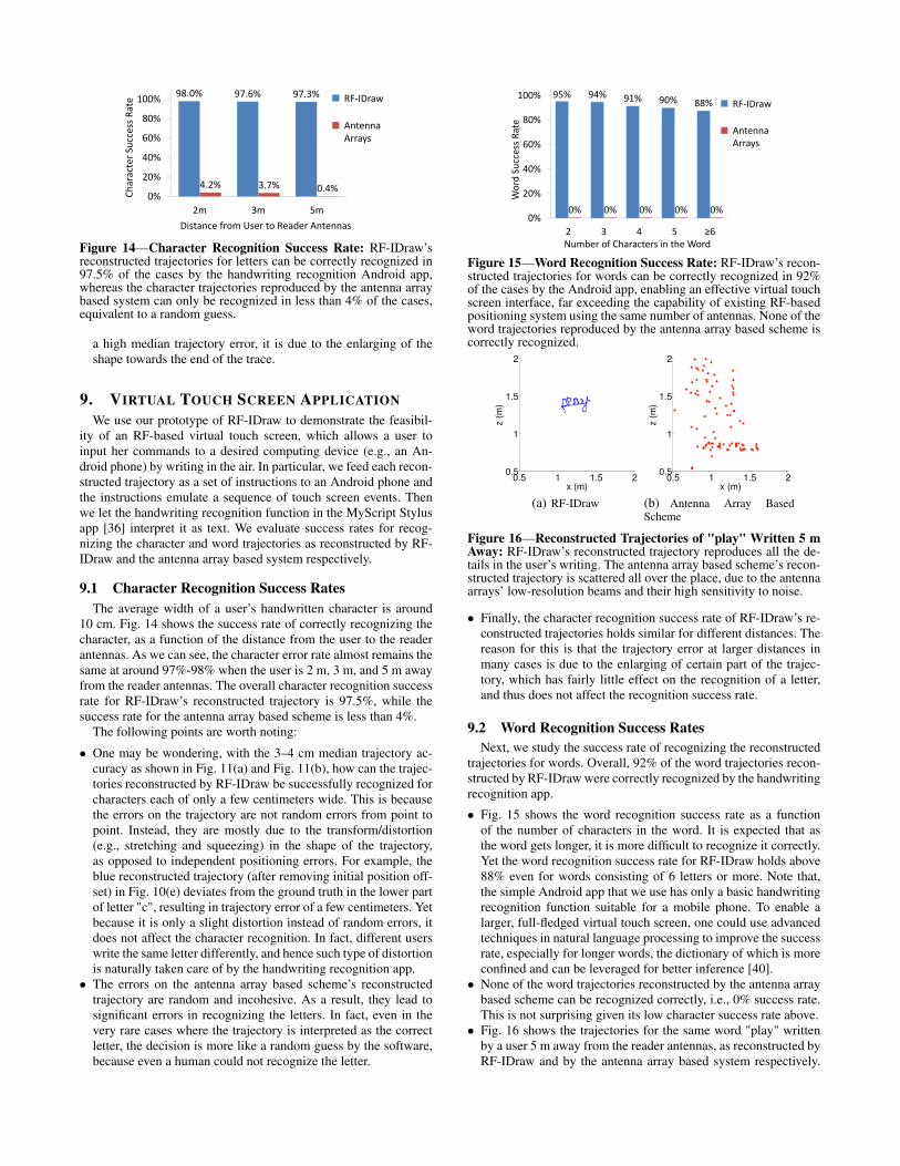
Figure 14—Character Recognition Success Rate: RF-IDraw’sreconstructed trajectories for letters can be correctly recognized in97.5% of the cases by the handwriting recognition Android app,whereas the character trajectories reproduced by the antenna arraybased system can only be recognized in less than 4% of the cases,equivalent to a random guess.
a high median trajectory error, it is due to the enlarging of theshape towards the end of the trace.
9. VIRTUAL TOUCH SCREEN APPLICATION
We use our prototype of RF-IDraw to demonstrate the feasibil-ity of an RF-based virtual touch screen, which allows a user toinput her commands to a desired computing device (e.g., an An-droid phone) by writing in the air. In particular, we feed each recon-structed trajectory as a set of instructions to an Android phone andthe instructions emulate a sequence of touch screen events. Thenwe let the handwriting recognition function in the MyScript Stylusapp [36] interpret it as text. We evaluate success rates for recog-nizing the character and word trajectories as reconstructed by RF-IDraw and the antenna array based system respectively.
9.1 Character Recognition Success Rates
The average width of a user’s handwritten character is around10 cm. Fig. 14 shows the success rate of correctly recognizing thecharacter, as a function of the distance from the user to the readerantennas. As we can see, the character error rate almost remains thesame at around 97%-98% when the user is 2 m, 3 m, and 5 m awayfrom the reader antennas. The overall character recognition successrate for RF-IDraw’s reconstructed trajectory is 97.5%, while thesuccess rate for the antenna array based scheme is less than 4%.
The following points are worth noting:
• One may be wondering, with the 3–4 cm median trajectory ac-curacy as shown in Fig. 11(a) and Fig. 11(b), how can the trajec-tories reconstructed by RF-IDraw be successfully recognized forcharacters each of only a few centimeters wide. This is becausethe errors on the trajectory are not random errors from point topoint. Instead, they are mostly due to the transform/distortion(e.g., stretching and squeezing) in the shape of the trajectory,as opposed to independent positioning errors. For example, theblue reconstructed trajectory (after removing initial position off-set) in Fig. 10(e) deviates from the ground truth in the lower partof letter "c", resulting in trajectory error of a few centimeters. Yetbecause it is only a slight distortion instead of random errors, itdoes not affect the character recognition. In fact, different userswrite the same letter differently, and hence such type of distortionis naturally taken care of by the handwriting recognition app.
• The errors on the antenna array based scheme’s reconstructedtrajectory are random and incohesive. As a result, they lead tosignificant errors in recognizing the letters. In fact, even in thevery rare cases where the trajectory is interpreted as the correctletter, the decision is more like a random guess by the software,because even a human could not recognize the letter.
95% 94% 91% 90% 88%
0% 0% 0% 0% 0%0%
20%
40%
60%
80%
100%
2 3 4 5 ≥6
Word
Success
Rate
Number of Characters in the Word
RF‐IDraw
Antenna Arrays
Figure 15—Word Recognition Success Rate: RF-IDraw’s recon-structed trajectories for words can be correctly recognized in 92%of the cases by the Android app, enabling an effective virtual touchscreen interface, far exceeding the capability of existing RF-basedpositioning system using the same number of antennas. None of theword trajectories reproduced by the antenna array based scheme iscorrectly recognized.
0.5 1 1.5 20.5
1
1.5
2
x (m)
z (
m)
(a) RF-IDraw
0.5 1 1.5 20.5
1
1.5
2
x (m)
z (
m)
(b) Antenna Array BasedScheme
Figure 16—Reconstructed Trajectories of "play" Written 5 mAway: RF-IDraw’s reconstructed trajectory reproduces all the de-tails in the user’s writing. The antenna array based scheme’s recon-structed trajectory is scattered all over the place, due to the antennaarrays’ low-resolution beams and their high sensitivity to noise.
• Finally, the character recognition success rate of RF-IDraw’s re-constructed trajectories holds similar for different distances. Thereason for this is that the trajectory error at larger distances inmany cases is due to the enlarging of certain part of the trajec-tory, which has fairly little effect on the recognition of a letter,and thus does not affect the recognition success rate.
9.2 Word Recognition Success Rates
Next, we study the success rate of recognizing the reconstructedtrajectories for words. Overall, 92% of the word trajectories recon-structed by RF-IDraw were correctly recognized by the handwritingrecognition app.
• Fig. 15 shows the word recognition success rate as a functionof the number of characters in the word. It is expected that asthe word gets longer, it is more difficult to recognize it correctly.Yet the word recognition success rate for RF-IDraw holds above88% even for words consisting of 6 letters or more. Note that,the simple Android app that we use has only a basic handwritingrecognition function suitable for a mobile phone. To enable alarger, full-fledged virtual touch screen, one could use advancedtechniques in natural language processing to improve the successrate, especially for longer words, the dictionary of which is moreconfined and can be leveraged for better inference [40].
• None of the word trajectories reconstructed by the antenna arraybased scheme can be recognized correctly, i.e., 0% success rate.This is not surprising given its low character success rate above.
• Fig. 16 shows the trajectories for the same word "play" writtenby a user 5 m away from the reader antennas, as reconstructed byRF-IDraw and by the antenna array based system respectively.
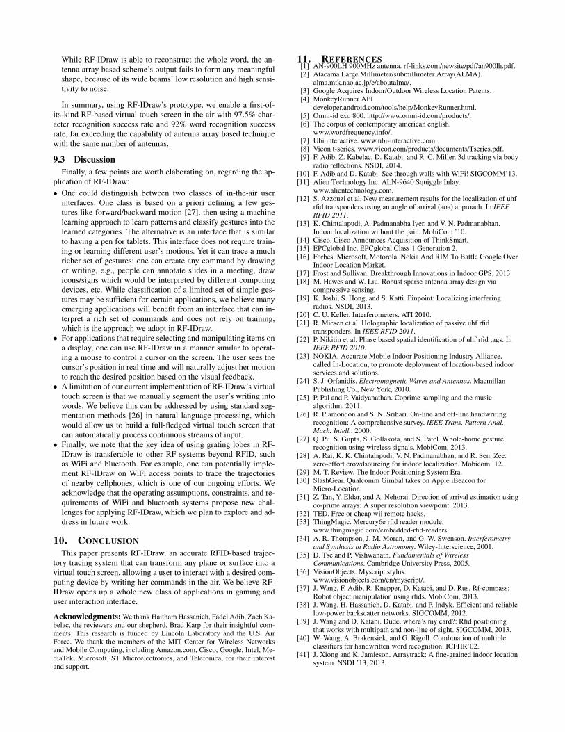
While RF-IDraw is able to reconstruct the whole word, the an-tenna array based scheme’s output fails to form any meaningfulshape, because of its wide beams’ low resolution and high sensi-tivity to noise.
In summary, using RF-IDraw’s prototype, we enable a first-of-its-kind RF-based virtual touch screen in the air with 97.5% char-acter recognition success rate and 92% word recognition successrate, far exceeding the capability of antenna array based techniquewith the same number of antennas.
9.3 Discussion
Finally, a few points are worth elaborating on, regarding the ap-plication of RF-IDraw:
• One could distinguish between two classes of in-the-air userinterfaces. One class is based on a priori defining a few ges-tures like forward/backward motion [27], then using a machinelearning approach to learn patterns and classify gestures into thelearned categories. The alternative is an interface that is similarto having a pen for tablets. This interface does not require train-ing or learning different user’s motions. Yet it can trace a muchricher set of gestures: one can create any command by drawingor writing, e.g., people can annotate slides in a meeting, drawicons/signs which would be interpreted by different computingdevices, etc. While classification of a limited set of simple ges-tures may be sufficient for certain applications, we believe manyemerging applications will benefit from an interface that can in-terpret a rich set of commands and does not rely on training,which is the approach we adopt in RF-IDraw.
• For applications that require selecting and manipulating items ona display, one can use RF-IDraw in a manner similar to operat-ing a mouse to control a cursor on the screen. The user sees thecursor’s position in real time and will naturally adjust her motionto reach the desired position based on the visual feedback.
• A limitation of our current implementation of RF-IDraw’s virtualtouch screen is that we manually segment the user’s writing intowords. We believe this can be addressed by using standard seg-mentation methods [26] in natural language processing, whichwould allow us to build a full-fledged virtual touch screen thatcan automatically process continuous streams of input.
• Finally, we note that the key idea of using grating lobes in RF-IDraw is transferable to other RF systems beyond RFID, suchas WiFi and bluetooth. For example, one can potentially imple-ment RF-IDraw on WiFi access points to trace the trajectoriesof nearby cellphones, which is one of our ongoing efforts. Weacknowledge that the operating assumptions, constraints, and re-quirements of WiFi and bluetooth systems propose new chal-lenges for applying RF-IDraw, which we plan to explore and ad-dress in future work.
10. CONCLUSION
This paper presents RF-IDraw, an accurate RFID-based trajec-tory tracing system that can transform any plane or surface into avirtual touch screen, allowing a user to interact with a desired com-puting device by writing her commands in the air. We believe RF-IDraw opens up a whole new class of applications in gaming anduser interaction interface.
Acknowledgments: We thank Haitham Hassanieh, Fadel Adib, Zach Ka-belac, the reviewers and our shepherd, Brad Karp for their insightful com-ments. This research is funded by Lincoln Laboratory and the U.S. AirForce. We thank the members of the MIT Center for Wireless Networksand Mobile Computing, including Amazon.com, Cisco, Google, Intel, Me-diaTek, Microsoft, ST Microelectronics, and Telefonica, for their interestand support.
11. REFERENCES[1] AN-900LH 900MHz antenna. rf-links.com/newsite/pdf/an900lh.pdf.[2] Atacama Large Millimeter/submillimeter Array(ALMA).
alma.mtk.nao.ac.jp/e/aboutalma/.[3] Google Acquires Indoor/Outdoor Wireless Location Patents.[4] MonkeyRunner API.
developer.android.com/tools/help/MonkeyRunner.html.[5] Omni-id exo 800. http://www.omni-id.com/products/.[6] The corpus of contemporary american english.
www.wordfrequency.info/.[7] Ubi interactive. www.ubi-interactive.com.[8] Vicon t-series. www.vicon.com/products/documents/Tseries.pdf.[9] F. Adib, Z. Kabelac, D. Katabi, and R. C. Miller. 3d tracking via body
radio reflections. NSDI, 2014.[10] F. Adib and D. Katabi. See through walls with WiFi! SIGCOMM’13.[11] Alien Technology Inc. ALN-9640 Squiggle Inlay.
www.alientechnology.com.[12] S. Azzouzi et al. New measurement results for the localization of uhf
rfid transponders using an angle of arrival (aoa) approach. In IEEE
RFID 2011.[13] K. Chintalapudi, A. Padmanabha Iyer, and V. N. Padmanabhan.
Indoor localization without the pain. MobiCom ’10.[14] Cisco. Cisco Announces Acquisition of ThinkSmart.[15] EPCglobal Inc. EPCglobal Class 1 Generation 2.[16] Forbes. Microsoft, Motorola, Nokia And RIM To Battle Google Over
Indoor Location Market.[17] Frost and Sullivan. Breakthrough Innovations in Indoor GPS, 2013.[18] M. Hawes and W. Liu. Robust sparse antenna array design via
compressive sensing.[19] K. Joshi, S. Hong, and S. Katti. Pinpoint: Localizing interfering
radios. NSDI, 2013.[20] C. U. Keller. Interferometers. ATI 2010.[21] R. Miesen et al. Holographic localization of passive uhf rfid
transponders. In IEEE RFID 2011.[22] P. Nikitin et al. Phase based spatial identification of uhf rfid tags. In
IEEE RFID 2010.[23] NOKIA. Accurate Mobile Indoor Positioning Industry Alliance,
called In-Location, to promote deployment of location-based indoorservices and solutions.
[24] S. J. Orfanidis. Electromagnetic Waves and Antennas. MacmillanPublishing Co., New York, 2010.
[25] P. Pal and P. Vaidyanathan. Coprime sampling and the musicalgorithm. 2011.
[26] R. Plamondon and S. N. Srihari. On-line and off-line handwritingrecognition: A comprehensive survey. IEEE Trans. Pattern Anal.
Mach. Intell., 2000.[27] Q. Pu, S. Gupta, S. Gollakota, and S. Patel. Whole-home gesture
recognition using wireless signals. MobiCom, 2013.[28] A. Rai, K. K. Chintalapudi, V. N. Padmanabhan, and R. Sen. Zee:
zero-effort crowdsourcing for indoor localization. Mobicom ’12.[29] M. T. Review. The Indoor Positioning System Era.[30] SlashGear. Qualcomm Gimbal takes on Apple iBeacon for
Micro-Location.[31] Z. Tan, Y. Eldar, and A. Nehorai. Direction of arrival estimation using
co-prime arrays: A super resolution viewpoint. 2013.[32] TED. Free or cheap wii remote hacks.[33] ThingMagic. Mercury6e rfid reader module.
www.thingmagic.com/embedded-rfid-readers.[34] A. R. Thompson, J. M. Moran, and G. W. Swenson. Interferometry
and Synthesis in Radio Astronomy. Wiley-Interscience, 2001.[35] D. Tse and P. Vishwanath. Fundamentals of Wireless
Communications. Cambridge University Press, 2005.[36] VisionObjects. Myscript stylus.
www.visionobjects.com/en/myscript/.[37] J. Wang, F. Adib, R. Knepper, D. Katabi, and D. Rus. Rf-compass:
Robot object manipulation using rfids. MobiCom, 2013.[38] J. Wang, H. Hassanieh, D. Katabi, and P. Indyk. Efficient and reliable
low-power backscatter networks. SIGCOMM, 2012.[39] J. Wang and D. Katabi. Dude, where’s my card?: Rfid positioning
that works with multipath and non-line of sight. SIGCOMM, 2013.[40] W. Wang, A. Brakensiek, and G. Rigoll. Combination of multiple
classifiers for handwritten word recognition. ICFHR’02.[41] J. Xiong and K. Jamieson. Arraytrack: A fine-grained indoor location
system. NSDI ’13, 2013.