Embed Size (px)
Citation preview

RF DESIGN TOOL FOR END-TO-END OPTIMISATION OF HIGH-PERFORMANCEMULTIBEAM ANTENNA SYSTEMS
Erik Jørgensen(1), Niels Vesterdal(1), Min Zhou(1), Peter Meincke(1), Oscar Borries(1), Michael F.Palvig(1), Tonny Rubæk(1), Massimiliano Simeoni(2), Giovanni Toso(2)
(1)TICRA, Landemærket 29, 5., DK-1119 Copenhagen K, Denmark, Email:{ej,nvl,mz,pme,ob,mfp,tr}@ticra.com
(2)ESA-ESTEC, Keplerlaan 1, 2200 AG Noordwijk, The Netherlands, Email:[email protected], [email protected]
Abstract—This paper describes a new integrated RFdesign tool for analysis and optimisation of reflector-based multibeam antenna systems. The new tool com-bines several powerful algorithms into a flexible soft-ware framework that allows end-to-end optimisationof antenna systems comprising of passive microwavecomponents, feed horns, reflectors, and advanced surfacessuch as reflectarrays, transmitarrays, or frequency andpolarisation selective surfaces. The term end-to-end isused to indicate that the entire multibeam system can beoptimised as one model where only the final performanceparameters of the complete antenna system are included,e.g., the return loss at the input ports of the first feedchain components and the resulting beam shapes after thelast reflecting surface. We illustrate the new capabilitieswith design examples, e.g., a single-feed-per-beam feedcluster that is directly optimised for improved C/I ratioof the beams radiated by the main reflector.
I. INTRODUCTION
High-Performance multibeam antennas for space ap-plications are often realized using a reflector systemin which a large number of feeds are illuminating areflecting surface that generates a multitude of focusedbeams. The feed system may use a single feed perbeam configuration or a multiple feed per beam config-uration and in both cases each feed is typically realizedas a smooth-walled or corrugated horn in conjunc-tion with several passive microwave components, e.g.,polarizers, orthomode junctions, or filters. Significantresearch efforts have recently been devoted to furtherenhance multibeam antenna performance by utilizingadvanced concepts in which one or more reflectorsare replaced with a periodic or quasi-periodic surface,e.g., frequency or polarization selective surfaces, re-flectarrays, or transmitarrays. In all the aforementionedcases, the RF design of the microwave components,the feed, the reflector, or the periodic surface, is typ-ically performed using separate high-end optimisationtools dedicated to a specific purpose. Consequently,each antenna subsystem is optimised separately whichimplies that subsystem requirements must be derivedand expressed in terms of intermediate performanceparameters that are not performance parameters of theoverall antenna system. This approach where optimi-sation is applied at the subsystem level is known as an
indirect optimisation, because there is no direct relationbetween the variables being optimised, e.g., the feedgeometry, and the actual performance parameters ofinterest, e.g., the beam shape produced by the reflector.Efficient RF design tools are available at the subsystemlevel while tool limitations imply that an end-to-endRF model encompassing all antenna subsystems isoften not feasible or the analysis time is far too time-consuming to allow optimisation.
The present paper describes two recently completedRF design tool developments performed within ESA’sARTES framework [1], [2]. The combination of thesetwo developments and the industry’s standard tool forreflector analysis, GRASP, provides a single powerfulRF design tool that allows an end-to-end model tobe defined, analyzed, and optimised. The model mayinclude passive microwave components, feed horns,and any number of reflecting surfaces, including solidreflectors, frequency- or polarization-selective surfaces,reflectarrays, or transmitarrays. All geometrical pa-rameters included in the model may be optimised,e.g., the dimensions of arbitrarily shaped waveguidecomponents, horn profiles, reflectors shapes, or thegeometrical parameters of the individual periodic el-ement in a reflectarray. In addition to the traditionalindirect optimisation at the subsystem level, the newtool also supports a direct optimisation approach wherethe performance is only evaluated on the final antennaparameters of interest, e.g., the reflection level at thefirst waveguide component in the feed chain and the di-rectivity of the beams radiated by the last reflecting sur-face. Intermediate parameters, such as the feed taper,are left unspecified because these are not performanceparameters of the overall antenna system. Furthermore,the tool allows all beams in a multibeam system to beoptimised simultaneously which implies that importantperformance parameters involving multiple beams, e.g.,the C/I ratio, can be directly optimised.
The paper is organised as follows. Section II de-scribes the new integrated software tool for feed chainsand Section III describes the new integrated softwaretool for periodic and quasi-periodic surfaces. Finally,multibeam design examples will be presented in Sec-tion IV.
39th ESA Antenna Workshop on Innovative Antenna Systems and Technologies for Future Space Missions02-04 October 2018, Noordwijk, The Netherlands
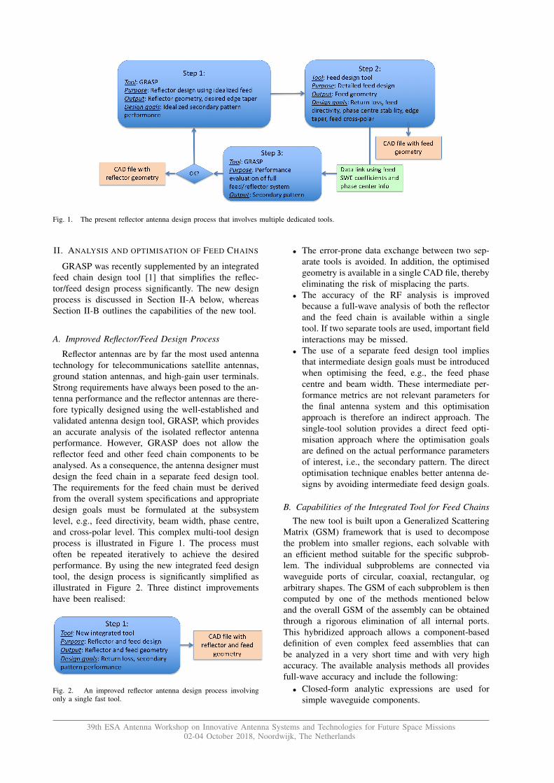
Fig. 1. The present reflector antenna design process that involves multiple dedicated tools.
II. ANALYSIS AND OPTIMISATION OF FEED CHAINS
GRASP was recently supplemented by an integratedfeed chain design tool [1] that simplifies the reflec-tor/feed design process significantly. The new designprocess is discussed in Section II-A below, whereasSection II-B outlines the capabilities of the new tool.
A. Improved Reflector/Feed Design Process
Reflector antennas are by far the most used antennatechnology for telecommunications satellite antennas,ground station antennas, and high-gain user terminals.Strong requirements have always been posed to the an-tenna performance and the reflector antennas are there-fore typically designed using the well-established andvalidated antenna design tool, GRASP, which providesan accurate analysis of the isolated reflector antennaperformance. However, GRASP does not allow thereflector feed and other feed chain components to beanalysed. As a consequence, the antenna designer mustdesign the feed chain in a separate feed design tool.The requirements for the feed chain must be derivedfrom the overall system specifications and appropriatedesign goals must be formulated at the subsystemlevel, e.g., feed directivity, beam width, phase centre,and cross-polar level. This complex multi-tool designprocess is illustrated in Figure 1. The process mustoften be repeated iteratively to achieve the desiredperformance. By using the new integrated feed designtool, the design process is significantly simplified asillustrated in Figure 2. Three distinct improvementshave been realised:
Fig. 2. An improved reflector antenna design process involvingonly a single fast tool.
• The error-prone data exchange between two sep-arate tools is avoided. In addition, the optimisedgeometry is available in a single CAD file, therebyeliminating the risk of misplacing the parts.
• The accuracy of the RF analysis is improvedbecause a full-wave analysis of both the reflectorand the feed chain is available within a singletool. If two separate tools are used, important fieldinteractions may be missed.
• The use of a separate feed design tool impliesthat intermediate design goals must be introducedwhen optimising the feed, e.g., the feed phasecentre and beam width. These intermediate per-formance metrics are not relevant parameters forthe final antenna system and this optimisationapproach is therefore an indirect approach. Thesingle-tool solution provides a direct feed opti-misation approach where the optimisation goalsare defined on the actual performance parametersof interest, i.e., the secondary pattern. The directoptimisation technique enables better antenna de-signs by avoiding intermediate feed design goals.
B. Capabilities of the Integrated Tool for Feed ChainsThe new tool is built upon a Generalized Scattering
Matrix (GSM) framework that is used to decomposethe problem into smaller regions, each solvable withan efficient method suitable for the specific subprob-lem. The individual subproblems are connected viawaveguide ports of circular, coaxial, rectangular, ogarbitrary shapes. The GSM of each subproblem is thencomputed by one of the methods mentioned belowand the overall GSM of the assembly can be obtainedthrough a rigorous elimination of all internal ports.This hybridized approach allows a component-baseddefinition of even complex feed assemblies that canbe analyzed in a very short time and with very highaccuracy. The available analysis methods all providesfull-wave accuracy and include the following:
• Closed-form analytic expressions are used forsimple waveguide components.
39th ESA Antenna Workshop on Innovative Antenna Systems and Technologies for Future Space Missions02-04 October 2018, Noordwijk, The Netherlands

Fig. 3. Illustration of the conventional design process for periodic and quasi-periodic surfaces.
• Classical mode-matching algorithms are used forhorn analysis [3], [4], [5].
• Modal analysis is also available for more complexwaveguide components by means of the general-ized admittance matrix method [6], [7].
• Body-of-Revolution Method of Moments (BoR-MoM) is available for rotationally symmetricwaveguide geometries and apertures.
• Arbitrarily shaped waveguide components andapertures are analysed with a higher-order 3DMethod of Moments (3D-MoM) [8].
• A FEM-based analysis [9] which has been ex-tended with higher-order basis function for im-proved accuracy is available for waveguides witharbitrary cross sections.
The component-based approach has several advan-tages, in particular when complex feed assemblies aredefined. For instance, the same component may bereused several times in the same model, providing hugesavings for typical feed chains. Furthermore, during theoptimisation process the software automatically deter-mines the subset of components that are influenced bya particular change of the optimisation variables, thusrequiring an update of the GSM. For the remainingcomponents the previously computed GSM can bedirectly reused. The component-based definition alsosimplifies the setup since a large number of commonlyencountered components has been implemented in alibrary of predefined components.
III. ANALYSIS AND OPTIMISATION PERIODIC ANDQUASI-PERIODIC SURFACES
The main application area of the new tool is thedesign of periodic or quasi-periodic surfaces that canreflect or transmit electromagnetic fields to fulfil cer-tain radiation characteristics when illuminated by anexternal source, e.g., a feed horn. Such surfaces canoften be categorized in two groups:
1) Periodic surfaces which consist of identical ar-ray elements, e.g., traditional frequency selectivesurfaces (FSS) and polarization selective surfaces(PSS).
2) Quasi-periodic surfaces which consist of non-identical array elements, e.g., reflectarrays, trans-mitarrays, advanced FSS/PSS surfaces with non-identical elements, modulated impedance sur-faces, etc.
Such surfaces are currently used in many types ofantenna systems and will find an even wider range ofapplications in the next generation of high performanceantenna systems.
For the design of periodic and quasi-periodic sur-faces, some software tools allow the entire structure tobe defined in one model, but the computation time fora single-frequency analysis is in terms of hours andhence, such tools generally do not permit numericaloptimisation. As a consequence, the design processused today is always based on tools with dedicatedfeatures for periodic surfaces, as explained in SectionIII-A below. Section III-B outlines the capabilities ofthe new tool.
A. Design Process for Periodic and Quasi-PeriodicSurfaces
The RF-design of periodic surfaces is currently doneat the unit-cell level where an infinite array consistingof identical unit-cells illuminated by a plane wave isassumed. The unit-cell is then optimised to fulfil aset of reflection and transmission specifications fromwhich the final design is obtained. This conventionaldesign process is illustrated in Figure 3. There aresignificant drawbacks associated with this approach:
1) The finite size of the surface is not accounted forduring the optimisation.
2) A plane wave illumination is assumed and thenear-field properties of the feed are neglected.
3) The approach does not allow the optimisationof the periodic surface together with the entireantenna system. For instance for a dual-reflectorsystem consisting of a FSS sub-reflector and asolid main-reflector, it is not possible to optimisethe FSS and the reflectors simultaneously.
For quasi-periodic surfaces, the design process involvesan additional step (also indicated in Figure 3) afterthe unit-cell and the type of array elements have been
39th ESA Antenna Workshop on Innovative Antenna Systems and Technologies for Future Space Missions02-04 October 2018, Noordwijk, The Netherlands
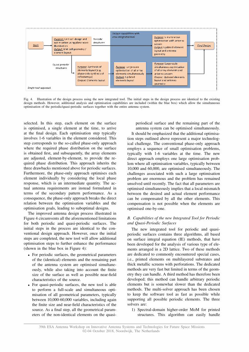
Fig. 4. Illustration of the design process using the new integrated tool. The initial steps in the design process are identical to the existingdesign methods. However, additional analysis and optimisation capabilities are included (within the blue box) which allow the simultaneousoptimisation of the periodic/quasi-periodic surfaces together with the entire antenna system.
selected. In this step, each element on the surfaceis optimised, a single element at the time, to arriveat the final design. Each optimisation step typicallyinvolves 1-6 variables in the element considered. Thisstep corresponds to the so-called phase-only approachwhere the required phase distribution on the surfaceis obtained first, and subsequently, the array elementsare adjusted, element-by-element, to provide the re-quired phase distribution. This approach inherits thethree drawbacks mentioned above for periodic surfaces.Furthermore, the phase-only approach optimises eachelement individually by considering the local phaseresponse, which is an intermediate quantity. The ac-tual antenna requirements are instead formulated interms of the secondary pattern performance. As aconsequence, the phase-only approach breaks the directrelation between the optimisation variables and theoptimisation goals, leading to suboptimal designs.
The improved antenna design process illustrated inFigure 4 circumvents all the aforementioned limitationsfor both periodic and quasi-periodic surfaces. Theinitial steps in the process are identical to the con-ventional design approach. However, once the initialsteps are completed, the new tool will allow additionaloptimisation steps to further enhance the performance(shown in the blue box in Figure 4):
• For periodic surfaces, the geometrical parametersof the (identical) elements and the remaining partof the antenna system are optimised simultane-ously, while also taking into account the finitesize of the surface as well as possible near-fieldcharacteristics of the source.
• For quasi-periodic surfaces, the new tool is ableto perform a full-scale and simultaneous opti-misation of all geometrical parameters, typicallybetween 10,000-60,000 variables, including againthe finite size and near-field characteristics of thesource. As a final step, all the geometrical param-eters of the non-identical elements on the quasi-
periodical surface and the remaining part of theantenna system can be optimised simultaneously.
It should be emphasized that the additional optimisa-tion steps outlined above represent a major technolog-ical challenge. The conventional phase-only approachemploys a sequence of small optimisation problems,typically with 1-6 variables at the time. The newdirect approach employs one large optimisation prob-lem where all optimisation variables, typically between10,000 and 60,000, are optimised simultaneously. Thechallenges associated with such a large optimisationproblem are enormous and the problem has remainedunsolved until recently. The fact that all parameters areoptimised simultaneously implies that a local mismatchbetween the desired and actual element performancecan be compensated by all the other elements. Thiscompensation is not possible when the elements areoptimised one-by-one.
B. Capabilities of the new Integrated Tool for Periodicand Quasi-Periodic Surfaces
The new integrated tool for periodic and quasi-periodic surfaces contains three algorithms, all basedon surface integral equation (IE) methods, that havebeen developed for the analysis of various type of ele-ments arranged in a 2D lattice. Two of these methodsare dedicated to commonly encountered special cases,i.e., printed elements on multilayered substrates andthick metallic screens with perforations. The dedicatedmethods are very fast but limited in terms of the geom-etry they can handle. A third method has therefore beendeveloped; this method can handle arbitrary periodicelements but is somewhat slower than the dedicatedmethods. The multi-solver approach has been chosento keep the software tool as fast as possible whilesupporting all possible periodic elements. The threesolvers are:
1) Spectral-domain higher-order MoM for printedstructures. This algorithm can easily handle
39th ESA Antenna Workshop on Innovative Antenna Systems and Technologies for Future Space Missions02-04 October 2018, Noordwijk, The Netherlands

many dielectric layers, it is efficient and well-validated, however, the metallization layers mustbe confined to the interfaces between the dielec-tric layers.
2) Periodic MoM for thick perforated metallicscreens which are often used in dichroic platefilters. For such structures, a fast IE solutionhybridized with mode-matching has been devel-oped which results in an algorithm simillar tothat of [10].
3) Higher-order Periodic MoM for arbitrary 3Dobjects arranged in a 2D lattice. This algorithmcan handle any unit cell geometry and can be ap-plied where the two algorithms discussed abovecannot. The formulation is derived from the workin [11] which we have extended to handle higher-order basis functions, composite metallic/dielec-tric structures, as well as both finite and infinitedielectric regions.
In addition to the periodic solvers outlined above,the new tool also includes two accurate methods forcomputing the radiation patterns of finite-sized periodicor quasi-periodic surfaces. In the first method, eacharray element is analyzed assuming local periodicity,i.e., the individual element is assumed to be located inan infinite array of identical elements [12]. The reflec-tion/transmission characteristics of the each elementare determined by any of the three solvers listed aboveand are subsequently used to form equivalent currentsfrom which the far-field is calculated. The equivalentmagnetic and electric currents are constructed on asurface that encloses the finite sized surface. An alter-native method has been derived by considering the sur-face as a continuous modulated surface impedance. Bydoing so, we remove any references to the individualarray elements. By applying the equivalence principle,equivalent currents enclosing the finite sized surface isagain defined. Both methods have also been extendedto handle curved surfaces accurately.
The analysis methods described above have beenimplemented in the flexible GRASP framework thatallows any number of periodic or quasi-periodic sur-faces to be defined, as well as being combined withother methods available in GRASP or the feed chaindesign tool described in the previous chapter. Powerfuloptimisation capabilities are also included, as well as alibrary of commonly encountered unit cell geometriesor even arbitrarily shaped user-defined elements.
IV. APPLICATION EXAMPLES
The capabilities of the new software tools arenow illustrated with two design examples involv-ing multibeam antennas. In both cases, we considera single-feed-per-beam (SFPB) multi-beam reflectorsetup which are commonly used on High ThroughputSatellites (HTS). In the most classical implementation,four reflector apertures are needed to provide a large
number of highly directive beams using frequency andpolarisation discrimination between adjacent beams.This configuration is also referred to as a 4-colourfrequency/polarization reuse scheme. In the first exam-ple, we optimise the feed cluster directly to minimisethe interference between beams while in the secondexample, we show that a reflectarray with polarisation-selective beam steering can be used to reduce thenumber of required reflectors from four to two.
A. Design of single-feed-per-beam multibeam antenna
In this example, we consider the design of a reflectorand a feed cluster intended for a classical 4-colourSFPB setup using four apertures in total. The selectedconfiguration is shown in Figure 5 where a feedcluster of 19 feeds are illuminating a 1.2 m reflectorcorresponding to 80λ at 20 GHz. The feed cluster usesthree different kinds of feeds, one feed at the centre, 6feeds in the ring around the centre feed, and 12 feed inthe outer ring. The geometrical parameters of the feedhorns are optimised and optimisation goals are definedon the secondary patterns of the 19 beams and on thereturn loss of the feed chain. The software allows foroptimising the patterns of the individual beams, as wellas the C/I quantity, i.e., the interference of a beam fromall other beams.
A detailed view of the feed cluster is shown in Figure6. In addition to the 3 different horn geometries, thefeeds include a fairly complex feed network. This feednetwork is identical for all feeds meaning that it needsonly to be analysed once. Each feed network consists ofthe following components from the built-in WaveguideLibrary:
• 10 straight pieces of rectangular waveguide• 4 180◦ smooth bends of rectangular waveguide• 4 90◦ smooth bends of rectangular waveguide• 2 Stepped rectangular waveguides• 2 Junctions between 3 rectangular waveguides• 2 Linearly tapered rectangular waveguides• 1 custom 5-port waveguide turnstile defined using
a CAD fileThe fact that some of the components are identical,further reduces the computation time since they needonly be analysed once. The 3 different horn geometrieseach consist of a sequence of 5 linear profiles incombination with an exterior aperture, again beingdefined using the built-in Waveguide Library.
The initial design assumes that all 19 feed hornsshare the same geometrical design. This design isoptimised with goals on the secondary pattern of the19 individual beams. For each beam goals are set tothe beam’s Centre Directivity, the Edge-of-CoverageDirectivity, and the C/I. From the resulting design thefeed geometries are optimised a second time. This timethe 3 different feeds are allowed to diverge resulting ina total of 28 optimisation variables. The same goals areapplied again, however, due to the different positions
39th ESA Antenna Workshop on Innovative Antenna Systems and Technologies for Future Space Missions02-04 October 2018, Noordwijk, The Netherlands
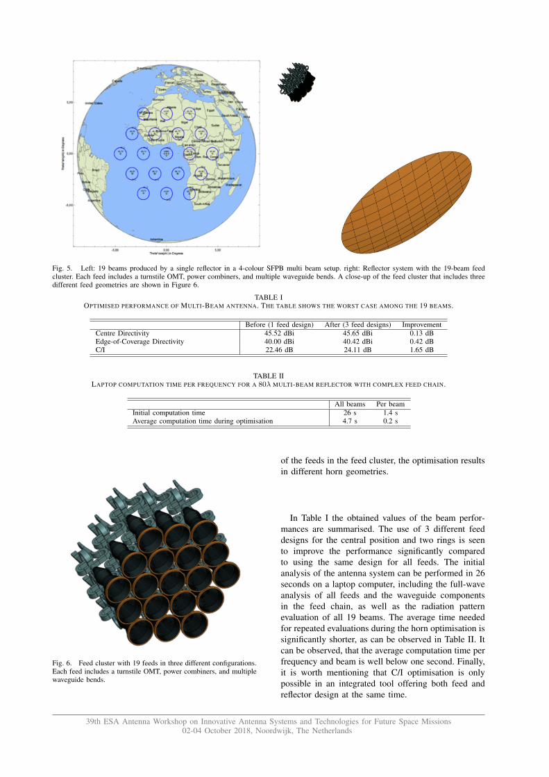
Fig. 5. Left: 19 beams produced by a single reflector in a 4-colour SFPB multi beam setup. right: Reflector system with the 19-beam feedcluster. Each feed includes a turnstile OMT, power combiners, and multiple waveguide bends. A close-up of the feed cluster that includes threedifferent feed geometries are shown in Figure 6.
TABLE IOPTIMISED PERFORMANCE OF MULTI-BEAM ANTENNA. THE TABLE SHOWS THE WORST CASE AMONG THE 19 BEAMS.
Before (1 feed design) After (3 feed designs) ImprovementCentre Directivity 45.52 dBi 45.65 dBi 0.13 dBEdge-of-Coverage Directivity 40.00 dBi 40.42 dBi 0.42 dBC/I 22.46 dB 24.11 dB 1.65 dB
TABLE IILAPTOP COMPUTATION TIME PER FREQUENCY FOR A 80λ MULTI-BEAM REFLECTOR WITH COMPLEX FEED CHAIN.
All beams Per beamInitial computation time 26 s 1.4 sAverage computation time during optimisation 4.7 s 0.2 s
Fig. 6. Feed cluster with 19 feeds in three different configurations.Each feed includes a turnstile OMT, power combiners, and multiplewaveguide bends.
of the feeds in the feed cluster, the optimisation resultsin different horn geometries.
In Table I the obtained values of the beam perfor-mances are summarised. The use of 3 different feeddesigns for the central position and two rings is seento improve the performance significantly comparedto using the same design for all feeds. The initialanalysis of the antenna system can be performed in 26seconds on a laptop computer, including the full-waveanalysis of all feeds and the waveguide componentsin the feed chain, as well as the radiation patternevaluation of all 19 beams. The average time neededfor repeated evaluations during the horn optimisation issignificantly shorter, as can be observed in Table II. Itcan be observed, that the average computation time perfrequency and beam is well below one second. Finally,it is worth mentioning that C/I optimisation is onlypossible in an integrated tool offering both feed andreflector design at the same time.
39th ESA Antenna Workshop on Innovative Antenna Systems and Technologies for Future Space Missions02-04 October 2018, Noordwijk, The Netherlands
B. Design of a Multi-beam Ka-band Reflectarray forHTS Applications
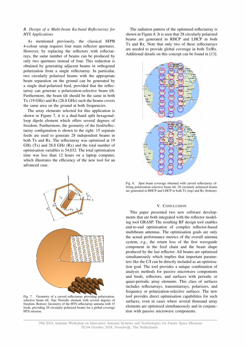
As mentioned previously, the classical SFPB4-colour setup requires four main reflector apertures.However, by replacing the reflectors with reflectar-rays, the same number of beams can be produced byonly two apertures instead of four. This reduction isobtained by generating adjacent beams in orthogonalpolarization from a single reflectarray. In particular,two circularly polarized beams with the appropriatebeam separation on the ground can be generated bya single dual-polarized feed, provided that the reflec-tarray can generate a polarization-selective beam tilt.Furthermore, the beam tilt should be the same in bothTx (19 GHz) and Rx (28.8 GHz) such the beams coversthe same area on the ground at both frequencies.
The array elements selected for this application isshown in Figure 7, it is a dual-band split hexagonal-loop dipole element which offers several degrees offreedom. Furthermore, the geometry of the feed/reflec-tarray configuration is shown to the right: 15 separatefeeds are used to generate 28 independent beams inboth Tx and Rx. The reflectarray was optimised at 19GHz (Tx) and 28.8 GHz (Rx) and the total number ofoptimisation variables is 54,032. The total optimisationtime was less than 12 hours on a laptop computer,which illustrates the efficiency of the new tool for anadvanced case.
Fig. 7. Geometry of a curved reflectarray providing polarization-selective beam tilt. Top: Periodic element with several degrees offreedom. Bottom: Geometry of the HTS reflectarray antenna with 15feeds, providing 29 circularly polarized beams for a global coverageHTS mission.
The radiation pattern of the optimised reflectarray isshown in Figure 8. It is seen that 28 circularly polarizedbeams are generated in RHCP and LHCP in bothTx and Rx. Note that only two of these reflectarraysare needed to provide global coverage in both Tx/Rx.Additional details on this concept can be found in [13].
Fig. 8. Spot beam coverage obtained with curved reflectarray of-fering polarization-selective beam tilt. 28 circularly polarized beamsare generated in RHCP and LHCP in both Tx (top) and Rx (bottom).
V. CONCLUSION
This paper presented two new software develop-ments that are both integrated with the reflector model-ing tool GRASP. The resulting RF design tool enablesend-to-end optimisation of complex reflector-basedmultibeam antennas. The optimisation goals are onlythe actual performance metrics of the overall antennasystem, e.g., the return loss of the first waveguidecomponent in the feed chain and the beam shapeproduced by the last reflector. All beams are optimisedsimultaneously which implies that important parame-ters like the C/I can be directly included as an optimisa-tion goal. The tool provides a unique combination ofanalysis methods for passive microwave componentsand feeds, reflectors, and surfaces with periodic orquasi-periodic array elements. This class of surfacesincludes reflectarrays, transmitarrays, polarizers, andfrequency or polarization-selective surfaces. The newtool provides direct optimisation capabilities for suchsurfaces, even in cases where several thousand arrayelements are optimised simultaneously and in conjunc-tion with passive microwave components.
39th ESA Antenna Workshop on Innovative Antenna Systems and Technologies for Future Space Missions02-04 October 2018, Noordwijk, The Netherlands

VI. REFERENCES
[1] E. Jørgensen, N. Vesterdal, and P. Meincke, Software Tool forCombined Optimisation of Reflector and Feed Systems. finalreport, ESA contract 4000116471/16/NL/US, TICRA, 2018.
[2] M. Zhou and E. Jørgensen, Design Tool for High PerformanceAntenna Systems with Periodic and Quasi-Periodic Surfaces.final report, ESA contract 4000116990/16/NL/US, TICRA,2018.
[3] E. Kuhn and V. Hombach, “Computer-aided analysis of cor-rugated horns with axial or ring-loaded radial slots,” in 3rdInternat. Conf. on Antennas and Propagation (ICAP 83), 1983,pp. 127–131.
[4] TICRA, CHAMP User’s Manual, 2016.
[5] H.-H. Viskum, et al., Final Phase I Report on INTEL-1370,S-681-03. Læderstræde 34, DK-1201 Copenhagen K: TICRA,1994.
[6] W. Wessel, T. Sieverding, and F. Arndt, “Mode-MatchingAnalysis of General Waveguide Multiport Junctions,” MTT-SInt. Microwave Symp. Digest, no. 4, pp. 1273–1276, 1999.
[7] L. S. Drioli, “Metodo Numerico Full Wave per lo Studioe la Progettazione di Feed System per Antenne ad ElevataEfficienza,” ph.d. thesis, Universita degli Studi di Firenze,Firenze, Italy, 2001.
[8] E. Jørgensen, J. Volakis, P. Meincke, and O. Breinbjerg,“Higher Order Hierarchical Legendre Basis Functions for Elec-tromagnetic Modeling,” IEEE Transactions on Antennas andPropagation, vol. 52, no. 11, pp. 2985–2995, Nov. 2004.
[9] C. J. Reddy, M. D. Deshpande, C. R. Cockrell, and F. B. Beck,“Finite Element Method for Eigenvalue Problems,” NASA Tech-nical Paper, no. 3485, December 1994.
[10] M. Bozzi and L. Perregrini, “Analysis of multilayered printedfrequency selective surfaces by the MoM/BI-RME method,”IEEE Trans. Antennas Propag., vol. 51, no. 10, pp. 2830–2836,2003.
[11] I. Stevanovic, P. Crespo-Valero, K. Blagovic, F. Bongard, andJ. R. Mosig, “Integral-equation analysis of 3-D metallic objectsarranged in 2-D lattices using the Ewald transformation,” IEEETrans. Antennas Propag., vol. 54, no. 10, pp. 3688–3697, 2006.
[12] D. M. Pozar, S. D. Targonski, and H. D. Syrigos, “Design ofmillimeter wave microstrip reflectarrays,” IEEE Trans. Anten-nas Propag., vol. 45, no. 2, pp. 287–296, 1997.
[13] M. Zhou, S. B. Sørensen, Y. Brand, S. Maltais, J. Bellemore,and G. Toso, “Curved reflectarrays for future multiple beamantenna applications in ka-band,” in this conference, ESTEC,Noordwijk, The Netherlands, 2018.
39th ESA Antenna Workshop on Innovative Antenna Systems and Technologies for Future Space Missions02-04 October 2018, Noordwijk, The Netherlands