Embed Size (px)
Citation preview

These instructions must be read fully before commencing installation.
REVOLUTION SLC Installation & Maintenance

Tel 01384 275800 Fax 01384 275810 Email [email protected] Website eltafans.com2
Installation InstructionsREVOLUTION SLC
1.0 General1.1 It is important these Installation and Maintenance Instructions are fully adhered to.1.2 Full details of the unit supplied are shown on the product nameplate. If in doubt about any detail contact Elta Fans Ltd or its agents for clarification.1.3 All electrical installation must be carried out by suitably qualified and competent personnel in accordance with all current statutory requirements.1.4 These instructions cover only the Elta Fans Ltd product and do not include the supply or installation of any safety equipment that may be required e.g. adequate guarding or protection from rotating parts and proper electrical isolation.1.5 Any declarations made by Elta Fans Ltd about product installation and safety, are dependant on the fan equipment being used within installations which themselves meet the requirements of the relevant Standards and Directives of your region.1.6 The fan is designed for use in an ambient temperature of -20°C up to +54°C and up to 95% relative humidity. EC fans are designed for ambient temperatures up to +60°C. The fan is not suitable for corrosive or explosive atmospheres.1.7 The installer should provide easy access to the fan to facilitate future maintenance.1.8 The installer should ensure the fan is adequately supported.1.9 This product is not intended for use by persons (including children) with reduced physical, sensory or mental capabilities, or lack of experience and knowledge, unless they have been given supervision or instruction concerning use of the product by a person responsible for their safety. Children should be supervised to ensure that they do not play with the product.
2.0 Installation
WARNING – The fan must be isolated from the power supply during installation and maintenance. The fan must be earthed in accordance with the local regulations.
2.1 Upon receipt, the fan equipment should be visually inspected to check for any damage. Ensure that the impeller is free to rotate.2.2 If there are any queries concerning the fan equipment, Elta Fans Ltd should be contacted prior to the installation.2.3 The fan must be securely mounted in the desired position to suit the application. The fan can be mounted at any angle.2.4 Check the details on the motor rating plate to ensure that the correct power supply (voltage, frequency and phase) is available. An incorrect power supply will lead to permanent damage to the fan motor.2.5 Refer to the appropriate wiring diagram. Ensure that all earth connections are made.2.6 Means for electrical disconnection must be incorporated in the wiring installation in accordance with the relevant wiring and electrical regulations.2.7 Precaution must be taken to locate the exhaust discharge terminal so as to avoid the backflow of gases into the room from the open flue of gas or other fuel burning appliances.
3.0 Start Up
WARNING – It is not good for any fan motor, for the user to use the power supply isolator to a fan as a means of day to day control. This can reduce the life expectancy of the fan motor and may even lead to motor failure unlikely to be covered under our warranty. The power supply isolator should only be used as a means of isolation of the power supply for maintenance and servicing requirements. Day to day control should be provided to the user by means of one of the various type of control options as per the wiring diagrams which follow in this document.
To help protect our fan motors, there is a delayed start function when the mains power is switched off at the isolator. A period of at least 5 minutes should be allowed between power disconnection and reconnection. If the user is determined to switch the fan on and off at the power supply isolator then the installer must advise the user of this motor protection function so that they wait the necessary period of up to 5 minutes between switching on and off.
WARNING – When switching off mains power for maintenance / servicing, High voltages are present at the terminals and within the motor for up to 10 minutes after disconnection of the electrical supply.
3.1 Before power is supplied to the unit, check that the wiring is correct as per the fan connection diagram.3.2 At initial start-up, check that impeller rotation and airflow direction is correct.3.3 Check that the motor amperage draw does not exceed the nameplate rating. EC fans only:3.4 Minimum interval between consecutive starts: 5 minutes.3.5 Maximum 1 connection from power supply cycle per 5 minutes.
AC

Elta Fans Limited has a policy of continuous product development and improvement and therefore reserves the right to supply products which may differ from those illustrated and described in this publication. Confirmation of dimensions and data will be supplied on request. 3
Installation InstructionsREVOLUTION SLC AC
4.0 Fan Maintenance4.1 Inspection of the fan at least once every 12 months is recommended to ensure that the motor, fan blades, and supporting guards, are clean. Any build up of dust and deposits on the blades or guards should be removed using a non-abrasive cleaner.4.2 All fastenings should be checked for tightness. In addition, all rotating items should be checked.4.3 Bearings are of the ‘sealed for life’ type and will not need a detailed inspection.
WARNING – Fuses/circuit breakers are used to provide short circuit protection only. A starter panel with overload protection should be used to protect the motor.
EC Fans Only: These fans are fitted with an auto-reset thermal contact which switches the fan off in the event of a fault condition. Once the motor cools down the fan may start unexpectedly.
Only a suitably qualified and competent person may carry out maintenance after the electrical supply has been isolated.
5.0 Guarantee Elta Fans Ltd will, free of charge, within a period of 1 year from the date of dispatch from their works, repair or at its option replace any goods which are proved to have defects as a result of defective materials or workmanship. The goods MUST be returned to Elta Fans Ltd carriage paid for examination.

Tel 01384 275800 Fax 01384 275810 Email [email protected] Website eltafans.com4
Installation InstructionsREVOLUTION SLC AC
A3A3SLC-ACC-GA
1:20
SLC GA
BELL MOUTH INLETACCESSORY AVAILABLE
FROM ELTA
FLEXIBLE CONNECTIONACCESSORY AVAILABLE
FROM ELTAMATCHING FLANGE
ACCESSORY AVAILABLEFROM ELTA
IMPELLER SIDE GUARDACCESSORY AVAILABLE
FROM ELTA
DAMPERACCESSORY AVAILABLE
FROM ELTA
MOUNTING FEETACCESSORY AVAILABLE
FROM ELTA
FAN UNIT
NOTE:FIXINGS SUPPLIED
BY CUSTOMER
REFER TO CATALOGUE/OFFICEFOR ACCESSORY DETAILS
SILENCERACCESSORY AVAILABLE
FROM ELTA
FAN WITHMATCHING FLANGES
FAN WITHFLANGES AND FLEXIBLE
CONNECTIONS
FAN WITHMOUNTING FEET
FAN WITHMOUNTING FEET AND AV
MOUNTS
FAN WITHBELL MOUTH INLET
FAN WITHDAMPER
FAN WITHIMPELLER SIDE GUARDS
AV MOUNTACCESSORY AVAILABLE
FROM ELTATYPE DEPENDANT
ON FAN SIZE
FAN WITHSILENCERS
1
2
3
4
5
7
6
3rd ANGLE PROJECTION DO NOT SCALE-IF IN DOUBT, ASK!
DRAWING No.
SHEET OF ISSUE
DRAWN BY
DATE
SCALE STATUS
APPROVED
CHECKED
FINISH
MATERIAL
SPECIFICATION
DIMENSIONS ARE IN mm UNLESS STATED OTHERWISE
THIS IS A C.A.D. PRODUCED DRAWING
AND THEREFORE NO SUBSEQUENTMANUAL MODIFICATIONS WILL BE
ALLOWED.
TITLE
UNLESS OTHERWISE STATED.
BYISS CN.
DATE CHKD
ISS CN. BY
DATE
CHKD
ISS CN. BY
DATE CHKD
ISS CN. BY
DATE CHKD
A
1
B C D E F G
2
3
4
5
7
6
7
6
5
4
3
2
1
A CB E F G
DATE
ISS CN.
CHKD DATE
BY ISS CN.
CHKD
BY
DATE
ISS CN.
CHKD DATE
BYCN. ISS
CHKD
BY
N/A
N/A
1 1 A
AWM
03-03-15
DMO
-
I
USED ON
OF THESE VIEWS FOR MANUFACTURINGPURPOSES ARE AT SUPPLIERS RISK.
REFERENCE PURPOSES ONLY. USE
ANY DEVELOPMENT VIEWS SHOWN ONTHIS DRAWING ARE SHOWN FOR
ORIENTATION OF FAN MUST BE AS PER
DRAWING OR REFER TO ELTA
GENERAL ± 1.0TOLERANCES
N/A
D
in writing from its owners Elta Fans Ltd.
purpose other than that for which it is supplied
speci�cation document which is supplied incon�dence and which must not be used for any
and must not be reproduced without permission
Elta Fans Ltd. own the copyright of this drawing/
Tel. 01489 566500 Fax. 01489 566555FAREHAM, HAMPSHIRE. PO15 5ST.SEGENSWORTH INDUSTRIAL ESTATE,17 BARNES WALLIS ROAD,ELTA FANS LTD,
C

Elta Fans Limited has a policy of continuous product development and improvement and therefore reserves the right to supply products which may differ from those illustrated and described in this publication. Confirmation of dimensions and data will be supplied on request. 5
REVOLUTION SLCInstallation Instructions
GND 10V E1
MIN MAX
E1GND
ST1
ST2
ST2
E110VGND
MAXMIN
ST1
GND E1
THE ABOVE DIAGRAM SHOWS "ST2".
"ST2" CONNECTIONS ARE FACTORY FITTED.
GND = COMMON•10V = 10VDC INPUT•E1 = 0-10VDC OUTPUT•
YOU CAN DETERMINE THE CURRENT VDC OUTPUT BYDISCONNECTING POWER TO THE UNIT, SETTING AMULTIMETER TO OHMS (Ω) AND PLACING THE TEST PROBESBETWEEN GND AND E1
PLEASE USE THE ESTIMATED ADJUSTMENT GUIDE FOR REFERENCE
THIS IS THE INTERNAL POTENTIOMETERTHIS POTENTIOMETER CAN BE ADJUSTED FOR SINGLE SPEED SETTING OR MAX SPEED SELECTION
THIS LINK/JUMPER SHOULD BE REMOVEDWHEN USING AN EXTERNAL POTENTIOMETEROR EXTERNAL CONTROL SIGNAL CONNECTEDTO "ST1"
THE ABOVE DIAGRAM SHOWS "ST1".
"ST1" CONNECTIONS ARE CLASSED AS"CUSTOMER/USER CONNECTIONS".
GND = COMMON•+ = VDC OUTPUT AS SET BY•
INTERNAL POTENTIOMETERE1 = 0-10VDC INPUT•
149-CD-POT
10/07/2018MK-149-CD-POT Issue: Saved Date:A
All wiring and control equipment must comply to the latest IEE regulations, in particular part 552-01-02/03. 149-CD-POT Issue A: 10.07.2018Check the individual product accessories table for fan controller compatibility.
149-CD-POTThe 149-CD-POT is a commissiong device designed to be used with our EC range of fans. The device will allow the for the installer to set the maximum operating speed of the fan that it is connected to. The installer or commissioning engineer can adjust the fan speed using the potentiometer built onto the 149-CD-POT board. This potentionmeter can either be used for single speed adjustment or to set a maximum speed for the fan to operate at when an external control source is used. If external speed control is required, the jumper connection next to the potentionmeter on the board would need to be removed, the installer can then connect to ST1 (using the diagram provided). When an external speed control is fitted, the maximum speed setting available to the external control is limited by the potentiometer setting of the commissioning device.
EC
Please note: This is an estimated adjustment guide
149-CD-POT
The 149-CD-POT is a commissiong device designed to be used with our EC range of fans.
This device will be as standard with our box fan range from May 2018.
The device will allow the for the installer to set the maximum operating speed of the fan that it isconnected to.
The installer or commissioning engineer can adjust the fan speed using the potentiometer built onto the149-CD-POT board. This potentionmeter can either be used for single speed adjustment or to set amaximum speed for the fan to operate at when an external control source is used.
If external speed control is required, the jumper connection next to the potentionmeter on the boardwould need to be removed, the installer can then connect to ST1 (using the diagram provided).
When an external speed control is �tted, the maximum speed setting available to the external control islimited by the potentiometer setting of the commissioning device.
10/07/2018MK-149-CD-POT Issue: Saved Date:A
Level / Speed OHMS (Ω)
10 10 (Ω)
9 9 (Ω)
8 8 (Ω)
7 7 (Ω)
6 6 (Ω)
5 5 (Ω)
4 4 (Ω)
3 3 (Ω)
2 1.5 (Ω)
1 500 (Ω)
0 1 (Ω)149-CD-POT

Tel 01384 275800 Fax 01384 275810 Email [email protected] Website eltafans.com6
Single Phase 220V - 240V / 50Hz Three Phase 380V - 415V / 50Hz
PageNo.
Product Code
Wiring Diagram No.
7 SLC400/4-1AC 152-502
7 SLC450/2-1AC 152-502
7 SLC450/4-1AC 152-502
7 SLC500/4A-1AC 152-502
7 SLC500/4B-1AC 152-502
7 SLC560/4A-1AC 152-502
7 SLC560/4B-1AC 152-502
7 SLC630/4-1AC 152-502
7 SLC630/4B-1AC 152-502
PageNo.
Product Code
Wiring Diagram No.
8 SLC315/4-3AC 152-600
8 SLC355/2A-3AC 152-600
8 SLC450/2A-3AC 152-600
8 SLC450/4-3AC 152-600
9 SLC500/2A-3AC 152-601
9 SLC500/2B-3AC 152-601
8 SLC500/4A-3AC 152-600
8 SLC500/4B-3AC 152-600
9 SLC560/2-3AC 152-601
8 SLC560/4A-3AC 152-600
8 SLC560/4B-3AC 152-600
8 SLC560/4C-3AC 152-600
8 SLC630/4A-3AC 152-600
8 SLC630/4B-3AC 152-600
8 SLC710/4A-3AC 152-600
9 SLC710/4B-3AC 152-601
8 SLC710/6A-3AC 152-600
8 SLC710/6B-3AC 152-600
9 SLC800/4A-3AC 152-601
9 SLC800/4B-3AC 152-601
8 SLC800/6A-3AC 152-600
9 SLC800/6B-3AC 152-601
9 SLC900/4A-3AC 152-601
9 SLC900/4B-3AC 152-601
9 SLC900/6A-3AC 152-601
9 SLC900/6B-3AC 152-601
8 SLC900/8-3AC 152-600
9 SLC1000/4A-3AC 152-601
9 SLC1000/4B-3AC 152-601
9 SLC1000/4C-3AC 152-601
9 SLC1000/6A-3AC 152-601
9 SLC1000/6B-3AC 152-601
8 SLC1000/8-3AC 152-600
Wiring DiagramsREVOLUTION SLC
Please use the table(s) below to match up the product code and the wiring diagram number.
AC

Elta Fans Limited has a policy of continuous product development and improvement and therefore reserves the right to supply products which may differ from those illustrated and described in this publication. Confirmation of dimensions and data will be supplied on request. 7
Single Phase 220V - 277V / 50Hz or 60Hz
PageNo.
Product Code
Wiring Diagram No.
10 SLC315-1EC 152-710
10 SLC355-1EC 152-710
10 SLC400-1EC 152-710
10 SLC450-1EC 152-710
10 SLC500-1EC 152-710
10 SLC560-1EC 152-710
10 SLC630-1EC 152-710
Wiring DiagramsREVOLUTION SLC
Please use the table(s) below to match up the product code and the wiring diagram number.
EC

Tel 01384 275800 Fax 01384 275810 Email [email protected] Website eltafans.com8
Wiring Diagrams152-502 AC
16/08/2018MK-152-502 Issue: Saved Date:D
ALL WIRING AND CONTROL EQUIPMENT MUST COMPLY TO THELATEST IEE REGULATIONS, IN PARTICULAR PART 552-01-02/03
VARIABLE SPEED CONNECTION CONTROLLER TYPE TC12, TC14,TC18, TC110, TC112
BROW
N
BROW
N
BLUE
GREE
N/YE
LLOW
EL N
CONTROLLERTERMINAL BOX
GREE
N/YE
LLOW
BROW
N
BLUE
REMOVE LINKBETWEEN U1 - Z2 Z2U1 Z1
U2CAP1 CAP2
220 - 240V 1PH 50Hz SUPPLY
AUXNL NLE
ENL
Z2U1 Z1
U2CAP1 CAP2
220 - 240V 1PH 50Hz SUPPLY
FIXED SPEED CONNECTION
GREE
N/YE
LLOW
BLUE
BROW
N
All wiring and control equipment must comply to the latest IEE regulations, in particular part 552-01-02/03. MK-152-502 Issue D: 16.08.2018Check the individual product accessories table for fan controller compatibility.
Elta Fans Limited has a policy of continuous product development and improvement and therefore reserves the right to supply products which may differ from those illustrated and described in this publication. Confirmation of dimensions and data will be supplied on request. 9
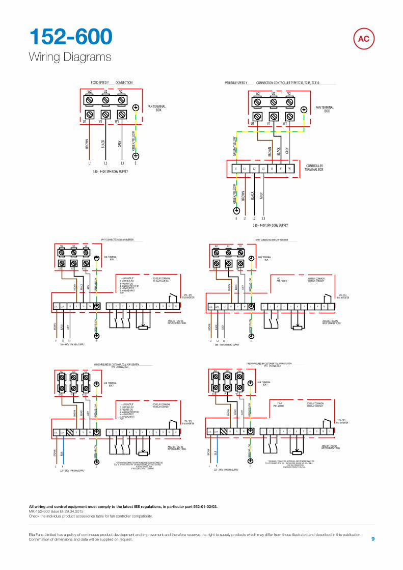
Wiring Diagrams152-600 AC
Y RECONFIGURED BY CUSTOMER TO Δ FOR USE WITH 1PH - 3PH INVERTER
4 5 6 731 2 8 11109L1/L U V WL3L2/N
BROW
N
BLAC
K
GREY
GREE
N/YE
LLOW
BROW
N
BLUE
GREE
N/YE
LLOW
1 TO 7PRE - WIRED
EL
FAN TERMINALBOX *
220 - 240V 1PH 50Hz SUPPLYN
10 RELAY COMMON11 RELAY CONTACT
1PH - 3PHIP55 INVERTER
ANALOG / DIGITALINPUT CONNECTIONS
V1 W1U1
V2U2W2
* STANDARD Y CONNECTED MOTOR WILL NEED TO BE RECONNECTEDTO Δ TO OPERATE WITH 1PH - 3PH INVERTER, ENSURE FAN IS SUITABLE
FOR THIS CONNECTION.IF IN DOUBT CONTACT ELTA FANS
4 5 6 731 2 8 11109L1/L U V WL3L2/N
W2 U2 V2
U1 W1V1
L3
3PH Y CONNECTED FAN C/W INVERTER
ANALOG / DIGITALINPUT CONNECTIONS
3PH - 3PHIP20 INVERTER
10 RELAY COMMON11 RELAY CONTACT
L2380 - 440V 3PH 50Hz SUPPLY
FAN TERMINALBOX
L1 E
1: +24V OUTPUT2: STOP/RUN DI13: FWD/REV DI24: ANALOG/PRESET DI35: +10V OUTPUT6: ANALOG INPUT7: 0V
GREE
N/YE
LLOW
GREY
BLAC
K
BROW
N
GREE
N/YE
LLOW
GREY
BLAC
K
BROW
N
L2 EL3L1
380 - 440V 3PH 50Hz SUPPLY
FIXED SPEED Y CONNECTION
W2 U2 V2
U1 W1V1
FAN TERMINALBOX
GREE
N/YE
LLOW
GREY
BLAC
K
BROW
N
4 5 6 731 2 8 11109L1/L U V WL3L2/N
BROW
N
BLAC
K
GREY
GREE
N/YE
LLOW
BROW
N
BLAC
K
GREY
GREE
N/YE
LLOW
1 TO 7PRE - WIRED
EL1
FAN TERMINALBOX
380 - 440V 3PH 50Hz SUPPLYL2
10 RELAY COMMON11 RELAY CONTACT
3PH - 3PHIP55 INVERTER
ANALOG / DIGITALINPUT CONNECTIONS
3PH Y CONNECTED FAN C/W INVERTER
L3
V1 W1U1
V2U2W2
380 - 440V 3PH 50Hz SUPPLY
VARIABLE SPEED Y CONNECTION CONTROLLER TYPE TC33, TC35, TC310
L1 L2 L3E
CONTROLLERTERMINAL BOX
V1 W1U1
V2U2W2
FAN TERMINALBOX
GREE
N/YE
LLOW
GREY
BLAC
K
BROW
N
GREE
N/YE
LLOW
GREY
BLAC
K
BROW
N
WE L3 U VL2L1
L1/L U V WL3L2/N 4 5 6 731 2 8 11109
BROW
N
BLAC
K
GREY
GREE
N/YE
LLOW
BROW
N
BLUE
GREE
N/YE
LLOW
1: +24V OUTPUT2: STOP/RUN DI13: FWD/REV DI24: ANALOG/PRESET DI35: +10V OUTPUT6: ANALOG INPUT7: 0V
EL
FAN TERMINALBOX *
220 - 240V 1PH 50Hz SUPPLYN
10 RELAY COMMON11 RELAY CONTACT
1PH - 3PHIP20 INVERTER
ANALOG / DIGITALINPUT CONNECTIONS
V1 W1U1
V2U2W2
* STANDARD Y CONNECTED MOTOR WILL NEED TO BE RECONNECTEDTO Δ TO OPERATE WITH 1PH - 3PH INVERTER, ENSURE FAN IS SUITABLE
FOR THIS CONNECTION.IF IN DOUBT CONTACT ELTA FANS
Y RECONFIGURED BY CUSTOMER TO Δ FOR USE WITH 1PH - 3PH INVERTER
ALL WIRING AND CONTROL EQUIPMENT MUST COMPLY TO THELATEST IEE REGULATIONS, IN PARTICULAR PART 552-01-02/03
29/04/2015MK-152-600 Issue: Saved Date: BAll wiring and control equipment must comply to the latest IEE regulations, in particular part 552-01-02/03. MK-152-600 Issue B: 29.04.2015Check the individual product accessories table for fan controller compatibility.

Tel 01384 275800 Fax 01384 275810 Email [email protected] Website eltafans.com10
Wiring Diagrams152-601 AC
L1/L U V WL3L2/N 4 5 6 731 2 8 11109
L3
3PH Δ CONNECTED FAN C/W INVERTER
ANALOG / DIGITALINPUT CONNECTIONS
3PH - 3PHIP20 INVERTER
10 RELAY COMMON11 RELAY CONTACT
L2
380 - 440V 3PH 50Hz SUPPLY
FAN TERMINALBOX
L1 E
1: +24V OUTPUT2: STOP/RUN DI13: FWD/REV DI24: ANALOG/PRESET DI35: +10V OUTPUT6: ANALOG INPUT7: 0V
GREE
N/YE
LLOW
GREY
BLAC
K
BROW
N
W2 U2 V2
U1 W1V1
GREE
N/YE
LLOWGR
EY
BLAC
K
BROW
NBR
OWN
BLAC
K
GREY
GREE
N/YE
LLOW
FAN TERMINALBOX
L2 EL3L1
380 - 440V 3PH 50Hz SUPPLY
FIXED SPEED Δ CONNECTION
W2 U2 V2
U1 W1V1
1 TO 7PRE - WIRED
10 RELAY COMMON11 RELAY CONTACT
L3
ANALOG / DIGITALINPUT CONNECTIONS
3PH - 3PHIP55 INVERTER
L2
380 - 440V 3PH 50Hz SUPPLY
FAN TERMINALBOX
L1 E
GREE
N/YE
LLOW
GREY
BLAC
K
BROW
N
W2 U2 V2
U1 W1V1
GREE
N/YE
LLOWGR
EY
BLAC
K
BROW
N
3PH Δ CONNECTED FAN C/W INVERTER
9 10 11821 3 7654L2/N L3 WVUL1/L
GREY
BLAC
K
BROW
N
GREE
N/YE
LLOW
GREY
BLAC
K
BROW
N
GREE
N/YE
LLOW
FAN TERMINALBOX
W2 U2 V2
U1 W1V1
380 - 440V 3PH 50Hz SUPPLY
VARIABLE SPEED Δ CONNECTION CONTROLLER TYPE TC33, TC35, TC310
L1 L2 L3E
CONTROLLERTERMINAL BOXWE L3 U VL2L1
ALL WIRING AND CONTROL EQUIPMENT MUST COMPLY TO THELATEST IEE REGULATIONS, IN PARTICULAR PART 552-01-02/03
15/07/2013MK-152-601 Issue: Saved Date: BAll wiring and control equipment must comply to the latest IEE regulations, in particular part 552-01-02/03. MK-152-601 Issue B: 15.07.2013Check the individual product accessories table for fan controller compatibility.

Elta Fans Limited has a policy of continuous product development and improvement and therefore reserves the right to supply products which may differ from those illustrated and described in this publication. Confirmation of dimensions and data will be supplied on request. 11
Wiring Diagrams152-710
All wiring and control equipment must comply to the latest IEE regulations, in particular part 552-01-02/03. MK-152-710 Issue F: 10.02.2022Check the individual product accessories table for fan controller compatibility.
EC
ALL WIRING AND CONTROLS EQUIPMENT MUST COMPLY TO THELATEST IET REGULATIONS, IN PARTICULAR PART 552-01-02/03
NOTE: TAG REFERENCES RELATE TO MOTOR CONTROL WIRES, AND NOT 149-POT-10
0-10V DC INPUT (IF REQUIRED)
GND 0-10 VDC
65
BLACK
BROWN
REMOVE LINK WHEN USINGEXTERNAL POTENTIOMETER OREXTERNAL CONTROL SIGNAL
POTENTIOMETER FOR SINGLESPEED ADJUSTMENT OR MAXSPEED SELECTION
PENL
POW
ERC
ON
TRO
LS
RED
BLUE
WHITE
YELLOW
G/Y
BLUE
BROWN
220 - 277V 1PH 50/60HzMAINS SUPPLY
LN
SINGLE FAN
1PH EC SINGLE FAN C/W 149-CD-POT & 0-10VDC INPUT
BLUE
BRO
WN
GRE
EN/Y
ELLO
W
GND 10V E1
MIN MAX
E1GND
ST1
ST2
149-CD-POT
23
41
FOR USE WITH:SLC315-1ECSLC350-1ECSLC400-1ECSLC450-1ECSLC500-1ECSLC560-1ECSLC630-1ECSLC710-1EC
NOTE:*JUMPER REMOVED WHEN EXTERNALCONTROL SOURCE IS USED.
1 5672
149-POT-10
14
32
149-CD-POT
ST2
ST1
GND E1
MAXMIN
E110VGND
GRE
EN/Y
ELLO
W
BRO
WN
BLUE
1PH EC SINGLE FAN C/W 149-CD-POT & 149-POT-10
SINGLE FAN
NL
220 - 277V 1PH 50/60HzMAINS SUPPLY
BROWN
BLUE
G/Y
YELLOW
WHITE
BLUE
RED
CO
NTR
OLS
POW
ER
L N PE
MAX SPEEDTRIMMER
JUMPERREMOVED *
BROWN
BLACK
56
FOR USE WITH:SLC315-1ECSLC350-1ECSLC400-1ECSLC450-1ECSLC500-1ECSLC560-1ECSLC630-1ECSLC710-1EC
14
32
149-CD-POT
ST2
ST1
GND E1
MAXMIN
E110VGND
GRE
EN/Y
ELLO
W
BRO
WN
BLUE
1PH EC SINGLE FAN C/W ONE WAY SWITCH
SINGLE FAN
NL
220 - 277V 1PH 50/60HzMAINS SUPPLY
BROWN
BLUE
G/Y
YELLOW
WHITE
BLUE
RED
CO
NTR
OLS
POW
ER
L N PE
MAX SPEEDTRIMMER
JUMPERREMOVED*
BROWN
BLACK
56
FOR USE WITH:SLC315-1ECSLC350-1ECSLC400-1ECSLC450-1ECSLC500-1ECSLC560-1ECSLC630-1ECSLC710-1EC
ONE WAY SWITCH
NOTE:*JUMPER REMOVED WHEN EXTERNALCONTROL SOURCE IS USED.
EARTH STUD EARTH STUD
EARTH STUD
Tag Purpose Description
L Live Live power supply, 220-277VN Neutral Neutral from power supply
Permanent Earth Permanent earth from power supply
1 DC Voltage [2-10V] DC control voltage input(2 to 10VDC input)
2 DC Current [4-20mA] DC control current input(4 to 20mA input)
3 Frequency [10-95%]Frequency duty-cycle (PWM)
Voltage: 10 to 24VpkFrequency: 80Hz(10 to 95% input)
4 Speed Reference Tacho output5 10VDC output 10VDC source output6 GND / Common DC Common
CONTROL CABLE LENGTHS
Control Type Max. Length
VDC(voltage control) 10m
PWM (Frequency) 10m
DC Current 300m(UL 1015 18AWG)
Speed Feedback 10m External Controller 10m
1
2
3
4
5
7
6 SLC EC WIRING DIAGRAM
3rd ANGLE PROJECTION DO NOT SCALE-IF IN DOUBT, ASK!
DRAWING No.
SHEET OF ISSUE
DRAWN BY
DATE
SCALE STATUS
APPROVED
CHECKED
FINISH
MATERIAL
SPECIFICATION
DIMENSIONS ARE IN mm UNLESS STATED OTHERWISE
THIS IS A C.A.D. PRODUCED DRAWING
AND THEREFORE NO SUBSEQUENTMANUAL MODIFICATIONS WILL BE
ALLOWED.
TITLE
UNLESS OTHERWISE STATED.
BYISS CN.
DATE CHKD
ISS CN. BY
DATE
CHKD
ISS CN. BY
DATE CHKD
ISS CN. BY
DATE CHKD
A
1
B C D E F G
2
3
4
5
7
6
7
6
5
4
3
2
1
A CB E F G
DATE
ISS CN.
CHKD DATE
BY ISS CN.
CHKD
BY
DATE
ISS CN.
CHKD DATE
BYCN. ISS
CHKD
BY
N/A
N/A
1 1 F
21/08/18
DMO
-
I
USED ON
OF THESE VIEWS FOR MANUFACTURINGPURPOSES ARE AT SUPPLIERS RISK.
REFERENCE PURPOSES ONLY. USE
ANY DEVELOPMENT VIEWS SHOWN ONTHIS DRAWING ARE SHOWN FOR
ORIENTATION OF FAN MUST BE AS PER
DRAWING OR REFER TO ELTA
A3
GENERAL 1.0TOLERANCES
N/A
152-710
D
NTSin writing from its owners Elta Fans Ltd.
purpose other than that for which it is supplied
speci�cation document which is supplied incon�dence and which must not be used for any
and must not be reproduced without permission
Elta Fans Ltd. own the copyright of this drawing/
Tel. 01489 566500 Fax. 01489 566555FAREHAM, HAMPSHIRE. PO15 5ST.SEGENSWORTH INDUSTRIAL ESTATE,17 BARNES WALLIS ROAD,ELTA FANS LTD,
C
PB
DMO15/01/19DMO26/11/18
UPDATED DRAWING TO INCLUDE COMMISSIONING DEVICE
UPDATED DIAGRAM TITLES
PBK0252CPBK0250
710
B
DMO09/09/19
ADDITIONAL VIEW ADDED (ONE WAY SWITCH) AND CUSTOMER CONTROL NOW FULLY ON CUSTOMER SIDE OF COMISSIONING DEVICE
PBK0273D E K0337 BL
15/07/2021 DMO
WIRING LAYOUT MODIFIED FOR ELKAY CONNECTORS.60Hz POWER FREQUENCY ADDED
DMO10/02/2022
ADDED MAX CONTROL CABLE LENGTHS TABLE
PBK0373F

Tel 01384 275800 Fax 01384 275810 Email [email protected] Website eltafans.com12
NotesREVOLUTION SLC

Elta Fans Limited has a policy of continuous product development and improvement and therefore reserves the right to supply products which may differ from those illustrated and described in this publication. Confirmation of dimensions and data will be supplied on request. 13
NotesREVOLUTION SLC

535-IOM0012 Issue J
eltafans.com
Tel +44 (0) 1384 275800Fax +44 (0) 1384 275810Email [email protected]
46 Third Avenue, Pensnett Trading Estate, Kingswinford, West Midlands, DY6 7US United Kingdom
Tel +44 (0) 1489 566500Fax +44 (0) 1489 566555Email [email protected] / [email protected]
17 Barnes Wallis Road, Segensworth East Industrial Estate, Fareham, Hampshire, PO15 5TT United Kingdom
BS EN ISO 9001:2015 FM 556465
A member ofHEVAC ASSOCIATION
Applied Technology & Building Services Export
Building Services