Embed Size (px)
Citation preview

Revista Electrónica Nova Scientia
Mejorando un método de balanceo de rotores acoplados directamente a un motor de inducción
utilizando la corriente residual An improvement of a single-plane balancing method via residual current of a rotor directly
coupled to an induction motor
Alfonso García-Reynoso1, 2, Enrique Ladrón de Guevara1,2, Alfonso García-Portilla2, Alberto Lorandi Medina1, Guillermo Hermida Saba1, Pedro García-Ramírez1 y
Gerardo Ortigoza Capetillo3
1Instituto de Ingeniería, Universidad Veracruzana, Veracruz. 2Instituto Tecnológico de Veracruz, Veracruz.
3Facultad de Ingeniería, Universidad Veracruzana, Veracruz.
México
Alberto Pedro Lorandi Medina. E-mail [email protected] © Universidad De La Salle Bajío (México)
García-Reynoso, A. et al.

An improvement of a single-plane balancing method via residual current of a rotor directly coupled to an induction motor
Revista Electrónica Nova Scientia, Nº 16 Vol. 8 (1), 2016. ISSN 2007 - 0705. pp: 59 – 76 - 60 -
Resumen Se desarrolla un método simplificado de balanceo dinámico, en un plano, que utiliza
información de dos componentes del espectro de la corriente eléctrica de cada fase de
alimentación del motor obtenidas mediante filtrado. Las lecturas del espectro, que son
cantidades escalares, reflejan un valor residual complejo (magnitud y fase) cuando no hay
desbalance, lo cual hace que el comportamiento sea no-lineal con respecto a las fuerzas
desequilibradas. Basado en esto se desarrolla un algoritmo que determina, a partir de las
mediciones del valor residual correspondiente al rotor balanceado y de las lecturas con
desbalance las magnitudes y los ángulos de los fasores relacionados directamente con dicho
desbalance. Los errores de lectura, que son más pronunciados en estos sensores tipo Hall, son
reducidos mediante un sistema de ecuaciones de perturbación y con el uso de relaciones de
compatibilidad que se aplican a estos datos. El algoritmo desarrollado se verificó con varios
casos de prueba, con resultados del mismo orden de precisión del método tradicional de
balanceo que emplea datos de vibración. La técnica alternativa presentada en este artículo
puede ofrecer ventajas en la captura de datos y monitoreo del desbalance del rotor.
Palabras Clave: Balanceo en un solo plano, motores de inducción, espectro de la corriente
eléctrica, sensor de efecto Hall
Recepción: 26-05-2015 Aceptación: 09-12-2015
Abstract
An efficient method for single-plane rotor balancing which requires some components of the
electric signal spectrum from each phase of the electric motor to which it is directly coupled
is developed. The signal readings, which are scalar quantities that reflect residual complex
values (offset with magnitude and phase) when there is no imbalance, produce a nonlinear
behavior of the data with respect to the unbalanced forces. This requires an algorithm to
determine, based on readings of residual values for the balanced condition, and the
imbalanced rotor, the complex values that directly relate to the imbalance. The signal errors
that are present in the readings, more pronounced in these Hall-type sensors, are decreased by
means of a system of equations of perturbations and compatibility relations that are applied to

García-Reynoso, A. et al.
Revista Electrónica Nova Scientia, Nº 16 Vol. 8 (1), 2016. ISSN 2007 - 0705. pp: 59 – 76 - 61 -
these data. This algorithm was verified by running several study cases, with the same order of
precision of the traditional balance method that uses vibration data. The alternative approach
presented in this paper may offer an advantage in recording and monitoring of the rotor
imbalance.
Keywords: Single plane balancing, induction motors, current harmonics, Hall effect
Nomenclature
pipW e θ Trial mass
cicW e θ Balance mass
didW e θ Unbalance mass
dpidpW e θ
Resultant mass
A Influence coefficient iL Current line 1, 2 or 3
N Measured current, milliamps, original unbalance 2N Measured current, milliamps with trial mass 2
S Perturbation function to be minimized
ijθ Relative phase angle of harmonic
BiiiB e θ
Measured current of balanced rotor
iioiR e θ
Measured current of unbalanced rotor including offset
oLiR Harmonic of unbalanced rotor without offset
iε Perturbation of magnitude, small compared to 1.0
iδ Perturbation of phase, small compared to 1.0 radian θ ′ Parameter, transformation angle θ ′′ Parameter, transformation angle C Coordinates of circle center (complex number) R Circle radius
rf Rotor angular velocity in revolutions per second sf Line frequency of motor
h lh ,h Harmonic frequencies that relate to mechanical unbalance

An improvement of a single-plane balancing method via residual current of a rotor directly coupled to an induction motor
Revista Electrónica Nova Scientia, Nº 16 Vol. 8 (1), 2016. ISSN 2007 - 0705. pp: 59 – 76 - 62 -
Introduction
The relationship among the spectral harmonics of an electric current induction motor, and its
mechanical and electromagnetic problems is well known. Dorrel et al [1] studied how the
magnitude of electric harmonics relates to the mechanical harmonics in motors focusing on
eccentricity.
Riley et al [2] analyzed these relations to establish limits for the electric harmonics as they
correlate with vibrations, concluding that there is a monotone relationship between both
variables. Riley et al [3] finds, based on theoretical as well as on experimental bases, that
there is a linear relationship between specific electric harmonics and mechanical vibration.
Additionally, Riley et al [4] presents an analysis including the effect of externally induced
vibrations. Finley et al [5] makes a complete analysis of the relation among electric harmonics
and mechanical problems including misalignment, unbalance, bearings failure, fractured rotor
bars, etc. Kral et al [6] proposes a technique to estimate unbalance using harmonics that are
present in the electric power, showing positive results in assessing static and dynamic
unbalance. Neelam [7] presents an analysis of the electric current as the most popular for
failure diagnosis, not only electrical but also mechanical as well, showing effectiveness to
determine abnormal operation of induction motors, including situations involving gear trains.
Bellini [8] presents a paper review of the previous ten years showing a list of references and
research activity classified in four topics: a) electrical failures, b) mechanical failures, c)
signal processing for monitoring and analysis, and d) technical decision using artificial
intelligence. Camargo [9] presents results of single-plane rotor balancing using electric
harmonics that relate to mechanical unbalance.
Duque-Pérez, et al [10] deal with the analysis of condition monitoring in challenging
situations characterized by high noise level in the current spectrum. They use additive models
to separate the effects of different factors on the amplitude of the fault signatures. For
diagnosis purposes, software ANOVA allows the subtraction of the contribution of a variable
in the fault signature value, avoiding a bias produced by this variable.
García-Reynoso et al [11] develops an algorithm that uses magnitudes of harmonic
components of electric current to determine the influence coefficients and the balance masses
of a directly coupled rotor. The procedure requires three trial weights to carry on balancing.
García-Reynoso et al [12] presents a new method for calculating the phase based on
measurements of the relative phase of the harmonics present in the spectrum.

García-Reynoso, A. et al.
Revista Electrónica Nova Scientia, Nº 16 Vol. 8 (1), 2016. ISSN 2007 - 0705. pp: 59 – 76 - 63 -
Instrumentation
The measurement system has the following elements: Hall-effect probes for electric current,
signal conditioning, data acquisition system, and virtual instrument developer in G language.
These elements are described below.
General information of these elements was discussed by García-Reynoso et al [11].
The virtual instrument is developed in Labview® 8.6, and it has user-friendly displays
allowing reading and saving of desired information. Figures 1 and 2 show some of the
displays.
Figure 1 shows the frequency spectrum with a harmonic component that is related to rotor
imbalance as is obtained from the filtering process, as established by Riley [2]. In this case,
the 4-pole induction motor runs at 60Hz.
Fig. 1. Signal spectrum
An improvement of a single-plane balancing method via residual current of a rotor directly coupled to an induction motor
Revista Electrónica Nova Scientia, Nº 16 Vol. 8 (1), 2016. ISSN 2007 - 0705. pp: 59 – 76 - 64 -
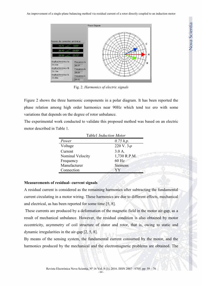
Fig. 2. Harmonics of electric signals
Figure 2 shows the three harmonic components in a polar diagram. It has been reported the
phase relation among high order harmonics near 90Hz which tend toz ero with some
variations that depends on the degree of rotor unbalance.
The experimental work conducted to validate this proposed method was based on an electric
motor described in Table 1.
Table1 Induction Motor Power 0.75 h.p. Voltage 220 V. 3ϕ Current 3.0 A. Nominal Velocity 1,730 R.P.M. Frequency 60 Hz Manufacturer Siemens Connection YY
Measurements of residual- current signals
A residual current is considered as the remaining harmonics after subtracting the fundamental
current circulating in a motor wiring. These harmonics are due to different effects, mechanical
and electrical, as has been reported for some time [5, 8].
These currents are produced by a deformation of the magnetic field in the motor air-gap, as a
result of mechanical unbalance. However, the residual condition is also obtained by motor
eccentricity, asymmetry of coil structure of stator and rotor, that is, owing to static and
dynamic irregularities in the air-gap [2, 5, 8].
By means of the sensing system, the fundamental current consumed by the motor, and the
harmonics produced by the mechanical and the electromagnetic problems are obtained. The

García-Reynoso, A. et al.
Revista Electrónica Nova Scientia, Nº 16 Vol. 8 (1), 2016. ISSN 2007 - 0705. pp: 59 – 76 - 65 -
Fourier spectrum of the signal is displayed and the mechanical unbalance is indirectly
determined by filtering the associated harmonics.
The measurement consists of a virtual instrument, a set of solid-state magnetic sensors and its
signal conditioning. It is designed for 220 volts and a maximum of 15 amperes. Voltage is
monitored through a set of transformers connected in star configuration with magnetic cores
that respond to a maximum of 10 kHz. The electric signal is obtained using Hall-effect probes
model M15 which have a range of 10 kHz.
Depending on harmonic order, there is an associated mechanical or electromagnetic problem.
Of particular interest is the harmonic signal related to mechanical unbalance. These harmonics
depend on the rotor slip, input frequency, and they occur at the frequencies given by the
following expressions:
h s rh f f= + (1)
l s rh f f= − (2)
Adjusting harmonics to remove offset
It may be observed, for harmonics of a balanced-rotor condition that the relative phase angles
among them ( )1 2 3, ,L L L have values of 120° (low frequency). However, when unbalance is
present these relative phase angles change due to the vector sum of the offset and the
unbalance effect.
Assuming that the three vectors ( )1 2 3, ,L L L are evenly distributed in the plane, 120° between
each other, when offset is subtracted ( )0 1 0 2 0 3, ,L L LR R R , with absolute phase angles that depend
on the unbalance, and considering the referential balanced-rotor condition with angular
positions 0 ,° 120° and 240° ( )1 2 3, ,B B B , respectively, vectors may look like is shown in Figure
3.

An improvement of a single-plane balancing method via residual current of a rotor directly coupled to an induction motor
Revista Electrónica Nova Scientia, Nº 16 Vol. 8 (1), 2016. ISSN 2007 - 0705. pp: 59 – 76 - 66 -
Fig. 3. Harmonic vectors
When direct measurements are included, vectors may look like shown in Figure 4 and their
equations are:
01 1 0 1LR B R= + (3)
02 2 0 2LR B R= + (4)
03 3 0 3LR B R= + (5)
Fig. 4. Composition of harmonic vectors
In order to obtain the absolute phase angles, the algorithm uses the relative phase angles among vectors 0 1 0 2 0 3, ,L L LP P P obtained by measurement. It then iterates until vectors
0 1 0 2 0 3, ,L L LR R R reach 120° between each other, satisfying the following conditions:
0 2 2
0 1 1
0 3 3
0 1 1
L
L
L
L
R BR BR BR B
=
= (6)

García-Reynoso, A. et al.
Revista Electrónica Nova Scientia, Nº 16 Vol. 8 (1), 2016. ISSN 2007 - 0705. pp: 59 – 76 - 67 -
There is a unique vector combination that fulfills this condition, and thus the absolute phase
angles are determined.
Traditional balancing
Having determined the harmonic phases, it is possible to calculate the influence coefficients
as well as the balance masses for each combination of trial weights. In the traditional method
of influence coefficients, formulas (7) and (8) provide a balance mass assuming the
magnitude and phase are known.
2
p
N NAW−
= (7)
cNWA
= − (8)
Proposed balancing method
From equations (3) and (4), it gets:
0 2 2 02
0 1 1 01
L
L
R B RR B R
− +=− +
(9)
Besides 1
01 01iR R e θ=
202 02
iR R e θ=
303 03
iR R e θ=
2 1 12θ θ θ= −
12 102 02
i iR R e eθ θ−=
Substitution in equation (9) yields the following result:
2 12 1
1
0 2 2 02
0 1 1 01
−− +=
− +
Bi i iL
iL
R B e R e eR B R e
θ θ θ
θ (10)
Let the following transformation:
1 01 1
1 01
ii
i
R B eeB R e
θθ
θ
′
′
+=
+ (11)
Substituting gives:
( ) '2 12 2 12
1 2 01 02 01 2 02 10 22 2
0 1 1 01
− −− + + − +=
− +
B Bi ii i i
L
L
B B e R R e R B e R B e eRR B R
θ θθ θ θ
(12)

An improvement of a single-plane balancing method via residual current of a rotor directly coupled to an induction motor
Revista Electrónica Nova Scientia, Nº 16 Vol. 8 (1), 2016. ISSN 2007 - 0705. pp: 59 – 76 - 68 -
This expression represents a circle with center at
2 121 2 01 02
2 21 01
Bi iB B e R R eCB R
θ θ−− +=
− +
And the radius is:
2 1201 2 02 1
2 21 01
Bi iR B e R B eRB R
θ θ−− +=
− +
The circle ReiC θ ′+ represents the geometric locus of all possible relations 0 2 0 1L LR R and the
correct value ( )22 3
1
−iB eB
π must be on the circumference.
Similarly there is another circle ReiC θ ′′+ which represents the geometric locus of all possible
relations 0 3 0 1L LR R and the correct value ( )23 3
1
iB eB
π must be on the circumference.
If errors are present, harmonics must be adjusted by the following perturbations:
( )01 01 11R R ε= +
( )02 02 21R R ε= +
( )03 03 31R R ε= +
12 12 1θ θ δ= +
13 13 2θ θ δ= +
2 2 2 2 21 2 3 1 2S ε ε ε δ δ= + + + + (13)
Next, a set of relations involving perturbations is developed: from equation (12), equating the
right side to the correct relation yields:
( ) ( )2 12 2 12
21 2 01 02 01 2 02 1 2 32 2
1 01 1
B Bi ii i iiB B e R R e R B e R B e e B e
B R B
θ θθ θ θπ
− ′− − −−− + + − +
=− +
(14)
This means that there must be a parameter θ ′ that corresponds to the correct point. This is a
compatibility condition for harmonics related with 1 2,L L .
By expressing this equation in rectangular form, it is obtained the following:
( ) ( )' 'cos sin+ − = +a ib i c idθ θ
Equating the real and imaginary parts of both sides of last equation, one gets:
cos sinsin cos
′ ′+ =′ ′− + =
a b ca b d
θ θθ θ
(15)
Solving this system of equations yields:

García-Reynoso, A. et al.
Revista Electrónica Nova Scientia, Nº 16 Vol. 8 (1), 2016. ISSN 2007 - 0705. pp: 59 – 76 - 69 -
2 2sin −′ =+
bc ada b
θ (16)
2 2cos +′ =+
ac bda b
θ (17)
Substituting in the trigonometric identity that the sum of the squares is equal to one, one gets: 2 2
2 2 1c da b+
=+
Substituting these coefficients the following expression is obtained:
( )
( ) ( )( ) ( )
2 22 2 2 2 2 2 2 2 2 2201 2 02 1 2 01 02 01 12
122 2 2
2 01 1 2
2 2201 02 01 1 12
1
22 cos 3
22 cos 03
+ − − − −
− − +
+ − + =
B
BR B R B B B R R R BB
B R B
B R R R BB
πθ
πθ
(18)
Similarly, for the circle corresponding to θ ′′ the following are obtained:
2 2sin′ ′ ′ ′−′′ =′ ′+
b c a da b
θ (19)
2 2cos′ ′ ′ ′+′′ =′ ′+
a c b da b
θ (20)
( )
( ) ( )( ) ( )
3
2 2 2 2 2 2 2 201 3 03 1 1 3 01 03
2 22 2301 12
1
2 2 23 01 1
2 2301 03 01 1 13
1
22B cos 3
22 cos 03
B
R B R B B B R RB R BB
R B
B R R R BB
πθ
πθ
+ − −
− −
− − −
+ − + =
(21)
In order to satisfy (18) and (21), which impliesθ θ′ ′′= , ie. sin sinθ θ′ ′′= , it is necessary to
adjust all parameters involved by means of small perturbations leading to (22), where ih are
not described here for lack of space. By similar procedure, for the relation, cos cosθ θ′ ′′= we
obtain equation (23)
1 0 1 2 2 3h h hε ε ε= + + (22)
1 0 1 2 2 3ε η η ε η ε= + + (23)
Similarly, equations (18) and (21) are worked out to satisfy themselves by perturbing the
harmonics to finally obtain (24) and (25).
1 0 1 1 2 2d d dδ ε ε= + + (24)
2 0 1 1 2 2d d dδ ε ε′ ′ ′= + + (25)
An improvement of a single-plane balancing method via residual current of a rotor directly coupled to an induction motor
Revista Electrónica Nova Scientia, Nº 16 Vol. 8 (1), 2016. ISSN 2007 - 0705. pp: 59 – 76 - 70 -
Since the parameter θ ′ is going to vary in an iterative process, the following constant is
defined: '=tpS sinθ and it is substituted in equation (16) and harmonics are perturbed to get
equation (26).
1 1 2 2 3 1 0 0q q q qε ε δ+ + + = (26)
Similarly, we define tpC =cosθ' , substitute in equation (17) and apply perturbations to obtain
(27).
1 1 2 2 3 1 0oq q q qε ε δ′ ′ ′ ′+ + + = (27)
Equating (22) and (23) one gets:
2 20 21 2t tε ε= + (28)
Substitution of equation (28) in (22) gives:
1 10 11 2t tε ε= + (29)
Substitution of equation (28) and (29) in (25) gives:
2 40 41 2t tδ ε= + (30)
Substitution of equation (29) in (24) gives:
1 30 31 2t tδ ε= + (31)
Thus all perturbations are expressed in terms of 2ε .
These are substituted in equations (26) and (27) to obtain two expressions for 2ε :
( )0 1 10 3 302
1 11 2 3 31
q q t q tq t q q t
ε− + +
=+ +
(32)
( )0 1 10 3 302
1 11 2 3 31
q q t q tq t q q t
ε′ ′ ′− + +
=′ ′ ′+ +
(33)
In the iterative process, when the parameters ,θ θ′ ′′ approach each other, so do both values of
2ε given by equations (32) and (33). At the end, the desired solution is obtained for the given
value ofθ ′ .
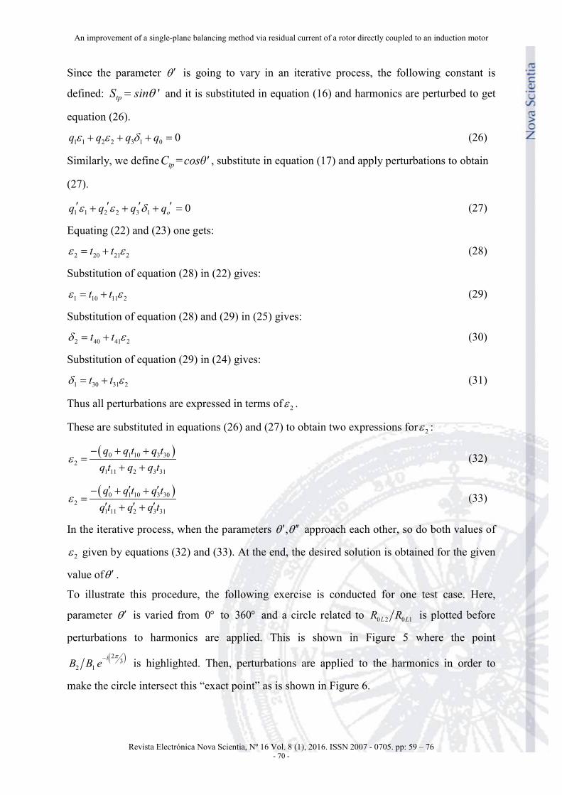
To illustrate this procedure, the following exercise is conducted for one test case. Here,
parameter θ ′ is varied from 0° to 360° and a circle related to 0 2 0 1L LR R is plotted before
perturbations to harmonics are applied. This is shown in Figure 5 where the point
( )23
2 1−iB B e
π is highlighted. Then, perturbations are applied to the harmonics in order to
make the circle intersect this “exact point” as is shown in Figure 6.

García-Reynoso, A. et al.
Revista Electrónica Nova Scientia, Nº 16 Vol. 8 (1), 2016. ISSN 2007 - 0705. pp: 59 – 76 - 71 -
Fig. 5. Circle before data perturbations
Fig. 6. Circle after data perturbations
As it may be seen, perturbations are enforcing data to fulfill compatibility conditions by
making the circle pass over the “exact point”. Something similar applies to the other circle of
0 3 0 1L LR R and its “exact point” ( )23
3 1iB B e
π.

An improvement of a single-plane balancing method via residual current of a rotor directly coupled to an induction motor
Revista Electrónica Nova Scientia, Nº 16 Vol. 8 (1), 2016. ISSN 2007 - 0705. pp: 59 – 76 - 72 -
To determine which θ′ to use for this rotor balancing, either for the original balance run or for
the trial mass run, the following analysis is performed.
The inertia force due to the unbalance mass plus the trial mass is the resultant:
p d dpW W W→ → →
+ =
By taking the real and imaginary parts of this vector equation one gets:
cos cos cos 0+ − =p p d d dp dpW W Wθ θ θ
sin sin sin 0+ − =p p d d dp dpW W Wθ θ θ
This may be written in a matrix form:
cos cos cossin sin sin
d dp d p p
d dp dp p p
W WW W
θ θ θθ θ θ
− −=
− − (34)
Given the unbalance and resultant angles (according to the iterations), and the trial mass, the
magnitudes of the unbalance mass and the resultant may be solved as follows:
( )( )( )
sin
sin sin
dp pd p
dp d dp d p
W WW
θ θ
θ θ θ θ
−=
− − (35)
The angle of transformation for the original unbalanced condition0
θ ′ , and the corresponding
angle for the trial mass run ′θ are related to the resultant angle by equation (36):
0 dpθ θ θ′ ′− = (36)
Equations (35) and (36) provide another compatibility condition that allows the determination
of the desired solution to the balancing problem.
Algorithm description
The numerical procedure consists of the following steps:
1. It initiates the iteration cycle for the parameter 0θ ′ corresponding to the original
unbalance. It then calculates the harmonics 0 1 0 2 0 3, ,L L LR R R were offset has been
subtracted. This is done according to the perturbations that converge when the two
values of 2ε approach each other in a cycle that minimizes function given by equation
(9).
2. It initiates another iteration cycle for the parameter θ ′ corresponding to the trial mass
run. It then calculates the harmonics 01 02 03, ,R R R related to the resultant unbalance.
This is performed in a similar way as the previous step.

García-Reynoso, A. et al.
Revista Electrónica Nova Scientia, Nº 16 Vol. 8 (1), 2016. ISSN 2007 - 0705. pp: 59 – 76 - 73 -
3. Once the harmonics are known, it then calculates the influence coefficients and the
balance masses.
4. It initiates an iteration cycle for the unbalance angle, calculating then the unbalance
mass according to equation (35). Iteration is done until it finds the best approximation
to the unbalance mass obtained previously in step 3.
5. It recycles iteration to step 2.
6. It recycles iteration to step 1. At the end, it brings out the optimal solution of the
parameters, and the desired balance mass.
Applications
Several tests were conducted using an induction motor described in Table 1. Recorded data
using the virtual instrument described above are shown in Tables 2 and 3. Table 4 shows
estimated balance masses for each test case to compare with the expected value.
These test results show that balance mass approaches the expected value with an error of less
than 10% in magnitude and with +/- 10° error in angular position.
Table 2 Harmonic values of test runs, mA, high frequency hh .
Case C- 90Hz L1 L2 L3
4.3g ∠45° 89.1575 64.4496 117.4634 4.3g ∠90° 63.7376 49.7091 96.2146 4.3g ∠135° 41.5683 29.2256 69.4842 4.3g ∠180° 41.3958 12.3781 51.6063 4.3g ∠225° 58.5760 4.6720 54.1722 4.3g ∠270° 82.6952 28.7914 80.0129 4.3g ∠315° 102.2546 55.2800 111.2583 Original unbalance 8.0g ∠0° 65.8141 25.6717 79.4410 Balanced Rotor 28.5225 27.2468 33.2415
Table 3 Harmonic values of relative phase angle Θ, high frequency hh .
Case C- 90Hz Θ12 Θ13 Θ32
4.3g ∠45° 158.46 -93.94 -107.60 4.3g ∠90° 175.80 -88.75 -95.45 4.3g ∠135° -144.74 -71.03 -73.71 4.3g ∠180° -79.31 -50.67 -28.64 4.3g ∠225° 106.03 -63.67 -190.30 4.3g ∠270° 138.02 -80.65 -141.32

An improvement of a single-plane balancing method via residual current of a rotor directly coupled to an induction motor
Revista Electrónica Nova Scientia, Nº 16 Vol. 8 (1), 2016. ISSN 2007 - 0705. pp: 59 – 76 - 74 -
4.3g ∠315° 145.01 -90.50 -124.49 Original unbalance 8.0g ∠0° 174.85 -77.62 -107.53 Balanced Rotor -11.44 -5.68 -5.7551
Table 4 Balance masses (g) for test cases Case Balance Mass
4.3g ∠45° 7.90g ∠187.7° 4.3g ∠90° 8.08g ∠176.8° 4.3g ∠180° 8.84g ∠181.3° 4.3g ∠225° 8.31g ∠182.2° 4.3g ∠270° 8.48g ∠189.8° 4.3g ∠315° 8.08g ∠187.8° Expected mass 8.00g ∠180°
As is well known in rotor balancing, vibration data is subject to random errors which make
the first balancing exercise not precise enough in terms of fulfilling the vibration standards for
the particular rotor in turn. Normally, it is necessary to conduct a second exercise called
“trimming” that reduces any residual unbalance.
The balance technique that is presented here is unique in handling residual current as input
data, and it is also subject to measurement errors. The test cases show the first balancing
exercise where the estimated balance masses have relatively small errors similar to the ones
obtained in traditional practice.
Conclusions
1. Based on previous works in the literature, where a relationship between the
mechanical unbalance and the electric-current harmonics is reported, this article develops a
more efficient method of balancing that takes into account the r.m.s. values of these
harmonics and the relative phase angles among the three frequency lines.
2. This balancing technique faces two problems; one is data variations of samples which
are solved by taking three to five minute samplings, and calculating the r.m.s. value of the
response. The other difficulty is nonlinearity behavior of data due to an offset.
3. The magnitudes of the signal spectrum do not have a linear homogeneous
relationship with the unbalance force due to a complex offset that can be measured with the
balanced rotor, and that adds to the unbalance effects. These vectors are measured in
magnitude, and their measured phase angles are relative.

García-Reynoso, A. et al.
Revista Electrónica Nova Scientia, Nº 16 Vol. 8 (1), 2016. ISSN 2007 - 0705. pp: 59 – 76 - 75 -
4. The harmonics of the balanced-rotor condition are determined in magnitude, and their
phase angles are set to 0° , 120− ° y 240− ° for the corresponding line frequency Li, in the case
of low frequency ( lh ). For high frequency ( hh ) the relative angles are set to 0° .
5. The harmonics related to the unbalance condition (vectors 0 1LP , 0 2LP and 0 3LP ) have an
absolute phase that is iteratively calculated depending on the parameter 1α , which is the
absolute phase angle of line 1L and taking into account the relative phase with the other
frequency lines.
6. The numerical procedure consists of iterations of angles of transformation 0θ ′ andθ′ ,
and perturbing the harmonics to satisfy the compatibility conditions. In the end, one obtains a
solution for the minimum sum of squares of the perturbations.
7. The test cases show that the calculated balance mass approaches the expected value
with an error of less than 10% in magnitude and with 0 10θ ′ ± ° error in angular position.
8. The virtual instrument developed in this work offers a low cost and a user-friendly
interface, and thus a remarkable potential for industrial applications.
References
[1] Dorrell D. G., W. T. Thomson, and S. Roach. (1995). Analysis Of Airgap Flux, Current
And Vibration Signals As A Function Of The Combination Of Static And Dynamic
Airgap Eccentricity In 3 Phase Induction Motors. IAS 95 Conference Record Of The
1995 IEEE Industry Applications Conference Vol. 1 pp 563-70, 1995.
[2] Riley, C.M., Lin B.K., Habetler T.G and Kliman G.B. (1997). Stator Current Based
Sensorless Vibration Monitoring Of Induction Motors Applied Power Electronics
Conference And Exposition 1997, Vol 1, pp 142-147, 1997.
[3] Riley C.M., Brian K. Lin, and Thomas G. Habetler. (1998). A Method For Sensorless On-
Line Vibration Monitoring Of Induction Machines. IEEE Transactions On Industry
Applications, Vol. 34, No. 6, 1998.
[4] Riley C.M., Brian K. Lin, and Thomas G. Habetler. (1999). Stator Current Harmonics
And Their Causal Vibrations: A Preliminary Investigation Of Sensorless Vibration
Monitoring Applications. IEEE Transaction On Industry Applications, Vol. 35 No. 1,
1999.

An improvement of a single-plane balancing method via residual current of a rotor directly coupled to an induction motor
Revista Electrónica Nova Scientia, Nº 16 Vol. 8 (1), 2016. ISSN 2007 - 0705. pp: 59 – 76 - 76 -
[5] Finley W, Hodowanec M., and Holter W. (2000). An Analytical Approach To Solving
Motor Vibration Problems. IEEE Transaction On Industry Applications Vol. 36 No. 5,
2000.
[6] Kral C., Haebetler T., and Harley R. (2004). Detection Of Mechanical Imbalance Of
Induction Machines Without Spectral Analysis Of Time Domain Signals. IEEE
Transaction On Industry Applications Vol. 40 No 4, 2004.
[7] Neelam M., and Dahiya R. (2007). Motor Current Signature Analysis And Its
Applications In Induction Motor Fault Diagnosis. International Journal Of Systems
Applications, Engineering & Development. Vol 2, Issue 1, 2007.
[8] Bellini A., Filippeti F., Tassoni C., and Capolino G. A. (2008). Advances in Diagnostic
Techniques for Induction Machines. IEEE Transactions on industrial electronics Vol. 55
No 12 Dec. 2008.
[9] Camargo M. J, García R. A., Ladrón de Guevara D. E., Hernández M. E. Balanceo
Dinámico De Motores De Inducción Utilizando Componentes De Corriente Eléctrica. XV
Congreso Internacional Anual de la SOMIM, Instituto Tecnológico Superior de Cajeme,
Cd. Obregón, Son., 23, 24 y 25 de Septiembre, 2009, No. de registro: A4_21.
[10] Duque-Pérez, O., García-Escudero,L.A., Morinigo-Sotelo, D., Gardel P.E., Pérez-Alondo,
M., Analysis of Fault Signatures for the Diagnosis of Induction Motors Fed by Voltage
Souce Inverters Using ANOVA and Additive Models, Electric Power Systems Research
04/2015; 121, pages 1-13.
[11] García-Reynoso, A., Ladrón de Guevara D. E., García P., Alfonso, Lorandi M., Alberto
P., Hermida S., Guillermo (2013). Single-Plane Balancing of a Rotor Directly Coupled an
Induction Motor by Using Residual Current. European International Journal of Science
and Technology, Vol. 2, No. 5, June 2013, ISNN 2304-9693, pp 140-150.
[12] García-Reynoso, A., Ladrón de Guevara D. E., García P., Alfonso, Lorandi M., Alberto
P., Hermida S., Guillermo (2013). Phase Determination of Harmonic Components of
Current Associated to Mechanical Unbalanced Rotors while Coupled to an Induction.
European International Journal of Science and Technology, Vol. 2, No. 8, October 2013,
ISNN 2304-9693, pp 89-103.


![203001710 Balanceo Aurara Fiber Deep[1]](https://img.pdfslide.us/doc/110x75/55cf9427550346f57b9ff63f/203001710-balanceo-aurara-fiber-deep1.jpg)