Embed Size (px)
Citation preview
Security Level 2 Electronic documents, once printed, are non-controlled and may become outdated.
Refer to the Electronic Document Management System for the current revision. © Bechtel Oil, Gas & Chemicals, Inc. 2013. All rights reserved.
25585-500-G01-GHX-00094 Page 2 of 83 Revision 002
Commissioning Environmental Management Plan
REVISIONS, DISTRIBUTION AND CONSULTATION
The development of this Commissioning Environmental Management Plan (CEMP) has
been compiled, revised and distributed in the consultation of internal and external
stakeholders, including:
Revision Stakeholder In consultation of Date
000 QGC QGC 26.08.2013
001 QGC QGC 29.10.2013
002
This procedure shall be revised and amended in accordance with the consultation and
collaboration requirements of relevant Stakeholders. This plan is intended to be a working
document and will be subject to periodic audit and review. Amendment will only be made to
reflect changes in project requirements or to correct any disparity identified during project
review or auditing.
Any comments, complaints and improvements regarding this document should be forwarded
to this CEMP’s Sponsor. If the text or body of this CEMP is required to be updated at any
stage during the operations, a revised copy will be submitted relevant agencies with a
consultation or approval role.
Security Level 2 Electronic documents, once printed, are non-controlled and may become outdated.
Refer to the Electronic Document Management System for the current revision. © Bechtel Oil, Gas & Chemicals, Inc. 2013. All rights reserved.
25585-500-G01-GHX-00094 Page 3 of 83 Revision 002
Commissioning Environmental Management Plan
TABLE OF CONTECTS
1. INTRODUCTION AND SCOPE ..................................................................... 12
1.1. PROJECT BACKGROUND ........................................................................... 14
1.2. APPROVALS, PERMITS AND LEGISLATION .............................................. 15
1.2.1. Environmental Authority ................................................................................ 15
1.2.2. Other permits ................................................................................................. 15
1.2.3. Legislative Framework, Industry Standards and Guidelines ......................... 15
1.3. RELATED DOCUMENTATION ..................................................................... 15
1.4. PLAN STRUCTURE ...................................................................................... 16
2. DESCRIPTION OF LNG PLANT PROCESS ................................................ 17
2.1. LNG PLANT PROCESS ................................................................................ 17
2.1.1. Composition of gas ........................................................................................ 18
2.1.2. Inlet Separation (Unit 11) .............................................................................. 18
2.1.3. Acid Gas Removal (Unit 12) .......................................................................... 18
2.1.4. Dehydration (Unit 13) .................................................................................... 19
2.1.5. Mercury Removal (Unit 13)............................................................................ 19
2.1.6. Liquefaction (Units 14, 15 & 16) .................................................................... 19
2.1.7. LNG Storage (Unit 24) ................................................................................... 19
2.1.8. LNG Jetty and ship loading ........................................................................... 20
2.1.9. Utilities ........................................................................................................... 20
2.1.9.1. Flare and Relief System (Unit 19) ............................................................ 20
2.1.9.2. Diesel Storage and Transfer .................................................................... 21
2.1.9.3. Power Generation .................................................................................... 21
2.1.9.4. Plant and Instrument Air (Unit 35) and Nitrogen (Unit 39)........................ 21
2.1.9.5. Firewater Systems (Units 33) ................................................................... 22
2.1.9.6. Fuel Gas ................................................................................................... 22
2.1.9.7. Hot Oil System (Unit 34) .......................................................................... 22
Security Level 2 Electronic documents, once printed, are non-controlled and may become outdated.
Refer to the Electronic Document Management System for the current revision. © Bechtel Oil, Gas & Chemicals, Inc. 2013. All rights reserved.
25585-500-G01-GHX-00094 Page 4 of 83 Revision 002
Commissioning Environmental Management Plan
2.1.9.8. Refrigerant Storage .................................................................................. 23
2.2. ASSOCIATED INFRASTRUCTURE ............................................................. 23
2.2.1. Water Supply, Management and Storage ..................................................... 23
2.2.1.1. Potable Water .......................................................................................... 23
2.2.1.2. Water treatment system (Unit 36) ............................................................ 23
2.2.1.3. Stormwater Management (non-process areas) ........................................ 23
2.2.2. Waste water and effluent management ......................................................... 24
2.2.3. Amine and Hot Oil Drainage .......................................................................... 24
2.3. OTHER CSU ACTIVITY ................................................................................ 25
2.3.1. Lube oil flushing ............................................................................................ 25
2.3.2. Chemical cleaning ......................................................................................... 25
2.3.3. Degreasing of the Acid Gas Removal Unit .................................................... 25
2.3.4. Materials Storage and Handling .................................................................... 25
2.3.5. Waste Management ...................................................................................... 26
2.3.6. Dangerous Goods and Hazardous Substance Handling ............................... 27
2.4. CONSTRUCTION PHASE ACTIVITIES DURING COMMISSIONING .......... 28
3. OVERALL ENVIRONMENTAL MANAGEMENT APPROACH ..................... 30
3.1. PERFORMANCE CRITERIA ......................................................................... 30
3.2. ENVIRONMENTAL POLICIES ...................................................................... 30
3.2.1. QGC Environmental Policy ............................................................................ 30
3.2.2. Bechtel Environmental Policy ........................................................................ 30
4. ENVIRONMENTAL CONDITIONS AND VALUES ........................................ 31
4.1. CLIMATIC CONDITIONS .............................................................................. 31
4.2. SENSITIVE RECEPTORS (NOISE, VIBRATION AND AIR QUALITY) ........ 31
4.3. VISUAL (LIGHTING) ..................................................................................... 33
4.4. ECOLOGY ..................................................................................................... 33
Security Level 2 Electronic documents, once printed, are non-controlled and may become outdated.
Refer to the Electronic Document Management System for the current revision. © Bechtel Oil, Gas & Chemicals, Inc. 2013. All rights reserved.
25585-500-G01-GHX-00094 Page 5 of 83 Revision 002
Commissioning Environmental Management Plan
4.5. GROUNDWATER ......................................................................................... 35
4.6. SURFACE WATER ....................................................................................... 35
4.7. MARINE WATER .......................................................................................... 35
5. CSU ACTIVITIES, POTENTIAL ENVIRONMENTAL IMPACTS AND ASSOCIATED MANAGEMENT ............................................................................... 36
5.1. AIR QUALITY MANAGEMENT ..................................................................... 39
5.1.1. Performance criteria ...................................................................................... 40
5.1.2. Point Source Air Emissions ........................................................................... 42
5.1.2.1. CSU Flaring .............................................................................................. 42
5.1.2.2. CSU of gas turbines, hot oil heater and regeneration gas heater ............ 43
5.1.2.3. AGRU ....................................................................................................... 46
5.1.3. Fugitive Emissions ........................................................................................ 46
5.2. NOISE ........................................................................................................... 48
5.2.1. Performance criteria ...................................................................................... 48
5.2.2. Point Source Noise emissions ....................................................................... 48
5.2.2.1. Flaring ...................................................................................................... 48
5.2.2.2. Pipe air blowing ........................................................................................ 50
5.3. WATER AND WASTEWATER MANAGEMENT ........................................... 51
5.3.1. Performance criteria ...................................................................................... 52
5.3.2. Stormwater from process areas and discharge from the water treatment facility 53
5.3.3. Sewage Effluent ............................................................................................ 56
5.3.4. Stormwater (non-process area) ..................................................................... 56
5.3.5. Groundwater .................................................................................................. 57
5.3.6. Loading of LNG carriers at jetty ..................................................................... 57
5.4. DANGEROUS GOODS AND HAZARDOUS SUBSTANCES ....................... 58
5.4.1. Hazardous Substances Management and Storage ....................................... 59
5.4.2. Spill Management .......................................................................................... 61
Security Level 2 Electronic documents, once printed, are non-controlled and may become outdated.
Refer to the Electronic Document Management System for the current revision. © Bechtel Oil, Gas & Chemicals, Inc. 2013. All rights reserved.
25585-500-G01-GHX-00094 Page 6 of 83 Revision 002
Commissioning Environmental Management Plan
5.4.2.1. Spill Response ......................................................................................... 61
5.4.2.2. Spill Cleanup Actions ............................................................................... 62
5.5. WASTE MANAGEMENT ............................................................................... 63
5.5.1. Collection and Handling ................................................................................ 64
5.5.2. Storage and Handling .................................................................................... 64
5.5.3. Transportation of Waste ................................................................................ 64
5.5.4. Monitoring of Waste ...................................................................................... 64
5.5.4.1. Waste Tracking ........................................................................................ 65
5.5.4.2. Waste Disposal ........................................................................................ 66
5.5.5. Non-hazardous Wastes ................................................................................. 66
5.5.6. Hazardous Waste .......................................................................................... 66
5.6. LIGHTING ..................................................................................................... 67
5.7. PESTS AND MOSQUITO’S .......................................................................... 68
5.8. FLORA AND FAUNA MANAGEMENT .......................................................... 68
6. GENERAL ENVIRONMENTAL MANAGEMENT .......................................... 69
6.1. ENVIRONMENTAL EMERGENCY PREPAREDNESS ................................. 69
6.2. INTEGRATED CONTROL AND SAFETY SYSTEM ..................................... 69
6.3. ENVIRONMENTAL INCIDENTS ................................................................... 71
6.4. JOB HAZARD ANALYSIS ............................................................................. 72
6.4.1. Site Environmental Plan ................................................................................ 72
6.5. STRUCTURE AND RESPONSIBILITIES ...................................................... 72
6.5.1. Queensland Gas Company (QGC)................................................................ 73
6.5.2. Bechtel .......................................................................................................... 73
6.5.2.1. Senior Project Manager ........................................................................... 74
6.5.2.2. Site Manager ............................................................................................ 74
6.5.2.3. Health, Safety, Security and Environmental Manager ............................. 74
Security Level 2 Electronic documents, once printed, are non-controlled and may become outdated.
Refer to the Electronic Document Management System for the current revision. © Bechtel Oil, Gas & Chemicals, Inc. 2013. All rights reserved.
25585-500-G01-GHX-00094 Page 7 of 83 Revision 002
Commissioning Environmental Management Plan
6.5.2.4. Environmental Services Manager ............................................................ 74
6.5.2.5. Environmental Inspectors ......................................................................... 75
7. PROGRAMMES AND PROCEDURES ......................................................... 76
7.1. AWARENESS, TRAINING AND COMPETENCY ......................................... 76
7.2. COMMUNICATIONS ..................................................................................... 76
8. ENVIRONMENTAL PROCEDURES AND FORMS ...................................... 77
8.1. ENVIRONMENTAL INSPECTION ................................................................. 77
8.2. ENVIRONMENTAL AUDITING ..................................................................... 78
8.3. NON-CONFORMITY, INVESTIGATION AND PREVENTIVE ACTION ........ 78
8.4. DOCUMENT CONTROL AND RECORDS .................................................... 78
8.5. CONTINUAL IMPROVEMENT ...................................................................... 79
8.6. REVIEW ........................................................................................................ 79
APPENDIX A - LEGISLATION, INDUSTRY STANDARDS AND GUIDELINES ..... 80
APPENDIX B - ENVIRONMENTAL POLICIES ....................................................... 82
QGC HSSE POLICY ................................................................................................ 82
BECHTEL ENVIRONMENTAL POLICY .................................................................. 83
Security Level 2 Electronic documents, once printed, are non-controlled and may become outdated.
Refer to the Electronic Document Management System for the current revision. © Bechtel Oil, Gas & Chemicals, Inc. 2013. All rights reserved.
25585-500-G01-GHX-00094 Page 8 of 83 Revision 002
Commissioning Environmental Management Plan
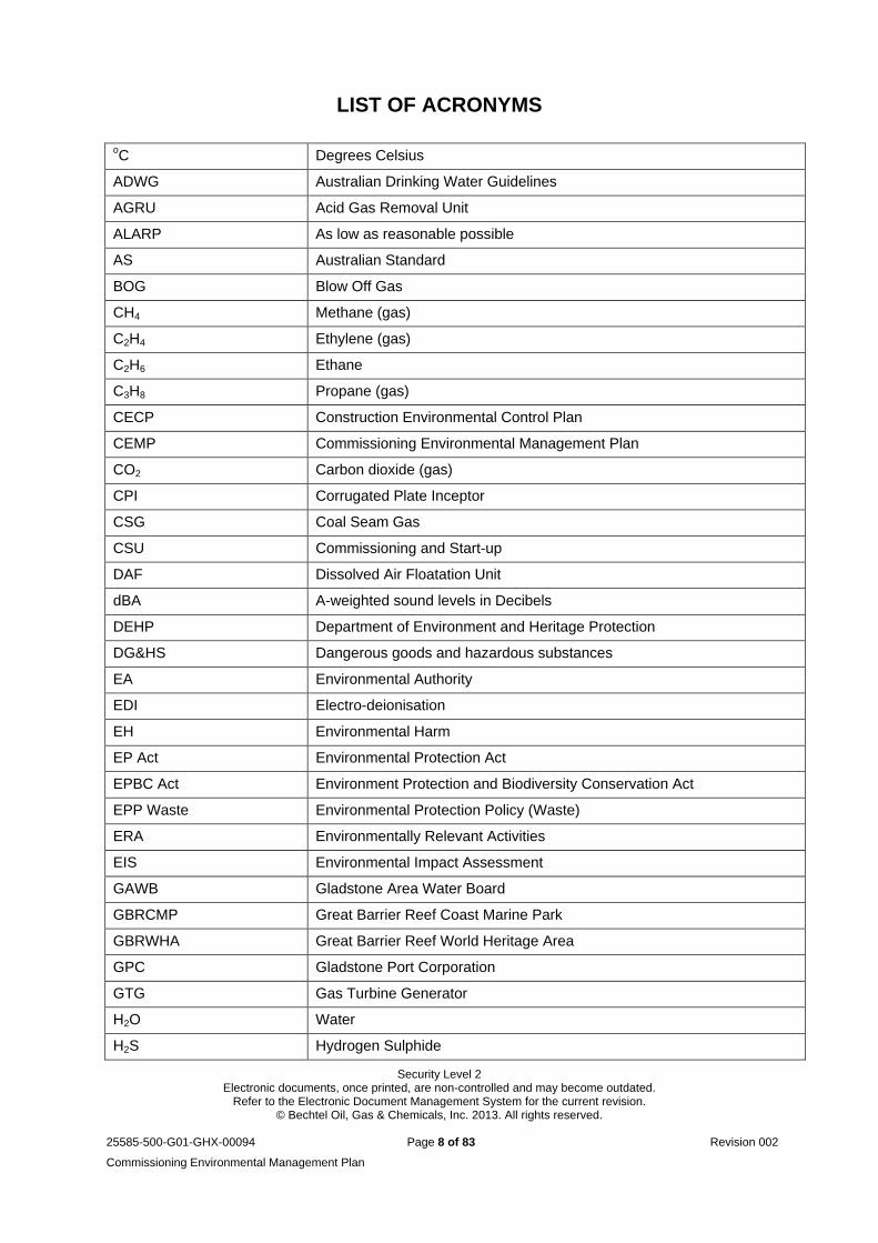
LIST OF ACRONYMS
oC Degrees Celsius
ADWG Australian Drinking Water Guidelines
AGRU Acid Gas Removal Unit
ALARP As low as reasonable possible
AS Australian Standard
BOG Blow Off Gas
CH4 Methane (gas)
C2H4 Ethylene (gas)
C2H6 Ethane
C3H8 Propane (gas)
CECP Construction Environmental Control Plan
CEMP Commissioning Environmental Management Plan
CO2 Carbon dioxide (gas)
CPI Corrugated Plate Inceptor
CSG Coal Seam Gas
CSU Commissioning and Start-up
DAF Dissolved Air Floatation Unit
dBA A-weighted sound levels in Decibels
DEHP Department of Environment and Heritage Protection
DG&HS Dangerous goods and hazardous substances
EA Environmental Authority
EDI Electro-deionisation
EH Environmental Harm
EP Act Environmental Protection Act
EPBC Act Environment Protection and Biodiversity Conservation Act
EPP Waste Environmental Protection Policy (Waste)
ERA Environmentally Relevant Activities
EIS Environmental Impact Assessment
GAWB Gladstone Area Water Board
GBRCMP Great Barrier Reef Coast Marine Park
GBRWHA Great Barrier Reef World Heritage Area
GPC Gladstone Port Corporation
GTG Gas Turbine Generator
H2O Water
H2S Hydrogen Sulphide
Security Level 2 Electronic documents, once printed, are non-controlled and may become outdated.
Refer to the Electronic Document Management System for the current revision. © Bechtel Oil, Gas & Chemicals, Inc. 2013. All rights reserved.
25585-500-G01-GHX-00094 Page 9 of 83 Revision 002
Commissioning Environmental Management Plan
Hg+ Mercury
HSSE Health, Safety, Security and Environment
JHA Job Hazard Analysis
ICSS Integrated Control and Safety System
ISBL Inside battery limits
LNG Liquefied Natural Gas
MNES Matters of National Environmental Significance
N2 Nitrogen (gas)
NEPM Air National Environmental Protection Measure
NOx Oxides of Nitrogen
NRU Nitrogen Rejection Units
PASCS Process Area Spill Containment Sump
PIG Pipeline Inspection Gauge
PFL Petroleum Facility Licence
PM Particulate matter
QCLNG Queensland Curtis Liquefied Natural Gas
QGC Queensland Gas Company
RO Reverse osmosis
sEIS Supplementary Environmental Impact Statement
SEPs Site Environmental Plans
SimOp Simultaneous operation
TCCC Time of care, custody and control
TCF Temporary camp facility
VOCs Volatile organic compounds
WHR Waste Heat Recovery
WMS Work Method Statement
Security Level 2 Electronic documents, once printed, are non-controlled and may become outdated.
Refer to the Electronic Document Management System for the current revision. © Bechtel Oil, Gas & Chemicals, Inc. 2013. All rights reserved.
25585-500-G01-GHX-00094 Page 10 of 83 Revision 002
Commissioning Environmental Management Plan
DEFINITIONS
Administering
Authority
An authority with legislative jurisdiction
Best Practice
Environmental
Management
The management of the activity to achieve an ongoing minimisation of the
activity’s environmental harm through cost-effective measures assessed
against the measures currently used nationally and internationally for the
activity (s21, EP Act 1994)
Contamination incident Contamination incident means an incident involving contamination of the
environment, that the administering authority is satisfied has caused or is
likely to cause serious or material environmental harm.
Control Measure Control measure means a device, equipment, structure, or management
strategy used to prevent or control the release of a contaminant or waste to
the environment. Examples include:
• an acoustic enclosure
• a bund around a storage pond
• a release or overflow valve on machinery
• a strategy for operating a furnace in a way that achieves combustion of a
contaminant at a particular oxygen level
Dangerous Goods Dangerous goods class means the class allocated to dangerous goods under
the seventh edition of the ‘Australian Code for the Transport of Dangerous
Goods by Road and Rail’.
Environmental
Aspect
An element of the surrounding environment requiring specific environmental
management and/or consideration.
Environmental Harm Environmental harm is any adverse effect, or potential adverse effect
(whether temporary or permanent and of whatever magnitude, duration or
frequency) on an environmental value, and includes environmental nuisance.
Environmental
Nuisance
Environmental nuisance is unreasonable interference or
likely interference with an environmental value caused by—
(a) aerosols, fumes, light, noise, odour, particles or smoke; or
(b) an unhealthy, offensive or unsightly condition because of contamination;
or
(c) another way prescribed by regulation.
Security Level 2 Electronic documents, once printed, are non-controlled and may become outdated.
Refer to the Electronic Document Management System for the current revision. © Bechtel Oil, Gas & Chemicals, Inc. 2013. All rights reserved.
25585-500-G01-GHX-00094 Page 11 of 83 Revision 002
Commissioning Environmental Management Plan
Environmental Value Environmental Value is a quality or physical characteristic of the environment
that is conducive to ecological health, public amenity or safety, or declared to
be a value under legislation.
Licensed Waste
Transporter
Approved waste transporter means a person who removes, collects or
transports waste under an approval from a local government under section
369A of the EP Act 1994.
Monitoring Monitoring, in relation to monitoring the impact of an activity on the receiving
environment, includes analysing, assessing, examining, inspecting,
measuring, modeling or reporting any of the following—
(a) the quantity, quality, characteristics, timing and variability of the release of
the contaminant;
(b) the effectiveness of control measures;
(c) characteristics of, and impact on, the receiving environment;
(d) the effectiveness of remedial or rehabilitation measures.
Regulated Waste Regulated waste means regulated waste within the meaning of the
Environmental Protection Regulation 2008.
Release Release, of a contaminant into the environment, includes - Schedule 4 of EP
Act 1994:
(a) to deposit, discharge, emit or disturb the contaminant; and
(b) to cause or allow the contaminant to be deposited, discharged emitted or disturbed; and
(c) to fail to prevent the contaminant from being deposited, discharged, emitted or disturbed; and
(d) to allow the contaminant to escape; and
(e) to fail to prevent the contaminant from escaping.
Sensitive Receptor Sensitive Receptor means a sensitive receptor under any relevant
environmental protection policies.
Spill A minor spill is defined as a spill where:
The amount or nature of the released/potentially released substance cannot cause serious harm to community health or the environment.
A major spill is defined as a spill where:
The amount or toxic nature of the substances released / potentially released can cause serious harm to community health or the environment
Trackable waste Trackable waste is as per the definition of Section 17 of the Environmental Protection (Waste Management) Regulation 2000.
Security Level 2 Electronic documents, once printed, are non-controlled and may become outdated.
Refer to the Electronic Document Management System for the current revision. © Bechtel Oil, Gas & Chemicals, Inc. 2013. All rights reserved.
25585-500-G01-GHX-00094 Page 12 of 83 Revision 002
Commissioning Environmental Management Plan
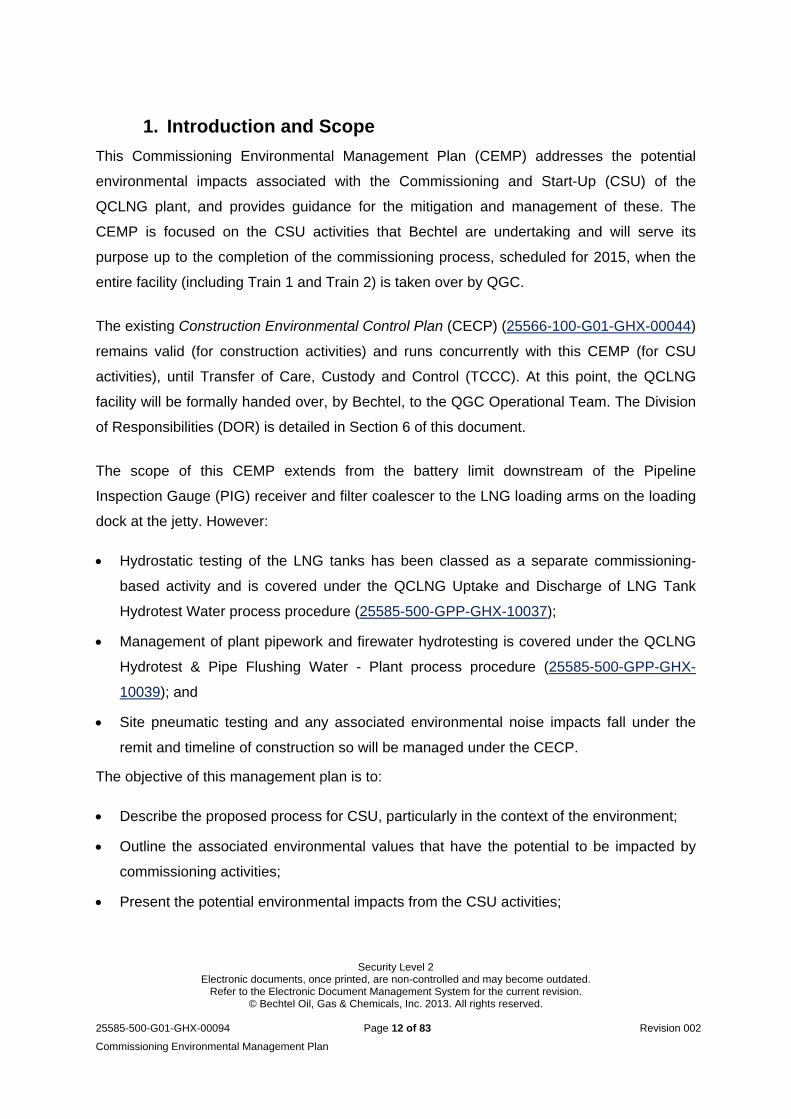
1. Introduction and Scope
This Commissioning Environmental Management Plan (CEMP) addresses the potential
environmental impacts associated with the Commissioning and Start-Up (CSU) of the
QCLNG plant, and provides guidance for the mitigation and management of these. The
CEMP is focused on the CSU activities that Bechtel are undertaking and will serve its
purpose up to the completion of the commissioning process, scheduled for 2015, when the
entire facility (including Train 1 and Train 2) is taken over by QGC.
The existing Construction Environmental Control Plan (CECP) (25566-100-G01-GHX-00044)
remains valid (for construction activities) and runs concurrently with this CEMP (for CSU
activities), until Transfer of Care, Custody and Control (TCCC). At this point, the QCLNG
facility will be formally handed over, by Bechtel, to the QGC Operational Team. The Division
of Responsibilities (DOR) is detailed in Section 6 of this document.
The scope of this CEMP extends from the battery limit downstream of the Pipeline
Inspection Gauge (PIG) receiver and filter coalescer to the LNG loading arms on the loading
dock at the jetty. However:
Hydrostatic testing of the LNG tanks has been classed as a separate commissioning-
based activity and is covered under the QCLNG Uptake and Discharge of LNG Tank
Hydrotest Water process procedure (25585-500-GPP-GHX-10037);
Management of plant pipework and firewater hydrotesting is covered under the QCLNG
Hydrotest & Pipe Flushing Water - Plant process procedure (25585-500-GPP-GHX-
10039); and
Site pneumatic testing and any associated environmental noise impacts fall under the
remit and timeline of construction so will be managed under the CECP.
The objective of this management plan is to:
Describe the proposed process for CSU, particularly in the context of the environment;
Outline the associated environmental values that have the potential to be impacted by
commissioning activities;
Present the potential environmental impacts from the CSU activities;
Security Level 2 Electronic documents, once printed, are non-controlled and may become outdated.
Refer to the Electronic Document Management System for the current revision. © Bechtel Oil, Gas & Chemicals, Inc. 2013. All rights reserved.
25585-500-G01-GHX-00094 Page 13 of 83 Revision 002
Commissioning Environmental Management Plan
Consider the environmental issues associated with the startup of Train 1 whilst Train 2 is
still in construction;
Identify relevant environmental objectives and performance criteria;
Present the relevant legislation, guidelines and other documents; and
Prescribe the environmental mitigation, management and monitoring that will be adopted
for the CSU process.
Note that this document serves as the overarching environmental management plan. As
required, additional internal procedures (such as activity specific procedures, Job Hazard
Analysis, Work Method Statements) will be developed as part of the ongoing assessment
and management of environmental risk. Ongoing management also features routine
environmental inspections and audits, recording incidents and training as discussed in
section 6 to 8.
For clarity, the stages discussed in this plan are defined as follows:
Mechanical completion – point when construction activities associated with the
installation of the facility (including, piping, instrumentation, electrical, and buildings) are
complete and in accordance to process specifications and drawings.
Pre-commissioning – includes the checking, cleaning and testing of the installed
permanent plant and equipment prior to CSU. Activities can include instrument
functional checks, cleaning of vessel and piping systems, nitrogen purging and leak
testing.
Commissioning – includes verification of functional operation through a structured
program of calibration, testing and certification to ensure all equipment is completed and
ready to introduce process / commissioning fluids. Also includes the verification that
support facilities can be started up and will operate within the design parameters and
specifications.
Start-up – once all commissioning test have identified the facility is fit to receive process
fluids and feed gas.
Operation – all necessary systems, resources and requirements to operate the facility
are operational and LNG is produced.
Security Level 2 Electronic documents, once printed, are non-controlled and may become outdated.
Refer to the Electronic Document Management System for the current revision. © Bechtel Oil, Gas & Chemicals, Inc. 2013. All rights reserved.
25585-500-G01-GHX-00094 Page 14 of 83 Revision 002
Commissioning Environmental Management Plan
1.1. Project Background
Queensland Gas Company (QGC), a wholly-owned subsidiary of British Gas Group PLC
(BG Group), is developing a world-scale, integrated liquefied natural gas project in
Queensland, known as the QCLNG project. The project will be one of Australia’s largest
capital projects and will supply a nominal 4.23million metric tonnes per annum (mtpa) of
LNG per Train.
The overall QCLNG project consists of the following components:
Coal seam gas (CSG) field development and supporting infrastructure in the Surat Basin
(Gas Field Component. Note: not part of Bechtel’s scope);
A network of underground pipelines, including gas and water collection pipelines in the
Gas Field Component, and 380 km of underground gas transmission pipeline (Export
Pipeline) from the Gas Field to an LNG Facility. (Pipeline Component. Note: not part of
Bechtel’s scope);
A gas liquefaction facility on Curtis Island, adjacent to Gladstone, initially comprising two
processing units, or “trains”. This component also includes an export jetty and other
supporting infrastructure (LNG Component. Note – within Bechtel’s scope);
Access channels for shipping vessels (Swing Basin and Channel. Note: not part of
Bechtel’s scope); and
LNG shipping operations to load the LNG and export it to global markets (Note: Shipping
Operations are not part of Bechtel’s scope).
For a full description of the project refer to the QCLNG draft Environmental Impact
Statements (EIS) and supplementary EIS (sEIS), which can be accessed at
www.qgc.com.au/environment/environmental-impact-management . The project component
relevant to this management plan is the gas liquefaction facility.
Security Level 2 Electronic documents, once printed, are non-controlled and may become outdated.
Refer to the Electronic Document Management System for the current revision. © Bechtel Oil, Gas & Chemicals, Inc. 2013. All rights reserved.
25585-500-G01-GHX-00094 Page 15 of 83 Revision 002
Commissioning Environmental Management Plan
1.2. Approvals, permits and legislation
1.2.1. Environmental Authority The QCLNG facility is defined as a petroleum facility under the Petroleum and Gas
(Production and Safety) Act 2004, and as such, required a petroleum facility license (PFL) in
order for its construction and operation. Under the guide of Chapter 5 in the Queensland
state Environmental Protection Act (EP Act) 1994, it is a legislative requirement for
petroleum activities to be issued with an Environmental Authority (EA). An application for a
PFL was lodged by QGC to DEHP, previously known as the Department of Environment and
Resource Management (DERM), and approval was granted under Environmental Authority
Permit Number: EPPG00711513.
Within this EA, there are conditions that are applicable to the CSU of the project and as
such, this is the key approval that any activities will be delivered within. The recent update is
effective 18 October 2013.
1.2.2. Other permits Other site specific permits and their respective conditions have been reviewed to identify
conditions which are relevant to CSU activities. The prescribed tidal works permit for the
LNG Jetty (DA 479/2011) and for Tidal Area Infrastructure (DA 239/2010) have been
identified as most applicable, and while they have not been discussed in detail within this
document, their requirements and responsibilities are not excluded from the overall delivery
of CSU. The majority of other permit conditions relate to construction activities and are
included within the project’s CECP, process procedures and/or activity based management
plans. Reference will be made to these during CSU as required.
1.2.3. Legislative Framework, Industry Standards and Guidelines There are many Local, State and Commonwealth legislative requirements, as well as
international agreements which are relevant to activities of project construction,
commissioning and operation. Some of these are presented in Appendix A. There are also
a number of industry standards, codes and guidelines relevant to the commissioning phase.
Bechtel Core Process 403: Legal and Other Requirements details Bechtel’s commitment to
adhere to all legal and non-legal responsibilities and obligations.
1.3. Related Documentation
This CEMP is supported by a suite of environmental planning and management instruments
that have been implemented during the project to manage environmental impacts, including:
Security Level 2 Electronic documents, once printed, are non-controlled and may become outdated.
Refer to the Electronic Document Management System for the current revision. © Bechtel Oil, Gas & Chemicals, Inc. 2013. All rights reserved.
25585-500-G01-GHX-00094 Page 16 of 83 Revision 002
Commissioning Environmental Management Plan
The QCLNG Environmental Impact Statement (EIS) and Supplementary information to
the EIS;
The QCLNG Environmental Services Manual;
Sub-management Plans (Attachments); and
The QCLNG Curtis Island Construction Environmental Control Plan.
As a Bechtel project, the commitments and obligations included in this CEMP and other
associated documents are supported by the Bechtel Core Processes and the Environmental
Services Manual.
1.4. Plan Structure
This CEMP is structured as follows:
Section 1 Introduction which includes the document objectives, project background and
relevant documentation.
Section 2 Description of LNG plant process which describes the relevant commissioning
activities and their location.
Section 3 Overall management approach which presents the performance criteria and
policy context.
Section 4 Environmental conditions and values.
Section 5 CSU activities, potential environmental impacts and associated management
Section 6 General environmental management including the project protocols for work
planning, incidents, and emergencies.
Section 7 Programmes and procedures.
Section 8 Environmental procedures and forms.
Security Level 2 Electronic documents, once printed, are non-controlled and may become outdated.
Refer to the Electronic Document Management System for the current revision. © Bechtel Oil, Gas & Chemicals, Inc. 2013. All rights reserved.
25585-500-G01-GHX-00094 Page 17 of 83 Revision 002
Commissioning Environmental Management Plan
2. Description of LNG Plant Process
This section outlines the LNG plant process to give context to the CSU activities and
potential environmental impacts that will be monitored and managed. For ease of
referencing, the process units have been numbered (Unit 11 to 39) which will allow clear
comparison with other related plans and documents.
2.1. LNG Plant Process
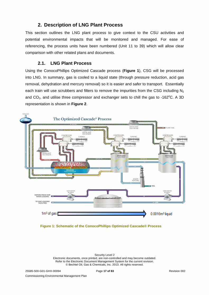
Using the ConocoPhillips Optimized Cascade process (Figure 1), CSG will be processed
into LNG. In summary, gas is cooled to a liquid state (through pressure reduction, acid gas
removal, dehydration and mercury removal) so it is easier and safer to transport. Essentially
each train will use scrubbers and filters to remove the impurities from the CSG including N2
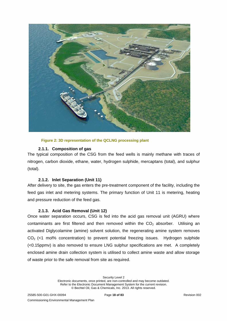
and CO2, and utilise three compressor and exchanger sets to chill the gas to -162oC. A 3D
representation is shown in Figure 2.
Figure 1: Schematic of the ConocoPhillips Optimized Cascade® Process
Security Level 2 Electronic documents, once printed, are non-controlled and may become outdated.
Refer to the Electronic Document Management System for the current revision. © Bechtel Oil, Gas & Chemicals, Inc. 2013. All rights reserved.
25585-500-G01-GHX-00094 Page 18 of 83 Revision 002
Commissioning Environmental Management Plan
Figure 2: 3D representation of the QCLNG processing plant
2.1.1. Composition of gas The typical composition of the CSG from the feed wells is mainly methane with traces of
nitrogen, carbon dioxide, ethane, water, hydrogen sulphide, mercaptans (total), and sulphur
(total).
2.1.2. Inlet Separation (Unit 11) After delivery to site, the gas enters the pre-treatment component of the facility, including the
feed gas inlet and metering systems. The primary function of Unit 11 is metering, heating
and pressure reduction of the feed gas.
2.1.3. Acid Gas Removal (Unit 12) Once water separation occurs, CSG is fed into the acid gas removal unit (AGRU) where
contaminants are first filtered and then removed within the CO2 absorber. Utilising an
activated Diglycolamine (amine) solvent solution, the regenerating amine system removes
CO2 (<1 mol% concentration) to prevent potential freezing issues. Hydrogen sulphide
(<0.15ppmv) is also removed to ensure LNG sulphur specifications are met. A completely
enclosed amine drain collection system is utilised to collect amine waste and allow storage
of waste prior to the safe removal from site as required.
Security Level 2 Electronic documents, once printed, are non-controlled and may become outdated.
Refer to the Electronic Document Management System for the current revision. © Bechtel Oil, Gas & Chemicals, Inc. 2013. All rights reserved.
25585-500-G01-GHX-00094 Page 19 of 83 Revision 002
Commissioning Environmental Management Plan
2.1.4. Dehydration (Unit 13) The treated gas leaving the AGRU is chilled prior to entering the dryer inlet separator for
separation of CO2, H2O and trace hydrocarbons. Dehydration is facilitated within the
molecular sieve dehydrators, where the final traces of H2O vapour are removed (<1ppm) to
prohibit ice particles forming in the gas stream while it passes through downstream units.
2.1.5. Mercury Removal (Unit 13) This final gas treatment step removes any trace amounts of mercury (Hg+), preventing
potential corrosion damage to downstream heat exchangers. To aid Hg+ absorption, gas is
passed through sulphur-impregnated activated carbon beds. Further filtration of gas particles
is conducted before entering the refrigeration and liquefaction units. As the activated carbon
beds have a design life of 3 years (mercury-content dependant) these will only need to be
removed and managed as a regulated waste stream (if there is mercury present) later in the
plant operational phase. Defrost gas will be provided from the dry feed gas downstream of
Unit 13 or other suitable sources (e.g. methane system), and will regenerated to the
liquefaction plant.
2.1.6. Liquefaction (Units 14, 15 & 16) Through a combined process of heat exchange and pressure reduction with refrigerants, dry
gas is liquefied into LNG. This system of cascade and compression consists of three (3)
refrigeration services, namely propane (C3H8), ethylene (C2H4) and methane. Each unit is
driven by two independent General Electric LM2500+ G4 gas turbine refrigerant
compressors and equipped with individual suction drums and anti-surge controls. There is
also a Waste Heat Recovery (WHR) system affixed to the CH4 compressor unit for the
recovery of gas turbine exhaust heat.
After the gas passes through dry gas filters, it is partially cooled in the C3H8 refrigeration
system, with the heat removed to the atmosphere from numerous extraction fans. The cool
gas then enters the C2H4 refrigeration system for further cooling and condensed by heat
exchangers in the C2H4 cold box. Lastly, the gas enters the CH4 refrigeration system for final
cooling to ≈ 160oC and N2 removal through the cryogenic nitrogen rejection unit (NRU) and
cold box.
2.1.7. LNG Storage (Unit 24) Two large cryogenic LNG storage tanks, each with a capacity of 140,000m3, will store the
LNG produced by Train 1 and Train 2. Each tank, built with double-wall concrete structure
with the internal walls having sheets of 9% nickel alloy welded together. Each LNG storage
Security Level 2 Electronic documents, once printed, are non-controlled and may become outdated.
Refer to the Electronic Document Management System for the current revision. © Bechtel Oil, Gas & Chemicals, Inc. 2013. All rights reserved.
25585-500-G01-GHX-00094 Page 20 of 83 Revision 002
Commissioning Environmental Management Plan
tank will be equipped with loading pumps, level gauges, level transmitters, relief valves,
vents, temperature elements, and other basic instrumentation necessary for the appropriate
monitoring and management of the facility components.
To ensure complete enclosure of the LNG tanks, each tank will undergo hydrotesting to
approximately 60% of the total volume with 88.3 mega litres (ML) of water. The procedure
for hydrotesting is outlined in the Uptake and Discharge of LNG Tank Hydrotest Water
process procedure (25585-500-GPP-GHX-10037).
2.1.8. LNG Jetty and ship loading From the LNG storage tanks, the product will be pumped to the jetty along a network of
piping, where it is then transferred to the LNG ship via several loading arms. The LNG jetty
is designed for the berthing, mooring, and handling of LNG carriers of up to 220,000m3
capacity, and includes:
A loading platform with four 16” LNG loading arms (2 liquid, 1 vapor, and 1 hybrid) to
achieve minimum 12,000 m3/hr;
Four breasting dolphins, six mooring dolphins and interconnecting catwalks;
An access trestle with roadway and pipe-way to the shore; and
Marine terminal building platform.
As a safety precaution, the vapour return arm will capture any displaced gas from the ship
tanks and any flashed / vaporised gas from the ship loading, and return it to the LNG tanks.
This gas will undergo further compression within the boil off gas (BOG) system and the
Wet/Dry Gas Flare K.O Drum, where it will be returned to the liquefaction system for
processing. During CSU and initial operational activities, it is anticipated that excess gas
during ship loading may be produced and will need to follow the path to the BOG and re-
liquefaction systems. However, given the variations in the initial CSU and operational
activities, there may be a need to discharge the surplus gas via the flare and relief system.
2.1.9. Utilities Ancillary utilities necessary for the CSU phase, and furthermore the operations, of the facility
are detailed below.
2.1.9.1. Flare and Relief System (Unit 19) A system of three (3) separate flare systems will be implemented to cater for the release of
H2O vapour and gas releases associated with the production processes. The flare system
features a co-located Wet and Dry Gas Flare stack and a Marine Flare stack. These flare
Security Level 2 Electronic documents, once printed, are non-controlled and may become outdated.
Refer to the Electronic Document Management System for the current revision. © Bechtel Oil, Gas & Chemicals, Inc. 2013. All rights reserved.
25585-500-G01-GHX-00094 Page 21 of 83 Revision 002
Commissioning Environmental Management Plan
systems are a primary safety feature of the LNG facility collecting and disposing of
hydrocarbon-contaminated streams typically released during start-up, shutdown and
emergency conditions. Increased flaring is a normal and expected part of the commissioning
and start-up of the plant and is required to get a better operational environmental outcome.
The Wet Gas Flare will release any waste hydrocarbon streams possibly saturated with H2O
vapour and/or free liquid hydrocarbons. The Dry Gas Flare system will provide a system of
release of cryogenic hydrocarbons (vapour or liquid) from the process trains.
The Marine Flare will dispose of any flashed LNG vapours generated from the LNG storage
tanks and the BOG system, as well as during the loading of the LNG transport ships. BOG
compression is significant in limiting the amount of flare required during plant operation and
the LNG loading process.
2.1.9.2. Diesel Storage and Transfer Diesel, for site wide usage, will be bunkered to the facility as per the Diesel Delivery
Execution Plan (25585-500-G01-GCX-10002) and will be stored in the Fuel Farm. Diesel will
be transferred, via underground piping from the fuel farm, to the Diesel Oil Transfer Pump
and onward to the associated day tanks servicing the Stand-by Diesel Generators, the
Firewater Pumps and the Start-up/Stand-by Air Compressors.
2.1.9.3. Power Generation A standby generator system, consisting of three (3) Construction Power Diesel Generator
Black Start packages and one (1) Standby Diesel Generator Marine Terminal Building
Package, will supply power during system outages. The Construction Power Diesel
Generators are designed with bi-fuel conversion (diesel and LP gas fuel), with the rated
capacity of 1600kW each. However during commissioning these will initially be powered by
diesel until fuel gas becomes available.
When operational, the facility will be self-sufficient, utilising 100% CSG to facilitate power
generation (of up to 50 megawatt – 28MW for Train 1 and 20MW for Train 2/3) for the plant
and associated infrastructure. Additionally, backup generators will be implemented within
the facility to cater for periods of minimum turndown or complete shutdown. Each of these
generators are equipped with low NOx emission systems.
2.1.9.4. Plant and Instrument Air (Unit 35) and Nitrogen (Unit 39) Two 50% motor-driven air compressors will supply utility air, instrument air, and feed air to
the Nitrogen Generation Package. The diesel star-up/back-up Air Compressor Packages will
Security Level 2 Electronic documents, once printed, are non-controlled and may become outdated.
Refer to the Electronic Document Management System for the current revision. © Bechtel Oil, Gas & Chemicals, Inc. 2013. All rights reserved.
25585-500-G01-GHX-00094 Page 22 of 83 Revision 002
Commissioning Environmental Management Plan
supply all necessary air required for initial commissioning activities. N2 will be used as
“blanket” gas for selected storage tanks and as a purge gas during pre-commissioning and
commissioning stages. N2 gas will be supplied to the facility by nitrogen generation units. A
liquid nitrogen back-up system will also be provided.
2.1.9.5. Firewater Systems (Units 33) The QCLNG Facility will be equipped with a self-sufficient fire protection system, supplied by
the utility water system and stored in two (2) firewater tanks. This firewater system is
common for both Train 1 and Train 2 facilities, as well as the LNG Jetty. The use of passive
protection within the processing plant equipment and the reserved fire-water system will
minimise the release of liquid spillages to surface water or land. The fire protection and
safety systems include:
fire water – underground distribution loop and above-ground system;
fire and gas detection systems – response to release of combustible, hazardous and/or
low temperature gases and fires;
fire proofing – all major structural steel and insulated vessels in the liquefaction section
that normally contain flammable or combustible hydrocarbon;
fire water tank; and
fire water pumps – diesel driven.
2.1.9.6. Fuel Gas A fuel gas system will provide usable fuel gas (under high pressure and low pressure) and
will engage initial start-up (black start) to generator turbine drivers1, six (6) refrigerant
compressor turbine drivers2, fire heaters2, flares, as well as tank and vessel blanketing. Fuel
gas will be implemented during the commissioning process and will continue to be in use
throughout the lifetime of the facility. Once the hot oil system is started up, fuel gas supply is
changed from the black start fuel gas to the start-up fuel gas slipstream downstream of the
feed gas heater.
2.1.9.7. Hot Oil System (Unit 34) A closed loop, hot oil system will provide the process heating requirements for the facility.
Waste heat generated from the CH4 compressor gas turbine exhausts will be recovered via
1 Use of high pressure gas 2 Use of low pressure gas
Security Level 2 Electronic documents, once printed, are non-controlled and may become outdated.
Refer to the Electronic Document Management System for the current revision. © Bechtel Oil, Gas & Chemicals, Inc. 2013. All rights reserved.
25585-500-G01-GHX-00094 Page 23 of 83 Revision 002
Commissioning Environmental Management Plan
the Waste Heat Recovery Units to circulate heat through the oil. Exhaust from the C3H8 and
C2H4 compressor gas turbine is not recovered. A gas fired hot oil heater will be implemented
to cover both LNG trains as a backup during minimum turndown periods but will also feature
during start-up.
2.1.9.8. Refrigerant Storage Refrigerant storage will be provided for both the C2H4 and C3H8 systems, allowing for
periodic replenishment of each refrigerant circuit, as well as storage during maintenance.
These systems will be common to both Train 1 and Train 2.
2.2. Associated Infrastructure
2.2.1. Water Supply, Management and Storage
2.2.1.1. Potable Water Potable water is currently supplied to the project (including the TCF) through the GAWB
pipeline. All potable water supplied to the site, including that supplied to the TCF and all
permanent and construction offices, is currently monitored in accordance to the AS/NZS
5667.1:1998 Water quality – Sampling (as per the Potable Water Monitoring Process
Procedure (25566-500-GPP-GHX-10014) for compliance with the Australian Drinking Water
Guidelines (ADWG) and the relevant Australian Standards. During construction, the primary
activities which demand the use of potable water are concrete batching and pipe hydrostatic
testing. During CSU and operational activities (up to TCCC), the main demand for potable
(or demineralised) water use is for amine makeup and pipe flushing as discussed below.
2.2.1.2. Water treatment system (Unit 36) The water treatment system has been designed to treat water from GAWB to generate
demineralised water, service water and fire water. The unit will utilise a sodium hypochlorite
injection package, an ultrafiltration package, brackish water reverse osmosis (BWRO)
package, and an electro-deionisation (EDI) package. It will produce the demineralised water
required for the amine storage tank, demineralised make-up and facility wash water.
2.2.1.3. Stormwater Management (non-process areas) Throughout construction, a stormwater drainage system has been used to direct all runoff to
either the diversion drains (east and west) or sediment basins. Full details of the site
management of surface water can be reviewed in the CECP, Attachment 8 – Stormwater
Quality Management Plan (25585-500-GOI-GHX-00089).
Security Level 2 Electronic documents, once printed, are non-controlled and may become outdated.
Refer to the Electronic Document Management System for the current revision. © Bechtel Oil, Gas & Chemicals, Inc. 2013. All rights reserved.
25585-500-G01-GHX-00094 Page 24 of 83 Revision 002
Commissioning Environmental Management Plan
During CSU, any uncontaminated stormwater will be diverted to the sediment basins to
manage discharge to Port Curtis. Should the rainfall event exceed the respective basin
design capacity, the gravitational discharge of stormwater will be through the rock-lined
spillway to the marine environment.
The final design of the sediment basin is for the installation of low-flow pipes to ensure the
constant drainage of the basin. However, the current infrastructure allows for turbid
stormwater to be retained, treated and later mechanically discharged. Further information
regarding the management of storm water runoff during CSU and initial operational activities
(up to TCCC) is detailed in Section 5.3 of this document.
2.2.2. Waste water and effluent management The project will produce waste water and effluent during CSU. This will include sewage
effluent, waste process water (from Unit 36 discussed in section 2.2.1.2) and stormwater
from process areas (treated via Unit 29). Each source will be treated and disposed
separately. Sewage effluent will continue to be transferred from the sewage collection tanks
and transported to the sanitary lift station located in Area 11. Additionally, sewage produced
from operational buildings will flow underground to sumps before being pumped to the
sanitary lift station. The sewage will continue to be transported directly to the GAWB pipeline
located at the northern border of site. Stormwater from the process areas will be treated
through the onsite wastewater treatment system (Unit 29) and discharged through the
Seawater Outfall, located on the jetty. Waste process water effluent (from Unit 36) will also
be discharged to the Seawater Outfall. The clean condensate generated from the Inlet air
chilling (IAC) unit which is released to the atmosphere from the gas turbine inlet coils will be
routed to the stormwater system. Further information regarding the onsite waste water and
effluent management has been detailed in Section 5.3.2 of this document.
2.2.3. Amine and Hot Oil Drainage Areas that may contain amine (e.g. amine process area, wastewater tank, or wet flare
knock-out drum pumps) are bunded for containment, draining to dedicated underground
collection headers and ultimately the amine sump drum. This amine will be collected and
can be recycled back in to the process. In the event of an incident during CSU, the
immediate removal of material from these containment areas will be through the use of
wastewater trucks, which can either remove the waste off-site for disposal / treatment, or
transferred to the wastewater tank.
Security Level 2 Electronic documents, once printed, are non-controlled and may become outdated.
Refer to the Electronic Document Management System for the current revision. © Bechtel Oil, Gas & Chemicals, Inc. 2013. All rights reserved.
25585-500-G01-GHX-00094 Page 25 of 83 Revision 002
Commissioning Environmental Management Plan
The hot oil system does not discharge to the wastewater sump. If equipment containing hot
oil requires draining, it will either be returned to the hot oil storage tank via pipe (using
nitrogen) or a temporary storage tank.
2.3. Other CSU activity
In addition to the process based commissioning activities and associated environmental
releases, there will be other activity that has the potential to impact the environment if
appropriate mitigation and management is not implemented. This includes materials storage
and handling, waste management and dangerous goods/hazardous substances. Details of
these are presented below with corresponding management and monitoring (where
required).
2.3.1. Lube oil flushing Lube oil system flushing will be performed by circulating mineral or synthetic oil through each
piece of equipment, using external filters, heaters, pumps and moisture removal equipment.
The purpose of the oil flushing is to remove all impurities from the oil circuits and prevent
impurities from entering critical devices, such as machine bearings, during normal operation.
2.3.2. Chemical cleaning Some pipework and equipment will require chemically cleaning which involves the circulation
of chemicals (diluted in a solution). The transportation, storage, usage and removal of the
chemicals will be undertaken in line with the site’s management of dangerous goods and
hazardous substances as outlined in Section 5.4. The chemical effluent created from the
process will either be discharged as trade waste (subject to approval) or regulated waste.
2.3.3. Degreasing of the Acid Gas Removal Unit Degreasing of the Acid Gas Removal Unit will be done by circulating clean demineralised
water at ambient temperature throughout the liquid system to remove the bulk of dirt, loose
scale, slag and debris. The system will then be flushed with a three (3) percent Potash
Solution. This procedure is necessary to remove oil, grease, remaining debris and scale
from piping and equipment. Removal of these contaminants greatly reduces possibilities of
equipment fouling and amine solution foaming. After flushing with Potash solution, the
system will be rinsed with demineralised water.
2.3.4. Materials Storage and Handling All materials required for the commissioning phase of the LNG facility will be stored, handled
and disposed of in accordance with relevant legislation, Australian Standards (AS) and the
project’s EA. Refer to CECP Attachment 17 – Waste Management Plan (25566-100-G01-
Security Level 2 Electronic documents, once printed, are non-controlled and may become outdated.
Refer to the Electronic Document Management System for the current revision. © Bechtel Oil, Gas & Chemicals, Inc. 2013. All rights reserved.
25585-500-G01-GHX-00094 Page 26 of 83 Revision 002
Commissioning Environmental Management Plan
GHX-00059) and Attachment 24 – Dangerous Goods and Hazardous Substances
Management Plan (25566-100-G01-GHX-00066).
2.3.5. Waste Management Efficient use of available resources and effective waste management are an integral
component of the commissioning phase. This includes minimising the potential effects of
odour, short-term pollution and any long-term contamination of soils, air or water.
The identification, handling, segregation and disposal of waste generated from
commissioning activities shall be consistent, and in accordance, with the CECP Attachment
17 - Waste Management Plan (25566-100-G01-GHX-00059). This procedure considers best
practice environmental management (BPEM) and includes the state legislative requirements
of Environmental Protection (Waste Management) Policy (EPP Waste) 2000 and the
Environmental Protection (Waste Management) Regulation 2000. For the CSU activities,
the generation of any additional waste streams (classified as trackable (regulated) and
general wastes) will be controlled in line with this CEMP, permit conditions and the above
legislative requirements.
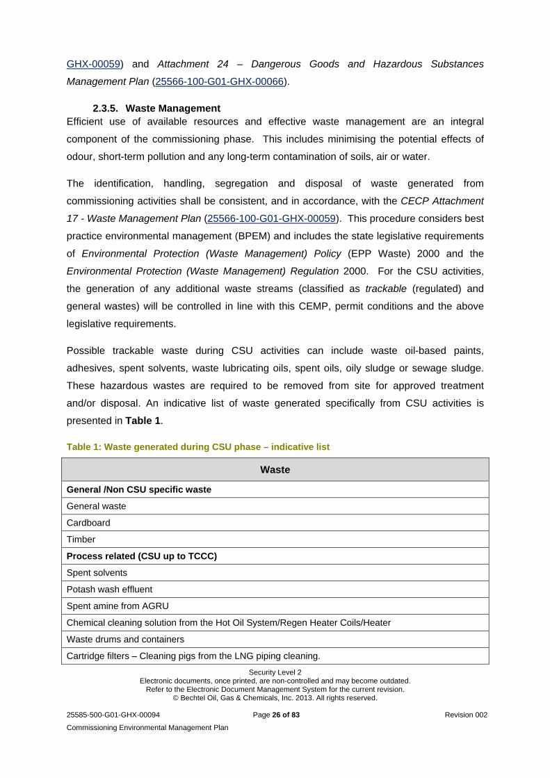
Possible trackable waste during CSU activities can include waste oil-based paints,
adhesives, spent solvents, waste lubricating oils, spent oils, oily sludge or sewage sludge.
These hazardous wastes are required to be removed from site for approved treatment
and/or disposal. An indicative list of waste generated specifically from CSU activities is
presented in Table 1.
Table 1: Waste generated during CSU phase – indicative list
Waste
General /Non CSU specific waste
General waste
Cardboard
Timber
Process related (CSU up to TCCC)
Spent solvents
Potash wash effluent
Spent amine from AGRU
Chemical cleaning solution from the Hot Oil System/Regen Heater Coils/Heater
Waste drums and containers
Cartridge filters – Cleaning pigs from the LNG piping cleaning.
Security Level 2 Electronic documents, once printed, are non-controlled and may become outdated.
Refer to the Electronic Document Management System for the current revision. © Bechtel Oil, Gas & Chemicals, Inc. 2013. All rights reserved.
25585-500-G01-GHX-00094 Page 27 of 83 Revision 002
Commissioning Environmental Management Plan
Waste
Utility related (CSU up to TCCC)
Inorganic sludge from demineralisation unit
Oily sludge from CPI oil separator
Maintenance related
Spent lubricating oil
Used batteries
Oily filters / rags
Grease
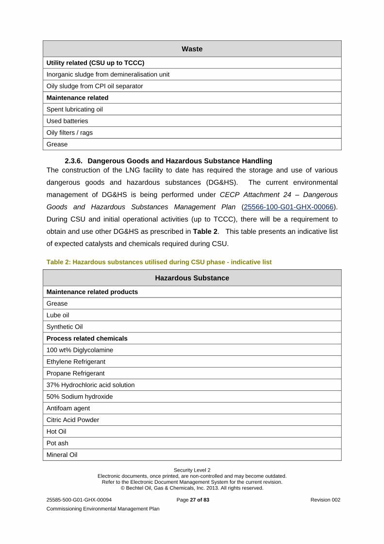
2.3.6. Dangerous Goods and Hazardous Substance Handling The construction of the LNG facility to date has required the storage and use of various
dangerous goods and hazardous substances (DG&HS). The current environmental
management of DG&HS is being performed under CECP Attachment 24 – Dangerous
Goods and Hazardous Substances Management Plan (25566-100-G01-GHX-00066).
During CSU and initial operational activities (up to TCCC), there will be a requirement to
obtain and use other DG&HS as prescribed in Table 2. This table presents an indicative list
of expected catalysts and chemicals required during CSU.
Table 2: Hazardous substances utilised during CSU phase - indicative list
Hazardous Substance
Maintenance related products
Grease
Lube oil
Synthetic Oil
Process related chemicals
100 wt% Diglycolamine
Ethylene Refrigerant
Propane Refrigerant
37% Hydrochloric acid solution
50% Sodium hydroxide
Antifoam agent
Citric Acid Powder
Hot Oil
Pot ash
Mineral Oil

Security Level 2 Electronic documents, once printed, are non-controlled and may become outdated.
Refer to the Electronic Document Management System for the current revision. © Bechtel Oil, Gas & Chemicals, Inc. 2013. All rights reserved.
25585-500-G01-GHX-00094 Page 28 of 83 Revision 002
Commissioning Environmental Management Plan
Hazardous Substance
Na-dodecylbenzene sulphonate powder
Na-EDA Powder
Soda ash
Sodium bisulphate
Sodium hydrosulphite powder
Sodium hydroxide (50% liquid)
Sodium hyperchlorite (10%)
Sodium tripolyphosphate (100%)
Sulphuric acid
Utility related chemicals
Diesel
Unleaded Fuel
Hydraulic oil
2.4. Construction Phase Activities during Commissioning
The QCLNG project requires the construction, commissioning and operation of 2 LNG trains
which will mean there is simultaneous operation (SimOp) within/nearby the same area. A
SimOps Risk Screening Workshop was held on-site between QGC and Bechtel on 12–13th
December 2012, with the key objective of identifying high-level risks caused by:
1. CSU activities occurring simultaneously with construction activities; or
2. Operational activities by QGC while construction or commissioning activities are
underway by Bechtel.
Once the risks were identified, mitigation measures were identified to reduce the risks to an
acceptable or as low as reasonably practicable (ALARP) level.
With relevance to Bechtel’s CSU activities and this CEMP, one key environmental SimOps is
the construction of Train 2 during the commissioning or operations of Train 1. Throughout
the CSU phase, construction activities will continue to be performed within Train 2 and
surrounding areas. All construction activities will continue to be undertaken in accordance
with the CECP, Australian legislation, standards and guidelines. As an example, airborne
dust particles will continue to be suppressed through routine operation of water carts
(utilising a polymer dust-suppressant solution). This service will concentrate on the
trafficable areas surrounding the CSU and process areas, in order to reduce the potential of

Security Level 2 Electronic documents, once printed, are non-controlled and may become outdated.
Refer to the Electronic Document Management System for the current revision. © Bechtel Oil, Gas & Chemicals, Inc. 2013. All rights reserved.
25585-500-G01-GHX-00094 Page 29 of 83 Revision 002
Commissioning Environmental Management Plan
delays or interruptions. Further information regarding construction processes is detailed in
the Construction Execution Plan (25585-500-GOI-GCX-00001).
Security Level 2 Electronic documents, once printed, are non-controlled and may become outdated.
Refer to the Electronic Document Management System for the current revision. © Bechtel Oil, Gas & Chemicals, Inc. 2013. All rights reserved.
25585-500-G01-GHX-00094 Page 30 of 83 Revision 002
Commissioning Environmental Management Plan
3. Overall Environmental Management Approach
Without considering best practice environmental practices and preventative control
measures, CSU activities have the potential to impact the local environment and surrounding
sensitive receptors. There is therefore a requirement to provide a consistent management
approach towards reducing and/or eliminating these impacts during the commissioning of
the project. This section of the CEMP outlines the overarching environmental management
strategy for CSU on the project. Specific management and monitoring measures are
discussed in Section 5.
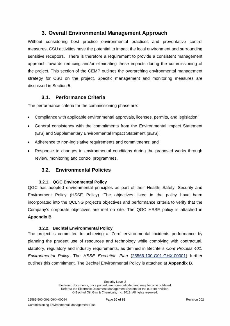
3.1. Performance Criteria
The performance criteria for the commissioning phase are:
Compliance with applicable environmental approvals, licenses, permits, and legislation;
General consistency with the commitments from the Environmental Impact Statement
(EIS) and Supplementary Environmental Impact Statement (sEIS);
Adherence to non-legislative requirements and commitments; and
Response to changes in environmental conditions during the proposed works through
review, monitoring and control programmes.
3.2. Environmental Policies
3.2.1. QGC Environmental Policy QGC has adopted environmental principles as part of their Health, Safety, Security and
Environment Policy (HSSE Policy). The objectives listed in the policy have been
incorporated into the QCLNG project’s objectives and performance criteria to verify that the
Company’s corporate objectives are met on site. The QGC HSSE policy is attached in
Appendix B.
3.2.2. Bechtel Environmental Policy The project is committed to achieving a ‘Zero’ environmental incidents performance by
planning the prudent use of resources and technology while complying with contractual,
statutory, regulatory and industry requirements, as defined in Bechtel’s Core Process 401:
Environmental Policy. The HSSE Execution Plan (25566-100-G01-GHX-00001) further
outlines this commitment. The Bechtel Environmental Policy is attached at Appendix B.
Security Level 2 Electronic documents, once printed, are non-controlled and may become outdated.
Refer to the Electronic Document Management System for the current revision. © Bechtel Oil, Gas & Chemicals, Inc. 2013. All rights reserved.
25585-500-G01-GHX-00094 Page 31 of 83 Revision 002
Commissioning Environmental Management Plan
4. Environmental conditions and values
Due to the nature and location of the project, there are a variety of environmental conditions
and values that are relevant to the commissioning phase of the QCLNG project. Project
relevant environmental aspects have been detailed in the CECP and the associated aspect
specific procedures. There is also a general description of the environmental values in the
EIS and sEIS. This section presents a summary of the environmental values and
commitments identified for the CSU phase of the QCLNG facility.
4.1. Climatic Conditions
The Gladstone region has a sub-tropic climate; averaging 267 days of sunshine annually, an
average temperature range of 27.2°C (maximum) and 12.7°C (minimum) and a mean rainfall
of approximately 750mm. The heaviest rainfall generally occurs during summer (December
to February) in line with the northern tropical monsoonal season. With strong influences
from sea breezes, the region experiences diurnal seasons, with variation in air temperature
greatest in winter (June to August).
The site operates a weather station to monitor the localised weather. This information will be
available for use in the context of how it may influence potential air quality (and noise)
impacts from CSU. In relation to dispersion meteorology, the project EIS identified:
The site is dominated by moderate wind speeds (65% of wind at 2-5 m/s), which
provides for relatively good dispersion conditions for stack sources;
The prevailing wind direction are easterlies and south-easterlies; and
Drainage flows are westerlies.
4.2. Sensitive receptors (noise, vibration and air quality)
The LNG Facility is situated approximately 4km from the nearest single residence on islands
in Port Curtis, 7.5km from major residential areas in Gladstone City and 9km from the
community at South End on Curtis Island. As discussed in section 2, the TCF is also located
within the project site and is, as such, a sensitive receptor from a noise and air quality
perspective.
The nearest industries to the proposed LNG Facility are Cement Australia and Queensland
Energy Resources, on either side of Landing Road at Fisherman’s Landing (adjacent to the
wharf facilities). Other industries within the local area include Rio Tinto Aluminum (7km to

Security Level 2 Electronic documents, once printed, are non-controlled and may become outdated.
Refer to the Electronic Document Management System for the current revision. © Bechtel Oil, Gas & Chemicals, Inc. 2013. All rights reserved.
25585-500-G01-GHX-00094 Page 32 of 83 Revision 002
Commissioning Environmental Management Plan
the south-west), Orica (7.3km to the south-southwest) and the NRG Gladstone Power
Station (9.3km to the south-southeast). Environmental values to be protected from changes
in noise, vibration and air quality include:
The health and biodiversity of ecosystems;
Human health and wellbeing within a suitable acoustic environment; and
The amenity of the community.
In relation to marine noise, the environmental objective is to ensure that no significant
behavioral disturbance occurs which may impact the long-term survival chances of the
individual or species. Appendix 5.14 of the EIS surveyed typical noise emissions from
construction activities against these receptors, with the results of computer modeling
(presented as noise contour maps) shown in Figure 3. The red contours represent noise
levels between 54 and 45 dBA (approximately). Orange contours represent noise levels from
42 to 39 dBA (approximately). Yellow contours represent noise levels between 36 and 33
dBA and green between 30 and 15 dBA. This gives an indication of the potential extent of
noise at the prescribed levels.
Figure 3: Noise emissions from construction activities under typical weather
Security Level 2 Electronic documents, once printed, are non-controlled and may become outdated.
Refer to the Electronic Document Management System for the current revision. © Bechtel Oil, Gas & Chemicals, Inc. 2013. All rights reserved.
25585-500-G01-GHX-00094 Page 33 of 83 Revision 002
Commissioning Environmental Management Plan
No on-site quantitative noise monitoring has been requested by the regulatory agencies (as
a result of a compliant) to date and dust has been monitored in the qualitative fashion over
the duration of construction. The management of noise and air quality for CSU is discussed
in section 5.
4.3. Visual (Lighting)
A landscape and visual impact assessment was undertaken as part of the project EIS. The
predominant sensitive visual receptor is the Great Barrier Reef World Heritage Area
(GBRWHA) and The Narrows (listed on the Australian Heritage Commission Register of
National Estate). The EIS denotes that ‘there will be no additional visual impact during Stage
5 (Commissioning of the LNG Facility) beyond that assessed in the previous stages’ i.e.
construction. The site is also visible from a number of publicly accessible viewpoints as
detailed in the EIS. Lighting is discussed in more detail in section 5.
4.4. Ecology
The site is located in relatively close proximity to sensitive terrestrial and aquatic ecological
receptors. This includes un-vegetated mud and sand banks, mangroves, saltmarsh and
seagrass meadows. These vegetated areas contribute to the complexity and biodiversity of
an estuarine environment for various marine flora and fauna communities, including benthic
invertebrates.
These habitats also provide a feeding habitat for waders listed as migratory under the EPBC
Act and protected under international migratory bird agreements (i.e. JAMBA and/or CAMBA
and/or ROKAMBA.) (Note: The intertidal area adjacent to the plant has been established as
not being significant for roosting or foraging. There are more suitable sites on Curtis Island).
Figure 4 shows the location of the salt pans (yellow) and the mangroves (green).

Security Level 2 Electronic documents, once printed, are non-controlled and may become outdated.
Refer to the Electronic Document Management System for the current revision. © Bechtel Oil, Gas & Chemicals, Inc. 2013. All rights reserved.
25585-500-G01-GHX-00094 Page 34 of 83 Revision 002
Commissioning Environmental Management Plan
Figure 4: Location of saltpans and mangrove areas in conjunction with facilities
Other ecological values in the area include but are not limited to:
The GBRWHA extends seaward from the low water mark on the Queensland coast,
covering the waters and islands within the Port of Gladstone including Curtis Island.
This area is also classed as a Matter of National Environmental Significance under
the commonwealth Environmental Protection & Biodiversity Conservation (EPBC) Act
1999, and is listed on the register of National Heritage Places.
The southern boundary of the Queensland State Great Barrier Reef Coast Marine
Park (GBRCMP) crosses The Narrows between Friend Point on the mainland and
Laird Point on Curtis Island.
The Curtis Island National Park, which extends north of Graham Creek, on the east
side of Curtis Island.
The Curtis Island State Forest, which is located approximately 10km north-west of
the facility on the northern side of Graham Creek.
These values along with those noted below are important in the context of CSU given the
interface with the marine environment (i.e. the LNG Jetty seawater outfall). Details of how
Security Level 2 Electronic documents, once printed, are non-controlled and may become outdated.
Refer to the Electronic Document Management System for the current revision. © Bechtel Oil, Gas & Chemicals, Inc. 2013. All rights reserved.
25585-500-G01-GHX-00094 Page 35 of 83 Revision 002
Commissioning Environmental Management Plan
water and wastewater will be managed on site are presented in section 5. Further details of
the ecological value of the surrounding area are contained within the EIS and sEIS.
4.5. Groundwater
The QCLNG EIS identified two groundwater bores on Curtis Island. Aquifer details provided
from the Groundwater Database maintained by the DERM (now DEHP), indicated relatively
poor groundwater quality. Initial site monitoring indicated groundwater depths of 2.3m to
2.5m, and that these levels are expected to change to an elevation of 1.0/2.0 AHD, with the
rise primarily following extended wet weather periods.
Since undertaking bulk earthworks, groundwater monitoring bores (currently eight) were
installed in the Holecene sediments of the site’s coastal perimeter and have been monitored
monthly for groundwater levels and groundwater quality (pH, Electrical Conductivity
Titratiable Acidity, Chloride, Sulphate, and filtered Iron and Aluminum). When compared to
historical baseline data, this monitoring has shown that test results have remained within
acceptable project limits and that groundwater levels have risen as expected.
4.6. Surface Water
As discussed in section 2.2.1.3, the natural surface water drainage on site has been
reconfigured in to a stormwater drainage system which features a number of internal drains,
sediment basins (referenced as 1 to 7) and two clean water diversion drains (east and west).
This stormwater system drains to the marine environment through designated discharge
points. Surface water quality monitoring has been undertaken on site throughout
construction.
4.7. Marine water
In addition to the publicly available information, the project has been collecting background
seawater quality data since December 2012 from the Construction Dock (CD) (close to the
LNG Jetty intake/diffuser area) and the Material Offloading Facility (MOF). Details of the
results are documented within the QCLNG Uptake and Discharge of LNG Tank Hydrotest
Water process procedure (25585-500-GPP-GHX-10037). The in-situ and laboratory results
have also been compared to relevant guidelines i.e. Guidelines for Fresh and Marine Water
Quality, Australia and New Zealand Environment Conservation Council (ANZECC). This
information will be useful in understanding and managing any potential impacts that CSU
activities may have on the marine environment.
Security Level 2 Electronic documents, once printed, are non-controlled and may become outdated.
Refer to the Electronic Document Management System for the current revision. © Bechtel Oil, Gas & Chemicals, Inc. 2013. All rights reserved.
25585-500-G01-GHX-00094 Page 36 of 83 Revision 002
Commissioning Environmental Management Plan
5. CSU activities, potential environmental impacts and
associated management
This section presents the activity specific potential environmental impacts associated with
the CSU of the QCLNG plant. The Process Environmental Flow Diagram for emissions
(Figure 5) and for wastewater/effluent (Figure 6) highlights the plant processes with their
associated outputs. The section is broken in to individual aspects (air, noise, water etc)
noting the relevant CSU activities and the potential environmental impacts (air emissions,
solid waste, and water / effluent streams). Relevant activities are then discussed in detail
along with specific management strategies.
An internal risk assessment (including a workshop) was undertaken, which was documented
in an environmental risk register. The risk process was undertaken in accordance with
Bechtel processes and generally followed the following key steps:
Identification of the potential CSU sources or activities which may influence the impact to
atmospheric, marine or socio-economic aspects of the project, and where possible,
quantification of the risk.
Assess the effectiveness of the as-built engineering controls, and operational procedural
controls for the identified activity, to generate an associated environmental residual risk
level.
Review the residual risk which accounts for any prescribed mitigation/management
strategy and prioritise items for further control in order to reduce the risk to ALARP.
The information from the risk assessment was used to inform the potential environmental
impacts and management stipulated in this document.
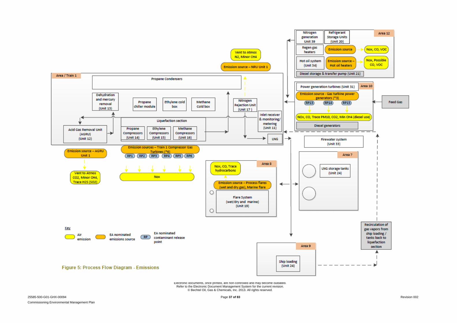
Security Level 2 Electronic documents, once printed, are non-controlled and may become outdated.
Refer to the Electronic Document Management System for the current revision. © Bechtel Oil, Gas & Chemicals, Inc. 2013. All rights reserved.
25585-500-G01-GHX-00094 Page 37 of 83 Revision 002
Commissioning Environmental Management Plan
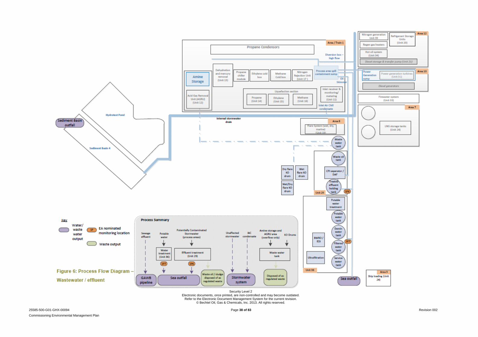
Security Level 2 Electronic documents, once printed, are non-controlled and may become outdated.
Refer to the Electronic Document Management System for the current revision. © Bechtel Oil, Gas & Chemicals, Inc. 2013. All rights reserved.
25585-500-G01-GHX-00094 Page 38 of 83 Revision 002
Commissioning Environmental Management Plan
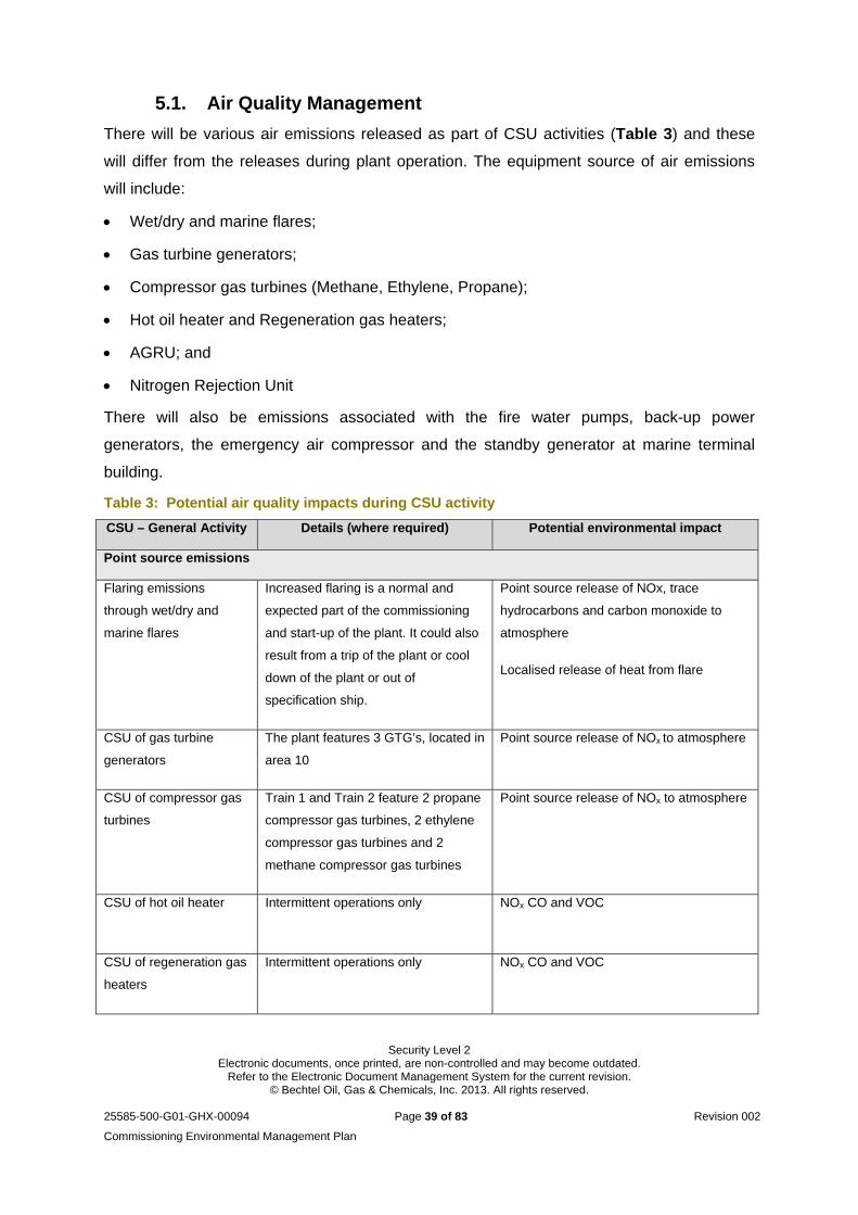
Security Level 2 Electronic documents, once printed, are non-controlled and may become outdated.
Refer to the Electronic Document Management System for the current revision. © Bechtel Oil, Gas & Chemicals, Inc. 2013. All rights reserved.
25585-500-G01-GHX-00094 Page 39 of 83 Revision 002
Commissioning Environmental Management Plan
5.1. Air Quality Management
There will be various air emissions released as part of CSU activities (Table 3) and these
will differ from the releases during plant operation. The equipment source of air emissions
will include:
Wet/dry and marine flares;
Gas turbine generators;
Compressor gas turbines (Methane, Ethylene, Propane);
Hot oil heater and Regeneration gas heaters;
AGRU; and
Nitrogen Rejection Unit
There will also be emissions associated with the fire water pumps, back-up power
generators, the emergency air compressor and the standby generator at marine terminal
building.
Table 3: Potential air quality impacts during CSU activity
CSU – General Activity Details (where required) Potential environmental impact
Point source emissions
Flaring emissions
through wet/dry and
marine flares
Increased flaring is a normal and
expected part of the commissioning
and start-up of the plant. It could also
result from a trip of the plant or cool
down of the plant or out of
specification ship.
Point source release of NOx, trace
hydrocarbons and carbon monoxide to
atmosphere
Localised release of heat from flare
CSU of gas turbine
generators
The plant features 3 GTG’s, located in
area 10
Point source release of NOx to atmosphere
CSU of compressor gas
turbines
Train 1 and Train 2 feature 2 propane
compressor gas turbines, 2 ethylene
compressor gas turbines and 2
methane compressor gas turbines
Point source release of NOx to atmosphere
CSU of hot oil heater Intermittent operations only
NOx CO and VOC
CSU of regeneration gas
heaters
Intermittent operations only NOx CO and VOC
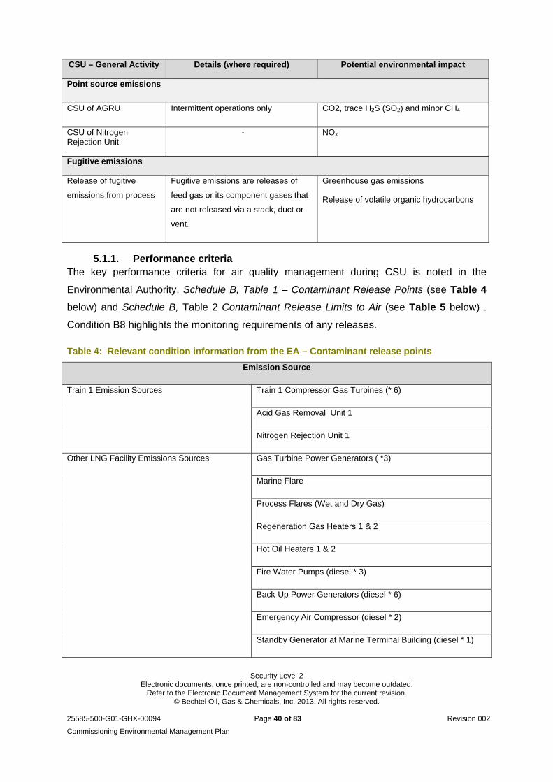
Security Level 2 Electronic documents, once printed, are non-controlled and may become outdated.
Refer to the Electronic Document Management System for the current revision. © Bechtel Oil, Gas & Chemicals, Inc. 2013. All rights reserved.
25585-500-G01-GHX-00094 Page 40 of 83 Revision 002
Commissioning Environmental Management Plan
CSU – General Activity Details (where required) Potential environmental impact
Point source emissions
CSU of AGRU Intermittent operations only CO2, trace H2S (SO2) and minor CH4
CSU of Nitrogen Rejection Unit
- NOx
Fugitive emissions
Release of fugitive
emissions from process
Fugitive emissions are releases of
feed gas or its component gases that
are not released via a stack, duct or
vent.
Greenhouse gas emissions
Release of volatile organic hydrocarbons
5.1.1. Performance criteria The key performance criteria for air quality management during CSU is noted in the
Environmental Authority, Schedule B, Table 1 – Contaminant Release Points (see Table 4
below) and Schedule B, Table 2 Contaminant Release Limits to Air (see Table 5 below) .
Condition B8 highlights the monitoring requirements of any releases.
Table 4: Relevant condition information from the EA – Contaminant release points
Emission Source
Train 1 Emission Sources Train 1 Compressor Gas Turbines (* 6)
Acid Gas Removal Unit 1
Nitrogen Rejection Unit 1
Other LNG Facility Emissions Sources Gas Turbine Power Generators ( *3)
Marine Flare
Process Flares (Wet and Dry Gas)
Regeneration Gas Heaters 1 & 2
Hot Oil Heaters 1 & 2
Fire Water Pumps (diesel * 3)
Back-Up Power Generators (diesel * 6)
Emergency Air Compressor (diesel * 2)
Standby Generator at Marine Terminal Building (diesel * 1)
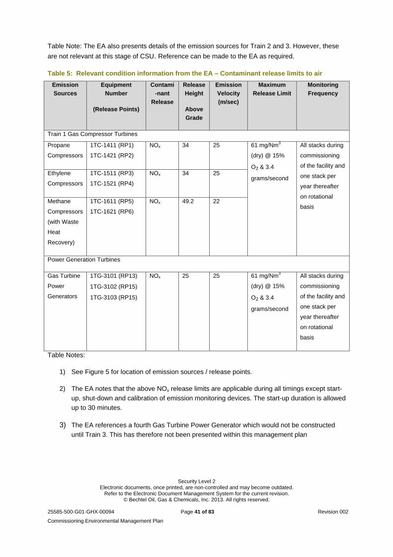
Security Level 2 Electronic documents, once printed, are non-controlled and may become outdated.
Refer to the Electronic Document Management System for the current revision. © Bechtel Oil, Gas & Chemicals, Inc. 2013. All rights reserved.
25585-500-G01-GHX-00094 Page 41 of 83 Revision 002
Commissioning Environmental Management Plan
Table Note: The EA also presents details of the emission sources for Train 2 and 3. However, these
are not relevant at this stage of CSU. Reference can be made to the EA as required.
Table 5: Relevant condition information from the EA – Contaminant release limits to air
Emission
Sources
Equipment
Number
(Release Points)
Contami
-nant
Release
Release
Height
Above
Grade
Emission
Velocity
(m/sec)
Maximum
Release Limit
Monitoring
Frequency
Train 1 Gas Compressor Turbines
Propane
Compressors
1TC-1411 (RP1)
1TC-1421 (RP2)
NOx
34 25 61 mg/Nm3
(dry) @ 15%
O2 & 3.4
grams/second
All stacks during
commissioning
of the facility and
one stack per
year thereafter
on rotational
basis
Ethylene
Compressors
1TC-1511 (RP3)
1TC-1521 (RP4)
NOx
34 25
Methane
Compressors
(with Waste
Heat
Recovery)
1TC-1611 (RP5)
1TC-1621 (RP6)
NOx
49.2 22
Power Generation Turbines
Gas Turbine
Power
Generators
1TG-3101 (RP13)
1TG-3102 (RP15)
1TG-3103 (RP15)
NOx
25 25 61 mg/Nm3
(dry) @ 15%
O2 & 3.4
grams/second
All stacks during
commissioning
of the facility and
one stack per
year thereafter
on rotational
basis
Table Notes:
1) See Figure 5 for location of emission sources / release points.
2) The EA notes that the above NOx release limits are applicable during all timings except start-
up, shut-down and calibration of emission monitoring devices. The start-up duration is allowed
up to 30 minutes.
3) The EA references a fourth Gas Turbine Power Generator which would not be constructed
until Train 3. This has therefore not been presented within this management plan
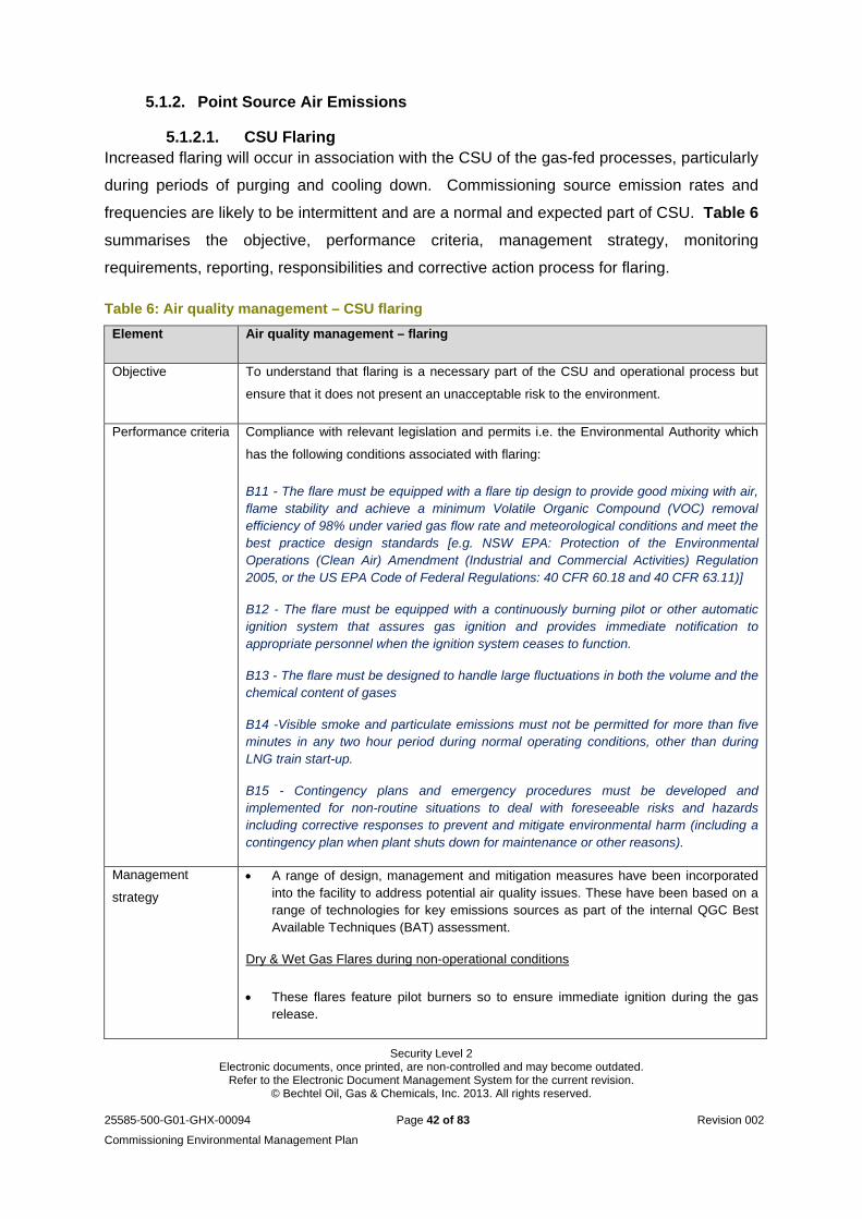
Security Level 2 Electronic documents, once printed, are non-controlled and may become outdated.
Refer to the Electronic Document Management System for the current revision. © Bechtel Oil, Gas & Chemicals, Inc. 2013. All rights reserved.
25585-500-G01-GHX-00094 Page 42 of 83 Revision 002
Commissioning Environmental Management Plan
5.1.2. Point Source Air Emissions
5.1.2.1. CSU Flaring Increased flaring will occur in association with the CSU of the gas-fed processes, particularly
during periods of purging and cooling down. Commissioning source emission rates and
frequencies are likely to be intermittent and are a normal and expected part of CSU. Table 6
summarises the objective, performance criteria, management strategy, monitoring
requirements, reporting, responsibilities and corrective action process for flaring.
Table 6: Air quality management – CSU flaring
Element Air quality management – flaring
Objective To understand that flaring is a necessary part of the CSU and operational process but
ensure that it does not present an unacceptable risk to the environment.
Performance criteria Compliance with relevant legislation and permits i.e. the Environmental Authority which
has the following conditions associated with flaring:
B11 - The flare must be equipped with a flare tip design to provide good mixing with air, flame stability and achieve a minimum Volatile Organic Compound (VOC) removal efficiency of 98% under varied gas flow rate and meteorological conditions and meet the best practice design standards [e.g. NSW EPA: Protection of the Environmental Operations (Clean Air) Amendment (Industrial and Commercial Activities) Regulation 2005, or the US EPA Code of Federal Regulations: 40 CFR 60.18 and 40 CFR 63.11)]
B12 - The flare must be equipped with a continuously burning pilot or other automatic ignition system that assures gas ignition and provides immediate notification to appropriate personnel when the ignition system ceases to function.
B13 - The flare must be designed to handle large fluctuations in both the volume and the chemical content of gases
B14 -Visible smoke and particulate emissions must not be permitted for more than five minutes in any two hour period during normal operating conditions, other than during LNG train start-up.
B15 - Contingency plans and emergency procedures must be developed and implemented for non-routine situations to deal with foreseeable risks and hazards including corrective responses to prevent and mitigate environmental harm (including a contingency plan when plant shuts down for maintenance or other reasons).
Management
strategy
A range of design, management and mitigation measures have been incorporated into the facility to address potential air quality issues. These have been based on a range of technologies for key emissions sources as part of the internal QGC Best Available Techniques (BAT) assessment.
Dry & Wet Gas Flares during non-operational conditions
These flares feature pilot burners so to ensure immediate ignition during the gas release.
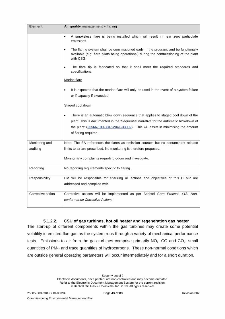
Security Level 2 Electronic documents, once printed, are non-controlled and may become outdated.
Refer to the Electronic Document Management System for the current revision. © Bechtel Oil, Gas & Chemicals, Inc. 2013. All rights reserved.
25585-500-G01-GHX-00094 Page 43 of 83 Revision 002
Commissioning Environmental Management Plan
Element Air quality management – flaring
A smokeless flare is being installed which will result in near zero particulate emissions.
The flaring system shall be commissioned early in the program, and be functionally available (e.g. flare pilots being operational) during the commissioning of the plant with CSG.
The flare tip is fabricated so that it shall meet the required standards and specifications.
Marine flare
It is expected that the marine flare will only be used in the event of a system failure
or if capacity if exceeded.
Staged cool down
There is an automatic blow down sequence that applies to staged cool down of the
plant. This is documented in the ‘Sequential narrative for the automatic blowdown of
the plant’ (25566-100-3DR-V04F-33002). This will assist in minimising the amount
of flaring required.
Monitoring and
auditing
Note: The EA references the flares as emission sources but no contaminant release
limits to air are prescribed. No monitoring is therefore proposed.
Monitor any complaints regarding odour and investigate.
Reporting No reporting requirements specific to flaring.
Responsibility EM will be responsible for ensuring all actions and objectives of this CEMP are
addressed and complied with.
Corrective action Corrective actions will be implemented as per Bechtel Core Process 413: Non-
conformance Corrective Actions.
5.1.2.2. CSU of gas turbines, hot oil heater and regeneration gas heater The start-up of different components within the gas turbines may create some potential
volatility in emitted flue gas as the system runs through a variety of mechanical performance
tests. Emissions to air from the gas turbines comprise primarily NOx, CO and CO2, small
quantities of PM10 and trace quantities of hydrocarbons. These non-normal conditions which
are outside general operating parameters will occur intermediately and for a short duration.
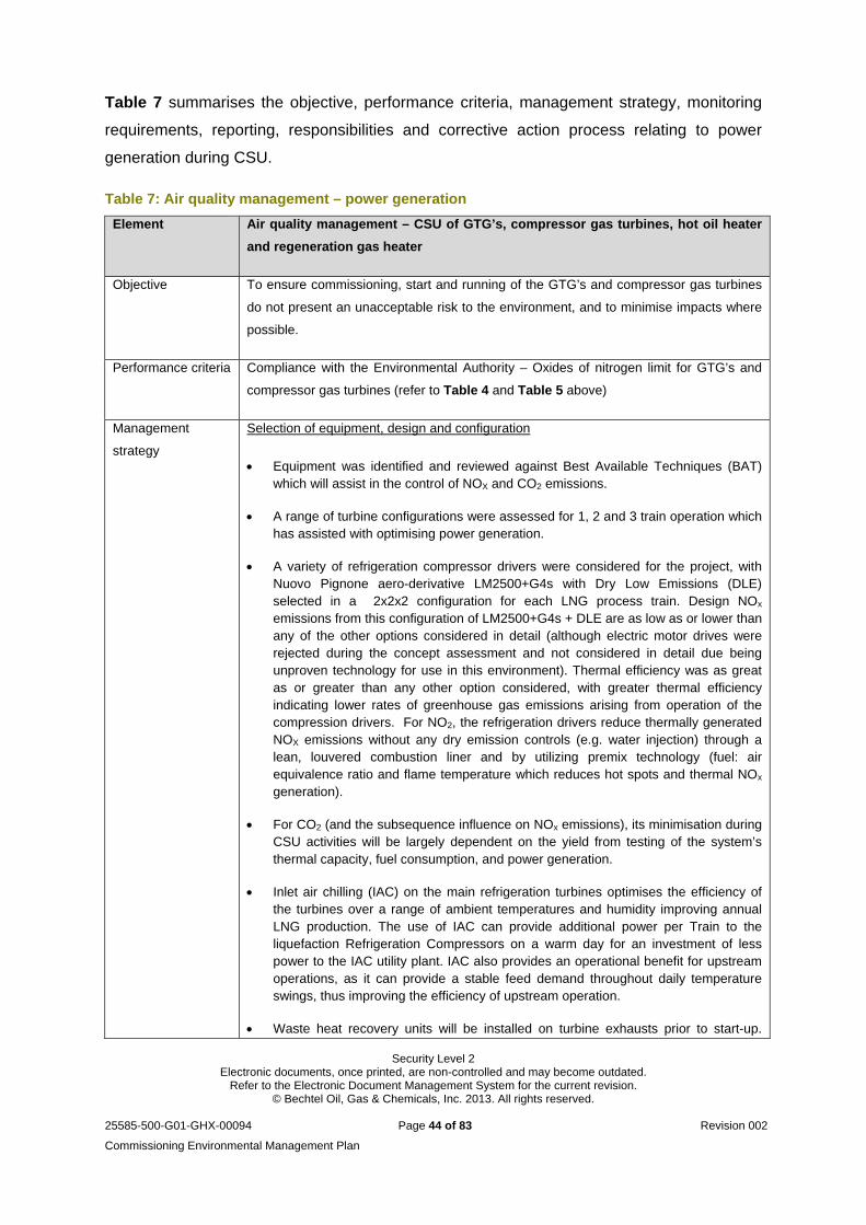
Security Level 2 Electronic documents, once printed, are non-controlled and may become outdated.
Refer to the Electronic Document Management System for the current revision. © Bechtel Oil, Gas & Chemicals, Inc. 2013. All rights reserved.
25585-500-G01-GHX-00094 Page 44 of 83 Revision 002
Commissioning Environmental Management Plan
Table 7 summarises the objective, performance criteria, management strategy, monitoring
requirements, reporting, responsibilities and corrective action process relating to power
generation during CSU.
Table 7: Air quality management – power generation
Element Air quality management – CSU of GTG’s, compressor gas turbines, hot oil heater
and regeneration gas heater
Objective To ensure commissioning, start and running of the GTG’s and compressor gas turbines
do not present an unacceptable risk to the environment, and to minimise impacts where
possible.
Performance criteria Compliance with the Environmental Authority – Oxides of nitrogen limit for GTG’s and
compressor gas turbines (refer to Table 4 and Table 5 above)
Management
strategy
Selection of equipment, design and configuration
Equipment was identified and reviewed against Best Available Techniques (BAT) which will assist in the control of NOX and CO2 emissions.
A range of turbine configurations were assessed for 1, 2 and 3 train operation which has assisted with optimising power generation.
A variety of refrigeration compressor drivers were considered for the project, with Nuovo Pignone aero-derivative LM2500+G4s with Dry Low Emissions (DLE) selected in a 2x2x2 configuration for each LNG process train. Design NOx emissions from this configuration of LM2500+G4s + DLE are as low as or lower than any of the other options considered in detail (although electric motor drives were rejected during the concept assessment and not considered in detail due being unproven technology for use in this environment). Thermal efficiency was as great as or greater than any other option considered, with greater thermal efficiency indicating lower rates of greenhouse gas emissions arising from operation of the compression drivers. For NO2, the refrigeration drivers reduce thermally generated NOX emissions without any dry emission controls (e.g. water injection) through a lean, louvered combustion liner and by utilizing premix technology (fuel: air equivalence ratio and flame temperature which reduces hot spots and thermal NOx
generation).
For CO2 (and the subsequence influence on NOx emissions), its minimisation during CSU activities will be largely dependent on the yield from testing of the system’s thermal capacity, fuel consumption, and power generation.
Inlet air chilling (IAC) on the main refrigeration turbines optimises the efficiency of the turbines over a range of ambient temperatures and humidity improving annual LNG production. The use of IAC can provide additional power per Train to the liquefaction Refrigeration Compressors on a warm day for an investment of less power to the IAC utility plant. IAC also provides an operational benefit for upstream operations, as it can provide a stable feed demand throughout daily temperature swings, thus improving the efficiency of upstream operation.
Waste heat recovery units will be installed on turbine exhausts prior to start-up.
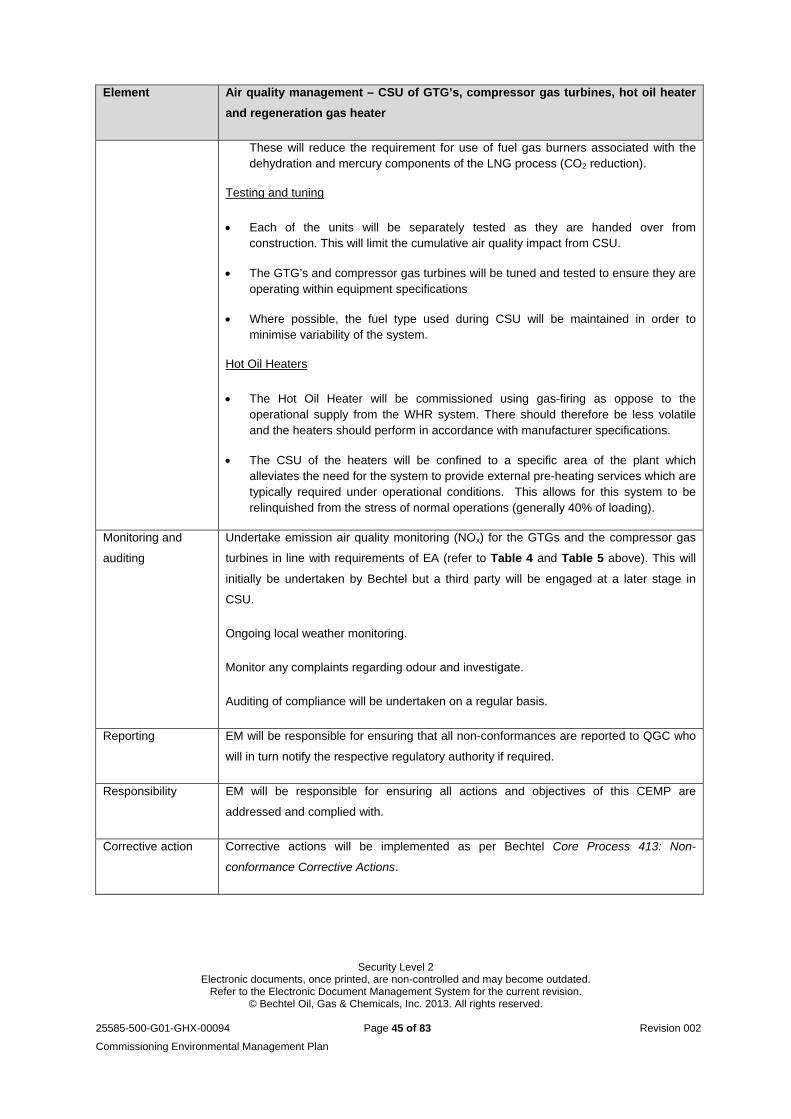
Security Level 2 Electronic documents, once printed, are non-controlled and may become outdated.
Refer to the Electronic Document Management System for the current revision. © Bechtel Oil, Gas & Chemicals, Inc. 2013. All rights reserved.
25585-500-G01-GHX-00094 Page 45 of 83 Revision 002
Commissioning Environmental Management Plan
Element Air quality management – CSU of GTG’s, compressor gas turbines, hot oil heater
and regeneration gas heater
These will reduce the requirement for use of fuel gas burners associated with the dehydration and mercury components of the LNG process (CO2 reduction).
Testing and tuning
Each of the units will be separately tested as they are handed over from construction. This will limit the cumulative air quality impact from CSU.
The GTG’s and compressor gas turbines will be tuned and tested to ensure they are operating within equipment specifications
Where possible, the fuel type used during CSU will be maintained in order to minimise variability of the system.
Hot Oil Heaters
The Hot Oil Heater will be commissioned using gas-firing as oppose to the operational supply from the WHR system. There should therefore be less volatile and the heaters should perform in accordance with manufacturer specifications.
The CSU of the heaters will be confined to a specific area of the plant which alleviates the need for the system to provide external pre-heating services which are typically required under operational conditions. This allows for this system to be relinquished from the stress of normal operations (generally 40% of loading).
Monitoring and
auditing
Undertake emission air quality monitoring (NOx) for the GTGs and the compressor gas
turbines in line with requirements of EA (refer to Table 4 and Table 5 above). This will
initially be undertaken by Bechtel but a third party will be engaged at a later stage in
CSU.
Ongoing local weather monitoring.
Monitor any complaints regarding odour and investigate.
Auditing of compliance will be undertaken on a regular basis.
Reporting EM will be responsible for ensuring that all non-conformances are reported to QGC who
will in turn notify the respective regulatory authority if required.
Responsibility EM will be responsible for ensuring all actions and objectives of this CEMP are
addressed and complied with.
Corrective action Corrective actions will be implemented as per Bechtel Core Process 413: Non-
conformance Corrective Actions.
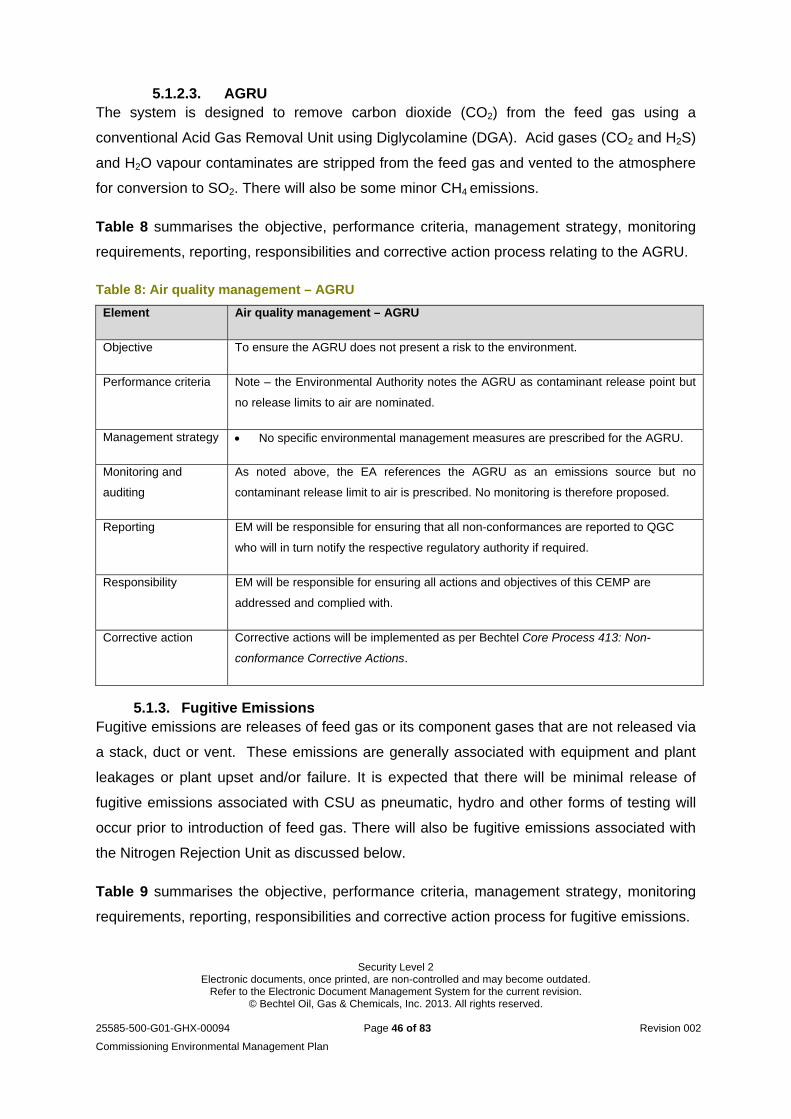
Security Level 2 Electronic documents, once printed, are non-controlled and may become outdated.
Refer to the Electronic Document Management System for the current revision. © Bechtel Oil, Gas & Chemicals, Inc. 2013. All rights reserved.
25585-500-G01-GHX-00094 Page 46 of 83 Revision 002
Commissioning Environmental Management Plan
5.1.2.3. AGRU The system is designed to remove carbon dioxide (CO2) from the feed gas using a
conventional Acid Gas Removal Unit using Diglycolamine (DGA). Acid gases (CO2 and H2S)
and H2O vapour contaminates are stripped from the feed gas and vented to the atmosphere
for conversion to SO2. There will also be some minor CH4 emissions.
Table 8 summarises the objective, performance criteria, management strategy, monitoring
requirements, reporting, responsibilities and corrective action process relating to the AGRU.
Table 8: Air quality management – AGRU
Element Air quality management – AGRU
Objective To ensure the AGRU does not present a risk to the environment.
Performance criteria Note – the Environmental Authority notes the AGRU as contaminant release point but
no release limits to air are nominated.
Management strategy No specific environmental management measures are prescribed for the AGRU.
Monitoring and
auditing
As noted above, the EA references the AGRU as an emissions source but no
contaminant release limit to air is prescribed. No monitoring is therefore proposed.
Reporting EM will be responsible for ensuring that all non-conformances are reported to QGC
who will in turn notify the respective regulatory authority if required.
Responsibility EM will be responsible for ensuring all actions and objectives of this CEMP are
addressed and complied with.
Corrective action Corrective actions will be implemented as per Bechtel Core Process 413: Non-
conformance Corrective Actions.
5.1.3. Fugitive Emissions Fugitive emissions are releases of feed gas or its component gases that are not released via
a stack, duct or vent. These emissions are generally associated with equipment and plant
leakages or plant upset and/or failure. It is expected that there will be minimal release of
fugitive emissions associated with CSU as pneumatic, hydro and other forms of testing will
occur prior to introduction of feed gas. There will also be fugitive emissions associated with
the Nitrogen Rejection Unit as discussed below.
Table 9 summarises the objective, performance criteria, management strategy, monitoring
requirements, reporting, responsibilities and corrective action process for fugitive emissions.
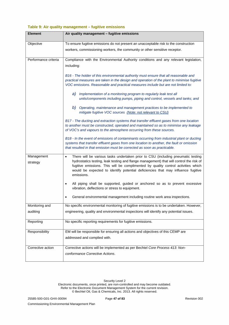
Security Level 2 Electronic documents, once printed, are non-controlled and may become outdated.
Refer to the Electronic Document Management System for the current revision. © Bechtel Oil, Gas & Chemicals, Inc. 2013. All rights reserved.
25585-500-G01-GHX-00094 Page 47 of 83 Revision 002
Commissioning Environmental Management Plan
Table 9: Air quality management – fugitive emissions
Element Air quality management – fugitive emissions
Objective To ensure fugitive emissions do not present an unacceptable risk to the construction
workers, commissioning workers, the community or other sensitive receptor.
Performance criteria Compliance with the Environmental Authority conditions and any relevant legislation,
including:
B16 - The holder of this environmental authority must ensure that all reasonable and practical measures are taken in the design and operation of the plant to minimise fugitive VOC emissions. Reasonable and practical measures include but are not limited to:
a) Implementation of a monitoring program to regularly leak test all units/components including pumps, piping and control, vessels and tanks; and
b) Operating, maintenance and management practices to be implemented to mitigate fugitive VOC sources (Note: not relevant to CSU)
B17 - The ducting and extraction systems that transfer effluent gases from one location to another must be constructed, operated and maintained so as to minimise any leakage of VOC’s and vapours to the atmosphere occurring from these sources.
B18 - In the event of emissions of contaminants occurring from industrial plant or ducting systems that transfer effluent gases from one location to another, the fault or omission that resulted in that emission must be corrected as soon as practicable.
Management
strategy
There will be various tasks undertaken prior to CSU (including pneumatic testing hydrostatics testing, leak testing and flange management) that will control the risk of fugitive emissions. This will be complimented by quality control activities which would be expected to identify potential deficiencies that may influence fugitive emissions.
All piping shall be supported, guided or anchored so as to prevent excessive vibration, deflections or stress to equipment.
General environmental management including routine work area inspections.
Monitoring and
auditing
No specific environmental monitoring of fugitive emissions is to be undertaken. However,
engineering, quality and environmental inspections will identify any potential issues.
Reporting No specific reporting requirements for fugitive emissions.
Responsibility EM will be responsible for ensuring all actions and objectives of this CEMP are
addressed and complied with.
Corrective action Corrective actions will be implemented as per Bechtel Core Process 413: Non-
conformance Corrective Actions.
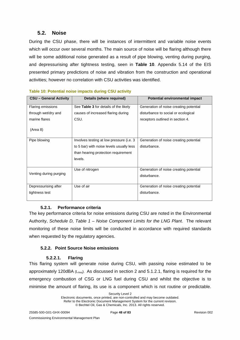
Security Level 2 Electronic documents, once printed, are non-controlled and may become outdated.
Refer to the Electronic Document Management System for the current revision. © Bechtel Oil, Gas & Chemicals, Inc. 2013. All rights reserved.
25585-500-G01-GHX-00094 Page 48 of 83 Revision 002
Commissioning Environmental Management Plan
5.2. Noise
During the CSU phase, there will be instances of intermittent and variable noise events
which will occur over several months. The main source of noise will be flaring although there
will be some additional noise generated as a result of pipe blowing, venting during purging,
and depressurising after tightness testing, seen in Table 10. Appendix 5.14 of the EIS
presented primary predictions of noise and vibration from the construction and operational
activities; however no correlation with CSU activities was identified.
Table 10: Potential noise impacts during CSU activity
CSU – General Activity Details (where required) Potential environmental impact
Flaring emissions
through wet/dry and
marine flares
(Area 8)
See Table 3 for details of the likely
causes of increased flaring during
CSU.
Generation of noise creating potential
disturbance to social or ecological
receptors outlined in section 4.
Pipe blowing Involves testing at low pressure (i.e. 3
to 5 bar) with noise levels usually less
than hearing protection requirement
levels.
Generation of noise creating potential
disturbance.
Venting during purging
Use of nitrogen Generation of noise creating potential
disturbance.
Depressurising after
tightness test
Use of air Generation of noise creating potential
disturbance.
5.2.1. Performance criteria The key performance criteria for noise emissions during CSU are noted in the Environmental
Authority, Schedule D, Table 1 – Noise Component Limits for the LNG Plant. The relevant
monitoring of these noise limits will be conducted in accordance with required standards
when requested by the regulatory agencies.
5.2.2. Point Source Noise emissions
5.2.2.1. Flaring This flaring system will generate noise during CSU, with passing noise estimated to be
approximately 120dBA (LAeq). As discussed in section 2 and 5.1.2.1, flaring is required for the
emergency combustion of CSG or LNG fuel during CSU and whilst the objective is to
minimise the amount of flaring, its use is a component which is not routine or predictable.

Security Level 2 Electronic documents, once printed, are non-controlled and may become outdated.
Refer to the Electronic Document Management System for the current revision. © Bechtel Oil, Gas & Chemicals, Inc. 2013. All rights reserved.
25585-500-G01-GHX-00094 Page 49 of 83 Revision 002
Commissioning Environmental Management Plan
Plausible mitigation techniques and management measures are therefore limited. Table 11
summarises the objective, performance criteria, management strategy, monitoring
requirements, reporting, responsibilities and corrective action process for flaring.
Table 11: Noise emission management - flaring
Element Noise management - flaring
Objective To ensure the flaring commissioning activities do not present an unacceptable nuisance
to any sensitive or commercial place and to minimise any potential noise impacts as a
result of CSU activities.
Performance criteria Compliance with the Environmental Authority conditions and any relevant legislation,
including:
D1 - Noise from the construction or operation of LNG plant activities must not cause environmental nuisance at any sensitive place or commercial place.
D2 - When requested by the administrating authority, noise monitoring must be
undertaken within a reasonable and practicable timeframe nominated by the
administrating authority to investigate any complaint (which is neither frivolous nor
vexatious nor based on mistaken belief in the opinion of the authorised officer) of
environmental nuisance at sensitive place or commercial place, and the results must be
notified within 14 days to the administrating authority following completion of monitoring.
Zero non-compliances with project specific noise criteria at noise sensitive receptors and
with the EPP (Noise)
Number of noise complaints from local community
Management
strategy
Any planned fuel release, and subsequent flaring, will be undertaken during daytime where possible. However, the lengthy time required to undertake and complete flaring may not be possible within dedicated times.
Flaring activities will be conducted in as short a time as possible but with appropriate consideration for safety.
Monitoring and
auditing
If requested by DEHP, monitoring will be conducted as per Schedule D, Table 1 – Noise
Component Limits for the LNG Plant of the EA, or as directed by the regulatory agency.
Any noise monitoring will occur at the source of the noise complaint, and will be
performed in accordance with the latest edition of DERM Noise Management Manual
and AS1055.
Reporting EM will be responsible for ensuring that all non-conformances are reported to QGC who
will in turn notify the respective regulatory authority if required.
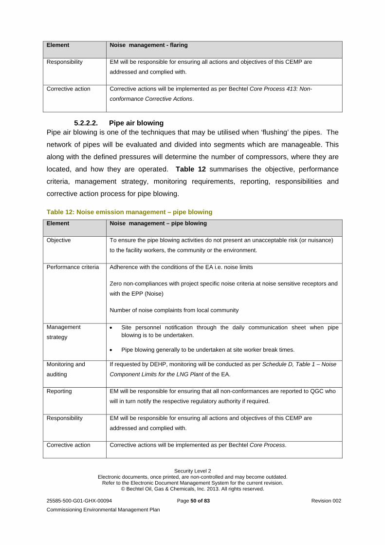
Security Level 2 Electronic documents, once printed, are non-controlled and may become outdated.
Refer to the Electronic Document Management System for the current revision. © Bechtel Oil, Gas & Chemicals, Inc. 2013. All rights reserved.
25585-500-G01-GHX-00094 Page 50 of 83 Revision 002
Commissioning Environmental Management Plan
Element Noise management - flaring
Responsibility EM will be responsible for ensuring all actions and objectives of this CEMP are
addressed and complied with.
Corrective action Corrective actions will be implemented as per Bechtel Core Process 413: Non-
conformance Corrective Actions.
5.2.2.2. Pipe air blowing Pipe air blowing is one of the techniques that may be utilised when ‘flushing’ the pipes. The
network of pipes will be evaluated and divided into segments which are manageable. This
along with the defined pressures will determine the number of compressors, where they are
located, and how they are operated. Table 12 summarises the objective, performance
criteria, management strategy, monitoring requirements, reporting, responsibilities and
corrective action process for pipe blowing.
Table 12: Noise emission management – pipe blowing
Element Noise management – pipe blowing
Objective To ensure the pipe blowing activities do not present an unacceptable risk (or nuisance)
to the facility workers, the community or the environment.
Performance criteria Adherence with the conditions of the EA i.e. noise limits
Zero non-compliances with project specific noise criteria at noise sensitive receptors and
with the EPP (Noise)
Number of noise complaints from local community
Management
strategy
Site personnel notification through the daily communication sheet when pipe blowing is to be undertaken.
Pipe blowing generally to be undertaken at site worker break times.
Monitoring and
auditing
If requested by DEHP, monitoring will be conducted as per Schedule D, Table 1 – Noise
Component Limits for the LNG Plant of the EA.
Reporting EM will be responsible for ensuring that all non-conformances are reported to QGC who
will in turn notify the respective regulatory authority if required.
Responsibility EM will be responsible for ensuring all actions and objectives of this CEMP are
addressed and complied with.
Corrective action Corrective actions will be implemented as per Bechtel Core Process.
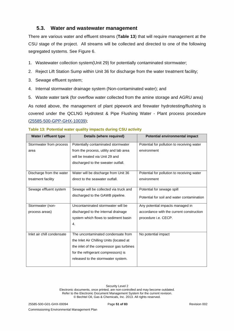
Security Level 2 Electronic documents, once printed, are non-controlled and may become outdated.
Refer to the Electronic Document Management System for the current revision. © Bechtel Oil, Gas & Chemicals, Inc. 2013. All rights reserved.
25585-500-G01-GHX-00094 Page 51 of 83 Revision 002
Commissioning Environmental Management Plan
5.3. Water and wastewater management
There are various water and effluent streams (Table 13) that will require management at the
CSU stage of the project. All streams will be collected and directed to one of the following
segregated systems. See Figure 6.
1. Wastewater collection system(Unit 29) for potentially contaminated stormwater;
2. Reject Lift Station Sump within Unit 36 for discharge from the water treatment facility;
3. Sewage effluent system;
4. Internal stormwater drainage system (Non-contaminated water); and
5. Waste water tank (for overflow water collected from the amine storage and AGRU area)
As noted above, the management of plant pipework and firewater hydrotesting/flushing is
covered under the QCLNG Hydrotest & Pipe Flushing Water - Plant process procedure
(25585-500-GPP-GHX-10039);
Table 13: Potential water quality impacts during CSU activity
Water / effluent type Details (where required) Potential environmental impact
Stormwater from process
area
Potentially contaminated stormwater
from the process, utility and lab area
will be treated via Unit 29 and
discharged to the sweater outfall.
Potential for pollution to receiving water
environment
Discharge from the water
treatment facility
Water will be discharge from Unit 36
direct to the seawater outfall.
Potential for pollution to receiving water
environment
Sewage effluent system Sewage will be collected via truck and
discharged to the GAWB pipeline.
Potential for sewage spill
Potential for soil and water contamination
Stormwater (non-
process areas)
Uncontaminated stormwater will be
discharged to the internal drainage
system which flows to sediment basin
4.
Any potential impacts managed in
accordance with the current construction
procedure i.e. CECP.
Inlet air chill condensate
The uncontaminated condensate from
the Inlet Air Chilling Units (located at
the inlet of the compressor gas turbines
for the refrigerant compressors) is
released to the stormwater system.
No potential impact
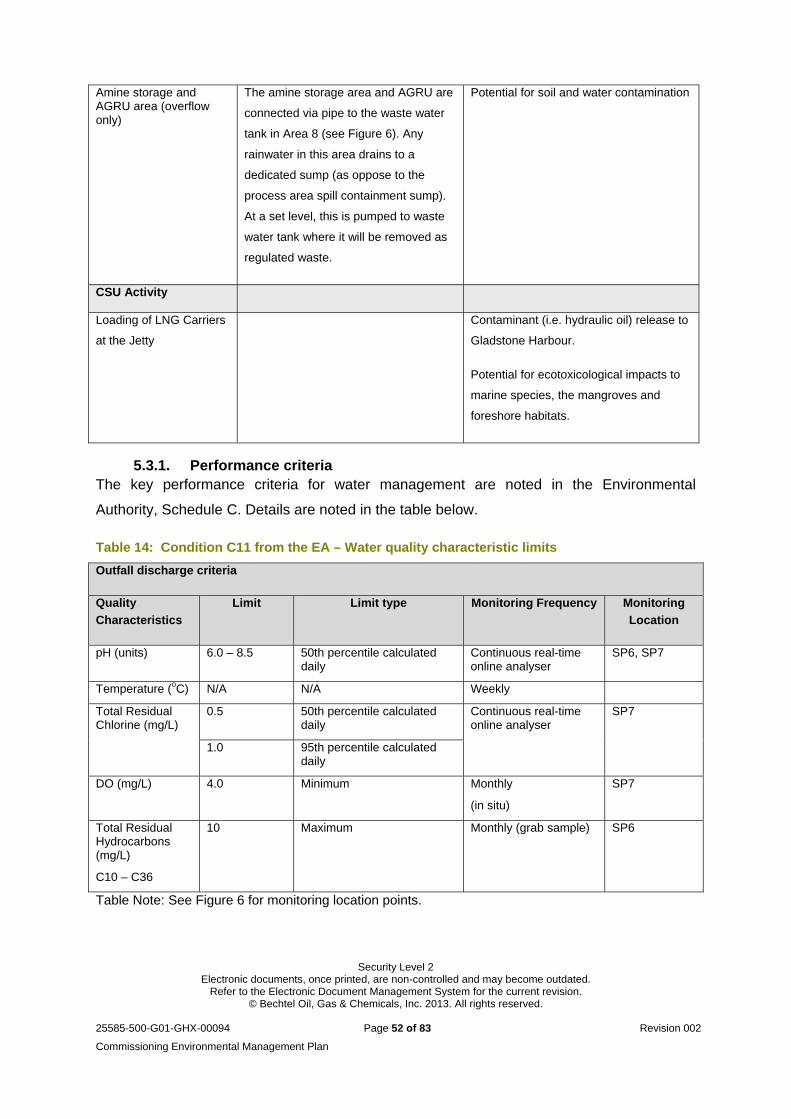
Security Level 2 Electronic documents, once printed, are non-controlled and may become outdated.
Refer to the Electronic Document Management System for the current revision. © Bechtel Oil, Gas & Chemicals, Inc. 2013. All rights reserved.
25585-500-G01-GHX-00094 Page 52 of 83 Revision 002
Commissioning Environmental Management Plan
Amine storage and AGRU area (overflow only)
The amine storage area and AGRU are
connected via pipe to the waste water
tank in Area 8 (see Figure 6). Any
rainwater in this area drains to a
dedicated sump (as oppose to the
process area spill containment sump).
At a set level, this is pumped to waste
water tank where it will be removed as
regulated waste.
Potential for soil and water contamination
CSU Activity
Loading of LNG Carriers
at the Jetty
Contaminant (i.e. hydraulic oil) release to
Gladstone Harbour.
Potential for ecotoxicological impacts to
marine species, the mangroves and
foreshore habitats.
5.3.1. Performance criteria The key performance criteria for water management are noted in the Environmental
Authority, Schedule C. Details are noted in the table below.
Table 14: Condition C11 from the EA – Water quality characteristic limits
Outfall discharge criteria
Quality
Characteristics
Limit Limit type Monitoring Frequency Monitoring
Location
pH (units) 6.0 – 8.5 50th percentile calculated daily
Continuous real-time online analyser
SP6, SP7
Temperature (oC) N/A N/A Weekly
Total Residual Chlorine (mg/L)
0.5 50th percentile calculated daily
Continuous real-time online analyser
SP7
1.0 95th percentile calculated daily
DO (mg/L) 4.0 Minimum Monthly
(in situ)
SP7
Total Residual Hydrocarbons (mg/L)
C10 – C36
10 Maximum Monthly (grab sample) SP6
Table Note: See Figure 6 for monitoring location points.
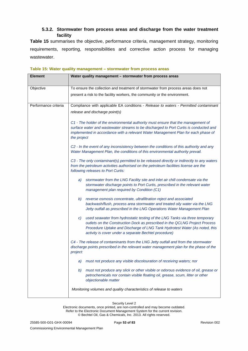
Security Level 2 Electronic documents, once printed, are non-controlled and may become outdated.
Refer to the Electronic Document Management System for the current revision. © Bechtel Oil, Gas & Chemicals, Inc. 2013. All rights reserved.
25585-500-G01-GHX-00094 Page 53 of 83 Revision 002
Commissioning Environmental Management Plan
5.3.2. Stormwater from process areas and discharge from the water treatment facility
Table 15 summarises the objective, performance criteria, management strategy, monitoring
requirements, reporting, responsibilities and corrective action process for managing
wastewater.
Table 15: Water quality management – stormwater from process areas
Element Water quality management – stormwater from process areas
Objective To ensure the collection and treatment of stormwater from process areas does not
present a risk to the facility workers, the community or the environment.
Performance criteria Compliance with applicable EA conditions - Release to waters - Permitted contaminant
release and discharge point(s)
C1 - The holder of the environmental authority must ensure that the management of surface water and wastewater streams to be discharged to Port Curtis is conducted and implemented in accordance with a relevant Water Management Plan for each phase of the project
C2 - In the event of any inconsistency between the conditions of this authority and any Water Management Plan, the conditions of this environmental authority prevail.
C3 - The only contaminant(s) permitted to be released directly or indirectly to any waters from the petroleum activities authorised on the petroleum facilities license are the following releases to Port Curtis:
a) stormwater from the LNG Facility site and inlet air chill condensate via the stormwater discharge points to Port Curtis, prescribed in the relevant water management plan required by Condition (C1)
b) reverse osmosis concentrate, ultrafiltration reject and associated backwash/flush, process area stormwater and treated oily water via the LNG Jetty outfall as prescribed in the LNG Operations Water Management Plan
c) used seawater from hydrostatic testing of the LNG Tanks via three temporary outlets on the Construction Dock as prescribed in the QCLNG Project Process Procedure Uptake and Discharge of LNG Tank Hydrotest Water (As noted, this activity is cover under a separate Bechtel procedure)
C4 - The release of contaminants from the LNG Jetty outfall and from the stormwater discharge points prescribed in the relevant water management plan for the phase of the project:
a) must not produce any visible discolouration of receiving waters; nor
b) must not produce any slick or other visible or odorous evidence of oil, grease or petrochemicals nor contain visible floating oil, grease, scum, litter or other objectionable matter
Monitoring volumes and quality characteristics of release to waters
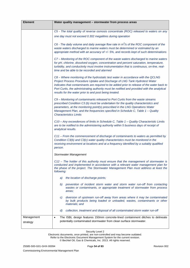
Security Level 2 Electronic documents, once printed, are non-controlled and may become outdated.
Refer to the Electronic Document Management System for the current revision. © Bechtel Oil, Gas & Chemicals, Inc. 2013. All rights reserved.
25585-500-G01-GHX-00094 Page 54 of 83 Revision 002
Commissioning Environmental Management Plan
Element Water quality management – stormwater from process areas
C5 - The total quality of reverse osmosis concentrate (ROC) released to waters on any
one day must not exceed 0.302 megalitres during operation
C6 - The daily volume and daily average flow rate in m3/s of the ROC component of the waste waters discharged to marine waters must be determined or estimated by an appropriate method with an accuracy of +/- 5%, and records kept of such determinations
C7 – Monitoring of the ROC component of the waste waters discharged to marine waters for pH, chlorine, dissolved oxygen, concentration and percent saturation, temperature, turbidity, and conductivity must involve instrumentation that is continuous, on-line, real-time and be able to be recorded and alarmed
C8 – Where monitoring of the hydrostatic test water in accordance with the QCLNG Project Process Procedure Uptake and Discharge of LNG Tank Hydrotest Water indicates that contaminants are required to be added prior to release of the water back to Port Curtis, the administrating authority must be notified and provided with the analytical results for the water prior to and post being treated.
C9 – Monitoring of contaminants released to Port Curtis from the waste streams prescribed Condition C3 (b) must be undertaken for the quality characteristics and parameters, at the monitoring point(s) prescribed in the LNG Operations Water Management Plan, and the frequencies specified in Schedule C, Table 1 – Quality Characteristics Limits
C10 – Any exceedences of limits in Schedule C, Table 1 – Quality Characteristic Limits are to be notified to the administering authority within 5 business days of receipt of analytical results.
C11 – From the commencement of discharge of contaminants to waters as permitted by Condition C3(b) and C3(c) water quality characteristics must be monitored in the receiving environment at locations and at a frequency identified by a suitably qualified person.
Stormwater Management
C12 – The holder of this authority must ensure that the management of stormwater is conducted and implemented in accordance with a relevant water management plan for the phase of the project. The Stormwater Management Plan must address at least the following:
a) the location of discharge points;
b) prevention of incident storm water and storm water run-off from contacting wastes or contaminants, or appropriate treatment of stormwater from process areas;
c) diversion of upstream run-off away from areas where it may be contaminated by bulk products being loaded or unloaded, wastes, contaminants or other materials; and
d) collection, treatment and disposal of all contaminated storm water run-off
Management
strategy
The ISBL design features 150mm concrete-lined containment ditches to delineate potentially contaminated stormwater from clean surface stormwater.
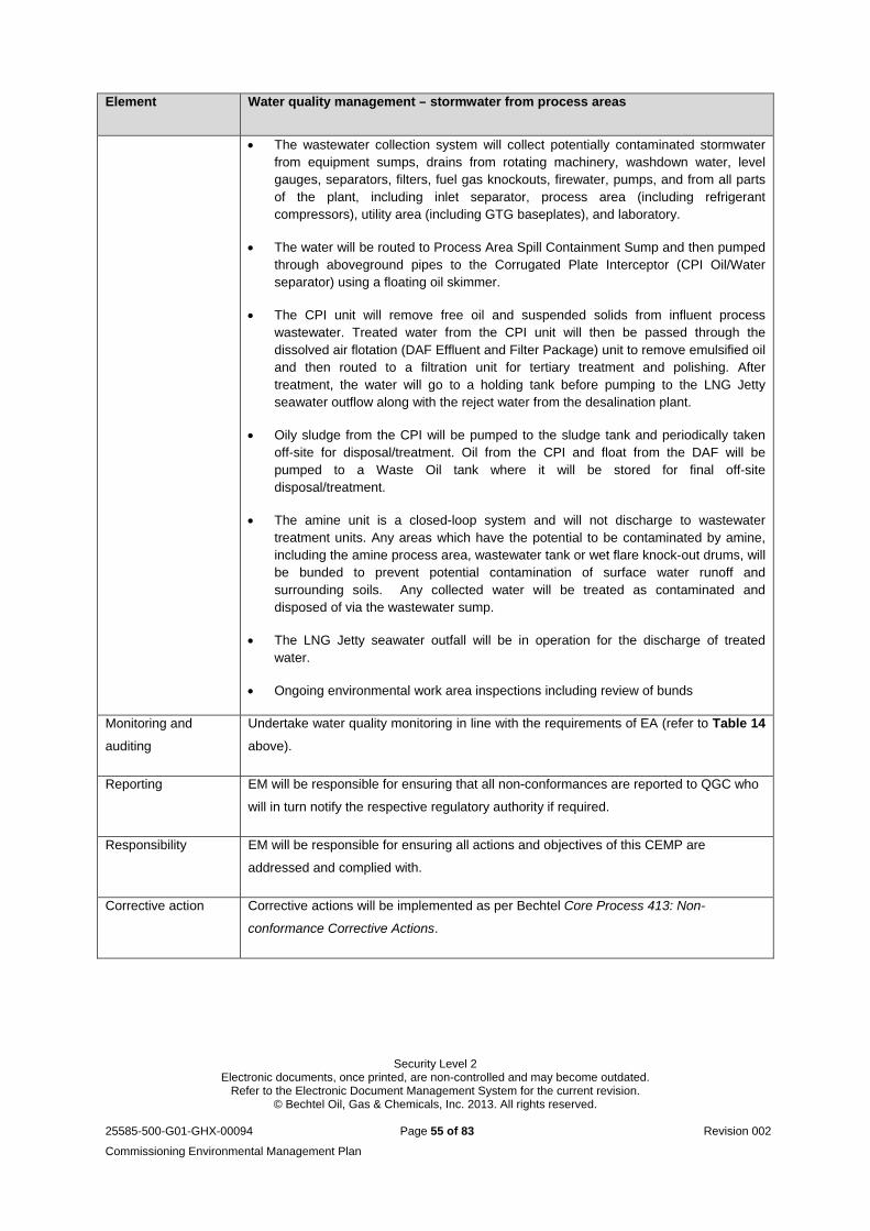
Security Level 2 Electronic documents, once printed, are non-controlled and may become outdated.
Refer to the Electronic Document Management System for the current revision. © Bechtel Oil, Gas & Chemicals, Inc. 2013. All rights reserved.
25585-500-G01-GHX-00094 Page 55 of 83 Revision 002
Commissioning Environmental Management Plan
Element Water quality management – stormwater from process areas
The wastewater collection system will collect potentially contaminated stormwater from equipment sumps, drains from rotating machinery, washdown water, level gauges, separators, filters, fuel gas knockouts, firewater, pumps, and from all parts of the plant, including inlet separator, process area (including refrigerant compressors), utility area (including GTG baseplates), and laboratory.
The water will be routed to Process Area Spill Containment Sump and then pumped through aboveground pipes to the Corrugated Plate Interceptor (CPI Oil/Water separator) using a floating oil skimmer.
The CPI unit will remove free oil and suspended solids from influent process wastewater. Treated water from the CPI unit will then be passed through the dissolved air flotation (DAF Effluent and Filter Package) unit to remove emulsified oil and then routed to a filtration unit for tertiary treatment and polishing. After treatment, the water will go to a holding tank before pumping to the LNG Jetty seawater outflow along with the reject water from the desalination plant.
Oily sludge from the CPI will be pumped to the sludge tank and periodically taken off-site for disposal/treatment. Oil from the CPI and float from the DAF will be pumped to a Waste Oil tank where it will be stored for final off-site disposal/treatment.
The amine unit is a closed-loop system and will not discharge to wastewater treatment units. Any areas which have the potential to be contaminated by amine, including the amine process area, wastewater tank or wet flare knock-out drums, will be bunded to prevent potential contamination of surface water runoff and surrounding soils. Any collected water will be treated as contaminated and disposed of via the wastewater sump.
The LNG Jetty seawater outfall will be in operation for the discharge of treated water.
Ongoing environmental work area inspections including review of bunds
Monitoring and
auditing
Undertake water quality monitoring in line with the requirements of EA (refer to Table 14
above).
Reporting EM will be responsible for ensuring that all non-conformances are reported to QGC who
will in turn notify the respective regulatory authority if required.
Responsibility EM will be responsible for ensuring all actions and objectives of this CEMP are
addressed and complied with.
Corrective action Corrective actions will be implemented as per Bechtel Core Process 413: Non-
conformance Corrective Actions.
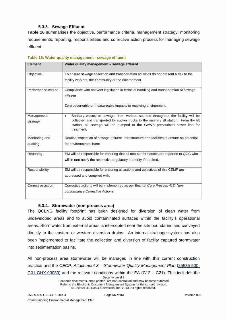
Security Level 2 Electronic documents, once printed, are non-controlled and may become outdated.
Refer to the Electronic Document Management System for the current revision. © Bechtel Oil, Gas & Chemicals, Inc. 2013. All rights reserved.
25585-500-G01-GHX-00094 Page 56 of 83 Revision 002
Commissioning Environmental Management Plan
5.3.3. Sewage Effluent Table 16 summarises the objective, performance criteria, management strategy, monitoring
requirements, reporting, responsibilities and corrective action process for managing sewage
effluent.
Table 16: Water quality management - sewage effluent
Element Water quality management – sewage effluent
Objective To ensure sewage collection and transportation activities do not present a risk to the
facility workers, the community or the environment.
Performance criteria Compliance with relevant legislation in terms of handling and transportation of sewage
effluent
Zero observable or measureable impacts to receiving environment.
Management
strategy
Sanitary waste, or sewage, from various sources throughout the facility will be collected and transported by sucker trucks to the sanitary lift station. From the lift station, all sewage will be pumped to the GAWB pressurised sewer line for treatment.
Monitoring and
auditing
Routine inspection of sewage effluent infrastructure and facilities to ensure no potential
for environmental harm
Reporting EM will be responsible for ensuring that all non-conformances are reported to QGC who
will in turn notify the respective regulatory authority if required.
Responsibility EM will be responsible for ensuring all actions and objectives of this CEMP are
addressed and complied with.
Corrective action Corrective actions will be implemented as per Bechtel Core Process 413: Non-
conformance Corrective Actions.
5.3.4. Stormwater (non-process area) The QCLNG facility footprint has been designed for diversion of clean water from
undeveloped areas and to avoid contaminated surfaces within the facility’s operational
areas. Stormwater from external areas is intercepted near the site boundaries and conveyed
directly to the eastern or western diversion drains. An internal drainage system has also
been implemented to facilitate the collection and diversion of facility captured stormwater
into sedimentation basins.
All non-process area stormwater will be managed in line with this current construction
practice and the CECP, Attachment 8 – Stormwater Quality Management Plan (25585-500-
G01-GHX-00089) and the relevant conditions within the EA (C12 – C21). This includes the
Security Level 2 Electronic documents, once printed, are non-controlled and may become outdated.
Refer to the Electronic Document Management System for the current revision. © Bechtel Oil, Gas & Chemicals, Inc. 2013. All rights reserved.
25585-500-G01-GHX-00094 Page 57 of 83 Revision 002
Commissioning Environmental Management Plan
appropriate application of erosion and sediment control techniques such as sediment
fencing, rock check dams, flocculation and dewatering as well as more permanent measures
such as batter protection, shotcreting drains and applying compacted surfaces with 2.1 base
material.
For the LNG Jetty, the solid deck and roadway areas shall be sloped to prevent ponding,
and will generally run to the structures’ edge. A curbed area shall be provided on the loading
platform to contain hydraulic fluid spills.
5.3.5. Groundwater It is not proposed to utilise the groundwater as a source of supply for the LNG facility during
construction, start-up or operational phases. Therefore, the LNG facility is not expected to
have an impact on groundwater quality or quantity under normal circumstances.
Accidental spills or leaks have the potential to seep to groundwater. Appropriate control
strategies will be implemented through day-to-day operations to minimise the potential for
these as discussed in section 5.4.2. The management of groundwater will be maintained in
accordance the CECP, Attachment 7 – Groundwater Quality Management Plan (25585-500-
GOI-GHX-00049) and relevant conditions within the EA.
5.3.6. Loading of LNG carriers at jetty LNG is loaded through a 30” loading line maintained full of liquid and at the same
temperature as the tank liquid. The LNG is transferred to ships via three 16” diameter
loading arms. Another 16” diameter vapour return loading arm is provided to handle ship
storage displaced vapour, flashed vapour from the LNG product, and vapour generated from
the heat gain during ship loading.
This vapor is returned to the LNG storage tanks via a vapor return line. The loading arms are
of swivel joint design and are equipped with connections for continuous nitrogen purging.
Quick connect and disconnect couplers are also provided. Each loading arm is also
equipped with a remote operated valve, vent valve, and high pressure alarm.
Table 17 summarises the objective, performance criteria, management strategy, monitoring
requirements, reporting, responsibilities and corrective action process for managing the
quality of the marine water with respect to the loading of the LNG carrier at the jetty.
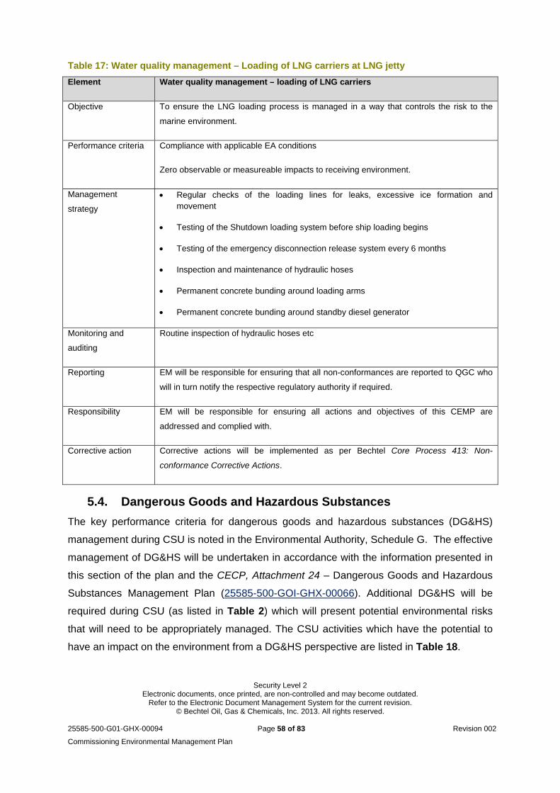
Security Level 2 Electronic documents, once printed, are non-controlled and may become outdated.
Refer to the Electronic Document Management System for the current revision. © Bechtel Oil, Gas & Chemicals, Inc. 2013. All rights reserved.
25585-500-G01-GHX-00094 Page 58 of 83 Revision 002
Commissioning Environmental Management Plan
Table 17: Water quality management – Loading of LNG carriers at LNG jetty
Element Water quality management – loading of LNG carriers
Objective To ensure the LNG loading process is managed in a way that controls the risk to the
marine environment.
Performance criteria Compliance with applicable EA conditions
Zero observable or measureable impacts to receiving environment.
Management
strategy
Regular checks of the loading lines for leaks, excessive ice formation and movement
Testing of the Shutdown loading system before ship loading begins
Testing of the emergency disconnection release system every 6 months
Inspection and maintenance of hydraulic hoses
Permanent concrete bunding around loading arms
Permanent concrete bunding around standby diesel generator
Monitoring and
auditing
Routine inspection of hydraulic hoses etc
Reporting EM will be responsible for ensuring that all non-conformances are reported to QGC who
will in turn notify the respective regulatory authority if required.
Responsibility EM will be responsible for ensuring all actions and objectives of this CEMP are
addressed and complied with.
Corrective action Corrective actions will be implemented as per Bechtel Core Process 413: Non-
conformance Corrective Actions.
5.4. Dangerous Goods and Hazardous Substances
The key performance criteria for dangerous goods and hazardous substances (DG&HS)
management during CSU is noted in the Environmental Authority, Schedule G. The effective
management of DG&HS will be undertaken in accordance with the information presented in
this section of the plan and the CECP, Attachment 24 – Dangerous Goods and Hazardous
Substances Management Plan (25585-500-GOI-GHX-00066). Additional DG&HS will be
required during CSU (as listed in Table 2) which will present potential environmental risks
that will need to be appropriately managed. The CSU activities which have the potential to
have an impact on the environment from a DG&HS perspective are listed in Table 18.
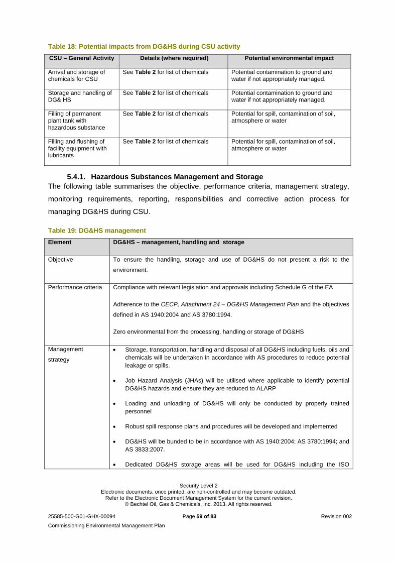
Security Level 2 Electronic documents, once printed, are non-controlled and may become outdated.
Refer to the Electronic Document Management System for the current revision. © Bechtel Oil, Gas & Chemicals, Inc. 2013. All rights reserved.
25585-500-G01-GHX-00094 Page 59 of 83 Revision 002
Commissioning Environmental Management Plan
Table 18: Potential impacts from DG&HS during CSU activity
CSU – General Activity Details (where required) Potential environmental impact
Arrival and storage of chemicals for CSU
See Table 2 for list of chemicals Potential contamination to ground and water if not appropriately managed.
Storage and handling of DG& HS
See Table 2 for list of chemicals Potential contamination to ground and water if not appropriately managed.
Filling of permanent plant tank with hazardous substance
See Table 2 for list of chemicals Potential for spill, contamination of soil, atmosphere or water
Filling and flushing of facility equipment with lubricants
See Table 2 for list of chemicals Potential for spill, contamination of soil, atmosphere or water
5.4.1. Hazardous Substances Management and Storage The following table summarises the objective, performance criteria, management strategy,
monitoring requirements, reporting, responsibilities and corrective action process for
managing DG&HS during CSU.
Table 19: DG&HS management
Element DG&HS – management, handling and storage
Objective To ensure the handling, storage and use of DG&HS do not present a risk to the
environment.
Performance criteria Compliance with relevant legislation and approvals including Schedule G of the EA
Adherence to the CECP, Attachment 24 – DG&HS Management Plan and the objectives
defined in AS 1940:2004 and AS 3780:1994.
Zero environmental from the processing, handling or storage of DG&HS
Management
strategy
Storage, transportation, handling and disposal of all DG&HS including fuels, oils and chemicals will be undertaken in accordance with AS procedures to reduce potential leakage or spills.
Job Hazard Analysis (JHAs) will be utilised where applicable to identify potential DG&HS hazards and ensure they are reduced to ALARP
Loading and unloading of DG&HS will only be conducted by properly trained personnel
Robust spill response plans and procedures will be developed and implemented
DG&HS will be bunded to be in accordance with AS 1940:2004; AS 3780:1994; and AS 3833:2007.
Dedicated DG&HS storage areas will be used for DG&HS including the ISO
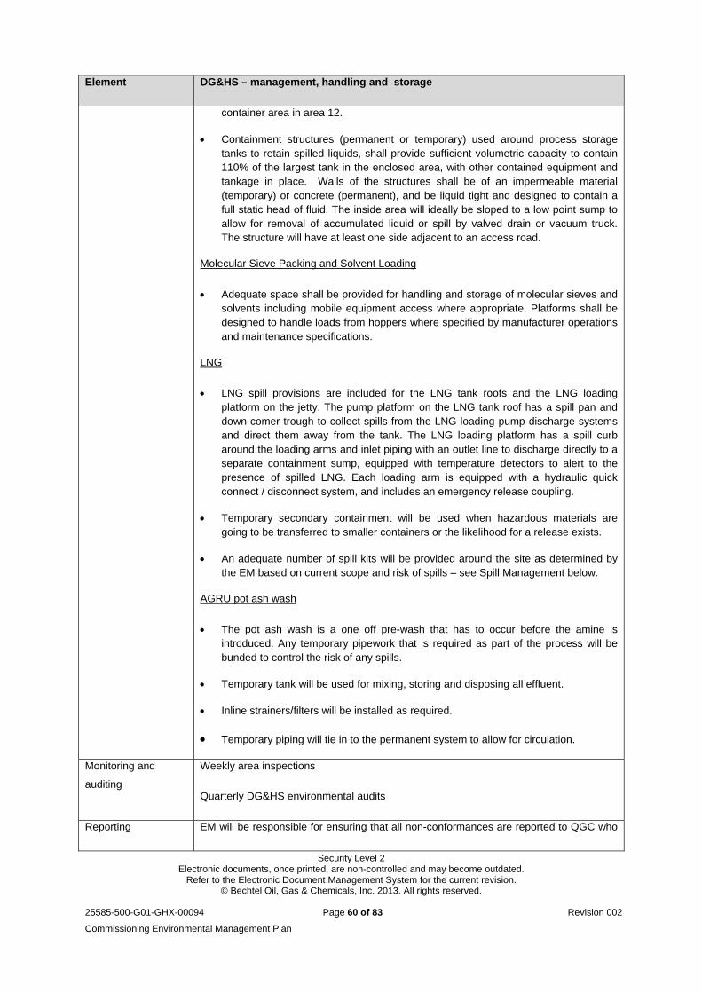
Security Level 2 Electronic documents, once printed, are non-controlled and may become outdated.
Refer to the Electronic Document Management System for the current revision. © Bechtel Oil, Gas & Chemicals, Inc. 2013. All rights reserved.
25585-500-G01-GHX-00094 Page 60 of 83 Revision 002
Commissioning Environmental Management Plan
Element DG&HS – management, handling and storage
container area in area 12.
Containment structures (permanent or temporary) used around process storage tanks to retain spilled liquids, shall provide sufficient volumetric capacity to contain 110% of the largest tank in the enclosed area, with other contained equipment and tankage in place. Walls of the structures shall be of an impermeable material (temporary) or concrete (permanent), and be liquid tight and designed to contain a full static head of fluid. The inside area will ideally be sloped to a low point sump to allow for removal of accumulated liquid or spill by valved drain or vacuum truck. The structure will have at least one side adjacent to an access road.
Molecular Sieve Packing and Solvent Loading
Adequate space shall be provided for handling and storage of molecular sieves and solvents including mobile equipment access where appropriate. Platforms shall be designed to handle loads from hoppers where specified by manufacturer operations and maintenance specifications.
LNG
LNG spill provisions are included for the LNG tank roofs and the LNG loading platform on the jetty. The pump platform on the LNG tank roof has a spill pan and down-comer trough to collect spills from the LNG loading pump discharge systems and direct them away from the tank. The LNG loading platform has a spill curb around the loading arms and inlet piping with an outlet line to discharge directly to a separate containment sump, equipped with temperature detectors to alert to the presence of spilled LNG. Each loading arm is equipped with a hydraulic quick connect / disconnect system, and includes an emergency release coupling.
Temporary secondary containment will be used when hazardous materials are going to be transferred to smaller containers or the likelihood for a release exists.
An adequate number of spill kits will be provided around the site as determined by the EM based on current scope and risk of spills – see Spill Management below.
AGRU pot ash wash
The pot ash wash is a one off pre-wash that has to occur before the amine is introduced. Any temporary pipework that is required as part of the process will be bunded to control the risk of any spills.
Temporary tank will be used for mixing, storing and disposing all effluent.
Inline strainers/filters will be installed as required.
Temporary piping will tie in to the permanent system to allow for circulation.
Monitoring and
auditing
Weekly area inspections
Quarterly DG&HS environmental audits
Reporting EM will be responsible for ensuring that all non-conformances are reported to QGC who
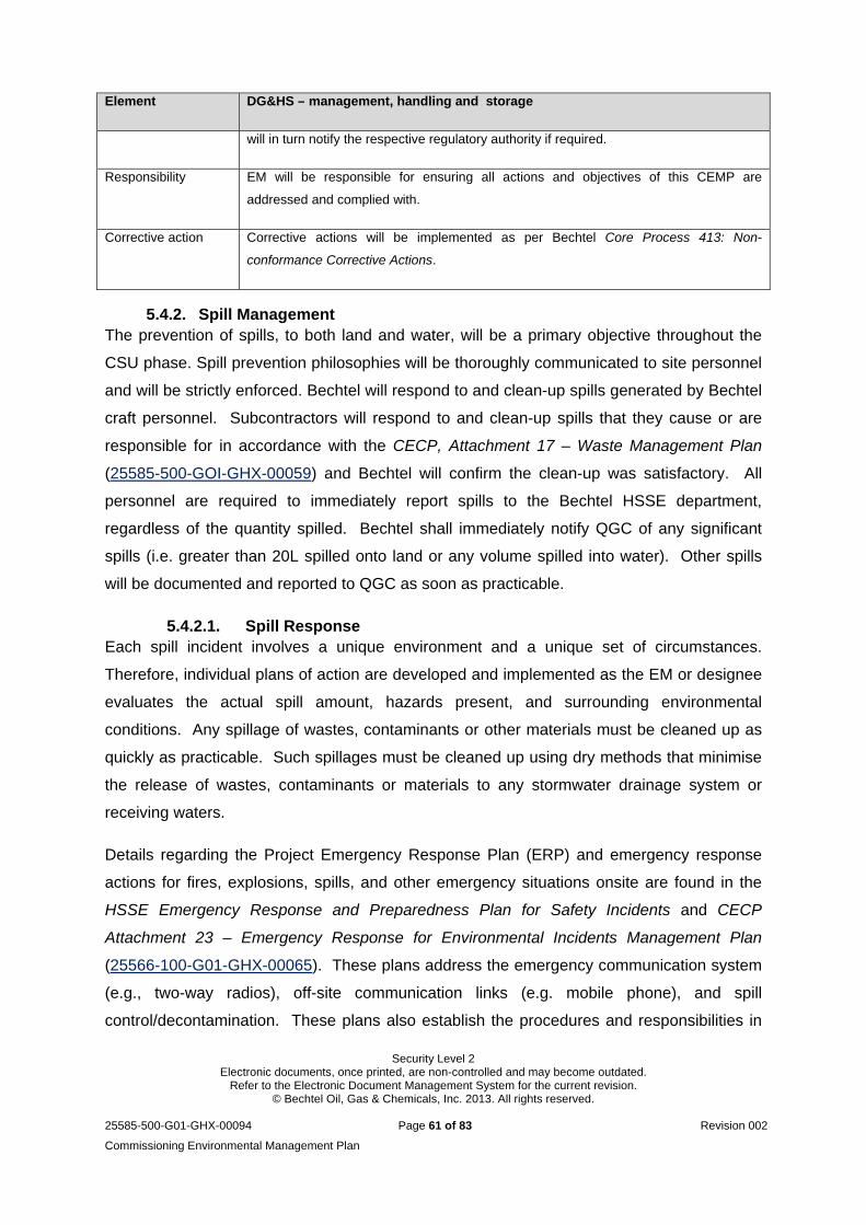
Security Level 2 Electronic documents, once printed, are non-controlled and may become outdated.
Refer to the Electronic Document Management System for the current revision. © Bechtel Oil, Gas & Chemicals, Inc. 2013. All rights reserved.
25585-500-G01-GHX-00094 Page 61 of 83 Revision 002
Commissioning Environmental Management Plan
Element DG&HS – management, handling and storage
will in turn notify the respective regulatory authority if required.
Responsibility EM will be responsible for ensuring all actions and objectives of this CEMP are
addressed and complied with.
Corrective action Corrective actions will be implemented as per Bechtel Core Process 413: Non-
conformance Corrective Actions.
5.4.2. Spill Management The prevention of spills, to both land and water, will be a primary objective throughout the
CSU phase. Spill prevention philosophies will be thoroughly communicated to site personnel
and will be strictly enforced. Bechtel will respond to and clean-up spills generated by Bechtel
craft personnel. Subcontractors will respond to and clean-up spills that they cause or are
responsible for in accordance with the CECP, Attachment 17 – Waste Management Plan
(25585-500-GOI-GHX-00059) and Bechtel will confirm the clean-up was satisfactory. All
personnel are required to immediately report spills to the Bechtel HSSE department,
regardless of the quantity spilled. Bechtel shall immediately notify QGC of any significant
spills (i.e. greater than 20L spilled onto land or any volume spilled into water). Other spills
will be documented and reported to QGC as soon as practicable.
5.4.2.1. Spill Response Each spill incident involves a unique environment and a unique set of circumstances.
Therefore, individual plans of action are developed and implemented as the EM or designee
evaluates the actual spill amount, hazards present, and surrounding environmental
conditions. Any spillage of wastes, contaminants or other materials must be cleaned up as
quickly as practicable. Such spillages must be cleaned up using dry methods that minimise
the release of wastes, contaminants or materials to any stormwater drainage system or
receiving waters.
Details regarding the Project Emergency Response Plan (ERP) and emergency response
actions for fires, explosions, spills, and other emergency situations onsite are found in the
HSSE Emergency Response and Preparedness Plan for Safety Incidents and CECP
Attachment 23 – Emergency Response for Environmental Incidents Management Plan
(25566-100-G01-GHX-00065). These plans address the emergency communication system
(e.g., two-way radios), off-site communication links (e.g. mobile phone), and spill
control/decontamination. These plans also establish the procedures and responsibilities in
Security Level 2 Electronic documents, once printed, are non-controlled and may become outdated.
Refer to the Electronic Document Management System for the current revision. © Bechtel Oil, Gas & Chemicals, Inc. 2013. All rights reserved.
25585-500-G01-GHX-00094 Page 62 of 83 Revision 002
Commissioning Environmental Management Plan
the event of an incident requiring emergency response. In addition, CECP Attachment 16 -
Phase III Marine Fuel and Oil Spill Prevention and Response Management Plan (25566-100-
G01-GHX-00084) details specific emergency procedures to be implemented in the case of
environmental incidents such as spills and contamination to both marine and land
environments.
5.4.2.2. Spill Cleanup Actions Bechtel and its Subcontractors are responsible for cleaning up spills they are responsible for,
to Bechtel’s satisfaction. Bechtel is responsible for cleaning up spills that Bechtel Direct
Hire personnel cause. Spills (regardless of quantity) will be documented in the
Environmental Incident Register. Spills greater than 20L (i.e. “significant”) and/or any spills
in environmentally sensitive areas (e.g. the marine environment) will be documented on an
Environmental Incident Report.
Upon discovering a spill, non-essential personnel will be immediately removed from the
impacted area. The EM will be notified of the spill immediately. Personnel discovering the
spill shall eliminate sources of ignition (e.g. radios, cell phones, lighters) from the immediate
spill area. If it is safe to do so, the source of the leak will be stopped and the spilled material
should be contained within as small an area as possible by installing bunds or absorbents.
In the event of rainfall, personnel will place plastic sheeting or other protection over the spill
(if possible), to prevent mixing or washing by storm water.
Upon arrival at the scene, the EM will secure the area and establish a perimeter at a safe
distance from the spill. The EM will analyse the situation and determine if it is safe to clean
up the spill. The EM will coordinate and direct any emergency response effort for large and
serious incidents. If a Subcontractor is responsible, the Subcontractor may coordinate the
cleanup if approved by the EM and the CM. Appropriate personnel and response equipment
will be mobilised and the spill will be cleaned up under the guidance of the EM.
Contaminated cleanup waste will be properly contained and transported to the site WMA to
be disposed of as regulated waste. The EM or the CM shall notify the Senior Project
Manager and the onsite QGC representative immediately after any significant spill.
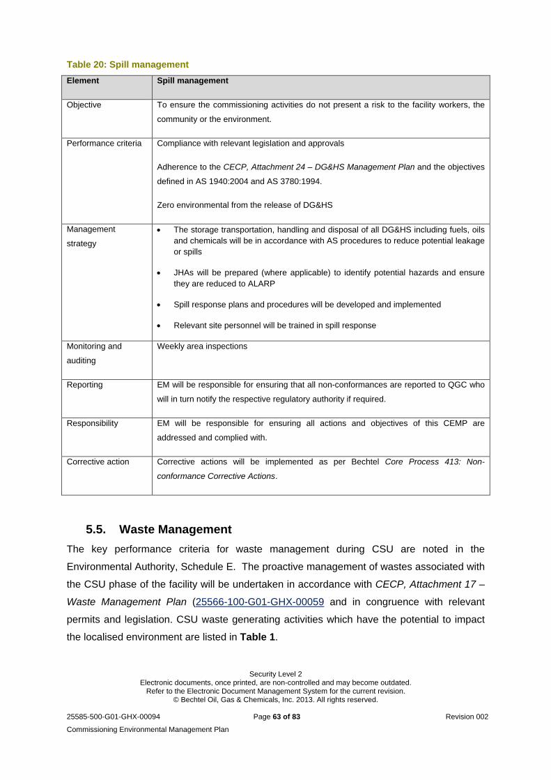
Security Level 2 Electronic documents, once printed, are non-controlled and may become outdated.
Refer to the Electronic Document Management System for the current revision. © Bechtel Oil, Gas & Chemicals, Inc. 2013. All rights reserved.
25585-500-G01-GHX-00094 Page 63 of 83 Revision 002
Commissioning Environmental Management Plan
Table 20: Spill management
Element Spill management
Objective To ensure the commissioning activities do not present a risk to the facility workers, the
community or the environment.
Performance criteria Compliance with relevant legislation and approvals
Adherence to the CECP, Attachment 24 – DG&HS Management Plan and the objectives
defined in AS 1940:2004 and AS 3780:1994.
Zero environmental from the release of DG&HS
Management
strategy
The storage transportation, handling and disposal of all DG&HS including fuels, oils and chemicals will be in accordance with AS procedures to reduce potential leakage or spills
JHAs will be prepared (where applicable) to identify potential hazards and ensure they are reduced to ALARP
Spill response plans and procedures will be developed and implemented
Relevant site personnel will be trained in spill response
Monitoring and
auditing
Weekly area inspections
Reporting EM will be responsible for ensuring that all non-conformances are reported to QGC who
will in turn notify the respective regulatory authority if required.
Responsibility EM will be responsible for ensuring all actions and objectives of this CEMP are
addressed and complied with.
Corrective action Corrective actions will be implemented as per Bechtel Core Process 413: Non-
conformance Corrective Actions.
5.5. Waste Management
The key performance criteria for waste management during CSU are noted in the
Environmental Authority, Schedule E. The proactive management of wastes associated with
the CSU phase of the facility will be undertaken in accordance with CECP, Attachment 17 –
Waste Management Plan (25566-100-G01-GHX-00059 and in congruence with relevant
permits and legislation. CSU waste generating activities which have the potential to impact
the localised environment are listed in Table 1.
Security Level 2 Electronic documents, once printed, are non-controlled and may become outdated.
Refer to the Electronic Document Management System for the current revision. © Bechtel Oil, Gas & Chemicals, Inc. 2013. All rights reserved.
25585-500-G01-GHX-00094 Page 64 of 83 Revision 002
Commissioning Environmental Management Plan
Bechtel is responsible for the overall management of waste for the QCLNG project until
TCCC to QGC. Until TCCC, Bechtel will continue to manage the handling and disposal of
wastes generated on site, under the arrangement implemented during the construction
phase of the project. Bechtel is committed to reducing waste production through the
implementation of the recovery, reuse and recycle philosophy, aiming to promote best
practice waste disposal methodologies. The following section details the collection,
handling, storage, transport, disposal and monitoring of site generated wastes throughout
the CSU phase.
5.5.1. Collection and Handling All wastes will be collected and segregated into their respective waste streams based on
their intended disposal option. Wastes will be stored on site and handled in accordance with
the Waste and Recycling Management Process Procedure (25585-500-GPP-GHX-10007)
and the EPP Waste. Bechtel has engaged a third party waste removal contractor
(Remondis) to facilitate the collection, transportation and disposal of all wastes generated
throughout the CSU phase of the QCLNG Project. This contractor is accredited for the
transportation and disposal of general and regulated wastes.
5.5.2. Storage and Handling All wastes will be stored and handled as detailed in the Waste and Recycling Management
Process Procedure (25585-500-GPP-GHX-10007). Waste storage areas will be clearly
marked and storage bins will be protected from environmental influences (e.g. wind, rain).
5.5.3. Transportation of Waste All wastes will be transported from Curtis Island to the mainland via barges used to deliver
materials and resources to the project site. Appropriate environmental mitigations will be
implemented to ensure minimal potential EH occurring. Those mitigation measures will be
assessed and documented through a job-specific Job Hazard Analysis assessment
conducted by the waste contractor.
5.5.4. Monitoring of Waste A project Waste Management Register (25566-100-ENV-REG-10005) has been established
for construction activities and will incorporate the recording and tracking of waste generated
from CSU activities. It covers differing types of waste streams (including trackable waste)
and includes the following details:
Type of waste
Volume
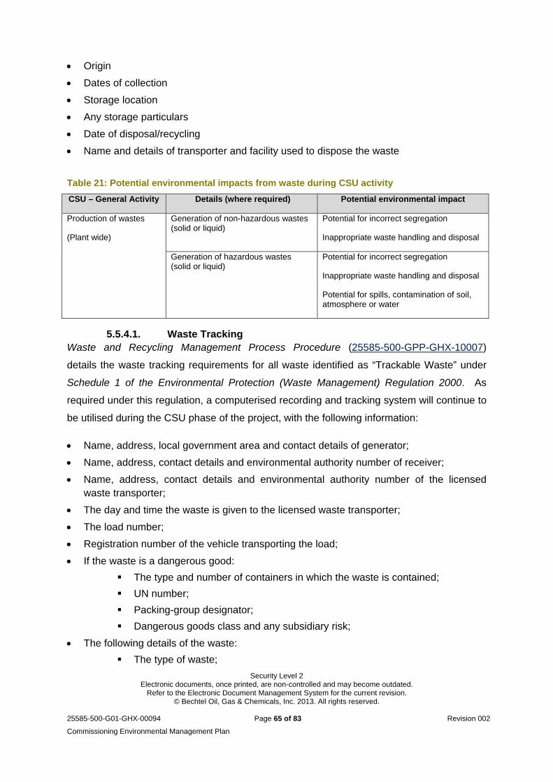
Security Level 2 Electronic documents, once printed, are non-controlled and may become outdated.
Refer to the Electronic Document Management System for the current revision. © Bechtel Oil, Gas & Chemicals, Inc. 2013. All rights reserved.
25585-500-G01-GHX-00094 Page 65 of 83 Revision 002
Commissioning Environmental Management Plan
Origin
Dates of collection
Storage location
Any storage particulars
Date of disposal/recycling
Name and details of transporter and facility used to dispose the waste
Table 21: Potential environmental impacts from waste during CSU activity
CSU – General Activity Details (where required) Potential environmental impact
Production of wastes
(Plant wide)
Generation of non-hazardous wastes (solid or liquid)
Potential for incorrect segregation
Inappropriate waste handling and disposal
Generation of hazardous wastes (solid or liquid)
Potential for incorrect segregation
Inappropriate waste handling and disposal
Potential for spills, contamination of soil, atmosphere or water
5.5.4.1. Waste Tracking Waste and Recycling Management Process Procedure (25585-500-GPP-GHX-10007)
details the waste tracking requirements for all waste identified as “Trackable Waste” under
Schedule 1 of the Environmental Protection (Waste Management) Regulation 2000. As
required under this regulation, a computerised recording and tracking system will continue to
be utilised during the CSU phase of the project, with the following information:
Name, address, local government area and contact details of generator;
Name, address, contact details and environmental authority number of receiver;
Name, address, contact details and environmental authority number of the licensed waste transporter;
The day and time the waste is given to the licensed waste transporter;
The load number;
Registration number of the vehicle transporting the load;
If the waste is a dangerous good:
The type and number of containers in which the waste is contained;
UN number;
Packing-group designator;
Dangerous goods class and any subsidiary risk;
The following details of the waste:
The type of waste;
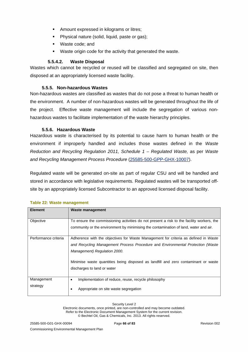
Security Level 2 Electronic documents, once printed, are non-controlled and may become outdated.
Refer to the Electronic Document Management System for the current revision. © Bechtel Oil, Gas & Chemicals, Inc. 2013. All rights reserved.
25585-500-G01-GHX-00094 Page 66 of 83 Revision 002
Commissioning Environmental Management Plan
Amount expressed in kilograms or litres;
Physical nature (solid, liquid, paste or gas);
Waste code; and
Waste origin code for the activity that generated the waste.
5.5.4.2. Waste Disposal Wastes which cannot be recycled or reused will be classified and segregated on site, then
disposed at an appropriately licensed waste facility.
5.5.5. Non-hazardous Wastes Non-hazardous wastes are classified as wastes that do not pose a threat to human health or
the environment. A number of non-hazardous wastes will be generated throughout the life of
the project. Effective waste management will include the segregation of various non-
hazardous wastes to facilitate implementation of the waste hierarchy principles.
5.5.6. Hazardous Waste Hazardous waste is characterised by its potential to cause harm to human health or the
environment if improperly handled and includes those wastes defined in the Waste
Reduction and Recycling Regulation 2011, Schedule 1 – Regulated Waste, as per Waste
and Recycling Management Process Procedure (25585-500-GPP-GHX-10007).
Regulated waste will be generated on-site as part of regular CSU and will be handled and
stored in accordance with legislative requirements. Regulated wastes will be transported off-
site by an appropriately licensed Subcontractor to an approved licensed disposal facility.
Table 22: Waste management
Element Waste management
Objective To ensure the commissioning activities do not present a risk to the facility workers, the
community or the environment by minimising the contamination of land, water and air.
Performance criteria Adherence with the objectives for Waste Management for criteria as defined in Waste
and Recycling Management Process Procedure and Environmental Protection (Waste
Management) Regulation 2000.
Minimise waste quantities being disposed as landfill and zero contaminant or waste
discharges to land or water
Management
strategy
Implementation of reduce, reuse, recycle philosophy
Appropriate on site waste segregation
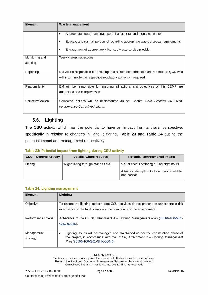
Security Level 2 Electronic documents, once printed, are non-controlled and may become outdated.
Refer to the Electronic Document Management System for the current revision. © Bechtel Oil, Gas & Chemicals, Inc. 2013. All rights reserved.
25585-500-G01-GHX-00094 Page 67 of 83 Revision 002
Commissioning Environmental Management Plan
Element Waste management
Appropriate storage and transport of all general and regulated waste
Educate and train all personnel regarding appropriate waste disposal requirements
Engagement of appropriately licensed waste service provider
Monitoring and
auditing
Weekly area inspections.
Reporting EM will be responsible for ensuring that all non-conformances are reported to QGC who
will in turn notify the respective regulatory authority if required.
Responsibility EM will be responsible for ensuring all actions and objectives of this CEMP are
addressed and complied with.
Corrective action Corrective actions will be implemented as per Bechtel Core Process 413: Non-
conformance Corrective Actions.
5.6. Lighting
The CSU activity which has the potential to have an impact from a visual perspective,
specifically in relation to changes in light, is flaring. Table 23 and Table 24 outline the
potential impact and management respectively.
Table 23: Potential impact from lighting during CSU activity
CSU – General Activity Details (where required) Potential environmental impact
Flaring Night flaring through marine flare
Visual effects of flaring during night hours
Attraction/disruption to local marine wildlife and habitat
Table 24: Lighting management
Element Lighting
Objective To ensure the lighting impacts from CSU activities do not present an unacceptable risk
or nuisance to the facility workers, the community or the environment.
Performance criteria Adherence to the CECP, Attachment 4 – Lighting Management Plan (25566-100-G01-
GHX-00046).
Management
strategy
Lighting issues will be managed and maintained as per the construction phase of the project, in accordance with the CECP, Attachment 4 – Lighting Management Plan (25566-100-G01-GHX-00046).
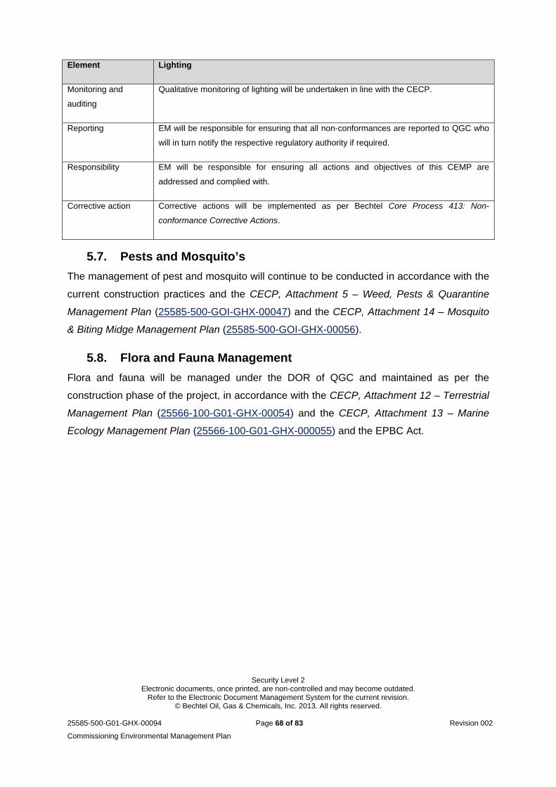
Security Level 2 Electronic documents, once printed, are non-controlled and may become outdated.
Refer to the Electronic Document Management System for the current revision. © Bechtel Oil, Gas & Chemicals, Inc. 2013. All rights reserved.
25585-500-G01-GHX-00094 Page 68 of 83 Revision 002
Commissioning Environmental Management Plan
Element Lighting
Monitoring and
auditing
Qualitative monitoring of lighting will be undertaken in line with the CECP.
Reporting EM will be responsible for ensuring that all non-conformances are reported to QGC who
will in turn notify the respective regulatory authority if required.
Responsibility EM will be responsible for ensuring all actions and objectives of this CEMP are
addressed and complied with.
Corrective action Corrective actions will be implemented as per Bechtel Core Process 413: Non-
conformance Corrective Actions.
5.7. Pests and Mosquito’s
The management of pest and mosquito will continue to be conducted in accordance with the
current construction practices and the CECP, Attachment 5 – Weed, Pests & Quarantine
Management Plan (25585-500-GOI-GHX-00047) and the CECP, Attachment 14 – Mosquito
& Biting Midge Management Plan (25585-500-GOI-GHX-00056).
5.8. Flora and Fauna Management
Flora and fauna will be managed under the DOR of QGC and maintained as per the
construction phase of the project, in accordance with the CECP, Attachment 12 – Terrestrial
Management Plan (25566-100-G01-GHX-00054) and the CECP, Attachment 13 – Marine
Ecology Management Plan (25566-100-G01-GHX-000055) and the EPBC Act.
Security Level 2 Electronic documents, once printed, are non-controlled and may become outdated.
Refer to the Electronic Document Management System for the current revision. © Bechtel Oil, Gas & Chemicals, Inc. 2013. All rights reserved.
25585-500-G01-GHX-00094 Page 69 of 83 Revision 002
Commissioning Environmental Management Plan
6. General Environmental Management
6.1. Environmental Emergency Preparedness
Environmental emergency preparedness includes the development and implementation of
response procedures for possible emergencies, emergency response materials (e.g. spill
kits, firefighting tools), and the training of adequate numbers of onsite emergency
responders.
Bechtel’s Core Process 410: Emergency Environmental Preparedness and associated
HSSE policies and procedures describe the preparedness measures and response that will
be conducted in the event of an emergency. Environmental emergencies may involve spills
of dangerous goods on land or water, unanticipated discovery of hazardous materials,
wildfire, unauthorised discharge of storm water or other contaminated water, unauthorised
release of air pollutants, and unexpected encounters with wildlife. Response to an
emergency generally follows these steps:
Stop the source of the problem if it is safe to do so
Contain the problem to the extent possible
Report the problem
Clean up and remediate the affected resources.
6.2. Integrated Control and Safety System
In addition to unanticipated emergency response, the Integrated Control and Safety System
(ICSS) will assist with minimising incident releases or environmental incidents. The ICSS
primarily consists of the basic process control system; safety instrumented system (including
process shutdown and safety shutdown system); fire and gas systems; intelligent field
instrumentation and associated networks.
The degree of automation for each unit within the processing plant will allow for operators to
access all process information and controls through a distributed control system, allowing
the CSU team to maintain safe and reliable control of all plant equipment. The plant’s alarm
philosophy will assist with directing personnel’s attention to the system which requires
immediate attention to prevent hazardous situations from developing and/or minimise
harmful impact to the product, equipment or personnel.
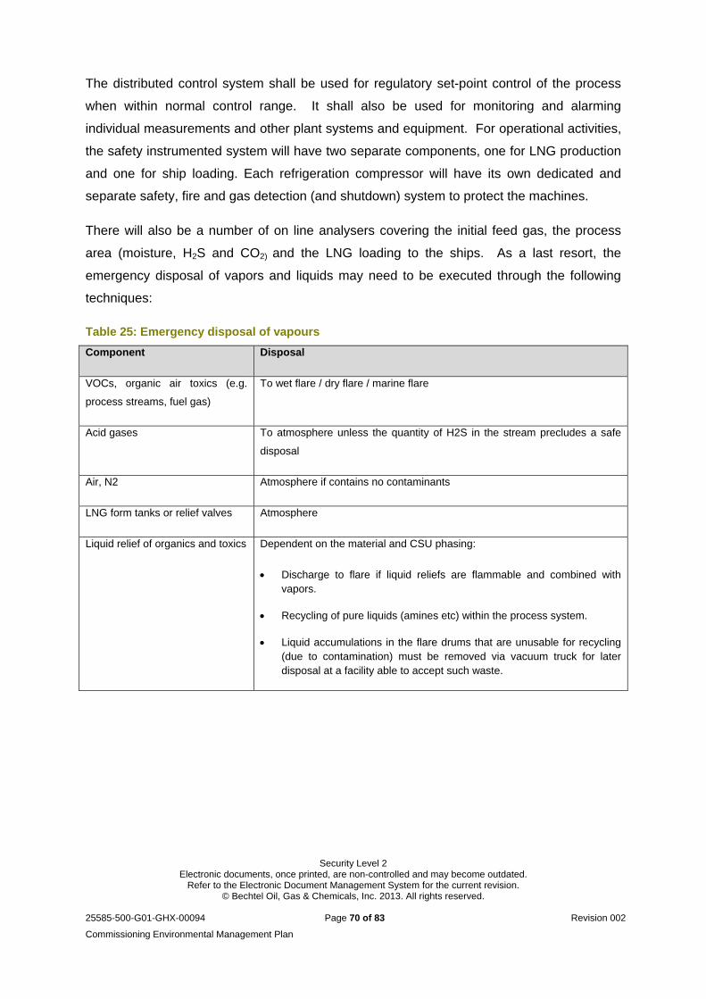
Security Level 2 Electronic documents, once printed, are non-controlled and may become outdated.
Refer to the Electronic Document Management System for the current revision. © Bechtel Oil, Gas & Chemicals, Inc. 2013. All rights reserved.
25585-500-G01-GHX-00094 Page 70 of 83 Revision 002
Commissioning Environmental Management Plan
The distributed control system shall be used for regulatory set-point control of the process
when within normal control range. It shall also be used for monitoring and alarming
individual measurements and other plant systems and equipment. For operational activities,
the safety instrumented system will have two separate components, one for LNG production
and one for ship loading. Each refrigeration compressor will have its own dedicated and
separate safety, fire and gas detection (and shutdown) system to protect the machines.
There will also be a number of on line analysers covering the initial feed gas, the process
area (moisture, H2S and CO2) and the LNG loading to the ships. As a last resort, the
emergency disposal of vapors and liquids may need to be executed through the following
techniques:
Table 25: Emergency disposal of vapours
Component Disposal
VOCs, organic air toxics (e.g.
process streams, fuel gas)
To wet flare / dry flare / marine flare
Acid gases To atmosphere unless the quantity of H2S in the stream precludes a safe
disposal
Air, N2 Atmosphere if contains no contaminants
LNG form tanks or relief valves Atmosphere
Liquid relief of organics and toxics Dependent on the material and CSU phasing:
Discharge to flare if liquid reliefs are flammable and combined with vapors.
Recycling of pure liquids (amines etc) within the process system.
Liquid accumulations in the flare drums that are unusable for recycling (due to contamination) must be removed via vacuum truck for later disposal at a facility able to accept such waste.
Security Level 2 Electronic documents, once printed, are non-controlled and may become outdated.
Refer to the Electronic Document Management System for the current revision. © Bechtel Oil, Gas & Chemicals, Inc. 2013. All rights reserved.
25585-500-G01-GHX-00094 Page 71 of 83 Revision 002
Commissioning Environmental Management Plan
6.3. Environmental Incidents
An environmental incident will be regarded as any incident that has the potential to cause
harm to the environment. In the event that an environmental incident occurs, the following
steps will be followed immediately:
Prevent further pollution/environmental harm (including impacts on air, water quality, flora and fauna and noise environment);
Clean-up and/or control polluting substance(s);
Implement mitigation measures to prevent recurrence of a similar incident; and
Document the incident and instigate an incident investigation as appropriate.
Incidents will be reported within twenty-four (24) hours to the relevant Environmental
Manager. Incidents likely to cause off-site impacts or significant environmental harm will be
reported by QGC to relevant agencies as soon as practicable (within 24 hours) after
becoming aware of the incident, in accordance with statutory requirements. The notification
of emergencies or incidents will include the following:
The EA number and name of holder
The name and telephone number of the designated contact person
The location of the emergency or incident
The date and time of the release
The time the holder of the authority became aware of the emergency or incident
The estimated quantity and type of any substance involved in the incident
The actual or potential cause of the release
A description of the effects of the incident including the environmental harm caused, threatened, or suspected to be caused by the release
Any sampling conducted or proposed, relevant to the emergency or incident
Actions taken to prevent further release and mitigate any environmental harm caused by the release/mismanagement incident
Within fourteen (14) days following the initial notification of an emergency or incident or
receipt of monitoring results, further written advice must be provided, including:
Results and interpretation of any samples taken and analysed;
Outcomes of actions taken at the time to prevent or minimise environmental harm; and
Proposed actions to prevent a recurrence of the emergency or incident
Security Level 2 Electronic documents, once printed, are non-controlled and may become outdated.
Refer to the Electronic Document Management System for the current revision. © Bechtel Oil, Gas & Chemicals, Inc. 2013. All rights reserved.
25585-500-G01-GHX-00094 Page 72 of 83 Revision 002
Commissioning Environmental Management Plan
6.4. Job Hazard Analysis
A Job Hazard Analysis (JHA) will be undertaken to help personnel identify, analyse and
manage the hazards associated with their work. The JHA will formalise the process of
hazard identification and management that most people follow when working. The JHA will
require personnel to examine the task they are about to undertake by:
Breaking the job into separate, defined steps.
Identifying the potential hazards (safety and environmental) that could occur during each defined step.
Listing the method to be followed to prevent or limit the risk of injury, loss, damage or environmental incident that may be caused by each potential hazard.
6.4.1. Site Environmental Plan Site Environmental Plans (SEPs) are area specific management plans with the intent of
identifying the inherent risk associated with the work activities required for the construction
and operation of the plant. Particular attention is given to environmental aspects of concern
previously identified within the project footprint; e.g. ASS, Erosion and Sediment Control and
Water Quality.
Guidelines for the creation and implementation of SEPs have been developed to ensure
consistency and continuity throughout all areas. Details regarding the creation procedure
and the content of an SEP can be found in the Guidelines for Developing SEPs process
procedure (25585-500-GPP-GHX-10025) and the Environmental Hazard and Risk
Management process procedure (25585-500-GPP-GHX-10016).
6.5. Structure and Responsibilities
Relevant to this process procedure, each person undertaking an activity on the QCLNG
project is responsible for conforming to applicable Australian and Queensland laws and
regulations. Furthermore, all personnel are responsible for the environmental performance of
the activity and for complying with the general environmental duty (GED) as set out in
Section 319 of the EP Act, which states:
“A person must not carry out any activity that causes, or is likely to cause,
environmental harm unless the person takes all reasonable and practicable
measures to minimise the harm.”
There is also a requirement to conducting the work in accordance with permit requirements
and Bechtel Core Process 405: Resources, Roles and Responsibilities.
Security Level 2 Electronic documents, once printed, are non-controlled and may become outdated.
Refer to the Electronic Document Management System for the current revision. © Bechtel Oil, Gas & Chemicals, Inc. 2013. All rights reserved.
25585-500-G01-GHX-00094 Page 73 of 83 Revision 002
Commissioning Environmental Management Plan
6.5.1. Queensland Gas Company (QGC) As the owner and operator of the QCLNG project, QGC’s environmental responsibilities
include, but are not limited to:
Primary liaison with Australian Government authorities for the project;
Public and agency complaints;
When the administering authority advises QGC of a complaint alleging environmental nuisance, QGC must investigate the complaint and advise the administering authority in writing of the action undertaken or proposed;
When requested by the administering authority, QGC (or designated agent) must undertake monitoring (specified by the authority), within a reasonable and practicable timeframe (nominated by the authority), to investigate any complaint of EH at any sensitive or commercial place. The results of the investigation (including an analysis and interpretation of the monitoring results) and abatement measures implemented must be provided to the administering authority within fourteen (14) days of completion of the investigation, or receipt of monitoring results, whichever is the latter, and details of :
Proposed actions to prevent a recurrence of the emergency or incident
Outcomes of actions taken at the time to prevent or minimise EH/nuisance.
QGC to maintain a record of complaints and incidents causing EH, and actions taken in response to the complaint or incident, and retain the record of complaints required by this condition for five (5) years;
QGC must record the details, as identified in Section 9.2 of the CECP, for all complaints received and provide this information to the administering authority on request;
Submitting environmental permit applications and negotiating with relevant government agencies on permits and approvals as required;
Undertaking reporting requirements to the regulatory authority throughout the project; and
QGC will continue to work closely with indigenous communities so that cultural sensitivities relating to the project are duly considered and managed.
6.5.2. Bechtel As the Primary Contractor for the Engineering, Procurement, and Construction (EPC) scope
of work associated with the QCLNG facility, Bechtel is responsible for complying with its
obligations set forth in the Contract, permit requirements and management commitments.
Bechtel and its subcontractors are responsible for the implementation of this CEMP.
Described below are the specific responsibilities within the Bechtel project team for
maintaining environmental compliance during construction of the project.
Security Level 2 Electronic documents, once printed, are non-controlled and may become outdated.
Refer to the Electronic Document Management System for the current revision. © Bechtel Oil, Gas & Chemicals, Inc. 2013. All rights reserved.
25585-500-G01-GHX-00094 Page 74 of 83 Revision 002
Commissioning Environmental Management Plan
6.5.2.1. Senior Project Manager The Senior Project Manager (SPM) is the Bechtel representative with overall management
responsibility for compliance with project’s environmental requirements related to Bechtel’s
scope of work. The SPM will be assisted as required by a Site Manager and HSSE non-
manual personnel.
6.5.2.2. Site Manager The Site Manager (SM) is the Bechtel representative responsible for overall construction
management of the site as well as the site compliance with all applicable environmental
requirements. The SM oversees implementation of the requirements set forth in this process
procedure, including:
Communication to project personnel regarding the environmental compliance requirements and other items of environmental importance;
Coordination with the Site HSSE Manager and the Environmental Services Manager to implement the overall environmental control programme;
Immediate contact with the Senior Project Manager if significant matters pertaining to environmental compliance arise, in support of Bechtel Legal Instruction 127;
Undertake monitoring where required under the Contract to comply with the conditions of approval; and
Communicate any work stoppages to the QGC site representative.
6.5.2.3. Health, Safety, Security and Environmental Manager Bechtel Health, Safety, Security & Environmental Manager (HSSE Manager) is responsible
for and/or will oversee the following activities:
Direct complaints to QGC Public Relations specialists as required; and
Review complaints and assess or direct response, corrective actions undertaken or other recommendations or modifications to practices and closed out.
6.5.2.4. Environmental Services Manager Prior to and during the undertaking of Commissioning, the Bechtel Environmental Services
Manager (EM) is responsible for and/or will oversee the following activities:
Implement and update this management plan in coordination with Bechtel’s construction team;
Review construction and commissioning work plans and activities to advise and determine that appropriate environmental controls are incorporated;
Coordinate environmental inspections and water quality monitoring to ensure commitments under this management plan are engaged;
Security Level 2 Electronic documents, once printed, are non-controlled and may become outdated.
Refer to the Electronic Document Management System for the current revision. © Bechtel Oil, Gas & Chemicals, Inc. 2013. All rights reserved.
25585-500-G01-GHX-00094 Page 75 of 83 Revision 002
Commissioning Environmental Management Plan
Conduct environmental compliance evaluation of the analytical results relevant the water quality monitoring, and provide conditions of discharge (or contingency) based on the comparison to background and trigger values.
Auditing the system to confirm that activities are carried out is in line with the defined requirements and is producing the required outcomes.
Support the project team by providing guidance relating to environmental compliance issues and regulatory compliance support;
Coordinate with regulatory agencies after consultation with QGC;
Notify QGC and regulatory authority, if applicable, of environmental incidents and maintain a record of events relating to the incident and remedial action taken; and
Notify QGC of any activities or site changes that may require GCLNG to apply for new or amended environmental permits.
6.5.2.5. Environmental Inspectors Under the direction of the EM, the Environmental Inspectors (EIs) will directly support the
construction and commissioning team with all aspects of the commissioning phase,
including:
Raising awareness of potential environmental impacts with project personnel;
Directly notifying the EM and SM of any circumstances that warrant agency notification or management action in support of effective environmental compliance;
Monitor field commissioning activities which are planned and conducted in accordance with applicable environmental regulations and activity-specific requirements;
Participating in HSSE coordination meetings with project staff and QGC;
Participating in Commissioning coordination meetings;
When appropriate, participate in Government agency and authority meetings to review environmental requirements and compliance;
Conducting field inspection of commissioning activities for compliance with permit conditions and applicable environmental regulations;
Providing guidance to construction and commissioning teams for resolution of environmental compliance issues;
Conduct Environmental Training for personnel in relation to the undertaking of this activity, and provide guidance to facilitate compliance, communication and awareness.
Provide technical assistance and support to the Site Manager as required.
Security Level 2 Electronic documents, once printed, are non-controlled and may become outdated.
Refer to the Electronic Document Management System for the current revision. © Bechtel Oil, Gas & Chemicals, Inc. 2013. All rights reserved.
25585-500-G01-GHX-00094 Page 76 of 83 Revision 002
Commissioning Environmental Management Plan
7. Programmes and Procedures
The implementation and application of various HSSE programmes, including recycling, water
monitoring, and safety improvements and self-audit programmes are consistent with the
QCLNG HSSE Management System (HSSEMS). Thorough procedures for which measures
of performance and compliance can be applied and audited are highlighted in the HSSEMS
in accordance with Bechtel’s Core Process 411: Monitoring and Measurement.
Detailed procedures will be developed and reviewed as required for commissioning and
operation throughout the project lifetime, in accordance to the CECP, the EA and the
HSSEMS Asset and Operational Integrity.
7.1. Awareness, Training and Competency
Project personnel will receive training specific to the undertaking of commissioning activity,
in order to familiarise them with the relevant management systems and requirements, as
appropriate to their roles and responsibilities. Attendance records for personnel
induction/training will be maintained by the project. The environmental management training
will address:
The role of this CEMP;
Personnel responsibilities;
Incident and emergency response;
Health and safety instruction;
Identification and understanding of the environmental issues outlined in this CEMP;
Specific topics as applicable to the individual’s role.
7.2. Communications
All communications will be conducted in accordance to the Bechtel Core Process 407:
Communication, with consideration of Exhibit D of the Prime contract.
Security Level 2 Electronic documents, once printed, are non-controlled and may become outdated.
Refer to the Electronic Document Management System for the current revision. © Bechtel Oil, Gas & Chemicals, Inc. 2013. All rights reserved.
25585-500-G01-GHX-00094 Page 77 of 83 Revision 002
Commissioning Environmental Management Plan
8. Environmental Procedures and Forms
Environmental procedures and forms have been prepared for implementation during the
commissioning and operational activities to address risk and compliance management
systems. The management tools that are applicable include:
Procedures – provide instruction for specific environmental tasks for consistency in
approach and quality of results. Environmental procedures are developed for
managing issues including water monitoring and contamination testing, and are
linked to the Work Method Statements (WMS). A SEP will be developed, reviewed
and revised to display the required environmental mitigation measures adopted in
conjunction with the facilities environmental risk assessment.
Forms – including inspection reports, corrective action reports and audit reports.
8.1. Environmental Inspection
Environmental inspections will be performed and documented to verify that all environmental
requirements specified in this CEMP are being implemented and complied with during CSU
activities. The inspection schedule will be dictated by the type of activities occurring and the
environmental requirements relevant to those activities.
The environmental inspection checklists will include details of observations, the responsible
party, and when the situation will be mitigated. Example checklists are included within the
Environmental Monitoring Programme. The EM, or designee, will implement required
environmental improvements and maintain a database that will identify the status of
corrective actions. Open actions will be reviewed in the weekly progress meeting to help
promote timely closeout.
If necessary, “stop work” orders will be issued if activities are not in accordance with the
applicable environmental requirements, which may result in a significant adverse impact to
the environment if the activity continues. If such conditions exist, the EM, or designee, will
take appropriate action to halt and correct the problem and immediately notify the SM, and
other personnel, as appropriate. The construction activity in question will not resume until
corrective actions have been taken. Inspections records and audit reports will be available
for review by the relevant administering authority upon request.
Security Level 2 Electronic documents, once printed, are non-controlled and may become outdated.
Refer to the Electronic Document Management System for the current revision. © Bechtel Oil, Gas & Chemicals, Inc. 2013. All rights reserved.
25585-500-G01-GHX-00094 Page 78 of 83 Revision 002
Commissioning Environmental Management Plan
8.2. Environmental Auditing
Auditing of the CEMP and CSU activities will be undertaken in accordance with the Internal
Auditing Process Procedure (25585-500-GPP-GHX-10027) and Bechtel Core Process 415:
Internal Audit for Environmental Management. This will be done to confirm that activities are
carried out in line with permit requirements, and are achieving the desired environmental
outcomes. These audits will be initiated by the Environmental Services Manager and
performed by an internal or external auditor. An audit protocol would include the following:
Review the scope, plan, and schedule of the audit;
Examine objective evidence to verify conformance with the CEMP and other associated
environmental management plan or procedural requirements;
Give specific attention to continual improvement actions developed in response to
previous audit findings;
Post-audit communication to present audit findings, clarify any misunderstandings and
summarise the audit findings;
Review audit programme annually and revise to reflect any improvements to the
methodology, auditors or timeframe of audits;
Complete an Audit Summary Report and have results discussed at the next
management meeting; and
List in the Audit Summary Report any continual improvement actions required to prevent
reoccurrence of any identified issues or to maximise opportunities for improvement.
8.3. Non-conformity, Investigation and Preventive Action
Through the use of inspections, internal auditing processes, complaints and incidents, actual
non-conformances and corrective actions will be identified. All non-conformances will be
recorded, assessed for significant risk and have corrective actions established as per
Bechtel Core Process 413: Non-conformance Corrective Actions. To ensure adequate
response, all non-conformances will be tracked through as preventative actions to minimise
the recurrence and to improve performance.
8.4. Document Control and Records
The system used for control of management and technical documents including “controlled”
documents subject to revision will enable the complete management of all documents,
including the identification of document or drawing lists, author and recipient management,
Security Level 2 Electronic documents, once printed, are non-controlled and may become outdated.
Refer to the Electronic Document Management System for the current revision. © Bechtel Oil, Gas & Chemicals, Inc. 2013. All rights reserved.
25585-500-G01-GHX-00094 Page 79 of 83 Revision 002
Commissioning Environmental Management Plan
and various forms of reporting. All documents and records are controlled in accordance with
Bechtel Core Process 408: Documentation and Control of Documents.
8.5. Continual Improvement
To ensure the continued suitability and effectiveness of the CEMP and all other associated
management plans, a regular review and update of the environmental management
programme is to be undertaken, as per Bechtel Core Process 416: Management Review and
the Environmental Review and the QCLNG Continuous Improvement Process Procedure
(25585-500-GPP-GHX-10023).
8.6. Review
This CEMP, its functionality, implementation, and the associated elements of the
accompanying management systems, will be reviewed periodically for conformance with
project objectives, legal and other requirements. A review may also be undertaken following
request by the administering authority. The outcomes of the management review process
will be incorporated as improvements to this CEMP, associated management plans and
other plans and procedures, to facilitate regulatory and policy compliance and continuous
improvement.
Security Level 2 Electronic documents, once printed, are non-controlled and may become outdated.
Refer to the Electronic Document Management System for the current revision. © Bechtel Oil, Gas & Chemicals, Inc. 2013. All rights reserved.
25585-500-G01-GHX-00094 Page 80 of 83 Revision 002
Commissioning Environmental Management Plan
APPENDIX A - Legislation, Industry Standards and Guidelines
Commonwealth Legislation
Environment Protection and Biodiversity Conservation Act 1999
National Greenhouse and Emissions Reporting Act 2007
Clean Air Act 2012
Queensland Legislation
Coastal Protection and Management Act 1995
Dangerous Goods Safety Management Act 2001
Dangerous Goods Safety Management Regulation 2001
Environmental Protection Act 1994
Environmental Protection Regulation 2008
Environmental Protection (Noise) Policy 2008
Environmental Protection (Air) Policy 2008
Environmental Protection (Water) Policy 2009
Environmental Protection (Waste Management) Regulation 2000
Petroleum and Gas (Production and Safety) Act 2004
Project-relevant approvals, processes & documentation
Environmental Authority (DEHP Permit Number: EPP00711513)
Prescribed Tidal Works OPW – LNG Jetty (GRC DA Number: 479/2011)
Prescribed Tidal Works OPW – Tidal Area Infrastructure (GRC DA Number:
239/2010)
Air
AS 3580 Methods for Sampling and Analysis of Ambient Air
AS 4323.1 – 1995 Stationary source emissions, Method 1: Selection of sampling
positions’
Queensland EPA Air Quality Sampling Manual, 1997, EPA
Soil and contamination
Best Practice Erosion and Sediment Control, 2008 IECA
Security Level 2 Electronic documents, once printed, are non-controlled and may become outdated.
Refer to the Electronic Document Management System for the current revision. © Bechtel Oil, Gas & Chemicals, Inc. 2013. All rights reserved.
25585-500-G01-GHX-00094 Page 81 of 83 Revision 002
Commissioning Environmental Management Plan
“Draft Guidelines for the Assessment and Management of Contaminated Land in
Queensland, 1998, EPA
Dangerous Goods
AS 1940 Storage and Handling of Flammable and Combustible Liquids
AS 2809 Road Tank Vehicles for Dangerous Goods
AS 2931 Selection and Use of Emergency Procedure Guides for Transport of
Dangerous Goods.
AS 3780 The Storage and Handling of Corrosive Substances
AS 3833:2007 Storage and Handling of Mixed Classes of Dangerous Goods, in
Packages and Intermediate Bulk Containers
MARPOL Annexes I, II, IV and V
Standard for Marine Construction Activities within Gladstone Harbour (MSQ)
Noise
Queensland EPA Noise Management Manual (3rd Edition), 2000, EPA – check for
revision
Waste
Code of environmental compliance for certain aspects of regulated waste transport—
Version 2
Water
AS 2031 Selection of Containers and Preservation of Water Samples for Chemical
and Microbiological Analysis
ISO 5667-10:1992 Water Quality - Sampling - Part 10: Guidance on Sampling of
Waste Waters
Queensland Water Quality Guidelines, (Version 3) 2009, DERM
Security Level 2 Electronic documents, once printed, are non-controlled and may become outdated.
Refer to the Electronic Document Management System for the current revision. © Bechtel Oil, Gas & Chemicals, Inc. 2013. All rights reserved.
25585-500-G01-GHX-00094 Page 82 of 83 Revision 002
Commissioning Environmental Management Plan
APPENDIX B - Environmental Policies
QGC HSSE Policy
Security Level 2 Electronic documents, once printed, are non-controlled and may become outdated.
Refer to the Electronic Document Management System for the current revision. © Bechtel Oil, Gas & Chemicals, Inc. 2013. All rights reserved.
25585-500-G01-GHX-00094 Page 83 of 83 Revision 002
Commissioning Environmental Management Plan
Bechtel Environmental Policy