Embed Size (px)
Citation preview
Revision Date : Aug 25, 2015
2
Table of Contents
1.1 INTRODUCTION ................................................................................................................... 3
1.2 MAIN W/T OFFICE EQUIPMENT - WWII ERA ................................................................. 4
1.3 MAIN WIRELESS OFFICE EQUIPMENT DESCRIPTIONS .............................................. 6
1.4 MAIN WIRELESS OFFICE - RADIO MANIFEST IN JANUARY 1944 ............................ 12
1.5 THE HEADACHE FUNCTION............................................................................................. 14
1.6 TRAINING RCN TELEGRAPHISTS ................................................................................... 15
1.7 PROJECT ACCUMULATOR ................................................................................................ 17
1.8 DUTIES OF A TELEGRAPHIST .......................................................................................... 19
1.9 HAIDA'S RADIO EQUIPMENT - Mid 1940's ...................................................................... 20
1.10 MAIN WIRELESS OFFICE - 1946 PHOTOS .................................................................... 28
1.11 RADIO 1 EQUIPMENT - 1950’s........................................................................................ 32
1.12 RADIO 1 EQUIPMENT MANIFEST - September 1955 ................................................... 34
1.13 RADIO 1 – 1957 ................................................................................................................... 39
1.14 RADIO 1 EQUIPMENT - 1962 .......................................................................................... 40
1.15 RADIO 1- DESCRIPTION OF EQUIPMENT - 1962 ......................................................... 42
1.16 RADIO 1 - OTHER EQUIPMENT (Typewriters, Clocks, Keys etc) .................................. 59
1.17 MESSAGE CENTRE ........................................................................................................... 67
1.18 DESCRIPTION OF MESSAGE CENTRE EQUIPMENT - 1962 ....................................... 76
1.19 MESSAGE CENTRE TRAFFIC VOLUMES ..................................................................... 93
1.20 CODING OFFICE DESCRIPTION ..................................................................................... 93
1.21 CODING OFFICE EQUIPMENT DESCRIPTION – 1950’s .............................................. 94
1.22 CODING OFFICE - DESCRIPTION OF EQUIPMENT - 1962 ........................................ 99
1.23 DISPOSAL OF CLASSIFIED WASTE ............................................................................. 102
1.24 RECOVERING LOST ENCYPHERED CHARACTERS ................................................. 103
2.0 RADIO ROOM 2 DESCRIPTION ....................................................................................... 104
2.1 RADIO 2 HISTORY............................................................................................................ 104
2.2 RADIO 2 - FEBRUARY 26, 1946 PHOTOS ....................................................................... 109
2.3 RADIO 2 EQUIPMENT DESCRIPTION – 1962 ................................................................ 112
3.0 RADIO ROOM 3 .................................................................................................................. 120
3.1 RADIO 3 HISTORY............................................................................................................. 121
3.2 RADIO 3 EQUIPMENT MANIFEST - September 1955 .................................................... 122
4.0 RADIO 4 DESCRIPTION .................................................................................................... 127
3
4.1 RADIO 4 HISTORY............................................................................................................. 128
4.2 RADIO 4 DESCRIPTION OF EQUIPMENT - 1962 ......................................................... 131
4.3 RADIO 4 PERSONNEL ....................................................................................................... 138
4.4 MISCELLANEOUS EQUIPMENT - September 1955 ....................................................... 140
5.0 ELECTRONIC NAVIGATION ........................................................................................... 140
5,1 GEE ....................................................................................................................................... 140
5.2 LORAN ................................................................................................................................. 141
5.3 DECCA NAVIGATOR ........................................................................................................ 142
6.0 ELECTRONICS MAINTENANCE ROOM ........................................................................ 144
6.1 PUBLIC ADDRESS SYSTEMS .......................................................................................... 146
6.2 BRCN 5422 ........................................................................................................................... 147
6.3 CANAVMOD ....................................................................................................................... 148
6.4 ‘AN' Army-Navy Equipment Code Designators .................................................................. 148
7.0 BIBLIOGRAPHY ................................................................................................................. 150
8.0 ABOUT THE AUTHOR ...................................................................................................... 150
9.0 REVISIONS .......................................................................................................................... 151
RADIO SYSTEMS ABOARD HMCS HAIDA
By Jerry Proc
1.1 INTRODUCTION
When HAIDA paid off, there were four radio rooms aboard the ship. Only Radio 1 and 2 were
fitted-on-build and were initially called the Main W/T Office and the Second Wireless Office
(aka WT/#2). The renaming to Radio 1 and 2 came at a later date. Radio 3 and 4 were added post
war so their designations conformed to the more modern format. For Radio 1 and 2, the
equipment which was fitted can be quantified into three general but distinct periods – WWII,
Korean War era and post-Korea which equates mostly to 1962, the year before HAIDA was paid
off. This section of the HAIDA Resource Manual will provide a detailed look at HAIDA’s
radios spanning from 1943 to 1963.
4
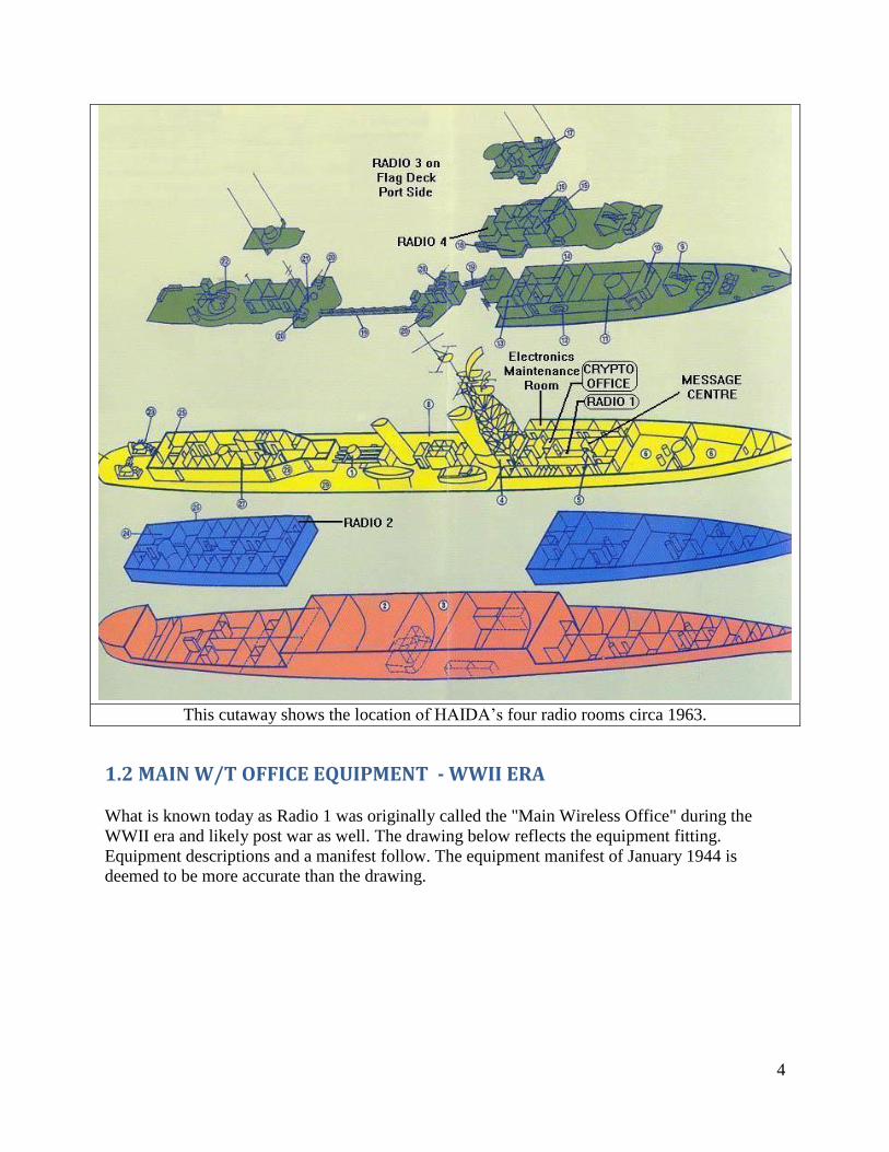
This cutaway shows the location of HAIDA’s four radio rooms circa 1963.
1.2 MAIN W/T OFFICE EQUIPMENT - WWII ERA
What is known today as Radio 1 was originally called the "Main Wireless Office" during the
WWII era and likely post war as well. The drawing below reflects the equipment fitting.
Equipment descriptions and a manifest follow. The equipment manifest of January 1944 is
deemed to be more accurate than the drawing.
5
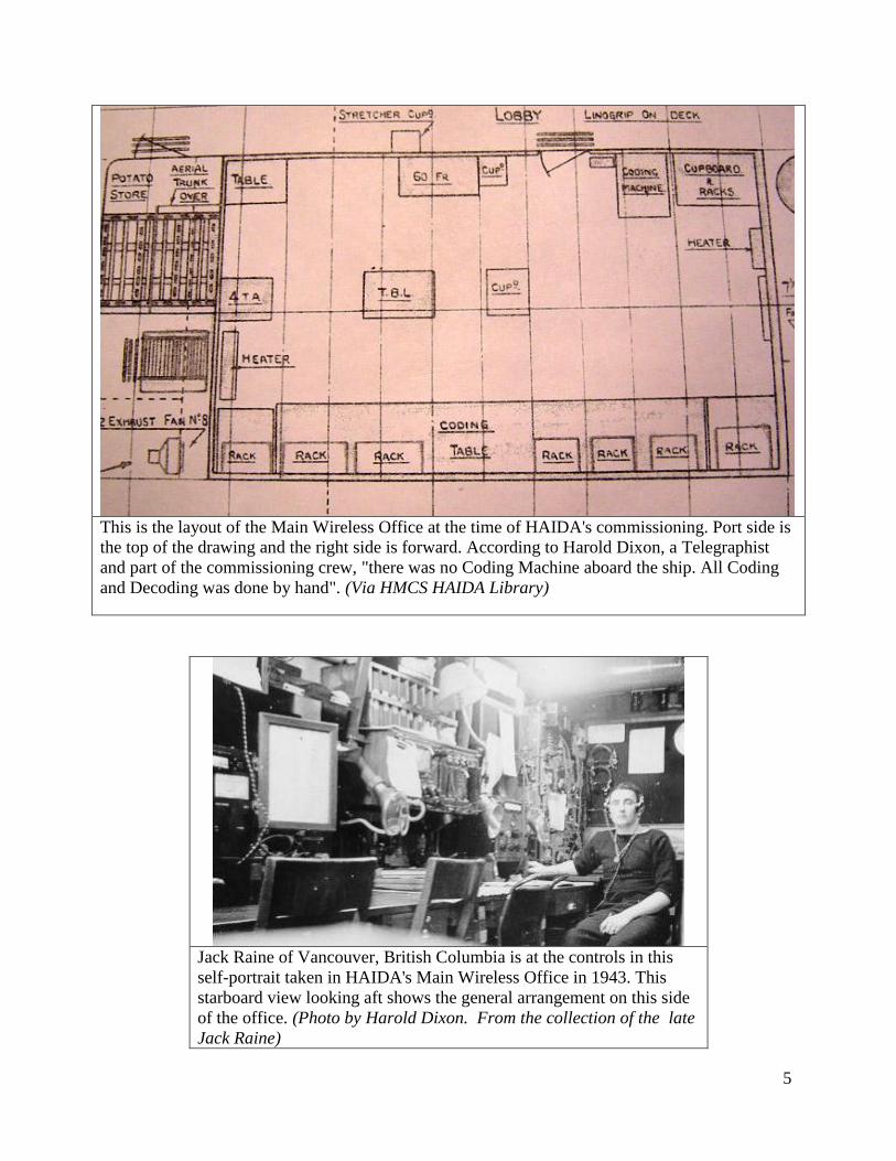
This is the layout of the Main Wireless Office at the time of HAIDA's commissioning. Port side is
the top of the drawing and the right side is forward. According to Harold Dixon, a Telegraphist
and part of the commissioning crew, "there was no Coding Machine aboard the ship. All Coding
and Decoding was done by hand". (Via HMCS HAIDA Library)
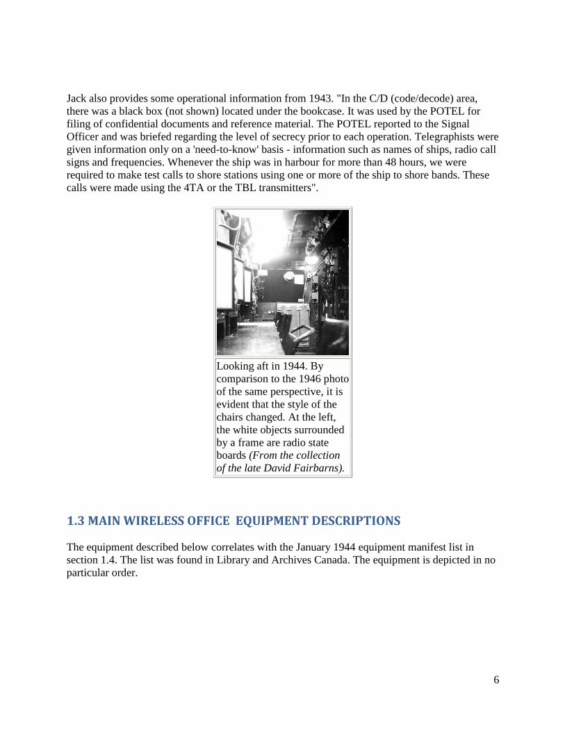
Jack Raine of Vancouver, British Columbia is at the controls in this
self-portrait taken in HAIDA's Main Wireless Office in 1943. This
starboard view looking aft shows the general arrangement on this side
of the office. (Photo by Harold Dixon. From the collection of the late
Jack Raine)
6
Jack also provides some operational information from 1943. "In the C/D (code/decode) area,
there was a black box (not shown) located under the bookcase. It was used by the POTEL for
filing of confidential documents and reference material. The POTEL reported to the Signal
Officer and was briefed regarding the level of secrecy prior to each operation. Telegraphists were
given information only on a 'need-to-know' basis - information such as names of ships, radio call
signs and frequencies. Whenever the ship was in harbour for more than 48 hours, we were
required to make test calls to shore stations using one or more of the ship to shore bands. These
calls were made using the 4TA or the TBL transmitters".
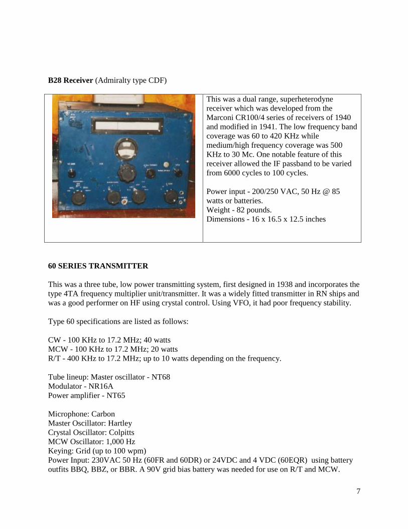
Looking aft in 1944. By
comparison to the 1946 photo
of the same perspective, it is
evident that the style of the
chairs changed. At the left,
the white objects surrounded
by a frame are radio state
boards (From the collection
of the late David Fairbarns).
1.3 MAIN WIRELESS OFFICE EQUIPMENT DESCRIPTIONS
The equipment described below correlates with the January 1944 equipment manifest list in
section 1.4. The list was found in Library and Archives Canada. The equipment is depicted in no
particular order.
7
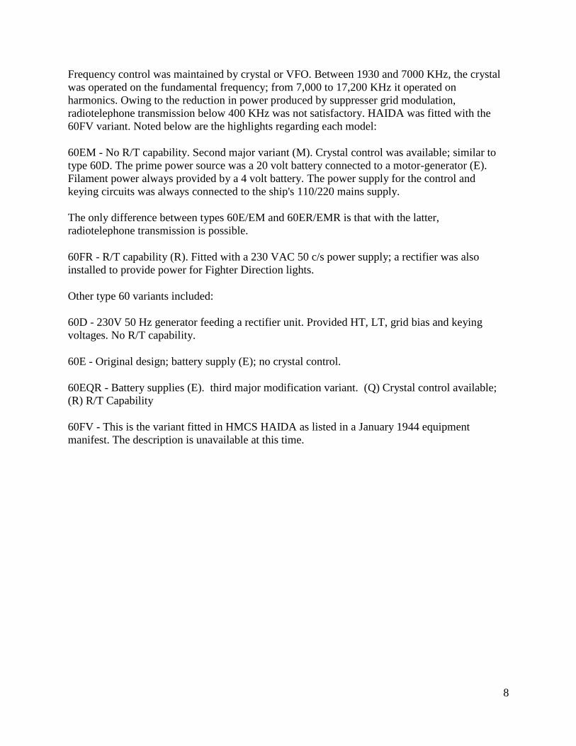
B28 Receiver (Admiralty type CDF)
This was a dual range, superheterodyne
receiver which was developed from the
Marconi CR100/4 series of receivers of 1940
and modified in 1941. The low frequency band
coverage was 60 to 420 KHz while
medium/high frequency coverage was 500
KHz to 30 Mc. One notable feature of this
receiver allowed the IF passband to be varied
from 6000 cycles to 100 cycles.
Power input - 200/250 VAC, 50 Hz @ 85
watts or batteries.
Weight - 82 pounds.
Dimensions - 16 x 16.5 x 12.5 inches
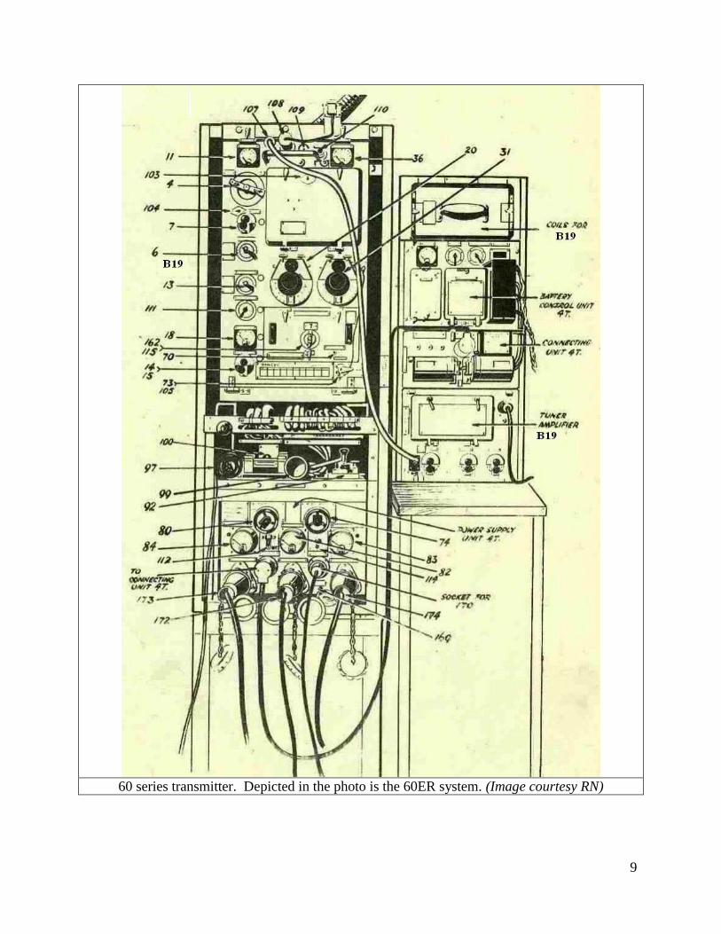
60 SERIES TRANSMITTER
This was a three tube, low power transmitting system, first designed in 1938 and incorporates the
type 4TA frequency multiplier unit/transmitter. It was a widely fitted transmitter in RN ships and
was a good performer on HF using crystal control. Using VFO, it had poor frequency stability.
Type 60 specifications are listed as follows:
CW - 100 KHz to 17.2 MHz; 40 watts
MCW - 100 KHz to 17.2 MHz; 20 watts
R/T - 400 KHz to 17.2 MHz; up to 10 watts depending on the frequency.
Tube lineup: Master oscillator - NT68
Modulator - NR16A
Power amplifier - NT65
Microphone: Carbon
Master Oscillator: Hartley
Crystal Oscillator: Colpitts
MCW Oscillator: 1,000 Hz
Keying: Grid (up to 100 wpm)
Power Input: 230VAC 50 Hz (60FR and 60DR) or 24VDC and 4 VDC (60EQR) using battery
outfits BBQ, BBZ, or BBR. A 90V grid bias battery was needed for use on R/T and MCW.
8
Frequency control was maintained by crystal or VFO. Between 1930 and 7000 KHz, the crystal
was operated on the fundamental frequency; from 7,000 to 17,200 KHz it operated on
harmonics. Owing to the reduction in power produced by suppresser grid modulation,
radiotelephone transmission below 400 KHz was not satisfactory. HAIDA was fitted with the
60FV variant. Noted below are the highlights regarding each model:
60EM - No R/T capability. Second major variant (M). Crystal control was available; similar to
type 60D. The prime power source was a 20 volt battery connected to a motor-generator (E).
Filament power always provided by a 4 volt battery. The power supply for the control and
keying circuits was always connected to the ship's 110/220 mains supply.
The only difference between types 60E/EM and 60ER/EMR is that with the latter,
radiotelephone transmission is possible.
60FR - R/T capability (R). Fitted with a 230 VAC 50 c/s power supply; a rectifier was also
installed to provide power for Fighter Direction lights.
Other type 60 variants included:
60D - 230V 50 Hz generator feeding a rectifier unit. Provided HT, LT, grid bias and keying
voltages. No R/T capability.
60E - Original design; battery supply (E); no crystal control.
60EQR - Battery supplies (E). third major modification variant. (Q) Crystal control available;
(R) R/T Capability
60FV - This is the variant fitted in HMCS HAIDA as listed in a January 1944 equipment
manifest. The description is unavailable at this time.
9
60 series transmitter. Depicted in the photo is the 60ER system. (Image courtesy RN)
10
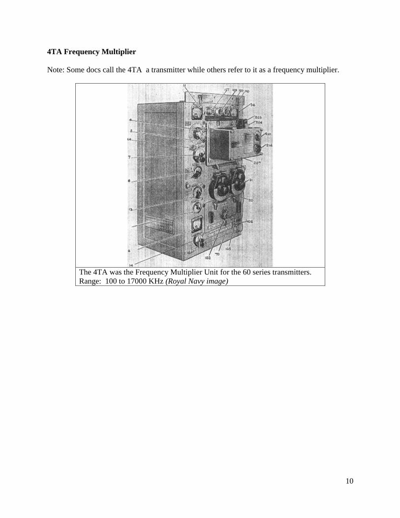
4TA Frequency Multiplier
Note: Some docs call the 4TA a transmitter while others refer to it as a frequency multiplier.
The 4TA was the Frequency Multiplier Unit for the 60 series transmitters.
Range: 100 to 17000 KHz (Royal Navy image)
11
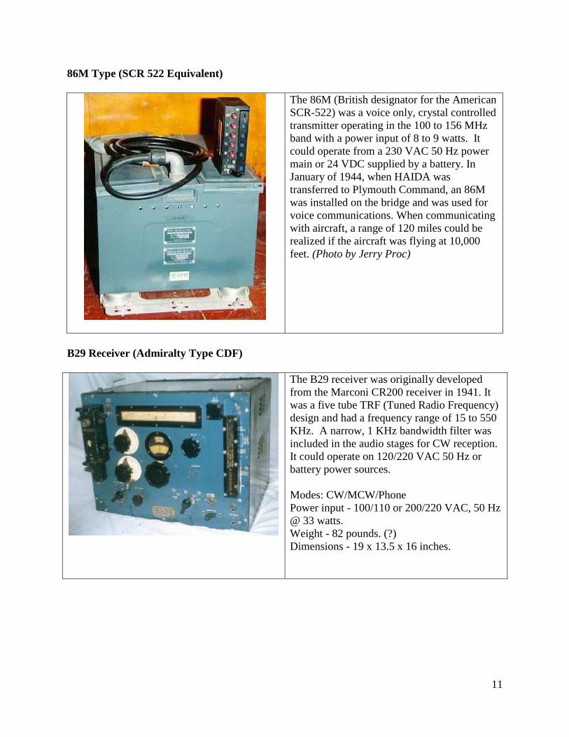
86M Type (SCR 522 Equivalent)
The 86M (British designator for the American
SCR-522) was a voice only, crystal controlled
transmitter operating in the 100 to 156 MHz
band with a power input of 8 to 9 watts. It
could operate from a 230 VAC 50 Hz power
main or 24 VDC supplied by a battery. In
January of 1944, when HAIDA was
transferred to Plymouth Command, an 86M
was installed on the bridge and was used for
voice communications. When communicating
with aircraft, a range of 120 miles could be
realized if the aircraft was flying at 10,000
feet. (Photo by Jerry Proc)
B29 Receiver (Admiralty Type CDF)
The B29 receiver was originally developed
from the Marconi CR200 receiver in 1941. It
was a five tube TRF (Tuned Radio Frequency)
design and had a frequency range of 15 to 550
KHz. A narrow, 1 KHz bandwidth filter was
included in the audio stages for CW reception.
It could operate on 120/220 VAC 50 Hz or
battery power sources.
Modes: CW/MCW/Phone
Power input - 100/110 or 200/220 VAC, 50 Hz
@ 33 watts.
Weight - 82 pounds. (?)
Dimensions - 19 x 13.5 x 16 inches.
12
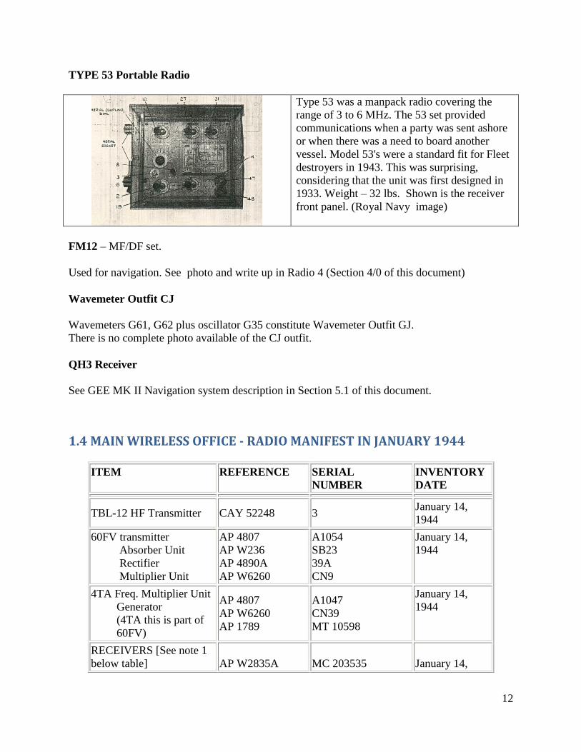
TYPE 53 Portable Radio
Type 53 was a manpack radio covering the
range of 3 to 6 MHz. The 53 set provided
communications when a party was sent ashore
or when there was a need to board another
vessel. Model 53's were a standard fit for Fleet
destroyers in 1943. This was surprising,
considering that the unit was first designed in
1933. Weight – 32 lbs. Shown is the receiver
front panel. (Royal Navy image)
FM12 – MF/DF set.
Used for navigation. See photo and write up in Radio 4 (Section 4/0 of this document)
Wavemeter Outfit CJ
Wavemeters G61, G62 plus oscillator G35 constitute Wavemeter Outfit GJ.
There is no complete photo available of the CJ outfit.
QH3 Receiver
See GEE MK II Navigation system description in Section 5.1 of this document.
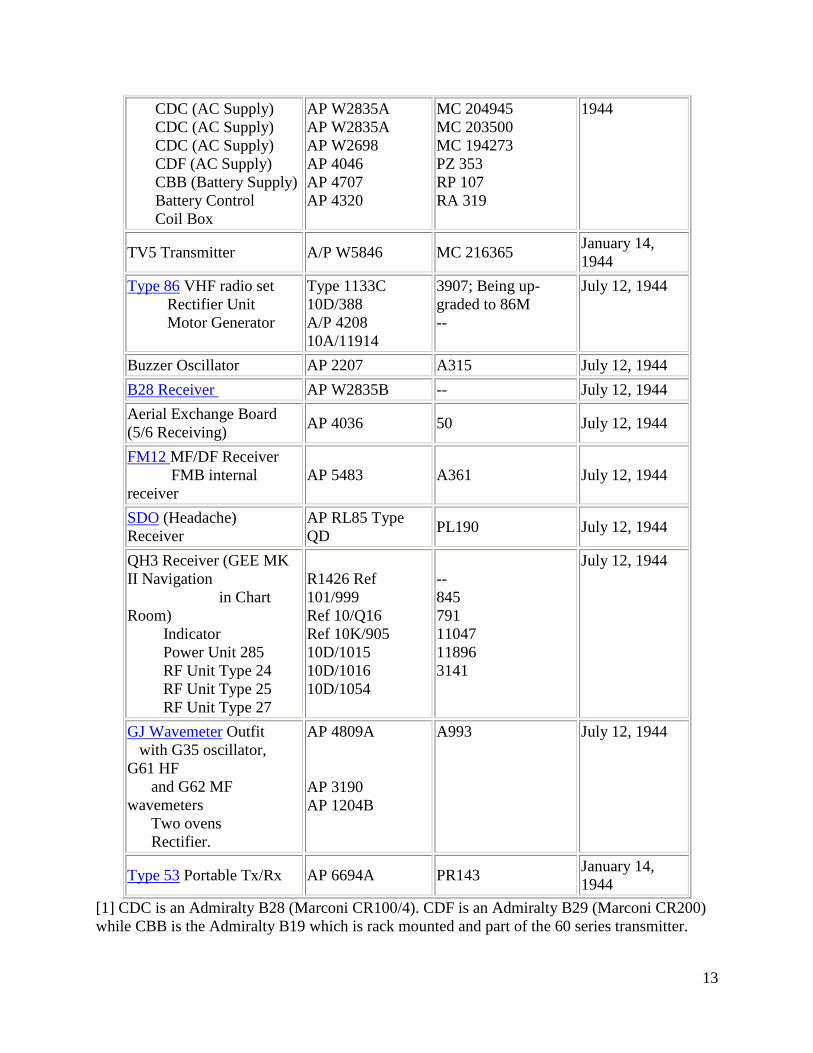
1.4 MAIN WIRELESS OFFICE - RADIO MANIFEST IN JANUARY 1944
ITEM REFERENCE SERIAL
NUMBER
INVENTORY
DATE
TBL-12 HF Transmitter CAY 52248 3 January 14,
1944
60FV transmitter
Absorber Unit
Rectifier
Multiplier Unit
AP 4807
AP W236
AP 4890A
AP W6260
A1054
SB23
39A
CN9
January 14,
1944
4TA Freq. Multiplier Unit
Generator
(4TA this is part of
60FV)
AP 4807
AP W6260
AP 1789
A1047
CN39
MT 10598
January 14,
1944
RECEIVERS [See note 1
below table]
AP W2835A
MC 203535
January 14,
13
CDC (AC Supply)
CDC (AC Supply)
CDC (AC Supply)
CDF (AC Supply)
CBB (Battery Supply)
Battery Control
Coil Box
AP W2835A
AP W2835A
AP W2698
AP 4046
AP 4707
AP 4320
MC 204945
MC 203500
MC 194273
PZ 353
RP 107
RA 319
1944
TV5 Transmitter A/P W5846 MC 216365 January 14,
1944
Type 86 VHF radio set
Rectifier Unit
Motor Generator
Type 1133C
10D/388
A/P 4208
10A/11914
3907; Being up-
graded to 86M
--
July 12, 1944
Buzzer Oscillator AP 2207 A315 July 12, 1944
B28 Receiver AP W2835B -- July 12, 1944
Aerial Exchange Board
(5/6 Receiving) AP 4036 50 July 12, 1944
FM12 MF/DF Receiver
FMB internal
receiver
AP 5483
A361
July 12, 1944
SDO (Headache)
Receiver
AP RL85 Type
QD PL190 July 12, 1944
QH3 Receiver (GEE MK
II Navigation
in Chart
Room)
Indicator
Power Unit 285
RF Unit Type 24
RF Unit Type 25
RF Unit Type 27
R1426 Ref
101/999
Ref 10/Q16
Ref 10K/905
10D/1015
10D/1016
10D/1054
--
845
791
11047
11896
3141
July 12, 1944
GJ Wavemeter Outfit
with G35 oscillator,
G61 HF
and G62 MF
wavemeters
Two ovens
Rectifier.
AP 4809A
AP 3190
AP 1204B
A993 July 12, 1944
Type 53 Portable Tx/Rx AP 6694A PR143 January 14,
1944
[1] CDC is an Admiralty B28 (Marconi CR100/4). CDF is an Admiralty B29 (Marconi CR200)
while CBB is the Admiralty B19 which is rack mounted and part of the 60 series transmitter.
14
1.5 THE HEADACHE FUNCTION
Headache was the codename was applied to the shipborne sections of 'Y' intelligence who were
charged with the task of intercepting and reading German low-grade radiotelephone traffic which
had been steadily introduced since 1941. Generally speaking, Headache operators came from a
Special Branch of the RN and were fluent in German. 'Every important warship in the D-Day
armada and the bombing force was provided with a Headache Unit for the interception and
interpretation of enemy air and naval R/T on VHF. Fifty warships in all were fitted with
Headache units.
Lawson Gregory of Woking, England relates his experiences as a Headache operator during
WWII. "Having knowledge of German, I volunteered for any job where I could be of more use.
When my ship, HMS Zulu was sunk during the raid on Tobruk in September 1942, I was
initiated into Headache. Once I was drafted to a ship, I was accompanied with a special VHF
radio set, plus aerial and of course a copy of the code used by the enemy. The presence of a
Headache operator usually meant the ship would probably be very close to the Germans. On
HAIDA, my action station was in a small office just below and aft of the bridge. Communication
with the bridge was through voice pipe. Even when not at action stations, I would listen in. On
one occasion, enemy aircraft were giving a sighting report on HAIDA's position while she was in
Plymouth! Overall, it was a fascinating job almost guaranteeing action". On HAIDA, one of the
tags on a telephone junction box in the Fire Control Room makes reference to the Headache
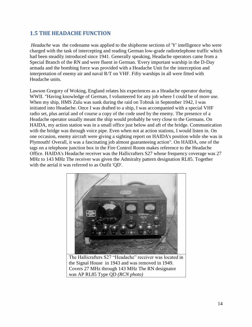
Office. HAIDA's Headache receiver was the Hallicrafters S27 whose frequency coverage was 27
MHz to 143 MHz The receiver was given the Admiralty pattern designation RL85. Together
with the aerial it was referred to as Outfit 'QD'.
The Hallicrafters S27 “Headache” receiver was located in
the Signal House in 1943 and was removed in 1949.
Covers 27 MHz through 143 MHz The RN designator
was AP RL85 Type QD (RCN photo)
15
1.6 TRAINING RCN TELEGRAPHISTS
The Signal School at St. Hyacinthe, Quebec was very instrumental in training thousands of
wireless operators during World War II. It had moved from Halifax to St. Hyacinthe in the
summer of 1941. Modern buildings, numbering about 73, were spread over a 25 acre site. This
facility housed almost 3200 officers, ratings and Wrens, involved in all phases of
communications training. This was a sharp contrast to earlier complements, when for example, in
December of 1942, the complement stood at 921, of which 40 were officers. It had become
relatively easy for St. Hyacinthe to produce good communicators, but it was not always the case.
Since the beginning of the war, effective training in the signals branch had been made difficult
by poor selection of recruits. In December, 1940, an educational standard for visual signalman
(V/S) and wireless telegraphists (W/T) had been established, namely that ratings should have at
least two years of high school.
In the years prior to WWII, training for telegraphists took about a year. After the war started, that
period was reduced to approximately 3 months with intensive work. The test given at the end of
the course varied between thirty and thirty five words per minute and one's marks were
commensurate with ability. If a student failed his exam after six weeks, he either was assigned as
a stoker or seaman until the summer of 1941. After that, the RCN decided that they would start a
Coders course and those who failed as Signalmen or W/T operators would become coders after
taking a six week course. As the need for more coders rose, the RCN recruited men just for the
Coding branch. Coders took a plain text message and encoded it prior to transmission over the
radio. They also decoded incoming messages into plain text.
By 1944, great improvements in training had been made, and despite any earlier apprehensions,
St. Hyacinthe was able to turn out a proficient and worthwhile product for the ships and
establishments of the navy. Communications training at St. Hyacinthe now consisted of courses
for visual signalmen, wireless telegraphists, coders, radar operators, and radio artificers. Note
that 'radar' was an American term. In the RCN, the term R.D.F (Radio Direction Finding) was
used to reference people and equipment . However, order N.S. 1052-1-1 issued on 10-7-43
instructed that the term RDF be dropped and replaced with the updated term radar for all
correspondence and future publications. Personnel would be referred to as Radar Officers,
Leading Seaman Radar 1 etc. but no change to the term Radio Artificer.
A small number of ratings were specially trained as convoy signalmen. Their duty, essential
during wireless silence, was to serve in merchant ships so that these ships could maintain proper
contact with the warships forming the escort.
Telegraphists, began their studies by entering the 'Morse Pool', also known as the 'Buzzer Pool'.
In 1941, ratings could not join a regular class until they could read Morse at 12 words per
minute. The Morse Pool, provided the opportunity to gain this speed with the average length of
time spent there being five and a half weeks. The regular course of twenty one weeks duration,
covered a general knowledge of receivers and transmitters, wireless organization, direction
finding, radio telephone procedure, along with transmitting and receiving Morse at 22 WPM.
16
Typewriters did not come into vogue until late in the war, so all CW had to be copied with pencil
and paper. Telegraphic typewriters were first issued to HMC Ships starting around mid-1945.
Practical experience in W/T and R/T was obtained through the use of portable sets and through a
Navy-Air Force program of establishing communications with the RCAF No. 1 Wireless
Training School in Montreal. The V/S3 and W/T3 courses for Leading Rate started in the fall of
1940 at Halifax, and continued at St. Hyacinthe. The V/S2 and W/T2 courses, for qualification to
Petty Officer, started a year later at St. Hyacinthe.
Code work was introduced in the Spring of 1941. The coder's course at the St. Hyacinthe Signal
School was about four weeks in duration. The relative length of their course in no way
diminished their value to the communications branch of a ship, because V/S and W/T ratings
could also do code work. A long signal course for officers had its inauguration in July 1944. This
course, lasting for seven months, qualified the officers for specialist duties and covered all forms
of communication including radar and Loran. Specialist courses were also given for WRCNS
(Wren) officers to prepare them for duties as signal officers at shore bases.
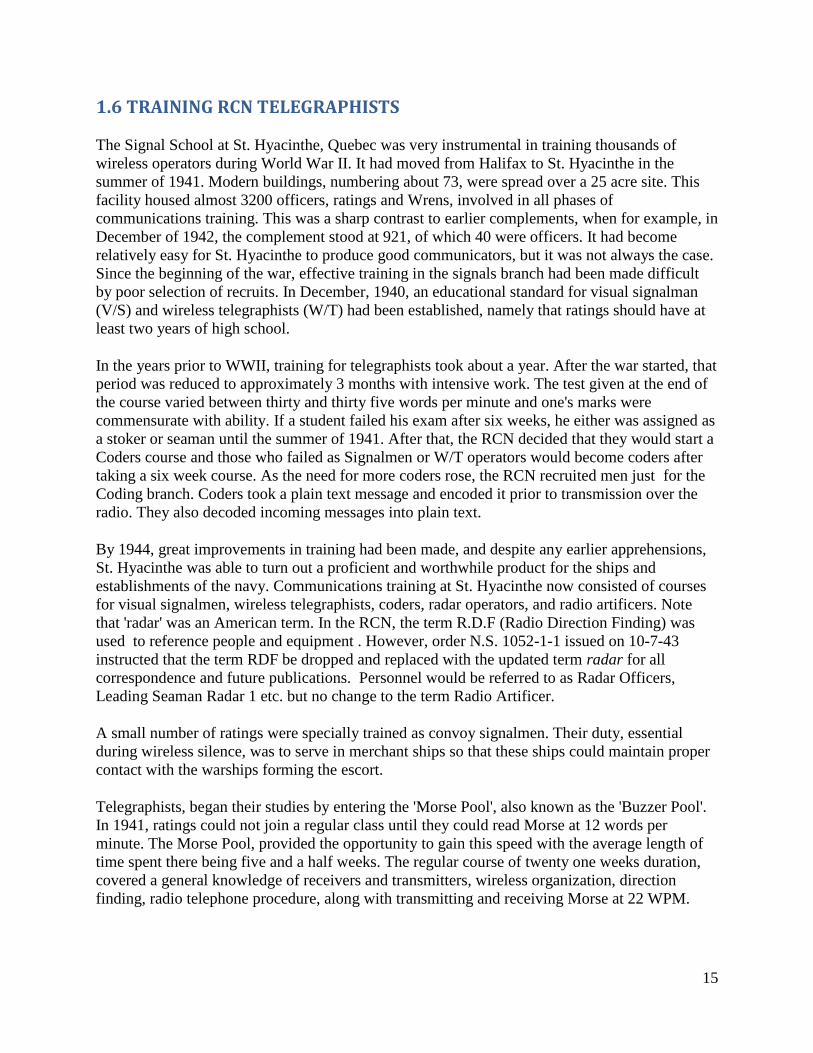
This type of key or similar models would have been used
aboard HAIDA during WWII. This particular example is an
Admiralty Pattern No. 7681. (Photo courtesy of Meir Ben-
Dror).
Harold Dixon also remembers his action station on the bridge. "I was on the bridge during all
action stations and positioned myself in a little hole just behind the glass shield .There I used a
spit earphone with VHF traffic in one ear and CW in the other ear. I could operate VHF from
there and optionally send the audio to a speaker. Also fitted there was a remote CW key. All
orders for the alteration of ship's course came by CW from the group leader and the execute
order was sent as a long dash.
Haida and other ships of the 10th Destroyer Flotilla departed Plymouth just about every night
around six o'clock to patrol the French coast. As we approached the French coast, our orders
17
would arrive if there was any German activity observed from the French side. These were coded
numeric messages for the most part. There was very little plain text. Harry DeWolf preferred to
have operators on the bridge who could copy 20 wpm versus the 12 wpm requirement of the
Signals School.
When destroyers were leaving on convoy or any other duty, the command destroyer would
contact each ship by CW as a signal check. We were instructed to reduce power on the
transmitters as low as we could make it - usually around 10 watts.
When in port there was a daily CW proficiency session directly aimed at the junior operators.
Shore radio would send out groups of numbers and also clear text. After they finished
transmissions, the operator composed a similar type message and would send it back to shore
radio. The shore station would then provide a proficiency report back to Capt. Harry DeWolf "
Coders, who encrypted plain text messages and decoded enciphered messages, messed together
on the same deck. While on duty and when they weren't at action stations, the Coders had their
own room for coding and decoding messages. When a radio operator received a ciphered
message, he would bring it to the Coding Office for further processing. The only time the Coders
were in the Main radio office was during actions stations. By being there, messages could be
decoded much quicker before being sent up to the bridge". Aboard HAIDA, a Coders Office has
never been located so it's presumed that the Coding function was integral with the Main Wireless
Office.
At the peak of strength, the communications branch of the Royal Canadian Navy contained about
9,300 ratings. Of these, 3,200 were Telegraphists, 2,338 were Signalmen, about 1,000 coders,
2,200 Radar Operators, and 399 were Radio Artificers. It is significant to note that the bulk of
these were trained at St. Hyacinthe.
1.7 PROJECT ACCUMULATOR
Researcher Roger Basford provides a former TOP SECRET document from the UK National
Archive which summarizes the involvement of His Majesty's Canadian ships HAIDA and
HURON in Operation Accumulator, on 12/13 June, 1944.
In slightly less than a week after D-Day, there was concern in Allied Command that the Germans
might move troops stationed in the western part of the Cherbourg Peninsula [1] towards Utah
and Omaha beaches at Normandy. In addition, it was hoped that a feint in the western part of the
Cherbourg Peninsula would draw off part of the heavy German forces defending the valuable
seaport at Cherbourg and thus facilitate its capture by the armies of liberation.
Early in the morning of June 13, 1944, HMC Ships HAIDA and HURON were tasked with the
mission of creating bogus radio traffic in order to make the Germans believe that Allied troops
would be landing on the west coast of the Cherbourg Peninsula. The diversionary sweep was
developed and supported by the British Army.
18
This diversion was staged on extremely short notice. HAIDA and HURON were the only ships
available for the task. The phony radio traffic would be most convincing if it represented urgent,
last-minute rearrangement of plans and if it also looked like radio silence had been broken at sea.
A "script" was developed for HAIDA and HURON by the British 21 Army Group staff officers.
Appropriate wireless sets (WS12 and WS22 sets) were borrowed from the Naval Mobile
Deception Unit and flown to Plymouth where they were installed in the two destroyers.
Operators were drawn from special (RN) naval radio deception units under the code name CLH.
Major Rooke of the 21 Army Unit, together with a Leading Telegraphist from the Naval
Deception Unit (NDU,) sailed in HAIDA. Rooke assumed the role of a Brigade Commander.
Sub Lt. Jones of NDU boarded HURON. The script was “cast” among the participants and
rehearsed aboard HAIDA. Both vessels slipped their lines and sailed at 20:00 on June 12.
Due to lack of co-ordination with other services and units, an RAF reconnaissance aircraft from
19 Group sent a sighting report of two unidentified ships (HAIDA and HURON) and their
positions at 2309. At the time the report was made, the visibility was good so faulty ship
recognition by this particular aircraft was to blame for the error. At 23:42, the aircraft reported
that the two ships were friendly. There was lack of liaison between A.C.H.Q Plymouth and 19th
Group. The report itself was made in Aircraft Reporting Code and fortunately there was no
visible reaction on the part of the German military. This non-reaction by the Germans did
however, instill confidence in the security of the Aircraft Reporting Code. This action might
have alerted German radio monitors to something suspicious.
At 0150, Major Rooke reports that he is unable to get his WS-22 radios "netted" [2] correctly due
to the short amount of available time. As a result, the script was hastily “recast” by Lt. Jones so
that HURON could simulate both sets of signals.
Ahead of the planned flow of bogus traffic, a message was transmitted to indicate a potential
assault by ' Q ' division on the beach area north of Granville in the early hours of June 13. Next a
message is sent to indicate a defective plummer bearing in the vessel carrying the assault troops
of ' T ' battalion. The vessel must reduce its speed to 8 knots. As a result, it will alter the arrival
time of the assault battalion. It is reported as an 'IMMEDIATE' message. In response, the
commander of 'A' battalion breaks radio silence to respond to the message.
The transmission of bogus radio messages began at 0258 on June 13 and lasted until 0327. The
result, as heard, was considered satisfactory. However, there was no reaction from the Germans.
No forces were moved from the port of Cherbourg or surrounding area. The mock landing was
heralded by a heavy Allied air bombardment of the beaches and HAIDA's men watched with
considerable interest, and with some anxiety, the massive fireworks display bursting above the
fiercely contested peninsula. The men agreed it was not exactly their "cup of tea" and no one was
any the sadder when at last the order was given to clear the area and shape course for the more
familiar mid-Channel waters where a destroyer had some searoom in the event of an encounter
with enemy forces.
19
The frequencies used for this operation are as follows:
2300 KHz for ship to shore.
2640 KHz for the No.12 wireless sets. There was one each in Haida and Huron.
4115 KHz for the No.22 wireless sets. There were two each in Haida and Huron.
In total, there were six, scripted, multipart messages sent with appropriate responses within the
allotted time window. This involved the non-existent 'A', 'S' ,'T', and 'U' Battalions and 'Q'
Division.
Wirelesses sets 12 and 22 were used for this operation.
1.8 DUTIES OF A TELEGRAPHIST
This excerpt, which defined the duties of a Telegraphist, was provided by WWII Telegraphist
George Crowell.
He is responsible for the care and maintenance of W/T gear. Any defects beyond his capabilities
are to be reported to an Special Operator who will arrange for repairs with shore staff.
He is to have spare parts as far as allowed by stores and is also responsible for the correction of
Signal Publications other than Visual Signalling. He will also correct all other publications on
board. They are to be kept up to date at all times.
He is to keep the key to the W/T office in his possession, properly secured to his person and
turning them into the Duty Officer before going ashore. The W/T office is to be locked on
entering harbour and is to remain locked until leaving port again. Exceptions to this are:
- when occupied by the Telegraphist (Tel) or RDF operator on ship's business
- when work is being done by maintenance however a Tel or term operator is to be present.
He is to make himself familiar with the contents of all W/T publications aboard and amendments
thereto issued from time to time. He is to maintain the required logs dependent on the type of
work carried out. He is responsible for the ships clocks making sure they are compared against a
time signal station. He is responsible for the cleanliness of the W/T office.
20
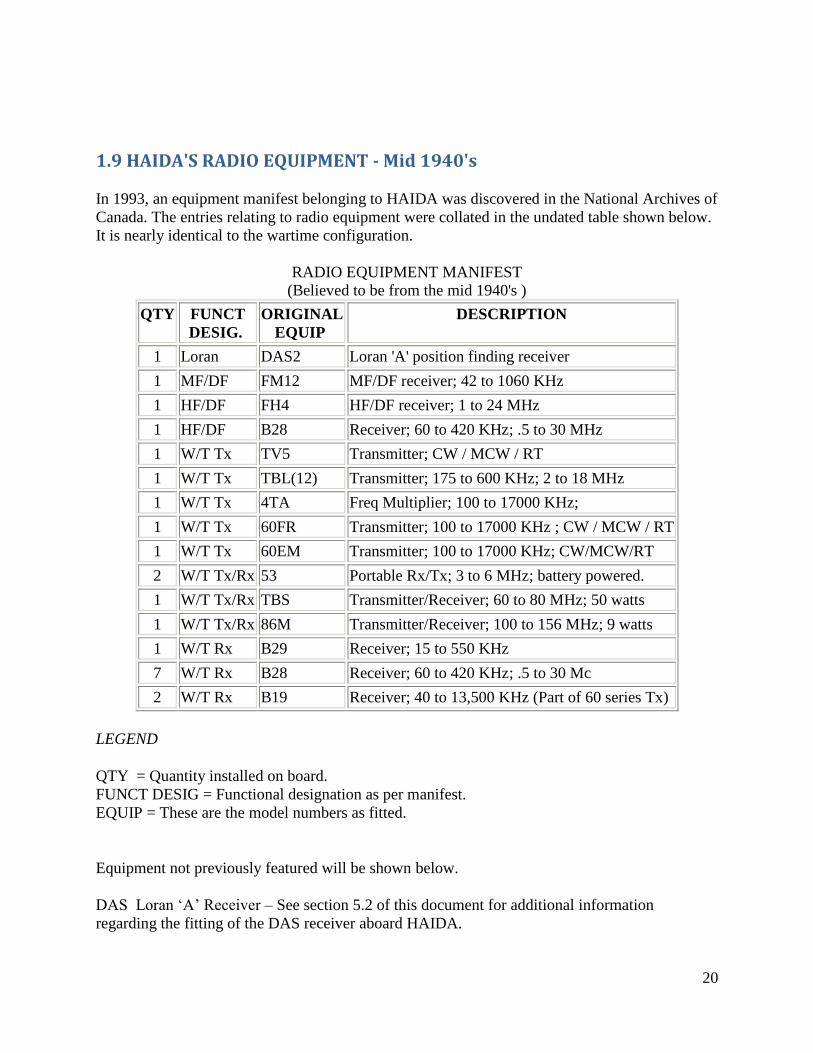
1.9 HAIDA'S RADIO EQUIPMENT - Mid 1940's
In 1993, an equipment manifest belonging to HAIDA was discovered in the National Archives of
Canada. The entries relating to radio equipment were collated in the undated table shown below.
It is nearly identical to the wartime configuration.
RADIO EQUIPMENT MANIFEST
(Believed to be from the mid 1940's )
QTY FUNCT
DESIG.
ORIGINAL
EQUIP
DESCRIPTION
1 Loran DAS2 Loran 'A' position finding receiver
1 MF/DF FM12 MF/DF receiver; 42 to 1060 KHz
1 HF/DF FH4 HF/DF receiver; 1 to 24 MHz
1 HF/DF B28 Receiver; 60 to 420 KHz; .5 to 30 MHz
1 W/T Tx TV5 Transmitter; CW / MCW / RT
1 W/T Tx TBL(12) Transmitter; 175 to 600 KHz; 2 to 18 MHz
1 W/T Tx 4TA Freq Multiplier; 100 to 17000 KHz;
1 W/T Tx 60FR Transmitter; 100 to 17000 KHz ; CW / MCW / RT
1 W/T Tx 60EM Transmitter; 100 to 17000 KHz; CW/MCW/RT
2 W/T Tx/Rx 53 Portable Rx/Tx; 3 to 6 MHz; battery powered.
1 W/T Tx/Rx TBS Transmitter/Receiver; 60 to 80 MHz; 50 watts
1 W/T Tx/Rx 86M Transmitter/Receiver; 100 to 156 MHz; 9 watts
1 W/T Rx B29 Receiver; 15 to 550 KHz
7 W/T Rx B28 Receiver; 60 to 420 KHz; .5 to 30 Mc
2 W/T Rx B19 Receiver; 40 to 13,500 KHz (Part of 60 series Tx)
LEGEND
QTY = Quantity installed on board.
FUNCT DESIG = Functional designation as per manifest.
EQUIP = These are the model numbers as fitted.
Equipment not previously featured will be shown below.
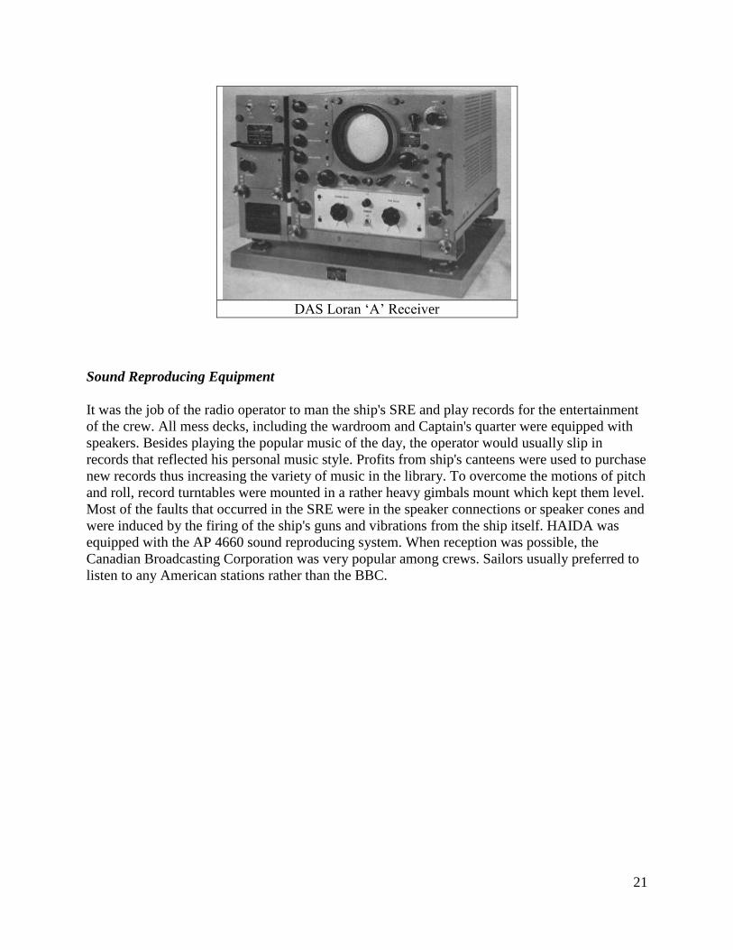
DAS Loran ‘A’ Receiver – See section 5.2 of this document for additional information
regarding the fitting of the DAS receiver aboard HAIDA.
21
DAS Loran ‘A’ Receiver
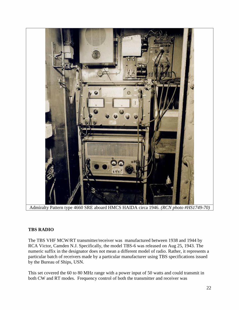
Sound Reproducing Equipment
It was the job of the radio operator to man the ship's SRE and play records for the entertainment
of the crew. All mess decks, including the wardroom and Captain's quarter were equipped with
speakers. Besides playing the popular music of the day, the operator would usually slip in
records that reflected his personal music style. Profits from ship's canteens were used to purchase
new records thus increasing the variety of music in the library. To overcome the motions of pitch
and roll, record turntables were mounted in a rather heavy gimbals mount which kept them level.
Most of the faults that occurred in the SRE were in the speaker connections or speaker cones and
were induced by the firing of the ship's guns and vibrations from the ship itself. HAIDA was
equipped with the AP 4660 sound reproducing system. When reception was possible, the
Canadian Broadcasting Corporation was very popular among crews. Sailors usually preferred to
listen to any American stations rather than the BBC.
22
Admiralty Pattern type 4660 SRE aboard HMCS HAIDA circa 1946. (RCN photo #HS1749-70)
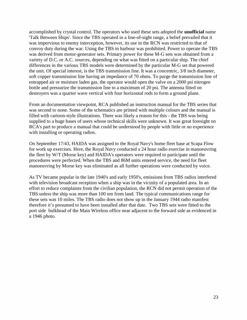
TBS RADIO
The TBS VHF MCW/RT transmitter/receiver was manufactured between 1938 and 1944 by
RCA Victor, Camden N.J. Specifically, the model TBS-6 was released on Aug 25, 1943. The
numeric suffix in the designator does not mean a different model of radio. Rather, it represents a
particular batch of receivers made by a particular manufacturer using TBS specifications issued
by the Bureau of Ships, USN.
This set covered the 60 to 80 MHz range with a power input of 50 watts and could transmit in
both CW and RT modes. Frequency control of both the transmitter and receiver was
23
accomplished by crystal control. The operators who used these sets adopted the unofficial name
'Talk Between Ships'. Since the TBS operated in a line-of-sight range, a belief prevailed that it
was impervious to enemy interception, however, its use in the RCN was restricted to that of
convoy duty during the war. Using the TBS in harbour was prohibited. Power to operate the TBS
was derived from motor-generator sets. Primary power for these M-G sets was obtained from a
variety of D.C. or A.C. sources, depending on what was fitted on a particular ship. The chief
differences in the various TBS models were determined by the particular M-G set that powered
the unit. Of special interest, is the TBS transmission line. It was a concentric, 3/8 inch diameter,
soft copper transmission line having an impedance of 70 ohms. To purge the transmission line of
entrapped air or moisture laden gas, the operator would open the valve on a 2000 psi nitrogen
bottle and pressurize the transmission line to a maximum of 20 psi. The antenna fitted on
destroyers was a quarter wave vertical with four horizontal rods to form a ground plane.
From an documentation viewpoint, RCA published an instruction manual for the TBS series that
was second to none. Some of the schematics are printed with multiple colours and the manual is
filled with cartoon-style illustrations. There was likely a reason for this - the TBS was being
supplied to a huge bases of users whose technical skills were unknown. It was great foresight on
RCA's part to produce a manual that could be understood by people with little or no experience
with installing or operating radios.
On September 17/43, HAIDA was assigned to the Royal Navy's home fleet base at Scapa Flow
for work up exercises. Here, the Royal Navy conducted a 24 hour radio exercise in manoeuvring
the fleet by W/T (Morse key) and HAIDA's operators were required to participate until the
procedures were perfected. When the TBS and 86M units entered service, the need for fleet
manoeuvring by Morse key was eliminated as all further operations were conducted by voice.
As TV became popular in the late 1940's and early 1950's, emissions from TBS radios interfered
with television broadcast reception when a ship was in the vicinity of a populated area. In an
effort to reduce complaints from the civilian population, the RCN did not permit operation of the
TBS unless the ship was more than 100 nm from land. The typical communications range for
these sets was 10 miles. The TBS radio does not show up in the January 1944 radio manifest
therefore it’s presumed to have been installed after that date. Two TBS sets were fitted to the
port side bulkhead of the Main Wireless office near adjacent to the forward side as evidenced in
a 1946 photo.
24
Top- TBS receiver. Bottom – TBS Transmitter (Photo by
Jerry Proc)
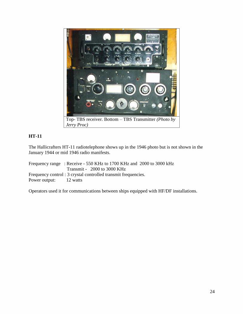
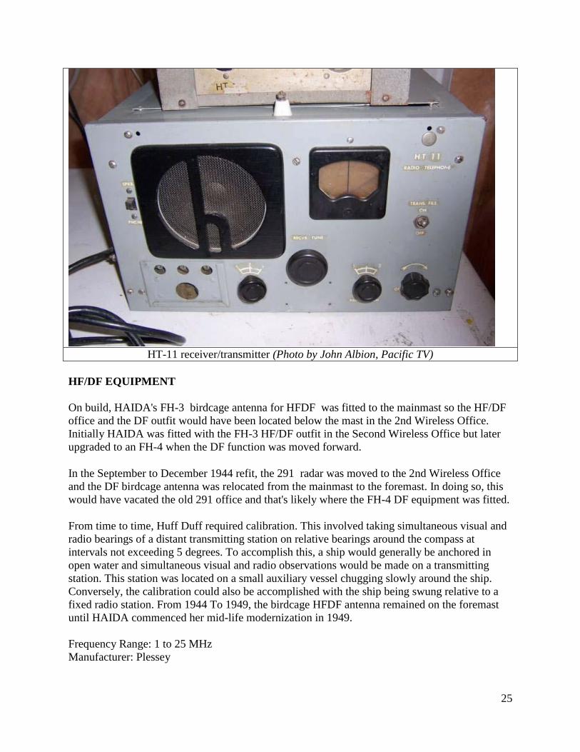
HT-11
The Hallicrafters HT-11 radiotelephone shows up in the 1946 photo but is not shown in the
January 1944 or mid 1946 radio manifests.
Frequency range : Receive - 550 KHz to 1700 KHz and 2000 to 3000 kHz
Transmit - 2000 to 3000 KHz
Frequency control : 3 crystal controlled transmit frequencies.
Power output: 12 watts
Operators used it for communications between ships equipped with HF/DF installations.
25
HT-11 receiver/transmitter (Photo by John Albion, Pacific TV)
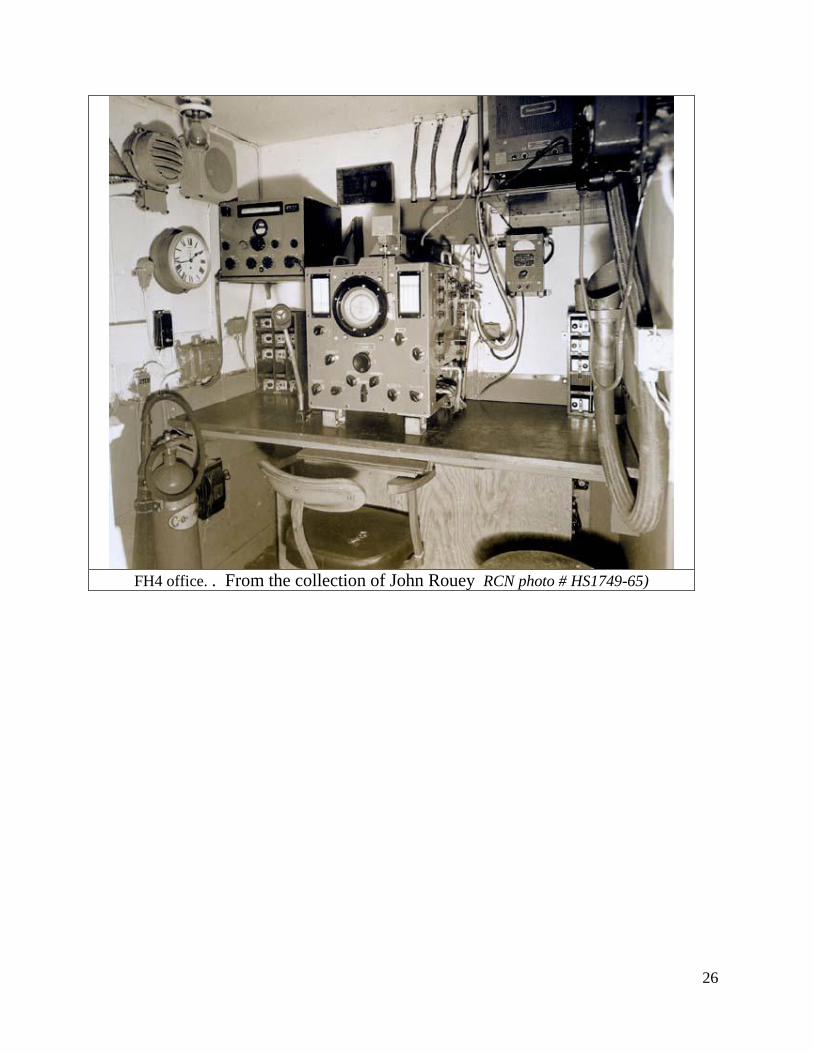
HF/DF EQUIPMENT
On build, HAIDA's FH-3 birdcage antenna for HFDF was fitted to the mainmast so the HF/DF
office and the DF outfit would have been located below the mast in the 2nd Wireless Office.
Initially HAIDA was fitted with the FH-3 HF/DF outfit in the Second Wireless Office but later
upgraded to an FH-4 when the DF function was moved forward.
In the September to December 1944 refit, the 291 radar was moved to the 2nd Wireless Office
and the DF birdcage antenna was relocated from the mainmast to the foremast. In doing so, this
would have vacated the old 291 office and that's likely where the FH-4 DF equipment was fitted.
From time to time, Huff Duff required calibration. This involved taking simultaneous visual and
radio bearings of a distant transmitting station on relative bearings around the compass at
intervals not exceeding 5 degrees. To accomplish this, a ship would generally be anchored in
open water and simultaneous visual and radio observations would be made on a transmitting
station. This station was located on a small auxiliary vessel chugging slowly around the ship.
Conversely, the calibration could also be accomplished with the ship being swung relative to a
fixed radio station. From 1944 To 1949, the birdcage HFDF antenna remained on the foremast
until HAIDA commenced her mid-life modernization in 1949.
Frequency Range: 1 to 25 MHz
Manufacturer: Plessey
26
FH4 office. . From the collection of John Rouey RCN photo # HS1749-65)
27
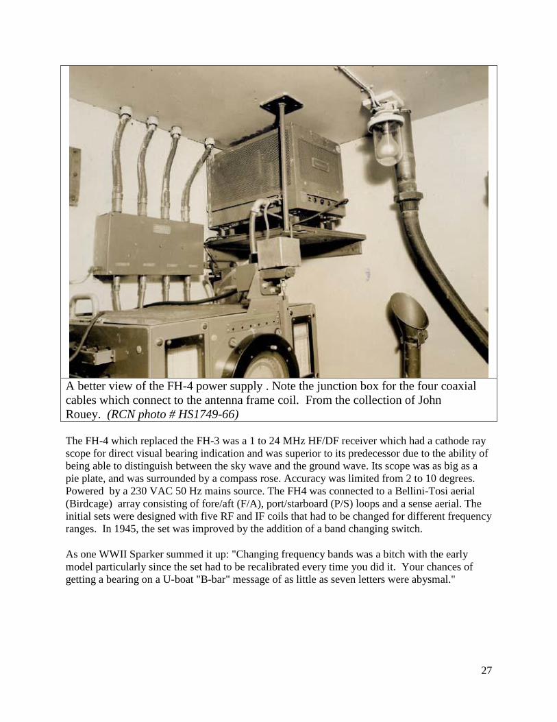
A better view of the FH-4 power supply . Note the junction box for the four coaxial
cables which connect to the antenna frame coil. From the collection of John
Rouey. (RCN photo # HS1749-66)
The FH-4 which replaced the FH-3 was a 1 to 24 MHz HF/DF receiver which had a cathode ray
scope for direct visual bearing indication and was superior to its predecessor due to the ability of
being able to distinguish between the sky wave and the ground wave. Its scope was as big as a
pie plate, and was surrounded by a compass rose. Accuracy was limited from 2 to 10 degrees.
Powered by a 230 VAC 50 Hz mains source. The FH4 was connected to a Bellini-Tosi aerial
(Birdcage) array consisting of fore/aft (F/A), port/starboard (P/S) loops and a sense aerial. The
initial sets were designed with five RF and IF coils that had to be changed for different frequency
ranges. In 1945, the set was improved by the addition of a band changing switch.
As one WWII Sparker summed it up: "Changing frequency bands was a bitch with the early
model particularly since the set had to be recalibrated every time you did it. Your chances of
getting a bearing on a U-boat "B-bar" message of as little as seven letters were abysmal."
28
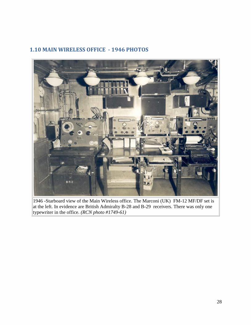
1.10 MAIN WIRELESS OFFICE - 1946 PHOTOS
1946 -Starboard view of the Main Wireless office. The Marconi (UK) FM-12 MF/DF set is
at the left. In evidence are British Admiralty B-28 and B-29 receivers. There was only one
typewriter in the office. (RCN photo #1749-61)
29
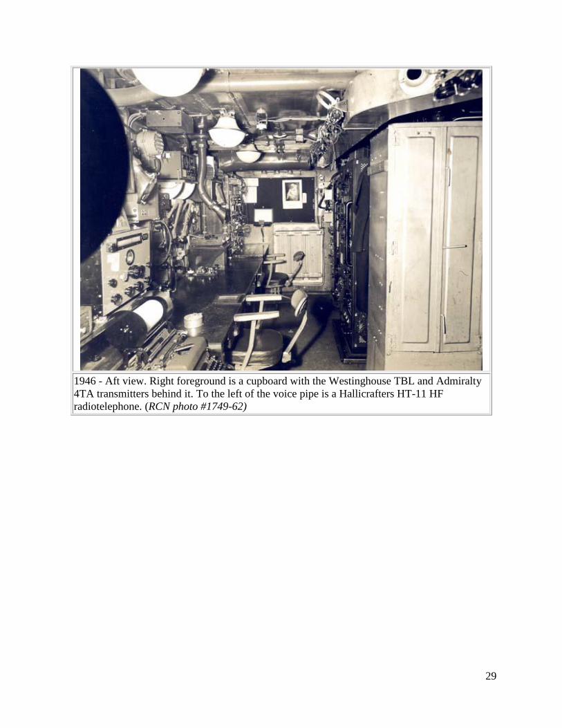
1946 - Aft view. Right foreground is a cupboard with the Westinghouse TBL and Admiralty
4TA transmitters behind it. To the left of the voice pipe is a Hallicrafters HT-11 HF
radiotelephone. (RCN photo #1749-62)
30
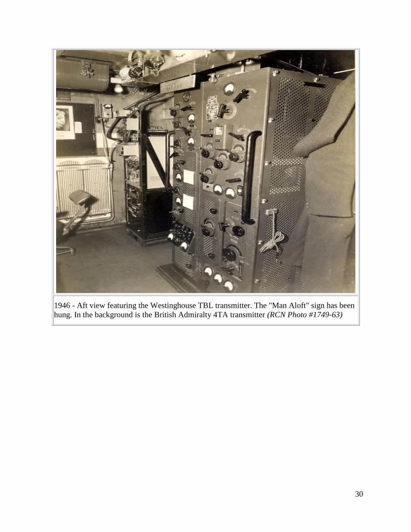
1946 - Aft view featuring the Westinghouse TBL transmitter. The "Man Aloft" sign has been
hung. In the background is the British Admiralty 4TA transmitter (RCN Photo #1749-63)
31
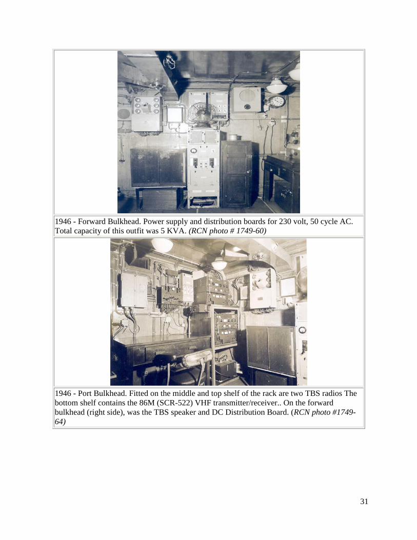
1946 - Forward Bulkhead. Power supply and distribution boards for 230 volt, 50 cycle AC.
Total capacity of this outfit was 5 KVA. (RCN photo # 1749-60)
1946 - Port Bulkhead. Fitted on the middle and top shelf of the rack are two TBS radios The
bottom shelf contains the 86M (SCR-522) VHF transmitter/receiver.. On the forward
bulkhead (right side), was the TBS speaker and DC Distribution Board. (RCN photo #1749-
64)
32
1.11 RADIO 1 EQUIPMENT - 1950’s
In the 1949/50 period, destroyers had a TBS transmitter/receiver set (60 to 80 MHz) for the
principal manoeuvring circuit, and the TDQ/RCK (100 to 160 MHz) for the Plot/AIC/CIC
circuit. There were other circuits for purposes of air communications.
Lt. Cdr. Frank J. Dunbar reflects on this period. "It wasn't until the advent of UHF that we had
the equipment to guard several circuits. HAIDA was the first RCN ship to be fitted with UHF.
We were assigned in the fall of 1949 (or possibly 1950) as the token Canadian presence in a
USN Task Force that was to conduct an amphibious operation in Labrador. The arrangements for
the exercise had been completed with the UK, but when Newfoundland became part of Canada,
we had to at least take a token part. It was a 50/50 chance as to which ship was chosen, because
only HAIDA and MICMAC were in commission on the East Coast. However, the USN had gone
completely to UHF by then, so we were sent down to Norfolk Virginia to have a couple of UHF
sets (URT/URR) installed just for the exercise.
I remember that we had next to no air information in the exercise, let alone shore bombardment
circuits. But we did get fresh white bread from the freezers of the USN supply ships, and fresh
cod which came from jigging over the ship's side. Which leads me to think that only one
TDQ/RCK was left in each ship during the UHF conversion in the early 50's in order to
communicate with other users (primarily civilian) who were on VHF only. The major problem
was always to get the right crystals, since the TDQ/RCK combo required the use of crystals".
33
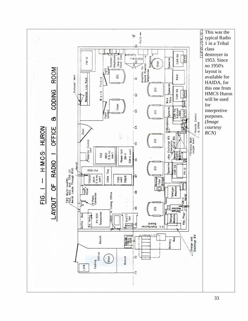
This was the
typical Radio
1 in a Tribal
class
destroyer in
1953. Since
no 1950's
layout is
available for
HAIDA, for
this one from
HMCS Huron
will be used
for
interpretive
purposes.
(Image
courtesy
RCN)
34
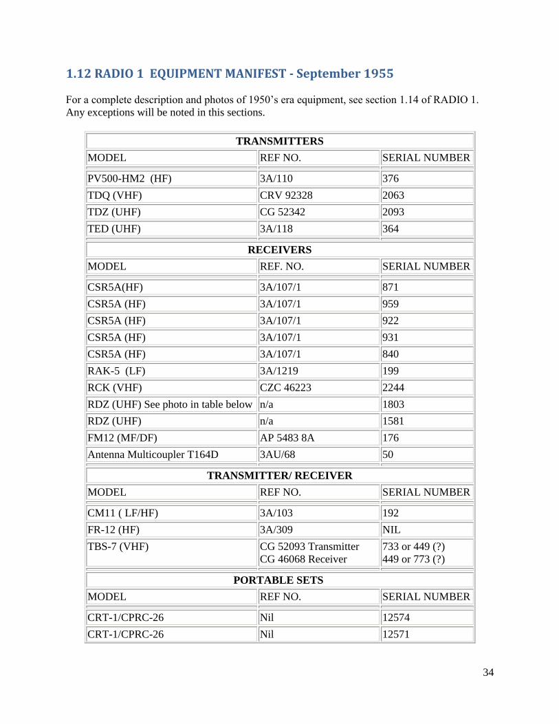
1.12 RADIO 1 EQUIPMENT MANIFEST - September 1955
For a complete description and photos of 1950’s era equipment, see section 1.14 of RADIO 1.
Any exceptions will be noted in this sections.
TRANSMITTERS
MODEL REF NO. SERIAL NUMBER
PV500-HM2 (HF) 3A/110 376
TDQ (VHF) CRV 92328 2063
TDZ (UHF) CG 52342 2093
TED (UHF) 3A/118 364
RECEIVERS
MODEL REF. NO. SERIAL NUMBER
CSR5A(HF) 3A/107/1 871
CSR5A (HF) 3A/107/1 959
CSR5A (HF) 3A/107/1 922
CSR5A (HF) 3A/107/1 931
CSR5A (HF) 3A/107/1 840
RAK-5 (LF) 3A/1219 199
RCK (VHF) CZC 46223 2244
RDZ (UHF) See photo in table below n/a 1803
RDZ (UHF) n/a 1581
FM12 (MF/DF) AP 5483 8A 176
Antenna Multicoupler T164D 3AU/68 50
TRANSMITTER/ RECEIVER
MODEL REF NO. SERIAL NUMBER
CM11 ( LF/HF) 3A/103 192
FR-12 (HF) 3A/309 NIL
TBS-7 (VHF) CG 52093 Transmitter
CG 46068 Receiver
733 or 449 (?)
449 or 773 (?)
PORTABLE SETS
MODEL REF NO. SERIAL NUMBER
CRT-1/CPRC-26 Nil 12574
CRT-1/CPRC-26 Nil 12571
35
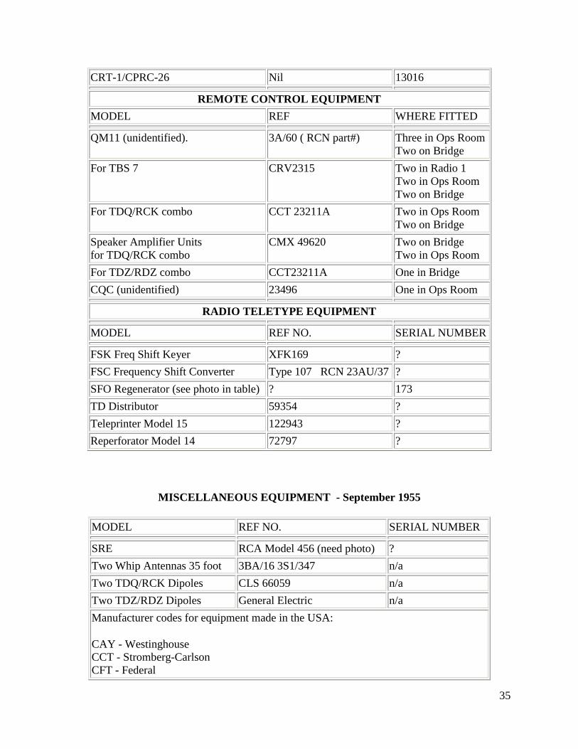
CRT-1/CPRC-26 Nil 13016
REMOTE CONTROL EQUIPMENT
MODEL REF WHERE FITTED
QM11 (unidentified). 3A/60 ( RCN part#) Three in Ops Room
Two on Bridge
For TBS 7 CRV2315 Two in Radio 1
Two in Ops Room
Two on Bridge
For TDQ/RCK combo CCT 23211A Two in Ops Room
Two on Bridge
Speaker Amplifier Units
for TDQ/RCK combo
CMX 49620 Two on Bridge
Two in Ops Room
For TDZ/RDZ combo CCT23211A One in Bridge
CQC (unidentified) 23496 One in Ops Room
RADIO TELETYPE EQUIPMENT
MODEL REF NO. SERIAL NUMBER
FSK Freq Shift Keyer XFK169 ?
FSC Frequency Shift Converter Type 107 RCN 23AU/37 ?
SFO Regenerator (see photo in table) ? 173
TD Distributor 59354 ?
Teleprinter Model 15 122943 ?
Reperforator Model 14 72797 ?
MISCELLANEOUS EQUIPMENT - September 1955
MODEL REF NO. SERIAL NUMBER
SRE RCA Model 456 (need photo) ?
Two Whip Antennas 35 foot 3BA/16 3S1/347 n/a
Two TDQ/RCK Dipoles CLS 66059 n/a
Two TDZ/RDZ Dipoles General Electric n/a
Manufacturer codes for equipment made in the USA:
CAY - Westinghouse
CCT - Stromberg-Carlson
CFT - Federal
36
CME - RME
CNA - National
CND - Andrea
CPN - Panoramic
CRV - RCA
CWQ - Wells Gardner
CZC - Scott
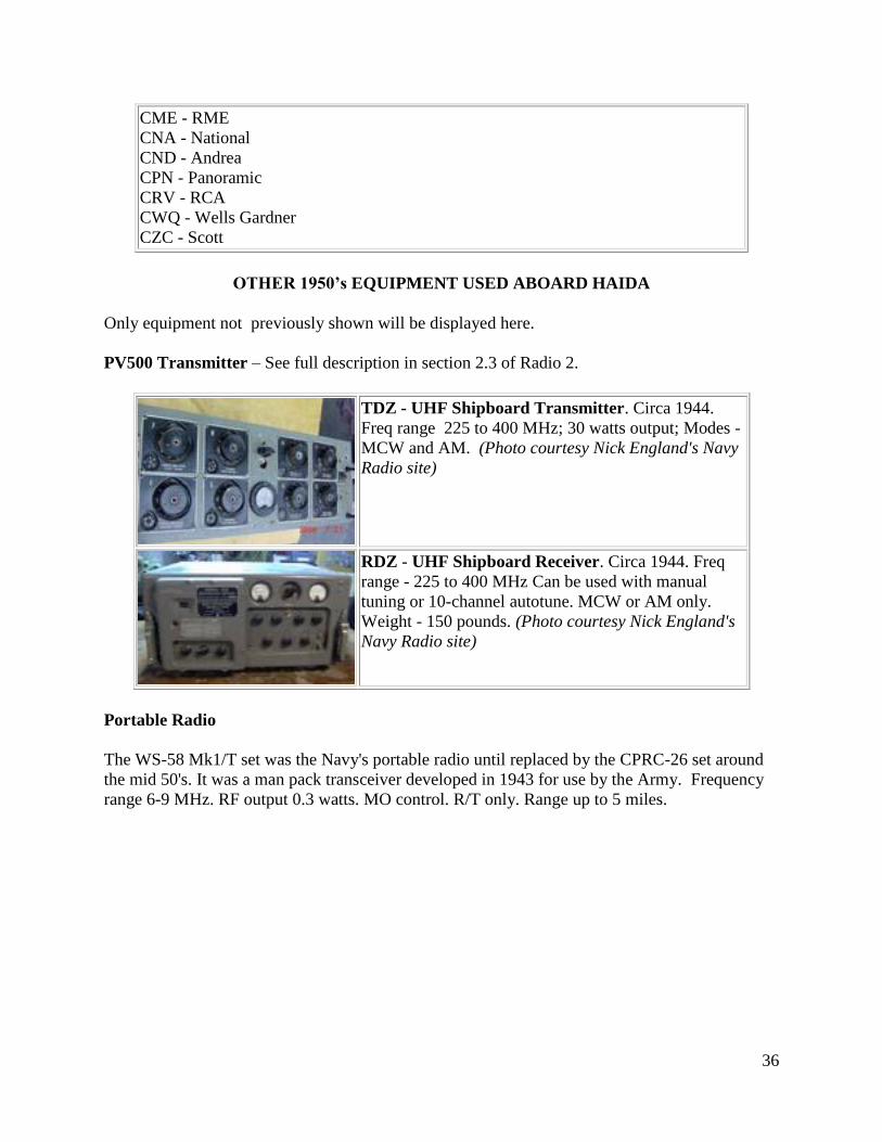
OTHER 1950’s EQUIPMENT USED ABOARD HAIDA
Only equipment not previously shown will be displayed here.
PV500 Transmitter – See full description in section 2.3 of Radio 2.
TDZ - UHF Shipboard Transmitter. Circa 1944.
Freq range 225 to 400 MHz; 30 watts output; Modes -
MCW and AM. (Photo courtesy Nick England's Navy
Radio site)
RDZ - UHF Shipboard Receiver. Circa 1944. Freq
range - 225 to 400 MHz Can be used with manual
tuning or 10-channel autotune. MCW or AM only.
Weight - 150 pounds. (Photo courtesy Nick England's
Navy Radio site)
Portable Radio
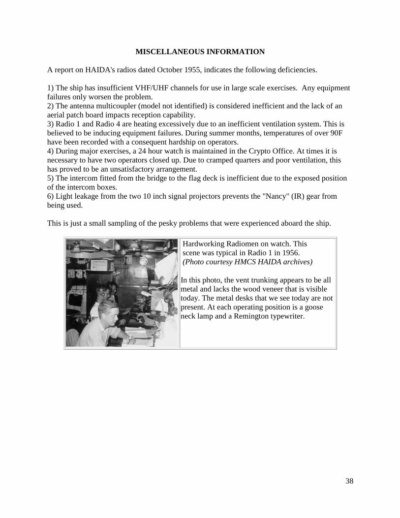
The WS-58 Mk1/T set was the Navy's portable radio until replaced by the CPRC-26 set around
the mid 50's. It was a man pack transceiver developed in 1943 for use by the Army. Frequency
range 6-9 MHz. RF output 0.3 watts. MO control. R/T only. Range up to 5 miles.
37
.
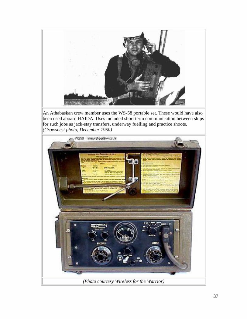
An Athabaskan crew member uses the WS-58 portable set. These would have also
been used aboard HAIDA. Uses included short term communication between ships
for such jobs as jack-stay transfers, underway fuelling and practice shoots.
(Crowsnest photo, December 1950)
(Photo courtesy Wireless for the Warrior)
38
MISCELLANEOUS INFORMATION
A report on HAIDA's radios dated October 1955, indicates the following deficiencies.
1) The ship has insufficient VHF/UHF channels for use in large scale exercises. Any equipment
failures only worsen the problem.
2) The antenna multicoupler (model not identified) is considered inefficient and the lack of an
aerial patch board impacts reception capability.
3) Radio 1 and Radio 4 are heating excessively due to an inefficient ventilation system. This is
believed to be inducing equipment failures. During summer months, temperatures of over 90F
have been recorded with a consequent hardship on operators.
4) During major exercises, a 24 hour watch is maintained in the Crypto Office. At times it is
necessary to have two operators closed up. Due to cramped quarters and poor ventilation, this
has proved to be an unsatisfactory arrangement.
5) The intercom fitted from the bridge to the flag deck is inefficient due to the exposed position
of the intercom boxes.
6) Light leakage from the two 10 inch signal projectors prevents the "Nancy" (IR) gear from
being used.
This is just a small sampling of the pesky problems that were experienced aboard the ship.
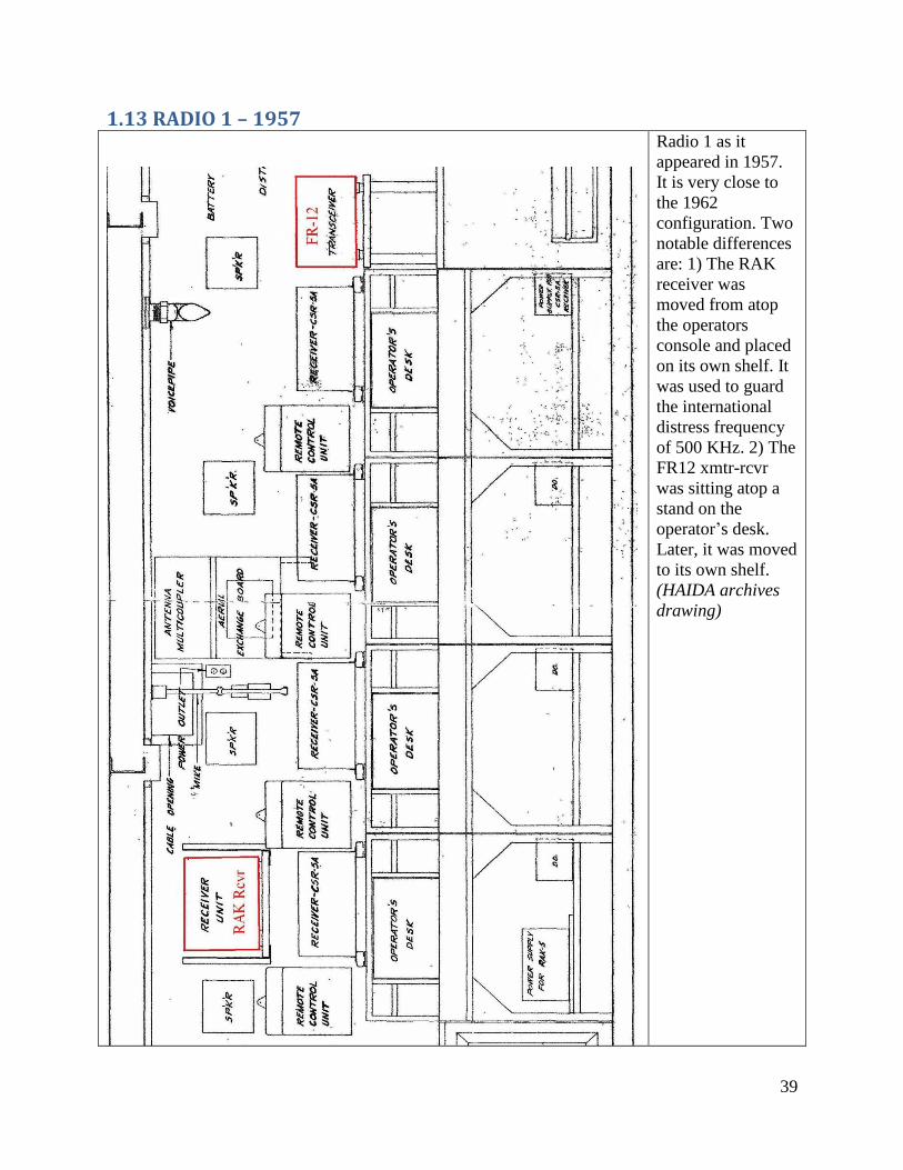
Hardworking Radiomen on watch. This
scene was typical in Radio 1 in 1956.
(Photo courtesy HMCS HAIDA archives)
In this photo, the vent trunking appears to be all
metal and lacks the wood veneer that is visible
today. The metal desks that we see today are not
present. At each operating position is a goose
neck lamp and a Remington typewriter.
39
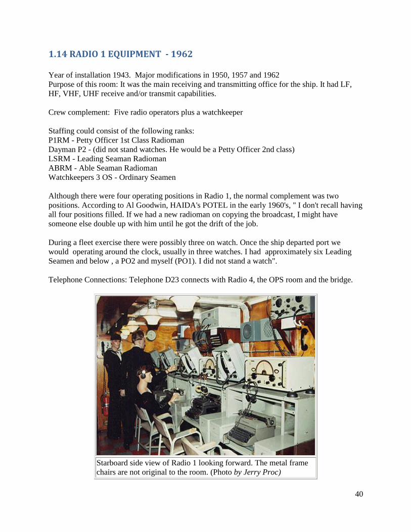
1.13 RADIO 1 – 1957
Radio 1 as it
appeared in 1957.
It is very close to
the 1962
configuration. Two
notable differences
are: 1) The RAK
receiver was
moved from atop
the operators
console and placed
on its own shelf. It
was used to guard
the international
distress frequency
of 500 KHz. 2) The
FR12 xmtr-rcvr
was sitting atop a
stand on the
operator’s desk.
Later, it was moved
to its own shelf.
(HAIDA archives
drawing)
40
1.14 RADIO 1 EQUIPMENT - 1962 Year of installation 1943. Major modifications in 1950, 1957 and 1962
Purpose of this room: It was the main receiving and transmitting office for the ship. It had LF,
HF, VHF, UHF receive and/or transmit capabilities.
Crew complement: Five radio operators plus a watchkeeper
Staffing could consist of the following ranks:
P1RM - Petty Officer 1st Class Radioman
Dayman P2 - (did not stand watches. He would be a Petty Officer 2nd class)
LSRM - Leading Seaman Radioman
ABRM - Able Seaman Radioman
Watchkeepers 3 OS - Ordinary Seamen
Although there were four operating positions in Radio 1, the normal complement was two
positions. According to Al Goodwin, HAIDA's POTEL in the early 1960's, " I don't recall having
all four positions filled. If we had a new radioman on copying the broadcast, I might have
someone else double up with him until he got the drift of the job.
During a fleet exercise there were possibly three on watch. Once the ship departed port we
would operating around the clock, usually in three watches. I had approximately six Leading
Seamen and below , a PO2 and myself (PO1). I did not stand a watch".
Telephone Connections: Telephone D23 connects with Radio 4, the OPS room and the bridge.
Starboard side view of Radio 1 looking forward. The metal frame
chairs are not original to the room. (Photo by Jerry Proc)
41
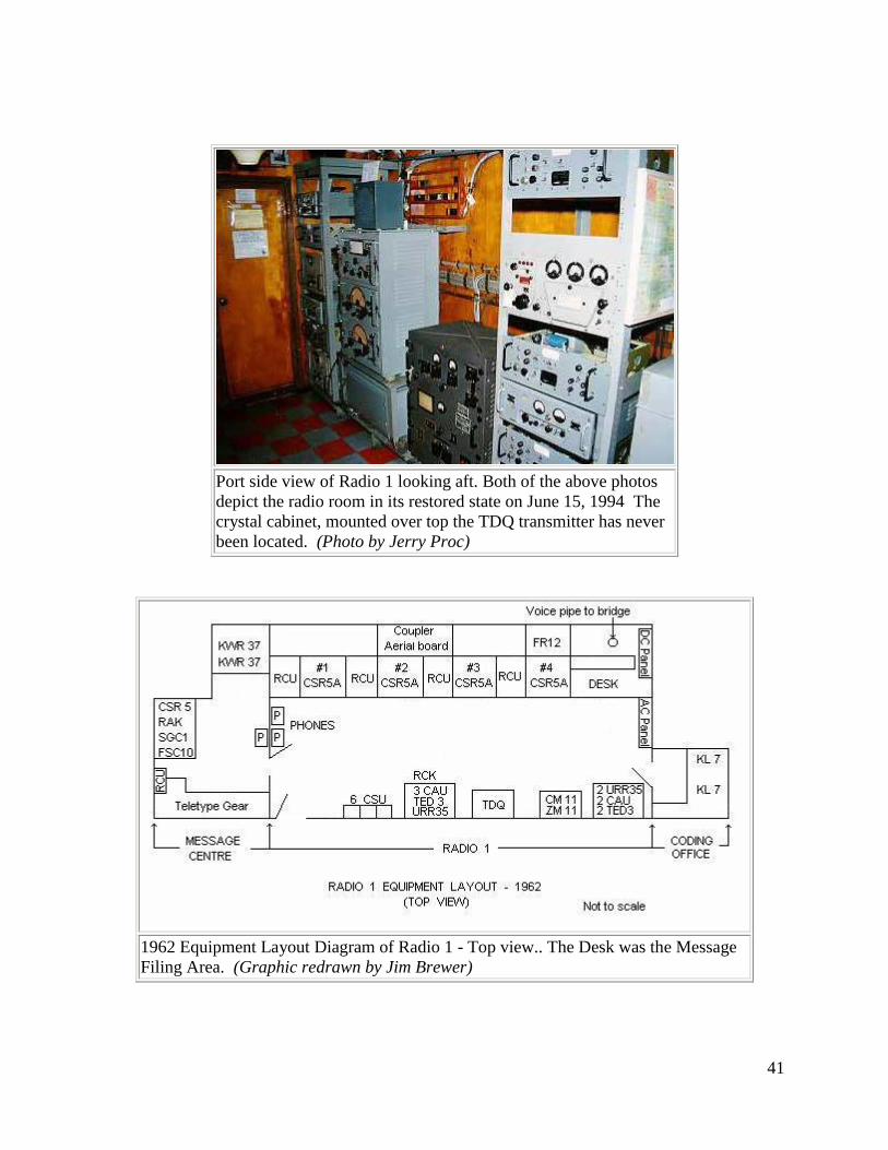
Port side view of Radio 1 looking aft. Both of the above photos
depict the radio room in its restored state on June 15, 1994 The
crystal cabinet, mounted over top the TDQ transmitter has never
been located. (Photo by Jerry Proc)
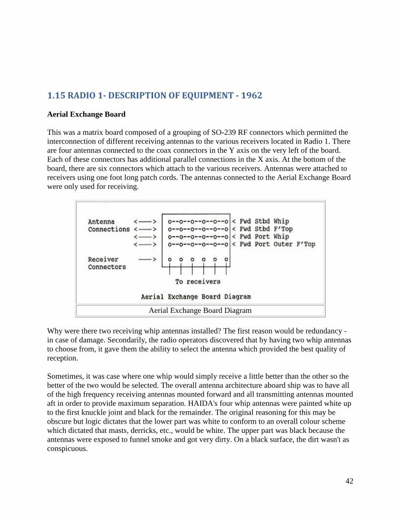
1962 Equipment Layout Diagram of Radio 1 - Top view.. The Desk was the Message
Filing Area. (Graphic redrawn by Jim Brewer)
42
1.15 RADIO 1- DESCRIPTION OF EQUIPMENT - 1962
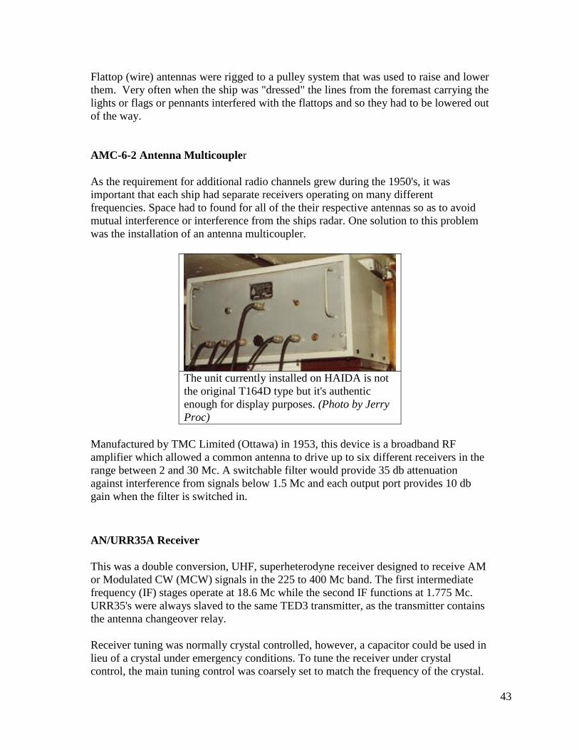
Aerial Exchange Board
This was a matrix board composed of a grouping of SO-239 RF connectors which permitted the
interconnection of different receiving antennas to the various receivers located in Radio 1. There
are four antennas connected to the coax connectors in the Y axis on the very left of the board.
Each of these connectors has additional parallel connections in the X axis. At the bottom of the
board, there are six connectors which attach to the various receivers. Antennas were attached to
receivers using one foot long patch cords. The antennas connected to the Aerial Exchange Board
were only used for receiving.
Aerial Exchange Board Diagram
Why were there two receiving whip antennas installed? The first reason would be redundancy -
in case of damage. Secondarily, the radio operators discovered that by having two whip antennas
to choose from, it gave them the ability to select the antenna which provided the best quality of
reception.
Sometimes, it was case where one whip would simply receive a little better than the other so the
better of the two would be selected. The overall antenna architecture aboard ship was to have all
of the high frequency receiving antennas mounted forward and all transmitting antennas mounted
aft in order to provide maximum separation. HAIDA's four whip antennas were painted white up
to the first knuckle joint and black for the remainder. The original reasoning for this may be
obscure but logic dictates that the lower part was white to conform to an overall colour scheme
which dictated that masts, derricks, etc., would be white. The upper part was black because the
antennas were exposed to funnel smoke and got very dirty. On a black surface, the dirt wasn't as
conspicuous.
43
Flattop (wire) antennas were rigged to a pulley system that was used to raise and lower
them. Very often when the ship was "dressed" the lines from the foremast carrying the
lights or flags or pennants interfered with the flattops and so they had to be lowered out
of the way.
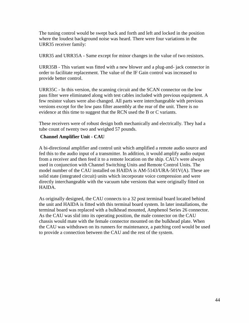
AMC-6-2 Antenna Multicoupler
As the requirement for additional radio channels grew during the 1950's, it was
important that each ship had separate receivers operating on many different
frequencies. Space had to found for all of the their respective antennas so as to avoid
mutual interference or interference from the ships radar. One solution to this problem
was the installation of an antenna multicoupler.
The unit currently installed on HAIDA is not
the original T164D type but it's authentic
enough for display purposes. (Photo by Jerry
Proc)
Manufactured by TMC Limited (Ottawa) in 1953, this device is a broadband RF
amplifier which allowed a common antenna to drive up to six different receivers in the
range between 2 and 30 Mc. A switchable filter would provide 35 db attenuation
against interference from signals below 1.5 Mc and each output port provides 10 db
gain when the filter is switched in.
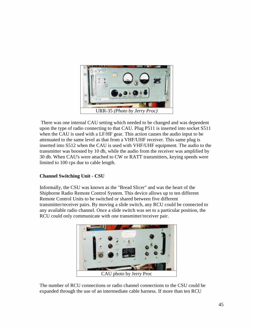
AN/URR35A Receiver
This was a double conversion, UHF, superheterodyne receiver designed to receive AM
or Modulated CW (MCW) signals in the 225 to 400 Mc band. The first intermediate
frequency (IF) stages operate at 18.6 Mc while the second IF functions at 1.775 Mc.
URR35's were always slaved to the same TED3 transmitter, as the transmitter contains
the antenna changeover relay.
Receiver tuning was normally crystal controlled, however, a capacitor could be used in
lieu of a crystal under emergency conditions. To tune the receiver under crystal
control, the main tuning control was coarsely set to match the frequency of the crystal.
44
The tuning control would be swept back and forth and left and locked in the position
where the loudest background noise was heard. There were four variations in the
URR35 receiver family:
URR35 and URR35A - Same except for minor changes in the value of two resistors.
URR35B - This variant was fitted with a new blower and a plug-and- jack connector in
order to facilitate replacement. The value of the IF Gain control was increased to
provide better control.
URR35C - In this version, the scanning circuit and the SCAN connector on the low
pass filter were eliminated along with test cables included with previous equipment. A
few resistor values were also changed. All parts were interchangeable with previous
versions except for the low pass filter assembly at the rear of the unit. There is no
evidence at this time to suggest that the RCN used the B or C variants.
These receivers were of robust design both mechanically and electrically. They had a
tube count of twenty two and weighed 57 pounds.
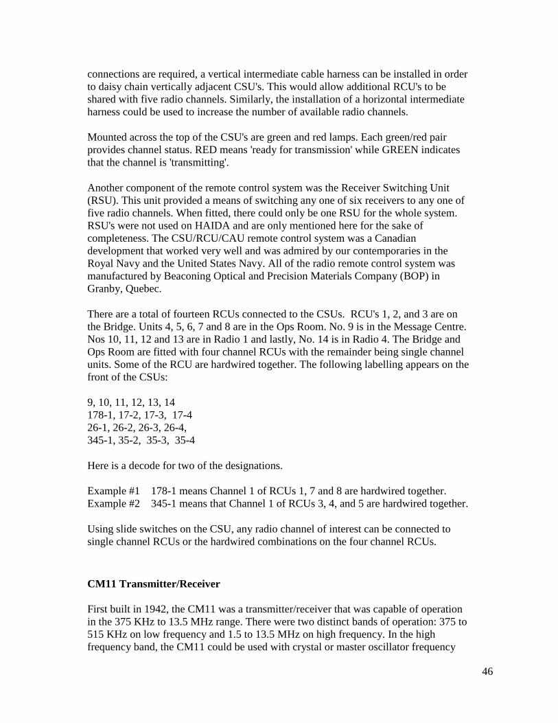
Channel Amplifier Unit - CAU
A bi-directional amplifier and control unit which amplified a remote audio source and
fed this to the audio input of a transmitter. In addition, it would amplify audio output
from a receiver and then feed it to a remote location on the ship. CAU's were always
used in conjunction with Channel Switching Units and Remote Control Units. The
model number of the CAU installed on HAIDA is AM-5143/URA-501V(A). These are
solid state (integrated circuit) units which incorporate voice compression and were
directly interchangeable with the vacuum tube versions that were originally fitted on
HAIDA.
As originally designed, the CAU connects to a 32 post terminal board located behind
the unit and HAIDA is fitted with this terminal board system. In later installations, the
terminal board was replaced with a bulkhead mounted, Amphenol Series 26 connector.
As the CAU was slid into its operating position, the male connector on the CAU
chassis would mate with the female connector mounted on the bulkhead plate. When
the CAU was withdrawn on its runners for maintenance, a patching cord would be used
to provide a connection between the CAU and the rest of the system.
45
URR-35 (Photo by Jerry Proc)
There was one internal CAU setting which needed to be changed and was dependent
upon the type of radio connecting to that CAU. Plug P511 is inserted into socket S511
when the CAU is used with a LF/HF gear. This action causes the audio input to be
attenuated to the same level as that from a VHF/UHF receiver. This same plug is
inserted into S512 when the CAU is used with VHF/UHF equipment. The audio to the
transmitter was boosted by 10 db, while the audio from the receiver was amplified by
30 db. When CAU's were attached to CW or RATT transmitters, keying speeds were
limited to 100 cps due to cable length.
Channel Switching Unit - CSU
Informally, the CSU was known as the "Bread Slicer" and was the heart of the
Shipborne Radio Remote Control System. This device allows up to ten different
Remote Control Units to be switched or shared between five different
transmitter/receiver pairs. By moving a slide switch, any RCU could be connected to
any available radio channel. Once a slide switch was set to a particular position, the
RCU could only communicate with one transmitter/receiver pair.
CAU photo by Jerry Proc
The number of RCU connections or radio channel connections to the CSU could be
expanded through the use of an intermediate cable harness. If more than ten RCU
46
connections are required, a vertical intermediate cable harness can be installed in order
to daisy chain vertically adjacent CSU's. This would allow additional RCU's to be
shared with five radio channels. Similarly, the installation of a horizontal intermediate
harness could be used to increase the number of available radio channels.
Mounted across the top of the CSU's are green and red lamps. Each green/red pair
provides channel status. RED means 'ready for transmission' while GREEN indicates
that the channel is 'transmitting'.
Another component of the remote control system was the Receiver Switching Unit
(RSU). This unit provided a means of switching any one of six receivers to any one of
five radio channels. When fitted, there could only be one RSU for the whole system.
RSU's were not used on HAIDA and are only mentioned here for the sake of
completeness. The CSU/RCU/CAU remote control system was a Canadian
development that worked very well and was admired by our contemporaries in the
Royal Navy and the United States Navy. All of the radio remote control system was
manufactured by Beaconing Optical and Precision Materials Company (BOP) in
Granby, Quebec.
There are a total of fourteen RCUs connected to the CSUs. RCU's 1, 2, and 3 are on
the Bridge. Units 4, 5, 6, 7 and 8 are in the Ops Room. No. 9 is in the Message Centre.
Nos 10, 11, 12 and 13 are in Radio 1 and lastly, No. 14 is in Radio 4. The Bridge and
Ops Room are fitted with four channel RCUs with the remainder being single channel
units. Some of the RCU are hardwired together. The following labelling appears on the
front of the CSUs:
9, 10, 11, 12, 13, 14
178-1, 17-2, 17-3, 17-4
26-1, 26-2, 26-3, 26-4,
345-1, 35-2, 35-3, 35-4
Here is a decode for two of the designations.
Example #1 178-1 means Channel 1 of RCUs 1, 7 and 8 are hardwired together.
Example #2 345-1 means that Channel 1 of RCUs 3, 4, and 5 are hardwired together.
Using slide switches on the CSU, any radio channel of interest can be connected to
single channel RCUs or the hardwired combinations on the four channel RCUs.
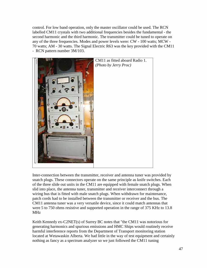
CM11 Transmitter/Receiver
First built in 1942, the CM11 was a transmitter/receiver that was capable of operation
in the 375 KHz to 13.5 MHz range. There were two distinct bands of operation: 375 to
515 KHz on low frequency and 1.5 to 13.5 MHz on high frequency. In the high
frequency band, the CM11 could be used with crystal or master oscillator frequency
47
control. For low band operation, only the master oscillator could be used. The RCN
labelled CM11 crystals with two additional frequencies besides the fundamental - the
second harmonic and the third harmonic. The transmitter could be tuned to operate on
any of the three frequencies. Modes and power levels were: CW - 100 watts; MCW -
70 watts; AM - 30 watts. The Signal Electric R63 was the key provided with the CM11
- RCN pattern number 3M/103.
CM11 as fitted aboard Radio 1.
(Photo by Jerry Proc)
Inter-connection between the transmitter, receiver and antenna tuner was provided by
snatch plugs. These connectors operate on the same principle as knife switches. Each
of the three slide out units in the CM11 are equipped with female snatch plugs. When
slid into place, the antenna tuner, transmitter and receiver interconnect through a
wiring bus that is fitted with male snatch plugs. When withdrawn for maintenance,
patch cords had to be installed between the transmitter or receiver and the bus. The
CM11 antenna tuner was a very versatile device, since it could match antennas that
were 5 to 750 ohms resistive and supported operation in the range of 375 KHz to 13.8
MHz
Keith Kennedy ex-C2NET(s) of Surrey BC notes that "the CM11 was notorious for
generating harmonics and spurious emissions and HMC Ships would routinely receive
harmful interference reports from the Department of Transport monitoring station
located at Wetawaskin Alberta. We had little in the way of test equipment and certainly
nothing as fancy as a spectrum analyzer so we just followed the CM11 tuning
48
instructions and filed the reports away. The CM11 was also known for its chirpy CW
signal when controlled by the master oscillator but it behaved properly under crystal
control. CM11's also had a bad habit becoming detuned as the ship rolled. It was the
result of changing capacitance between the antenna and the surface of the sea".
On HAIDA's bridge, an SM11 remote radio telephone control unit can still be seen. It
was abandoned after the RCU/CSU/CAU radio remote control system was installed.
All of the CM11's fitted on HAIDA were connected to the Shipborne Remote Control
System and were keyed or controlled by the RCU's.
The power supply for the CM11 was very versatile, as it could operate on 120/220
VAC or 24/36/220 VDC power sources. A fifteen second time delay circuit prevented
power from being applied to the transmitter in order to protect the mercury vapour
rectifiers. There was an emergency mode which decreased the time delay to 4 seconds
but at the expense of shorter mercury rectifier life. Weighing in around 478 pounds, the
CM11 just wasn't portable! Eventually, the CM11 was superseded by the AN/URC32
transceiver.
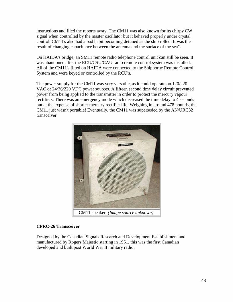
CM11 speaker. (Image source unknown)
CPRC-26 Transceiver
Designed by the Canadian Signals Research and Development Establishment and
manufactured by Rogers Majestic starting in 1951, this was the first Canadian
developed and built post World War II military radio.
49
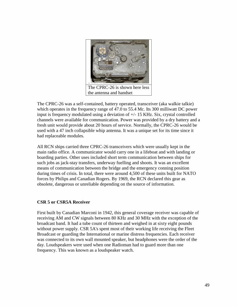
.
The CPRC-26 is shown here less
the antenna and handset
The CPRC-26 was a self-contained, battery operated, transceiver (aka walkie talkie)
which operates in the frequency range of 47.0 to 55.4 Mc. Its 300 milliwatt DC power
input is frequency modulated using a deviation of +/- 15 KHz. Six, crystal controlled
channels were available for communication. Power was provided by a dry battery and a
fresh unit would provide about 20 hours of service. Normally, the CPRC-26 would be
used with a 47 inch collapsible whip antenna. It was a unique set for its time since it
had replaceable modules.
All RCN ships carried three CPRC-26 transceivers which were usually kept in the
main radio office. A communicator would carry one in a lifeboat and with landing or
boarding parties. Other uses included short term communication between ships for
such jobs as jack-stay transfers, underway fuelling and shoots. It was an excellent
means of communication between the bridge and the emergency conning position
during times of crisis. In total, there were around 4,500 of these units built for NATO
forces by Philips and Canadian Rogers. By 1969, the RCN declared this gear as
obsolete, dangerous or unreliable depending on the source of information.
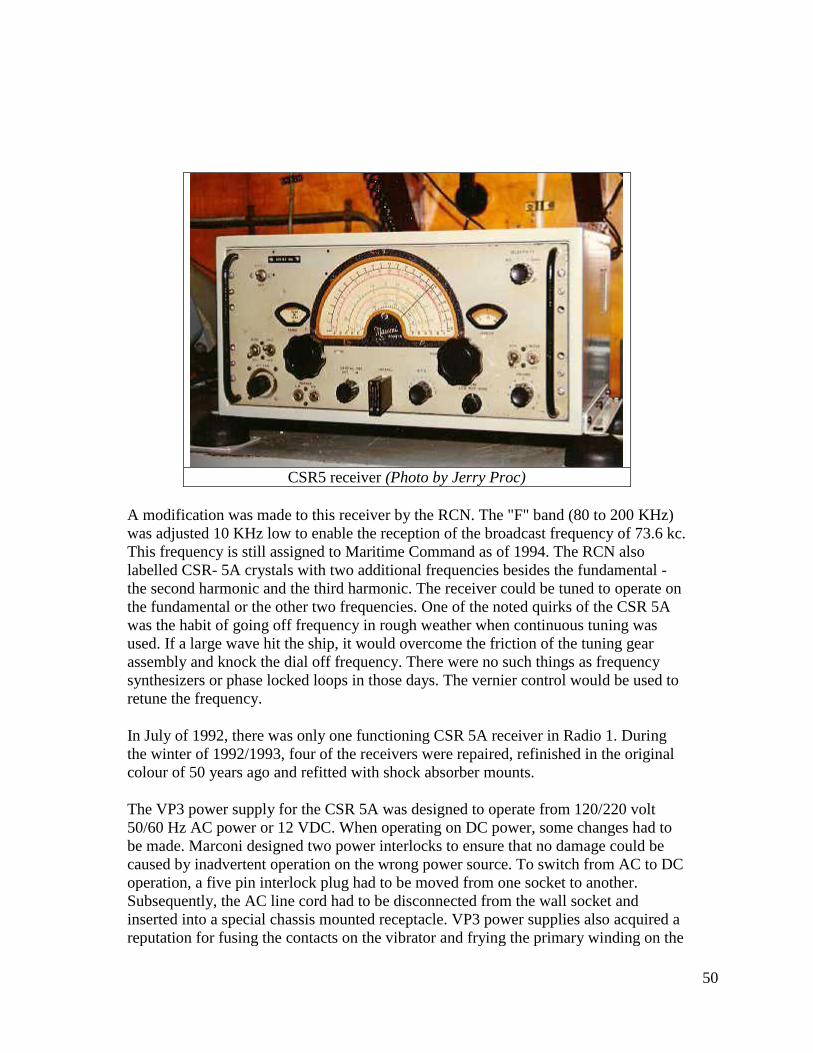
CSR 5 or CSR5A Receiver
First built by Canadian Marconi in 1942, this general coverage receiver was capable of
receiving AM and CW signals between 80 KHz and 30 MHz with the exception of the
broadcast band. It had a tube count of thirteen and weighed in at sixty eight pounds
without power supply. CSR 5A's spent most of their working life receiving the Fleet
Broadcast or guarding the International or marine distress frequencies. Each receiver
was connected to its own wall mounted speaker, but headphones were the order of the
day. Loudspeakers were used when one Radioman had to guard more than one
frequency. This was known as a loudspeaker watch.
50
CSR5 receiver (Photo by Jerry Proc)
A modification was made to this receiver by the RCN. The "F" band (80 to 200 KHz)
was adjusted 10 KHz low to enable the reception of the broadcast frequency of 73.6 kc.
This frequency is still assigned to Maritime Command as of 1994. The RCN also
labelled CSR- 5A crystals with two additional frequencies besides the fundamental -
the second harmonic and the third harmonic. The receiver could be tuned to operate on
the fundamental or the other two frequencies. One of the noted quirks of the CSR 5A
was the habit of going off frequency in rough weather when continuous tuning was
used. If a large wave hit the ship, it would overcome the friction of the tuning gear
assembly and knock the dial off frequency. There were no such things as frequency
synthesizers or phase locked loops in those days. The vernier control would be used to
retune the frequency.
In July of 1992, there was only one functioning CSR 5A receiver in Radio 1. During
the winter of 1992/1993, four of the receivers were repaired, refinished in the original
colour of 50 years ago and refitted with shock absorber mounts.
The VP3 power supply for the CSR 5A was designed to operate from 120/220 volt
50/60 Hz AC power or 12 VDC. When operating on DC power, some changes had to
be made. Marconi designed two power interlocks to ensure that no damage could be
caused by inadvertent operation on the wrong power source. To switch from AC to DC
operation, a five pin interlock plug had to be moved from one socket to another.
Subsequently, the AC line cord had to be disconnected from the wall socket and
inserted into a special chassis mounted receptacle. VP3 power supplies also acquired a
reputation for fusing the contacts on the vibrator and frying the primary winding on the
51
power transformer. By 1969, the CSR 5A was considered obsolete and was taken out
of service.
In July of 1992, there was only one VP3 supply among four CSR 5A receivers aboard
HAIDA. Another VP3 was found in storage but was completely deteriorated and had to
be rebuilt from bare metal. Since three other VP3 power supplies were missing, near
replicas were constructed in order to restore operation to the receivers.
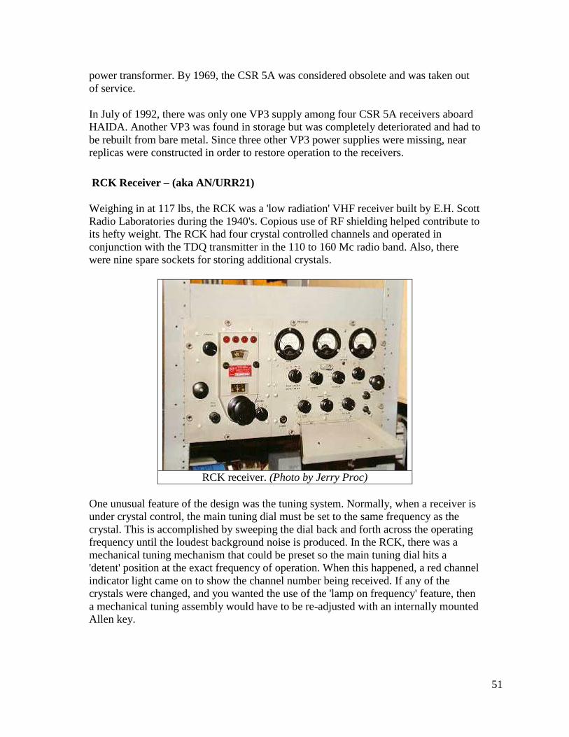
RCK Receiver – (aka AN/URR21)
Weighing in at 117 lbs, the RCK was a 'low radiation' VHF receiver built by E.H. Scott
Radio Laboratories during the 1940's. Copious use of RF shielding helped contribute to
its hefty weight. The RCK had four crystal controlled channels and operated in
conjunction with the TDQ transmitter in the 110 to 160 Mc radio band. Also, there
were nine spare sockets for storing additional crystals.
RCK receiver. (Photo by Jerry Proc)
One unusual feature of the design was the tuning system. Normally, when a receiver is
under crystal control, the main tuning dial must be set to the same frequency as the
crystal. This is accomplished by sweeping the dial back and forth across the operating
frequency until the loudest background noise is produced. In the RCK, there was a
mechanical tuning mechanism that could be preset so the main tuning dial hits a
'detent' position at the exact frequency of operation. When this happened, a red channel
indicator light came on to show the channel number being received. If any of the
crystals were changed, and you wanted the use of the 'lamp on frequency' feature, then
a mechanical tuning assembly would have to be re-adjusted with an internally mounted
Allen key.
52
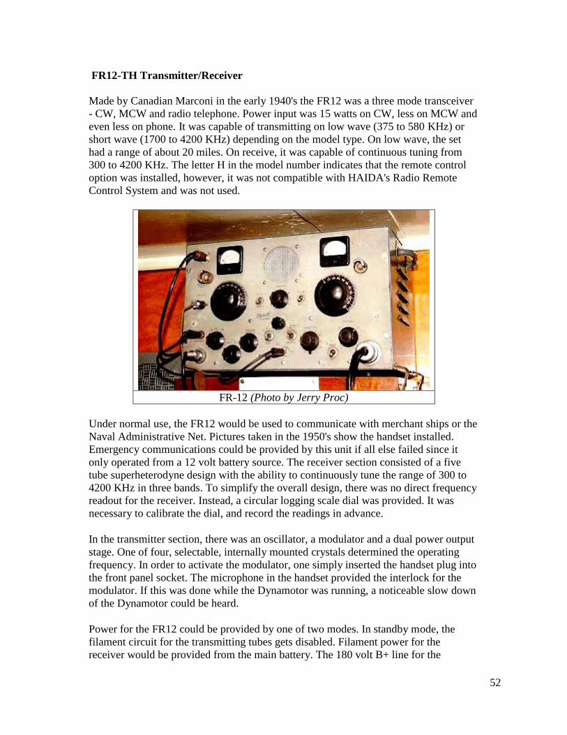
FR12-TH Transmitter/Receiver
Made by Canadian Marconi in the early 1940's the FR12 was a three mode transceiver
- CW, MCW and radio telephone. Power input was 15 watts on CW, less on MCW and
even less on phone. It was capable of transmitting on low wave (375 to 580 KHz) or
short wave (1700 to 4200 KHz) depending on the model type. On low wave, the set
had a range of about 20 miles. On receive, it was capable of continuous tuning from
300 to 4200 KHz. The letter H in the model number indicates that the remote control
option was installed, however, it was not compatible with HAIDA's Radio Remote
Control System and was not used.
FR-12 (Photo by Jerry Proc)
Under normal use, the FR12 would be used to communicate with merchant ships or the
Naval Administrative Net. Pictures taken in the 1950's show the handset installed.
Emergency communications could be provided by this unit if all else failed since it
only operated from a 12 volt battery source. The receiver section consisted of a five
tube superheterodyne design with the ability to continuously tune the range of 300 to
4200 KHz in three bands. To simplify the overall design, there was no direct frequency
readout for the receiver. Instead, a circular logging scale dial was provided. It was
necessary to calibrate the dial, and record the readings in advance.
In the transmitter section, there was an oscillator, a modulator and a dual power output
stage. One of four, selectable, internally mounted crystals determined the operating
frequency. In order to activate the modulator, one simply inserted the handset plug into
the front panel socket. The microphone in the handset provided the interlock for the
modulator. If this was done while the Dynamotor was running, a noticeable slow down
of the Dynamotor could be heard.
Power for the FR12 could be provided by one of two modes. In standby mode, the
filament circuit for the transmitting tubes gets disabled. Filament power for the
receiver would be provided from the main battery. The 180 volt B+ line for the
53
receiver would be furnished from four, external, 45 volt dry batteries wired in series.
Standby mode would dramatically increase the life of the main battery. In normal
mode, all power for the receiver and transmitter was provided by the main battery. An
internal Dynamotor produced high tension for the transmitter but it had to be inspected
after every 500 hours of operation. Input power to the FR12 was 12 volts DC at 6 amps
on receive and 13 amps on transmit when used in normal mode. On HAIDA, the
antenna for the FR12 was a sloping, twenty seven foot vertical wire designated as the
Port Outer Vertical.
Al Goodwin of Dartmouth N.S. did some range experiments with the FR12. "It was
sent away in a sea boat on a couple of occasions. In those days, we didn't have
commercial mobile antennas available to us, so we rigged up a 35 foot wire whip
antenna. The exercise was not deemed a success as we lost communications around
five miles. On HAIDA, we used this set for both AM and CW communications. For
CW operation, we would have to attach a key with a very long lead. In an unusual case,
the late Keith Lake (VE1PX) used the FR12 to modulate the Marconi PV500 thus
giving it AM capability for use on the amateur bands. He put out quite a strong signal
compared to the 30 watts of the Marconi CM11".
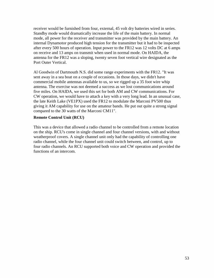
Remote Control Unit (RCU)
This was a device that allowed a radio channel to be controlled from a remote location
on the ship. RCU's come in single channel and four channel versions, with and without
weatherproof covers. A single channel unit only had the capability of controlling one
radio channel, while the four channel unit could switch between, and control, up to
four radio channels. An RCU supported both voice and CW operation and provided the
functions of an intercom.
54
RCU (Photo by Jerry Proc)_
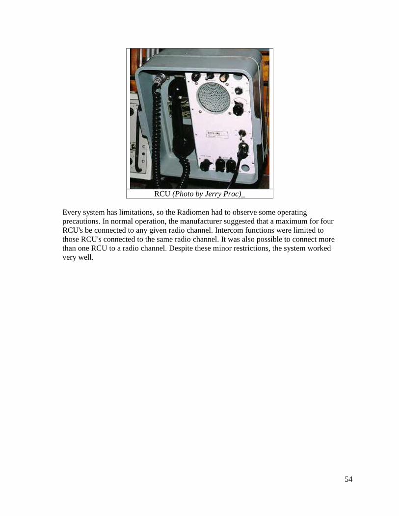
Every system has limitations, so the Radiomen had to observe some operating
precautions. In normal operation, the manufacturer suggested that a maximum for four
RCU's be connected to any given radio channel. Intercom functions were limited to
those RCU's connected to the same radio channel. It was also possible to connect more
than one RCU to a radio channel. Despite these minor restrictions, the system worked
very well.
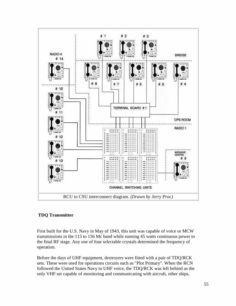
55
RCU to CSU interconnect diagram. (Drawn by Jerry Proc)
TDQ Transmitter
First built for the U.S. Navy in May of 1943, this unit was capable of voice or MCW
transmissions in the 115 to 156 Mc band while running 45 watts continuous power to
the final RF stage. Any one of four selectable crystals determined the frequency of
operation.
Before the days of UHF equipment, destroyers were fitted with a pair of TDQ/RCK
sets. These were used for operations circuits such as "Plot Primary". When the RCN
followed the United States Navy to UHF voice, the TDQ/RCK was left behind as the
only VHF set capable of monitoring and communicating with aircraft, other ships,
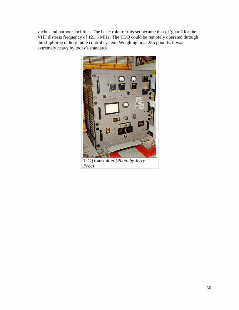
56
yachts and harbour facilities. The basic role for this set became that of 'guard' for the
VHF distress frequency of 121.5 MHz. The TDQ could be remotely operated through
the shipborne radio remote control system. Weighing in at 285 pounds, it was
extremely heavy by today's standards
TDQ transmitter (Photo by Jerry
Proc)
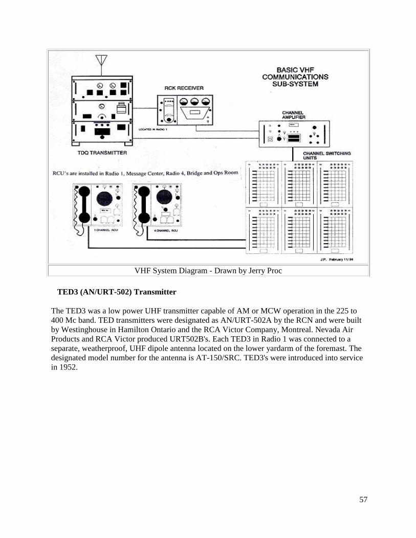
57
VHF System Diagram - Drawn by Jerry Proc
TED3 (AN/URT-502) Transmitter
The TED3 was a low power UHF transmitter capable of AM or MCW operation in the 225 to
400 Mc band. TED transmitters were designated as AN/URT-502A by the RCN and were built
by Westinghouse in Hamilton Ontario and the RCA Victor Company, Montreal. Nevada Air
Products and RCA Victor produced URT502B's. Each TED3 in Radio 1 was connected to a
separate, weatherproof, UHF dipole antenna located on the lower yardarm of the foremast. The
designated model number for the antenna is AT-150/SRC. TED3's were introduced into service
in 1952.
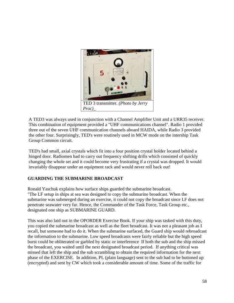
58
TED 3 transmitter. (Photo by Jerry
Proc)_
A TED3 was always used in conjunction with a Channel Amplifier Unit and a URR35 receiver.
This combination of equipment provided a "UHF communications channel". Radio 1 provided
three out of the seven UHF communication channels aboard HAIDA, while Radio 3 provided
the other four. Surprisingly, TED's were routinely used in MCW mode on the intership Task
Group Common circuit.
TED's had small, axial crystals which fit into a four position crystal holder located behind a
hinged door. Radiomen had to carry out frequency shifting drills which consisted of quickly
changing the whole set and it could become very frustrating if a crystal was dropped. It would
invariably disappear under an equipment rack and would never roll back out!
GUARDING THE SUBMARINE BROADCAST
Ronald Yaschuk explains how surface ships guarded the submarine broadcast.
"The LF setup in ships at sea was designed to copy the submarine broadcast. When the
submarine was submerged during an exercise, it could not copy the broadcast since LF does not
penetrate seawater very far. Hence, the Commander of the Task Force, Task Group etc.,
designated one ship as SUBMARINE GUARD.
This was also laid out in the OPORDER Exercise Book. If your ship was tasked with this duty,
you copied the submarine broadcast as well as the fleet broadcast. It was not a pleasant job as I
recall, but someone had to do it. When the submarine surfaced, the Guard ship would rebroadcast
the information to the submarine. Low speed broadcasts were fairly reliable but the high speed
burst could be obliterated or garbled by static or interference If both the sub and the ship missed
the broadcast, you waited until the next designated broadcast period. If anything critical was
missed that left the ship and the sub scrambling to obtain the required information for the next
phase of the EXERCISE. In addition, PL (plain language) sent to the sub had to be buttoned up
(encrypted) and sent by CW which took a considerable amount of time. Some of the traffic for
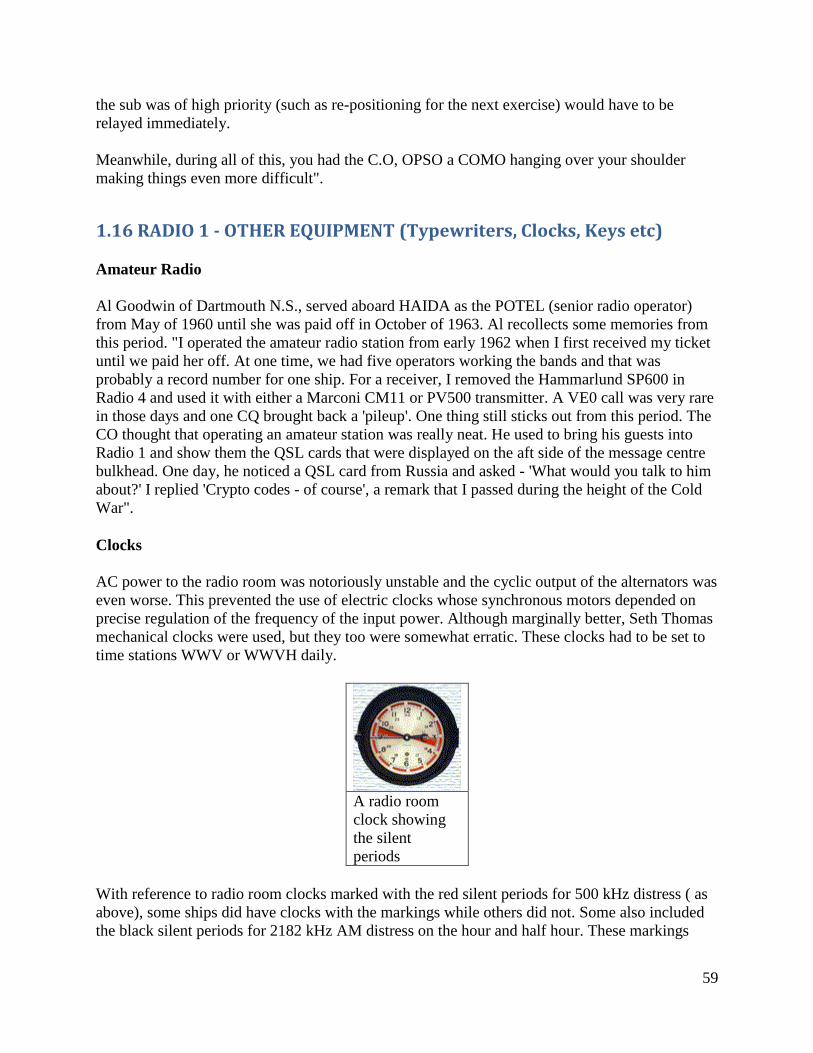
59
the sub was of high priority (such as re-positioning for the next exercise) would have to be
relayed immediately.
Meanwhile, during all of this, you had the C.O, OPSO a COMO hanging over your shoulder
making things even more difficult".
1.16 RADIO 1 - OTHER EQUIPMENT (Typewriters, Clocks, Keys etc)
Amateur Radio
Al Goodwin of Dartmouth N.S., served aboard HAIDA as the POTEL (senior radio operator)
from May of 1960 until she was paid off in October of 1963. Al recollects some memories from
this period. "I operated the amateur radio station from early 1962 when I first received my ticket
until we paid her off. At one time, we had five operators working the bands and that was
probably a record number for one ship. For a receiver, I removed the Hammarlund SP600 in
Radio 4 and used it with either a Marconi CM11 or PV500 transmitter. A VE0 call was very rare
in those days and one CQ brought back a 'pileup'. One thing still sticks out from this period. The
CO thought that operating an amateur station was really neat. He used to bring his guests into
Radio 1 and show them the QSL cards that were displayed on the aft side of the message centre
bulkhead. One day, he noticed a QSL card from Russia and asked - 'What would you talk to him
about?' I replied 'Crypto codes - of course', a remark that I passed during the height of the Cold
War".
Clocks
AC power to the radio room was notoriously unstable and the cyclic output of the alternators was
even worse. This prevented the use of electric clocks whose synchronous motors depended on
precise regulation of the frequency of the input power. Although marginally better, Seth Thomas
mechanical clocks were used, but they too were somewhat erratic. These clocks had to be set to
time stations WWV or WWVH daily.
A radio room
clock showing
the silent
periods
With reference to radio room clocks marked with the red silent periods for 500 kHz distress ( as
above), some ships did have clocks with the markings while others did not. Some also included
the black silent periods for 2182 kHz AM distress on the hour and half hour. These markings
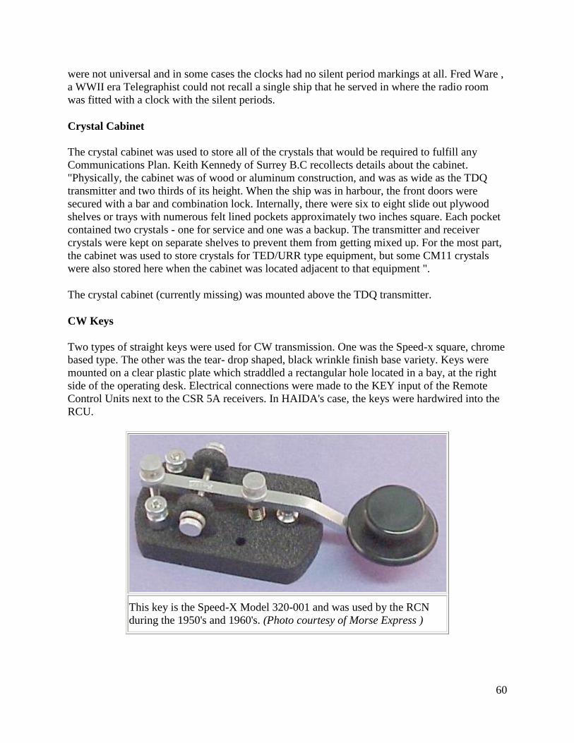
60
were not universal and in some cases the clocks had no silent period markings at all. Fred Ware ,
a WWII era Telegraphist could not recall a single ship that he served in where the radio room
was fitted with a clock with the silent periods.
Crystal Cabinet
The crystal cabinet was used to store all of the crystals that would be required to fulfill any
Communications Plan. Keith Kennedy of Surrey B.C recollects details about the cabinet.
"Physically, the cabinet was of wood or aluminum construction, and was as wide as the TDQ
transmitter and two thirds of its height. When the ship was in harbour, the front doors were
secured with a bar and combination lock. Internally, there were six to eight slide out plywood
shelves or trays with numerous felt lined pockets approximately two inches square. Each pocket
contained two crystals - one for service and one was a backup. The transmitter and receiver
crystals were kept on separate shelves to prevent them from getting mixed up. For the most part,
the cabinet was used to store crystals for TED/URR type equipment, but some CM11 crystals
were also stored here when the cabinet was located adjacent to that equipment ".
The crystal cabinet (currently missing) was mounted above the TDQ transmitter.
CW Keys
Two types of straight keys were used for CW transmission. One was the Speed-x square, chrome
based type. The other was the tear- drop shaped, black wrinkle finish base variety. Keys were
mounted on a clear plastic plate which straddled a rectangular hole located in a bay, at the right
side of the operating desk. Electrical connections were made to the KEY input of the Remote
Control Units next to the CSR 5A receivers. In HAIDA's case, the keys were hardwired into the
RCU.
This key is the Speed-X Model 320-001 and was used by the RCN
during the 1950's and 1960's. (Photo courtesy of Morse Express )
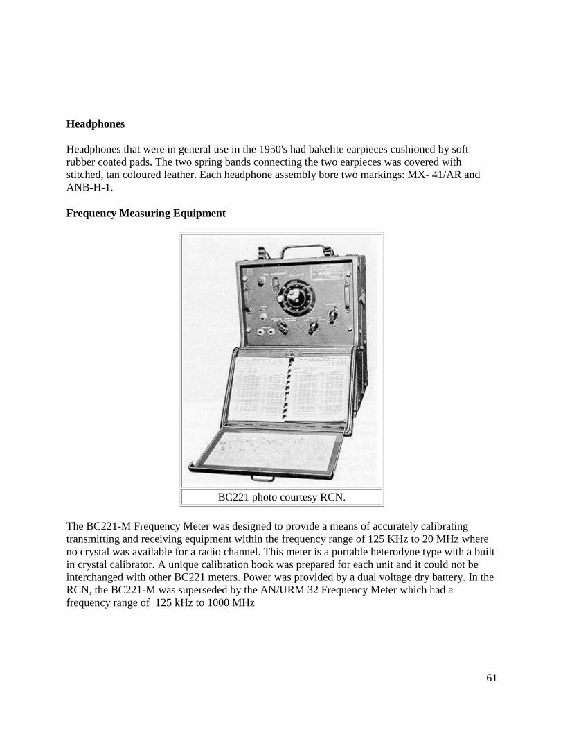
61
Headphones
Headphones that were in general use in the 1950's had bakelite earpieces cushioned by soft
rubber coated pads. The two spring bands connecting the two earpieces was covered with
stitched, tan coloured leather. Each headphone assembly bore two markings: MX- 41/AR and
ANB-H-1.
Frequency Measuring Equipment
BC221 photo courtesy RCN.
The BC221-M Frequency Meter was designed to provide a means of accurately calibrating
transmitting and receiving equipment within the frequency range of 125 KHz to 20 MHz where
no crystal was available for a radio channel. This meter is a portable heterodyne type with a built
in crystal calibrator. A unique calibration book was prepared for each unit and it could not be
interchanged with other BC221 meters. Power was provided by a dual voltage dry battery. In the
RCN, the BC221-M was superseded by the AN/URM 32 Frequency Meter which had a
frequency range of 125 kHz to 1000 MHz
62
Metal Desks and Chairs
Metal desks that were used for the four operating consoles were supplied by Eaton's of Canada
but it is not known whether they could be purchased by the general public. The original colour is
a metallic flake green finish as evidenced by looking underneath some of the sliding typewriter
trays. Over the years, the desks have been repainted in navy grey.
Gregory McLean of Abbotsford B.C. recalls, with great detail, the furnishings and the some of
the routines in Radio 1. "The chairs used in some radio rooms of the 1950's were swivelling arm
chairs. They were of robust construction, with padded backs and tubular sides. The bases of these
chairs were bolted to the deck and a pivoting steel shaft was affixed to the underside of the seat.
This shaft was fitted into the base, thus giving the chair firm support and allowing the operator to
swivel 360 degrees. This type of seating arrangement persisted in some ships and is still in use
today.
To a great extent, it was felt that the swivel chair was superior to the 'chair and chain' technique
which was used on HAIDA at the time of her de-commissioning. The tubular sides and the
anchored base gave firm support in rough seas and was easy to use. On the chained chairs, the
chair did not move once the chain was secured making it difficult to get ones legs out from under
the desk.
Decks on ships were scrubbed every day, but special house cleaning was done for Captain's
rounds. Radio 1 "scrub out" was in the middle or morning watch when the radio traffic volume
was least. At that time, the swivel chairs were pulled from their bases and set to one side. The
'broadcast' chair was left to last in case traffic resumed".
When seamen were not on radio watch, spare hours were filled with maintenance, book
amendments, cleaning stations and working part ship (painting, scraping etc).
Telegraphic Typewriters
The typewriters used at the operating consoles were Royal or Remington Telegraphic typewriters
which could only print capital letters and some special symbols. Two keys away, and to the right
of the letter L was a "dead" key which would print a line and then, without the carriage moving,
the operator could type an accented or Tiddley" (special) letter.
They were of the closed frame variety and painted in wrinkle finish grey. The typewriter itself,
was bolted to a sliding tray which was located in the middle bay of the desk. Radiomen often
referred to the typewriters as "mills". In those days, the Royal or Remington typewriters looked
sleek and modern.
Often, an operator would spend long hours in continuous copy. In order to make life more
comfortable, he would pull the pins that restrained the typewriter tray and move the tray out and
slightly down. Everything worked fine until a large wave hit the ship and in turn, it would cause
the typewriter to jump forward and unto the operators lap, often with undesirable results. The
unfortunate operator might be talking with a slightly high pitched voice for a while. The paper
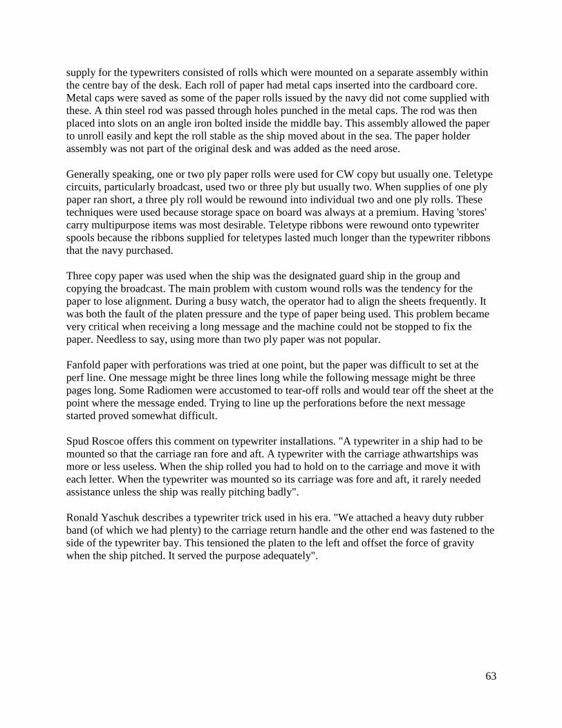
63
supply for the typewriters consisted of rolls which were mounted on a separate assembly within
the centre bay of the desk. Each roll of paper had metal caps inserted into the cardboard core.
Metal caps were saved as some of the paper rolls issued by the navy did not come supplied with
these. A thin steel rod was passed through holes punched in the metal caps. The rod was then
placed into slots on an angle iron bolted inside the middle bay. This assembly allowed the paper
to unroll easily and kept the roll stable as the ship moved about in the sea. The paper holder
assembly was not part of the original desk and was added as the need arose.
Generally speaking, one or two ply paper rolls were used for CW copy but usually one. Teletype
circuits, particularly broadcast, used two or three ply but usually two. When supplies of one ply
paper ran short, a three ply roll would be rewound into individual two and one ply rolls. These
techniques were used because storage space on board was always at a premium. Having 'stores'
carry multipurpose items was most desirable. Teletype ribbons were rewound onto typewriter
spools because the ribbons supplied for teletypes lasted much longer than the typewriter ribbons
that the navy purchased.
Three copy paper was used when the ship was the designated guard ship in the group and
copying the broadcast. The main problem with custom wound rolls was the tendency for the
paper to lose alignment. During a busy watch, the operator had to align the sheets frequently. It
was both the fault of the platen pressure and the type of paper being used. This problem became
very critical when receiving a long message and the machine could not be stopped to fix the
paper. Needless to say, using more than two ply paper was not popular.
Fanfold paper with perforations was tried at one point, but the paper was difficult to set at the
perf line. One message might be three lines long while the following message might be three
pages long. Some Radiomen were accustomed to tear-off rolls and would tear off the sheet at the
point where the message ended. Trying to line up the perforations before the next message
started proved somewhat difficult.
Spud Roscoe offers this comment on typewriter installations. "A typewriter in a ship had to be
mounted so that the carriage ran fore and aft. A typewriter with the carriage athwartships was
more or less useless. When the ship rolled you had to hold on to the carriage and move it with
each letter. When the typewriter was mounted so its carriage was fore and aft, it rarely needed
assistance unless the ship was really pitching badly".
Ronald Yaschuk describes a typewriter trick used in his era. "We attached a heavy duty rubber
band (of which we had plenty) to the carriage return handle and the other end was fastened to the
side of the typewriter bay. This tensioned the platen to the left and offset the force of gravity
when the ship pitched. It served the purpose adequately".
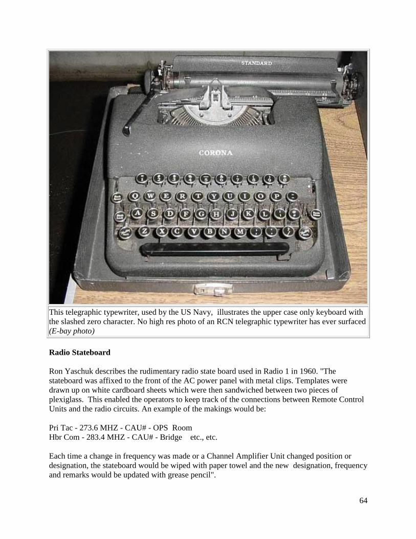
64
This telegraphic typewriter, used by the US Navy, illustrates the upper case only keyboard with
the slashed zero character. No high res photo of an RCN telegraphic typewriter has ever surfaced
(E-bay photo)
Radio Stateboard
Ron Yaschuk describes the rudimentary radio state board used in Radio 1 in 1960. "The
stateboard was affixed to the front of the AC power panel with metal clips. Templates were
drawn up on white cardboard sheets which were then sandwiched between two pieces of
plexiglass. This enabled the operators to keep track of the connections between Remote Control
Units and the radio circuits. An example of the makings would be:
Pri Tac - 273.6 MHZ - CAU# - OPS Room
Hbr Com - 283.4 MHZ - CAU# - Bridge etc., etc.
Each time a change in frequency was made or a Channel Amplifier Unit changed position or
designation, the stateboard would be wiped with paper towel and the new designation, frequency
and remarks would be updated with grease pencil".
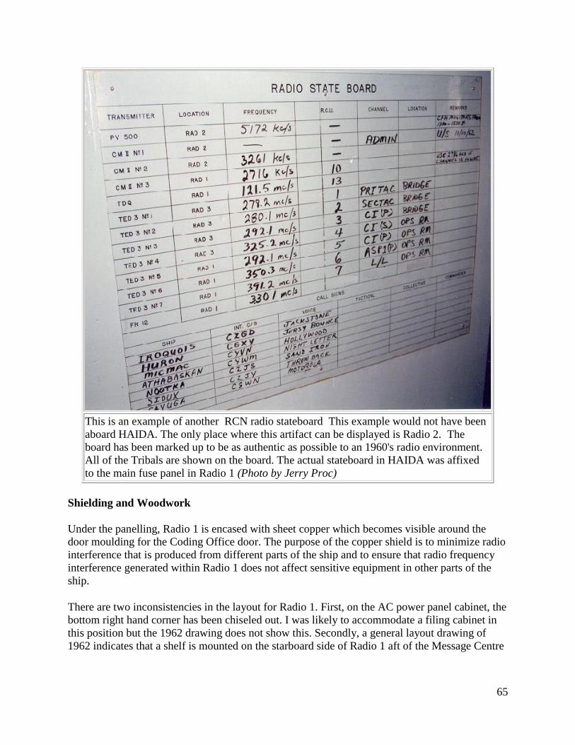
65
This is an example of another RCN radio stateboard This example would not have been
aboard HAIDA. The only place where this artifact can be displayed is Radio 2. The
board has been marked up to be as authentic as possible to an 1960's radio environment.
All of the Tribals are shown on the board. The actual stateboard in HAIDA was affixed
to the main fuse panel in Radio 1 (Photo by Jerry Proc)
Shielding and Woodwork
Under the panelling, Radio 1 is encased with sheet copper which becomes visible around the
door moulding for the Coding Office door. The purpose of the copper shield is to minimize radio
interference that is produced from different parts of the ship and to ensure that radio frequency
interference generated within Radio 1 does not affect sensitive equipment in other parts of the
ship.
There are two inconsistencies in the layout for Radio 1. First, on the AC power panel cabinet, the
bottom right hand corner has been chiseled out. I was likely to accommodate a filing cabinet in
this position but the 1962 drawing does not show this. Secondly, a general layout drawing of
1962 indicates that a shelf is mounted on the starboard side of Radio 1 aft of the Message Centre
66
bulkhead. This has been restored just like the drawing shows, but in reality, there was something
much larger installed as evidenced by the silhouette of newer varnish.
Sound Powered Telephones
There are two types of telephones installed on HAIDA. One type is the single line set
and the other type is a selectable, six line unit. To originate a call on a single line set,
the user turns the crank on the phone. This sends a ring voltage down the line which
powers a buzzer and illuminates a neon lamp on the remote unit. The remote user than
picks up the handset and communication can be established with the use of push-to-
talk switches. Phones can be wired as party lines, so rotating the crank on one phone
makes all of the other phones ring. By using ringing codes, only a certain phone will
get answered. On a party line, the recipient of a call listens for the correct ringing code
then selects the proper line with a rotary switch. The telephone system uses three wire,
armoured cable for communication. White is common, black is voice, and red is ring.
HAIDA's original telephones were manufactured by the Telephone Mfg. Company in
London England. In later years, the RCN retrofitted most of the telephones with a
handset stowage compartment. The photo illustrates a sound powered telephone in a
badly deteriorated state. After 6 to 8 hours labour, the phones can be restored back to
their 1960's condition
Voice Pipe
Besides being used for the transmission of voice traffic, the voice pipe in Radio 1 was also used
to move paper messages between the bridge and radio room. Messages were placed in a small
canister known as the 'bucket'. This was raised and lowered from the bridge using a string known
as Coston Gunline. When there was a message destined for the bridge, the Radioman signalled
the bridge by pressing a switch next to the voice pipe. The party on the bridge would then haul
up the message. On occasion, the string would break and the bucket became a 'bullet' which
would then provide the 'sender' with a great surprise. Strange items were known to travel through
those voice pipes.
67
1.17 MESSAGE CENTRE
LOCATION : Part of Radio Room 1
YEAR OF INSTALLATION : 1952 with additions in 1957 and 1962. Radio equipment
restoration completed April 17, 1993.
CREW COMPLEMENT : 1
PURPOSE OF THIS ROOM : In 1957, this was the main focal point for the processing,
distribution and filing of all messages that were sent to or from the ship by radio, flashing light,
flags and (in harbour) messenger. By 1962, the area around the desk in Radio 1 was designated
as the Message Filing Area per the note on the drawing. The Message Centre contained much of
ship's radioteletype (RATT) equipment with the remainder being located in Radio 2. When
Radioteletype (RATT) was first introduced to the fleet, broadcast traffic could be cleared at
speeds of 60 wpm as compared to the 25 wpm speed of the CW fleet broadcast. Teletype
equipment was manufactured by the Teletype Corp. of Skokie Illinois.
TELEPHONE CONNECTIONS: Telephone D10 connects with Radio 2 and Radio 3.
HISTORY:
Not built until 1952. Space reclaimed from Radio 1 as noted in the diagram.
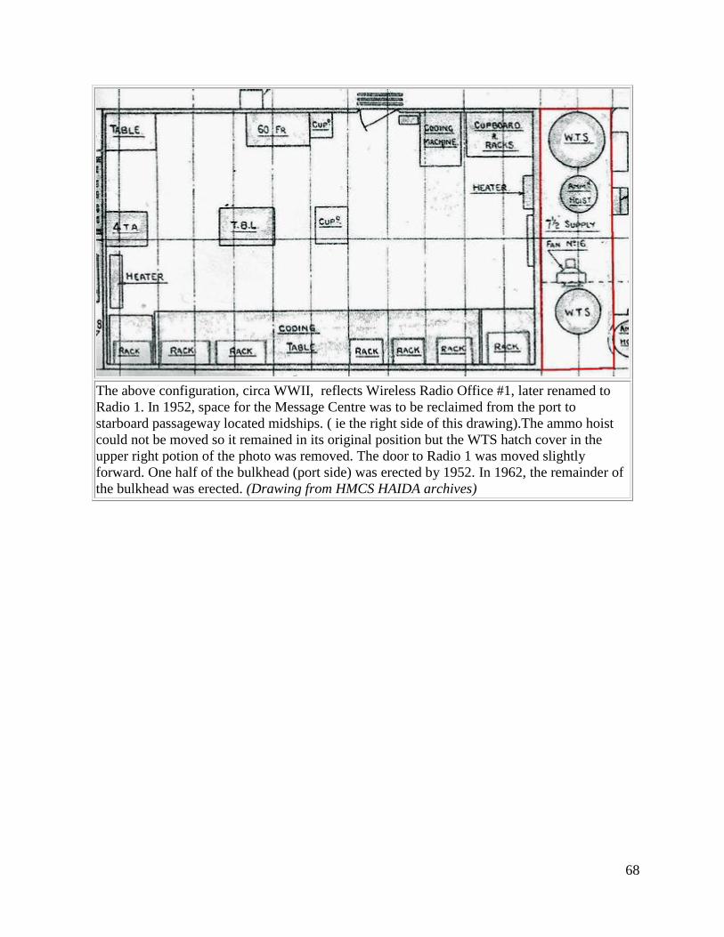
68
The above configuration, circa WWII, reflects Wireless Radio Office #1, later renamed to
Radio 1. In 1952, space for the Message Centre was to be reclaimed from the port to
starboard passageway located midships. ( ie the right side of this drawing).The ammo hoist
could not be moved so it remained in its original position but the WTS hatch cover in the
upper right potion of the photo was removed. The door to Radio 1 was moved slightly
forward. One half of the bulkhead (port side) was erected by 1952. In 1962, the remainder of
the bulkhead was erected. (Drawing from HMCS HAIDA archives)
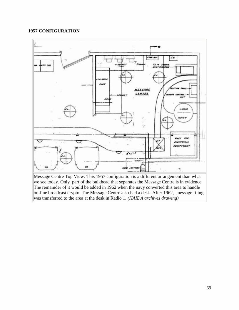
69
1957 CONFIGURATION
Message Centre Top View: This 1957 configuration is a different arrangement than what
we see today. Only part of the bulkhead that separates the Message Centre is in evidence.
The remainder of it would be added in 1962 when the navy converted this area to handle
on-line broadcast crypto. The Message Centre also had a desk After 1962, message filing
was transferred to the area at the desk in Radio 1. (HAIDA archives drawing)
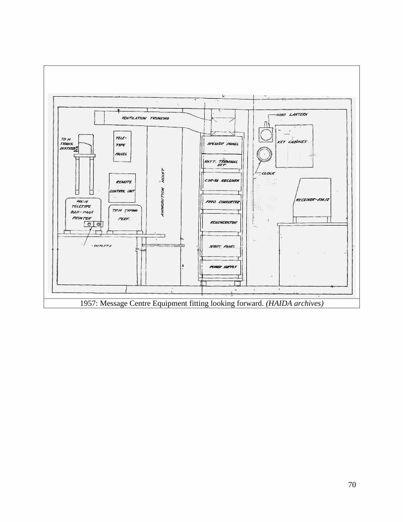
70
1957: Message Centre Equipment fitting looking forward. (HAIDA archives)
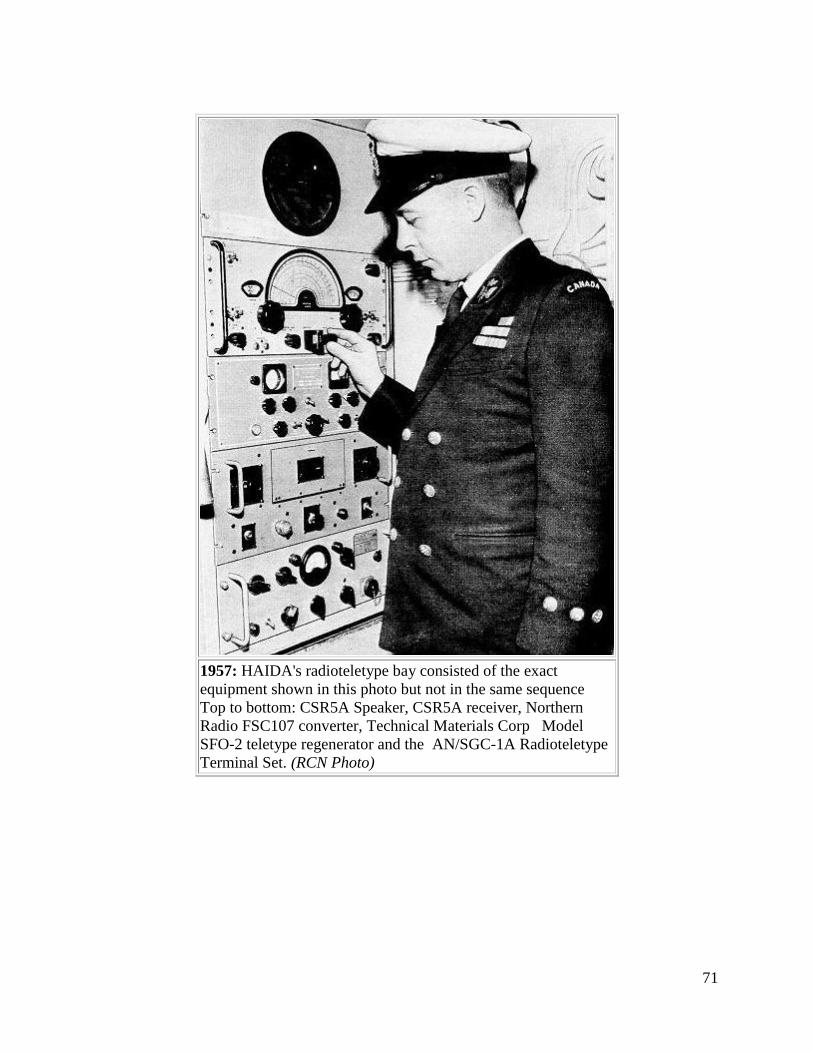
71
1957: HAIDA's radioteletype bay consisted of the exact
equipment shown in this photo but not in the same sequence
Top to bottom: CSR5A Speaker, CSR5A receiver, Northern
Radio FSC107 converter, Technical Materials Corp Model
SFO-2 teletype regenerator and the AN/SGC-1A Radioteletype
Terminal Set. (RCN Photo)
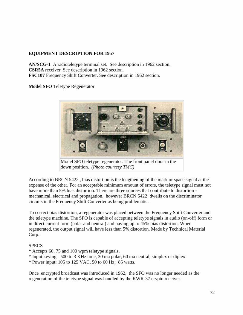
72
EQUIPMENT DESCRIPTION FOR 1957
AN/SCG-1 A radioteletype terminal set. See description in 1962 section.
CSR5A receiver. See description in 1962 section.
FSC107 Frequency Shift Converter. See description in 1962 section.
Model SFO Teletype Regenerator.
Model SFO teletype regenerator. The front panel door in the
down position. (Photo courtesy TMC)
According to BRCN 5422 , bias distortion is the lengthening of the mark or space signal at the
expense of the other. For an acceptable minimum amount of errors, the teletype signal must not
have more than 5% bias distortion. There are three sources that contribute to distortion -
mechanical, electrical and propagation., however BRCN 5422 dwells on the discriminator
circuits in the Frequency Shift Converter as being problematic.
To correct bias distortion, a regenerator was placed between the Frequency Shift Converter and
the teletype machine. The SFO is capable of accepting teletype signals in audio (on-off) form or
in direct current form (polar and neutral) and having up to 45% bias distortion. When
regenerated, the output signal will have less than 5% distortion. Made by Technical Material
Corp.
SPECS
* Accepts 60, 75 and 100 wpm teletype signals.
* Input keying - 500 to 3 KHz tone, 30 ma polar, 60 ma neutral, simplex or diplex
* Power input: 105 to 125 VAC, 50 to 60 Hz; 85 watts.
Once encrypted broadcast was introduced in 1962, the SFO was no longer needed as the
regeneration of the teletype signal was handled by the KWR-37 crypto receiver.
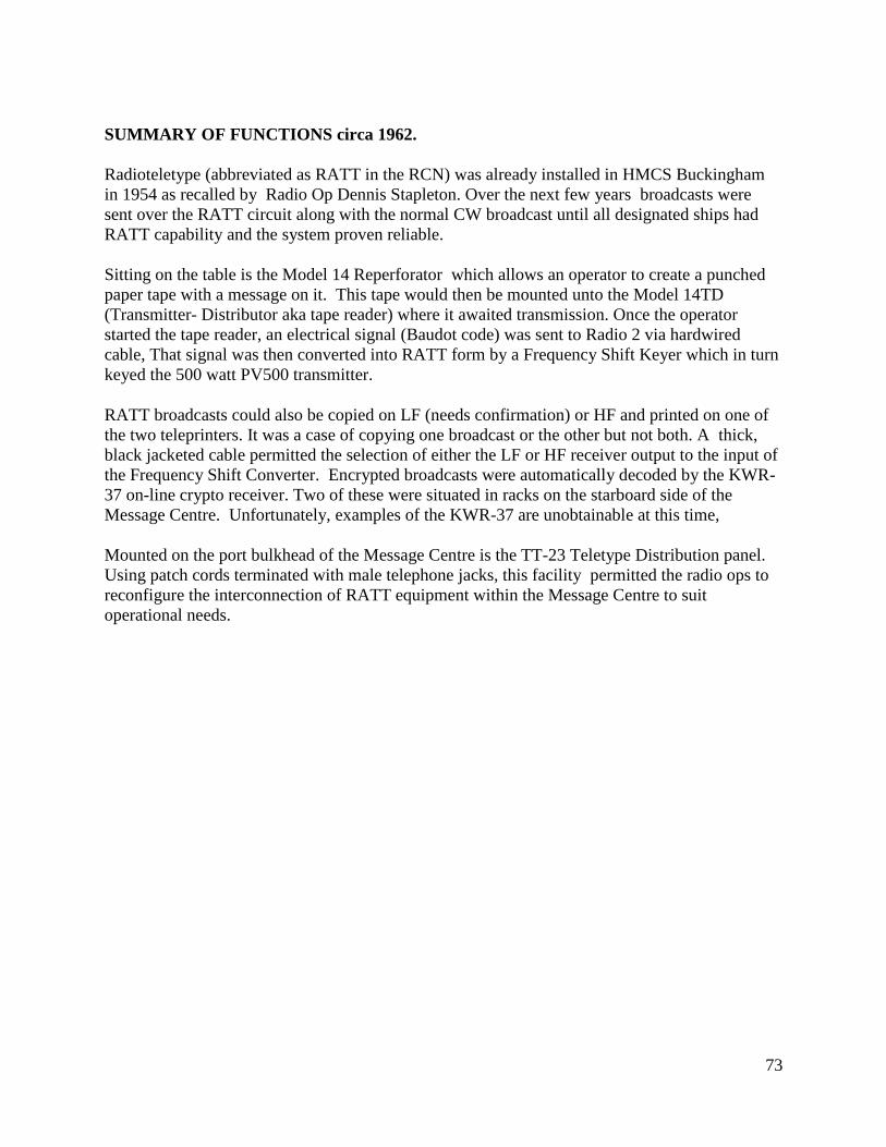
73
SUMMARY OF FUNCTIONS circa 1962.
Radioteletype (abbreviated as RATT in the RCN) was already installed in HMCS Buckingham
in 1954 as recalled by Radio Op Dennis Stapleton. Over the next few years broadcasts were
sent over the RATT circuit along with the normal CW broadcast until all designated ships had
RATT capability and the system proven reliable.
Sitting on the table is the Model 14 Reperforator which allows an operator to create a punched
paper tape with a message on it. This tape would then be mounted unto the Model 14TD
(Transmitter- Distributor aka tape reader) where it awaited transmission. Once the operator
started the tape reader, an electrical signal (Baudot code) was sent to Radio 2 via hardwired
cable, That signal was then converted into RATT form by a Frequency Shift Keyer which in turn
keyed the 500 watt PV500 transmitter.
RATT broadcasts could also be copied on LF (needs confirmation) or HF and printed on one of
the two teleprinters. It was a case of copying one broadcast or the other but not both. A thick,
black jacketed cable permitted the selection of either the LF or HF receiver output to the input of
the Frequency Shift Converter. Encrypted broadcasts were automatically decoded by the KWR-
37 on-line crypto receiver. Two of these were situated in racks on the starboard side of the
Message Centre. Unfortunately, examples of the KWR-37 are unobtainable at this time,
Mounted on the port bulkhead of the Message Centre is the TT-23 Teletype Distribution panel.
Using patch cords terminated with male telephone jacks, this facility permitted the radio ops to
reconfigure the interconnection of RATT equipment within the Message Centre to suit
operational needs.
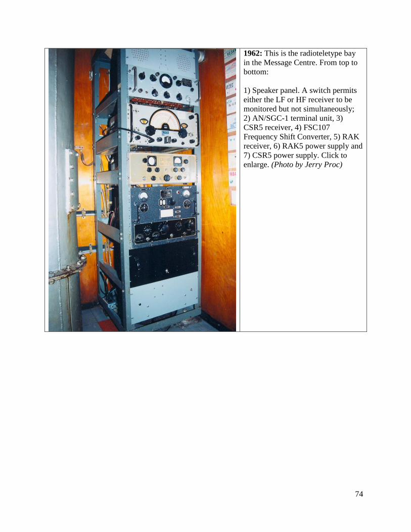
74
1962: This is the radioteletype bay
in the Message Centre. From top to
bottom:
1) Speaker panel. A switch permits
either the LF or HF receiver to be
monitored but not simultaneously;
2) AN/SGC-1 terminal unit, 3)
CSR5 receiver, 4) FSC107
Frequency Shift Converter, 5) RAK
receiver, 6) RAK5 power supply and
7) CSR5 power supply. Click to
enlarge. (Photo by Jerry Proc)
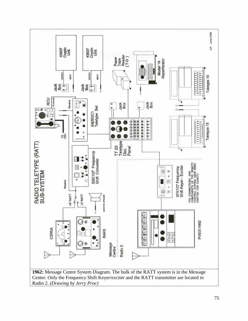
75
1962: Message Centre System Diagram. The bulk of the RATT system is in the Message
Center. Only the Frequency Shift Keyer/exciter and the RATT transmitter are located in
Radio 2. (Drawing by Jerry Proc)
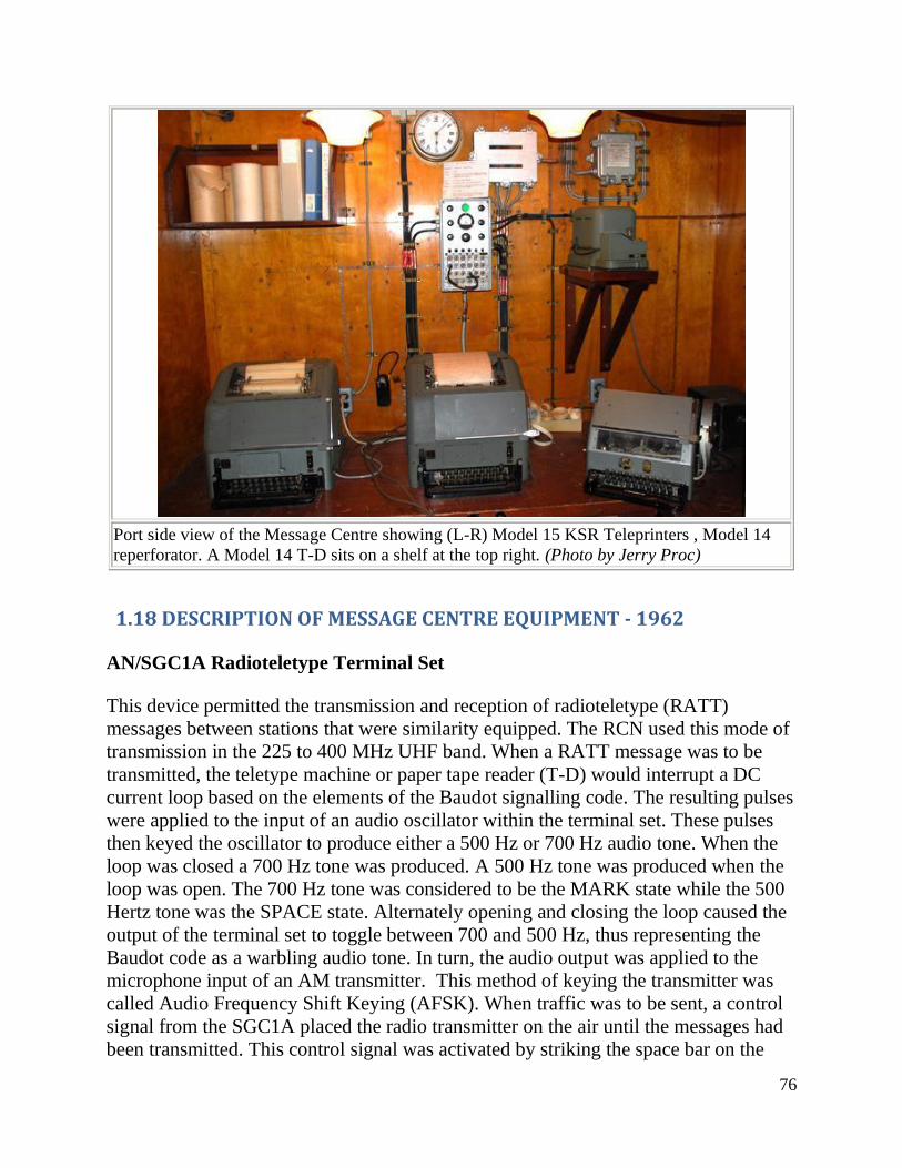
76
Port side view of the Message Centre showing (L-R) Model 15 KSR Teleprinters , Model 14
reperforator. A Model 14 T-D sits on a shelf at the top right. (Photo by Jerry Proc)
1.18 DESCRIPTION OF MESSAGE CENTRE EQUIPMENT - 1962
AN/SGC1A Radioteletype Terminal Set
This device permitted the transmission and reception of radioteletype (RATT)
messages between stations that were similarity equipped. The RCN used this mode of
transmission in the 225 to 400 MHz UHF band. When a RATT message was to be
transmitted, the teletype machine or paper tape reader (T-D) would interrupt a DC
current loop based on the elements of the Baudot signalling code. The resulting pulses
were applied to the input of an audio oscillator within the terminal set. These pulses
then keyed the oscillator to produce either a 500 Hz or 700 Hz audio tone. When the
loop was closed a 700 Hz tone was produced. A 500 Hz tone was produced when the
loop was open. The 700 Hz tone was considered to be the MARK state while the 500
Hertz tone was the SPACE state. Alternately opening and closing the loop caused the
output of the terminal set to toggle between 700 and 500 Hz, thus representing the
Baudot code as a warbling audio tone. In turn, the audio output was applied to the
microphone input of an AM transmitter. This method of keying the transmitter was
called Audio Frequency Shift Keying (AFSK). When traffic was to be sent, a control
signal from the SGC1A placed the radio transmitter on the air until the messages had
been transmitted. This control signal was activated by striking the space bar on the
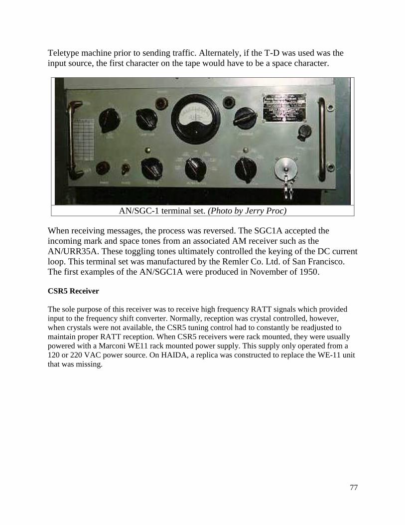
77
Teletype machine prior to sending traffic. Alternately, if the T-D was used was the
input source, the first character on the tape would have to be a space character.
AN/SGC-1 terminal set. (Photo by Jerry Proc)
When receiving messages, the process was reversed. The SGC1A accepted the
incoming mark and space tones from an associated AM receiver such as the
AN/URR35A. These toggling tones ultimately controlled the keying of the DC current
loop. This terminal set was manufactured by the Remler Co. Ltd. of San Francisco.
The first examples of the AN/SGC1A were produced in November of 1950.
CSR5 Receiver
The sole purpose of this receiver was to receive high frequency RATT signals which provided
input to the frequency shift converter. Normally, reception was crystal controlled, however,
when crystals were not available, the CSR5 tuning control had to constantly be readjusted to
maintain proper RATT reception. When CSR5 receivers were rack mounted, they were usually
powered with a Marconi WE11 rack mounted power supply. This supply only operated from a
120 or 220 VAC power source. On HAIDA, a replica was constructed to replace the WE-11 unit
that was missing.
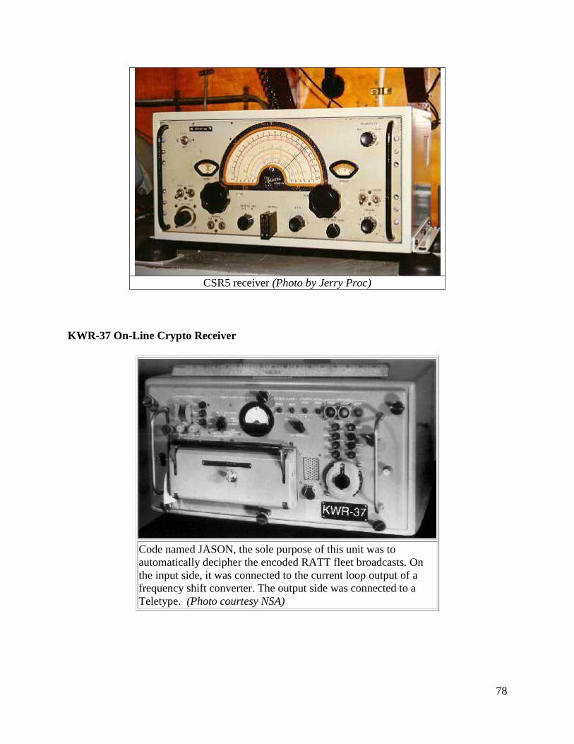
78
CSR5 receiver (Photo by Jerry Proc)
KWR-37 On-Line Crypto Receiver
Code named JASON, the sole purpose of this unit was to
automatically decipher the encoded RATT fleet broadcasts. On
the input side, it was connected to the current loop output of a
frequency shift converter. The output side was connected to a
Teletype. (Photo courtesy NSA)
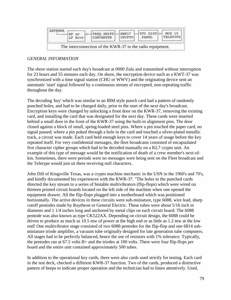
79
The interconnection of the KWR-37 to the radio equipment.
GENERAL INFORMATION
The shore station started each day's broadcast at 0000 Zulu and transmitted without interruption
for 23 hours and 55 minutes each day. On shore, the encryption device such as a KWT-37 was
synchronized with a time signal station (CHU or WWV) and the originating device sent an
automatic 'start' signal followed by a continuous stream of encrypted, non-repeating traffic
throughout the day.
The decoding 'key' which was similar to an IBM style punch card had a pattern of randomly
punched holes, and had to be changed daily, prior to the start of the next day's broadcast.
Encryption keys were changed by unlocking a front door on the KWR-37, removing the existing
card, and installing the card that was designated for the next day. These cards were inserted
behind a small door in the front of the KWR-37 using the built-in alignment pins. The door
closed against a block of small, spring-loaded steel pins. Where a pin touched the paper card, no
signal passed; where a pin poked through a hole in the card and touched a silver-plated metallic
track, a circuit was made. Each card held enough keys to cover 14 years of usage before the key
repeated itself. For very confidential messages, the fleet broadcasts consisted of encapsulated
five character cipher groups which had to be decoded manually on a KL7 crypto unit. An
example of this type of message would be the notification of death of a crew member's next-of-
kin. Sometimes, there were periods were no messages were being sent on the Fleet broadcast and
the Teletype would just sit there receiving null characters.
John Dill of Kingsville Texas, was a crypto machine mechanic in the USN in the 1960's and 70's,
and kindly documented his experiences with the KWR-37. "The holes in the punched cards
directed the key stream to a series of bistable multivibrators (flip-flops) which were wired on
thirteen printed circuit boards located on the left side of the machine when one opened the
equipment drawer. All the flip-flops plugged into a motherboard which was positioned
horizontally. The active devices in these circuits were sub-miniature, type 6088, wire lead, sharp
cutoff pentodes made by Raytheon or General Electric. These tubes were about 5/16 inch in
diameter and 1 1/4 inches long and anchored by metal clips on each circuit board. The 6088
pentode was also known as type CK522AX. Depending on circuit design, the 6088 could be
driven to produce as much as 10.5 mw of power at the high end or as little as 1.2 mw at the low
end! One multivibrator stage consisted of two 6088 pentodes for the flip-flop and one 6814 sub-
miniature triode amplifier, a vacuum tube originally designed for late generation tube computers.
All stages had to be perfectly balanced, hence the use of resistors with 1% tolerance. Typically,
the pentodes ran at 67.5 volts B+ and the triodes at 100 volts. There were four flip-flops per
board and the entire unit contained approximately 500 tubes.
In addition to the operational key cards, there were also cards used strictly for testing. Each card
in the test deck, checked a different KWR-37 function. Two of the cards, produced a distinctive
pattern of beeps to indicate proper operation and the technician had to listen attentively. Used,
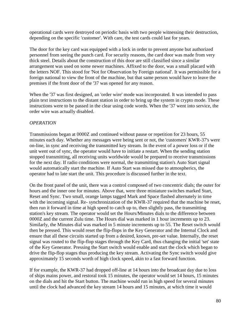
80
operational cards were destroyed on periodic basis with two people witnessing their destruction,
depending on the specific 'customer'. With care, the test cards could last for years.
The door for the key card was equipped with a lock in order to prevent anyone but authorized
personnel from seeing the punch card. For security reasons, the card door was made from very
thick steel. Details about the construction of this door are still classified since a similar
arrangement was used on some newer machines. Affixed to the door, was a small placard with
the letters NOF. This stood for 'Not for Observation by Foreign national'. It was permissible for a
foreign national to view the front of the machine, but that same person would have to leave the
premises if the front door of the '37 was opened for any reason.
When the '37 was first designed, an 'order wire' mode was incorporated. It was intended to pass
plain text instructions to the distant station in order to bring up the system in crypto mode. These
instructions were to be passed in the clear using code words. When the '37 went into service, the
order wire was actually disabled.
OPERATION
Transmissions began at 0000Z and continued without pause or repetition for 23 hours, 55
minutes each day. Whether any messages were being sent or not, the 'customers' KWR-37's were
on-line, in sync and receiving the transmitted key stream. In the event of a power loss or if the
unit went out of sync, the operator would have to initiate a restart. When the sending station
stopped transmitting, all receiving units worldwide would be prepared to receive transmissions
for the next day. If radio conditions were normal, the transmitting station's Auto Start signal
would automatically start the machine. If Auto Start was missed due to atmospherics, the
operator had to late start the unit. This procedure is discussed further in the text.
On the front panel of the unit, there was a control composed of two concentric dials; the outer for
hours and the inner one for minutes. Above that, were three miniature switches marked Start,
Reset and Sync. Two small, orange lamps tagged Mark and Space flashed alternately in time
with the incoming signal. Re- synchronization of the KWR-37 required that the machine be reset,
then run it forward in time at high speed to catch up to, then slightly pass, the transmitting
station's key stream. The operator would set the Hours/Minutes dials to the difference between
0000Z and the current Zulu time. The Hours dial was marked in 1 hour increments up to 23.
Similarly, the Minutes dial was marked in 5 minute increments up to 55. The Reset switch would
then be pressed. This would reset the flip-flops in the Key Generator and the Internal Clock and
ensure that all these circuits started up from a desired, known, pre-set value. Internally, the reset
signal was routed to the flip-flop stages through the Key Card, thus changing the initial 'set' state
of the Key Generator. Pressing the Start switch would enable and start the clock which began to
drive the flip-flop stages thus producing the key stream. Activating the Sync switch would give
approximately 15 seconds worth of high clock speed, akin to a fast forward function.
If for example, the KWR-37 had dropped off-line at 14 hours into the broadcast day due to loss
of ships mains power, and restoral took 15 minutes, the operator would set 14 hours, 15 minutes
on the dials and hit the Start button. The machine would run in high speed for several minutes
until the clock had advanced the key stream 14 hours and 15 minutes, at which time it would
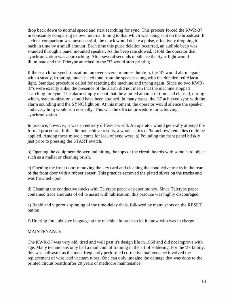
81
drop back down to normal speed and start searching for sync. This process forced the KWR-37
in constantly comparing its own internal timing to that which was being sent on the broadcast. If
a clock comparison was unsuccessful, the clock would delete a pulse, effectively dropping it
back in time by a small amount. Each time this pulse deletion occurred, an audible beep was
sounded through a panel mounted speaker. As the beep rate slowed, it told the operator that
synchronization was approaching. After several seconds of silence the Sync light would
illuminate and the Teletype attached to the '37 would start printing.
If the search for synchronization ran over several minutes duration, the '37 would alarm again
with a steady, irritating, much-hated tone from the speaker along with the dreaded red Alarm
light. Standard procedure called for resetting the machine and trying again. Since no two KWR-
37's were exactly alike, the presence of the alarm did not mean that the machine stopped
searching for sync. The alarm simply meant that the allotted amount of time had elapsed, during
which, synchronization should have been attained. In many cases, the '37 achieved sync with the
alarm sounding and the SYNC light on. At this moment, the operator would silence the speaker
and everything would run normally. This was the official procedure for achieving
synchronization.
In practice, however, it was an entirely different world. An operator would generally attempt the
formal procedure. If this did not achieve results, a whole series of 'homebrew' remedies could be
applied. Among these miracle cures for lack of sync were: a) Pounding the front panel briskly
just prior to pressing the START switch.
b) Opening the equipment drawer and hitting the tops of the circuit boards with some hard object
such as a mallet or cleaning brush.
c) Opening the front door; removing the key card and cleaning the conductive tracks in the rear
of the front door with a rubber eraser. This practice removed the plated silver on the tracks and
was frowned upon.
d) Cleaning the conductive tracks with Teletype paper or paper money. Since Teletype paper
contained trace amounts of oil to assist with lubrication, this practice was highly discouraged.
e) Rapid and vigorous spinning of the time-delay dials, followed by many shots on the RESET
button.
f) Uttering foul, abusive language at the machine in order to let it know who was in charge.
MAINTENANCE
The KWR-37 was very old, tired and well past it's design life in 1968 and did not improve with
age. Many technicians only had a modicum of training in the art of soldering. For the '37 family,
this was a disaster as the most frequently performed corrective maintenance involved the
replacement of wire lead vacuum tubes. One can only imagine the damage that was done to the
printed circuit boards after 20 years of mediocre maintenance.
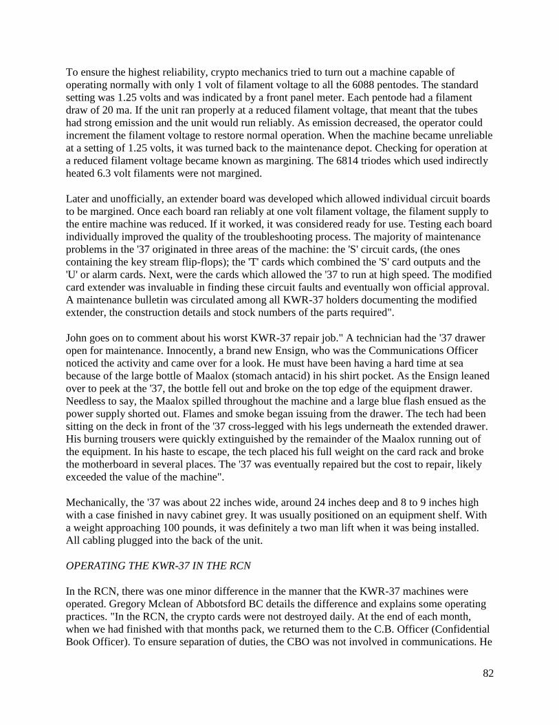
82
To ensure the highest reliability, crypto mechanics tried to turn out a machine capable of
operating normally with only 1 volt of filament voltage to all the 6088 pentodes. The standard
setting was 1.25 volts and was indicated by a front panel meter. Each pentode had a filament
draw of 20 ma. If the unit ran properly at a reduced filament voltage, that meant that the tubes
had strong emission and the unit would run reliably. As emission decreased, the operator could
increment the filament voltage to restore normal operation. When the machine became unreliable
at a setting of 1.25 volts, it was turned back to the maintenance depot. Checking for operation at
a reduced filament voltage became known as margining. The 6814 triodes which used indirectly
heated 6.3 volt filaments were not margined.
Later and unofficially, an extender board was developed which allowed individual circuit boards
to be margined. Once each board ran reliably at one volt filament voltage, the filament supply to
the entire machine was reduced. If it worked, it was considered ready for use. Testing each board
individually improved the quality of the troubleshooting process. The majority of maintenance
problems in the '37 originated in three areas of the machine: the 'S' circuit cards, (the ones
containing the key stream flip-flops); the 'T' cards which combined the 'S' card outputs and the
'U' or alarm cards. Next, were the cards which allowed the '37 to run at high speed. The modified
card extender was invaluable in finding these circuit faults and eventually won official approval.
A maintenance bulletin was circulated among all KWR-37 holders documenting the modified
extender, the construction details and stock numbers of the parts required".
John goes on to comment about his worst KWR-37 repair job." A technician had the '37 drawer
open for maintenance. Innocently, a brand new Ensign, who was the Communications Officer
noticed the activity and came over for a look. He must have been having a hard time at sea
because of the large bottle of Maalox (stomach antacid) in his shirt pocket. As the Ensign leaned
over to peek at the '37, the bottle fell out and broke on the top edge of the equipment drawer.
Needless to say, the Maalox spilled throughout the machine and a large blue flash ensued as the
power supply shorted out. Flames and smoke began issuing from the drawer. The tech had been
sitting on the deck in front of the '37 cross-legged with his legs underneath the extended drawer.
His burning trousers were quickly extinguished by the remainder of the Maalox running out of
the equipment. In his haste to escape, the tech placed his full weight on the card rack and broke
the motherboard in several places. The '37 was eventually repaired but the cost to repair, likely
exceeded the value of the machine".
Mechanically, the '37 was about 22 inches wide, around 24 inches deep and 8 to 9 inches high
with a case finished in navy cabinet grey. It was usually positioned on an equipment shelf. With
a weight approaching 100 pounds, it was definitely a two man lift when it was being installed.
All cabling plugged into the back of the unit.
OPERATING THE KWR-37 IN THE RCN
In the RCN, there was one minor difference in the manner that the KWR-37 machines were
operated. Gregory Mclean of Abbotsford BC details the difference and explains some operating
practices. "In the RCN, the crypto cards were not destroyed daily. At the end of each month,
when we had finished with that months pack, we returned them to the C.B. Officer (Confidential
Book Officer). To ensure separation of duties, the CBO was not involved in communications. He
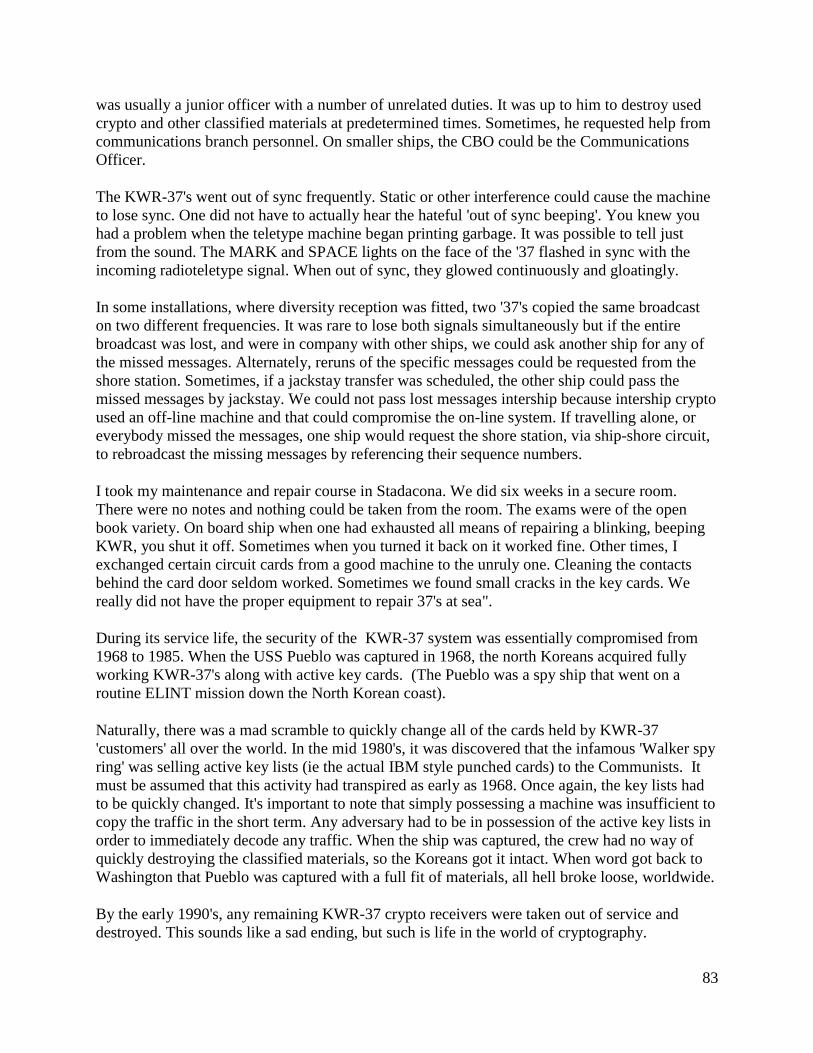
83
was usually a junior officer with a number of unrelated duties. It was up to him to destroy used
crypto and other classified materials at predetermined times. Sometimes, he requested help from
communications branch personnel. On smaller ships, the CBO could be the Communications
Officer.
The KWR-37's went out of sync frequently. Static or other interference could cause the machine
to lose sync. One did not have to actually hear the hateful 'out of sync beeping'. You knew you
had a problem when the teletype machine began printing garbage. It was possible to tell just
from the sound. The MARK and SPACE lights on the face of the '37 flashed in sync with the
incoming radioteletype signal. When out of sync, they glowed continuously and gloatingly.
In some installations, where diversity reception was fitted, two '37's copied the same broadcast
on two different frequencies. It was rare to lose both signals simultaneously but if the entire
broadcast was lost, and were in company with other ships, we could ask another ship for any of
the missed messages. Alternately, reruns of the specific messages could be requested from the
shore station. Sometimes, if a jackstay transfer was scheduled, the other ship could pass the
missed messages by jackstay. We could not pass lost messages intership because intership crypto
used an off-line machine and that could compromise the on-line system. If travelling alone, or
everybody missed the messages, one ship would request the shore station, via ship-shore circuit,
to rebroadcast the missing messages by referencing their sequence numbers.
I took my maintenance and repair course in Stadacona. We did six weeks in a secure room.
There were no notes and nothing could be taken from the room. The exams were of the open
book variety. On board ship when one had exhausted all means of repairing a blinking, beeping
KWR, you shut it off. Sometimes when you turned it back on it worked fine. Other times, I
exchanged certain circuit cards from a good machine to the unruly one. Cleaning the contacts
behind the card door seldom worked. Sometimes we found small cracks in the key cards. We
really did not have the proper equipment to repair 37's at sea".
During its service life, the security of the KWR-37 system was essentially compromised from
1968 to 1985. When the USS Pueblo was captured in 1968, the north Koreans acquired fully
working KWR-37's along with active key cards. (The Pueblo was a spy ship that went on a
routine ELINT mission down the North Korean coast).
Naturally, there was a mad scramble to quickly change all of the cards held by KWR-37
'customers' all over the world. In the mid 1980's, it was discovered that the infamous 'Walker spy
ring' was selling active key lists (ie the actual IBM style punched cards) to the Communists. It
must be assumed that this activity had transpired as early as 1968. Once again, the key lists had
to be quickly changed. It's important to note that simply possessing a machine was insufficient to
copy the traffic in the short term. Any adversary had to be in possession of the active key lists in
order to immediately decode any traffic. When the ship was captured, the crew had no way of
quickly destroying the classified materials, so the Koreans got it intact. When word got back to
Washington that Pueblo was captured with a full fit of materials, all hell broke loose, worldwide.
By the early 1990's, any remaining KWR-37 crypto receivers were taken out of service and
destroyed. This sounds like a sad ending, but such is life in the world of cryptography.
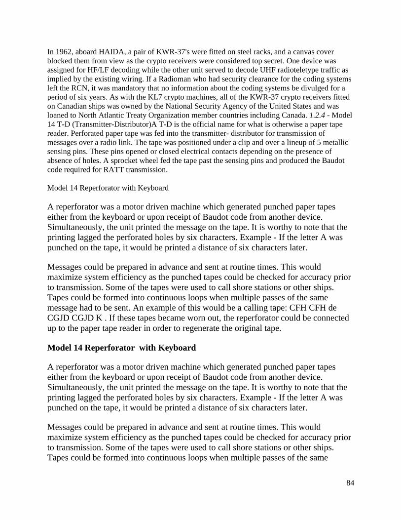
84
In 1962, aboard HAIDA, a pair of KWR-37's were fitted on steel racks, and a canvas cover
blocked them from view as the crypto receivers were considered top secret. One device was
assigned for HF/LF decoding while the other unit served to decode UHF radioteletype traffic as
implied by the existing wiring. If a Radioman who had security clearance for the coding systems
left the RCN, it was mandatory that no information about the coding systems be divulged for a
period of six years. As with the KL7 crypto machines, all of the KWR-37 crypto receivers fitted
on Canadian ships was owned by the National Security Agency of the United States and was
loaned to North Atlantic Treaty Organization member countries including Canada. 1.2.4 - Model
14 T-D (Transmitter-Distributor)A T-D is the official name for what is otherwise a paper tape
reader. Perforated paper tape was fed into the transmitter- distributor for transmission of
messages over a radio link. The tape was positioned under a clip and over a lineup of 5 metallic
sensing pins. These pins opened or closed electrical contacts depending on the presence of
absence of holes. A sprocket wheel fed the tape past the sensing pins and produced the Baudot
code required for RATT transmission.
Model 14 Reperforator with Keyboard
A reperforator was a motor driven machine which generated punched paper tapes
either from the keyboard or upon receipt of Baudot code from another device.
Simultaneously, the unit printed the message on the tape. It is worthy to note that the
printing lagged the perforated holes by six characters. Example - If the letter A was
punched on the tape, it would be printed a distance of six characters later.
Messages could be prepared in advance and sent at routine times. This would
maximize system efficiency as the punched tapes could be checked for accuracy prior
to transmission. Some of the tapes were used to call shore stations or other ships.
Tapes could be formed into continuous loops when multiple passes of the same
message had to be sent. An example of this would be a calling tape: CFH CFH de
CGJD CGJD K . If these tapes became worn out, the reperforator could be connected
up to the paper tape reader in order to regenerate the original tape.
Model 14 Reperforator with Keyboard
A reperforator was a motor driven machine which generated punched paper tapes
either from the keyboard or upon receipt of Baudot code from another device.
Simultaneously, the unit printed the message on the tape. It is worthy to note that the
printing lagged the perforated holes by six characters. Example - If the letter A was
punched on the tape, it would be printed a distance of six characters later.
Messages could be prepared in advance and sent at routine times. This would
maximize system efficiency as the punched tapes could be checked for accuracy prior
to transmission. Some of the tapes were used to call shore stations or other ships.
Tapes could be formed into continuous loops when multiple passes of the same
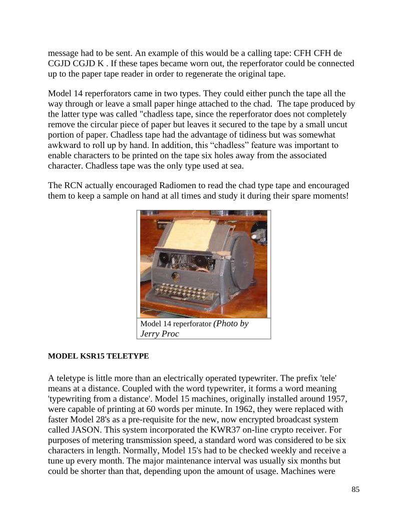
85
message had to be sent. An example of this would be a calling tape: CFH CFH de
CGJD CGJD K . If these tapes became worn out, the reperforator could be connected
up to the paper tape reader in order to regenerate the original tape.
Model 14 reperforators came in two types. They could either punch the tape all the
way through or leave a small paper hinge attached to the chad. The tape produced by
the latter type was called "chadless tape, since the reperforator does not completely
remove the circular piece of paper but leaves it secured to the tape by a small uncut
portion of paper. Chadless tape had the advantage of tidiness but was somewhat
awkward to roll up by hand. In addition, this “chadless” feature was important to
enable characters to be printed on the tape six holes away from the associated
character. Chadless tape was the only type used at sea.
The RCN actually encouraged Radiomen to read the chad type tape and encouraged
them to keep a sample on hand at all times and study it during their spare moments!
Model 14 reperforator (Photo by
Jerry Proc
MODEL KSR15 TELETYPE
A teletype is little more than an electrically operated typewriter. The prefix 'tele'
means at a distance. Coupled with the word typewriter, it forms a word meaning
'typewriting from a distance'. Model 15 machines, originally installed around 1957,
were capable of printing at 60 words per minute. In 1962, they were replaced with
faster Model 28's as a pre-requisite for the new, now encrypted broadcast system
called JASON. This system incorporated the KWR37 on-line crypto receiver. For
purposes of metering transmission speed, a standard word was considered to be six
characters in length. Normally, Model 15's had to be checked weekly and receive a
tune up every month. The major maintenance interval was usually six months but
could be shorter than that, depending upon the amount of usage. Machines were
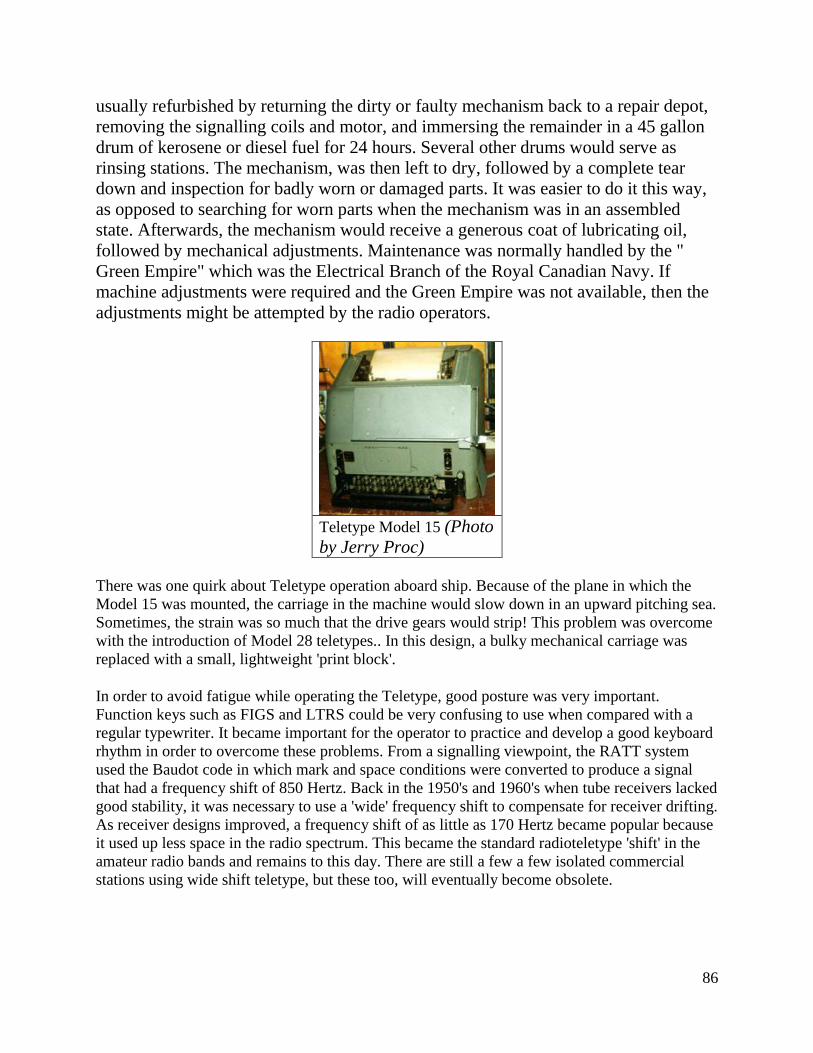
86
usually refurbished by returning the dirty or faulty mechanism back to a repair depot,
removing the signalling coils and motor, and immersing the remainder in a 45 gallon
drum of kerosene or diesel fuel for 24 hours. Several other drums would serve as
rinsing stations. The mechanism, was then left to dry, followed by a complete tear
down and inspection for badly worn or damaged parts. It was easier to do it this way,
as opposed to searching for worn parts when the mechanism was in an assembled
state. Afterwards, the mechanism would receive a generous coat of lubricating oil,
followed by mechanical adjustments. Maintenance was normally handled by the "
Green Empire" which was the Electrical Branch of the Royal Canadian Navy. If
machine adjustments were required and the Green Empire was not available, then the
adjustments might be attempted by the radio operators.
Teletype Model 15 (Photo
by Jerry Proc)
There was one quirk about Teletype operation aboard ship. Because of the plane in which the
Model 15 was mounted, the carriage in the machine would slow down in an upward pitching sea.
Sometimes, the strain was so much that the drive gears would strip! This problem was overcome
with the introduction of Model 28 teletypes.. In this design, a bulky mechanical carriage was
replaced with a small, lightweight 'print block'.
In order to avoid fatigue while operating the Teletype, good posture was very important.
Function keys such as FIGS and LTRS could be very confusing to use when compared with a
regular typewriter. It became important for the operator to practice and develop a good keyboard
rhythm in order to overcome these problems. From a signalling viewpoint, the RATT system
used the Baudot code in which mark and space conditions were converted to produce a signal
that had a frequency shift of 850 Hertz. Back in the 1950's and 1960's when tube receivers lacked
good stability, it was necessary to use a 'wide' frequency shift to compensate for receiver drifting.
As receiver designs improved, a frequency shift of as little as 170 Hertz became popular because
it used up less space in the radio spectrum. This became the standard radioteletype 'shift' in the
amateur radio bands and remains to this day. There are still a few a few isolated commercial
stations using wide shift teletype, but these too, will eventually become obsolete.
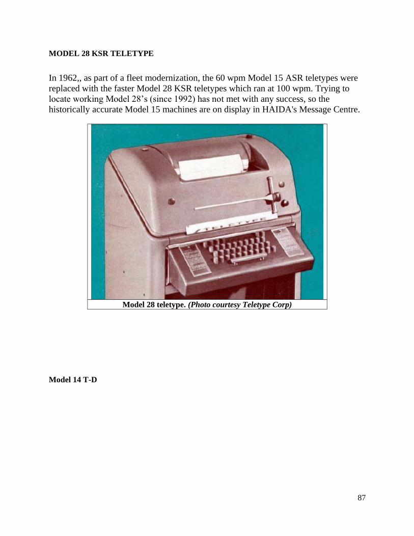
87
MODEL 28 KSR TELETYPE
In 1962,, as part of a fleet modernization, the 60 wpm Model 15 ASR teletypes were
replaced with the faster Model 28 KSR teletypes which ran at 100 wpm. Trying to
locate working Model 28’s (since 1992) has not met with any success, so the
historically accurate Model 15 machines are on display in HAIDA's Message Centre.
Model 28 teletype. (Photo courtesy Teletype Corp)
Model 14 T-D
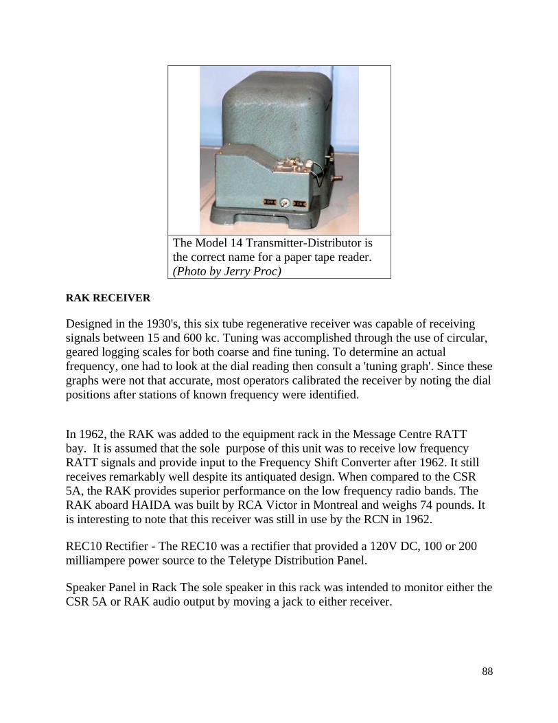
88
The Model 14 Transmitter-Distributor is
the correct name for a paper tape reader.
(Photo by Jerry Proc)
RAK RECEIVER
Designed in the 1930's, this six tube regenerative receiver was capable of receiving
signals between 15 and 600 kc. Tuning was accomplished through the use of circular,
geared logging scales for both coarse and fine tuning. To determine an actual
frequency, one had to look at the dial reading then consult a 'tuning graph'. Since these
graphs were not that accurate, most operators calibrated the receiver by noting the dial
positions after stations of known frequency were identified.
In 1962, the RAK was added to the equipment rack in the Message Centre RATT
bay. It is assumed that the sole purpose of this unit was to receive low frequency
RATT signals and provide input to the Frequency Shift Converter after 1962. It still
receives remarkably well despite its antiquated design. When compared to the CSR
5A, the RAK provides superior performance on the low frequency radio bands. The
RAK aboard HAIDA was built by RCA Victor in Montreal and weighs 74 pounds. It
is interesting to note that this receiver was still in use by the RCN in 1962.
REC10 Rectifier - The REC10 was a rectifier that provided a 120V DC, 100 or 200
milliampere power source to the Teletype Distribution Panel.
Speaker Panel in Rack The sole speaker in this rack was intended to monitor either the
CSR 5A or RAK audio output by moving a jack to either receiver.
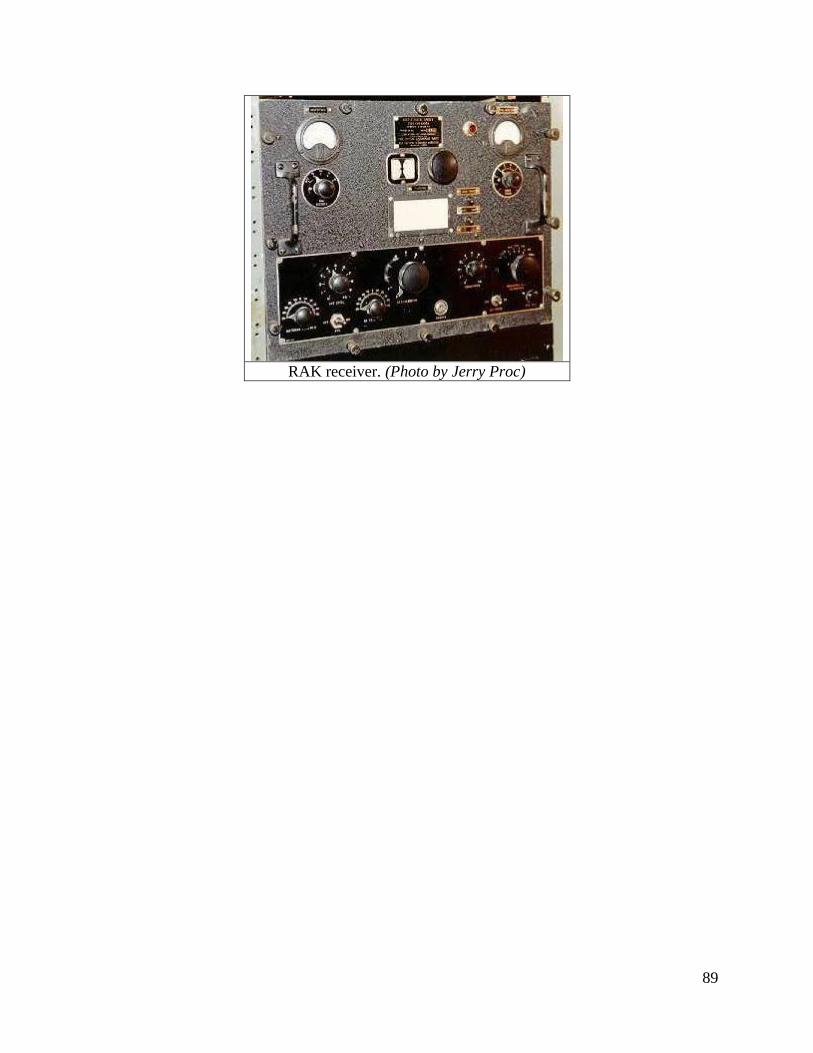
89
RAK receiver. (Photo by Jerry Proc)
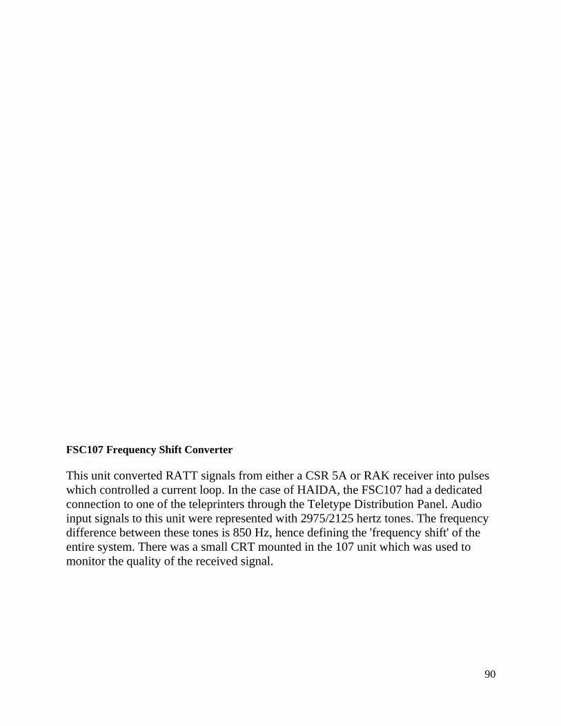
90
FSC107 Frequency Shift Converter
This unit converted RATT signals from either a CSR 5A or RAK receiver into pulses
which controlled a current loop. In the case of HAIDA, the FSC107 had a dedicated
connection to one of the teleprinters through the Teletype Distribution Panel. Audio
input signals to this unit were represented with 2975/2125 hertz tones. The frequency
difference between these tones is 850 Hz, hence defining the 'frequency shift' of the
entire system. There was a small CRT mounted in the 107 unit which was used to
monitor the quality of the received signal.
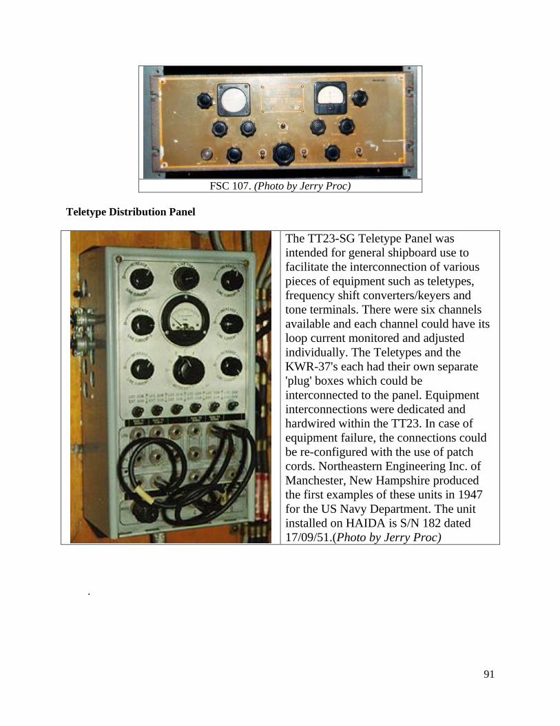
91
FSC 107. (Photo by Jerry Proc)
Teletype Distribution Panel
The TT23-SG Teletype Panel was
intended for general shipboard use to
facilitate the interconnection of various
pieces of equipment such as teletypes,
frequency shift converters/keyers and
tone terminals. There were six channels
available and each channel could have its
loop current monitored and adjusted
individually. The Teletypes and the
KWR-37's each had their own separate
'plug' boxes which could be
interconnected to the panel. Equipment
interconnections were dedicated and
hardwired within the TT23. In case of
equipment failure, the connections could
be re-configured with the use of patch
cords. Northeastern Engineering Inc. of
Manchester, New Hampshire produced
the first examples of these units in 1947
for the US Navy Department. The unit
installed on HAIDA is S/N 182 dated
17/09/51.(Photo by Jerry Proc)
.
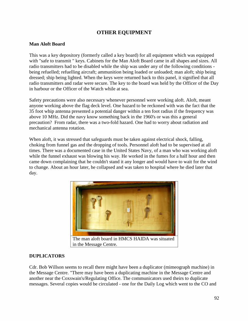
92
OTHER EQUIPMENT
Man Aloft Board
This was a key depository (formerly called a key board) for all equipment which was equipped
with "safe to transmit " keys. Cabinets for the Man Aloft Board came in all shapes and sizes. All
radio transmitters had to be disabled while the ship was under any of the following conditions -
being refuelled; refuelling aircraft; ammunition being loaded or unloaded; man aloft; ship being
dressed; ship being lighted. When the keys were returned back to this panel, it signified that all
radio transmitters and radar were secure. The key to the board was held by the Officer of the Day
in harbour or the Officer of the Watch while at sea.
Safety precautions were also necessary whenever personnel were working aloft. Aloft, meant
anyone working above the flag deck level. One hazard to be reckoned with was the fact that the
35 foot whip antenna presented a potential danger within a ten foot radius if the frequency was
above 10 MHz. Did the navy know something back in the 1960's or was this a general
precaution? From radar, there was a two-fold hazard. One had to worry about radiation and
mechanical antenna rotation.
When aloft, it was stressed that safeguards must be taken against electrical shock, falling,
choking from funnel gas and the dropping of tools. Personnel aloft had to be supervised at all
times. There was a documented case in the United States Navy, of a man who was working aloft
while the funnel exhaust was blowing his way. He worked in the fumes for a half hour and then
came down complaining that he couldn't stand it any longer and would have to wait for the wind
to change. About an hour later, he collapsed and was taken to hospital where he died later that
day.
The man aloft board in HMCS HAIDA was situated
in the Message Centre.
DUPLICATORS
Cdr. Bob Willson seems to recall there might have been a duplicator (mimeograph machine) in
the Message Centre. "There may have been a duplicating machine in the Message Centre and
another near the Coxswain's/Regulating Office. The communicators used theirs to duplicate
messages. Several copies would be circulated - one for the Daily Log which went to the CO and
93
then to the various officers, one for the log in the Message Centre, one for the "Action Officer"
or the Ops Room log, etc. The other was used to print daily orders, which were posted
throughout the ship. Captain and XO's Temporary Memoranda, and multiple copies of letters
would also reproduced by machine in the event that too many carbon papers had to be loaded
into the typewriter".
1.19 MESSAGE CENTRE TRAFFIC VOLUMES
In July 1953, a study was conducted aboard HMCS Huron in an effort to determine traffic
volume The figures are approximate. This volume might have been similar for HAIDA.
Unclassified Traffic
Fleet broadcast incoming messages :44 per day
Ship-shore (HMCS Quebec) outgoing messages: 10 per day
Inter -ship communication
Incoming messages: 20 per day
Outgoing messages: 14 per day
Operational Voice circuits incoming and outgoing messages: 25-30 per day
Classified Traffic
Incoming: 12 per week
Outgoing : 2 since Jan. 17, 1953
1.20 CODING OFFICE DESCRIPTION
LOCATION : Part of Radio Room 1 on the aft end, port side and was only accessible from the
inside of Radio 1.
YEAR OF INSTALLATION : 1950. Doorway relocated around 1953 or 1954.
CREW COMPLEMENT : Usually one.
PURPOSE OF THIS ROOM (circa 1962): To encode messages using a KL7 off-line encoding
machine. There were two units in the Coding Office. Besides being a backup, the standby unit
could be left with the previous day's settings in case any late arriving messages had to be
decoded. The crypto office was always locked unless someone was working in there. The KL-7
system was fitted around 1962.
94
HISTORY
The Coding Office was originally a potato locker. When modified into a Coding Office, it had a
door which opened to the port passageway. Due to improper design, the office had no means of
ventilation unless the door was kept open. That was not permissible under the prevailing security
regulations. A record of temperatures in Radio Office 1 and the Coding Office was kept by
various watches during the period of the exercises off Guantanamo Bay, Cuba, and the Bermuda
Islands which took place in July 1953. With the outside temperature fluctuating from 65 degrees
F. to 70 degrees F., the temperature in the Radio Office and Coding Office was approximately 90
degrees F. This was remedied by installing ventilation and for the security issue, the door was
relocated from the port passageway to the bulkhead between the Coding Office and Radio 1.
Initially Typex cipher machines were installed but later superseded by the TSEC/KL7.
1.21 CODING OFFICE EQUIPMENT DESCRIPTION – 1950’s
Bill Moffatt (LSCV1, RCN 1950-1955) recalls crypto operations in Korea. "During my service
in HMCS Iroquois in Korea in 1952, one of my main duties was decoding messages. We used
these systems.
1. One-time pad. - Messages were received in groups of five numbers. After selecting the
correct starting place in the one-time pad (which was indicated by key groups), we subtracted the
numbers on the pad from the
groups in the message and got the coded message, which we then decoded by using a code book.
2. A British crypto machine called Typex. We inserted certain code wheels into the machine and
set them at certain starting points according to key dates, etc. from a book. Typed in the
encrypted message and the plain language message was printed out on a tape.
3. CCM – A adaptation which permitted the British Typex to interoperate with the American
SIGABA
3. An American crypto machine called Adonis (KL-7).
Our main difficulty with decoding messages was resolving messages that contained garbles. In
doing this, we tried different combinations that could have resulted from incorrect reading of
Morse code, that is, we substituted similar Morse code letters in the portion that came out as
garbled, to see if we could determine what the original message had been and how it might have
been corrupted by incorrect reception of the code. The other method of resolving garbled
portions was the substitution of letters that could have been typo errors. Many of the messages
were from agents in enemy territory and described the position of movements of NKA and ROC
forces which had little to do with ships screening carriers or making island patrols on the west
coast of Korea”.
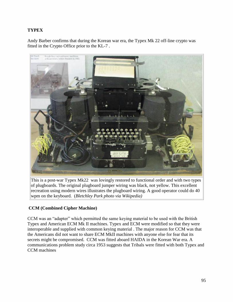
95
TYPEX
Andy Barber confirms that during the Korean war era, the Typex Mk 22 off-line crypto was
fitted in the Crypto Office prior to the KL-7 .
This is a post-war Typex Mk22 was lovingly restored to functional order and with two types
of plugboards. The original plugboard jumper wiring was black, not yellow. This excellent
recreation using modern wires illustrates the plugboard wiring. A good operator could do 40
wpm on the keyboard. (Bletchley Park photo via Wikipedia)
CCM (Combined Cipher Machine)
CCM was an “adapter” which permitted the same keying material to be used with the British
Typex and American ECM Mk II machines. Typex and ECM were modified so that they were
interoperable and supplied with common keying material . The major reason for CCM was that
the Americans did not want to share ECM MkII machines with anyone else for fear that its
secrets might be compromised. CCM was fitted aboard HAIDA in the Korean War era. A
communications problem study circa 1953 suggests that Tribals were fitted with both Typex and
CCM machines
96
CCM Adaptation On Typex
The prerequisite for CCM adaptation is a Typex Mk 23. Specifically, a Mk 22 machine needs to
be modified to a Mk 23 in order to accept the CCM adapter. The Mk 23 can be identified by the
fact that it has an extra socket underneath the main one on the right hand side of the keyboard. It
also has an extra lobe on one of the cams to trip the CCM. There are four long steel posts that are
affixed to the base. The CCM adapter could not be installed in the field. It was a factory-only
modification.
Note that in the above photo, not every Typex was fitted with left and right plugboards. Some
had only one while others didn't have any. If plugboards were fitted, that would have given an
extra degree of complexity to the machine when all that was required was compatibility with
SIGABA. There were 186 different code systems used by Typex so even if the enemy had
broken one, there would still be 185 others to try and break. One Typex maintainer recalls.
"When I was servicing Typex in the RAF, the machines with the left and right plugboards were
the worst to troubleshoot. Invariably the problems were caused by bad connections on the
plugboard"
Ron Mark served as a radio operator aboard HMCS Athabaskan in Korea. He remembers the
following about crypto operations. "In Korea, we operated under the United Nations.
CCM/Typex was a crypto machine used by the British and other Commonwealth Navies.
CCM/SIGABA was a crypto machine used by the American Navy.
Some of the material we received on the broadcast was both Commonwealth and American
crypto since the Task Force could be under American or British command. About 95 percent of
the encrypted traffic on the ship was received on the broadcast. We used both the Type X and
CCM machines to code and decode.
For ship-to-ship encoding/decoding, we used the appropriate machine, and if we were close
enough to the ship it could be sent by CW or Voice on Inter-Ship circuits Otherwise it was sent
to the broadcast centre for onward relay to the ship. During island operations and when working
with Guerrilla groups, we used book code, stencil subtractor or the "Bicycle" machine.
The Bicycle machine was a set of small chains set into a box possibly 12 by 4 inches. It was non
electric and portable. When set up, it would allow you to move the chain to get the desired
output at the readout at the bottom of the box. It was mostly used in landing operations.
The Procedure For Receiving:
1. The message arrived at the crypto office usually typed by the receiving radio operator exactly
as he had received it.
2. The crypto operator set up the date coordinates for the machine, then typed in the code, and
the machine spit out the result and plain text on tape.
97
3. The crypto operator glued up the tape onto a message form and corrected any obvious spelling
mistakes.
4. If it was routine message it was sent to the Message Centre to be typed up by a signalman.
Then it was placed in the message log for viewing by the ships officers.
5. If the message was Operation Immediate or Flash, it was handed directly to the Captain or the
Officer of the Watch on the bridge.
If the atmospheric conditions were bad or, if the radio operator was not on the ball, he could type
some of the CW cypher groups incorrectly causing the encrypted message to garble. When the
garble degraded the full meaning of the message, the Radio Office would ask for a resend of the
message on the broadcast.
Messages about such things as the operation activity in the various off-shore Task Forces in
Korea could run as high as 300 to 500 (FIVE) letter cypher groups. The traffic was transmitted at
25 words per minute or higher. One had to pay attention.
By the end of their Korean tour, experienced operators could layout the page to get an exact
TEN of 5 letter cypher groups per line, but would then space them out by groups FIFTY. Then
double or triple space by each ONE HUNDRED groups of code. If they were good, (as well as
bored), they could divide each line in to five (5) letter cypher groups. Some of the printouts
looked like a work of art. After six months of reading cypher groups, a good operator could do
this while drinking coffee and smoking a cigarette.
When we went for R and R and supplies in Sasebo Japan, we shut down crypto operations in this
harbour and kept a voice link with HMS Ladybird which was a British Commonwealth
Headquarters Ship for the Far East Station. It was not a full time Naval ship and it look like a
broken down river boat but it was on loan for the duration of the Korean War".
life expired' as of 1969.
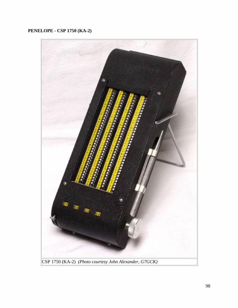
98
PENELOPE - CSP 1750 (KA-2)
CSP 1750 (KA-2) (Photo courtesy John Alexander, G7GCK)
99
The PENELOPE cryptosystem was designed to encrypt call signs and address groups used on
radio circuits, both Morse and Voice. System components included keying materials and either
of two associated devices designed for encrypting call signs and address groups in the form of
four character groups, which were composed of any combination of letters and digits. Dennis
Stapleton confirms the use of the CSP1750 in the early 1950's and Al Goodwin says it was used
into the 1960s. The is no example of this device aboard HAIDA.
OTP (One Time Pad)
In the RCN, the OTP was used to encode messages destined for smaller ships that could not
justify the cost of crypto equipment. Al Goodwin (former POTEL) confirms the use of the OTP
in HAIDA right from the Korean war era until the ship was paid off in October of 1963.
A one-time pad is essentially a pad of paper on which each page has a unique set of random
letters. The sender and receiver have identical pads. Each letter on the pad is used to determine a
single letter of the enciphered message. Since the letters on the pad are random, there is no
formula that can be determined by studying the letters. Assuming that the pad is not
compromised, and each page is used only once, then the OTP system is unbreakable. The
disadvantage of the OTP system is that a copy of the pad must be securely delivered to the
person on each end of the communication.
The OTP has not been distributed to RCN ships for quite some time now. It is believed that the
pad was abandoned sometime during the 1970's or even the 80s.
1.22 CODING OFFICE - DESCRIPTION OF EQUIPMENT - 1962
TSEC/KL-7 Off-Line Coding Unit
This was an 8 rotor off-line cipher machine code name ADONIS, and was similar to, but more
advanced than the famous German Enigma machine. It was used for the protection of exclusive
(off-line) traffic. The unit had the approximate dimensions of a medium sized portable typewriter
and was housed in an extruded aluminum carrying case which was painted in an olive drab,
khaki colour. Navy versions, were of course, navy grey and the hinged case lid opened from
front to rear. On the front of the KL7, there was a character counter to help keep track of the
number of characters in a message and a small lamp to illuminate the keyboard. Rotor #4, not
viewable, was maintained in a 'neutral' position. The Coding Office was fitted with two KL-7’s.
Crypto-variables such as rotor settings were referenced from a hard bound paper code book or
'flash' paper bound into a small booklet. The KL7's used aboard HAIDA were powered from a
120 volt 60 Hz source. In the RCN, a complete second rotor assembly was stored in a separate
box away from the machine. This assembly had the settings from the previous day and could
easily be substituted in the KL7 to decode a late arriving message from the previous day.
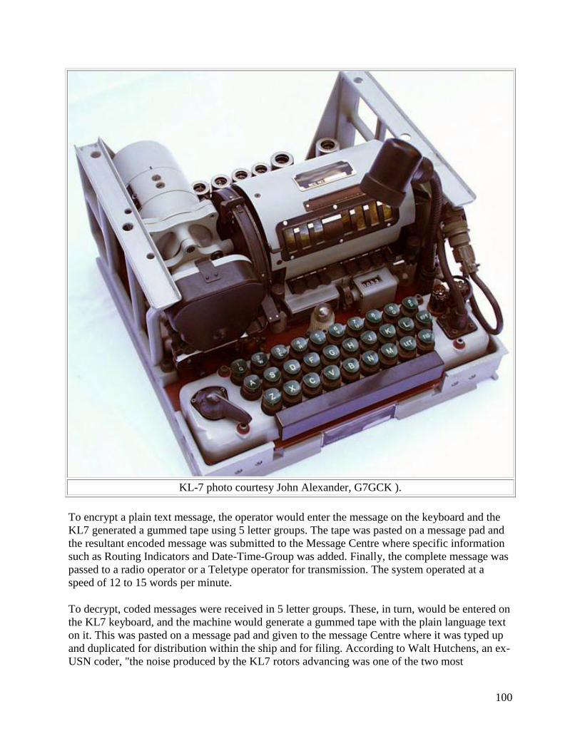
100
KL-7 photo courtesy John Alexander, G7GCK ).
To encrypt a plain text message, the operator would enter the message on the keyboard and the
KL7 generated a gummed tape using 5 letter groups. The tape was pasted on a message pad and
the resultant encoded message was submitted to the Message Centre where specific information
such as Routing Indicators and Date-Time-Group was added. Finally, the complete message was
passed to a radio operator or a Teletype operator for transmission. The system operated at a
speed of 12 to 15 words per minute.
To decrypt, coded messages were received in 5 letter groups. These, in turn, would be entered on
the KL7 keyboard, and the machine would generate a gummed tape with the plain language text
on it. This was pasted on a message pad and given to the message Centre where it was typed up
and duplicated for distribution within the ship and for filing. According to Walt Hutchens, an ex-
USN coder, "the noise produced by the KL7 rotors advancing was one of the two most
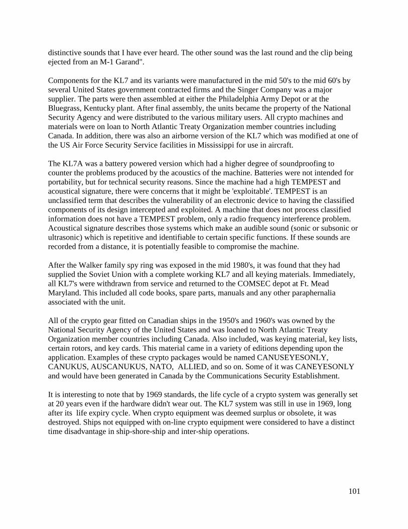
101
distinctive sounds that I have ever heard. The other sound was the last round and the clip being
ejected from an M-1 Garand".
Components for the KL7 and its variants were manufactured in the mid 50's to the mid 60's by
several United States government contracted firms and the Singer Company was a major
supplier. The parts were then assembled at either the Philadelphia Army Depot or at the
Bluegrass, Kentucky plant. After final assembly, the units became the property of the National
Security Agency and were distributed to the various military users. All crypto machines and
materials were on loan to North Atlantic Treaty Organization member countries including
Canada. In addition, there was also an airborne version of the KL7 which was modified at one of
the US Air Force Security Service facilities in Mississippi for use in aircraft.
The KL7A was a battery powered version which had a higher degree of soundproofing to
counter the problems produced by the acoustics of the machine. Batteries were not intended for
portability, but for technical security reasons. Since the machine had a high TEMPEST and
acoustical signature, there were concerns that it might be 'exploitable'. TEMPEST is an
unclassified term that describes the vulnerability of an electronic device to having the classified
components of its design intercepted and exploited. A machine that does not process classified
information does not have a TEMPEST problem, only a radio frequency interference problem.
Acoustical signature describes those systems which make an audible sound (sonic or subsonic or
ultrasonic) which is repetitive and identifiable to certain specific functions. If these sounds are
recorded from a distance, it is potentially feasible to compromise the machine.
After the Walker family spy ring was exposed in the mid 1980's, it was found that they had
supplied the Soviet Union with a complete working KL7 and all keying materials. Immediately,
all KL7's were withdrawn from service and returned to the COMSEC depot at Ft. Mead
Maryland. This included all code books, spare parts, manuals and any other paraphernalia
associated with the unit.
All of the crypto gear fitted on Canadian ships in the 1950's and 1960's was owned by the
National Security Agency of the United States and was loaned to North Atlantic Treaty
Organization member countries including Canada. Also included, was keying material, key lists,
certain rotors, and key cards. This material came in a variety of editions depending upon the
application. Examples of these crypto packages would be named CANUSEYESONLY,
CANUKUS, AUSCANUKUS, NATO, ALLIED, and so on. Some of it was CANEYESONLY
and would have been generated in Canada by the Communications Security Establishment.
It is interesting to note that by 1969 standards, the life cycle of a crypto system was generally set
at 20 years even if the hardware didn't wear out. The KL7 system was still in use in 1969, long
after its life expiry cycle. When crypto equipment was deemed surplus or obsolete, it was
destroyed. Ships not equipped with on-line crypto equipment were considered to have a distinct
time disadvantage in ship-shore-ship and inter-ship operations.
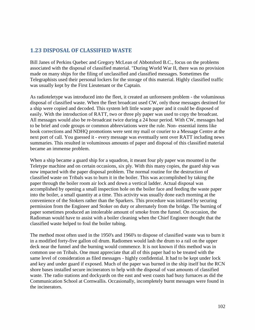
102
1.23 DISPOSAL OF CLASSIFIED WASTE
Bill Janes of Perkins Quebec and Gregory McLean of Abbotsford B.C., focus on the problems
associated with the disposal of classified material. "During World War II, there was no provision
made on many ships for the filing of unclassified and classified messages. Sometimes the
Telegraphists used their personal lockers for the storage of this material. Highly classified traffic
was usually kept by the First Lieutenant or the Captain.
As radioteletype was introduced into the fleet, it created an unforeseen problem - the voluminous
disposal of classified waste. When the fleet broadcast used CW, only those messages destined for
a ship were copied and decoded. This system left little waste paper and it could be disposed of
easily. With the introduction of RATT, two or three ply paper was used to copy the broadcast.
All messages would also be re-broadcast twice during a 24 hour period. With CW, messages had
to be brief and code groups or common abbreviations were the rule. Non- essential items like
book corrections and NDHQ promotions were sent my mail or courier to a Message Centre at the
next port of call. You guessed it - every message was eventually sent over RATT including news
summaries. This resulted in voluminous amounts of paper and disposal of this classified material
became an immense problem.
When a ship became a guard ship for a squadron, it meant four ply paper was mounted in the
Teletype machine and on certain occasions, six ply. With this many copies, the guard ship was
now impacted with the paper disposal problem. The normal routine for the destruction of
classified waste on Tribals was to burn it in the boiler. This was accomplished by taking the
paper through the boiler room air lock and down a vertical ladder. Actual disposal was
accomplished by opening a small inspection hole on the boiler face and feeding the waste paper
into the boiler, a small quantity at a time. This activity was usually done each morning at the
convenience of the Stokers rather than the Sparkers. This procedure was initiated by securing
permission from the Engineer and Stoker on duty or alternately from the bridge. The burning of
paper sometimes produced an intolerable amount of smoke from the funnel. On occasion, the
Radioman would have to assist with a boiler cleaning when the Chief Engineer thought that the
classified waste helped to foul the boiler tubing.
The method most often used in the 1950's and 1960's to dispose of classified waste was to burn it
in a modified forty-five gallon oil drum. Radiomen would lash the drum to a rail on the upper
deck near the funnel and the burning would commence. It is not known if this method was in
common use on Tribals. One must appreciate that all of this paper had to be treated with the
same level of consideration as filed messages - highly confidential. It had to be kept under lock
and key and under guard if exposed. Much of the paper was burned in the ship itself but the RCN
shore bases installed secure incinerators to help with the disposal of vast amounts of classified
waste. The radio stations and dockyards on the east and west coasts had busy furnaces as did the
Communication School at Cornwallis. Occasionally, incompletely burnt messages were found in
the incinerators.
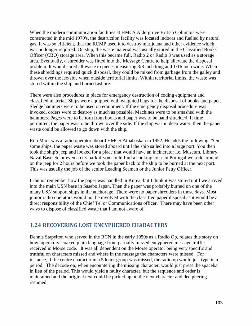
103
When the modern communication facilities at HMCS Aldergrove British Columbia were
constructed in the mid 1970's, the destruction facility was located indoors and fuelled by natural
gas. It was so efficient, that the RCMP used it to destroy marijuana and other evidence which
was no longer required. On ship, the waste material was usually stored in the Classified Books
Officer (CBO) storage area. When this became full, Radio 2 or Radio 3 was used as a storage
area. Eventually, a shredder was fitted into the Message Centre to help alleviate the disposal
problem. It would shred all waste to pieces measuring 3/8 inch long and 1/16 inch wide. When
these shreddings required quick disposal, they could be mixed from garbage from the galley and
thrown over the lee-side when outside territorial limits. Within territorial limits, the waste was
stored within the ship and burned ashore.
There were also procedures in place for emergency destruction of coding equipment and
classified material. Ships were equipped with weighted bags for the disposal of books and paper.
Sledge hammers were to be used on equipment. If the emergency disposal procedure was
invoked, orders were to destroy as much as possible. Machines were to be smashed with the
hammers. Pages were to be torn from books and paper was to be hand shredded. If time
permitted, the paper was to be thrown over the side. If the ship was in deep water, then the paper
waste could be allowed to go down with the ship.
Ron Mark was a radio operator aboard HMCS Athabaskan in 1952. He adds the following. “On
some ships, the paper waste was stored aboard until the ship sailed into a large port. You then
took the ship's jeep and looked for a place that would have an incinerator i.e. Museum, Library,
Naval Base etc or even a city park if you could find a cooking area. In Portugal we rode around
on the jeep for 2 hours before we took the paper back to the ship to be burned at the next port.
This was usually the job of the senior Leading Seaman or the Junior Petty Officer.
I cannot remember how the paper was handled in Korea, but I think it was stored until we arrived
into the main USN base in Sasebo Japan. Then the paper was probably burned on one of the
many USN support ships in the anchorage. There were no paper shredders in those days. Most
junior radio operators would not be involved with the classified paper disposal as it would be a
direct responsibility of the Chief Tel or Communications officer. There may have been other
ways to dispose of classified waste that I am not aware of".
1.24 RECOVERING LOST ENCYPHERED CHARACTERS
Dennis Stapelton who served in the RCN in the early 1950s as a Radio Op, relates this story on
how operators coaxed plain language from partially missed encyphered message traffic
received in Morse code. "It was all dependent on the Morse operator being very specific and
truthful on characters missed and where in the message the characters were missed. For
instance, if the centre character in a 5 letter group was missed, the radio op would just type in a
period. The decode op, when encountering the missing character, would just press the spacebar
in lieu of the period. This would yield a faulty character, but the sequence and order is
maintained and the original text could be picked up on the next character and deciphering
resumed.
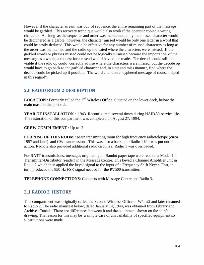
104
However if the character stream was out of sequence, the entire remaining part of the message
would be garbled. This recovery technique would also work if the operator copied a wrong
character. As long as the sequence and order was maintained, only the missed character would
be deciphered as a garble, however, the character missed would be only one letter in a word that
could be easily deduced. This would be effective for any number of missed characters as long as
the order was maintained and the radio op indicated where the characters were missed. If the
garbled words or phrases missed could not be logically surmised because the importance of the
message as a whole, a request for a resend would have to be made. The decode could still be
viable if the radio op could correctly advise where the characters were missed, but the decode op
would have to go back to the garbled character and, in a hit and miss manner, find where the
decode could be picked up if possible. The word count on encyphered message of course helped
in this regard".
2.0 RADIO ROOM 2 DESCRIPTION
LOCATION : Formerly called the 2nd
Wireless Office. Situated on the lower deck, below the
main mast on the port side.
YEAR OF INSTALLATION : 1943. Reconfigured several times during HAIDA's service life.
The restoration of this compartment was completed on August 27, 1994.
CREW COMPLEMENT : Up to 2
PURPOSE OF THIS ROOM : Main transmitting room for high frequency radioteletype (circa
1957 and later) and CW transmissions. This was also a backup to Radio 1 if it was put out if
action. Radio 2 also provided additional radio circuits if Radio 1 was overloaded.
For RATT transmissions, messages originating on Baudot paper tape were read on a Model 14
Transmitter-Distributor (reader) in the Message Centre. This keyed a Channel Amplifier unit in
Radio 2 which then applied the keyed signal to the input of a Frequency Shift Keyer. That, in
turn, produced the 850 Hz FSK signal needed for the PV500 transmitter.
TELEPHONE CONNECTIONS: Connects with Message Centre and Radio 3.
2.1 RADIO 2 HISTORY
This compartment was originally called the Second Wireless Office or W/T #2 and later renamed
to Radio 2. The radio manifest below, dated January 14, 1944, was obtained from Library and
Archives Canada. There are differences between it and the equipment shown on the ship’s
drawing. The reason for this may be a simple case of unavailability of specified equipment so
substitutions were made.
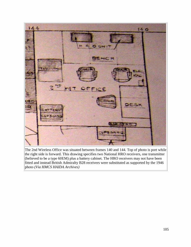
105
The 2nd Wireless Office was situated between frames 140 and 144. Top of photo is port while
the right side is forward. This drawing specifies two National HRO receivers, one transmitter
(believed to be a type 60EM) plus a battery cabinet. The HRO receivers may not have been
fitted and instead British Admiralty B28 receivers were substituted as supported by the 1946
photo (Via HMCS HAIDA Archives)
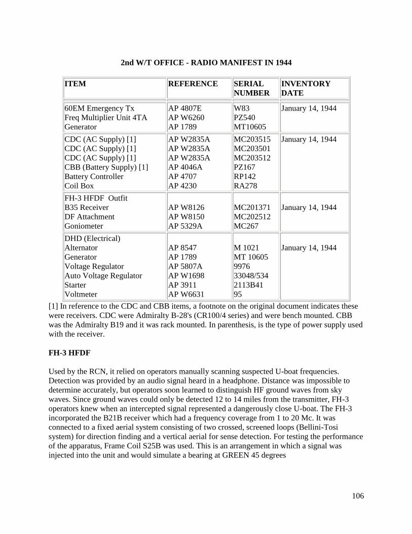
106
2nd W/T OFFICE - RADIO MANIFEST IN 1944
ITEM REFERENCE SERIAL
NUMBER
INVENTORY
DATE
60EM Emergency Tx
Freq Multiplier Unit 4TA
Generator
AP 4807E
AP W6260
AP 1789
W83
PZ540
MT10605
January 14, 1944
CDC (AC Supply) [1]
CDC (AC Supply) [1]
CDC (AC Supply) [1]
CBB (Battery Supply) [1]
Battery Controller
Coil Box
AP W2835A
AP W2835A
AP W2835A
AP 4046A
AP 4707
AP 4230
MC203515
MC203501
MC203512
PZ167
RP142
RA278
January 14, 1944
FH-3 HFDF Outfit
B35 Receiver
DF Attachment
Goniometer
AP W8126
AP W8150
AP 5329A
MC201371
MC202512
MC267
January 14, 1944
DHD (Electrical)
Alternator
Generator
Voltage Regulator
Auto Voltage Regulator
Starter
Voltmeter
AP 8547
AP 1789
AP 5807A
AP W1698
AP 3911
AP W6631
M 1021
MT 10605
9976
33048/534
2113B41
95
January 14, 1944
[1] In reference to the CDC and CBB items, a footnote on the original document indicates these
were receivers. CDC were Admiralty B-28's (CR100/4 series) and were bench mounted. CBB
was the Admiralty B19 and it was rack mounted. In parenthesis, is the type of power supply used
with the receiver.
FH-3 HFDF
Used by the RCN, it relied on operators manually scanning suspected U-boat frequencies.
Detection was provided by an audio signal heard in a headphone. Distance was impossible to
determine accurately, but operators soon learned to distinguish HF ground waves from sky
waves. Since ground waves could only be detected 12 to 14 miles from the transmitter, FH-3
operators knew when an intercepted signal represented a dangerously close U-boat. The FH-3
incorporated the B21B receiver which had a frequency coverage from 1 to 20 Mc. It was
connected to a fixed aerial system consisting of two crossed, screened loops (Bellini-Tosi
system) for direction finding and a vertical aerial for sense detection. For testing the performance
of the apparatus, Frame Coil S25B was used. This is an arrangement in which a signal was
injected into the unit and would simulate a bearing at GREEN 45 degrees
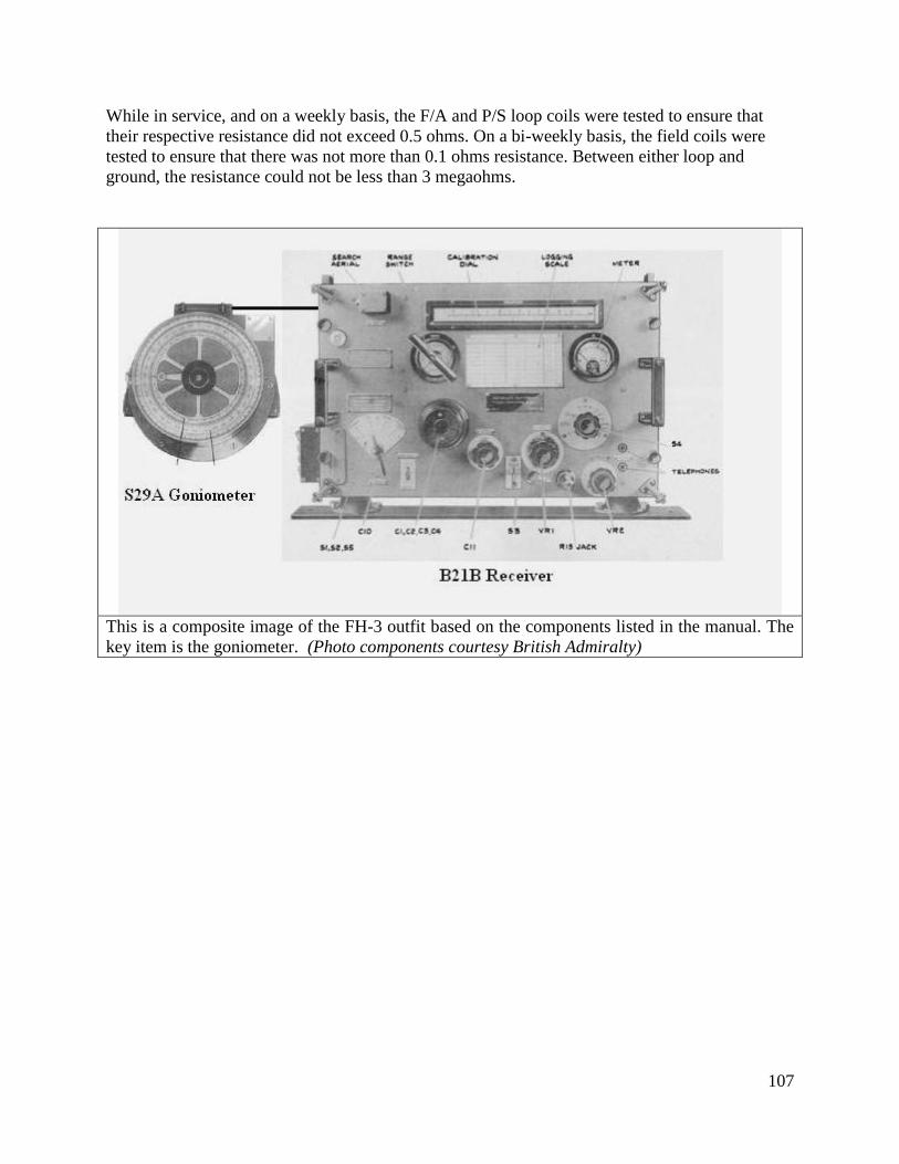
107
While in service, and on a weekly basis, the F/A and P/S loop coils were tested to ensure that
their respective resistance did not exceed 0.5 ohms. On a bi-weekly basis, the field coils were
tested to ensure that there was not more than 0.1 ohms resistance. Between either loop and
ground, the resistance could not be less than 3 megaohms.
This is a composite image of the FH-3 outfit based on the components listed in the manual. The
key item is the goniometer. (Photo components courtesy British Admiralty)
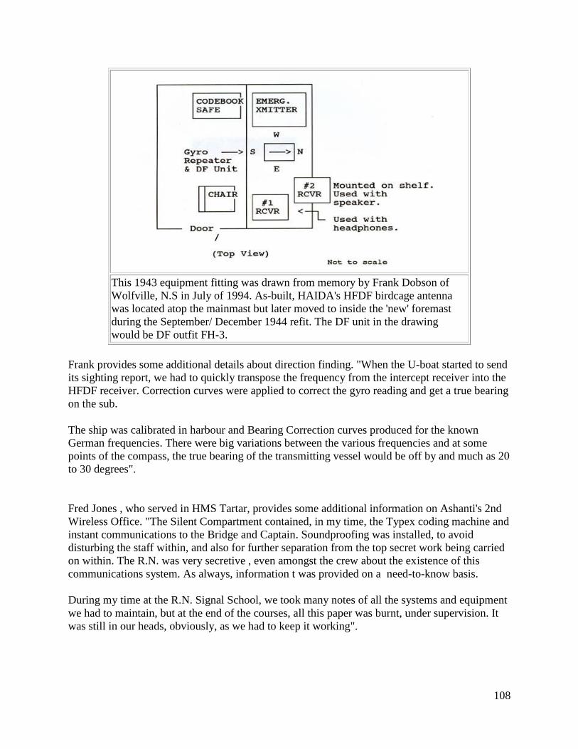
108
This 1943 equipment fitting was drawn from memory by Frank Dobson of
Wolfville, N.S in July of 1994. As-built, HAIDA's HFDF birdcage antenna
was located atop the mainmast but later moved to inside the 'new' foremast
during the September/ December 1944 refit. The DF unit in the drawing
would be DF outfit FH-3.
Frank provides some additional details about direction finding. "When the U-boat started to send
its sighting report, we had to quickly transpose the frequency from the intercept receiver into the
HFDF receiver. Correction curves were applied to correct the gyro reading and get a true bearing
on the sub.
The ship was calibrated in harbour and Bearing Correction curves produced for the known
German frequencies. There were big variations between the various frequencies and at some
points of the compass, the true bearing of the transmitting vessel would be off by and much as 20
to 30 degrees".
Fred Jones , who served in HMS Tartar, provides some additional information on Ashanti's 2nd
Wireless Office. "The Silent Compartment contained, in my time, the Typex coding machine and
instant communications to the Bridge and Captain. Soundproofing was installed, to avoid
disturbing the staff within, and also for further separation from the top secret work being carried
on within. The R.N. was very secretive , even amongst the crew about the existence of this
communications system. As always, information t was provided on a need-to-know basis.
During my time at the R.N. Signal School, we took many notes of all the systems and equipment
we had to maintain, but at the end of the courses, all this paper was burnt, under supervision. It
was still in our heads, obviously, as we had to keep it working".
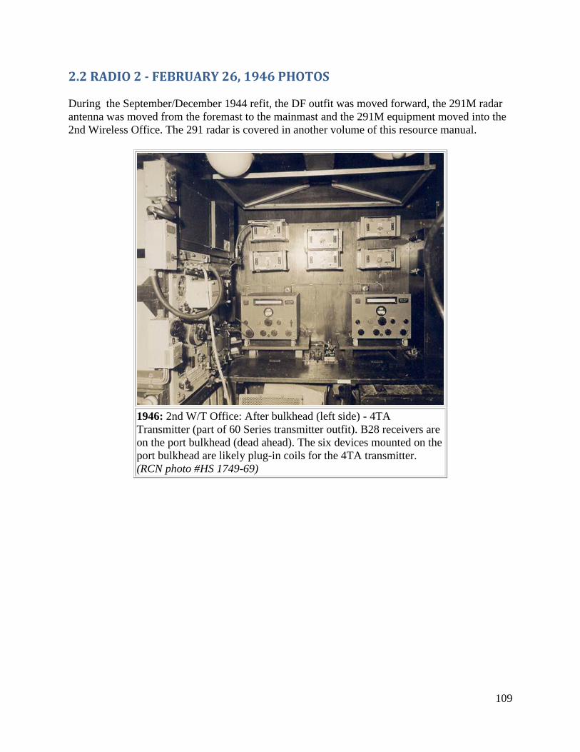
109
2.2 RADIO 2 - FEBRUARY 26, 1946 PHOTOS
During the September/December 1944 refit, the DF outfit was moved forward, the 291M radar
antenna was moved from the foremast to the mainmast and the 291M equipment moved into the
2nd Wireless Office. The 291 radar is covered in another volume of this resource manual.
1946: 2nd W/T Office: After bulkhead (left side) - 4TA
Transmitter (part of 60 Series transmitter outfit). B28 receivers are
on the port bulkhead (dead ahead). The six devices mounted on the
port bulkhead are likely plug-in coils for the 4TA transmitter.
(RCN photo #HS 1749-69)
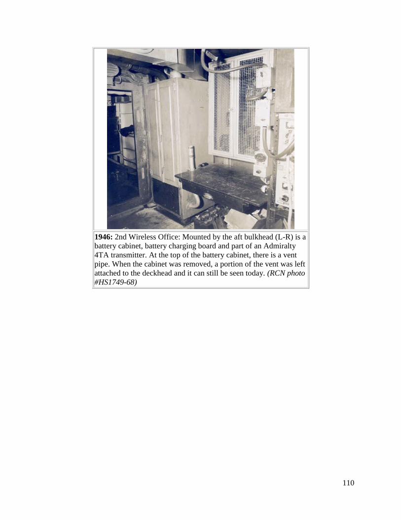
110
1946: 2nd Wireless Office: Mounted by the aft bulkhead (L-R) is a
battery cabinet, battery charging board and part of an Admiralty
4TA transmitter. At the top of the battery cabinet, there is a vent
pipe. When the cabinet was removed, a portion of the vent was left
attached to the deckhead and it can still be seen today. (RCN photo
#HS1749-68)
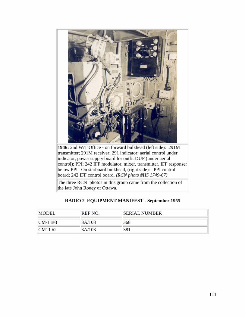
111
1946: 2nd W/T Office - on forward bulkhead (left side): 291M
transmitter; 291M receiver; 291 indicator; aerial control under
indicator, power supply board for outfit DUF (under aerial
control); PPI; 242 IFF modulator, mixer, transmitter, IFF responser
below PPI. On starboard bulkhead, (right side): PPI control
board; 242 IFF control board. (RCN photo #HS 1749-67)
The three RCN photos in this group came from the collection of
the late John Rouey of Ottawa.
RADIO 2 EQUIPMENT MANIFEST - September 1955
MODEL REF NO. SERIAL NUMBER
CM-11#3 3A/103 368
CM11 #2 3A/103 381
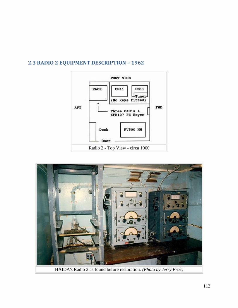
112
2.3 RADIO 2 EQUIPMENT DESCRIPTION – 1962
Radio 2 - Top View - circa 1960
HAIDA's Radio 2 as found before restoration. (Photo by Jerry Proc)
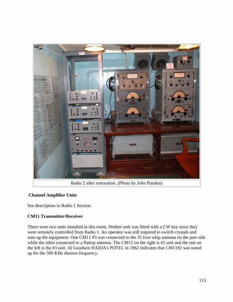
113
Radio 2 after restoration. (Photo by John Paszkat)
Channel Amplifier Units
See description in Radio 1 Section.
CM11 Transmitter/Receiver
There were two units installed in this room. Neither unit was fitted with a CW key since they
were remotely controlled from Radio 1. An operator was still required to switch crystals and
tune up the equipment. One CM11 #3 was connected to the 35 foot whip antenna on the port side
while the other connected to a flattop antenna. The CM11 on the right is #2 unit and the one on
the left is the #3 unit. Al Goodwin HAIDA's POTEL in 1962 indicates that CM11#2 was tuned
up for the 500 KHz distress frequency.
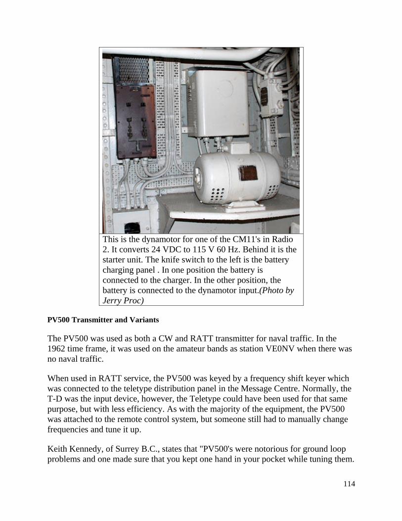
114
This is the dynamotor for one of the CM11's in Radio
2. It converts 24 VDC to 115 V 60 Hz. Behind it is the
starter unit. The knife switch to the left is the battery
charging panel . In one position the battery is
connected to the charger. In the other position, the
battery is connected to the dynamotor input.(Photo by
Jerry Proc)
PV500 Transmitter and Variants
The PV500 was used as both a CW and RATT transmitter for naval traffic. In the
1962 time frame, it was used on the amateur bands as station VE0NV when there was
no naval traffic.
When used in RATT service, the PV500 was keyed by a frequency shift keyer which
was connected to the teletype distribution panel in the Message Centre. Normally, the
T-D was the input device, however, the Teletype could have been used for that same
purpose, but with less efficiency. As with the majority of the equipment, the PV500
was attached to the remote control system, but someone still had to manually change
frequencies and tune it up.
Keith Kennedy, of Surrey B.C., states that "PV500's were notorious for ground loop
problems and one made sure that you kept one hand in your pocket while tuning them.
115
Placing your hand on the cabinet to brace yourself against the ships roll could result in
a really fine 'attention grabber' in the form of an AC buzz. Many Radiomen tuned the
PV500 HM2's by watching the power amplifier through the front panel window.
When the plate was cherry red but not white, the final stage was considered to be
tuned. As an additional tuning aid, a small fluorescent bulb was taped to the antenna
feed line and the final would be tuned for maximum brightness. On some PV500's, the
front bottom left power supply cover panel can be found somewhat dented. This was
normal and was caused by having to kick it there in order to ensure that the power
supply interlock engaged.
Since there was no drive level control on the PV500 HM2, there was excessive drive
at lower frequencies and insufficient drive at high frequencies. Multiplier stages had
to be detuned to obtain the desired drive levels. To reduce chirp on CW, the multiplier
stages were keyed while the oscillator was held on for the duration of a 'word'. This
reduced chirp to the first letter of each word sent and permitted the use of break-in
operation. In the PV500 HM3, there were design changes to overcome deficiencies of
the previous models. A driver stage and drive level control were added. Frequency
shift keying capability was added. In the previous models, there was a large power
loss in the trunking to the antenna, so the antenna tuner was removed from the
transmitter and was re-designed for remote operation".
The PV500 HM currently on display was acquired from HMCS Griffon Naval
Reserve Division in Thunder Bay Ontario, but HAIDA was fitted with the PV500
HM2 when she was paid off.
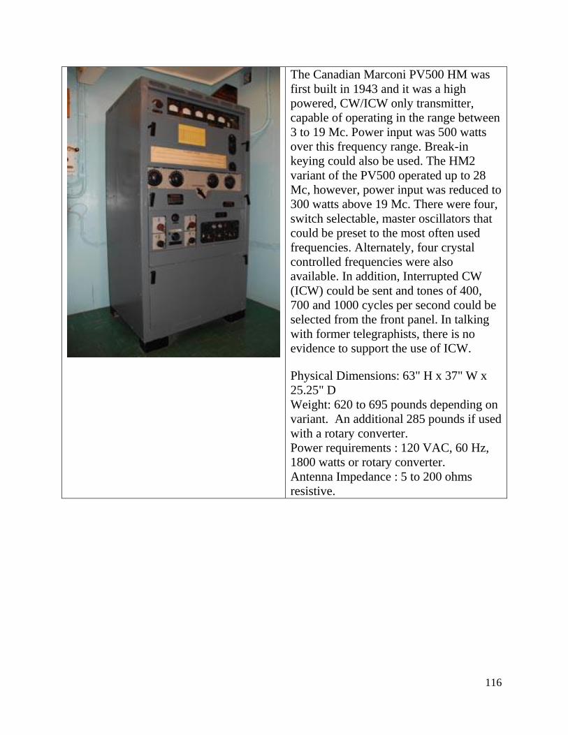
116
The Canadian Marconi PV500 HM was
first built in 1943 and it was a high
powered, CW/ICW only transmitter,
capable of operating in the range between
3 to 19 Mc. Power input was 500 watts
over this frequency range. Break-in
keying could also be used. The HM2
variant of the PV500 operated up to 28
Mc, however, power input was reduced to
300 watts above 19 Mc. There were four,
switch selectable, master oscillators that
could be preset to the most often used
frequencies. Alternately, four crystal
controlled frequencies were also
available. In addition, Interrupted CW
(ICW) could be sent and tones of 400,
700 and 1000 cycles per second could be
selected from the front panel. In talking
with former telegraphists, there is no
evidence to support the use of ICW.
Physical Dimensions: 63" H x 37" W x
25.25" D
Weight: 620 to 695 pounds depending on
variant. An additional 285 pounds if used
with a rotary converter.
Power requirements : 120 VAC, 60 Hz,
1800 watts or rotary converter.
Antenna Impedance : 5 to 200 ohms
resistive.
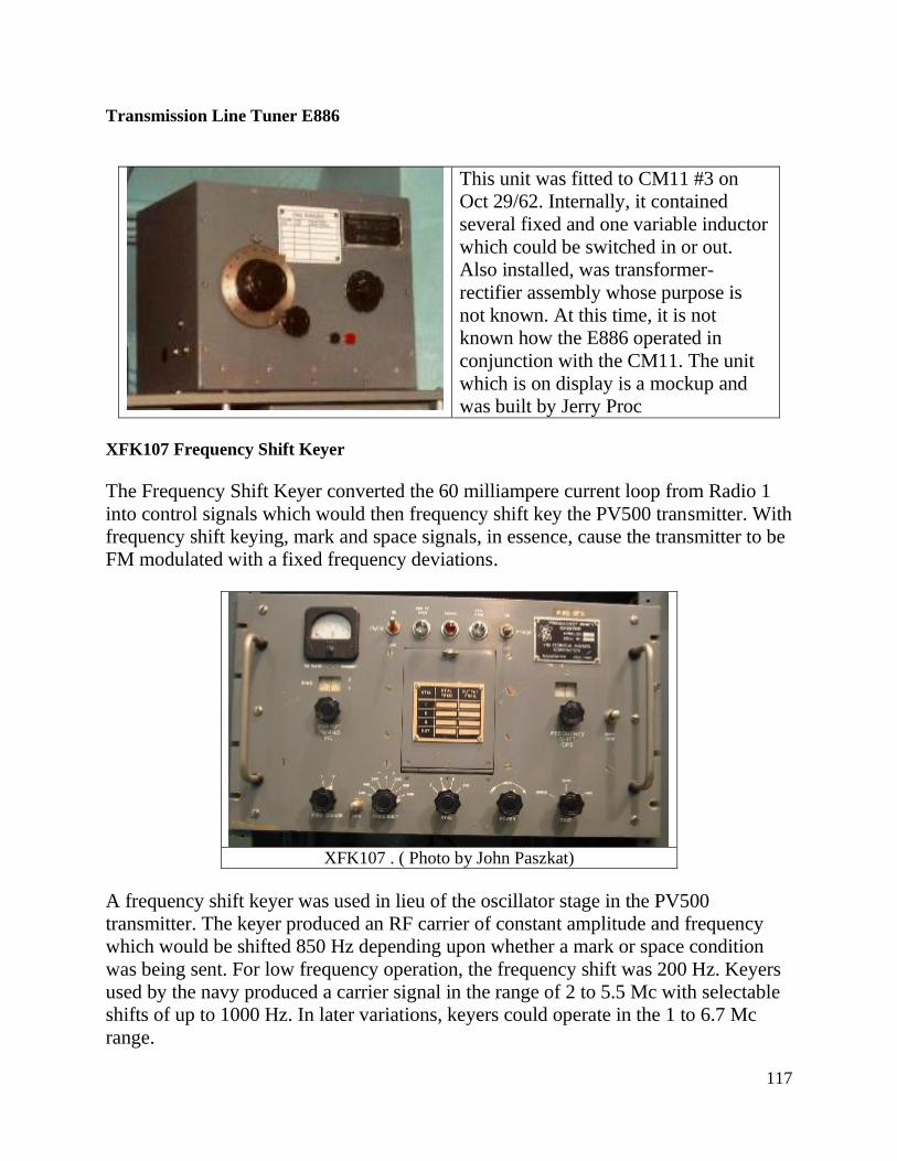
117
Transmission Line Tuner E886
This unit was fitted to CM11 #3 on
Oct 29/62. Internally, it contained
several fixed and one variable inductor
which could be switched in or out.
Also installed, was transformer-
rectifier assembly whose purpose is
not known. At this time, it is not
known how the E886 operated in
conjunction with the CM11. The unit
which is on display is a mockup and
was built by Jerry Proc
XFK107 Frequency Shift Keyer
The Frequency Shift Keyer converted the 60 milliampere current loop from Radio 1
into control signals which would then frequency shift key the PV500 transmitter. With
frequency shift keying, mark and space signals, in essence, cause the transmitter to be
FM modulated with a fixed frequency deviations.
XFK107 . ( Photo by John Paszkat)
A frequency shift keyer was used in lieu of the oscillator stage in the PV500
transmitter. The keyer produced an RF carrier of constant amplitude and frequency
which would be shifted 850 Hz depending upon whether a mark or space condition
was being sent. For low frequency operation, the frequency shift was 200 Hz. Keyers
used by the navy produced a carrier signal in the range of 2 to 5.5 Mc with selectable
shifts of up to 1000 Hz. In later variations, keyers could operate in the 1 to 6.7 Mc
range.
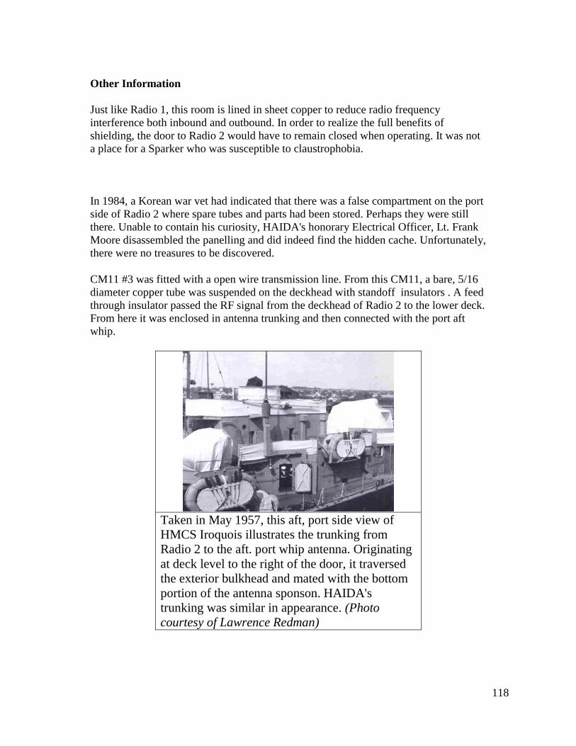
118
Other Information
Just like Radio 1, this room is lined in sheet copper to reduce radio frequency
interference both inbound and outbound. In order to realize the full benefits of
shielding, the door to Radio 2 would have to remain closed when operating. It was not
a place for a Sparker who was susceptible to claustrophobia.
In 1984, a Korean war vet had indicated that there was a false compartment on the port
side of Radio 2 where spare tubes and parts had been stored. Perhaps they were still
there. Unable to contain his curiosity, HAIDA's honorary Electrical Officer, Lt. Frank
Moore disassembled the panelling and did indeed find the hidden cache. Unfortunately,
there were no treasures to be discovered.
CM11 #3 was fitted with a open wire transmission line. From this CM11, a bare, 5/16
diameter copper tube was suspended on the deckhead with standoff insulators . A feed
through insulator passed the RF signal from the deckhead of Radio 2 to the lower deck.
From here it was enclosed in antenna trunking and then connected with the port aft
whip.
Taken in May 1957, this aft, port side view of
HMCS Iroquois illustrates the trunking from
Radio 2 to the aft. port whip antenna. Originating
at deck level to the right of the door, it traversed
the exterior bulkhead and mated with the bottom
portion of the antenna sponson. HAIDA's
trunking was similar in appearance. (Photo
courtesy of Lawrence Redman)
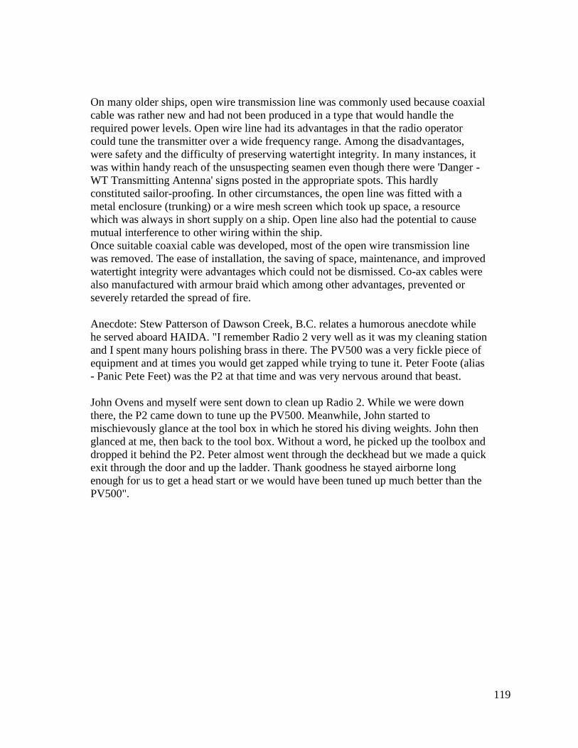
119
On many older ships, open wire transmission line was commonly used because coaxial
cable was rather new and had not been produced in a type that would handle the
required power levels. Open wire line had its advantages in that the radio operator
could tune the transmitter over a wide frequency range. Among the disadvantages,
were safety and the difficulty of preserving watertight integrity. In many instances, it
was within handy reach of the unsuspecting seamen even though there were 'Danger -
WT Transmitting Antenna' signs posted in the appropriate spots. This hardly
constituted sailor-proofing. In other circumstances, the open line was fitted with a
metal enclosure (trunking) or a wire mesh screen which took up space, a resource
which was always in short supply on a ship. Open line also had the potential to cause
mutual interference to other wiring within the ship.
Once suitable coaxial cable was developed, most of the open wire transmission line
was removed. The ease of installation, the saving of space, maintenance, and improved
watertight integrity were advantages which could not be dismissed. Co-ax cables were
also manufactured with armour braid which among other advantages, prevented or
severely retarded the spread of fire.
Anecdote: Stew Patterson of Dawson Creek, B.C. relates a humorous anecdote while
he served aboard HAIDA. "I remember Radio 2 very well as it was my cleaning station
and I spent many hours polishing brass in there. The PV500 was a very fickle piece of
equipment and at times you would get zapped while trying to tune it. Peter Foote (alias
- Panic Pete Feet) was the P2 at that time and was very nervous around that beast.
John Ovens and myself were sent down to clean up Radio 2. While we were down
there, the P2 came down to tune up the PV500. Meanwhile, John started to
mischievously glance at the tool box in which he stored his diving weights. John then
glanced at me, then back to the tool box. Without a word, he picked up the toolbox and
dropped it behind the P2. Peter almost went through the deckhead but we made a quick
exit through the door and up the ladder. Thank goodness he stayed airborne long
enough for us to get a head start or we would have been tuned up much better than the
PV500".
120
3.0 RADIO ROOM 3
LOCATION : Port side, flag deck, below lattice mast.
YEAR OF INSTALLATION : 1950. Restored May 26, 1996.
CREW COMPLEMENT : None. This room was normally unmanned and remotely controlled
unless frequencies had to be changed and equipment tuned up. The UHF equipment in this room
could be locally controlled under emergency conditions.
PURPOSE OF THIS ROOM : It was purely an equipment room and provided four additional
UHF circuits.
TELEPHONE CONNECTIONS: Connects with Radio 2 and Message Centre.
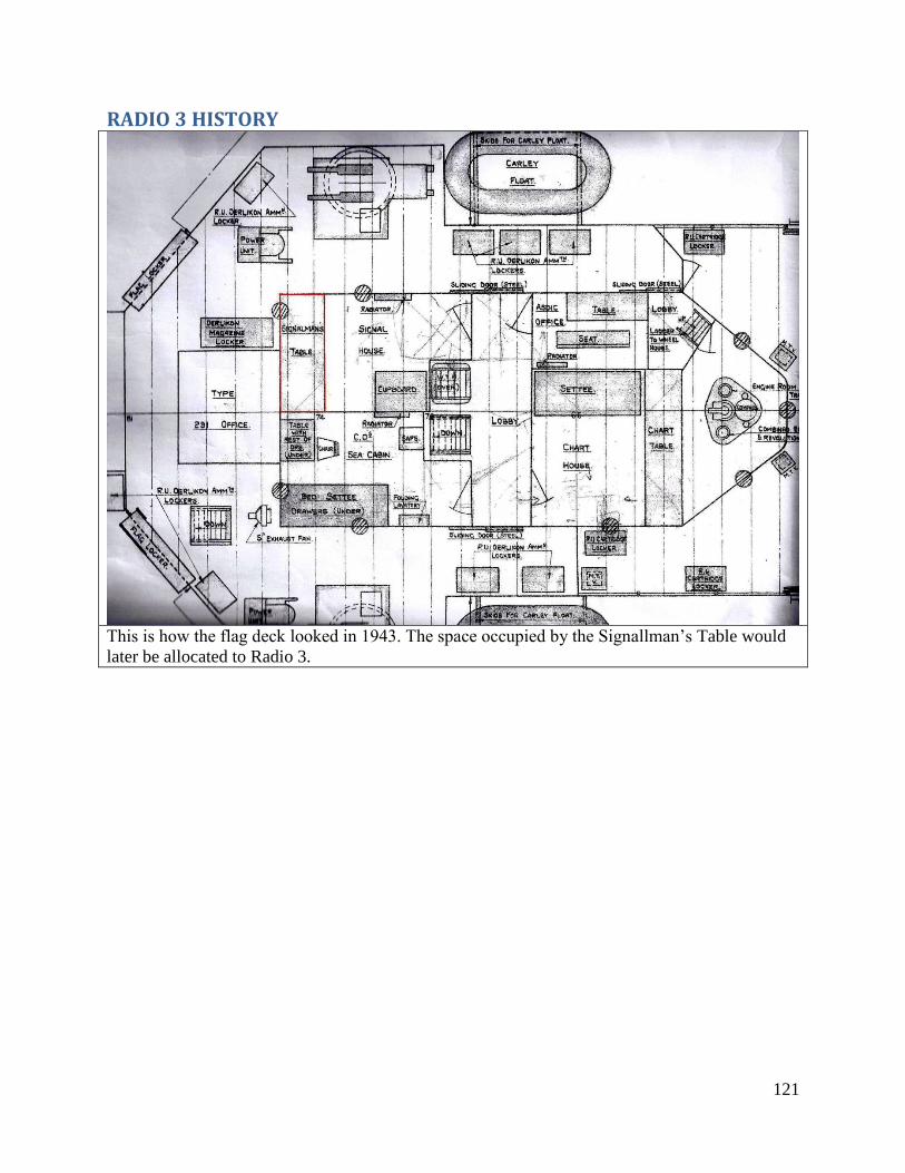
121
RADIO 3 HISTORY
This is how the flag deck looked in 1943. The space occupied by the Signallman’s Table would
later be allocated to Radio 3.
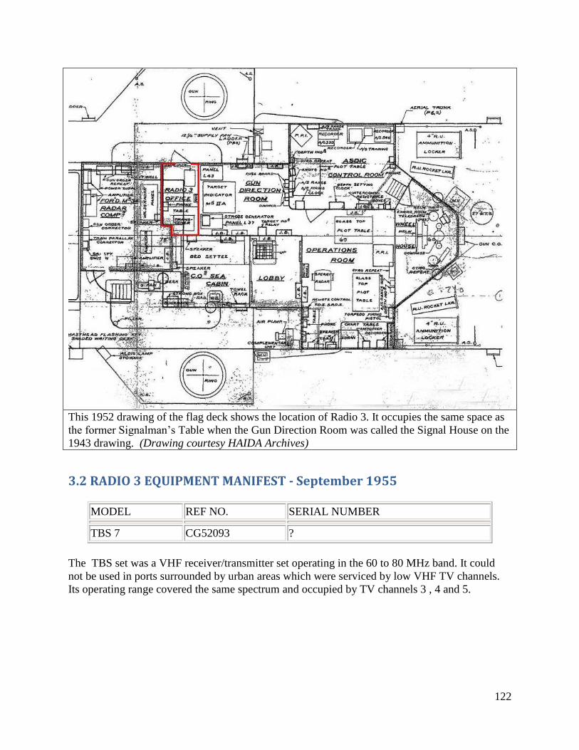
122
This 1952 drawing of the flag deck shows the location of Radio 3. It occupies the same space as
the former Signalman’s Table when the Gun Direction Room was called the Signal House on the
1943 drawing. (Drawing courtesy HAIDA Archives)
3.2 RADIO 3 EQUIPMENT MANIFEST - September 1955
MODEL REF NO. SERIAL NUMBER
TBS 7 CG52093 ?
The TBS set was a VHF receiver/transmitter set operating in the 60 to 80 MHz band. It could
not be used in ports surrounded by urban areas which were serviced by low VHF TV channels.
Its operating range covered the same spectrum and occupied by TV channels 3 , 4 and 5.
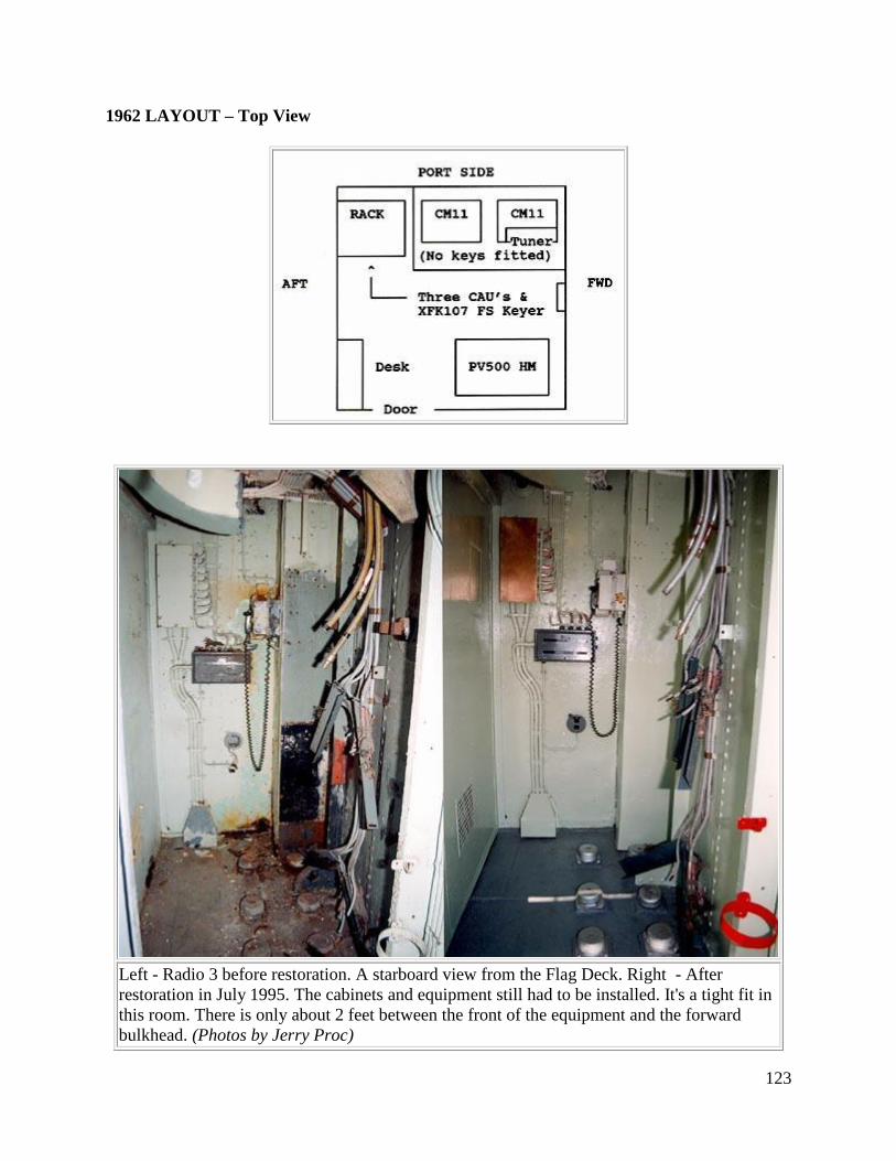
123
1962 LAYOUT – Top View
Left - Radio 3 before restoration. A starboard view from the Flag Deck. Right - After
restoration in July 1995. The cabinets and equipment still had to be installed. It's a tight fit in
this room. There is only about 2 feet between the front of the equipment and the forward
bulkhead. (Photos by Jerry Proc)
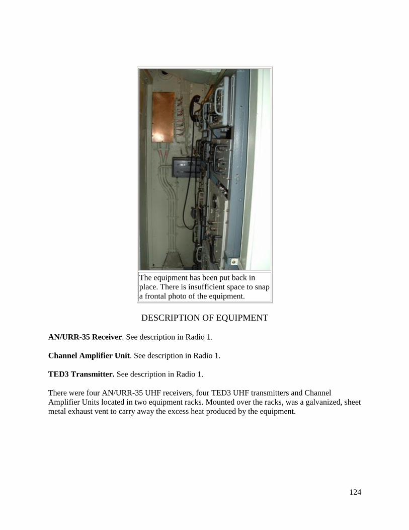
124
The equipment has been put back in
place. There is insufficient space to snap
a frontal photo of the equipment.
DESCRIPTION OF EQUIPMENT
AN/URR-35 Receiver. See description in Radio 1.
Channel Amplifier Unit. See description in Radio 1.
TED3 Transmitter. See description in Radio 1.
There were four AN/URR-35 UHF receivers, four TED3 UHF transmitters and Channel
Amplifier Units located in two equipment racks. Mounted over the racks, was a galvanized, sheet
metal exhaust vent to carry away the excess heat produced by the equipment.
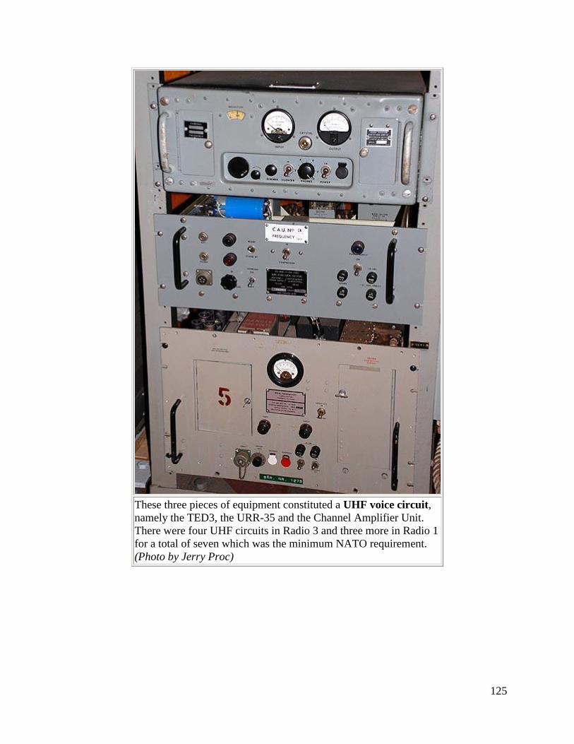
125
These three pieces of equipment constituted a UHF voice circuit,
namely the TED3, the URR-35 and the Channel Amplifier Unit.
There were four UHF circuits in Radio 3 and three more in Radio 1
for a total of seven which was the minimum NATO requirement.
(Photo by Jerry Proc)
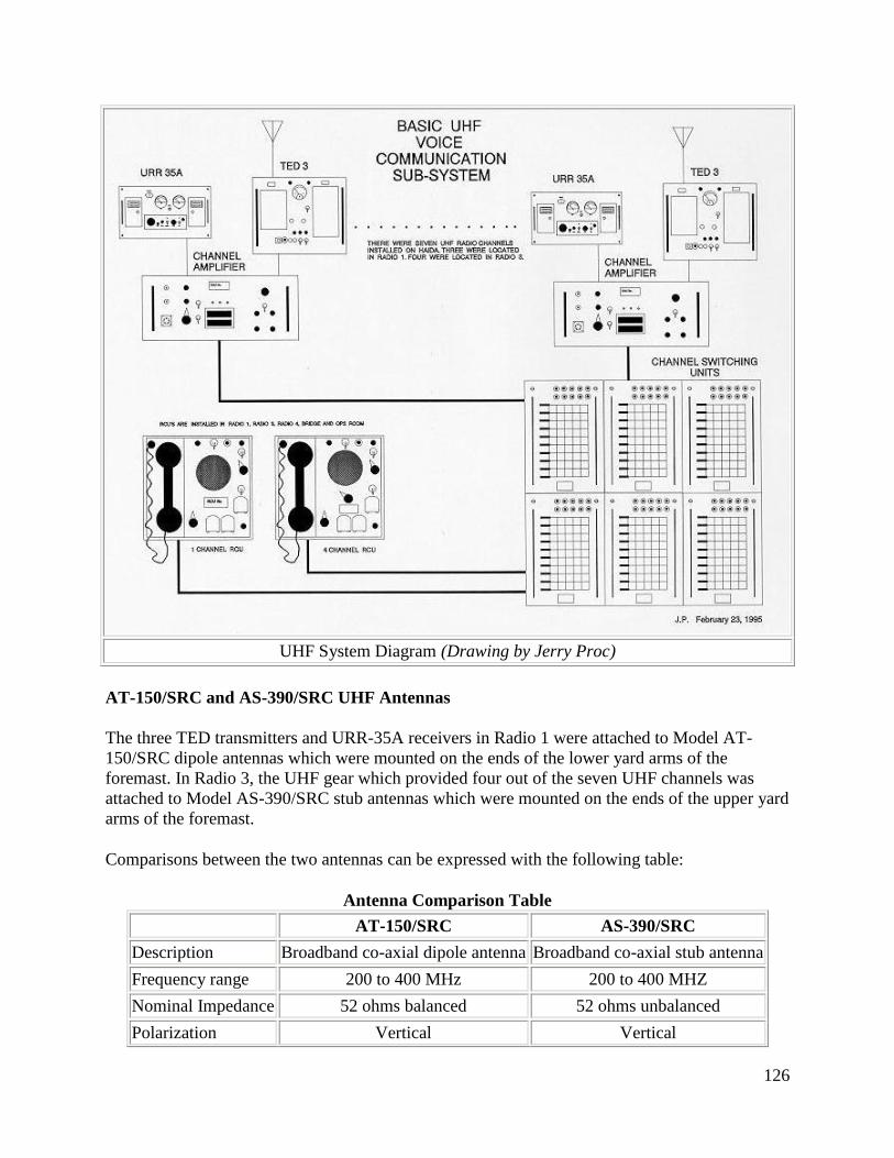
126
UHF System Diagram (Drawing by Jerry Proc)
AT-150/SRC and AS-390/SRC UHF Antennas
The three TED transmitters and URR-35A receivers in Radio 1 were attached to Model AT-
150/SRC dipole antennas which were mounted on the ends of the lower yard arms of the
foremast. In Radio 3, the UHF gear which provided four out of the seven UHF channels was
attached to Model AS-390/SRC stub antennas which were mounted on the ends of the upper yard
arms of the foremast.
Comparisons between the two antennas can be expressed with the following table:
Antenna Comparison Table
AT-150/SRC AS-390/SRC
Description Broadband co-axial dipole antenna Broadband co-axial stub antenna
Frequency range 200 to 400 MHz 200 to 400 MHZ
Nominal Impedance 52 ohms balanced 52 ohms unbalanced
Polarization Vertical Vertical
127
Power Input 300 watts maximum 300 watts maximum
Manufacturer Technical Appliance, Sherburne
NY or Bird Electronic
Bird Electronic,
Cleveland Ohio
Alternate Name AS-5042/URC AS-5041/URC
When at sea and in exercises, at least six, if not all seven, UHF circuits were in use all the time,
so there wasn't much opportunity to select which circuit would go to which antenna, except when
first setting up before sailing. The radiomen knew which antennas gave the best coverage, and
there were many factors that entered into this, including the mast shadow and the radiation
pattern of the antenna itself. When time was available, and it seldom was, an aircraft and other
ships were employed in order to construct a pattern for each antenna. Given the knowledge that
was available to the PO Tel, and the COMMO or OPSO, the most important circuits would be
assigned to the best antennas (eg PRITAC, and CIP(P). The antenna with the most suitable
pattern would be assigned to the air control circuits such as ASP(P). As the voyage went on, or
as the exercise progressed, there would be frequent changes of the COMPLAN, plus equipment
breakdowns, so that circuits would get moved around from one transmitter to another, and the
best constructed arrangement would soon be sacrificed to expediency. HAIDA was the first ship
in the RCN to be fitted with UHF capability.
4.0 RADIO 4 DESCRIPTION
LOCATION : Located on starboard side below the lattice mast.
YEAR OF INSTALLATION : Before 1956. Restored to 1962 configuration on Aug 1, 1993.
CREW COMPLEMENT : 2 - Anyone working in this room would have to be cleared for top
security.
PURPOSE OF THIS ROOM:
This was the electronic warfare room but mostly referred to as simply "Radio 4". It was capable
of providing direction finding services in the MF radio bands, plus the interception of radar
transmissions in the super high frequency (SHF) bands. Another function was for monitoring and
recording of tactical HF radio traffic using a Hammarlund general coverage receiver and tape
recorder.
Crew were provided with two-way high frequency communications between Electronic Warfare
Rooms on other ships. .
TELEPHONE CONNECTIONS: Connects to Radio 1, the OPS room and the bridge.
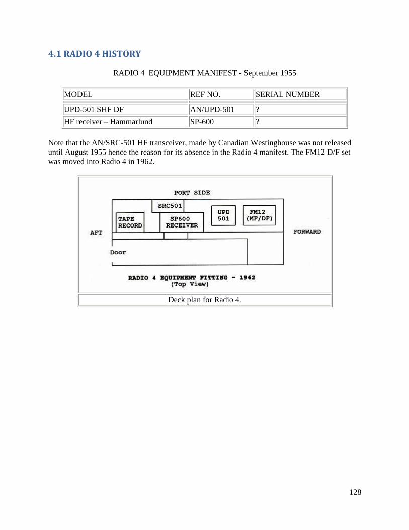
128
4.1 RADIO 4 HISTORY
RADIO 4 EQUIPMENT MANIFEST - September 1955
MODEL REF NO. SERIAL NUMBER
UPD-501 SHF DF AN/UPD-501 ?
HF receiver – Hammarlund SP-600 ?
Note that the AN/SRC-501 HF transceiver, made by Canadian Westinghouse was not released
until August 1955 hence the reason for its absence in the Radio 4 manifest. The FM12 D/F set
was moved into Radio 4 in 1962.
Deck plan for Radio 4.
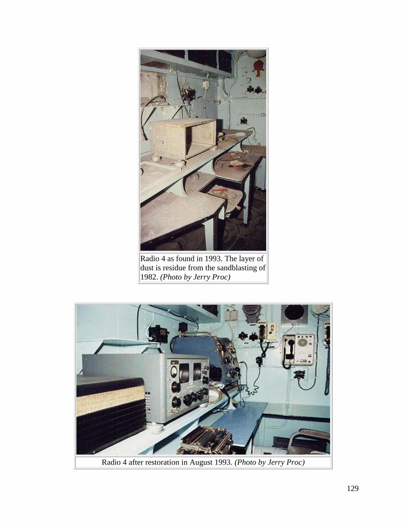
129
Radio 4 as found in 1993. The layer of
dust is residue from the sandblasting of
1982. (Photo by Jerry Proc)
Radio 4 after restoration in August 1993. (Photo by Jerry Proc)
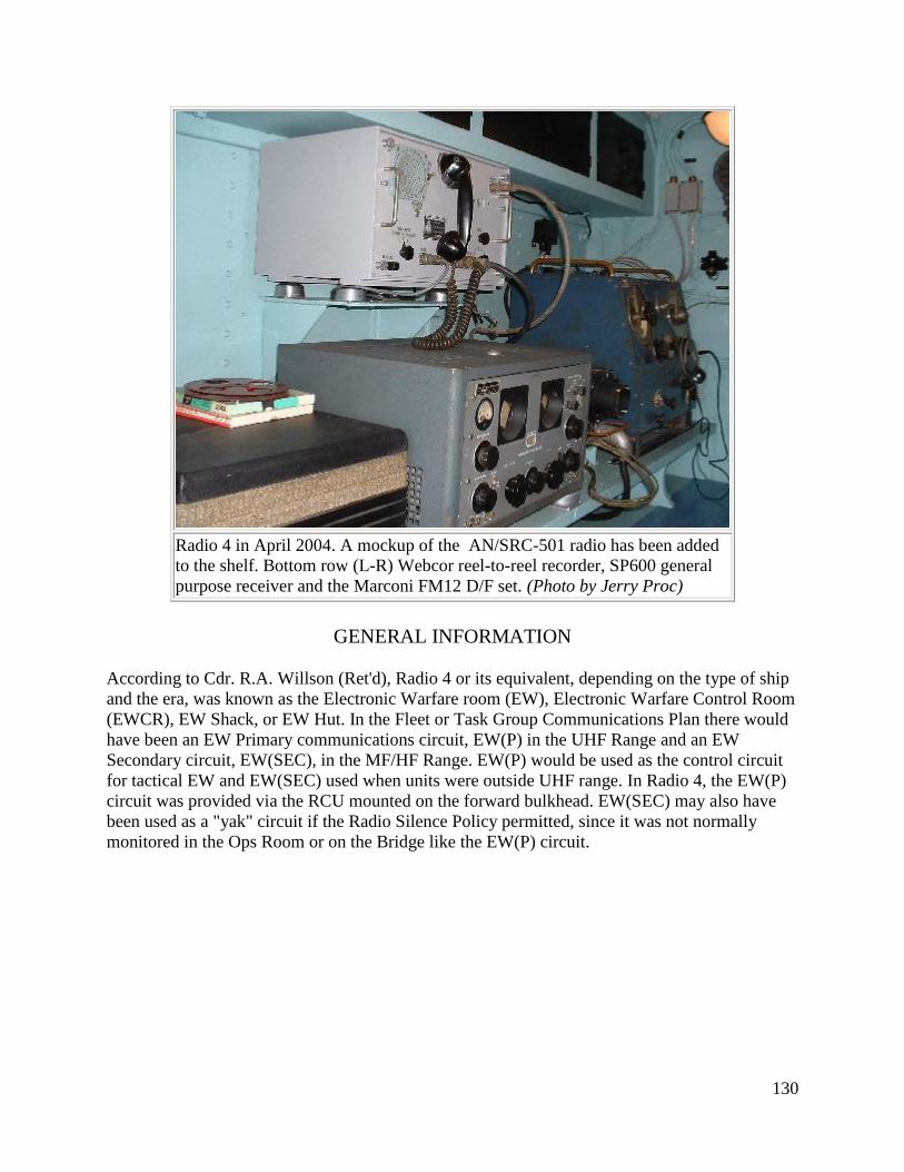
130
Radio 4 in April 2004. A mockup of the AN/SRC-501 radio has been added
to the shelf. Bottom row (L-R) Webcor reel-to-reel recorder, SP600 general
purpose receiver and the Marconi FM12 D/F set. (Photo by Jerry Proc)
GENERAL INFORMATION
According to Cdr. R.A. Willson (Ret'd), Radio 4 or its equivalent, depending on the type of ship
and the era, was known as the Electronic Warfare room (EW), Electronic Warfare Control Room
(EWCR), EW Shack, or EW Hut. In the Fleet or Task Group Communications Plan there would
have been an EW Primary communications circuit, EW(P) in the UHF Range and an EW
Secondary circuit, EW(SEC), in the MF/HF Range. EW(P) would be used as the control circuit
for tactical EW and EW(SEC) used when units were outside UHF range. In Radio 4, the EW(P)
circuit was provided via the RCU mounted on the forward bulkhead. EW(SEC) may also have
been used as a "yak" circuit if the Radio Silence Policy permitted, since it was not normally
monitored in the Ops Room or on the Bridge like the EW(P) circuit.
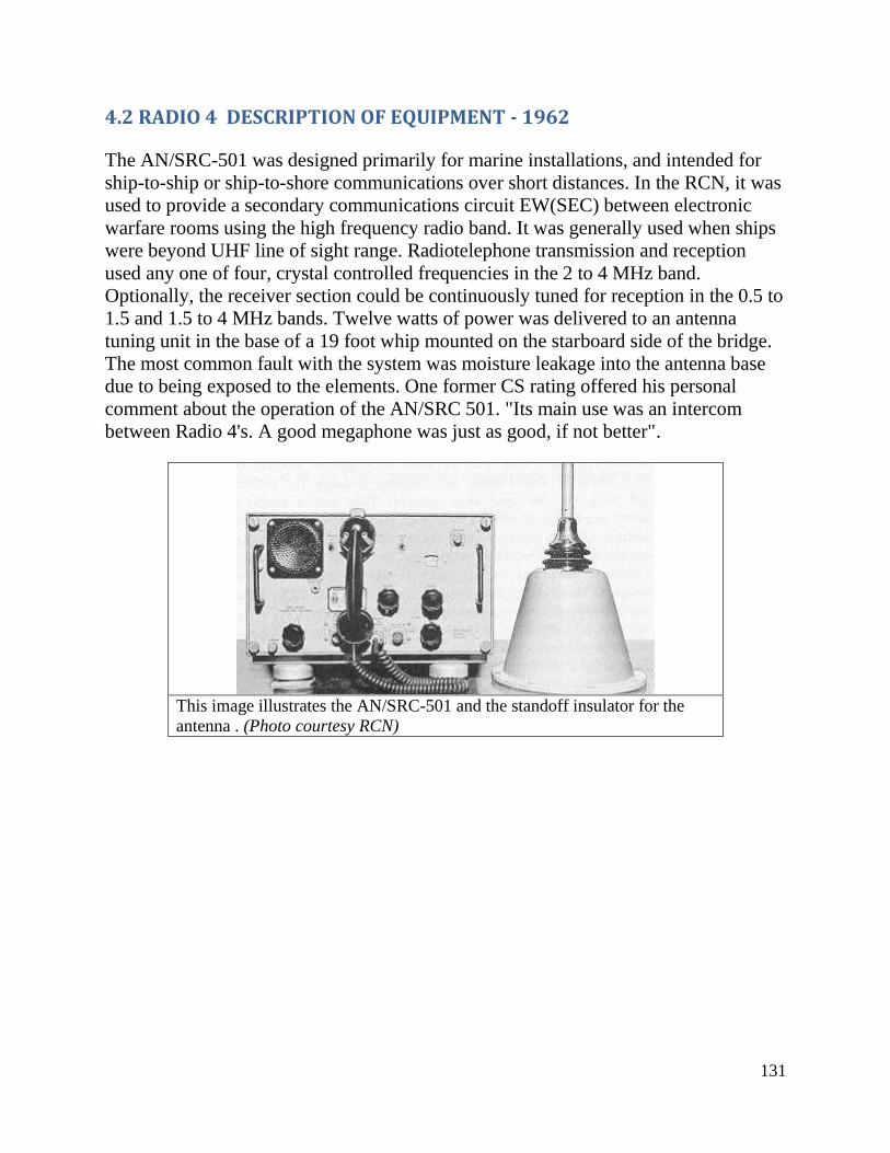
131
4.2 RADIO 4 DESCRIPTION OF EQUIPMENT - 1962
The AN/SRC-501 was designed primarily for marine installations, and intended for
ship-to-ship or ship-to-shore communications over short distances. In the RCN, it was
used to provide a secondary communications circuit EW(SEC) between electronic
warfare rooms using the high frequency radio band. It was generally used when ships
were beyond UHF line of sight range. Radiotelephone transmission and reception
used any one of four, crystal controlled frequencies in the 2 to 4 MHz band.
Optionally, the receiver section could be continuously tuned for reception in the 0.5 to
1.5 and 1.5 to 4 MHz bands. Twelve watts of power was delivered to an antenna
tuning unit in the base of a 19 foot whip mounted on the starboard side of the bridge.
The most common fault with the system was moisture leakage into the antenna base
due to being exposed to the elements. One former CS rating offered his personal
comment about the operation of the AN/SRC 501. "Its main use was an intercom
between Radio 4's. A good megaphone was just as good, if not better".
This image illustrates the AN/SRC-501 and the standoff insulator for the
antenna . (Photo courtesy RCN)
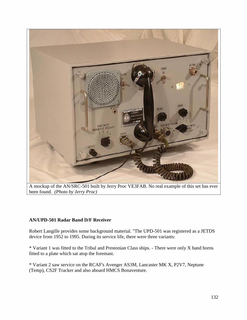
132
A mockup of the AN/SRC-501 built by Jerry Proc VE3FAB. No real example of this set has ever
been found. (Photo by Jerry Proc)
AN/UPD-501 Radar Band D/F Receiver
Robert Langille provides some background material. "The UPD-501 was registered as a JETDS
device from 1952 to 1995. During its service life, there were three variants:
* Variant 1 was fitted to the Tribal and Prestonian Class ships. - There were only X band horns
fitted to a plate which sat atop the foremast.
* Variant 2 saw service on the RCAF's Avenger AS3M, Lancaster MK X, P2V7, Neptune
(Temp), CS2F Tracker and also aboard HMCS Bonaventure.
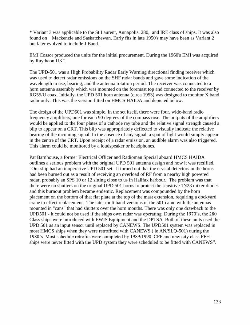
133
* Variant 3 was applicable to the St Laurent, Annapolis, 280, and IRE class of ships. It was also
found on Mackenzie and Saskatchewan. Early fits in late 1950's may have been as Variant 2
but later evolved to include J Band.
EMI Cossor produced the units for the initial procurement. During the 1960's EMI was acquired
by Raytheon UK".
The UPD-501 was a High Probability Radar Early Warning directional finding receiver which
was used to detect radar emissions on the SHF radar bands and gave some indication of the
wavelength in use, bearing, and the antenna rotation period. The receiver was connected to a
horn antenna assembly which was mounted on the foremast top and connected to the receiver by
RG55/U coax. Initially, the UPD 501 horn antenna (circa 1953) was designed to monitor X band
radar only. This was the version fitted on HMCS HAIDA and depicted below.
The design of the UPD501 was simple. In the set itself, there were four, wide-band radio
frequency amplifiers, one for each 90 degrees of the compass rose. The outputs of the amplifiers
would be applied to the four plates of a cathode ray tube and the relative signal strength caused a
blip to appear on a CRT. This blip was appropriately deflected to visually indicate the relative
bearing of the incoming signal. In the absence of any signal, a spot of light would simply appear
in the centre of the CRT. Upon receipt of a radar emission, an audible alarm was also triggered.
This alarm could be monitored by a loudspeaker or headphones.
Pat Barnhouse, a former Electrical Officer and Radioman Special aboard HMCS HAIDA
outlines a serious problem with the original UPD 501 antenna design and how it was rectified.
"Our ship had an inoperative UPD 501 set. It turned out that the crystal detectors in the horns
had been burned out as a result of receiving an overload of RF from a nearby high powered
radar, probably an SPS 10 or 12 sitting close to us in Halifax harbour. The problem was that
there were no shutters on the original UPD 501 horns to protect the sensitive 1N23 mixer diodes
and this burnout problem became endemic. Replacement was compounded by the horn
placement on the bottom of that flat plate at the top of the mast extension, requiring a dockyard
crane to effect replacement. The later multiband versions of the 501 came with the antennas
mounted in "cans" that had shutters over the horn mouths. There was only one drawback to the
UPD501 - it could not be used if the ships own radar was operating. During the 1970’s, the 280
Class ships were introduced with EWIS Equipment and the DPTSA. Both of these units used the
UPD 501 as an input sensor until replaced by CANEWS. The UPD501 system was replaced in
most HMCS ships when they were retrofitted with CANEWS ( ie AN/SLQ-501) during the
1980’s. Most schedule retrofits were completed by 1989/1990. CPF and new city class FFH
ships were never fitted with the UPD system they were scheduled to be fitted with CANEWS”.
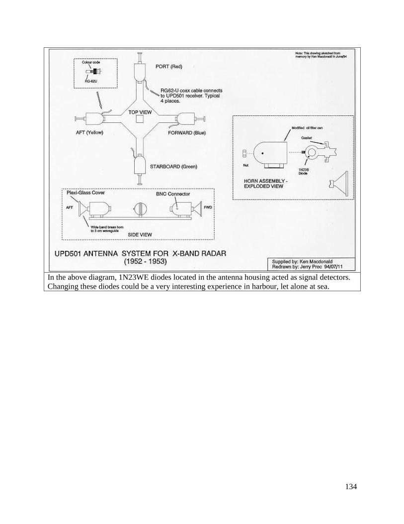
134
In the above diagram, 1N23WE diodes located in the antenna housing acted as signal detectors.
Changing these diodes could be a very interesting experience in harbour, let alone at sea.
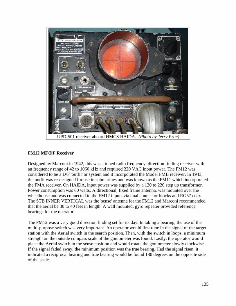
135
UPD-501 receiver aboard HMCS HAIDA. (Photo by Jerry Proc)
FM12 MF/DF Receiver
Designed by Marconi in 1942, this was a tuned radio frequency, direction finding receiver with
an frequency range of 42 to 1060 kHz and required 220 VAC input power. The FM12 was
considered to be a D/F 'outfit' or system and it incorporated the Model FMB receiver. In 1943,
the outfit was re-designed for use in submarines and was known as the FM11 which incorporated
the FMA receiver. On HAIDA, input power was supplied by a 120 to 220 step up transformer.
Power consumption was 60 watts. A directional, fixed frame antenna, was mounted over the
wheelhouse and was connected to the FM12 inputs via dual connector blocks and RG57 coax.
The STB INNER VERTICAL was the 'sense' antenna for the FM12 and Marconi recommended
that the aerial be 30 to 40 feet in length. A wall mounted, gyro repeater provided reference
bearings for the operator.
The FM12 was a very good direction finding set for its day. In taking a bearing, the use of the
multi-purpose switch was very important. An operator would first tune in the signal of the target
station with the Aerial switch in the search position. Then, with the switch in loops, a minimum
strength on the outside compass scale of the goniometer was found. Lastly, the operator would
place the Aerial switch in the sense position and would rotate the goniometer slowly clockwise.
If the signal faded away, the minimum position was the true bearing. Had the signal risen, it
indicated a reciprocal bearing and true bearing would be found 180 degrees on the opposite side
of the scale.
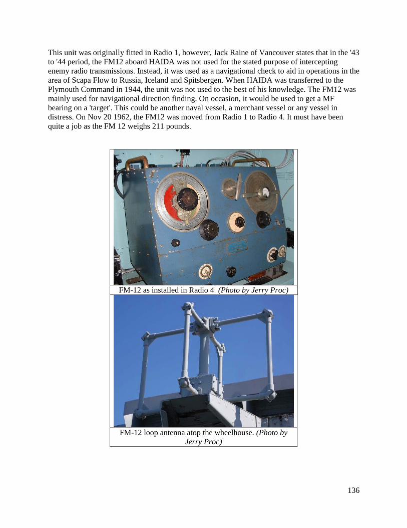
136
This unit was originally fitted in Radio 1, however, Jack Raine of Vancouver states that in the '43
to '44 period, the FM12 aboard HAIDA was not used for the stated purpose of intercepting
enemy radio transmissions. Instead, it was used as a navigational check to aid in operations in the
area of Scapa Flow to Russia, Iceland and Spitsbergen. When HAIDA was transferred to the
Plymouth Command in 1944, the unit was not used to the best of his knowledge. The FM12 was
mainly used for navigational direction finding. On occasion, it would be used to get a MF
bearing on a 'target'. This could be another naval vessel, a merchant vessel or any vessel in
distress. On Nov 20 1962, the FM12 was moved from Radio 1 to Radio 4. It must have been
quite a job as the FM 12 weighs 211 pounds.
FM-12 as installed in Radio 4 (Photo by Jerry Proc)
FM-12 loop antenna atop the wheelhouse. (Photo by
Jerry Proc)
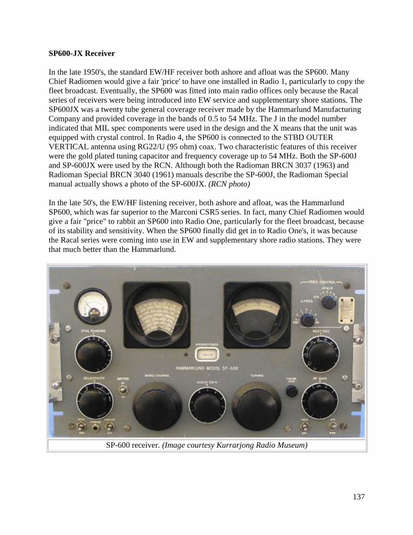
137
SP600-JX Receiver
In the late 1950's, the standard EW/HF receiver both ashore and afloat was the SP600. Many
Chief Radiomen would give a fair 'price' to have one installed in Radio 1, particularly to copy the
fleet broadcast. Eventually, the SP600 was fitted into main radio offices only because the Racal
series of receivers were being introduced into EW service and supplementary shore stations. The
SP600JX was a twenty tube general coverage receiver made by the Hammarlund Manufacturing
Company and provided coverage in the bands of 0.5 to 54 MHz. The J in the model number
indicated that MIL spec components were used in the design and the X means that the unit was
equipped with crystal control. In Radio 4, the SP600 is connected to the STBD OUTER
VERTICAL antenna using RG22/U (95 ohm) coax. Two characteristic features of this receiver
were the gold plated tuning capacitor and frequency coverage up to 54 MHz. Both the SP-600J
and SP-600JX were used by the RCN. Although both the Radioman BRCN 3037 (1963) and
Radioman Special BRCN 3040 (1961) manuals describe the SP-600J, the Radioman Special
manual actually shows a photo of the SP-600JX. (RCN photo)
In the late 50's, the EW/HF listening receiver, both ashore and afloat, was the Hammarlund
SP600, which was far superior to the Marconi CSR5 series. In fact, many Chief Radiomen would
give a fair "price" to rabbit an SP600 into Radio One, particularly for the fleet broadcast, because
of its stability and sensitivity. When the SP600 finally did get in to Radio One's, it was because
the Racal series were coming into use in EW and supplementary shore radio stations. They were
that much better than the Hammarlund.
SP-600 receiver. (Image courtesy Kurrarjong Radio Museum)
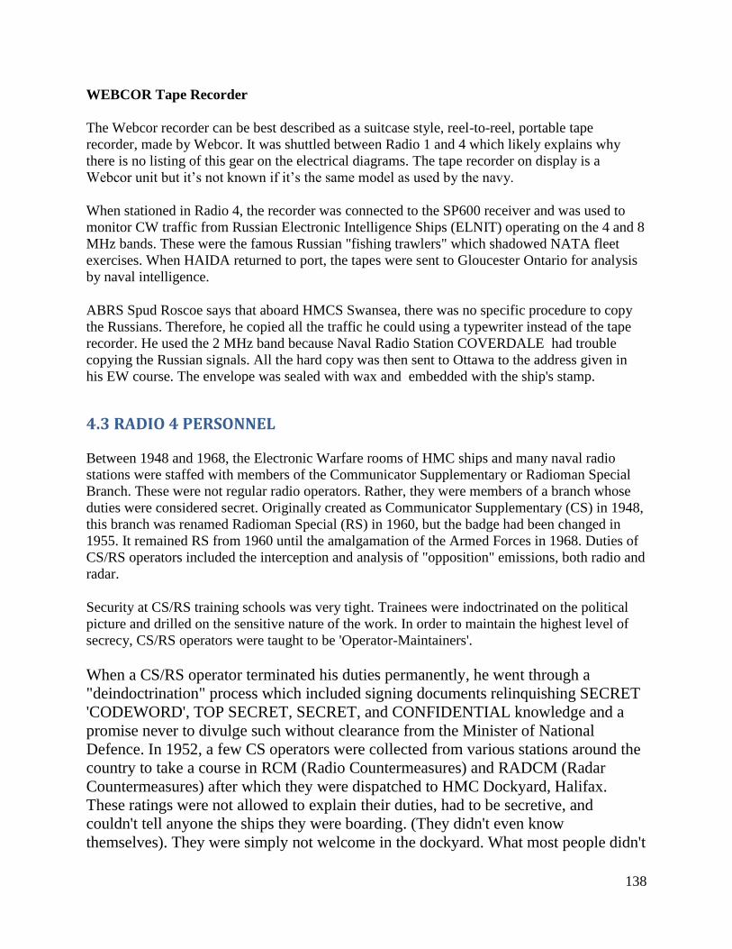
138
WEBCOR Tape Recorder
The Webcor recorder can be best described as a suitcase style, reel-to-reel, portable tape
recorder, made by Webcor. It was shuttled between Radio 1 and 4 which likely explains why
there is no listing of this gear on the electrical diagrams. The tape recorder on display is a
Webcor unit but it’s not known if it’s the same model as used by the navy.
When stationed in Radio 4, the recorder was connected to the SP600 receiver and was used to
monitor CW traffic from Russian Electronic Intelligence Ships (ELNIT) operating on the 4 and 8
MHz bands. These were the famous Russian "fishing trawlers" which shadowed NATA fleet
exercises. When HAIDA returned to port, the tapes were sent to Gloucester Ontario for analysis
by naval intelligence.
ABRS Spud Roscoe says that aboard HMCS Swansea, there was no specific procedure to copy
the Russians. Therefore, he copied all the traffic he could using a typewriter instead of the tape
recorder. He used the 2 MHz band because Naval Radio Station COVERDALE had trouble
copying the Russian signals. All the hard copy was then sent to Ottawa to the address given in
his EW course. The envelope was sealed with wax and embedded with the ship's stamp.
4.3 RADIO 4 PERSONNEL
Between 1948 and 1968, the Electronic Warfare rooms of HMC ships and many naval radio
stations were staffed with members of the Communicator Supplementary or Radioman Special
Branch. These were not regular radio operators. Rather, they were members of a branch whose
duties were considered secret. Originally created as Communicator Supplementary (CS) in 1948,
this branch was renamed Radioman Special (RS) in 1960, but the badge had been changed in
1955. It remained RS from 1960 until the amalgamation of the Armed Forces in 1968. Duties of
CS/RS operators included the interception and analysis of "opposition" emissions, both radio and
radar.
Security at CS/RS training schools was very tight. Trainees were indoctrinated on the political
picture and drilled on the sensitive nature of the work. In order to maintain the highest level of
secrecy, CS/RS operators were taught to be 'Operator-Maintainers'.
When a CS/RS operator terminated his duties permanently, he went through a
"deindoctrination" process which included signing documents relinquishing SECRET
'CODEWORD', TOP SECRET, SECRET, and CONFIDENTIAL knowledge and a
promise never to divulge such without clearance from the Minister of National
Defence. In 1952, a few CS operators were collected from various stations around the
country to take a course in RCM (Radio Countermeasures) and RADCM (Radar
Countermeasures) after which they were dispatched to HMC Dockyard, Halifax.
These ratings were not allowed to explain their duties, had to be secretive, and
couldn't tell anyone the ships they were boarding. (They didn't even know
themselves). They were simply not welcome in the dockyard. What most people didn't
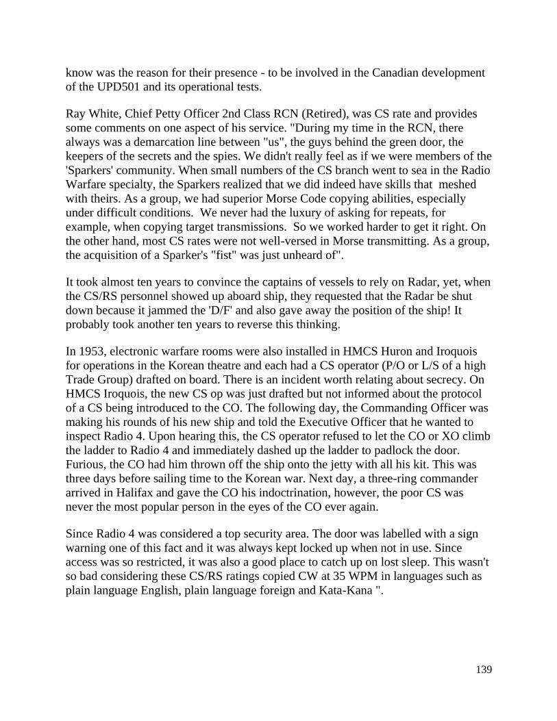
139
know was the reason for their presence - to be involved in the Canadian development
of the UPD501 and its operational tests.
Ray White, Chief Petty Officer 2nd Class RCN (Retired), was CS rate and provides
some comments on one aspect of his service. "During my time in the RCN, there
always was a demarcation line between "us", the guys behind the green door, the
keepers of the secrets and the spies. We didn't really feel as if we were members of the
'Sparkers' community. When small numbers of the CS branch went to sea in the Radio
Warfare specialty, the Sparkers realized that we did indeed have skills that meshed
with theirs. As a group, we had superior Morse Code copying abilities, especially
under difficult conditions. We never had the luxury of asking for repeats, for
example, when copying target transmissions. So we worked harder to get it right. On
the other hand, most CS rates were not well-versed in Morse transmitting. As a group,
the acquisition of a Sparker's "fist" was just unheard of".
It took almost ten years to convince the captains of vessels to rely on Radar, yet, when
the CS/RS personnel showed up aboard ship, they requested that the Radar be shut
down because it jammed the 'D/F' and also gave away the position of the ship! It
probably took another ten years to reverse this thinking.
In 1953, electronic warfare rooms were also installed in HMCS Huron and Iroquois
for operations in the Korean theatre and each had a CS operator (P/O or L/S of a high
Trade Group) drafted on board. There is an incident worth relating about secrecy. On
HMCS Iroquois, the new CS op was just drafted but not informed about the protocol
of a CS being introduced to the CO. The following day, the Commanding Officer was
making his rounds of his new ship and told the Executive Officer that he wanted to
inspect Radio 4. Upon hearing this, the CS operator refused to let the CO or XO climb
the ladder to Radio 4 and immediately dashed up the ladder to padlock the door.
Furious, the CO had him thrown off the ship onto the jetty with all his kit. This was
three days before sailing time to the Korean war. Next day, a three-ring commander
arrived in Halifax and gave the CO his indoctrination, however, the poor CS was
never the most popular person in the eyes of the CO ever again.
Since Radio 4 was considered a top security area. The door was labelled with a sign
warning one of this fact and it was always kept locked up when not in use. Since
access was so restricted, it was also a good place to catch up on lost sleep. This wasn't
so bad considering these CS/RS ratings copied CW at 35 WPM in languages such as
plain language English, plain language foreign and Kata-Kana ".
140
ABRS Spud Roscoe copies a message
from the SP600 receiver in the Radio 4
aboard HMCS SWANSEA in January
1961. Note the chain which holds down
the typewriter in case of heavy seas.
Pictures such as this were forbidden by
the RCN. (Photo courtesy Spud Roscoe)
4.4 MISCELLANEOUS EQUIPMENT - September 1955
MODEL REF NO. SERIAL NUMBER
SRE RCA Model 456 (need photo) ?
Two Whip Antennas 35 foot 3BA/16 3S1/347 n/a
Two TDQ/RCK Dipoles CLS 66059 n/a
Two TDZ/RDZ Dipoles General Electric n/a
5.0 ELECTRONIC NAVIGATION
5,1 GEE
An equipment manifest dated January 14, 1944 indicates that the GEE MKII navigation system
was installed using the QH3 Receiver. GEE transmitters were only situated in the UK, so the
system was only useable in the waters around the UK. The system had a useable range of around
350 nm. Since HAIDA was assigned to the 10th
Destroyer flotilla based in Plymouth England,
GEE would have been adequate for the role that she played in patrolling the English Channel
before and after D-Day. GEE equipment would have likely been removed by war’s end as it
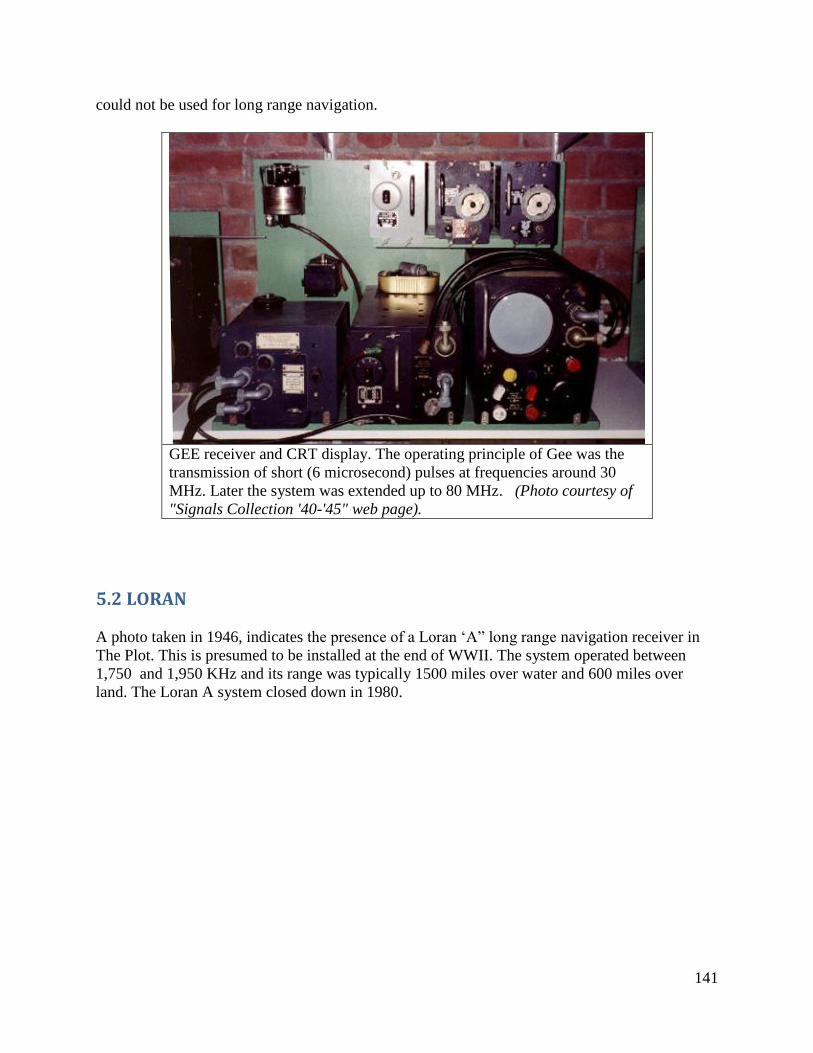
141
could not be used for long range navigation.
GEE receiver and CRT display. The operating principle of Gee was the
transmission of short (6 microsecond) pulses at frequencies around 30
MHz. Later the system was extended up to 80 MHz. (Photo courtesy of
"Signals Collection '40-'45" web page).
5.2 LORAN
A photo taken in 1946, indicates the presence of a Loran ‘A” long range navigation receiver in
The Plot. This is presumed to be installed at the end of WWII. The system operated between
1,750 and 1,950 KHz and its range was typically 1500 miles over water and 600 miles over
land. The Loran A system closed down in 1980.
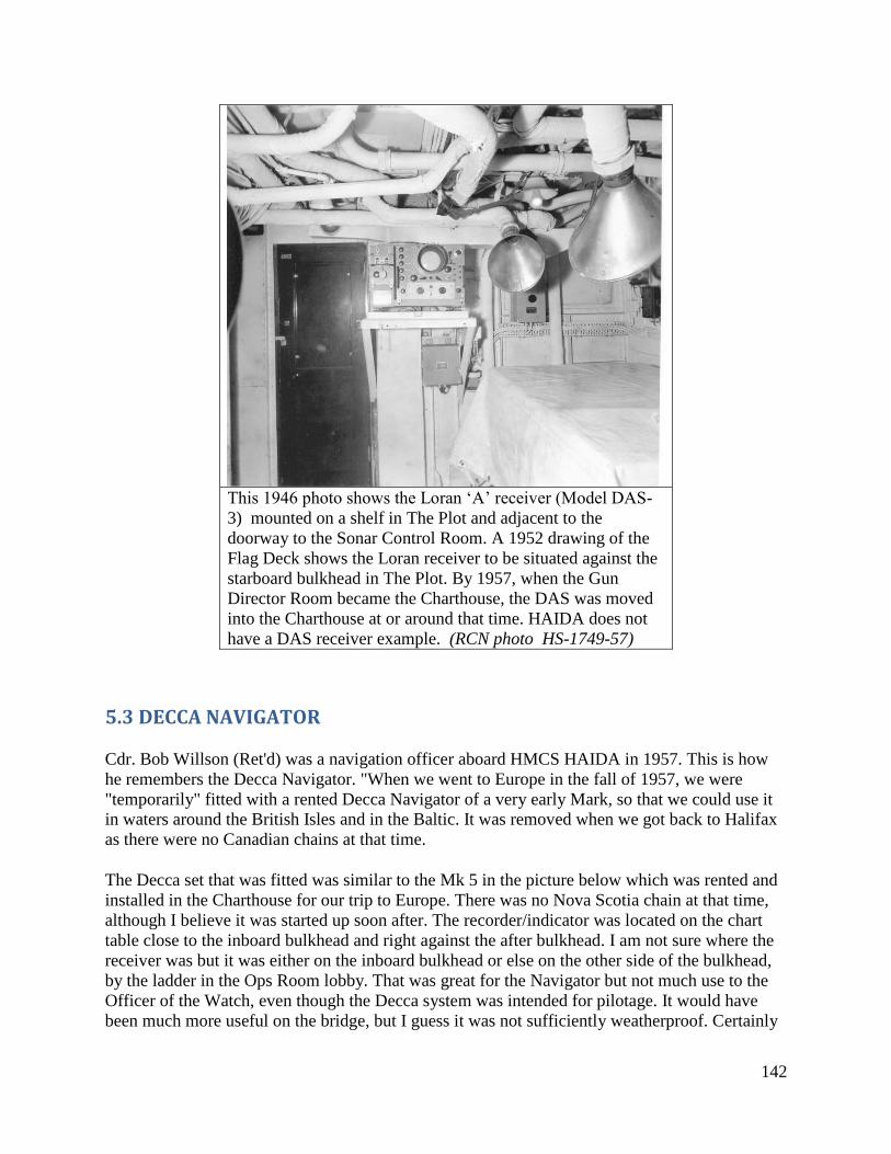
142
This 1946 photo shows the Loran ‘A’ receiver (Model DAS-
3) mounted on a shelf in The Plot and adjacent to the
doorway to the Sonar Control Room. A 1952 drawing of the
Flag Deck shows the Loran receiver to be situated against the
starboard bulkhead in The Plot. By 1957, when the Gun
Director Room became the Charthouse, the DAS was moved
into the Charthouse at or around that time. HAIDA does not
have a DAS receiver example. (RCN photo HS-1749-57)
5.3 DECCA NAVIGATOR
Cdr. Bob Willson (Ret'd) was a navigation officer aboard HMCS HAIDA in 1957. This is how
he remembers the Decca Navigator. "When we went to Europe in the fall of 1957, we were
"temporarily" fitted with a rented Decca Navigator of a very early Mark, so that we could use it
in waters around the British Isles and in the Baltic. It was removed when we got back to Halifax
as there were no Canadian chains at that time.
The Decca set that was fitted was similar to the Mk 5 in the picture below which was rented and
installed in the Charthouse for our trip to Europe. There was no Nova Scotia chain at that time,
although I believe it was started up soon after. The recorder/indicator was located on the chart
table close to the inboard bulkhead and right against the after bulkhead. I am not sure where the
receiver was but it was either on the inboard bulkhead or else on the other side of the bulkhead,
by the ladder in the Ops Room lobby. That was great for the Navigator but not much use to the
Officer of the Watch, even though the Decca system was intended for pilotage. It would have
been much more useful on the bridge, but I guess it was not sufficiently weatherproof. Certainly
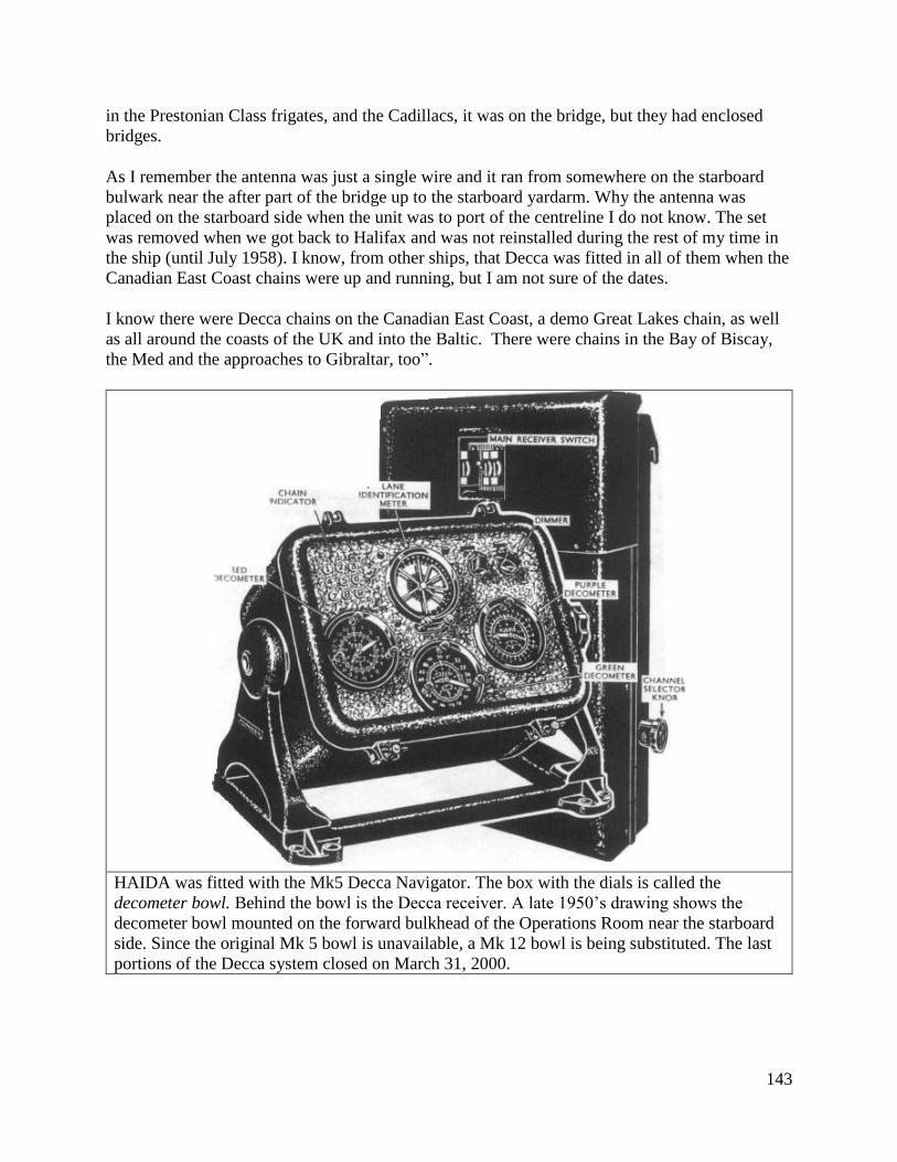
143
in the Prestonian Class frigates, and the Cadillacs, it was on the bridge, but they had enclosed
bridges.
As I remember the antenna was just a single wire and it ran from somewhere on the starboard
bulwark near the after part of the bridge up to the starboard yardarm. Why the antenna was
placed on the starboard side when the unit was to port of the centreline I do not know. The set
was removed when we got back to Halifax and was not reinstalled during the rest of my time in
the ship (until July 1958). I know, from other ships, that Decca was fitted in all of them when the
Canadian East Coast chains were up and running, but I am not sure of the dates.
I know there were Decca chains on the Canadian East Coast, a demo Great Lakes chain, as well
as all around the coasts of the UK and into the Baltic. There were chains in the Bay of Biscay,
the Med and the approaches to Gibraltar, too”.
HAIDA was fitted with the Mk5 Decca Navigator. The box with the dials is called the
decometer bowl. Behind the bowl is the Decca receiver. A late 1950’s drawing shows the
decometer bowl mounted on the forward bulkhead of the Operations Room near the starboard
side. Since the original Mk 5 bowl is unavailable, a Mk 12 bowl is being substituted. The last
portions of the Decca system closed on March 31, 2000.
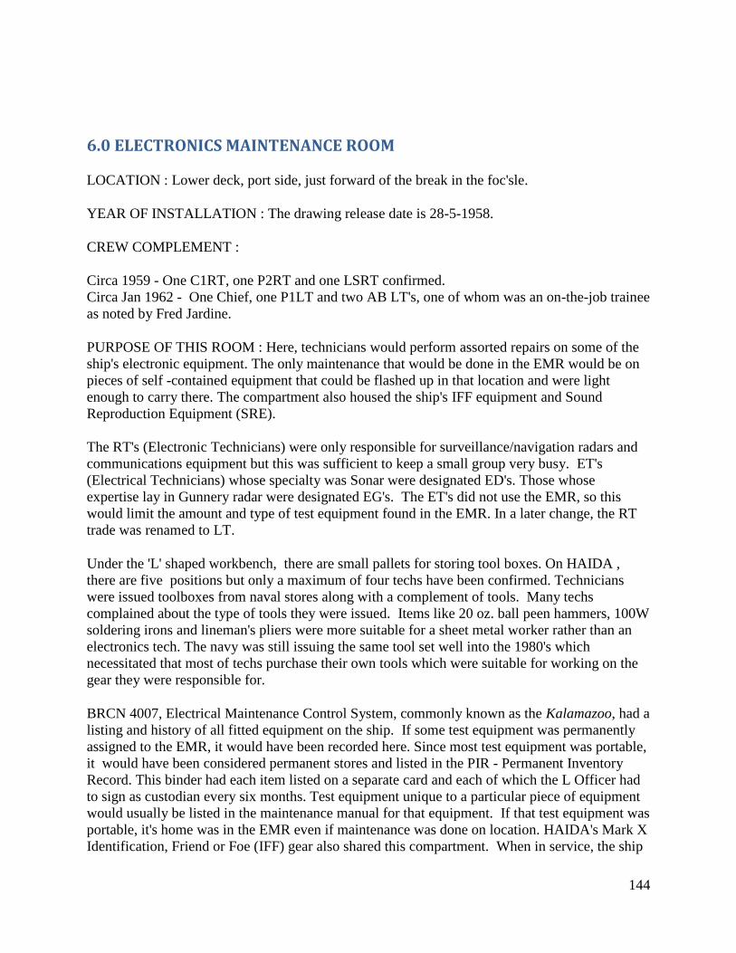
144
6.0 ELECTRONICS MAINTENANCE ROOM
LOCATION : Lower deck, port side, just forward of the break in the foc'sle.
YEAR OF INSTALLATION : The drawing release date is 28-5-1958.
CREW COMPLEMENT :
Circa 1959 - One C1RT, one P2RT and one LSRT confirmed.
Circa Jan 1962 - One Chief, one P1LT and two AB LT's, one of whom was an on-the-job trainee
as noted by Fred Jardine.
PURPOSE OF THIS ROOM : Here, technicians would perform assorted repairs on some of the
ship's electronic equipment. The only maintenance that would be done in the EMR would be on
pieces of self -contained equipment that could be flashed up in that location and were light
enough to carry there. The compartment also housed the ship's IFF equipment and Sound
Reproduction Equipment (SRE).
The RT's (Electronic Technicians) were only responsible for surveillance/navigation radars and
communications equipment but this was sufficient to keep a small group very busy. ET's
(Electrical Technicians) whose specialty was Sonar were designated ED's. Those whose
expertise lay in Gunnery radar were designated EG's. The ET's did not use the EMR, so this
would limit the amount and type of test equipment found in the EMR. In a later change, the RT
trade was renamed to LT.
Under the 'L' shaped workbench, there are small pallets for storing tool boxes. On HAIDA ,
there are five positions but only a maximum of four techs have been confirmed. Technicians
were issued toolboxes from naval stores along with a complement of tools. Many techs
complained about the type of tools they were issued. Items like 20 oz. ball peen hammers, 100W
soldering irons and lineman's pliers were more suitable for a sheet metal worker rather than an
electronics tech. The navy was still issuing the same tool set well into the 1980's which
necessitated that most of techs purchase their own tools which were suitable for working on the
gear they were responsible for.
BRCN 4007, Electrical Maintenance Control System, commonly known as the Kalamazoo, had a
listing and history of all fitted equipment on the ship. If some test equipment was permanently
assigned to the EMR, it would have been recorded here. Since most test equipment was portable,
it would have been considered permanent stores and listed in the PIR - Permanent Inventory
Record. This binder had each item listed on a separate card and each of which the L Officer had
to sign as custodian every six months. Test equipment unique to a particular piece of equipment
would usually be listed in the maintenance manual for that equipment. If that test equipment was
portable, it's home was in the EMR even if maintenance was done on location. HAIDA's Mark X
Identification, Friend or Foe (IFF) gear also shared this compartment. When in service, the ship
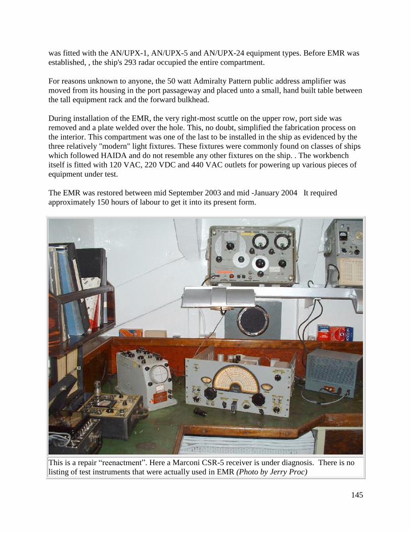
145
was fitted with the AN/UPX-1, AN/UPX-5 and AN/UPX-24 equipment types. Before EMR was
established, , the ship's 293 radar occupied the entire compartment.
For reasons unknown to anyone, the 50 watt Admiralty Pattern public address amplifier was
moved from its housing in the port passageway and placed unto a small, hand built table between
the tall equipment rack and the forward bulkhead.
During installation of the EMR, the very right-most scuttle on the upper row, port side was
removed and a plate welded over the hole. This, no doubt, simplified the fabrication process on
the interior. This compartment was one of the last to be installed in the ship as evidenced by the
three relatively "modern" light fixtures. These fixtures were commonly found on classes of ships
which followed HAIDA and do not resemble any other fixtures on the ship. . The workbench
itself is fitted with 120 VAC, 220 VDC and 440 VAC outlets for powering up various pieces of
equipment under test.
The EMR was restored between mid September 2003 and mid -January 2004 It required
approximately 150 hours of labour to get it into its present form.
This is a repair “reenactment”. Here a Marconi CSR-5 receiver is under diagnosis. There is no
listing of test instruments that were actually used in EMR (Photo by Jerry Proc)
146
6.1 PUBLIC ADDRESS SYSTEMS
HAIDA has four separate Public Address systems fitted. At the heart of each system was a 50
watt, marine type amplifier designated as AP 12522. The AID system incorporated two of the
amplifiers. One was the active unit while the other remained in standby. Announcements of a
general nature would be made on the AID system.
Another amplifier was used for the Armament Broadcast System (ABS). It provided service for
the crew manning the weapons and the Transmitting Station. The Sound Reproduction
Equipment (SRE) function had its own amplifier. Lastly, there was one system dedicated to
personnel manning the SONAR gear.
The SRE amplifier was positioned on a small bench in the Electronics Maintenance Room.
Located on a nearby rack was a Marconi Model 456 entertainment receiver, the output of which
could be piped to the amplifier input. As an alternate input, the Hammarlund SP600 receiver in
Radio 4 could have been used as an entertainment source or the reel-to-reel tape recorder which
was resident in the same space.
When in harbour, the PA system was operated from the brow to disseminate information and
orders. At sea, it could originate from several locations. Most common locations were the bridge
(aft quarter position) and the wheelhouse.
Dennis Stapelton served in the RCN during the early 1950's. He provides some examples of
messages which were announced on the PA system. "The ships PA system was used for wakey
wakey, advising certain personnel to report to offices, announcing scheduled events throughout
the day such as “up spirits” (at sea), and out lights in the evening. The captain would use it for
advisory warnings when going ashore in certain ports to behave properly.
When entering and leaving harbour, a pipe would be made to “assume damage control state (A
or B can’t remember), close all X and Y hatches, special sea duty men close up” -- the chance of
collision was greater when maneuvering in a harbour.
One pipe I shall always remember was when I first joined HMCS Magnificent. We were fueling
at the jetty on the north side of Halifax harbour and taking on Avgas, a very volatile fuel that
emitted dangerous fumes during the operation. The pipe came forbidding the making or
breaking of all electrical contacts throughout the ship. This was kind of a wake up call for me as
very junior member of the crew. That indicated the precautions a warship had to observe to avoid
disaster".
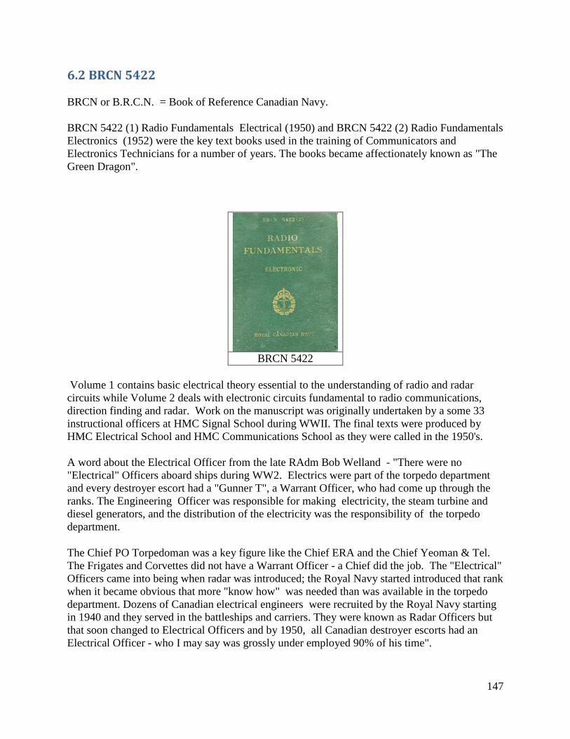
147
6.2 BRCN 5422
BRCN or B.R.C.N. = Book of Reference Canadian Navy.
BRCN 5422 (1) Radio Fundamentals Electrical (1950) and BRCN 5422 (2) Radio Fundamentals
Electronics (1952) were the key text books used in the training of Communicators and
Electronics Technicians for a number of years. The books became affectionately known as "The
Green Dragon".
BRCN 5422
Volume 1 contains basic electrical theory essential to the understanding of radio and radar
circuits while Volume 2 deals with electronic circuits fundamental to radio communications,
direction finding and radar. Work on the manuscript was originally undertaken by a some 33
instructional officers at HMC Signal School during WWII. The final texts were produced by
HMC Electrical School and HMC Communications School as they were called in the 1950's.
A word about the Electrical Officer from the late RAdm Bob Welland - "There were no
"Electrical" Officers aboard ships during WW2. Electrics were part of the torpedo department
and every destroyer escort had a "Gunner T", a Warrant Officer, who had come up through the
ranks. The Engineering Officer was responsible for making electricity, the steam turbine and
diesel generators, and the distribution of the electricity was the responsibility of the torpedo
department.
The Chief PO Torpedoman was a key figure like the Chief ERA and the Chief Yeoman & Tel.
The Frigates and Corvettes did not have a Warrant Officer - a Chief did the job. The "Electrical"
Officers came into being when radar was introduced; the Royal Navy started introduced that rank
when it became obvious that more "know how" was needed than was available in the torpedo
department. Dozens of Canadian electrical engineers were recruited by the Royal Navy starting
in 1940 and they served in the battleships and carriers. They were known as Radar Officers but
that soon changed to Electrical Officers and by 1950, all Canadian destroyer escorts had an
Electrical Officer - who I may say was grossly under employed 90% of his time".
148
All the engineering drawings for the ship were located in the Engineering Officer's cabin, an area
which doubled as an office and living quarters for the Engineering Officer. He was responsible
for all things electrical and electronic and thus had custody of the electrical drawings. The
electronic/electrical drawings were not stored in the Electrical Officer's cabin, but could have
been held in the Electrical Workshop, with electronic (radar, comm, etc) drawings held in the
Electronics Maintenance Room.
6.3 CANAVMOD
Jim Dean, VE3IQ, explains the term CANAVMOD (Canadian Naval Modification). "It is the
process whereby modifications to existing equipment are engineered, authorized and installed. It
is configuration management for individual equipments".
6.4 ‘AN' Army-Navy Equipment Code Designators
On the front of many pieces of military electronic equipment is a name plate displaying a group
of letters and numbers which identify the gear. When equipment is procured for the military,
equipment model numbers are assigned in accordance with the Joint Electronics Type
Designation System. The first two letters are AN. This is the service indicator meaning Army-
Navy but does include Air Force. AN is followed by a slant and three identifying letters. The
AN system dates back to around 1945.
FIRST LETTER - Type of installation.
SECOND LETTER - Type of equipment.
THIRD LETTER - Purpose of equipment.
NUMERICS - Denotes the specific model of equipment.
Example: AN/UPD501 means:
AN is Army-Navy
U is Utility
P is Radar
501 – Anything beginning with 5xx is a Canadian series, so 501 is the first device in this series.
Foreign-designed equipment, when built in Canada, was assigned a 500 series number as well as
equipment designed and built in Canada. For instance, the AN/ARC 52 UHF set when built in
Canada became the AN/ARC 552.
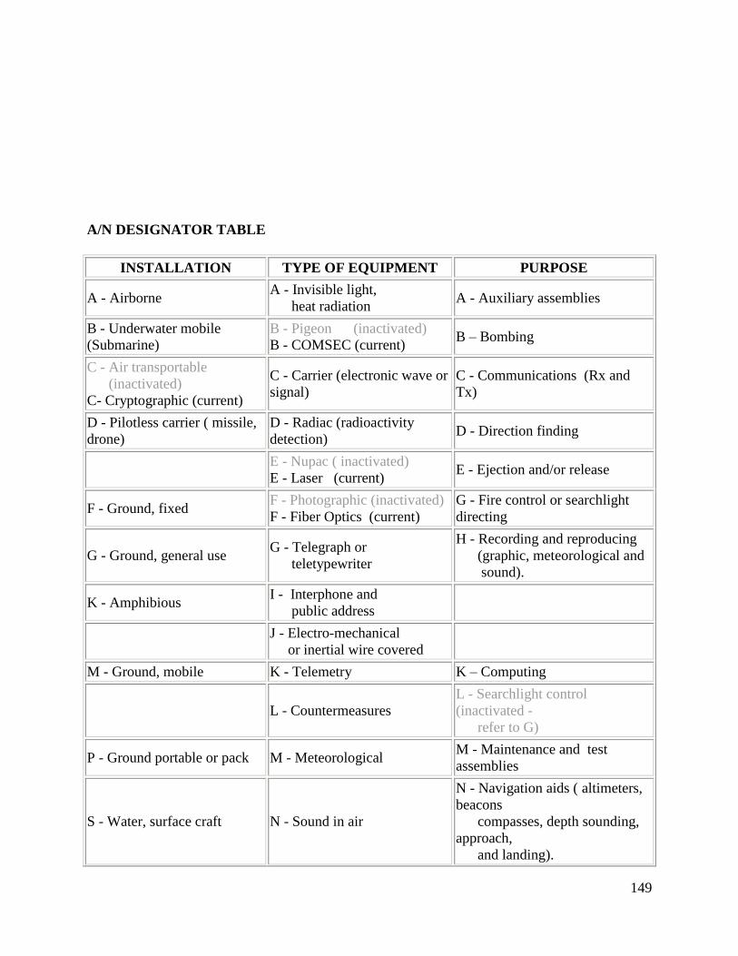
149
A/N DESIGNATOR TABLE
INSTALLATION TYPE OF EQUIPMENT PURPOSE
A - Airborne A - Invisible light,
heat radiation A - Auxiliary assemblies
B - Underwater mobile
(Submarine)
B - Pigeon (inactivated)
B - COMSEC (current) B – Bombing
C - Air transportable
(inactivated)
C- Cryptographic (current)
C - Carrier (electronic wave or
signal)
C - Communications (Rx and
Tx)
D - Pilotless carrier ( missile,
drone)
D - Radiac (radioactivity
detection) D - Direction finding
E - Nupac ( inactivated)
E - Laser (current) E - Ejection and/or release
F - Ground, fixed F - Photographic (inactivated)
F - Fiber Optics (current)
G - Fire control or searchlight
directing
G - Ground, general use G - Telegraph or
teletypewriter
H - Recording and reproducing
(graphic, meteorological and
sound).
K - Amphibious I - Interphone and
public address
J - Electro-mechanical
or inertial wire covered
M - Ground, mobile K - Telemetry K – Computing
L - Countermeasures
L - Searchlight control
(inactivated -
refer to G)
P - Ground portable or pack M - Meteorological M - Maintenance and test
assemblies
S - Water, surface craft N - Sound in air
N - Navigation aids ( altimeters,
beacons
compasses, depth sounding,
approach,
and landing).
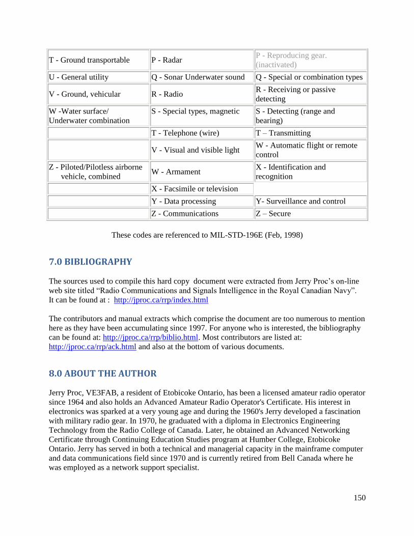
150
T - Ground transportable P - Radar P - Reproducing gear.
(inactivated)
U - General utility Q - Sonar Underwater sound Q - Special or combination types
V - Ground, vehicular R - Radio R - Receiving or passive
detecting
W -Water surface/
Underwater combination
S - Special types, magnetic S - Detecting (range and
bearing)
T - Telephone (wire) T – Transmitting
V - Visual and visible light
W - Automatic flight or remote
control
Z - Piloted/Pilotless airborne
vehicle, combined W - Armament
X - Identification and
recognition
X - Facsimile or television
Y - Data processing Y- Surveillance and control
Z - Communications Z – Secure
These codes are referenced to MIL-STD-196E (Feb, 1998)
7.0 BIBLIOGRAPHY
The sources used to compile this hard copy document were extracted from Jerry Proc’s on-line
web site titled “Radio Communications and Signals Intelligence in the Royal Canadian Navy”.
It can be found at : http://jproc.ca/rrp/index.html
The contributors and manual extracts which comprise the document are too numerous to mention
here as they have been accumulating since 1997. For anyone who is interested, the bibliography
can be found at: http://jproc.ca/rrp/biblio.html. Most contributors are listed at:
http://jproc.ca/rrp/ack.html and also at the bottom of various documents.
8.0 ABOUT THE AUTHOR
Jerry Proc, VE3FAB, a resident of Etobicoke Ontario, has been a licensed amateur radio operator
since 1964 and also holds an Advanced Amateur Radio Operator's Certificate. His interest in
electronics was sparked at a very young age and during the 1960's Jerry developed a fascination
with military radio gear. In 1970, he graduated with a diploma in Electronics Engineering
Technology from the Radio College of Canada. Later, he obtained an Advanced Networking
Certificate through Continuing Education Studies program at Humber College, Etobicoke
Ontario. Jerry has served in both a technical and managerial capacity in the mainframe computer
and data communications field since 1970 and is currently retired from Bell Canada where he
was employed as a network support specialist.
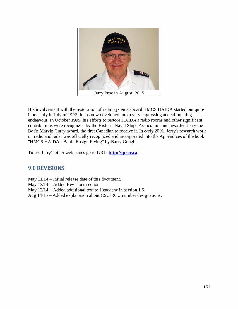
151
Jerry Proc in August, 2015
His involvement with the restoration of radio systems aboard HMCS HAIDA started out quite
innocently in July of 1992. It has now developed into a very engrossing and stimulating
endeavour. In October 1999, his efforts to restore HAIDA's radio rooms and other significant
contributions were recognized by the Historic Naval Ships Association and awarded Jerry the
Bos'n Marvin Curry award, the first Canadian to receive it. In early 2001, Jerry's research work
on radio and radar was officially recognized and incorporated into the Appendices of the book
"HMCS HAIDA - Battle Ensign Flying" by Barry Gough.
To see Jerry's other web pages go to URL: http://jproc.ca
9.0 REVISIONS
May 11/14 – Initial release date of this document.
May 13/14 – Added Revisions section.
May 13/14 – Added additional text to Headache in section 1.5.
Aug 14/15 – Added explanation about CSU/RCU number designations.


![DECCA DISCOGRAPHYimages.cch.kcl.ac.uk/charm/liv/pubs/DeccaH.pdf · [b] Symphony No.2 in C minor “Resurrection” [Licensed from Katholieke Radio Omroep in 1982] [b] (Sep82) D264D2,](https://img.pdfslide.us/doc/110x75/5f5cd8b9cd7b9e080f67b133/decca-b-symphony-no2-in-c-minor-aoeresurrectiona-licensed-from-katholieke.jpg)