Embed Size (px)
Citation preview

Revision: 4.0.0.3

SP420/SP420-F 4x4 Dual Band 802.11ac Wave 2 Outdoor Access Point User Manual
58-150005-IQN_V1.0 Page ii
TABLE OF CONTENTS Introduction ......................................................................................................................................................... 1 Chapter 1.
Product Description ....................................................................................................................................................................................... 1 1.1. Features ............................................................................................................................................................................................................... 1 1.2.
Hardware Components ...................................................................................................................................... 2 Chapter 2. Package Contents ........................................................................................................................................................................................... 2 2.1. Installation Requirements ............................................................................................................................................................................ 2 2.2. Physical Ports .................................................................................................................................................................................................... 2 2.3. LED Indicator ..................................................................................................................................................................................................... 3 2.4.
Hardware Installation ......................................................................................................................................... 4 Chapter 3. Mounting the Access Point on the Pole................................................................................................................................................. 4 3.1. Two-dimensional Mounting Kit (Optional accessory SP-MKM5) ................................................................................................ 4 3.2.
Pole-Mount ............................................................................................................................................................................................. 4 3.2.1. Wall-Mount ............................................................................................................................................................................................. 5 3.2.2.
Anti-theft Steel Rope (Optional accessory_SP-CBM5) ..................................................................................................................... 5 3.3. Grounding Connection & Protect from Lightning ............................................................................................................................. 6 3.4. Safety Notice ..................................................................................................................................................................................................... 6 3.5. Installing a Waterproof Cable Gland for Ethernet Port .................................................................................................................... 7 3.6. Installing a Waterproof Cable Gland for Fiber Port of SP420-F (Optional accessory_ SP-WP-CM28SFP) ................... 7 3.7. Powering the Access Point .......................................................................................................................................................................... 7 3.8.
The HTTP Interface ............................................................................................................................................. 8 Chapter 4. Login to the HTTP Interface ........................................................................................................................................................................ 8 4.1. Thin AP Mode ................................................................................................................................................................................................... 8 4.2.
Access point Configuration ............................................................................................................................................................... 8 4.2.1. Status ......................................................................................................................................................................................................... 9 4.2.2.
4.2.2.1. Overview ......................................................................................................................................................................................... 9 4.2.2.2. General ......................................................................................................................................................................................... 10 4.2.2.3. System Log ................................................................................................................................................................................. 11
System .................................................................................................................................................................................................... 11 4.2.3.4.2.3.1. AP Mode ...................................................................................................................................................................................... 11 4.2.3.2. Reboot .......................................................................................................................................................................................... 11
Fat AP Mode ................................................................................................................................................................................................... 11 4.3. Status ...................................................................................................................................................................................................... 12 4.3.1.
4.3.1.1. Overview ...................................................................................................................................................................................... 12 4.3.1.2. Firewall ......................................................................................................................................................................................... 13 4.3.1.3. Routes........................................................................................................................................................................................... 13 4.3.1.4. System Log ................................................................................................................................................................................. 13
System .................................................................................................................................................................................................... 15 4.3.2.4.3.2.1. System .......................................................................................................................................................................................... 15 4.3.2.2. Administration........................................................................................................................................................................... 15 4.3.2.3. Scheduled Tasks ....................................................................................................................................................................... 16 4.3.2.4. Backup / Flash Firmware ....................................................................................................................................................... 16
Network ................................................................................................................................................................................................. 17 4.3.3.4.3.3.1. Interfaces ..................................................................................................................................................................................... 17 4.3.3.2. Wifi ................................................................................................................................................................................................. 43

SP420/SP420-F 4x4 Dual Band 802.11ac Wave 2 Outdoor Access Point User Manual
58-150005-IQN_V1.0 Page iii
4.3.3.4. Static Routes .............................................................................................................................................................................. 58 4.3.3.5. Diagnostics ................................................................................................................................................................................. 59 4.3.3.6. Firewall ......................................................................................................................................................................................... 61 4.3.3.7. Bluetooth ..................................................................................................................................................................................... 64 4.3.3.8. Externalvlan ................................................................................................................................................................................ 64 Technical Specifications ................................................................................................................................... 65 Chapter 5.
Appendix ............................................................................................................................................................ 67 Chapter 6. Warranty .......................................................................................................................................................................................................... 67 6.1.
General Warranty ............................................................................................................................................................................... 67 6.1.1. Warranty Conditions ......................................................................................................................................................................... 67 6.1.2. Disclaimer .............................................................................................................................................................................................. 67 6.1.3.
Compliance Information ............................................................................................................................................................................ 68 6.2. RF Exposure Warning ....................................................................................................................................................................... 68 6.2.1. CE Marking ........................................................................................................................................................................................... 68 6.2.2. RoHS/WEEE Compliance Statement ........................................................................................................................................... 68 6.2.3.
Declaration of Conformity ........................................................................................................................................................................ 68 6.3. Optional Accessories................................................................................................................................................................................... 69 6.4. Contact Information .................................................................................................................................................................................... 69 6.5.

SP420/SP420-F 4x4 Dual Band 802.11ac Wave 2 Outdoor Access Point User Manual
58-150005-IQN_V1.0 Page 1
INTRODUCTION Chapter 1.This guide is intended for network administrators and other IT networking professionals responsible for installing and managing the SP420 Series using the HTTP interface. The SP420 series will simply be referred to as the AP within this guide. This guide is written in a way that assumes that users already have the experience and knowledge of Ethernet and modern networking principles for LANs (Local Area Networks) and WLANs (Wireless LANs).
Product Description 1.1.The SP420 series are dual-band 4x4 Wave 2 outdoor APs (Access Points) that supports the IEEE 802.11ac standard and can provided wireless data rates up to 2.3 Gbps and optimizing the 2.4 GHz and 5 GHz frequency bands.
Standards IEEE 802.11a/b/g/n/ac
Radio Chains 2.4 GHz: 4x4:4 5GHz: 4x4:4
Antenna SP420 SP420-F
2.4 GHz: 5dBi (Embedded) 5GHz: 5dBi (Embedded)
2.4 GHz: 5dBi (Embedded) 5GHz: 5dBi (Embedded)
Antenna Type 2.4/5GHz: Omni antenna
Interface 2 x 1GbE RJ45 port 1 × Ground terminal
1 x 1GbE RJ45 port 1 × 1GbE SFP 1 × Ground terminal
Features 1.2.MU-MIMO Technology - Supports four spatial streams, to maximize throughput for high-density applications. PoE Out - Powering a device such as an IP camera or a VoIP product for fast deployment. Location Service - Integrated Bluetooth Low Energy (BLE) 4.1 radio to enable location tracking and wayfinding. Wi-Fi SON - Accelerates the connection speed between devices, providing users with quick installation and easy deployment capabilities Robust Product Design - Encased with IP67-rated and scale-level 14 windproof robust design that can withstand harsh environments. Fiber Connector (SP420-F) - Adopts fiber cable for farther deployment and cost-effective applications.

SP420/SP420-F 4x4 Dual Band 802.11ac Wave 2 Outdoor Access Point User Manual
58-150005-IQN_V1.0 Page 2
HARDWARE COMPONENTS Chapter 2. Package Contents 2.1.
One outdoor access point One clamp One waterproof cable gland
One ground wire One mounting bracket + Four screws
One waterproof cable gland for
fiber port
Note: SP420 provides two waterproof cable glands, and SP420-F provides one waterproof cable gland and one waterproof cable gland for fiber port.
Installation Requirements 2.2.TERMS OF USE: All Ethernet cabling runs must use CAT5e, 24AWG (or above) Shielded Twisted Pair (STP) cabling. It is the professional installer’s responsibility to follow local country regulations, including operation within legal frequency channels, output power, indoor cabling requirements, and Dynamic Frequency Selection (DFS) requirements.
Note: Be sure that grounding is available and that it must comply with local and national electrical codes. For additional lightning protection, use lightning rods and lightning arrestors.
Physical Ports 2.3.The following physical ports are available on the SP420 /SP420-F.
SP420 SP420-F Fiber Port - 1 WAN/PoE In Port 1 1 LAN Port 1 - Grounding 1 1

SP420/SP420-F 4x4 Dual Band 802.11ac Wave 2 Outdoor Access Point User Manual
58-150005-IQN_V1.0 Page 3
Port Description
Fiber Port Fiber port is used in a point-to-point fiber run to an outdoor 802.11n wireless access point.
WAN/PoE In Port
The WAN/PoE In port operates at 10/100/1000 Mbps at supports an RJ45 connection. Supporting PoE In, the AP can receive power through the WAN port from PSE (Power Sourcing Equipment), rendering the need for a power supply into the power port unnecessary.
LAN Port
The LAN/PoE Out port operates at 10/100/1000 Mbps at supports an RJ45 connector. Supporting PoE Out, the LAN port can supply PoE power to PDs (Powered Devices) plugged into the LAN port. Up to 11.5 Watts output power can be supplied.
Grounding Access point that can't find its way to local earth ground will transfer to the interior equipment over the communication and power cable.
LED Indicator 2.4.Color Indicator Behavior Description
Red
PWR Off Power / system off
Steady Power / system on
WLAN
Off 2G and 5G WLAN interface disabled
Steady 2G or 5G WLAN interface enabled
Flashing Sending / receiving data
WAN
Off No internet connection detected
Steady Internet connection detected
Flashing Sending / receiving data

SP420/SP420-F 4x4 Dual Band 802.11ac Wave 2 Outdoor Access Point User Manual
58-150005-IQN_V1.0 Page 4
HARDWARE INSTALLATION Chapter 3. Mounting the Access Point on the Pole 3.1.
Place the mounting bracket to the device using four screws (included in the packaging). Securely tighten the screws.
Attach the clamp to encircle pole and the mounting bracket. Securely tighten the clamp.
Note: Avoid having obstacles or metal plates surround the access point.
Two-dimensional Mounting Kit (Optional accessory SP-3.2.
MKM5) Pole-Mount 3.2.1.
Attach the intermediate steel plate to the device using four M5 screws (included in the packaging). Securely tighten the screws.
Attach the two-dimensional mounting bracket to the intermediate steel plate using four M4 screws (included in the packaging). Securely tighten the screws.
Attach the pole-supported bracket and align the area where the flat head screws will be
attached. Insert two flat head screws into two-dimensional mounting bracket, and tighten them approximately.
Note: The pole-supported bracket can accommodate up to 6 cm (2.36”) in diameter.

SP420/SP420-F 4x4 Dual Band 802.11ac Wave 2 Outdoor Access Point User Manual
58-150005-IQN_V1.0 Page 5
Wall-Mount 3.2.2. Separate it into two parts: half-mounting
bracket and M-type bracket and unscrew four hex head machine bolts on the two-dimensional mounting bracket.
Attach the intermediate steel plate to the device using four M5 screws (included in the packaging). Securely tighten the screws.
Attach half-mounting bracket to the device with intermediate steel plate using four M4 screws (included in the packaging). Securely tighten the screws.
Attach M-type bracket to the device onto the wall, using four M5 screws + screw anchors (included in the packaging). Securely tighten the screws.
Attach half-mounting bracket to the M-type bracket, then screw four hex head machine bolts. Securely tighten the screws.
Anti-theft Steel Rope (Optional accessory_SP-CBM5) 3.3.
Insert three anti-theft screws (included in the packaging) to the device through the mounting bracket. Securely tighten these three screws. Attach the clamp to encircle pole and the mounting bracket. Securely tighten the clamp.
Firstly, encircle the Anti-theft steel rope as following left diagram, then encircle on the pole. Secondly, insert the last anti-theft screw (included in the packaging) to the device with anti-theft steel rope. Securely tighten the screw.
SP420/SP420-F 4x4 Dual Band 802.11ac Wave 2 Outdoor Access Point User Manual
58-150005-IQN_V1.0 Page 6
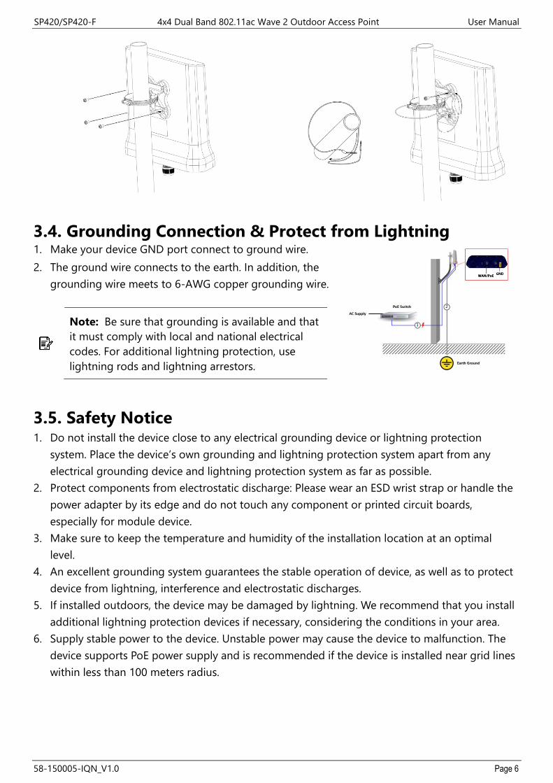
Grounding Connection & Protect from Lightning 3.4.1. Make your device GND port connect to ground wire. 2. The ground wire connects to the earth. In addition, the
grounding wire meets to 6-AWG copper grounding wire.
Note: Be sure that grounding is available and that it must comply with local and national electrical codes. For additional lightning protection, use lightning rods and lightning arrestors.
Safety Notice 3.5.1. Do not install the device close to any electrical grounding device or lightning protection
system. Place the device’s own grounding and lightning protection system apart from any electrical grounding device and lightning protection system as far as possible.
2. Protect components from electrostatic discharge: Please wear an ESD wrist strap or handle the power adapter by its edge and do not touch any component or printed circuit boards, especially for module device.
3. Make sure to keep the temperature and humidity of the installation location at an optimal level.
4. An excellent grounding system guarantees the stable operation of device, as well as to protect device from lightning, interference and electrostatic discharges.
5. If installed outdoors, the device may be damaged by lightning. We recommend that you install additional lightning protection devices if necessary, considering the conditions in your area.
6. Supply stable power to the device. Unstable power may cause the device to malfunction. The device supports PoE power supply and is recommended if the device is installed near grid lines within less than 100 meters radius.

SP420/SP420-F 4x4 Dual Band 802.11ac Wave 2 Outdoor Access Point User Manual
58-150005-IQN_V1.0 Page 7
Installing a Waterproof Cable Gland for Ethernet Port 3.6.(Optional accessory_ SP-WP-CM20) Dismantle all the components of waterproof cable gland, and
plug the cable through it. Thread and assemble one by one: (1) sealing nut (2) plastic ring (3) rubber (4) locking nut. Securely tighten all the components.
Installing a Waterproof Cable Gland for Fiber Port of 3.7.SP420-F (Optional accessory_ SP-WP-CM28SFP)
Dismantle all the components of waterproof cable gland, and plug the cable through it.
Assemble all the components together; securely tighten the main unit and the sealing nut.
Note: For SP420-F fiber port version, it is not available for PoE Out function.
Note: For SP420-F, it is recommended to purchase 1000BASE-SX SFP transceiver module, and fiber patch cord for fiber port connection.
Powering the Access Point 3.8.Connect the PoE cable into the WAN/PoE IN port of the device, then it will power on.
Warning: Do NOT attempt to connect any non-PoE devices to LAN port and make sure the input power should comply with PoE Out standard.
Note: Please wait for 5-10 seconds while powering on.
Note: For PoE Out applications, the LAN port provides DC 48V, Max. 208mA, and up to 10W power supply. The positive side of the 48V is connected to pin 4 and 5, the negative side is connected to pin 7 and 8.

SP420/SP420-F 4x4 Dual Band 802.11ac Wave 2 Outdoor Access Point User Manual
58-150005-IQN_V1.0 Page 8
THE HTTP INTERFACE Chapter 4.The AP can be configured through its supported software interface HTTP. The HTTP interface can be accessed using any standard web browsing software through any network. This chapter explains all the elements that are available on the HTTP interface of the AP.
Note: The default Username is root and Password is password.
Note: Click the icon to add a new entry. Click the icon to remove an entry.
Note: Click Reset button to return the parameters on the page to their previously saved state.
Note: Click Save button to accept and save the modifications made on the page.
Note: Click Save & Apply button to save and apply the modifications made on the page.
Login to the HTTP Interface 4.1. To access the HTTP interface on the AP, enter the IP address of the AP into the web browser’s
address bar and press the Enter key.
Enter the Username and Password in the respective textboxes and click the Login button. To return the information, displayed in the textboxes to the defaults, click the Reset button.
In a default access point configuration, the SP420 series default AP mode is TAP mode.
Thin AP Mode 4.2.The procedure for completing the access point’s essential configuration depends on whether you want it to be managed by wireless LAN controllers (WLC).
To configure the access point to be managed by the WLC, you must ensure that the APs will be able to locate and connect to the WLC when powered on. When connected to the network, each AP is assigned a valid IP address.
Access point Configuration 4.2.1.In a default access point configuration, the access point default AP mode is TAP mode, and obtains IP addresses from DHCP Option 43 protocol.
Note: In TAP mode, the AP must be able to go with Wireless LAN Controllers (WLCs) for bulk configuration and performing other commands of access points. Please refer to WLC QSG for settings first, then go back to finish the AP configuration. https://www.zcom.com.tw/index/downloads?keyword=&meterial_type=49
Step 1. Power on the access point. As the status of LED indicator from flashing change to steady red, the connection is successful.

SP420/SP420-F 4x4 Dual Band 802.11ac Wave 2 Outdoor Access Point User Manual
58-150005-IQN_V1.0 Page 9
Note: Please make sure DHCP server is enabled on the network once accomplished WLC settings. The access point must receive its IP address through DHCP server.
Note: Switching from DHCP to assign a static IP address or DNS and L2 discovery mode to the access point, please refer to the user manual for more information. https://www.zcom.com.tw/index/downloads?keyword=&meterial_type=25
If the access point cannot connect to the WLC by DHCP broadcast, please refer to the following optional settings.
Optional: Set up a static IP address
Note: The following procedure assumes that Windows 10 is the operating system. Procedures for other operating systems are similar.
Step 1. On your computer, configure your network adapter from the “Local Area Connection “settings as follows: ˙ StartControl PanelNetwork & InternetChange Adapter OptionsEthernet
Step 2. Edit the TCP/IPv4 address setting as follows: ˙ PropertiesInternet Protocol Version 4 (TCP/IPv4)
Step 3. Select “Use the following IP address” and make the following entries: ˙ IP address: 192.168.1.168 (or any available address in the 192.168.1.x network, except
192.168.1.1) ˙ Subnet mask: 255.255.255.0
Leave the “Default gateway” and “DNS server” fields empty.
Step 4. Click “OK” to save your changes. Login into the access point
Step 5. Launch a Web browser; type default URL https://192.168.1.1 to connect to the access point. When a security alert dialog box appears, click OK/Yes to proceed.
Step 6. When login page appears, enter the following: Username: root/Password: password
Step 7. Click login.
Customizing the Wireless Settings On the Web interface menu, Select StatusGeneral in the menu bar. Check your switchmod item to select “Connect with via IP”, and setup your WLC IP address on “Wireless Switch Address 1”.
Note: IP address of WLC needs to be assigned (ex. 192.168.1.228) while on operation.
Status 4.2.2.
4.2.2.1. Overview This page is used to provide an overview of the software settings and status of the AP. The following parameters are available in this section:

SP420/SP420-F 4x4 Dual Band 802.11ac Wave 2 Outdoor Access Point User Manual
58-150005-IQN_V1.0 Page 10
Parameter Description Kernel Version Displays the Linux kernel version.
Load Average Displays the average system load calculated over a given period of time of 1, 5 and 15 minutes.
The following parameters are available in this section:
Parameter Description Total Available Displays the total memory supported by the AP in kilobytes and percentage. Free Displays the free memory on the AP in kilobytes and percentage. Cached Displays the cached memory on the AP in kilobytes and percentage. Buffered Displays the buffered memory on the AP in kilobytes and percentage.
The following parameters are available in this section:
Parameter Description IPv4 WAN Status Displays the IPv4 WAN (Wide Area Network) connection status.
Active Connections Displays the number of active network connections in integers and percentage.
4.2.2.2. General Next click the General Button. Once login, first assign a fixed IP address or a DHCP IP to the AP under Current IP Setting. Under Wireless Switch Setting, select Connect with Wireless Switch via IP and input the IP address of the AP access controller, then click save & apply to take effect.
Parameter Description
ipMod
Displays basic mode information of the ipMod. IPv4 – Select IPv4 mode. IPv6 - Select IPv6 mode. Auto – Auto detected if it is IPv4 or IPv6.
DHCP Client Choose the DHCP Client, which is Close, or Open by default it will be Open.
Default Gateway Enter the IPv4 address of the gateway for the interface.
Primary/Secondary DNS Server Enter primary/secondary DNS server. (if require the second one)
IPv6 Address Enter the IPv6 address. IPv6 Prefix Enter the IPv6 prefix IP address. Default Gateway Enter the IPv6 address of the gateway for the interface.
IPv6 Primary/Secondary DNS Server Enter primary/secondary DNS server. (if require the second one)
Switch mod
Displays basic information of the switch mod: Connect with via DHCP – connect the AP via DHCP of the network or provided by the Access controller DHCP IP address. IP – Connect the AP via Access controller IP address. DNS - Displays the MAC address of the interface.

SP420/SP420-F 4x4 Dual Band 802.11ac Wave 2 Outdoor Access Point User Manual
58-150005-IQN_V1.0 Page 11
Parameter Description Wireless Switch Address 1/2/3/4 Enter wireless access controller IPv4 IP address. Wireless Switch IPv6 Address1/2/3/4 Enter wireless access controller IPv6 IP address. Wireless Switch Name1/2/3/4 Enter access controller DNS value.
Management VLAN ID Enter specific management VLAN ID which is providing from the Network.
4.2.2.3. System Log This page is used to display the system log on the AP. Information on this page is useful for troubleshooting.
System 4.2.3.4.2.3.1. AP Mode This page is used to displayed and changed AP modes.
• Thin AP - Specifies to use and configure this AP with a wireless controller in the network. The wireless controller will be responsible for the configuration of this AP. Only a few functions are available to be configured on this AP in this mode.
• Fat AP - Specifies to use and configure this AP without a wireless controller in the network. More functions are available to be configured on this AP in this mode.
4.2.3.2. Reboot Click the Perform reboot link to reboot the device any unsaved configuration.
Fat AP Mode 4.3.A FAT AP is suitable for family and small-scaled networks and provides full features. This Fat AP is wireless equipment used to control and manage wireless clients. A FAT AP may support both 2.4GHz and 5GHz band in a single logic management domain. This Fat AP is used for wireless terminals to access a wired network; also it can communicate the bridge between the wireless clients and wired network. Before configuring the fat AP make sure that AP is in fat AP mode. If the AP is in Thin AP mode, please change into Fat AP mode and precede the following essential configuration.

SP420/SP420-F 4x4 Dual Band 802.11ac Wave 2 Outdoor Access Point User Manual
58-150005-IQN_V1.0 Page 12
Status 4.3.1.4.3.1.1. Overview This page is used to provide an overview of the software settings and status of the AP. Please refer to page 錯誤! 尚未定義書籤。. The following parameters are available in the DHCP Leases:
Parameter Description
Hostname Displays the hostnames of active DHCP clients connected to the AP. DHCP stands for Dynamic Host Configuration Protocol.
IPv4 Address Displays the IP addresses of active DHCP clients connected to the AP. IP stands for Internet Protocol.
MAC Address Displays the MAC addresses of active DHCP clients connected to the AP. MAC stands for Medium Access Control.
Lease Time Remaining Displays the DHCP lease time remaining for the DHCP clients connected to the AP.
The following parameters are available in the DHCPv6 Leases:
Parameter Description Hostname Displays the hostnames of active DHCPv6 clients connected to the AP. IPv6 Address Displays the IPv6 addresses of active DHCPv6 clients connected to the AP.
DUID Displays the DUID (DHCP Unique Identifier) of active DHCPv6 clients connected to the AP.
The following parameters are available in the Wireless section:
Parameter Description
Generic 802.11bgn Wireless Controller (wifi0)/(wifi1)
Displays information about the generic 802.11bgn wireless controller (wifi0)/(wifi1). SSID - Displays the SSID (Service Set Identifiers) for this wireless interface. Click on the hyperlink to configure this wireless interface. For more information, refer to Wireless Overview on page 43. Mode - Displays the mode of the wireless interface. Channel - Displays the wireless channel (frequency) hosted by this wireless interface. TX Power - Display the Wi-Fi transmit power from this wireless interface. Bitrate - Display the bitrate provided through this wireless interface.
The following parameters are available in the Associated Stations section:
Parameter Description
Network Click on the hyperlink to configure this wireless interface. For more information, refer to Wireless Overview on page 43.
RX Rate Displays the RX (receiving) data rate provided to/from the associated wireless station.
TX Rate Displays the TX (transmitting) data rate provided to/from the associated wireless station.

SP420/SP420-F 4x4 Dual Band 802.11ac Wave 2 Outdoor Access Point User Manual
58-150005-IQN_V1.0 Page 13
4.3.1.2. Firewall 4.3.1.2.1. IPv4/IPv6 Firewall
This page is used to display the detailed status of the IPv4 firewall features provided on the AP.
4.3.1.3. Routes This page is used to display the IPv4/IPv6 routing information. The following parameters are available in this section:
Parameter Description IPv4 Address Displays the IPv4 address of the ARP (Address Resolution Protocol) entry. MAC Address Displays the MAC address of the ARP entry. Interface Displays the physical interface that the ARP entry resides on.
The following parameters are available in the Active IPv4/IPv6 Routes section:
Parameter Description
Network Displays the physical or logical interface the active IPv4/IPv6 route resides on.
Target Displays the target IPv4 network range of the active IPv4/IPv6 route. IPv4/IPv6 Gateway Displays the IPv4 gateway address used by the active IPv4/IPv6 route. Metric Displays the metric used by the active IPv4/IPv6 route.
4.3.1.4. System Log This page is used to display the system log on the AP. Information on this page is useful for troubleshooting.
4.3.1.5. Kernel Log This page is used to display the kernel log on the AP. Information on this page is useful for troubleshooting.
SP420/SP420-F 4x4 Dual Band 802.11ac Wave 2 Outdoor Access Point User Manual
58-150005-IQN_V1.0 Page 14
4.3.1.6. Realtime Graphs 4.3.1.6.1. Load
This page is used to display the load graph in real time. The following parameters are available in the Realtime Load section:
Parameter Description
1/5/15 Minute Load
Displays the 1/5/15-minute load in real time. • Average - Displays the average measurement for the 1/5/15-minute load. • Peak - Displays the peak measurement for the 1-minute load.
4.3.1.6.2. Traffic
This page is used to display the inbound and outbound data traffic graph for each physical and logical interface in real time.
The following parameters are available in bond0/br-lan/eth0/eth0.1/eth0.2/milreg section:
Parameter Description
Inbound
Displays the inbound data traffic measurement (kilobits and kilobytes per second) in real time.
• Average - Displays the average measurement for inbound data traffic. • Peak - Displays the peak measurement for inbound data traffic.
Outbound
Displays the outbound data traffic measurement (kilobits and kilobytes per second) in real time.
• Average - Displays the average measurement for outbound data traffic. • Peak - Displays the peak measurement for outbound data traffic.
4.3.1.6.3. Wireless
This page is used to display the wireless signal strength and noise graph in real time. The following parameters are available in signal strength and noise measurement section:
Parameter Description
Signal/Noise
Displays the wireless signal strength and noise measurement (decibel-milliwatts) on the wireless interface in real time.
• Average - Displays the average value on the wireless interface. • Peak - Displays the peak value on the wireless interface.
The following parameters are available in this section:
Parameter Description
Phy Rate
Displays the physical wireless data rate (megabytes per second) through the wireless interface in real time.
• Average - Displays the average physical wireless data rate through the wireless interface.
• Peak - Displays the peak physical wireless data rate through the wireless interface.

SP420/SP420-F 4x4 Dual Band 802.11ac Wave 2 Outdoor Access Point User Manual
58-150005-IQN_V1.0 Page 15
4.3.1.6.4. Connections
This page is used to display a graphical overview of active network connections in real time. The following parameters are available in UDP/TCP/Other section:
Parameter Description
UDP/TCP/Other
Displays the number of UDP (User Datagram Protocol)/TCP (Transmission Control Protocol) and other (other than TCP/UDP) network connections in real time.
• Average - Displays the average number of UDP network connections. • Peak - Displays the peak number of UDP network connections.
The following parameters are available in this section:
Parameter Description Network/Protocol Display the network/Protocol used by the active network connection.
Source/Destination Displays the source/destination IP address and TCP/UDP port number of the active network connection.
Transfer Displays the transfer data rate (bytes and packets) of the active network connection.
System 4.3.2.4.3.2.1. System This page is used to display and configure basic system settings like the logging and the date/time settings.
4.3.2.2. Administration 4.3.2.2.1. Router Password
This page is used to change the password for accessing on the AP.
4.3.2.2.2. SSH Access
The following parameters are available in this section:
Parameter Description
Port Enter the TCP/UDP port number for the SSH connection. The default port number is 22.

SP420/SP420-F 4x4 Dual Band 802.11ac Wave 2 Outdoor Access Point User Manual
58-150005-IQN_V1.0 Page 16
4.3.2.3. Scheduled Tasks 4.3.2.3.1. Task Specification Each line is a separate task written in the specification:
4.3.2.3.2. Crontab Examples
A line in crontab file like below removes the tmp files from /home/someuser/tmp each day at 6:30 PM.
30 18 * * * rm /home/someuser/tmp/*
4.3.2.4. Backup / Flash Firmware This page is used to backup/restore the configuration or to update the firmware on the AP. A factory reset of the software configuration can also be performed on this page.

SP420/SP420-F 4x4 Dual Band 802.11ac Wave 2 Outdoor Access Point User Manual
58-150005-IQN_V1.0 Page 17
Network 4.3.3.4.3.3.1. Interfaces
After clicking the Add new interface button, the following page will appear:
To configure the WAN/LAN interfaces, click the Edit button.
Note: The following web page take WAN interfaces for example, LAN interfaces are similar.

SP420/SP420-F 4x4 Dual Band 802.11ac Wave 2 Outdoor Access Point User Manual
58-150005-IQN_V1.0 Page 18
4.3.3.1.1. Static Address
This page is used to display and configure the WAN interface settings.
The following parameters are available in this section:
Parameter Description Status Displays basic status information of the interface.
• Port - Displays the interface name. For example, "eth0.2". • Uptime - Displays the how long the interface is active. • MAC Address - Displays the MAC address of the interface. • RX - Displays the RX (receiving) data rate through the interface. • TX - Displays the TX (transmitting) data rate through the interface.
After clicking the Switch protocol button, the following will appear:

SP420/SP420-F 4x4 Dual Band 802.11ac Wave 2 Outdoor Access Point User Manual
58-150005-IQN_V1.0 Page 19
4.3.3.1.1.1. General Setup
The following parameters are available in this section:
Parameter Description Status Please refer to page 18.
Use custom DNS servers Enter the IPv4 address or domain name of the DNS (Domain Name System) server for the WAN connection here. More than one entry can be created.
Accept router advertisements Select this option to accept router advertisement on this interface.
Send router solicitations Select this option to send router solicitations from this interface. Note: This option is only available if Accept router advertisements are enabled.
IPv6 address/gateway Note: This option is only available if Accept router advertisements are enabled.

SP420/SP420-F 4x4 Dual Band 802.11ac Wave 2 Outdoor Access Point User Manual
58-150005-IQN_V1.0 Page 20
4.3.3.1.1.2. Advanced Settings
The following parameters are available in this section:
Parameter Description Bring up on boot Select this option to bring up this interface when the device rebooted.
Override MAC address Enter a MAC address here to override the default MAC address for this interface.
Override MTU Enter the MTU (Maximum Transmission Unit) value here to override the default MTU value used on this interface.
Use gateway metric Enter the metric for the gateway here.
4.3.3.1.1.3. Physical Settings
The following parameters are available in this section:
Parameter Description Bridge interfaces Select this option to bridge this interface with another interface. Enable STP Note: This option is only available if Bridge interfaces are enabled. Interface If desired, select and enter a Custom Interface name in the textbox
provided. Note: Multiple selections are only available when the Bridge interfaces

SP420/SP420-F 4x4 Dual Band 802.11ac Wave 2 Outdoor Access Point User Manual
58-150005-IQN_V1.0 Page 21
Parameter Description option is selected. Normally, only one interface can be selected here.
4.3.3.1.1.4. Firewall Settings
The following parameters are available in this section:
Parameter Description
Create / Assign firewall-zone
Select the firewall zone that is assigned to this interface. Select unspecified to remove the interface from a firewall zone. To create a new firewall zone, enter the name of the new firewall zone in the space provided.
The following parameters are available in this section:
Parameter Description Start Enter the starting IPv4 address in the DHCP pool here.
Limit Enter the maximum number of IPv4 addresses allowed in the DHCP pool here.
Lease time Enter the lease time for DHCP clients here. The lease time can be in minutes, for example, 2m. The lease time can be in hours, for example, 12h.

SP420/SP420-F 4x4 Dual Band 802.11ac Wave 2 Outdoor Access Point User Manual
58-150005-IQN_V1.0 Page 22
The following parameters are available in this section:
Parameter Description Dynamic DHCP When not selected, only statically assigned DHCP clients will be served.
Force Select this option to force the DHCP server function on the AP to assign IPv4 addresses to DHCP clients on the network even if another DHCP server is detected.
DHCP Options Enter the DHCP Option string for DHCP clients here.
4.3.3.1.2. DHCP Client
The following parameters are available in this section:
Parameter Description Status Please refer to page 18.
After clicking the Switch protocol button, the following will appear:

SP420/SP420-F 4x4 Dual Band 802.11ac Wave 2 Outdoor Access Point User Manual
58-150005-IQN_V1.0 Page 23
The following parameters are available in this section:
Parameter Description Status Please refer to page 18. Hostname to send when requesting DHCP Enter the hostname that is sent when requesting DHCP here.
Accept router advertisements Select this option to accept router advertisement on this interface.
Send router solicitations Select this option to send router solicitations from this interface. Note: This option is only available if Accept router advertisements are enabled.
The following parameters are available in this section:

SP420/SP420-F 4x4 Dual Band 802.11ac Wave 2 Outdoor Access Point User Manual
58-150005-IQN_V1.0 Page 24
Parameter Description
Bring up on boot Select this option to bring up this interface when the device rebooted.
Use broadcast flag Select this option to use the broadcast flag on this interface.
Use default gateway Select this option to use the DHCP assigned default gateway on this interface.
Use DNS servers advertised by peer
Select this option to use the DHCP assigned DNS server addresses on this interface.
Use custom DNS servers Enter the IP address or domain name for a custom DNS server here. More than one entry can be created.
Use gateway metric Enter the metric for the gateway here. Client ID/Vendor Class to send when requesting DHCP
Enter the ID/vendor class of the DHCP client that is sent when the DHCP service is requested here.
Override MAC address/MTU Enter a MAC address/ MTU value here to override the default MAC address/MTU value for this interface.
The following parameters are available in this section:
Parameter Description Bridge interfaces Select this option to bridge this interface with another interface.
Enable STP Select this option to enable the STP function on this interface. Note: This option is only available if Bridge mode is enabled.
Interface
Select the physical interface that will be associated with this interface configuration here. If desired, select and enter a Custom Interface name in the textbox provided. Note: Multiple selections are only available when the Bridge interfaces option is selected. Normally, only one interface can be selected here.

SP420/SP420-F 4x4 Dual Band 802.11ac Wave 2 Outdoor Access Point User Manual
58-150005-IQN_V1.0 Page 25
The following parameters are available in this section:
Parameter Description Create / Assign firewall-zone Please refer to page 21.
4.3.3.1.3. Unmanaged
The following parameters are available in this section:
Parameter Description Status Please refer to page 18.
After clicking the Switch protocol button, the following will appear:

SP420/SP420-F 4x4 Dual Band 802.11ac Wave 2 Outdoor Access Point User Manual
58-150005-IQN_V1.0 Page 26
The following parameters are available in this section:
Parameter Description Status Please refer to page 18. Protocol For this section, we'll discuss the Unmanaged option.
The following parameters are available in this section:
Parameter Description
Bring up on boot Select this option to bring up this interface when the device rebooted.
The following parameters are available in this section:

SP420/SP420-F 4x4 Dual Band 802.11ac Wave 2 Outdoor Access Point User Manual
58-150005-IQN_V1.0 Page 27
Parameter Description Bridge interfaces Select this option to bridge this interface with another interface.
Enable STP Select this option to enable the STP function on this interface. Note: This option is only available if Bridge interfaces are enabled.
Interface
Select the physical interface that will be associated with this interface configuration here. If desired, select and enter a Custom Interface name in the textbox provided. Note: Multiple selections are only available when the Bridge interfaces option is selected. Normally, only one interface can be selected here.
The following parameters are available in this section:
Parameter Description Create / Assign firewall-zone Please refer to page 21.
4.3.3.1.4. PPP
SP420/SP420-F 4x4 Dual Band 802.11ac Wave 2 Outdoor Access Point User Manual
58-150005-IQN_V1.0 Page 28
The following parameters are available in this section:
Parameter Description Status Please refer to page 18.
After clicking the Switch protocol button, the following will appear common configuration settings:
The following parameters are available in this section:
Parameter Description Status Please refer to page 18. Protocol For this section, we'll discuss the PPP (Point-to-Point Protocol) option.
Modem device Select the modem for this interface here. Select the custom option to manually enter the modem device string here.
PAP/CHAP username Enter the PAP/CHAP username for the PPP account here. PAP stands for Password Authentication Protocol. CHAP stands for Challenge-Handshake Authentication Protocol.
PAP/CHAP password Enter the PAP/CHAP password for the PPP account here.
The following parameters are available in this section:
Parameter Description
Bring up on boot Select this option to bring up this interface when the device rebooted.
Enable IPv6 negotiation on the PPP link Select this option to enable IPv6 negotiation on the PPP link.
Use default gateway Select this option to use the DHCP assigned default gateway on this interface.
Use gateway metric Enter the metric for the gateway here. Use DNS servers advertised by peer
Select this option to use the DHCP assigned DNS server addresses on this interface.
Use custom DNS servers More than one entry can be created.
LCP echo failure threshold The peer will be presumed to be dead after the given amount of LCP echo failures are reached. Enter 0 to ignore failures.
LCP echo interval LCP echo request are sent at this specified interval. This function is only effective in conjunction with the failure threshold function.
Inactivity timeout The connection is closed after the inactivity timer reached the timeout value. Enter 0 to never timeout the connection.
Override MTU Enter the MTU value here to override the default MTU value used on this interface.
The following parameters are available in this section:
Parameter Description Create / Assign firewall-zone Please refer to page 21.

SP420/SP420-F 4x4 Dual Band 802.11ac Wave 2 Outdoor Access Point User Manual
58-150005-IQN_V1.0 Page 29
4.3.3.1.5. PPtP
The following parameters are available in this section:
Parameter Description Status Please refer to page 18.
After clicking the Switch protocol button, the following will appear:
The following parameters are available in this section:
Parameter Description
Status
Displays basic status information of the interface. • Port - Displays the interface name. For example, "eth0.2". • RX - Displays the RX (receiving) data rate through the interface. • TX - Displays the TX (transmitting) data rate through the
interface. Protocol support is not installed
Click the Install package button to install the package needed for this protocol.

SP420/SP420-F 4x4 Dual Band 802.11ac Wave 2 Outdoor Access Point User Manual
58-150005-IQN_V1.0 Page 30
Parameter Description VPN Server Enter the IP address or domain name of the VPN server here. PAP/CHAP username/password Enter the PAP/CHAP username/password for the PPTP account here.
The following parameters are available in this section:
Parameter Description
Bring up on boot Select this option to bring up this interface when the device rebooted.
Use default gateway Select this option to use the DHCP assigned default gateway on this interface.
Use gateway metric Enter the metric for the gateway here. Use DNS servers advertised by peer
Select this option to use the DHCP assigned DNS server addresses on this interface.
Use custom DNS servers Enter the IP address or domain name for a custom DNS server here. More than one entry can be created.
LCP echo failure threshold The peer will be presumed to be dead after the given amount of LCP echo failures are reached. Enter 0 to ignore failures.
LCP echo interval LCP echo request are sent at this specified interval. This function is only effective in conjunction with the failure threshold function.
Inactivity timeout The connection is closed after the inactivity timer reached the timeout value. Enter 0 to never timeout the connection.
Override MTU Enter the MTU value here to override the default MTU value used on this interface.
Additional command line arguments for PPP Enter additional command line arguments for PPP here.

SP420/SP420-F 4x4 Dual Band 802.11ac Wave 2 Outdoor Access Point User Manual
58-150005-IQN_V1.0 Page 31
The following parameters are available in this section:
Parameter Description Create / Assign firewall-zone Please refer to page 21.
4.3.3.1.6. PPPoE
The following parameters are available in this section:
Parameter Description Status Please refer to page 18.
After clicking the Switch protocol button, the following will appear:

SP420/SP420-F 4x4 Dual Band 802.11ac Wave 2 Outdoor Access Point User Manual
58-150005-IQN_V1.0 Page 32
The following parameters are available in this section:
Parameter Description Status Please refer to page 18.
The following parameters are available in this section:
Parameter Description
Bring up on boot Select this option to bring up this interface when the device rebooted.
Enable IPv6 negotiation on the PPP link Select this option to enable IPv6 negotiation on the PPP link.

SP420/SP420-F 4x4 Dual Band 802.11ac Wave 2 Outdoor Access Point User Manual
58-150005-IQN_V1.0 Page 33
Parameter Description
Use default gateway Select this option to use the DHCP assigned default gateway on this interface.
Use gateway metric Enter the metric for the gateway here. Use DNS servers advertised by peer
Select this option to use the DHCP assigned DNS server addresses on this interface.
Use custom DNS servers Enter the IP address or domain name for a custom DNS server here. More than one entry can be created.
LCP echo failure threshold The peer will be presumed to be dead after the given amount of LCP echo failures are reached. Enter 0 to ignore failures.
LCP echo interval LCP echo request are sent at this specified interval. This function is only effective in conjunction with the failure threshold function.
Inactivity timeout The connection is closed after the inactivity timer reached the timeout value. Enter 0 to never timeout the connection.
Override MTU Enter the MTU value here to override the default MTU value used on this interface.
The following parameters are available in this section:
Parameter Description
Interface
Select the physical interface that will be associated with this interface configuration here. If desired, select and enter a Custom Interface name in the textbox provided.

SP420/SP420-F 4x4 Dual Band 802.11ac Wave 2 Outdoor Access Point User Manual
58-150005-IQN_V1.0 Page 34
The following parameters are available in this section:
Parameter Description Create / Assign firewall-zone Please refer to page 21. 4.3.3.1.7. PPPoATM
The following parameters are available in this section:
Parameter Description Status Please refer to page 18.
After clicking the Switch protocol button, the following will appear:

SP420/SP420-F 4x4 Dual Band 802.11ac Wave 2 Outdoor Access Point User Manual
58-150005-IQN_V1.0 Page 35
The following parameters are available in this section:
Parameter Description
Status
Displays basic status information of the interface. • Port - Displays the interface name. For example, "eth0.2". • RX - Displays the RX (receiving) data rate through the interface. • TX - Displays the TX (transmitting) data rate through the
interface. Protocol support is not installed
Click the Install package button to install the package needed for this protocol.
PPPoA Encapsulation Select the PPPoA encapsulation method here. Options to choose from are VC-Mux (Virtual Circuit Multiplexing) and LLC (Logical Link Control).
ATM device number Enter the ATM device number here. ATM Virtual Channel Identifier (VCI) Enter the VCI (Virtual Channel Identifier) for the PPPoA account here.
ATM Virtual Path Identifier (VPI) Enter the VPI (Virtual Path Identifier) for the PPPoA account here.
PAP/CHAP username/password
Enter the PAP/CHAP username/password for the PPPoA account here.

SP420/SP420-F 4x4 Dual Band 802.11ac Wave 2 Outdoor Access Point User Manual
58-150005-IQN_V1.0 Page 36
The following parameters are available in this section:
Parameter Description
Bring up on boot Select this option to bring up this interface when the device rebooted.
Enable IPv6 negotiation on the PPP link Select this option to enable IPv6 negotiation on the PPP link.
Use default gateway Select this option to use the DHCP assigned default gateway on this interface.
Use gateway metric Enter the metric for the gateway here. Use DNS servers advertised by peer
Select this option to use the DHCP assigned DNS server addresses on this interface.
Use custom DNS servers More than one entry can be created.
LCP echo failure threshold The peer will be presumed to be dead after the given amount of LCP echo failures are reached. Enter 0 to ignore failures.
LCP echo interval LCP echo request are sent at this specified interval. This function is only effective in conjunction with the failure threshold function.
Inactivity timeout The connection is closed after the inactivity timer reached the timeout value. Enter 0 to never timeout the connection.
Override MTU Enter the MTU value here to override the default MTU value used on this interface.

SP420/SP420-F 4x4 Dual Band 802.11ac Wave 2 Outdoor Access Point User Manual
58-150005-IQN_V1.0 Page 37
The following parameters are available in this section:
Parameter Description Create / Assign firewall-zone Please refer to page 21.
4.3.3.1.8. UMTS/GPRS/EV-DO
The following parameters are available in this section:
Parameter Description Status Please refer to page 18.
After clicking the Switch protocol button, the following will appear:

SP420/SP420-F 4x4 Dual Band 802.11ac Wave 2 Outdoor Access Point User Manual
58-150005-IQN_V1.0 Page 38
The following parameters are available in this section:
Parameter Description Status Please refer to page 18.
Protocol
For this section, we'll discuss the UMTS/GPRS/EV-DO option. UMTS stands for Universal Mobile Telecommunications System. GPRS stands for General Packet Radio Service. EV-DO stands for Evolution-Data Optimized.
Protocol support is not installed
Click the Install package button to install the package needed for this protocol.
Missing protocol extension for proto "3g" Displays the missing protocol extension for the proto "3g".
The following parameters are available in this section:
Parameter Description
Bring up on boot Select this option to bring up this interface when the device rebooted.

SP420/SP420-F 4x4 Dual Band 802.11ac Wave 2 Outdoor Access Point User Manual
58-150005-IQN_V1.0 Page 39
The following parameters are available in this section:
Parameter Description Create / Assign firewall-zone Please refer to page 21.
4.3.3.1.9. L2TP
The following parameters are available in this section:
Parameter Description Status Please refer to page 18.
After clicking the Switch protocol button, the following will appear:

SP420/SP420-F 4x4 Dual Band 802.11ac Wave 2 Outdoor Access Point User Manual
58-150005-IQN_V1.0 Page 40
The following parameters are available in this section:
Parameter Description Status Please refer to page 18. Protocol support is not installed
Click the Install package button to install the package needed for this protocol.
L2TP Server Enter the IP address or domain name of the L2TP server here. PAP/CHAP username/password
Enter the PAP/CHAP username/password for the L2TP account here.
The following parameters are available in this section:

SP420/SP420-F 4x4 Dual Band 802.11ac Wave 2 Outdoor Access Point User Manual
58-150005-IQN_V1.0 Page 41
Parameter Description
Bring up on boot Select this option to bring up this interface when the device rebooted.
Enable IPv6 negotiation on the PPP link Select this option to enable IPv6 negotiation on the PPP link.
Use default gateway Select this option to use the DHCP assigned default gateway on this interface.
Use gateway metric Enter the metric for the gateway here. Use DNS servers advertised by peer
Select this option to use the DHCP assigned DNS server addresses on this interface.
Use custom DNS servers Enter the IP address or domain name for a custom DNS server here. More than one entry can be created.
Override MTU Enter the MTU value here to override the default MTU value used on this interface.
LCP echo failure threshold The peer will be presumed to be dead after the given amount of LCP echo failures are reached. Enter 0 to ignore failures.
LCP echo interval LCP echo request are sent at this specified interval. This function is only effective in conjunction with the failure threshold function.
L2TPv3 encapsulation mode Select the L2TP (Version 3) encapsulation mode here. Options to choose from are UDP and IP.
Additional command line arguments for PPP Enter additional command line arguments for PPP here.
The following parameters are available in this section:
Parameter Description Create / Assign firewall-zone Please refer to page 21.

SP420/SP420-F 4x4 Dual Band 802.11ac Wave 2 Outdoor Access Point User Manual
58-150005-IQN_V1.0 Page 42
4.3.3.1.10. DSlite
The following parameters are available in this section:
Parameter Description Status Please refer to page 18.
After clicking the Switch protocol button, the following will appear:
The following parameters are available in this section:
Parameter Description Status Please refer to page 18. Protocol support is not installed
Click the Install package button to install the package needed for this protocol.
Local/Peer IPv6 address Enter the local/peer IPv6 address here. Tunnel address Enter the IPv4 tunnel address for DS-Lite here.
IPv4 netmask Select the IPv4 netmask for DS-Lite here. Select the custom option to manually enter the IPv4 netmask.

SP420/SP420-F 4x4 Dual Band 802.11ac Wave 2 Outdoor Access Point User Manual
58-150005-IQN_V1.0 Page 43
The following parameters are available in this section:
Parameter Description
Bring up on boot Select this option to bring up this interface when the device rebooted.
Use MTU on tunnel interface Enter the MTU value for the tunnel interface here.
Use TTL on tunnel interface Enter the TTL (Time To Live) value for the tunnel interface here.
The following parameters are available in this section:
Parameter Description Create / Assign firewall-zone Please refer to page 21.
4.3.3.2. Wifi 4.3.3.2.1. Wireless Overview
This page is used to display and configure the 802.11 wireless settings.

SP420/SP420-F 4x4 Dual Band 802.11ac Wave 2 Outdoor Access Point User Manual
58-150005-IQN_V1.0 Page 44
The following parameters are available in this section:
Parameter Description
Generic Atheros 802.11bgn (wifi0)
Displays information about the generic Atheros IEEE 802.11bgn (wifi0) interface.
• Channel - Displays the wireless channel number and frequency. • Bitrate - Displays the current data rate (in megabits per second)
through the wireless interface. • SSID - Displays the SSID hosted by the wireless interface. • Mode - Displays the configuration mode of the wireless
interface. • BSSID - Displays the BSSID (Basic Service Set Identifier) hosted
by the wireless interface. • Encryption - Displays the wireless encryption used on the
wireless interface.
Generic Atheros 802.11a/n (wifi1)
Displays information about the generic Atheros IEEE 802.11a/n (wifi1) interface.
• Channel - Displays the wireless channel number and frequency. • Bitrate - Displays the current data rate (in megabits per second)
through the wireless interface. • SSID - Displays the SSID hosted by the wireless interface. • Mode - Displays the configuration mode of the wireless
interface. • BSSID - Displays the BSSID hosted by the wireless interface. • Encryption - Displays the wireless encryption used on the
wireless interface.
After clicking the Scan button in the Generic Atheros 802.11bgn (wifi0) entry, the following will appear:

SP420/SP420-F 4x4 Dual Band 802.11ac Wave 2 Outdoor Access Point User Manual
58-150005-IQN_V1.0 Page 45
After clicking the Scan button in the Generic Atheros 802.11an (wifi1) entry, the following will appear:
4.3.3.2.1.1. Generic Atheros 802.11bgn (wifi0)
Click Add button, after clicking the Edit button in the Generic Atheros 802.11bgn (ath0) entry, the following will appear:
The following parameters are available in this section:
Parameter Description

SP420/SP420-F 4x4 Dual Band 802.11ac Wave 2 Outdoor Access Point User Manual
58-150005-IQN_V1.0 Page 46
Parameter Description
Status
Displays a summary of the wireless configuration on this wireless interface.
• Signal Strength - Displays the wireless signal strength. • Mode - Displays the wireless operating mode of the wireless
interface. • SSID - Displays the SSID hosted by the wireless interface. • BSSID - Displays the BSSID hosted by the wireless interface. • Encryption - Displays the wireless encryption used on the
wireless interface. • Channel - Displays the wireless channel number and
frequency. • TX-Power - Displays the TX (transmit) power of the wireless
interface. • Signal - Displays the wireless signal strength (in dBm) on the
wireless interface. • Noise - Displays the wireless noise level (in dBm) on the
wireless interface. • Bitrate - Displays the active data bitrate (in megabits per
second) through the wireless interface. • Country - Display the country setting on the wireless
interface. Wireless network is enabled Displays the current status of the wireless interface.
Channel
Select the wireless channel for the wireless interface here. The range is from 1 (2.412 GHz) to 11 (2.462 GHz). Select the auto option to allow the AP to automatically determine the best wireless channel for this interface. Select the custom option to manually entry the channel number.
Transmit Power Select the wireless transmit power for the interface here. Options to choose from are 0 dBm, 6 dBm, 10 dBm, 14 dBm, 18 dBm, 22 dBm, 26 dBm, and 30 dBm.
The following parameters are available in this section:
Parameter Description
Mode Select the wireless mode on this interface here. Options to choose from are auto, 802.11b, 802.11g, and 802.11g+n.
HT mode Select the HT mode here. Options to choose from are 20MHz, 40MHz 2nd channel below, 40MHz 2nd channel above, and 80MHz.
Country Code Enter the country code here.

SP420/SP420-F 4x4 Dual Band 802.11ac Wave 2 Outdoor Access Point User Manual
58-150005-IQN_V1.0 Page 47
The following parameters are available in this section:
Parameter Description ESSID Enter the ESSID (Extended SSID) here.
Mode Select the wireless mode for the interface here. Options to choose from are Access Point.
Network Select the network interface to attach to this wireless interface here. Select the create option to enter and create and new network interface.
Hide ESSID Select this option to hide the ESSID from wireless clients. Wireless clients will not be able to detect this interface by simply scanning for available wireless networks.
The following parameters are available in this section:
Parameter Description
Encryption
Select the wireless encryption for this interface here. Options to choose from are No Encryption, WPA-PSK, WPA2-PSK, and WPA-PSK/WPA2-PSK Mixed Mode. WPA stands for Wi-Fi Protected Access. WPA2 stands for Wi-Fi Protected Access II. PSK stands for Pre-Shared Key.
The following parameters are available in this section:
Parameter Description Encryption After selecting the WPA-PSK option, the following settings are available.

SP420/SP420-F 4x4 Dual Band 802.11ac Wave 2 Outdoor Access Point User Manual
58-150005-IQN_V1.0 Page 48
Parameter Description
Cipher Select the cipher method here. Options to choose from are Force TKIP (Temporal Key Integrity Protocol).
Key Enter the WPA passphrase here.
The following parameters are available in this section:
Parameter Description Encryption After selecting the WPA2-PSK option, the following settings are available.
Cipher
Select the cipher method here. Options to choose from are Force CCMP (AES). CCMP stands for CCM Mode Protocol. CCM stands for Counter with CBC-MAC. CBC-MAC stands for Cipher Block Chaining Message Authentication Code. AES stands for Advanced Encryption Standard.
Key Enter the WPA2 passphrase here.
The following parameters are available in this section:
Parameter Description
Encryption After selecting the WPA-PSK/WPA2-PSK Mixed Mode option, the following settings are available.
Cipher Select the cipher method here. Options to choose from are Force TKIP and CCMP (AES).
Key Enter the WPA/WPA2 passphrase here.
The following parameters are available in this section:
Parameter Description MAC Address Filter Select to enable or disable MAC address filtering here. Options to choose

SP420/SP420-F 4x4 Dual Band 802.11ac Wave 2 Outdoor Access Point User Manual
58-150005-IQN_V1.0 Page 49
Parameter Description from are disable, allow listed only, and allow all except listed.
The following parameters are available in this section:
Parameter Description MAC Address Filter After selecting the Allow listed only option, the following setting is available.
MAC List Select the MAC address that is allowed access to the wireless interface here. Select custom option to manually enter the MAC address here.
The following parameters are available in this section:
Parameter Description
MAC Address Filter After selecting the Allow all except listed option, the following setting is available.
MAC List Select the MAC address that is denied access to the wireless interface here. Select custom option to manually enter the MAC address here.
The following parameters are available in this section:
Parameter Description 802.11h Select this option to enable 802.11h amendment here.
Separate Clients Select to enable the function that separates client-to-client communication here.

SP420/SP420-F 4x4 Dual Band 802.11ac Wave 2 Outdoor Access Point User Manual
58-150005-IQN_V1.0 Page 50
Parameter Description
UAPSD Enable Select to enable the UAPSD (Unscheduled Automatic Power Save Delivery) function here.
Multicast Rate Enter the multicast rate here. Fragmentation Threshold The range is from 1 to 2346. RTS/CTS Threshold The range is from 0 to 2346. WMM Mode Select this option to enable the WMM (Wi-Fi Multimedia) mode here.
4.3.3.2.1.2. Generic Atheros 802.11an (wifi1)
After clicking the Edit button in the Generic Atheros 802.11an (ath1) entry, the following will appear:
The following parameters are available in this section:
Parameter Description
Status
Displays a summary of the wireless configuration on this wireless interface.
• Signal Strength - Displays the wireless signal strength. • Mode - Displays the wireless operating mode of the wireless
interface. • SSID - Displays the SSID hosted by the wireless interface. • BSSID - Displays the BSSID hosted by the wireless interface. • Encryption - Displays the wireless encryption used on the
wireless interface. • Channel - Displays the wireless channel number and frequency. • TX-Power - Displays the TX (transmit) power of the wireless
interface. • Signal - Displays the wireless signal strength (in dBm) on the
wireless interface. • Noise - Displays the wireless noise level (in dBm) on the
wireless interface. • Bitrate - Displays the active data bitrate (in megabits per
second) through the wireless interface. • Country - Display the country setting on the wireless interface.

SP420/SP420-F 4x4 Dual Band 802.11ac Wave 2 Outdoor Access Point User Manual
58-150005-IQN_V1.0 Page 51
Parameter Description Wireless network is enabled Displays the current status of the wireless interface.
Channel
Select the wireless channel for the wireless interface here. The range is from 36 (5.180 GHz) to 165 (5.825 GHz). Select the auto option to allow the AP to automatically determine the best wireless channel for this interface. Select the custom option to manually entry the channel number.
Transmit Power Select the wireless transmit power for the interface here. Options to choose from are 0 dBm, 6 dBm, 10 dBm, 14 dBm, 18 dBm, 22 dBm, 26 dBm, and 30 dBm.
The following parameters are available in this section:
Parameter Description
Mode Select the wireless mode on this interface here. Options to choose from are auto, 802.11a, 802.11a+n, and 802.11ac.
HT mode Select the HT mode here. Options to choose from are 20MHz, 40MHz 2nd channel below, 40MHz 2nd channel above, and 80MHz.
Country Code Enter the country code here.
The following parameters are available in this section:
Parameter Description ESSID Enter the ESSID here.
Mode Select the wireless mode for the interface here. Options to choose from are Access Point.
Network Select the network interface to attach to this wireless interface here. Select the create option to enter and create and new network

SP420/SP420-F 4x4 Dual Band 802.11ac Wave 2 Outdoor Access Point User Manual
58-150005-IQN_V1.0 Page 52
Parameter Description interface.
Hide ESSID Select this option to hide the ESSID from wireless clients. Wireless clients will not be able to detect this interface by simply scanning for available wireless networks.
The following parameters are available in this section:
Parameter Description
Encryption Select the wireless encryption for this interface here. Options to choose from are No Encryption, WPA-PSK, WPA2-PSK, and WPA-PSK/WPA2-PSK Mixed Mode.
The following parameters are available in this section:
Parameter Description Encryption After selecting the WPA-PSK option, the following settings are available. Cipher Select the cipher method here. Options to choose from are Force TKIP. Key Enter the WPA passphrase here.
The following parameters are available in this section:
Parameter Description Encryption After selecting the WPA2-PSK option, the following settings are available. Cipher Select the cipher method here. Options to choose from are Force CCMP (AES). Key Enter the WPA2 passphrase here.

SP420/SP420-F 4x4 Dual Band 802.11ac Wave 2 Outdoor Access Point User Manual
58-150005-IQN_V1.0 Page 53
The following parameters are available in this section:
Parameter Description Encryption After selecting the WPA-PSK/WPA2-PSK Mixed Mode option, the following
settings are available. Cipher Select the cipher method here. Options to choose from are Force TKIP and
CCMP (AES). Key Enter the WPA/WPA2 passphrase here.
The following parameters are available in this section:
Parameter Description
MAC Address Filter Select to enable or disable MAC address filtering here. Options to choose from are disable, allow listed only, and allow all except listed.
The following parameters are available in this section:
Parameter Description
MAC Address Filter After selecting Allow listed only option, the following setting is available.
MAC List Select the MAC address that is allowed access to the wireless interface here. Select custom option to manually enter the MAC address here.
The following parameters are available in this section:

SP420/SP420-F 4x4 Dual Band 802.11ac Wave 2 Outdoor Access Point User Manual
58-150005-IQN_V1.0 Page 54
Parameter Description
MAC Address Filter After selecting Allow all except listed option, the following setting is available.
MAC List Select the MAC address that is denied access to the wireless interface here. Select custom option to manually enter the MAC address here.
The following parameters are available in this section:
Parameter Description 802.11h Select this option to enable 802.11h amendment here.
Separate Clients Select to enable the function that separates client-to-client communication here.
UAPSD Enable Select to enable the UAPSD function here. Multicast Rate Enter the multicast rate here. Fragmentation Threshold The range is from 1 to 2346. RTS/CTS Threshold The range is from 0 to 2346. WMM Mode Select this option to enable the WMM mode here. Number of Spatial Streams Enter the number of spatial streams here. LDPC Select this option to enable the LDPC function here.
RX STBC Select this option to enable the RX (received) STBC (Space–Time Block Code) function here.
TX STBC Select this option to enable the TX (transmitted) STBC function here. 4.3.3.2.1.3. Associated Stations
The following parameters are available in this section:

SP420/SP420-F 4x4 Dual Band 802.11ac Wave 2 Outdoor Access Point User Manual
58-150005-IQN_V1.0 Page 55
Parameter Description Signal Strength Displays the signal strength of the associated wireless station. SSID Displays the SSID of the associated wireless station. MAC Address Displays the MAC address of the associated wireless station. IPv4 Address Displays the IPv4 address of the associated wireless station. Signal Displays the signal strength of the associated wireless station. Noise Displays the wireless signal noise of the associated wireless station. RX Rate Displays the RX (receiving) wireless data rate of the associated wireless station.
TX Rate Displays the TX (transmitting) wireless data rate of the associated wireless station.
4.3.3.3. DHCP and DNS This page is used to display and configure the DHCP server and DNS settings on the AP.
The following parameters are available in this section:
Parameter Description
Domain required Select this option to stop forwarding DNS request without the DNS name.
Authoritative Select this option to specify that this DHCP server is the only DHCP server on the local network.
Local server Enter the domain specification of the local DHCP server here. Names matching this domain are never forwarded and resolved from DHCP or host files only.
Local domain Enter the local domain here. The local domain suffix is appended to DHCP names and hosts file entries.
Log queries Select this option to write received DNS requests to the syslog.
DNS forwardings Enter the IP address or domain name of the DNS server to which DNS requests are forwarded to.
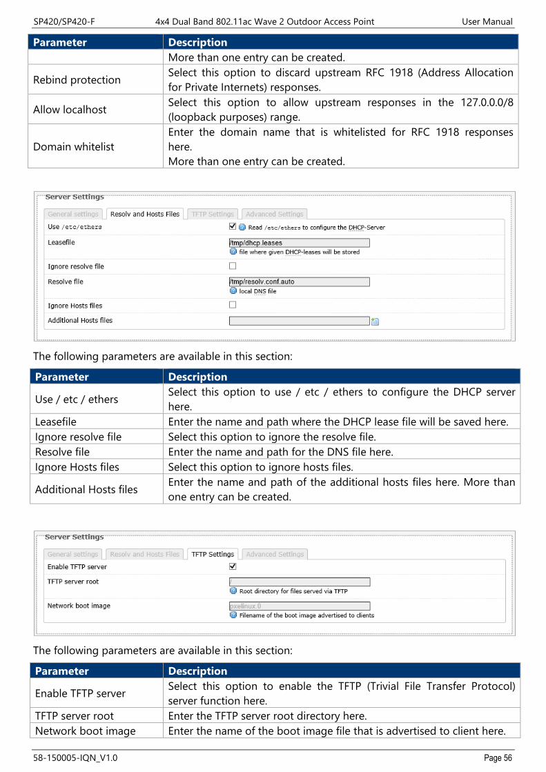
SP420/SP420-F 4x4 Dual Band 802.11ac Wave 2 Outdoor Access Point User Manual
58-150005-IQN_V1.0 Page 56
Parameter Description More than one entry can be created.
Rebind protection Select this option to discard upstream RFC 1918 (Address Allocation for Private Internets) responses.
Allow localhost Select this option to allow upstream responses in the 127.0.0.0/8 (loopback purposes) range.
Domain whitelist Enter the domain name that is whitelisted for RFC 1918 responses here. More than one entry can be created.
The following parameters are available in this section:
Parameter Description
Use / etc / ethers Select this option to use / etc / ethers to configure the DHCP server here.
Leasefile Enter the name and path where the DHCP lease file will be saved here. Ignore resolve file Select this option to ignore the resolve file. Resolve file Enter the name and path for the DNS file here. Ignore Hosts files Select this option to ignore hosts files.
Additional Hosts files Enter the name and path of the additional hosts files here. More than one entry can be created.
The following parameters are available in this section:
Parameter Description
Enable TFTP server Select this option to enable the TFTP (Trivial File Transfer Protocol) server function here.
TFTP server root Enter the TFTP server root directory here. Network boot image Enter the name of the boot image file that is advertised to client here.

SP420/SP420-F 4x4 Dual Band 802.11ac Wave 2 Outdoor Access Point User Manual
58-150005-IQN_V1.0 Page 57
The following parameters are available in this section:
Parameter Description Filter private Select this option not to forward reverse lookups for local networks.
Filter useless Select this option not to forward requests that cannot be answered by public name servers.
Localize queries Select this option to localize the hostname depending on the requesting subnet if multiple IP addresses are available.
Expand hosts Select this option to add a local domain suffix to the names served from the hosts files.
No negative cache Select this option not to cache negative replies.
Strict order Select this option to only query DNS server in the order specified in the "resolvfile".
Bogus NX Domain Override
Enter the IP addresses of the host that supply bogus NX domain results here. More than one entry can be created.
DNS server port Enter the TCP/UDP port number for the DNS server connection here. This port is used for inbound DNS queries.
DNS query port Enter the TCP/UDP source port number for outbound DNS queries here.
Max. DHCP leases Enter the maximum number of active DHCP leases allowed here.
Max. EDNS0 packet size Enter the maximum size allowed for EDNS.0 (Extension mechanisms for DNS) UDP packets here.
Max. concurrent queries Enter the maximum number of concurrent DNS queries allowed here.

SP420/SP420-F 4x4 Dual Band 802.11ac Wave 2 Outdoor Access Point User Manual
58-150005-IQN_V1.0 Page 58
The following parameters are available in this section:
Parameter Description Hostname Displays the hostname of the active DHCP lease. IPv4/MAC Address Displays the IPv4/MAC address of the active DHCP lease. Leasetime remaining Displays the lease time remaining for the active DHCP lease.
The following parameters are available in this section:
Parameter Description Hostname/IPv6 Address/DUID/ Leasetime remaining
Displays the hostname/IPv6 Address/DUID/ Leasetime remaining of the active DHCPv6 lease.
The following parameters are available in this section:
Parameter Description Hostname/MAC Address/ IPv4 Address
Enter the hostname/MAC Address/ IPv4 Address for the static DHCP client lease here.
4.3.3.4. Static Routes This page is used to display and configure static IPv4/IPv6 routes on the AP.
The following parameters are available in this section:

SP420/SP420-F 4x4 Dual Band 802.11ac Wave 2 Outdoor Access Point User Manual
58-150005-IQN_V1.0 Page 59
Parameter Description
Interface Select the interface for the static IPv4 route here. Options to choose from are lan and wan.
Target Enter the target IPv4 address or IPv4 network address for the static IPv4 route here.
IPv4 Netmask Enter the IPv4 subnet mask for the static IPv4 route here. IPv4 Gateway Enter the IPv4 address of the gateway for the static IPv4 route here. Metric/MTU Enter the metric/MTU for the static IPv4 route here.
The following parameters are available in this section:
Parameter Description
Interface Select the interface for the static IPv6 route here. Options to choose from are lan and wan.
Target Enter the target IPv6 address or network CIDR (Classless Inter-Domain Routing) for the static IPv6 route here.
IPv6 Gateway Enter the IPv6 address of the gateway for the static IPv6 route here. Metric/MTU Enter the metric/MTU for the static IPv6 route here.
4.3.3.5. Diagnostics This page provides useful network utilities that can be used to troubleshoot network connectivity between the AP and other networking nodes.
The following parameters are available in this section:
Parameter Description
Ping To use the ping utility, enter an IPv4/IPv6 address or domain name in the textbox and click the Ping button. The ping utility is used to send an ICMP request to nodes to probe if the node is active or not.
Traceroute To use the traceroute utility, enter an IPv4 address or domain name in the textbox and click the Traceroute button. This is used to display the route across the IP network and measure the transit delays of

SP420/SP420-F 4x4 Dual Band 802.11ac Wave 2 Outdoor Access Point User Manual
58-150005-IQN_V1.0 Page 60
Parameter Description packets from hop to hop.
Nslookup
To use the nslookup (name server lookup) utility, enter an IPv4 address or domain name in the textbox and click the Nslookup button. This is used to querying the DNS to obtain domain name mapping, IP address mapping, and/or DNS records.
After clicking the Ping button, the following page will appear:
After clicking the Traceroute button, the following page will appear:
After clicking the Nslookup button, the following page will appear:

SP420/SP420-F 4x4 Dual Band 802.11ac Wave 2 Outdoor Access Point User Manual
58-150005-IQN_V1.0 Page 61
4.3.3.6. Firewall This page is used to display and configure the firewall settings on the AP.
The following parameters are available in this section:
Parameter Description Enable SYN-flood protection
Select this option to enable the SYN-flood protection function. SYN stands for the synchronize step in the TCP three-way handshake.
Enable vap isolate Select this option to enable the VAP (Virtual Access Point) isolate function.
Drop invalid packets Select this option to enable the firewall function that will drop invalid received packets in the firewall zone.
Input Select the input (incoming) action here. Options to choose from are reject, drop, and accept.
Output Select the output (outgoing) action here. Options to choose from are reject, drop, and accept.
Forward Select the forwarding action here. Options to choose from are reject, drop, and accept.

SP420/SP420-F 4x4 Dual Band 802.11ac Wave 2 Outdoor Access Point User Manual
58-150005-IQN_V1.0 Page 62
The following parameters are available in this section:
Parameter Description Zone Forwarding Displays the visual flow for the firewall zone here.
Click the Add/Edit/Delete button to add/ delete a new or modify the existing firewall zone.
After clicking the Add button, the following page will appear:
The following parameters are available in this section:
Parameter Description Name Enter the name for the firewall zone here.
Input Select the input (incoming) action here. Options to choose from are reject, drop, and accept.
Output Select the output (outgoing) action here. Options to choose from are reject, drop, and accept.
Forward Select the forwarding action here. Options to choose from are reject, drop, and accept.
Masquerading Select this option to enable the masquerading function on the firewall zone.
MSS clamping Select this option to enable the MSS clamping function on the firewall zone.
Covered networks Select the interface that is included in this firewall zone here. Multiple interfaces can be selected. Select the create option to create a new interface for the firewall zone. Enter the name for the new interface in

SP420/SP420-F 4x4 Dual Band 802.11ac Wave 2 Outdoor Access Point User Manual
58-150005-IQN_V1.0 Page 63
Parameter Description the space provided.
The following parameters are available in this section:
Parameter Description
Restrict to address family Select the IP address family that will be restricted here. Options to choose from are IPv4 and IPv6, IPv4 only, and IPv6 only.
Restrict Masquerading to given source subnets
To restrict the masquerading function to a given source subnet, enter the IPv4 subnet of the source here. This option is not available for the IPv6 address family. More than one entry can be created.
Restrict Masquerading to given destination subnets
To restrict the masquerading function to a given destination subnet, enter the IPv4 subnet of the destination here. This option is not available for the IPv6 address family. More than one entry can be created.
Force connection tracking Select this option to force connection tracking. Enable logging on this zone Select this option enable logging on this firewall zone.
Limit log messages To limit log messages, enter the time limit here.
The following parameters are available in this section:
Parameter Description Allow forward to destination zones
Select the destination zone here. Traffic is forwarded to this zone from the "newzone".

SP420/SP420-F 4x4 Dual Band 802.11ac Wave 2 Outdoor Access Point User Manual
58-150005-IQN_V1.0 Page 64
Parameter Description Allow forward from source zones
Select the source zone here. Traffic is forwarded from this zone to the "newzone".
4.3.3.7. Bluetooth This page is used to display and configure the Bluetooth settings on the AP.
4.3.3.8. Externalvlan This page is used to enable VLAN transparent transmission settings on the AP.

SP420/SP420-F 4x4 Dual Band 802.11ac Wave 2 Outdoor Access Point User Manual
58-150005-IQN_V1.0 Page 65
TECHNICAL SPECIFICATIONS Chapter 5.Physical
Dimensions (L x W x H)
296 x 92 x 283 mm (11.65 x 3.62 x 11.41 in)
Weight 2000 grams (4.4 lbs.)
SP420 SP420-F
WAN/PoE In Port One 10/100/1000 Mbps port One 10/100/1000 Mbps port
LAN Port One 10/100/1000 Mbps port One 10/100/1000 Mbps SFP
Antenna 2.4GHz: Embedded 5dBi omni antennas 5GHz Embedded 5dBi omni antennas
Power Supply DC 48V, 0.5A PoE
LAN/PoE Out 48V/10 Watts (Max.), Passive PoE (Pairs 4, 5+; 7, 8 Return), (SP420 Only)
Power Consumption Max. 13.5 Watts
Wireless
Frequency Bands
2.4GHz Radio 5GHz Radio
US 2.412 – 2.462GHz 5.15GHz – 5.35GHz 5.47GHz – 5.85GHz
EU 2.412 – 2.472GHz 5.15GHz – 5.35GHz 5.47GHz – 5.725GHz
Japan 2.412 – 2.472GHz 5.15GHz – 5.35GHz 5.47GHz – 5.725GHz
China 2.412 – 2.472GHz 5.15GHz – 5.35GHz 5.725GHz – 5.85GHz
India 2.412 – 2.472GHz 5.15GHz – 5.35GHz 5.725GHz – 5.85GHz 5.85GHz – 5.875GHz
Operating Channels
2.4GHz Radio 5GHz Radio
US 1 – 11 36, 40, 44, 48, 52, 56, 60, 64, 100, 104, 108, 112, 116, 132, 136, 140, 149, 153, 157, 161, 165
EU 1 – 13 36, 40, 44, 48, 52, 56, 60, 64, 100, 104, 108, 112, 116, 132, 136, 140
Japan 1 – 13 36, 40, 44, 48, 52, 56, 60, 64, 100, 104, 108, 112, 116, 132, 136, 140
China 1 – 13 36, 40, 44, 48, 52, 56, 60, 64, 149, 153, 157, 161, 165
India 1 – 13 36, 40, 44, 48, 52, 56, 60, 64, 149, 153, 157, 161, 165, 169, 173
Bandwidth Rate 2.4GHz: 20 / 40 MHz 5GHz: 20 / 40 / 80 MHz
Wireless Security Security: Open System, 802.1x, WPA-PSK/WPA2-PSK WPA-Enterprise/WPA2-Enterprise

SP420/SP420-F 4x4 Dual Band 802.11ac Wave 2 Outdoor Access Point User Manual
58-150005-IQN_V1.0 Page 66
Wireless Extensible Authentication Protocol (EAP) types: EAP-Transport Layer Security (TLS) EAP-Tunneled TLS (TTLS) Protected EAP (PEAP) EAP-Subscriber Identity Module (SIM) *Above partial functions should be configured by Z-COM Wireless LAN Controllers (WLC)
Operating Mode Thin AP (TAP) / Fat AP (FAP) Wireless SSIDs 2.4 GHz (Up to 8 SSIDs), 5.8 GHz (Up to 8 SSIDs)
Bluetooth Low Energy
BLE 4.1
Frequency 2400-2480MHz
Antenna 1.5dBi (Embedded)
Compliance Standards
IEC/EN 60950 EN55032 & EN55024 EN 62311 & EN 50385 WEEE & RoHS Radio approvals: EN 300 328, EN301 893 (Europe) EN 301 489-1 and -17 (Europe) SRRC (China) IEEE standards: IEEE 802.11a/b/g/n/ac IEEE 802.11d, e, h, i, j, k, r, u, v time stamp, w, and z standards IEEE 802.3i, u, ab IEEE 802.3af, at (Powered Device) Multimedia: Wi-Fi multimedia (WMM)
Environmental
Temperature Humidity
Operating -40°C to 70°C (-40°F to 158°F) 10% to 90% (Non-condensing)
Storage -40°C to 80°C (-40°F to 168°F) 10% to 90% (Non-condensing)

SP420/SP420-F 4x4 Dual Band 802.11ac Wave 2 Outdoor Access Point User Manual
58-150005-IQN_V1.0 Page 67
APPENDIX Chapter 6. Warranty 6.1.
General Warranty 6.1.1.The warranty period stated below replaces the warranty period as stated in the user manuals for the relevant Products. If there is no proof indicating the purchase date, the manufacture date shall be considered as the beginning of the warranty period. The Warranty extends only to the original end-user purchaser and is not transferable to anyone who obtains ownership of the Product from the original end-user purchaser.
1. Z-COM provides one year of conditional warranty depends on different models. 2. Lifetime warranty covers product itself, excluding consumable products, accessories, second-
hand products, and software. Lifetime warranty is only effective when products are still in the Z-COM Product list. After the EOL (End of Life) announcement for any Products, the warranty will be one year from the date of such Product EOL announcement. To grant the lifetime warranty, Products should have a proof of purchase (such as the invoice or sales receipt) must be provided upon receiving warranty service. The standard warranty period for any Product had a proof of purchase shall be one year from the date of purchase or manufacture.
3. Products are considered as DOA (Dead on Arrival) after conclusive test within the first 30 days of its shipping date from Z-COM. After 30 days from the shipping date, defective products covered within the warranty are considered as RMA (Return Material Authorization).
4. Z-COM reserves the right to inspect all defective products which must be returned and paid shipping fee by purchasers.
Warranty Conditions 6.1.2.Warranty service will be excluded if following conditions occurred:
1. The product has been tampered, repaired and/or modified by non-authorized personnel 2. The SN (Serial Number) or MAC (Media Access Control) address has been changed, cancelled,
or removed 3. The damage is caused by third party software or virus 4. The software loss or data loss that may occur during repair or replacement
Disclaimer 6.1.3.PRODUCTS ARE NOT WARRANTED TO OPERATE UNINTERRUPTED OR ERROR FREE. Z-COM NEITHER ASSUMES NOR AUTHORIZES ANY OTHER PERSON TO ASSUME FOR IT ANY OTHER LIABILITY IN CONNECTION WITH THE SALE, INSTALLATION, MAINTENANCE OR USE OF ITS PRODUCTS. Z-COM SHALL NOT BE LIABLE UNDER THIS WARRANTY IF ITS TESTING AND EXAMINATION DISCLOSE THE ALLEGED DEFECT IN THE PRODUCT DOES NOT EXIST OR WAS CAUSED BY CUSTOMER’S OR ANY THIRD PERSON’S MISUSE, NEGLECT, IMPROPER INSTALLATION OR TESTING, UNAUTHORIZED ATTEMPTS TO REPAIR, OR ANY OTHER CAUSE BEYOND THE RANGE OF THE INTENDED USE, OR BY ACCIDENT, FIRE, LIGHTNING, FOREC MAJEURE EVENT OR ANY OTHER HAZARD. THE INFORMATION CONTAINED HEREIN IS SUBJECT TO CHANGE WITHOUT NOTICE.

SP420/SP420-F 4x4 Dual Band 802.11ac Wave 2 Outdoor Access Point User Manual
58-150005-IQN_V1.0 Page 68
Compliance Information 6.2. RF Exposure Warning 6.2.1.
The antennas used for this transmitter must be installed to provide a separation distance of at least 20 cm from all persons and must not be located or operating in conjunction with any other antenna or transmitter.
CE Marking 6.2.2.CE marking on this product represents the product is in compliance with all directives that are applicable to it.
Note: This device meets Max. TX power limit per ETSI regulations.
RoHS/WEEE Compliance Statement 6.2.3.
European Directive 2012/19/EU requires that the equipment bearing this symbol on the product and/ or its packaging must not be disposed of with unsorted municipal waste. The symbol indicates that this product should be disposed of separately from regular household waste streams. It is your responsibility to dispose of this and other electric and electronic equipment via designated collection facilities appointed by the government or local authorities. Correct disposal and recycling will help prevent potential negative consequences to the environment and human health. For more detailed information about the disposal of your old equipment, please contact your local authorities, waste disposal service, or the shop where you purchased the product.
Declaration of Conformity 6.3.Hereby, Z-COM, Inc. declares that the radio devices are in compliance with Directive 2014/53/EU. The full text of the EU declaration of conformity is available at the following internet address: https://www.zcom.com.tw/index/downloads?keyword=&meterial_type=56

SP420/SP420-F 4x4 Dual Band 802.11ac Wave 2 Outdoor Access Point User Manual
58-150005-IQN_V1.0 Page 69
Optional Accessories 6.4.PN Item Picture SP420 SP420-F
SP-CBM5 Anti-theft steel rope + allen wrench + four screws V V
SP-MKM5
Two-dimensional mounting kit • Two-dimensional mounting bracket • Pole-supported bracket • Intermediate steel plate • Two flat head screws • Four self-tapping screws • Four screw anchors • Four machine screws (M4) • Four machine screws (M5)
V V
SP-WP-CM20 Waterproof cable gland
V V
SP-WP-CM28SFP Waterproof cable gland for fiber port
V
SP-48063-XX 48V PoE Injector + power cord
V V
Note: When ordering power adaptors, you must specify the destination region by indicating -US, -EU instead of -XX.
Contact Information 6.5.All information may be changed by Z-COM at any time without prior notice or explanation to the user. For further information please refer to our website: www.zcom.com.tw