Embed Size (px)
Citation preview

Army National Guard Readiness Center Arlington, Virginia
Revised Thesis Proposal
P r e p a r e d B y : A m a n d a C . F a r a c e I S t r u c t u r a l O p t i o nP r e p a r e d F o r : D r . T h o m a s E . B o o t h b y J a n u a r y 1 5 , 2 0 1 0

Army National Guard Readiness Center Dr. Thomas E. Boothby Arlington, Virginia January 15, 2010
Amanda C. Farace Page 2
Table of Contents EXECUTIVE SUMMARY ....................................................................................................................................................... 3 INTRODUCTION .................................................................................................................................................................... 4 BACKGROUND ....................................................................................................................................................................... 5 EXISTING STRUCTURAL SYSTEM .................................................................................................................................... 6 FOUNDATION ........................................................................................................................................................................................... 6 COLUMNS .................................................................................................................................................................................................. 6 FLOOR SYSTEMS ...................................................................................................................................................................................... 7 ROOF SYSTEMS ........................................................................................................................................................................................ 8 LATERAL SYSTEM .................................................................................................................................................................................... 8
PROPOSED STATEMENT .................................................................................................................................................... 9 PROPOSED SOLUTION ........................................................................................................................................................ 9 SOLUTION METHODS ........................................................................................................................................................ 10 BREADTH TOPIC 1 – ARCHITECTURE ......................................................................................................................... 11 BREADTH TOPIC 2 – CONSTRUCTION MANAGEMENT .......................................................................................... 11 TASKS & TOOLS .................................................................................................................................................................. 12 SCHEDULE .............................................................................................................. ERROR! BOOKMARK NOT DEFINED. CONCLUSION ........................................................................................................................................................................ 15

Army National Guard Readiness Center Dr. Thomas E. Boothby Arlington, Virginia January 15, 2010
Amanda C. Farace Page 3
EXECUTIVE SUMMARY Depth Study: Steel Redesign The Army National Guard Readiness Center addition is an 8‐story joint headquarters building located in Arlington, Virginia. It consists of 3 underground levels, 5 above grade levels, and a mechanical penthouse. The building is constructed of cast‐in‐place concrete with ordinary reinforced shear walls. The building includes large data areas, a library fitness center, open office space and office suites, and sensitive areas protected by SCIFS. A large plaza at the 1T level doubles as a green roof. It is anticipated to reach a LEED silver rating. Due to the national significance of the building, the structural design of the Army National Guard Readiness Center Addition was guided by progressive collapse and blast requirements. For the purpose of this thesis, the problem of progressive collapse shall be reevaluated for an alternate steel framing system. With the added risk of terrorist attacks and other threats on the building’s structure, blast and explosion loading will also be considered for the new steel structure. Through research and analysis of various load cases and various collapse scenarios, the structure will be designed to protect the occupants from potential disasters. Breadth 1: Architectural The change in structural system from concrete to steel will inevitably impact the floor layouts. After the steel structure is redesigned and it becomes clear where it will impact the floor plans, spatial relation exercises such as bubble diagrams will be used to reconfigure the plans and create a working typical floor plan that fits with the proposed structure. Final drawings will be created using AutoCAD and will be included in the final report. Along with the floor plans, the building’s façade will also be affected by the change in structural layout. Sketches will be used to determine a viable solution to the façade. Breadth 2: Construction Management Curing time and formwork construction can be eliminated from the construction schedule when changing the structural system from concrete to steel. Procurement time however, may increase the construction time and must be considered as well. To account for this and other impacts the redesign will have on the project schedule and cost, an in‐depth analysis will be completed to determine if the proposed steel system is an economical alternative to the existing concrete structure. To ensure that this analysis is as accurate and true to life as possible, general contractors, sub‐contractors and vendors from the Arlington areal will be consulted.

Army National Guard Readiness Center Dr. Thomas E. Boothby Arlington, Virginia January 15, 2010
Amanda C. Farace Page 4
INTRODUCTION The Army National Guard Readiness Center headquarters addition sited to the south of the existing facility, where storm water retention ponds where previously located. Due to the loss of the retention pond, the project also includes the installation of storm water detention tanks. The new building is 82 feet above grade and approximately 251,000 square feet. The contract value was $100 million and is a Design-Bid-Build with Tompkins Builders, Inc., the general contractor, holding lump sum contracts with all subcontractors. The eight-story facility is comprised of 3 underground levels (Referred to as Levels 3P, 2P and 1P) and a 5 level tower component (Levels referred to as 1T – 5T) as well as a mechanical penthouse. The three underground levels account for the majority of the building’s square footage, with a much larger footprint than the above ground floors. The underground encompasses approximately 150,000 square feet and the five-story tower encompasses 100,000 square feet. This design was developed to increase the amount of green space since a large portion of the underground levels will be topped with an intensive green roof system. The addition is designed to meet Department of Defense Anti-Terrorism and Force Protection Requirements. This required that physical security measures, such as internal bracing to prevent progressive collapse, blast walls, berms, bollards and heavy landscape, to have been integrated into the design of the building. The facility is also expected to achieve LEED Silver Certification. LEED points are anticipated through the green roof system, offering bicycle storage and changing rooms, low-emitting and fuel efficient vehicles, reduction of water usage, water efficient landscaping, use of low-emitting as well as recycled and regional materials, and creating office space that can be 75% daylight. The building will incorporate open office spaces, general office suites, conference rooms, specialized compartmented information facilities, a fitness center, small library, and an auditorium. As a result of the location and the existing facilities that are on site, several other features have been incorporated into the project. This includes the installation of the storm water detention tanks, the relocation of an existing radio tower, relocation of existing gate, a one story bridge connecting the new facility with the existing headquarters, construction of a new mailroom, and a construction of a new multi-story parking facility. This report will focus on the new Army National Guard Readiness Center Addition and none of the other project features will be discussed or analyzed.
Army National Guard Readiness Center Dr. Thomas E. Boothby Arlington, Virginia January 15, 2010
Amanda C. Farace Page 5
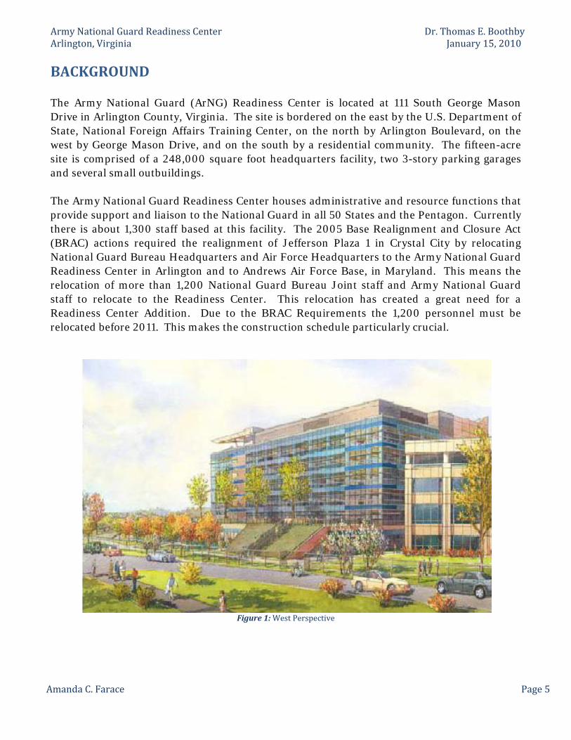
BACKGROUND The Army National Guard (ArNG) Readiness Center is located at 111 South George Mason Drive in Arlington County, Virginia. The site is bordered on the east by the U.S. Department of State, National Foreign Affairs Training Center, on the north by Arlington Boulevard, on the west by George Mason Drive, and on the south by a residential community. The fifteen-acre site is comprised of a 248,000 square foot headquarters facility, two 3-story parking garages and several small outbuildings. The Army National Guard Readiness Center houses administrative and resource functions that provide support and liaison to the National Guard in all 50 States and the Pentagon. Currently there is about 1,300 staff based at this facility. The 2005 Base Realignment and Closure Act (BRAC) actions required the realignment of Jefferson Plaza 1 in Crystal City by relocating National Guard Bureau Headquarters and Air Force Headquarters to the Army National Guard Readiness Center in Arlington and to Andrews Air Force Base, in Maryland. This means the relocation of more than 1,200 National Guard Bureau Joint staff and Army National Guard staff to relocate to the Readiness Center. This relocation has created a great need for a Readiness Center Addition. Due to the BRAC Requirements the 1,200 personnel must be relocated before 2011. This makes the construction schedule particularly crucial.
Figure 1: West Perspective

Army National Guard Readiness Center Dr. Thomas E. Boothby Arlington, Virginia January 15, 2010
Amanda C. Farace Page 6
EXISTING STRUCTURAL SYSTEM
Foundation The geotechnical report engineering survey was performed by CH2M Hill on April 21, 2008. In this study, it was found that a relatively high water level of approximately 6 feet to 10 feet below the existing surface was anticipated. As much as 35 feet of excavation were required to reach the building grades therefore, drilled in soldier piles with wood lagging and tied-back anchors was recommended for temporary excavation support as well as the installation of dewatering well points. CH2M Hill noted that, with proper ground water management and control, the existing subsurface is suitable for support of the building using a mat foundation system based on evaluation of allowable bearing capacity and anticipated settlement. The recommended allowable bearing capacity for the new building location was 4800 lbs/ft2 for a mat footing. As a result, a 43-inch concrete mat foundation was designed.
Columns A reasonably consistent column layout exists throughout the building even with the changes in the shape of the floors between level 3P and 1T. The typical interior gravity column is a 22-inch by 22-inch, reinforced normal weight concrete column. The strength of the concrete used in all columns is 4,000 pounds per square inch. While the size and shape of the column is the same on each floor, there are three changes in reinforcement. For levels 3P to 1P columns are reinforced with sixteen No. 10 vertical bars. These change after the 1P level where the tower component of the building begins. For levels 1T and 2T, columns are reinforced with sixteen #8 vertical bars. The reinforcement changes again at the 3T level up to the 5T level; these columns are reinforced with eight #8 vertical bars. #3 ties are located 12 inches on center at every level.
Figure 2: Typical Interior Column Figure 3: Typical Column Layout for Underground Levels

Army National Guard Readiness Center Dr. Thomas E. Boothby Arlington, Virginia January 15, 2010
Amanda C. Farace Page 7
Figure 4: Typical Column Layout for Tower Levels
Floor Systems The Army National Guard Readiness Center Addition utilizes a reinforced concrete structural system. All of the floors are two-way flat slab with column strips and edge beams along the eastern and northern walls of the Tower component. The typical concrete strength is 4,000 psi. The typical slab thickness is nine inches however; this changes in areas where the access flooring changes and for drainage areas in mechanical and electrical rooms. No. 6 and No. 8
bars are typically used for reinforcement in the floor systems. Due to the irregular shape of the building and the change in shape from the underground portion of the building to the tower component, a two-inch expansion joint is located at
the 3P to 1T levels along column line 6.2. This expansion joint makes the building act as almost two separate buildings, the tower portion and the plaza portion. The tower portion extends from level 3P to 5T while the plaza portion is comprised of the subgrade levels and topped off with an intensive green roof. This can be seen in figures 8 and 9.
Figure 6: Elevation showing location of expansion joint and relationship between Plaza portion and Tower portion
Figure 5: Location of Expansion Joint

Army National Guard Readiness Center Dr. Thomas E. Boothby Arlington, Virginia January 15, 2010
Amanda C. Farace Page 8
Roof Systems The penthouse roof of the tower is a two-way flat slab. The slab is 10” thick with a concrete strength of 4,000 pounds per square inch. This roof was designed to resist 30 pounds per square foot snow load and is reinforced with #5 bars at 12 inches on center and 18 inches on center. A large skylight over the northern stairs required steel framing, which consists of beams ranging from W12X14 to W12X26. The plaza roof is also a two-way slab with drop panels. The slab thickness ranges from eight inches to sixteen inches with a concrete strength of 4,000 pounds per square inch. This roof will act as an intensive green roof and therefore had to be designed to carry a 100-pound per square foot roof garden load. It is reinforced with #6 bars and includes a two-inch expansion joint where the roof abuts the floor of the first tower level (1T), as do the floors below.
Lateral System The lateral system for the ArNG Readiness Center consists of reinforced concrete shear walls. These walls have a thickness of twelve inches and a concrete strength of 4,500 pounds per square inch. The numbers of shear walls varies between levels due to the building’s change in footprint. Typical shear wall locations can be seen in figures 10 and 11 below. This system resists lateral loads in the north-south and east-west direction depending upon the orientation of the wall.
Figure 8: Typical Shear Wall Locations in Tower Levels
Figure 7: Typical Shear Wall Locations in Below Grade Levels

Army National Guard Readiness Center Dr. Thomas E. Boothby Arlington, Virginia January 15, 2010
Amanda C. Farace Page 9
PROPOSED STATEMENT The Army National Guard Readiness Center was designed as a cast‐in‐place concrete building with two‐way flat slab floors and normally reinforced concrete shear walls. From the analysis in previous technical reports, it was confirmed that the structural elements were sufficiently designed to carry the gravity and lateral loads. Another main consideration for structural engineers during the design process was the possibility of terrorist attacks and other threats. Like all government buildings that have been designed since the September 11th attacks, progressive collapse design and blast resistant requirements were required for the Army National Guard Readiness Center Addition. For the purpose of this thesis, the building will be re‐evaluated using a steel framing system and will include investigation into the progressive collapse capabilities. Blast and explosion loading will also be considered for the new structural system.
PROPOSED SOLUTION For the purpose of this thesis, The Army National Guard Readiness Center Addition will be re‐evaluated using a steel framing system and will include an investigation into the progressive collapse capabilities. Blas and explosion loading will also be considered for the new structural system. Only ground level structural threats will be addressed to the ease of accessibility. The redesign will include both a gravity system and a lateral system. The proposed gravity system will be a composite metal deck flooring system with steel framing. The composite metal deck utilizes the benefits of both materials. The deck will act as permanent formwork. It will also interlock with the concrete the serve as reinforcement for the concrete slab. The redesign of the lateral system will consist of steel moment frames. The new lateral system will be design using the seismic and wind loads that were found in previous technical reports. An optimum layout of frames will be determined based on the torsional effect created by these loads. The proposed structural changes from concrete to a steel system will result in an overall lighter structural system and therefore an analysis of the foundation will be required. In Technical Report III it was determined, by inspection, that uplift and overturning were not issues for the current concrete structure due to the weight and soil friction. However, with the reduction of weight from concrete to steel, overturning and uplift will need to be investigated to determine if the current flat slab foundation must be redesigned for the proposed steel structural system.
Army National Guard Readiness Center Dr. Thomas E. Boothby Arlington, Virginia January 15, 2010
Amanda C. Farace Page 10
SOLUTION METHODS The new gravity system of the Army National Guard Readiness Center Addition will be looked at first in the redesign. Vulcraft’s Steel Roof and Floor Deck design manual will assist in the proposed floor design. Beams and columns will be sized using the 13th Edition of AISC’s Steel Construction Manual. The live loads used in the design process will be taken from ASCE 7‐05 Chapter 2. An ETABS model will be generated to help analyze the proposed system. Hand calculations will be performed to compare member sizes determined by the ETABS model. The proposed lateral system will be considered next for the redesign. As in previous reports, the lateral system will be designed using ASCE 7‐05. Chapter 2 will be used for load combinations, chapter 6 will be used for wind loading, and chapters 11, 12, and 22 will be used for seismic loading. In an attempt to reduce the quantity of moment frames throughout the building, an optimization of where to place the new framing system will be performed. The ETABS model will be utilized to control the design and obtain the forces so that the drift of the building meets the ASCE 7‐05 requirements. AISC’s 13th Edition Steel Construction Manual will be used for all designs and LRFD method will be employed. The progressive collapse analysis will include the hypothetical loss of a primary structural element. Critical perimeter and interior members will be ‘lost’ and a structural analysis will be performed without the critical component. Since the structural elements were ‘lost’ due to a blast or destructive means, specific loading criteria will be utilized for the structural analysis. The results of the analysis will then be compared to the ultimate strength of the structural system to determine its efficiency if there were to be an attack or damage to the structural system. “The GSA – Progressive Collapse Guidelines” will be exploited for the progressive collapse and blast analysis. Since the properties of steel are a much different than the existing concrete structure, an examination of the vibration and acoustics at the 5T Level, below the mechanical penthouse, will also be completed if time permits.

Army National Guard Readiness Center Dr. Thomas E. Boothby Arlington, Virginia January 15, 2010
Amanda C. Farace Page 11
BREADTH TOPIC 1 – Architecture Structural alterations such as the complete change from a cast‐in‐place concrete system to a steel framing system will inevitably result in layout and architectural changes throughout the building. Changes to the column grid and different size columns will most likely impede on the existing floor layouts. These changes will need to be considered so that a typical floor plan can be redesigned where necessary. One important aspect is to retain the existing architectural program. This will require that any changes to the floor plans will still maintain the current spatial relationship. Bubble diagrams and other spatial relationship exercises will be used to explore alternatives and reconfigure the floor plans. Once a typical floor plan has been finalized, detailed sketches will be made using AutoCAD and will be included in the final report. While the floor plans will inevitably be affected, they are not the only architectural aspect that will need to be considered after the structural changes are made. Currently, the façade consists of precast and metal panels with ribbon windows. The anticipated change in column layout and column size wills likely cause changes to the façade. Also, the overall floor thickness will change, further changing the height of the façade and the “striping”. Possible new façade options will be investigated through the use of sketches taking into consideration the new steel framing.
BREADTH TOPIC 2 – Construction Management This breadth topic sill focus on the scheduling impact and cost‐related issues the will be affected by the proposed structural changes. Different erection and procurement time will be considered for the steel redesign as opposed to the existing cast‐in‐place concrete. Site logistics and crane configurations will also be investigated. A construction schedule will be generated using Microsoft Project and information gathered from steel manufacturers in the Arlington. VA area. The critical path of the proposed construction schedule will then be compared to that of the actual construction schedule to determine major scheduling impacts of the structural changes. A cost analysis of changing the structural system will also be conducted. A comparison of the cost savings of the proposed design will be studied. Any money saved, or extra money spent, on the steel system as well as cost savings due to scheduling changes will also be determined. Advantages and disadvantages of the steel system as compared to the existing concrete system will also be studied. A final conclusion will determine the actual constructability and feasibility of the proposed steel system.

Army National Guard Readiness Center Dr. Thomas E. Boothby Arlington, Virginia January 15, 2010
Amanda C. Farace Page 12
TASKS & TOOLS Task 1: Research Blast Loads and Effects ‐ Investigate properties of explosions and blasts ‐ Research blast scenarios to determine worst‐case effects ‐ Research possible solutions for steel framing ‐ Consider most sensitive areas and determine areas most susceptible to attack Task 2: Design Gravity Framing System ‐ Determine Live and Dead Loading ‐ Consider possible framing systems ‐ Determine preliminary member sizes Task 3: Design Lateral Framing System ‐ Determine lateral loads ‐ Consider possible framing systems ‐ Determine preliminary member sizes Task 4: Generate Computer Model ‐ Check strength requirements ‐ Check serviceability requirements Task 5: Design Progressive Collapse and Blast Resistant Components ‐ Determine blast load cases ‐ Determine progressive collapse load cases ‐ Employ blast and progressive load cases ‐ Check strength requirements ‐ Perform size upgrades as necessary Task 6: Breadth 1 ‐ Consider location of existing shear walls compared to new lateral system ‐ Determine areas significantly affected by proposed structural system ‐ Perform spatial relationship exercise to reconfigure problem areas ‐ Investigate changes and possible solutions to the facade ‐ Finalize floor plans and façade design Task 7: Breadth 2 ‐ Research preliminary redesign affects using RS Means ‐ Consult with the general contractor and obtain available information ‐ Determine the schedule changes created by the proposed system ‐ Consult with vendors and suppliers to determine procurement and erection timing ‐ Determine the cost implications of the proposed system

Army National Guard Readiness Center Dr. Thomas E. Boothby Arlington, Virginia January 15, 2010
Amanda C. Farace Page 13
Task 8: Conclude Analysis Result ‐ Finalize all member sizes ‐ Compare computer model analysis Task 9: Write Final Report Task 10: Develop Final Presentation

Army National Guard Readiness Center Dr. Thomas E. Boothby Arlington, Virginia January 15, 2010
Amanda C. Farace Page 14
PROGRESS LOG
* Note: If time permits a study of the vibration and acoustics below the mechanical penthouse will also be completed

Army National Guard Readiness Center Dr. Thomas E. Boothby Arlington, Virginia January 15, 2010
Amanda C. Farace Page 15
Conclusion This proposed thesis will focus on the analysis of the structural system of the Army National Guard Readiness Center Addition as a steel system and a comparison to the existing concrete structure. Progressive collapse and blast analysis will be highlighted in the redesign of the structural framing system. The foundation system will also be analyzed. The reduction in the weight of the building could allow for a decreased mat foundation. However, the overturning moment and uplift could become a more significant issue with the weight reduction and therefore increase the size of the foundation. Time permitting the steel framing system will also be analyzed for vibration and noise transmission at the mechanical penthouse level. Applicable codes will be referenced and utilized for all designs and analyses. The breadth topics of this study will include construction management and architectural studies. An in depth cost and schedule analysis will be completed for the construction management study. The results from the steel structure will be compared to that of the existing concrete to determine which system is more practical from a construction standpoint. The architectural study will take into account any changes to the existing column layout and structural sizes to develop new spatial relationships to fit the proposed structural system. The façade will also be analyzed for issues that may arise from the change in structural system and a new façade will be developed to fit the proposed system.