Embed Size (px)
Citation preview

Excess Energy from Heat-exchange Systems
Bin-Juine Huang, Ming-Li Tso, Ying-Hung Liu, Jong-Fu Yeh, Li-Tu Wu,
Yu-Hsiang Pan, Ching-Kang Huang, Mou-Yung Liao, Po-Hsien Wu
New Energy Center, Department of Mechanical Engineering,
National Taiwan University, Taipei, Taiwan
Corresponding author: [email protected]
1
The 23rd International Conferences on Condensed Matter Nuclear Science. June 9-11, 2021. Xiamen, China
Revised June 12, 2021

Outline of presentation
1. Cavitation and its power
2. Excess energy from triple-pipe heat exchanger (THX) heated by vapor-compression system (VCS)
3. Excess energy from double-pipe heat exchanger (DHX) heated by steam boiler
4. Conclusion
Q: Can excess energy be induced from a simple heat exchanging process involving cavitation, in kW scale?
2

1. Cavitation and its power
• Cavitation Phenomenon ➢Cavitation is a process of liquid vaporization at a pressure lower than
thermodynamic vapor pressure, which generates bubbles and creates implosion with intense shock wave or micro-jet to damage propeller or container wall etc .
Vapor bubble
formation and growth
No growth till surface breakdown
Bubble collapse with compression shock wave or micro jet (Implosion)
IET Institute for Energy Technology, HSR, Rapperswil, Switzerland
Propeller damage by cavitation (force and/or heat)
3

induces Low Energy Nuclear Reactions (LENR) ?
• Sonoluminescence (1934) • a LENR might occur inside extraordinarily large collapsing gas bubbles created in a
liquid during cavitation.
formation of bubble bubble growth quick and sudden contraction(implosion)
Sonoluminescence
Alan J. Walton, Geo. T. Reynolds. Sonoluminescence.
Advances in Physics, 1984, Vol. 33, No. 6, 595-660
Before collapse ~ 45 µm
➢flash generated by micro-bubble collapse in 5µs at ~5,100K• Cu foil in a 30W ultrasonic
vibrator for 7 & 21min• Failure mechanism: both
mechanical and thermal ?
21min
7min
4

Pressure inside micro/nano-bubbles
Diameter (2r) △P (Pa) △P (atm)
1mm 291.2 0.00287
500μm 582.4 0.00574
100μm 2,912 0.0287
50μm 5,824 0.0574
1μm 291,200 2.87
100nm 2,912,000 28.7
10nm 2.912x10⁷ 287
1nm 2.912x10⁸ 2,870
Strength of ‘bubble collapse’ (gas bubble dynamics)
5

Cavitation engine (Impact chamber)CONTROLLED CAVITATION ENERGY STEAM GENERATION (CCES)
Cavitation Energy Systems, lnc./New Energy Power System LLC
• Hydrodynamic cavitation: using conventional diesel fuel injector technology to inject a high-pressure water jet (20,000~25,000 psi at 1700 m/s) into a chamber to create cavitation and induce LENR
https://www.youtube.com/watch?v=Ji0GAt-q2EM&list=PLZk-jCLezj9hltBOsOUtri4W_71MbX8xU&index=14
Ejection creates cavitation micro-bubbles which collides with the wall.
Impact Chamber
6

Measured COP= 5.25 @388 oC
7

Energy revolution is coming, if
100 MWCES
1000MW heat
Power Generator
400 MW electricity@40% eff
300 MWNet electrical output
600 MW waste heatfor water desalination
100 MW
COP= 10 @>400 oC using water as fuel
ITER (2035) – 20,000 Million Euro
?COP=10
8

Research of Cavitation Machinesin National Taiwan University
(2018~)
• Use engineering approach according to two phenomena: 1) Cavitation2) Dynamic implosion using nanobubbles
• Develop two cavitation machines having COP > 1 (excess energy)1) Triple-pipe heat exchanger heated by vapor-compression system (VCS)2) Double-pipe heat-exchange heated by steam boiler (DHX)
9

2. Excess energy from triple-pipe heat exchanger heated by vapor-compression system (VCS)
- Continue testing vapor-compression system (VCS) presented in ICCF-22/Italy (2019)
10
Triple-pipe heat exchanger(THX) is heated by vapor compression system (VCS)
• Compressor: R22/2.75RT (3 kW input)
• No evaporator as in air conditioning system
• Use triple-pipe heat exchanger (THX)
Steady-state energy balance of VCS: Qwnet = Wt - QL
(First law of thermodynamics)11
Cold water
Refrigerant vapor
Hot steam
Energy Input Wt
Heat output from water
Qwnet
Triple-pipe Heat Exchanger (THX)
Compressor Heat Loss QL
triple-pipe heat exchanger
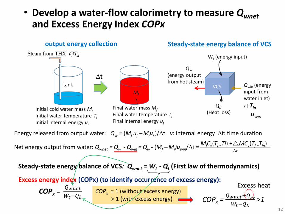
• Develop a water-flow calorimetry to measure Qwnet
and Excess Energy Index COPx
VCS
Wt (energy input)
Qw
(energy output from hot steam)
Qwin (energy input from water inlet)
at Tin
uwin
Initial cold water mass Mi
Initial water temperature Ti
Initial internal energy ui
Final water mass Mf
Final water temperature Tf
Final internal energy uf
Steam from THX @Tsi
tank
Tf
Mf
QL
(Heat loss)
Steady-state energy balance of VCSoutput energy collection
Net energy output from water: Qwnet = Qw - Qwin = Qw - (Mf –Mi)uwin/∆t =MiCv(Tf −Ti) +△MCv(Tf −Tin)
∆𝑡
Energy released from output water: Qw = (Mf uf –Miui )/∆t u: internal energy ∆t: time duration
COPx = 𝑄𝑤𝑛𝑒𝑡
𝑊𝑡−𝑄𝐿
Excess energy index (COPx) (to identify occurrence of excess energy):
COPx = 1 (without excess energy)> 1 (with excess energy)
Steady-state energy balance of VCS: Qwnet = Wt - QL (First law of thermodynamics)
COPx = 𝑄𝑤𝑛𝑒𝑡+𝑄𝑒𝑥
𝑊𝑡−𝑄𝐿>1
Excess heat
12
∆t

13
• VCS-1 was tested for 2 years under various operating conditions. • Test result shows that COPx >1 (excess energy) exists and can be repeated. COPx = 1.29~1.97.
• The compressor (Copeland) breaks down at the end of 2020 due to overheating.• Replacing compressor with different models (VCS-2), COPx is improved after tuning for
about 5 months. Maximum COPx is 2.05.
Test results of VCS

Excess heat (Qex)and total heat output (Qout) in kW scale
14

15
• For VCS-1, COPx is related to the temperature gradient (∆T) of two streams in THX.➢Higher inlet water temperature results in lower temperature gradient (∆T) between water
and freon in THX which affects the cavitation phenomena.
• For VCS-2, it seems not so.
Strong cavitation Weak cavitation(high ∆T) VCS-1 (low ∆T)
0.8
1.0
1.2
1.4
1.6
1.8
2.0
2.2
2.4
0 5
10
15
20
25
30
35
40
45
50
55
CO
Px
Inlet water temperature, oC
max COPx 2.05
2019/5/29 - 2021/6/12 (VCS-1, VCS-2)
2.05 (2021/6/12)
2021/6/11
VCS-1
VCS-2a
No excess energy if COPx <1.2(worst experimental error)
expected for VCS-2b after fine tuning

Several peculiar phenomena were observed1) Output steam temperature, 150oC, is higher than the compressor output
refrigerant temperature (146oC) - Excess energy was generated in water. And instead, the refrigerant vapor is cooled at some part of the heat exchanger.
2) Abnormally-high water line pressure (> 50 bar) was observed which broke the pressure gauge. Implies cavitation bubbles size ~ 50 nm (according to bubble dynamics). And, copper pipe was cracked and leaked.
3) Serious fouling happens even in a day causing blockage of water passage.
4) Refrigerant oil in VCS plays some role in heat transfer inside the triple-pipe heat exchanger and causes interesting heat transfer phenomena. Looks like the behaviour of oscillating heat pipes.
16
Cold water (10-50oC)Refrigerant flow
Hot steam
Energy Input Wt
Heat output by water
Qwnet
Triple-pipe Heat Exchanger (THX)
Compressor Heat Loss QL
150oC146oC
Heat flux inside THX
40-60oC

3. Excess energy from double-pipe heat exchanger (DHX) heated by steam boiler
17

• Double-pipe heat exchanger (DHX) design➢Using double-pipe heat exchanger to reduce manufacturing cost➢Using steam boiler as the heat source for future large-scale application
COPx = 1 (without excess energy)> 1 (with excess energy)
𝐶𝑂𝑃𝑥 = 𝑄𝑤𝑛𝑒𝑡+Q𝐿𝑥+𝑄𝑒𝑥
𝑊𝑡−𝑄𝐿 −𝑄𝑐>1
Excess heat
18
110~130o
5 kW
Energy balance of DHX: Wt - QL – Qc = Qwnet + QLx
Excess Energy Index: COPx= 𝑄𝑤𝑛𝑒𝑡+𝑄𝐿𝑥
𝑊𝑡−𝑄𝐿 − 𝑄𝑐
Qxin Qxout=If Qex (excess heat) =0
DHX
DHX
Water passage

COPx =1.55~2.55
• DHX-1 has been tested since July, 2020 under various operating conditions such as flowrates, steam temperature, water pressure, control schemes, etc.
• The first 4 months got nothing special (COPx=1) until November, 2020.(as baseline calibration)• The best performance of DHX-1 was found during 2020/11/14 - 2020/12/24 having excess
energy COPx = 1.50~2.55. Estimated cavitation bubbles size 20~30 nm.• Copper pipe rupture and leakage was found in Feb, 2021, 6 months after installation.• New DHX-2 (new design for stronger structure) cannot repeat the best results of DHX-1.
Maximum COPx = 2.55
Results of COPx ≈ 1 can be treated as the baseline calibration of the test bed.
Test under pipe rupture and leakage
19

0
1
2
3
4
5
6
110 115 120 125 130 135
Steam temperature from boiler, oC
2020/11/14 - 2020/12/24 (DHX-1)
Excess heat generation Qex (kW)
Boiler heat input Wt (kW)
• The excess energy generation Qex ranges 2.15-4.18 kW which varies with boiler steam temperatures.
𝐶𝑂𝑃𝑥 = 𝑄𝑤𝑛𝑒𝑡+Q𝐿𝑥+𝑄𝑒𝑥
𝑊𝑡−𝑄𝐿 −𝑄𝑐>1
Excess heat > 0
First-Law Energy Balance: Wt - QL – Qc = Qwnet + QLx
Qxin Qxout=
Qex =Qxout -Qxin
20

Peculiar phenomena observed in DHX-1• The inner copper pipe (steam side) of DHX-1 was found deformed and the outer pipe
wall (water side) was cracked and leaked, after a few hours’ operation.
• The outside surface of the inner pipe (thickness 0.4mm) became shining black which contains 10-23% carbon and 20-28% oxygen.
• A huge pressure (>160 bar) or a high temperature (>500oC) results in buckling of inner pipe and rupture of outer pipe that was probably induced by LENR.
Inner pipe buckling
Normal pipe
Inner pipe buckling
21

Element chemical analysis of outside surface (wt%)Original copper pipe 1-1 1-10
C: 10~23% O: 20~28%
Nuclear transmutation ?
SEM resultsOriginal Cu pipe
Buckled Cu pipe (1-1)
Buckled Cu pipe (1-10)
C (wt %) average 5.78 17.41 16.16
O (wt %) average 2.80 19.37 22.24
Cu (wt %) average 91.1 62.74 60.83 22

• Buckling of copper pipe caused by huge pressure or high temperature
• Outside surface looks shinning black
Buckling
Shinning black surface
SEM resultsOriginal Cu pipe
Buckled Cu pipe (1-1)
Buckled Cu pipe (1-10)
C (wt %) average 5.78 17.41 16.16
O (wt %) average 2.80 19.37 22.24
Cu (wt %) average 91.1 62.74 60.83
Where does carbon and oxygen come from ? Transmutation ? 23

The pipe surface looks like copper oxide nanowires made from thermal oxidation.
300°C,4h
600°C,4h
800°C,4h700°C,4h
500°C,4h
400°C,4h
Xu et al, Chemical Physics Letters 399 (2004) 62–66.Formation of CuO nanowires on Cu foil.
“CuO nanowires” seems formed at 500~700oC which causes copper tube deformation (buckling).
Specimen No.1-1
Scanning Electron Microscopy Image (SEM)
24
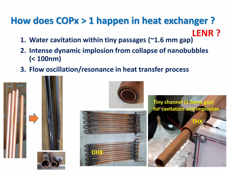
How does COPx > 1 happen in heat exchanger ?
1. Water cavitation within tiny passages (~1.6 mm gap)
2. Intense dynamic implosion from collapse of nanobubbles (< 100nm)
3. Flow oscillation/resonance in heat transfer process
Tiny channel (1.6mm gap) for cavitation and implosion
DHX
THX
LENR ?
25

4. Conclusion1) Excess energy in kW scale can be induced from simple heat exchanging
process involving cavitation.
2) The test results of the present heat-exchange systems (VCS and DHX) shows that COPx > 1 exists under some design and operating conditions, which makes water become fuel.
3) The excess energy index (COPx) is defined on the basis of 1st law of thermodynamic and can be used in the experimental data analysis to identify the existence of excess energy phenomena.
4) Material problems will be eventually encountered for the machines with COPx >1 since extremely high pressure or high temperature will be induced by LENR.
5) The phenomenon of COPx > 1 is related to cavitation, nano-bubbles implosion, and possible LENR. More research by scientists are needed.
6) As engineering people, we are focusing on the duplication of the best performance obtained during the studies to provide a reliable, simple and cheap machine to harvest energy from water.
• Current task: - try to repeat the best results (COPx = 2.55 or higher) of DHX-1,
and leave the material problem to future engineering development. 26
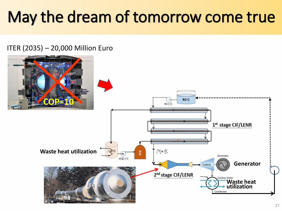
May the dream of tomorrow come true
COP=10
Generator
Waste heat utilization
Waste heat utilization
ITER (2035) – 20,000 Million Euro
27
Thank you
28
Bin-Juine Huang, Distinguished ProfessorNew Energy Center, Department of Mechanical Engineering, National Taiwan University, Taipei, TaiwanEmail: [email protected]
Acknowledgement – The present study is supported by Ministry of Science and Technology, Taiwan.