Embed Size (px)
Citation preview

3 Slot Payphone Controller
Building a Coin Relay Controller – Design S2BInstruction Manual and Safety Precautions
It is very important that for your safety and well being thatyou fully understand all the safety precautions BEFOREyou start building this controller. Read this bookletcompletely before you start this project.
When telephone companies installed a pay phone theyconnected a ground wire from the metal shell of thetelephone to a known good ground, a cold water pipe(assuming you do not use plastic water pipe!) or a groundrod. You should attach a ground wire of #16 or largergauge wire from the metal case of your payphone andconnect it to a known good ground.
This circuit uses a 24 Volt AC plug in UL APPROVEDtransformer and a fuse, do not substitute. The powersupply for the coin relay is about 100 Volts DC and cancause a shock. DO NOT touch the circuit when it itenergized and make sure you understand precautionswith working with high voltage. You can get a shock! Ifyou are not sure about safety around high voltages, donot build this project and do not install it.
DO NOT IGNORE THESE IMPORTANT SAFETYINSTRUCTIONS – THEY ARE FOR YOUR SAFETY
One of the original patents --- US 2,043,201
This Telephone is Property of
____________________________________________________
____________________________________________________
Information on your Telephone – For Your Records
Manufacturer __________________________
Date of Original Manufacture _____________
Drawing Reference _____________________
_____________________________________
_____________________________________
_____________________________________
The 3 Slot Payphone -- Part of American History
oldphoneguy.net
SC
oin
Con
trolle
r5B
2C
5B2C
112
Revised from Original
FOLL
OW
ALL
SAFE
TYPR
ECAT
ION
S
2010
Col
inT.
Cha
mbe
rsC
oinM
SW
341
Sec
ond
Edi
tion
2010 Colin T. Chambers

The Controller
The Controller will collect OR return coins that are deposited. There isonly one choice in the simple controller, return is suggested. (Reversethe leads to the Coin Relay to control the collect or return function.)
Power is provided by a 24 Volt AC wall transformer. This is changed toDC. The power supply provides approximately 35 Volts DC and 100Volts DC. The Coin Relay has a must operate specification of 60 VoltsDC with a full hopper of coins.
This controller is for use on more modern pay phones with a set ofcontacts on the Coin Relay that short the pulsing contacts on a rotarydial, or prevent a tone dial from working. This is NOT a “Dial ToneFirst” Pay Phone, they may NOT have the shorting contacts. Older payphones also may not have shorting contacts that prevent dialing.
In the olden days, pay phones used ground start telephone lines withall the “smarts” in the central office. This controller will simulate that,but only to a very simple extent.
Have you read the safety information? Do you fully understand it?Proceed only if you can answer yes to these two questions!
Here is a breadboard picture of what you are going to build. You shoulddo a breadboard FIRST then build it
Thanks to Bill Geurts for the picture and assistance in design
Notes
September 10, 2010
Remember – High Voltage Can Be Dangerous
oldphoneguy.net
112
You can use this controller to operate any number of payphones. Just use ONE at a time!
If you plan to built this – contact me!Colin T. Chambers – [email protected]

The drawing illustrates the basic connections. The circuit is built in theexternal box, this is safer.
The fuse and the RX (Fuse Resistor) are inside the box.
It may be possible to build the circuit inside the phone if you do some“pre-engineering” when it comes to space. The space inside the phoneis limited and will vary from pay phone to pay phone. The distance youcan go between the pay phone and external box is at least 200 feet. It isbest to locate the box near the phone and use a mod cord forconnections.
The earth ground is a requirement for your safety. This was done onALL telephone company installations.
If you are TOTALLY familiar with your house wiring and the ground atthe power outlets you may use this ground, but it must lead to a groundrod.
24VAC
PhoneCompany
Wall Outlet
GroundRod
Basic Connection DrawingFor Placing Circuit in Telephone
#16 Gauge WireOr heavier
Tip – Green Ring – RedCoin Relay on Yel Blk
BOX
A Good Ground is a Requirement
3
SAFETY SAFETY SAFETY
Earth Line
Rod is in 8 feet of moist earth
Automatic Electric – 3 Slot DrawingTypical Generic Schematic – Later Version
10
On
this
phon
e,ru
new
ires
form
3an
d4
ofth
eco
inre
lay,
disc
onne
ctin
gor
igin
alw
ires
on3
and
4
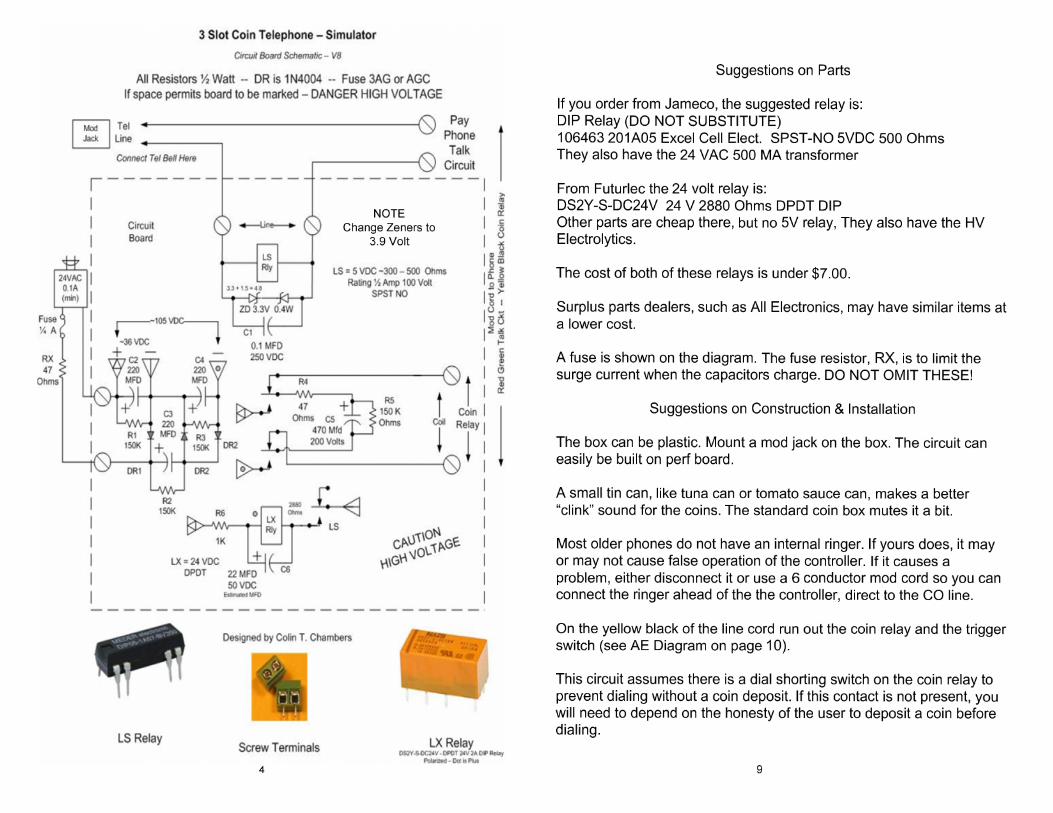

Parts List
LS Relay – Line Sense – 5 VDC SPST NO Rated ½ Amp 100 VDC, Coilresistance between 300 and 500 ohms. DIP size, similar to an ICLX Relay – Line Hold – 24 VDC DPST 2 Amp, Coil resistance between1500 and 2800 Ohms. NO diode on the coil, some relays may bepolarized, read the data sheets.
ZD – Zener Diode – Limits voltage across LS relay. 3.3 Volts 400 mW.In this configuration voltage drop across relay is max 4.8 VDC.
DR – Rectifier, converts AC to DC, 1N4004, 400 PIV 1 amp
C1 – RF Filter – 0.1 MFD 250 VDCC2 - C3 – C4 – Power Supply Filter – 220 MFD 100 VDCC4 – Coin Relay Power – 330 MFD or 470 MFD 200 or 250 VDCC5 – Dial Pulse Filter – 22 or 33 MFD 50 VDC (use 22 MFD if it works)
R1 – R2 – R3 - Power Supply safe discharge – 150 K ½ WattR4 – Surge Current Limiter 47 Ohms ½ WattR5 – Coin Capacitor safe discharge – 150 K ½ WattR6 – Relay LX Voltage Drop – 1K ½ WattRX – Fuse (surge) Resistor – 47 Ohms ½ Watt
Box, mod cord, mod jack, 24 VAC 0.1 Amp (minimum) transformer andmisc parts.
Notes:
1. Relay LX is rated 24 VDC and will operate at 30 Volts with noproblems. Resistors R5 and R6 reduce the power supply voltage of 35VDC to about 24 VDC. Exact values or R5-R6 depend on the resistanceof relay LX. For a 1400 Ohm Relay use 470 Ohms.
2. Resistors R1-R2-R3-R5 discharge the capacitors in about 1 hour.Unplug your AC Transformer and wait 1 hour before working on yourcircuit.
Estimated Cost about $25.00 to $35.00 If ;you are serious aboutbuilding this, contact me … [email protected]
Power Supply:
A 24 VAC wall wart provides the power. The rating on thistransformer is a minimum of 0.1 Amp. I use surplus wall warts sosome are rated at 0.6 Amp. A fuse is used, just in case.
The power supply is a voltage tripler, AC is changed to DC. DC is1.41 times the AC less the 1 volt drop for diode (a bit less drop but 1Volt is used). Since the power used is not the maximum thetransformer will supply, it will probably measure 26 Volts AC or a bitmore. This works out to 35 Volts DC, times three is 100 Volts DC ora bit more.
FOR SAFETY THERE IS A 150K RESISTOR ACROSS EACHPOWER SUPPLY CAPACITOR, AND A 150K RESISTOR ACROSSTHE COIN CAPACITOR. THIS WILL ENSURE THEY DISCHARGEWHEN THE UNIT IS UNPLUGGED AND YOU WANT TO WORKON THE PHONE. UNPLUG THE POWER SUPPLY FOR 1 HOURBEFORE WORKING ON THE CIRCUIT!
The coin relay has a must operate specification of 60 VDC and thisis with a load of coins, so all should be fine.
Notes and Comments
Standard Telco Coin Relays are about 1000 ohms and aredesigned to work on 60 to 110 Volts DC. Single Slot Private payphones may use similar looking relays but they may be rated at48 Volts DC or 12 Volts DC. They may or may not operate withthis circuit. This circuit will not work with post pay coin relays.
This circuit has been tested with a number of pay phones andrelays without any issues. The 100 Volts on the capacitor startsto fall as soon as the coin relay operates, but the “power” willmake the relay operate just fine.
Incoming calls, if answered during the ringing interval may brieflyoperate the circuit. Relays may click, but the coin relay will notoperate since no coins have been deposited. The resistor acrossC4 will discharge it in a short time. Do not deposit a coin uponanswer of an incoming call or the coin relay may partiallyoperate. 8 5
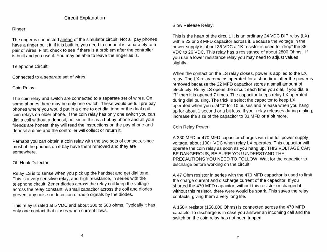
Circuit Explanation
Ringer:
The ringer is connected ahead of the simulator circuit. Not all pay phoneshave a ringer built it, if it is built in, you need to connect is separately to apair of wires. First, check to see if there is a problem after the controlleris built and you use it. You may be able to leave the ringer as is.
Telephone Circuit:
Connected to a separate set of wires.
Coin Relay:
The coin relay and switch are connected to a separate set of wires. Onsome phones there may be only one switch. These would be full pre payphones where you would put in a dime to get dial tone or the dual coilcoin relays on older phone. If the coin relay has only one switch you candial a call without a deposit, but since this is a hobby phone and all yourfriends are honest, they will read the instructions on the pay phone anddeposit a dime and the controller will collect or return it.
Perhaps you can obtain a coin relay with the two sets of contacts, sincemost of the phones on e bay have them removed and they aresomewhere.
Off Hook Detector:
Relay LS is to sense when you pick up the handset and get dial tone.This is a very sensitive relay, and high resistance, in series with thetelephone circuit. Zener diodes across the relay coil keep the voltageacross the relay constant. A small capacitor across the coil and diodesprevent any noise or detection of radio signals by the diodes.
This relay is rated at 5 VDC and about 300 to 500 ohms. Typically it hasonly one contact that closes when current flows.
Slow Release Relay:
This is the heart of the circuit. It is an ordinary 24 VDC DIP relay (LX)with a 22 or 33 MFD capacitor across it. Because the voltage in thepower supply is about 35 VDC a 1K resistor is used to “drop” the 35VDC to 26 VDC. This relay has a resistance of about 2800 Ohms. Ifyou use a lower resistance relay you may need to adjust valuesslightly.
When the contact on the LS relay closes, power is applied to the LXrelay. The LX relay remains operated for a short time after the power isremoved because the 22 MFD capacitor stores a small amount ofelectricity. Relay LS opens the circuit each time you dial, if you dial a“7” then it is opened 7 times. The capacitor keeps relay LX operatedduring dial pulsing. The trick is select the capacitor to keep LXoperated when you dial “0” for 10 pulses and release when you hangup for about 1 second or a bit less. If your relay releases during dialing,increase the size of the capacitor to 33 MFD or a bit more.
Coin Relay Power:
A 330 MFD or 470 MFD capacitor charges with the full power supplyvoltage, about 100+ VDC when relay LX operates. This capacitor willoperate the coin relay as soon as you hang up. THIS VOLTAGE CANBE DANGEROUS, BE SURE YOU UNDERSTAND THEPRECAUTIONS YOU NEED TO FOLLOW. Wait for the capacitor todischarge before working on the circuit.
A 47 Ohm resistor in series with the 470 MFD capacitor is used to limitthe charge current and discharge current of the capacitor. If youshorted the 470 MFD capacitor, without this resistor or charged itwithout this resistor, there were would be spark. This saves the relaycontacts, giving them a very long life.
A 150K resistor (150,000 Ohms) is connected across the 470 MFDcapacitor to discharge is in case you answer an incoming call and theswitch on the coin relay has not been tripped.
6 7