Embed Size (px)
Citation preview

COUNTY OF VENTURA
PUBLIC WORKS AGENCY
ROAD
STANDARDS
APPROVED BY BOARD OF SUPERVISORS
(FOR APPROVAL DATES, SEE REVISION DATE
TABLES AT END OF STANDARDS)
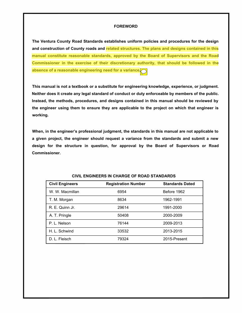
FOREWORD
The Ventura County Road Standards establishes uniform policies and procedures for the design
and construction of County roads and related structures. The plans and designs contained in this
manual constitute reasonable standards, approved by the Board of Supervisors and the Road
Commissioner in the exercise of their discretionary authority, that should be followed in the
absence of a reasonable engineering need for a variance.
This manual is not a textbook or a substitute for engineering knowledge, experience, or judgment.
Neither does it create any legal standard of conduct or duty enforceable by members of the public.
Instead, the methods, procedures, and designs contained in this manual should be reviewed by
the engineer using them to ensure they are applicable to the project on which that engineer is
working.
When, in the engineer’s professional judgment, the standards in this manual are not applicable to
a given project, the engineer should request a variance from the standards and submit a new
design for the structure in question, for approval by the Board of Supervisors or Road
Commissioner.
CIVIL ENGINEERS IN CHARGE OF ROAD STANDARDS
Civil Engineers Registration Number Standards Dated
W. W. Macmillan 6954 Before 1962
T. M. Morgan 8634 1962-1991
R. E. Quinn Jr. 29614 1991-2000
A. T. Pringle 50408 2000-2009
P. L. Nelson 76144 2009-2013
H. L. Schwind 33532 2013-2015
D. L. Fleisch 79324 2015-Present

COUNTY OF VENTURA GUIDE FOR ENGINEERS DEVELOPERS AND CONTRACTORS
The following publications have been adopted by the County for regulating the design and
construction of public improvements constructed by developers; work performed under County or
Watershed Protection District permits; land grading; water systems; and sanitary sewer systems:
1. Ventura County Road Standards (RdStd)
2. Standard Specifications for Public Works Construction (SSPWC).
3. Standard Plans for Public Works Construction (SPPWC).
4. Land Development Manual.
5. Standard Land Development Specifications (SLDS) which adopt supplement and modify SSPWC.
6. State Standard Plans from CALTRANS (SSP).
7. Ventura County Water Works Manual and Sewerage Manual (VCWWM & VCSM).
8. Ventura County Water Works Districts Nos. 1, 16, 17, and 19; Ventura County Service
Areas 29 and 30; and Lake Sherwood Community Services District Rules and Regulations
(R&R).
9. Standard cover sheets for grading
10. Individual project plans and specifications (P&S).
The scope of each publication is contained within that publication. The publications should be used as
follows:
Engineers -Use RdStd, VCWWM and VCSM {also R&R in Districts listed in 5 above) as the general
requirements for design. Do not assume contractors have copies of these publications. If these
standards are to be used for a project place the plates or formulas from these documents in the P&S.
Material in SLDS, SSPWC, SPPWC, and SSP may be referred to in the P&S as contractors may be
assumed to have copies of these publications.
NOTE: The Ventura County Standard Designs are no longer being published and should not
be used as a reference. Use SPPWC in their place. Where SPPWC does not contain an
appropriate design, SSP may be used. If neither have the needed feature, details of the
feature must be shown in the P&S.
NOTE: Construction in Ventura County is also regulated by the California Regional Water
Quality Control Board for the Los Angeles Region under Order R4-2010-0108 and by the
State Water Resources Control Board, Division of Water Quality, by Order 2009-009-DWQ.
Use appropriate Best Management Practices (BMPs) to protect water quality as required and
provided in these orders.
Developers and Contractors -Use SLDS (which adopts and modifies SSPWC); SPPWC and SSP
where specified in the P&S; Grading Cover Sheet and P&S.

FUTURE AMENDMENTS TO THIS MANUAL
Amendments to this manual may be issued from time to time. Users of this publication may contact the
Agency to determine the latest revision date. See the "Revision" pages herein that list the latest date for
each page. The latest version of this manual is available free on the Public Works Agency's web site at:
http://pwaportal.ventura.org/ESD/ESD/StandardsandManuals/docs/roadstds.pdf
If you have questions or comments about this manual please contact:
Agency: Public Works Agency Transportation Department
800 South Victoria Avenue
Ventura, California 93009-1620
Email: [email protected]
Phone: (805) 654-2049

VENTURA COUNTY ROAD STANDARDS INDEX
A-SERIES PLATES - DESIGN AND CONSTRUCTION POLICIES
A-1 DESIGN POLICIES
A-2 GENERAL NOTES
A-3 MATERIAL TESTING
A-4 DRAINAGE
A-5 FOUNDATION & SLOPES
A-6 ASPHALT CONCRETE PAVEMENT DESIGN
A-7 PORTLAND CEMENT CONCRETE PAVEMENT DESIGN
B-SERIES PLATES - ROAD CROSS-SECTION
B-1 SECTION INDEX AND NOTES
B-2 CONTROLLED ACCESS PRIMARY AND SECONDARY ROADS
B-3 SECONDARY FREE ACCESS AND COMMERCIAL AND INDUSTRIAL ROADS
SATICOY AREA - COMMERCIAL / INDUSTRIAL / RESIDENTIAL ROADS
PIRU AREA - URBAN RESIDENTIAL ROADS WITH PARKWAYS
URBAN RESIDENTIAL ROADS
SATICOY AREA - URBAN RESIDENTIAL ROADS WITH PARKWAYS
RURAL ROADS WITHOUT CURBS
B-3S
B-4P
B-5
B-5S B-7
B-8S SATICOY AREA - PRIVATE ROADS/ALLEYS WITH PUBLIC ACCESS
C-SERIES PLATES - SPECIAL RIGHT-OF-WAY REQUIREMENTS
C-2 CUL-DE-SAC TYPE I
C-3 CUL-DE-SAC TYPE II
C-4 CUL-DE-SAC TYPE III
C-5 ROAD INTERSECTION "L" SHAPE
D-SERIES PLATES - INTERSECTIONS AND VERTICAL ALIGNMENT
D-1 VERTICAL CURVES - MINIMUM SIGHT DISTANCE LENGTH
D-5 PRIMARY AND SECONDARY ROADS INTERSECTIONS
D-6 RURAL ROAD INTERSECTIONS
D-7 RESIDENTIAL/COMMERCIAL TRANSITION-PERMANENT CONSTRUCTION
D-9 SIDEWALK TRANSITION AT INTERSECTION
D-10 SIDEWALK WIDENING AT OBSTRUCTIONS
D-11 PRIMARY AND SECONDARY ROAD WITH RURAL ROAD INTERSECTION
D-13 BUS TURNOUT

VENTURA COUNTY ROAD STANDARDS INDEX
E -SERIES PLATES - SIDEWALKS, DRIVEWAYS AND GUTTERS
E-1 CURBS & GUTTERS
E-2
E-2a
E-3
E-4
E-4a
E-6
E-7
E-9
E-11
E-12
E-13
E-14
E-14a
RESIDENTIAL DRIVEWAYS
COMMERCIAL DRIVEWAYS
SIDEWALKS AND SURFACE ACCESS CLOSURES SURVEY MONUMENT
RAISE EXISTING UTILITY COVER
RURAL DRIVEWAY ADT>1000
RURAL DRIVEWAY ADT≤1000
SPEED HUMP/CUSHION
PAVEMENT REPAIR FOR TRENCHING
TRENCH REPAIR DETAIL FOR MORATORIUM ROADS ABOVE GROUND UTILITIES IN ROAD RIGHT-OF-WAY DROP INLET FOR CONCRETE PIPE
DROP INLET FOR CORRUGATED STEEL PIPE
F-SERIES PLATES - TRAFFIC CONTROL AND LIGHTING
F-1 TEMPORARY TERMINATION OF ROAD IMPROVEMENTS
F-3
F-4
F-4a
F-5 F-6
F-9
SIGN POST INSTALLATION
ROAD INTERSECTION NAME SIGN
ROAD INTERSECTION NAME SIGN SPECIFICATIONS ADVANCE ROAD NAME SIGNS
INTERSECTION LIGHTING/LOCATIONROADWAY LIGHTING

1. GENERAL ROAD DESIGN POLICIES
1.1 Scope
All roads which are to be included in the County Road System shall be designed to conform to the
Ventura County Road Standards. Where standards are not definitive, design shall conform to good
engineering practice, and be approved by the Director of Public Works (DPW). The California
Department of Transportation Highway Design Manual (HDM) generally provides guidance in "good
engineering practice" of road design.
1.2 Deviations - Approval Required
Deviations from Right of Way and improvement requirements of the ROAD STANDARDS will be
allowed only with the approval of the Board of Supervisors. Deviations from the technical engineering
requirements of the ROAD STANDARDS may be granted by DPW, or his designee, or by the Board of
Supervisors. Any request for deviation from the requirements of the ROAD STANDARDS shall be
accompanied by sufficient supporting data. This supporting data shall be provided by the individual
requesting the deviation and submitted and approved prior to utilizing the proposed deviation in design.
1.3 Standard Drawings
The DPW may issue, modify, or cancel standard drawings showing engineering and structural details
for road and other construction. Where no standards for an item has been issued by DPW, SPPWC, or
CALTRANS Standard Plans shall be used if the construction feature is covered therein.
1.4 Adjacent to Cities
For areas of the County adjacent to incorporated cities, DPW may require the use of road geometrics
compatible with adjacent city standards.
1.5 Additional Right of Way Required
Turning lanes at intersections, sight distance requirements, drainage improvements, pedestrian
facilities and bicycle lanes, may require Right-of- Way and improvement widths greater than those
shown on the B-series plates.
1.6 Access Policy
The Access Policy adopted by the Board of Supervisors limits the number of lots served by each of the
roadway widths shown on the B-series plates. More restrictive limitations than those shown on the
B-series plates required by the Fire Department and Sheriff for emergency access will govern.
COUNTY OF VENTURA
PUBLIC WORKS AGENCY
ROAD STANDARDS
REVISION: PLATEUS UNITS
DESIGN POLICIES
A-1G
SHEET 1 OF 2

1. GENERAL ROAD DESIGN POLICIES (continued)
1.7 Curve Plates' Basis
The minimum horizontal curve radii provided on the B-series plates are based on a single curve on a
straight grade. Similarly, the minimum vertical curve lengths provided on Plate D-1 are based on a
single curve on a straight alignment. The criteria used in setting these minimums are sight distance and
smooth riding characteristics.
The following design features, within any portion of the road of length equal to the required sight
distance, may result in the reduction of sight distance below the required minimum:
a. More than one horizontal curve,
b. More than one vertical curve,
c. More then one allowed grade break, or
d. A combination of vertical curves, grade breaks and horizontal curves.
When such combination of features are included, the alignment must be investigated and redesigned
as necessary to maintain the sight distance required by the applicable B-Series plate.
1.8 Water Quality and NPDES Requirements
Construction in Ventura County is regulated by the State Water Resources Control Board, Division of
Water Quality and California Regional Water Quality Control Board for the Los Angeles Region under
Permit Number CAS 004002, and/or the most current permit. During construction use site appropriate
Best Management Practices (BMPs) to protect water quality as required and provided in these orders.
COUNTY OF VENTURA
PUBLIC WORKS AGENCY
ROAD STANDARDS
REVISION: PLATEUS UNITS
DESIGN POLICIES
A-1B
SHEET 2 OF 2

2. GENERAL NOTES
2.1 Standard Specifications
All work shall conform to the SLDS
2.2 PCC Pavement
PCC Pavement may be substituted for AC Pavement on all sections when approved by PWA. See
Plate A-7 for design requirements.
When PCC Pavement is used, the PCC Pavement shall extend between intersections. Transition to AC
shall be made at the prolongation of the outer edge of the gutter line of the intersecting road. To
enhance appearance, black pigmented curing compound may be used on PCC Pavement.
2.3 Alternative Materials
Stabilized soil or stabilized aggregate may be used instead of base materials. Test data supporting
equivalency may be required.
COUNTY OF VENTURA
PUBLIC WORKS AGENCY
ROAD STANDARDS
REVISION: PLATEUS UNITS
GENERAL NOTES
A-2H
SHEET 1 OF 2

2. GENERAL NOTES (continued)
2.5 Abbreviations:
AC Asphalt Concrete
BSB Bituminous Stabilized Base
DPW Director of Public Works
CTB Cement Treated Base
LTB Lime Treated Base
PMB Processed Miscellaneous Base
PCC Portland Cement Concrete
SC Soil Cement
SS Select Subbase
PSE Public Service Easement.
AASHTO American Association of State Highway and Transportation Officials
ADA Americans with Disabilities Act
ADT Average Daily Traffic in vehicles per day
E.P. Edge of Pavement
E.S. Edge of Shoulder
HDM "Highway Design Manual", California Department of Transportation
SLDS "Ventura County Standard Land Development Specifications", latest revision
SPPWC "Standard Plans for Public Works Construction", latest edition with all adopted changes
SSP "State Standard Plans", by State of California
Department of Transportation (Caltrans), latest edition
SSPWC "Standard Specifications for Public Works Construction", latest edition, with all adopted
changes
SSS "State Standard Specifications", by State of California, Dept. of Transportation (Caltrans),
latest edition, with all adopted changes
VCSS "Ventura County Standard Specifications"
Other abbreviations are in accordance with SSPWC.
COUNTY OF VENTURA
PUBLIC WORKS AGENCY
ROAD STANDARDS
REVISION: PLATEUS UNITS
GENERAL NOTES
A-2D
SHEET 2 OF 2
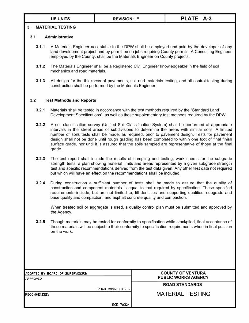
3. MATERIAL TESTING
3.1 Administrative
3.1.1 A Materials Engineer acceptable to the DPW shall be employed and paid by the developer of any
land development project and by permittee on jobs requiring County permits. A Consulting Engineer
employed by the County, shall be the Materials Engineer on County projects.
3.1.2 The Materials Engineer shall be a Registered Civil Engineer knowledgeable in the field of soil
mechanics and road materials.
3.1.3 All design for the thickness of pavements, soil and materials testing, and all control testing during
construction shall be performed by the Materials Engineer.
3.2 Test Methods and Reports
3.2.1 Materials shall be tested in accordance with the test methods required by the "Standard Land
Development Specifications", as well as those supplementary test methods required by the DPW.
3.2.2 A soil classification survey (Unified Soil Classification System) shall be performed at appropriate
intervals in the street areas of subdivisions to determine the areas with similar soils. A limited
number of soils tests shall be made, as required, prior to pavement design. Tests for pavement
design shall not be done until rough grading has been completed to within one foot of final finish
surface grade, nor until it is assured that the soils sampled are representative of those at the final
grade.
3.2.3 The test report shall include the results of sampling and testing, work sheets for the subgrade
strength tests, a plan showing material limits and areas represented by a given subgrade strength
test and specific recommendations derived from the test data given. Any other test data not required
but which will have an effect on the recommendations shall be included.
3.2.4 During construction a sufficient number of tests shall be made to assure that the quality of
construction and component materials is equal to that required by specification. These specified
requirements include, but are not limited to, fill densities and supporting qualities, subgrade and
base quality and compaction, and asphalt concrete quality and compaction.
When treated soil or aggregate is used, a quality control plan must be submitted and approved by
the Agency.
3.2.5 Though materials may be tested for conformity to specification while stockpiled, final acceptance of
these materials will be subject to their conformity to specification requirements when in final position
on the work.
COUNTY OF VENTURA
PUBLIC WORKS AGENCY
ROAD STANDARDS
REVISION: PLATEUS UNITS
MATERIAL TESTING
A-3E

4. DRAINAGE
4.1 Limited Use of Road Section for Drainage
Road cross-sections may be used to convey water originating from adjoining lots and from adjacent
unimproved areas if vehicle and pedestrian use of the road is not unreasonably restricted, and if the
road improvements and adjacent property will not be damaged. Facilities shall be installed to remove
debris from flow from unimproved areas before the flow enters the street. The hydraulic design shall
take into consideration the effect of non-uniform flow at changes in grade, bends and junctions of
multiple streams of water.
4.2 Design Storm Flow
"Storm runoff" used in calculating the capacity of road drainage facilities is that which has a ten percent
probability of occurrence (ten year average return period), provided that the adjacent lot pads shall not
be flooded by the storm runoff which has a one percent probability of occurrence (100 year average
return period). Drainage facilities in sumps may combine side inlet catch basins for the ten percent
flow, and overflow channels for the excess flow. Additionally, flooding caused by clogged drainage
facilities shall be taken into consideration. Culverts and bridges shall be designed to accommodate the
two percent (50 year average return period) storm flow plus 2 feet of freeboard to allow for debris
bulking.
4.3 Urban Roads (Any Section with Curbs)
4.3.1 For the ten percent storm, flow shall be accommodated below the elevation of the top of the curb.
To increase the carrying capacity of roads, the curb height may be increased to 8" and/or the
cross-slope reduced to not less than one percent, provided the algebraic sum of the cross-slope
and the longitudinal slope is equal to or greater than two percent. Design shall insure that curbs
shall not be overtopped when water is carried across the crown.
4.3.2 To prevent pavement erosion damage and danger to pedestrians, the flow (based on a ten percent
storm) carried in a half road section shall not in any case exceed the value given by the formula Q =
125/S where S is the longitudinal slope of the roadway in percent. In no case shall the maximum
value of Q in a half road section exceed 40 cfs.
ADOPTED BY BOARD OF SUPERVISORS:
APPROVED:
RECOMMENDED:
ROAD COMMISSIONER
RCE 79324
COUNTY OF VENTURA
PUBLIC WORKS AGENCY
ROAD STANDARDS
REVISION: PLATEUS UNITS
DRAINAGE
A-4D
SHEET 1 OF 5

4. DRAINAGE (continued)
4.3.3 To prevent road damage caused by drainage water escaping from the road gutters, thorough
engineering consideration shall be given in the design to contributing factors including the quantity
of water, the effects of water carried debris, the effects of non-uniform flow conditions, and the
effect of parked cars.
Such consideration may result in more conservative designs than otherwise provided by the Road
Standards, including any combination of the following:
a. Reduction of the quantity of water allowed to be carried in the road cross-section by the
installation of storm drains and catch basins.
b. Installation of sidewalks in accordance with ADA requirements adjacent to the curbs where
not otherwise required.
c. Installation of deflectors at driveways and other vulnerable locations.
d. Utilization of higher curb faces.
e. Changing cross-slope to 1%.
4.3.4 Designs meeting the following criteria will be presumed to meet the requirements of 4.33:
Approximate 10% Q in Gutter Velocity Depth to Curb Special
½ of road - cf fps Height Ratio Requirements
< 25/S < 6 ≤1.0 None
25/S to 55/S 6 to 8 ≤0.5 None
0.5 to 1.0 [1]
56/S to 125/S 8 to 10 ≤0.4 None
8 to 10 0.4 to 1.0 None
[1] Install deflectors at driveways and diagonally across unpaved parkways adjacent to curbs
with maximum spacing of 200/(S-2) feet.
S is the longitudinal slope of the roadway in percent.
4.3.5 Interference to traffic flow by storm water on primary, secondary, commercial and industrial roads
(Plates B-2 and B-3) shall be minimized by keeping that portion of the roadway designated on
Plates B-2 and B-3 free from longitudinally flowing water during the ten percent storm. No cross
gutters are permitted across primary or secondary roads (Plates B-2, B-3[A], B-3[B], B-3[C]). No
cross gutters are permitted across collector roads (Plates B-5[A] and deleted B-4[A] and B-6[A])
except at locations where vehicular traffic is required to stop or where through traffic movement is
precluded such as at the single leg of a T-intersection.
ADOPTED BY BOARD OF SUPERVISORS:
APPROVED:
RECOMMENDED:
ROAD COMMISSIONER
RCE 79324
COUNTY OF VENTURA
PUBLIC WORKS AGENCY
ROAD STANDARDS
REVISION: PLATEUS UNITS
DRAINAGE
A-4B
SHEET 2 OF 5

4. DRAINAGE (continued)
4.3.6 Minimum gradients required by the B-Series plates are for gutter grades. This may require street
center line grades to be greater than the minimum provided by the B-Series plates where gutters
are not parallel thereto.
4.3.7 Wherever possible, cul-de-sacs shall drain away from the bulb end.
4.4 Rural Roads (Not Curbed)
4.4.1 To carry drainage from the road Right of Way and from overland sheet flows of adjacent property to
the nearest natural drainage way or drainage channel, lined or unlined roadside ditches shall be
provided on each side of the road. A ditch may be omitted when adjacent land drains away from the
road, and road runoff sheet flows over adjacent land without concentrating.
4.4.2 Roadside ditches shall not be used to intercept or divert natural or artificial channels.
4.4.3 For the ten percent storm, water shall be maintained below the elevation of the outer edge of the
shoulder. For the two percent storm, water shall be maintained below the elevation of the edge of
pavement.
4.4.4 Roadside ditches shall have adequate culverts at driveways. The minimum shall be 18" in diameter
or an equivalent flow capacity arch or rectangular section with a minimum inside dimension of 15".
4.4.5 The side slopes of ditches shall be 2:1 or flatter. Design of the ditch shall be such that the velocity
of flow will not erode the ditch. Lining of ditches may be required. Allowable velocities for unlined
ditches shall not exceed the recommended velocities tabulated in the "Ventura County Watershed
Protection Design Manual" (Ventura County Flood Control Design Manual, July, 1968), Section 314.
4.5 Sump Drainage
a. Catch basins at low points of a road (sumps) shall not utilize grate-only inlets.
b. An outlet for drainage shall be provided from sumps, in addition to catch basins designed for
the 10% occurrence storm flow, to insure that the 1% occurrence storm flow will not flood over
lot pads.
ADOPTED BY BOARD OF SUPERVISORS:
APPROVED:
RECOMMENDED:
ROAD COMMISSIONER
RCE 79324
COUNTY OF VENTURA
PUBLIC WORKS AGENCY
ROAD STANDARDS
REVISION: PLATEUS UNITS
DRAINAGE
A-4B
SHEET 3 OF 5
Material/Lining
Maximum
Permissible Mean
Velocity, ft/s
Fine Sand
Coarse Sand
Sandy Silt
Silt Clay
Clay
Gravel
Rock Riprap
Concreted Rock Riprap
Concrete
Proprietary Fabricated Materials
2.0
4.0
2.0
3.5
6.0
6.0
15.0
25.0
40.0
See note below
2
Maximum permissible velocity for a soft-bottom channel shall be
controlled by the invert material.
Maximum permissible velocity for proprietary fabricated materials shall
be based on literature specific to the material and is subject to approval.
1
2

4. DRAINAGE (continued)
4.6 Physical Standards for Drainage Facilities
The California Department of Transportation Highway Design Manual (HDM), Chapter 850, shall be the
criteria for the physical design of drainage facilities in County road rights of way except as otherwise
provided herein. Where drainage facilities within County road rights of way are or will be operated and
maintained by the Ventura County Watershed Protection District, their standards must also be
complied with.
4.6.1 References in the HDM to SSS shall be replaced by appropriate sections of the SLDS. Where
special construction methods are required and SLDS does not provide for such method, special
provisions will be required.
4.6.2 Non-Reinforced Cast-in-Place concrete pipe cannot be used in County roads.
4.6.3 Storm drainage facilities substantially paralleling the road centerline and under the pavement
section shall be one of the following:
- Reinforced concrete pipe (cast-in-place or precast)
- Reinforced concrete box (cast-in-place or precast)
- Ribbed polyvinyl chloride pipe
- Exterior Corrugated/Interior Smooth, High Density Polyethylene Pipe
- Asphalt Lined and Coated Galvanized or Aluminized Corrugated Steel Pipe with smooth
lining of cement or asphalt
4.6.4 Where design flow velocities of drainage facilities exceed 20 fps, adequate protection against
erosion shall be provided in the invert of pipe and lined channels.
4.6.5 Flexible Pipe: Corrugated Steel Pipe, Ribbed PVC-PS46 and HDPE-Exterior Corrugated/Interior
Smooth shall have a minimum cover of 24" measured from top of rigid pavements or the bottom of
flexible pavement base course and shall have a maximum cover of 15' without special approval of
calculation showing adequate strengths at other heights of cover.
4.6.6 Local depressions for catch basins shall not extend into the curb returns at intersections.
They shall not interfere with curb ramps at any location.
4.6.7 Grates for catch basins in the roadway and shoulder must be traffic-load rated and
bicycle safe.
4.7 Lot Drainage
4.7.1 The direct connection of roof drains and roof gutter drains to conduits under sidewalks is prohibited
by the Ventura Countywide Stormwater Quality Management Program.
4.7.2 Drainage from landscaped areas of lots may be directed to the road gutter by properly designed
conduits under sidewalks.
ADOPTED BY BOARD OF SUPERVISORS:
APPROVED:
RECOMMENDED:
ROAD COMMISSIONER
RCE 79324
COUNTY OF VENTURA
PUBLIC WORKS AGENCY
ROAD STANDARDS
REVISION: PLATEUS UNITS
DRAINAGE
A-4D
SHEET 4 OF 5

ADOPTED BY BOARD OF SUPERVISORS:
APPROVED:
RECOMMENDED:
ROAD COMMISSIONER
RCE 79324
COUNTY OF VENTURA
PUBLIC WORKS AGENCY
ROAD STANDARDS
PLATEUS UNITS A-4
REVISION: A
NOTES:
1. This configuration may be used only where there is an existing curb in residential areas. For new
construction use SPPWC Plan 150.
2. Through curb drains may be used only as provided by Plate A-4c (Section 4.7) to drain landscape
areas.
3. Hole through curb must be cored. If curb is damaged, reconstruct per SPPWD Plan 150.
4. If sidewalk is existing, remove a panel by saw-cutting between adjacent construction joints, and replace
per Plate E-3.
5. The direct connection of roof drains and roof gutter drains to conduits under sidewalks is prohibited by
the Ventura Countywide Stormwater Quality Management Program.
2" min.
Trim pipe flush
with curb face
3" schedule
40 PVC pipe
Fill voids around pipe
with epoxy or grout
2% max.
1% min. fall
Property line
Contraction joint
Remove and reconstruct panel
See note 4
Curb
Gutter
A A
SECTION A-A
NOT TO SCALE
Contraction jointThree IOM (#3) bars
24" long, evenly spaced
1 1/2" min.
3" min.
SHEET 5 OF 5
DRAINAGE CURB DRAIN THROUGH
EXISTING CURB

5. ROADWAY FOUNDATION AND SLOPE CRITERIA
5.1 Cross-Section Stability
Roadways shall be located on a stable foundation. The slopes, both uphill and downhill from the
roadway, shall be stable. Slopes outside the road Right of Way lines, shown on "B" series plates as
"2:1 typ", shall be constructed in accordance with the Ventura County Building Code and the Land
Development Manual, Chapters 7 and 8. These requirements may result in slopes other than 2:1.
5.2 Expansive Soils Stabilization
When basement soil R-value is 14 or less, 4" of PMB shall be placed under curbs, gutters and
sidewalks.
COUNTY OF VENTURA
PUBLIC WORKS AGENCY
ROAD STANDARDS
REVISION: PLATEUS UNITS
FOUNDATIONS & SLOPES
A-5E

6. ASPHALT CONCRETE PAVEMENT DESIGN
6.1 General Principles
The design of asphalt concrete pavement is based on the principle of layers of progressively
decreasing strengths from the finished surface to the sub-grade. In each case, the finished surface
consists of a layer of asphalt concrete pavement of the thickness computed by the design formulas, but
not less than a specified minimum thickness.
The design method provides a numerical solution to the thickness of any layer based on the following:
a. The Traffic Index, a measure of the amount and type of truck traffic that is expected over the
20-year period following construction.
b. The physical strength, measured by gravel equivalent, of the layer being designed.
c. The physical strength, measured by R-Value, of the layer immediately below the layer being
designed.
d. The minimum physical strength, measured by R-Value, of the sub-grade material.
e. The thickness and physical strength, measured by gravel equivalent, of the material above the
layer being designed, if any.
By varying the types of materials used, a number of different, acceptable pavements can be designed
for each combination of Traffic Index and sub-grade R-Value.
6.2 Mix Design
C1 or C2-PG 64-10 for Plates B-4, B-5, B-5a and B-8
B-PG 64-10 for Plates B-2, B-3, B-3a and B-7
COUNTY OF VENTURA
PUBLIC WORKS AGENCY
ROAD STANDARDS
REVISION: PLATEUS UNITS
ASPHALT CONCRETEPAVEMENT DESIGN
A-6D
SHEET 1 OF 5
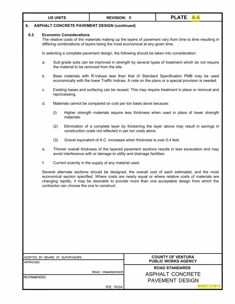
6. ASPHALT CONCRETE PAVEMENT DESIGN (continued)
6.2 Economic Considerations
The relative costs of the materials making up the layers of pavement vary from time to time resulting in
differing combinations of layers being the most economical at any given time.
In selecting a complete pavement design, the following should be taken into consideration:
a. Sub-grade soils can be improved in strength by several types of treatment which do not require
the material to be removed from the site.
b. Base materials with R-Values less than that of Standard Specification PMB may be used
economically with the lower Traffic Indices. A note on the plans or a special provision is needed.
c. Existing bases and surfacing can be reused. This may require treatment in place or removal and
reprocessing.
d. Materials cannot be compared on cost per ton basis alone because:
(l) Higher strength materials require less thickness when used in place of lower strength
materials.
(2) Elimination of a complete layer by thickening the layer above may result in savings in
construction costs not reflected in per ton costs alone.
(3) Gravel equivalent of A.C. increases when thickness is over 0.4 feet.
e. Thinner overall thickness of the layered pavement sections results in less excavation and may
avoid interference with or damage to utility and drainage facilities.
f. Current scarcity in the supply of any material used.
Several alternate sections should be designed, the overall cost of each estimated, and the most
economical section specified. Where costs are nearly equal or where relative costs of materials are
changing rapidly, it may be desirable to provide more than one acceptable design from which the
contractor can choose the one to construct.
COUNTY OF VENTURA
PUBLIC WORKS AGENCY
ROAD STANDARDS
REVISION: PLATEUS UNITS
ASPHALT CONCRETEPAVEMENT DESIGN
A-6B
SHEET 2 OF 5

6. ASPHALT CONCRETE PAVEMENT DESIGN (continued)
6.3 Design Method
6.3.1 Nomenclature
T = Thickness of layer in feet.
TI = Traffic Index from B-series Plates or a greater value indicated by a traffic engineering
study.
GF = Gravel factor of material in a layer.
GE = Gravel equivalent of the pavement or a layer. The theoretical thickness of the pavement
or layer if composed entirely of material with a GF of one.
SF = Safety factor. An additional thickness of A.C. expressed as gravel equivalent.
R = Minimum resistant R-Value of material.
AC = Subscript referring to Asphalt Concrete layer.
B = Subscript referring to Base layer.
SB = Subscript referring to Subbase layer.
SG = Subscript referring to Subgrade.
MIN = Subscript referring to Minimum Allowable Thickness of a layer.
6.3.2 Constants for AC
GF = 2.5 for TI ≤ 5.
GF = 5.67 (TI)½ for TI > 5.
TAC min. over Base material or stabilized subgrade = 0.21 feet.
TAC min. over unstabilized Subgrade = 0.3 feet.
COUNTY OF VENTURA
PUBLIC WORKS AGENCY
ROAD STANDARDS
REVISION: PLATEUS UNITS
ASPHALT CONCRETEPAVEMENT DESIGN
A-6B
SHEET 3 OF 5

6. ASPHALT CONCRETE PAVEMENT DESIGN (continued)
6.3.3 Constants for Bases and Subbase
Material R* GF SFAC** Ft T Min.,Ft.
SS 60 1.0 0.00 0.33 (Subbase only)
PMB 78 1.1 0.16 0.33
LTB 80 *** 0.18 0.50
SC 80 1.2 0.00 0.50
BSB 80 1.3 0.00 0.50
CTB 80 1.2 0.18 0.50
* Maximum R-Value, lesser values must be used if Standard Specifications are modified.
** For TI<8.0, SFAC=0.
*** LTB GF = 0.9 + (Unconfined compressive strength in PSI/1000)
6.3.4 Conventional Design
A layered system of A. C., base and sub-base over the subgrade. The material in each layer must
have a higher R-Value than the material below it. The thickness of each layer is designed, starting
with the A.C. surface layer and working down, as follows:
a. GEAC = 0.0032 x TI x (100 - RB) + SFAC
b. TAC = GEAC/GFAC If TAC <0.21, use TAC = 0.21'
c. GEB = 0.0032 x TI x (100 - RSB) - (TAC x GFAC)
d. TB = GEB/GFB If TB <TMIN, use TB = TMIN
e. GESB = 0.0032 x TI x (100 - RSG) - (TAC x GFAC) - (TB x GFB )
f. TSB = GESB If TSB <TMIN, then either
(l) TSB = TMIN or
(2) TB = (GEB + GESB)/GFB and TSB = 0
COUNTY OF VENTURA
PUBLIC WORKS AGENCY
ROAD STANDARDS
REVISION: PLATEUS UNITS
ASPHALT CONCRETE PAVEMENT DESIGN
A-6B
SHEET 4 OF 5

6. ASPHALT CONCRETE PAVEMENT DESIGN (continued)
6.3.5 Thick Lift Design
An A.C. surface layer, 4" or more in thickness, placed either directly on the subgrade (stabilized* or
unstabilized) or over a layer of base material* designed as follows:
a. GEAC= 0.0032 x TI x (100 - RSG) - TB x GFB
b. T1 = GEAC/GFAC
c. If T1 ≤ 0.4', TAC = T1
d. If T1 > 0.4', T2= [GEAC - (0.4 x GFAC)] / (1.3 x GFAC)
e. If T2 ≤ 0.4', TAC= 0.4' + T2
f. If T2 > 0.4', T3= [GEAC - (0.92 x GFAC)] / (1.5 x GFAC)
g. Then TAC = 0.8' + T3
*Base or stabilized subbase shall be 6" or thicker.
COUNTY OF VENTURA
PUBLIC WORKS AGENCY
ROAD STANDARDS
REVISION: PLATEUS UNITS
ASPHALT CONCRETEPAVEMENT DESIGN
A-6B
SHEET 5 OF 5

7. PORTLAND CEMENT CONCRETE (RIGID) PAVEMENT DESIGN
7.1 Thickness
7.1.1 Rigid (PCC) Section Design shall follow Caltrans HDM Section 620.
Subgrade shall be prepared per SSPWC 301-1.
7.2 Joints & Construction
7.2.1 PCC pavement shall be constructed per SSPWC 302-6 using the PCC class from 7.1 above.
7.2.2 Contact (Construction) joints and weakened plane joints shall be per SPPWC 134. Contact joints
shall be installed around catch basin aprons and manhole slabs.
7.2.3 The joint layout plan shall provide that, in general, joints are spaced so as the slabs between joints
have a maximum dimension of 15 feet and a minimum dimension of 5 feet. To the extent
practicable, longitudinal joints shall coincide with lane lines. See American Concrete Pavement
Association publication "Design and Construction of Joints for Concrete Streets" for good design
practice.
7.3 Concrete Class
Structures (Reinforced) Class 560-C-3250
Pavement Minimum Class 520-A-2500
Curbs, gutters, cross gutters, driveways, and walks Class 520-C-2500
Higher Classes shown on plans or in specifications will govern.
COUNTY OF VENTURA
PUBLIC WORKS AGENCY
ROAD STANDARDS
REVISION: PLATEUS UNITS
PORTLAND CEMENT CONCRETEPAVEMENT DESIGN
A-7F

NOTES APPLICABLE TO ALL B-SERIES PLATES
1. Pavement widths in curbed sections, measured between top inside faces of curbs.
2. Additional right-of-way width or easements may be required for utilities.
The PSE's shown on Plate B-5 shall be offered for dedication.
3. Drainage to be designed in accordance with Plate A-4.
4. Pavement to be designed in accordance with Plate A-6 or A-7.
5. No superelevation where design speed is 40 MPH or less.
6. At intersections of two road types, use curb return radius for type requiring the longer radius.
7. Curbs and gutters, median curbs and cross gutters per Plate E-1. Sidewalks per Plate E-3.
8. Hinge point of slope shall be a minimum of one foot away from sidewalks.
9. Where maximum number of lots served is a criterion, extension of roads; additional divisions of tributary
land, including redivision of lots exceeding two acres in size; and rezoning effects shall be considered.
10. Prime coat may be omitted if all of the following conditions are met:
a) Asphalt layer is placed within two weeks of completion of base course.
b) Traffic is not routed over completed base before paving.
c) Construction is completed during the dry season of May through October.
If construction is performed during the wet season of November through April, prime coat may be omitted
if no rain occurs between completion of base course and paving and the time between completion of
base and paving is reduced to three days.
Where prime coat has been omitted and
(l) rain occurs,
(2) traffic is routed over base course, or
(3) paving is delayed,
measures shall be taken to restore base course, subbase course and subgrade to conditions that will
meet specifications, as directed by the Engineer.
11. Fog seal coat is not required for new construction.
COUNTY OF VENTURA
PUBLIC WORKS AGENCY
ROAD STANDARDS
REVISION: PLATEUS UNITS
SECTION INDEX & NOTES
B-1F
SHEET 1 OF 2

NOTES APPLICABLE TO ALL B-SERIES PLATES (continued)
13. Minimum road gradients shall be as follows:
a) For roads where both gutters are built on cut or not more than two feet of fill:
Land Gradient Minimum Gutter Gradient
>2.5% 1%
2.5% to 1% 0.4 x Land Gradient
<1% 0.4%
b) For roads where either gutter is built on fill more than two feet deep:
Land Gradient Minimum Gutter Gradient
>1.67% 1%
1.67% to 1% 0.6 x Land Gradient
<1% 0.6%
c) Where the end of a new road is not controlled by joining an existing road, or by a major land
form constraint, the designer of the road shall consider minor realignments to avoid road
grades under 1%.
d) For roads using Plate B-7, minimum centerline grades shall be the same as the minimum
gutter grades in "a" above.
e) "Land Gradient" shall mean the natural gradient of the land prior to grading measured along
the general direction of the road.
14. Maximum road gradients for Plate B-5 sections may be increased in hillside areas to the following
maximum:
B5[A] B5[B] B5[C]
Over 200' length 15% 15% 15%
Less than 200' length 15% 20% 25%
15. Above-ground utility in parkways and sidewalks shall be located per SPPWC Standard Plate 101-2.
COUNTY OF VENTURA
PUBLIC WORKS AGENCY
ROAD STANDARDS
REVISION: PLATEUS UNITS
SECTION INDEX & NOTES
B-1D
SHEET 2 OF 2

DESIGN CRITERIA
B-2 [A]
PRIMARY
NOTES:
1. Emergency parking only.
2. Median planter boxes may be required.
3. Median curbs required only adjacent to intersections. Extend through end of left turn pocket and transition.
4. Sidewalks, curb and gutter may be omitted when approved by the road commissioner and the planning director.
5. Provide extra R/W width at intersections for sight distance as detailed on Plate D-5.
6. Superelevated curve radii, superelevation and transitions shall be in accordance with sections 202 & 203 HDM.
B-2 [B]
SECONDARY
Right of way width, R 118' 94'
Pavement width, W 44' 32'
Flooding free width, F 26' 14'
ADT in 20 years, max 36,000 24,000
Flat terrain Mountains
Design speed 60 mph 50 mph
Curve radius, min without superelevation 2400' 1400'
Gradient, min/max (%) (see plate B-1b 1.0/3.0 1.0/5.0
Stopping sight distance 580' 440'
Applies to B-2 [A] & B-2 [B]
Superelevation, max 0.07
Curb return radius, min 35'
Curve length, min/max 500'/2640'
Tangent length between curves, min 400'
Traffic index 8.0
Applies to B-2 [A] & B-2 [B]
R
14'8'
PCC walk,
see note 4
Fog seal
coat2
:
1
2
:
1
1' min
R/W
W 8'W
2
:
1
2
:
1
1' min
SS
PMB
AC
Curb & gutter
Prime coat
Median curb, see note 3
1" ac with sterilant, see note 2
R/W
F no flooding
ADOPTED BY BOARD OF SUPERVISORS:
APPROVED:
RECOMMENDED:
ROAD COMMISSIONER
RCE 79324
COUNTY OF VENTURA
PUBLIC WORKS AGENCY
ROAD STANDARDS
REVISION: PLATEUS UNITS
CONTROLLED ACCESS PRIMARY AND SECONDARY ROADS
B-2K
℄
2%
2% Slope 2% Slope
2%

DESIGN CRITERIA
B-3 [A]
SECONDARY
B-3 [B]
MAJOR
COMM OR IND
B-3 [C]
COMM OR
IND
B-3 [D]
MINOR COMM
OR IND
Right of way width, R 80' 80' 68' 60'
When req'd by Planning Comm. - 96' - -
Pavement width, W 64' 64' 52' 40'
Flooding free width, F 28' 28' 16' 4'
Sidewalk width, S 8' 8' - -
When req'd by Planning Comm. - 8'-16' 8' 10'
Curb return radius 35' 45' 45' 45'
Curve length, max/min 300'/2640' 300'/2640' - -
Tangent length between curves, min 200' 200' - -
Traffic index 7.5 7.5 7.5 7.0
ADT in 20 years (max) >20,000 >16,000 8,000-16,000 <8,000
Design speed 40 mph 40 mph 40 mph 30 mph
Curve radius, min 800' 800' 550' 300'
Gradient, min/max (%) 1.0 / 5.0 1.0 / 5.0 1.0 / 6.0 1.0 /10.0
(see Plate B-1 Notes 3 & 13)
Stopping sight distance 300' 300' 300' 60'
Prime coat
Curb & gutter
SSAC
PMB
Fog seal
coat
F
No flooding
R
2
:
1
W
W/2 W/2 S
2
:
1
1' min
2
:
1
2
:
1
PCC walk,
see note 2
S
1' min
R/W
R/W
NOTES:
1. For B-3 [C], provide extra R/W width at intersections for sight distance as detailed on plate D-5.
2. Sidewalks, curb and gutter may be omitted in rural areas, when approved by the road
commissioner and planning director.
ADOPTED BY BOARD OF SUPERVISORS:
APPROVED:
RECOMMENDED:
ROAD COMMISSIONER
RCE 79324
COUNTY OF VENTURA
PUBLIC WORKS AGENCY
ROAD STANDARDS
PLATEUS UNITS B-3REVISION: J
℄
SECONDARY FREE ACCESSANDCOMMERCIAL AND INDUSTRIAL ROADS
2% Slope 2% Slope
2%2%

DESIGN CRITERIA
Right of way width, R, min
Pavement width, W, min
Parking width, PK
Flooding free width, F
Parkway width, P, min
Sidewalk width, S, min
When req'd by Planning Comm.
Planter / Planting Strip, PL
Curb return radius
Traffic index
ADT in 20 years (max)
Design speed
Curve radius, min
Gradient, min/max (%)
Stopping sight distance
Prime coat
Curb & gutterSS
ACPMB
Fog seal
coat
R
2
:
1
W
W/2 (see note 5) W/2(see note 5)
S
2
:
1
PCC walk,
see note 2
R/W
R/W
NOTES:1. For B-3 [D], provide extra R/W width at intersections for sight distance as detailed on plate D-5.
2. Sidewalks, curb and gutter may be omitted in rural areas, when approved by the road
commissioner and planning director.
3. Mixed parking can be Parallel parking on one side of the road and Angled parking on the other
or Angled parking on both sides of the road. Angled parking will be at 45°.
4. Addition of Class II or III Bike lanes as required per the Saticoy Area General Plans.
5. In the case of mixed parking where W=49', W/2= 20'(w/Par.) and 29' (w/ Ang.)
6. For additional requirements including bike facilities and parking, refer to Saticoy Area Plan.
℄
PK
PL
P
2
:
1
2
:
1
S
PK
PL
P
F
ADOPTED BY BOARD OF SUPERVISORS:
APPROVED:
RECOMMENDED:
ROAD COMMISSIONER
RCE 79324
COUNTY OF VENTURA
PUBLIC WORKS AGENCY
ROAD STANDARDS
REVISION: PLATEUS UNITS B-3SO
SATICOY AREA
COMMERCIAL/INDUSTRIAL/
RESIDENTIAL ROADS
No flooding
2% Slope
2%
2% Slope
2%
(see Plate B-1 Notes 3 & 13)
1'
min
1'
min
B-3 [A]
MINOR COMM
OR RES
64'
40'
8'
12'
12'
12'
10'
-
45'
7.0
8,000
30 mph
300'
1.0 / 10.0
60'
B-3 [D]
COMM OR IND
COLLECTOR
68'
52'
8'
12'
8'
6'
8'
2'
45'
7.5
16,000
40 mph
550'
1.0 /6.0
300'
B-3 [C]
MINOR COMM
OR IND
60'
40'
8'
12'
10'
6'
10'
4'
45'
7.0
8,000
30 mph
300'
1.0 / 10.0
60'
B-3 [B]
MINOR COMM OR
RES W/ MIXED
PARKING³
(see note 3)
71'/80'
49'/58'
8' Par/17' Ang
12'
11'
11'
10'
-
45'
7.0
8,000
30 mph
300'
1.0 / 10.0
60'

Curb & gutter
R
2
:
1
W
W/2 W/2
2
:
1
2
:
1
2
:
1
PCC walk
4'
℄
R/W
R/W
10' 10'
1' min
Right of way width, R 60' 56' 52'
Pavement width, W 40' 36' 32'
Curb return radius 25' 25' 25'
Traffic index, > 200 lots served 6.5 n/a n/a
Traffic index, 141-200 lots served 6.0 n/a n/a
Traffic index, 51-140 lots served 5.5 5.5 n/a
Traffic index, 21-50 lots served 5.0 5.0 5.0
Traffic index, ≤ 20 lots served 4.5 4.5 4.5
Lots served, max - cul-de-sac
Lot size ≤ 0.2 ha (20,000 sf) 170 50 10
Lot size > 0.2 ha (20,000 sf) 200 140 39
Lots served, max (other) 550 140 39
Design speed 30 mph 25 mph 25 mph
Curve radius, min 300' 250' 200'
Gradient, min/max (%) 1.0/12.0 1.0/2.0 1.0/15.0
(see Plate B-1)
Stopping sight distance 200' 160' 160'
Cul-de-sac length max
Lot size ≤ 0.2 ha (20,000 sf) any 800 200
Lot size > 0.2 ha (20,000 sf) any any 200
Loop length, max any 600' 0
DESIGN CRITERIA
B-4 [A]
COLLECTOR
B-4 [B]
MINOR
B-4 [C]
CUL-DE-SAC
REVISION: PLATEUS UNITS
SS
PMB
AC
4'
ADOPTED BY BOARD OF SUPERVISORS:
APPROVED:
RECOMMENDED:
ROAD COMMISSIONER
RCE 79324
COUNTY OF VENTURA
PUBLIC WORKS AGENCY
REVISION: PLATEUS UNITS B-4PO
URBAN RESIDENTAL ROADSWITH PARKWAYS
2%
2% Slope 2% Slope
2%
1' min
ROAD STANDARDS PIRU AREA
NOTE: For Main Street improvements see Piru Area Plan

Curb & gutter,
see note 6
SSAC
PMB
R
2
:
1
W
W/2 W/2
2
:
1
2
:
1
2
:
1
PCC walk,
see note 5
5'
R/W
R/W
6.5'
5' 5'
6.5'
5'
Reqd
PSE
Right of way width, R 53' 49' 45'
Pavement width, W 40' 36' 32'
Curb return radius 25' 25' 25'
Traffic index, > 200 lots served 6.5 n/a n/a
Traffic index, 141-200 lots served 6.0 n/a n/a
Traffic index, 51-140 lots served 5.5 5.5 n/a
Traffic index, 21-50 lots served 5.0 5.0 5.0
Traffic index, ≤ 20 lots served 4.5 4.5 4.5
Lots served, max - cul-de-sac
Lot size ≤ 0.2 ha (20,000 sf) 170 50 10
Lot size ≥ 0.2 ha (20,000 sf) 200 140 39
Lots served, max (loop) 550 100 0
Lots served, max (other) 550 140 39
Design speed 30 mph 25 mph 25 mph
Curve radius, min 300' 250' 200'
Gradient, min/max (%) 1.0 / 12.0 1.0 / 12.0 1.0 / 15.0
(see Plate B-1 Notes 3, 13 & 14)
Stopping sight distance 200' 160' 160'
Cul-de-sac lenght max
Lot size ≤ 0.2 ha (20,000 sf) any 800' 200'
Lot size ≥ 0.2 ha (20,000 sf) any any 200'
Loop lenght, max any 1600' 0
DESIGN CRITERIA
B-5 [A]
COLLECTOR
B-5 [B]
MINOR
B-5 [C]
CUL-DE-SAC
ADOPTED BY BOARD OF SUPERVISORS:
APPROVED:
RECOMMENDED:
ROAD COMMISSIONER
RCE 79324
COUNTY OF VENTURA
PUBLIC WORKS AGENCY
ROAD STANDARDS
REVISION: PLATEUS UNITS
URBAN RESIDENTIAL ROADS
B-5H
℄
Reqd
PSE
1' min
2%
2% Slope2% Slope
2%
1' min
SHEET 1 OF 2

NOTES
1. Changes in R/W and improvements required between Plate B-5 and other plates shall occur only at
intersections, not in midblock.
2. When using the design shown on Plate B-5, the transitions at intersections as shown on Plate D-9 and
the sidewalk widening as shown on Plate D-10 shall be installed.
3. Where the land gradient (Plate B-1b, Section 13.e) is greater than 10%, slopes for Plate B-5 may be
increased to 15% for reaches more than 100' away from intersections.
4. On Loops and Cul-de-sacs in hillside areas, crown may be eliminated and a 2% cross-fall provided, for
the entire width of pavement, toward the cut slope. A Type A-1 curb may be used on the high side.
5. Sidewalk Requirements:
Abutting Lot Size Requirement
1 Acre or smaller PCC Sidewalk
Larger than 1 Acre PCC Sidewalk or
and smaller than 2 Acres alternate approved by Director
2 Acres or larger No sidewalk required. Slope area behind curb up at 4%.
Preapproved alternates are:
a. AC 4" thick, C2-PG 64-10 thickened at driveways per Plate E-1.1.
b. AC 2" thick, C2-PG 64-10 over 4" of PMB. Driveways shall be per Plate E-1.1.
6. Where abutting lots are 2 Acres or larger, standard curb and gutter may be replaced by a rolled curb and
gutter, or by a PCC gutter with sloped paving extending to a height of 6" above the gutter flow line.
Rolled curb and gutter shall be per State Standard Plan A87A, Type E.
ADOPTED BY BOARD OF SUPERVISORS:
APPROVED:
RECOMMENDED:
ROAD COMMISSIONER
RCE 79324
COUNTY OF VENTURA
PUBLIC WORKS AGENCY
ROAD STANDARDS
REVISION: PLATEUS UNITS
URBAN RESIDENTIAL ROADS
B-5H
SHEET 2 OF 2

Curb & gutter
SSAC
PMB
R
2
:
1
W
W/2
2
:
1
PCC walk
R/W
6' min
10' min 5'
Right of way width, R, minPavement width, W, minParking width, PK
Curb return radius
Traffic index, > 200 lots served Traffic index, 141-200 lots served Traffic index, 51-140 lots served Traffic index, 21-50 lots served Traffic index, ≤ 20 lots served Lots served, max - cul-de-sac
Lot size ≤ 0.2 ha (20,000 sf)
Lot size ≥ 0.2 ha (20,000 sf)
Lots served, max (loop)
Lots served, max (other)
Design speed
Curve radius, min
Gradient, min/max (%)
(see Plate B-1 Notes 3, 13 & 14)
Stopping sight distance
Cul-de-sac length max
Lot size ≤ 0.2 ha (20,000 sf)
Lot size ≥ 0.2 ha (20,000 sf)
Loop length, max
DESIGN CRITERIA
ADOPTED BY BOARD OF SUPERVISORS:
APPROVED:
RECOMMENDED:
ROAD COMMISSIONER
RCE 79324
COUNTY OF VENTURA
PUBLIC WORKS AGENCY
REVISION: PLATEUS UNITS
B-5SO
℄Reqd
PSE
2.5'
1.5'
W/2
R/W
6' min
10' min5'
Reqd
PSE
1' MIN
1.5'
2
:
1
2
:
1
PKPK
ROAD STANDARDS SATICOY AREA
URBAN RESIDENTIAL ROADS
WITH PARKWAYS
56'
36'
8'
25'
n/a
n/a
5.5
5.0
4.5
-
50
140
100
140
25 mph
250'
1.0 / 12.0
160'
-
800
any
1600'
2.5'
2% Slope
2%
2% Slope
2%
1' MIN
B-5 [B]
MINOR
NOTE: For additional details see Piru Area Plan

Traffic index 7.0 6.5
ADT in 20 years, max 8000 4000
Design speed 50 mph 40 mph
Curve radius, min
Without superelevation 1375' 550'
With max superelevation 850' n/a
Gradient, min/max (%) 1.0/10.0 1.0/12.0
(see Plate B-1, Notes 3 & 13)
Stopping sight distance 440' 300'
Superelevation, max 0.11 n/a
Prime coat
SS
AC
PMB
60'
40'
16' 16'
2 : 1
Extend PMB & SS
under shoulder
4'
R/W
R/W
10'
5%
10'
Fog seal
coat
2 : 1
4'
ADOPTED BY BOARD OF SUPERVISORS:
APPROVED:
RECOMMENDED:
ROAD COMMISSIONER
RCE 79324
COUNTY OF VENTURA
PUBLIC WORKS AGENCY
ROAD STANDARDS
REVISION: PLATEUS UNITS
RURAL ROADS
WITHOUT CURBS
B-7G
DESIGN CRITERIA
B-7 [A]
COLLECTOR
B-7 [B]
RURAL
℄
2
:
1
2
:
1
2
:
1
2
:
1
2% Slope
5%
2% Slope
1' min1' min

DESIGN CRITERIA
Right of way width, R
Pavement width, W
Parkway width, P
When req'd by Planning Comm.
Curb return radius
Curve lenght, max/min
ADT in 20 years (max)
Design speed
Prime coat
SS
AC
PMB
Fog seal
coat
R
W
W/2
R/W
R/W
ADOPTED BY BOARD OF SUPERVISORS:
APPROVED:
RECOMMENDED:
ROAD COMMISSIONER
RCE 79324
COUNTY OF VENTURA
PUBLIC WORKS AGENCY
REVISION: PLATEUS UNITS B-8SO
℄
B-8 [A]
ONE-WAY
ALLEY
B-8 [B]
TWO-WAY
ALLEY
P
W/2
P 3'
1"
6"
Ribbon gutter
ROAD STANDARDS SATICOY AREA
PRIVATE ROADS / ALLEYS
WITH PUBLIC ACCESS
20'
20'
4'
-
20'
-
n/a
10 mph
20'
20'
-
-
20'
-
n/a
10 mph
2%2%
3/8"
ADOPTED BY BOARD OF SUPERVISORS:
APPROVED:
RECOMMENDED:
ROAD COMMISSIONER
RCE 79324
COUNTY OF VENTURA
PUBLIC WORKS AGENCY
ROAD STANDARDS
REVISION: PLATEUS UNITS
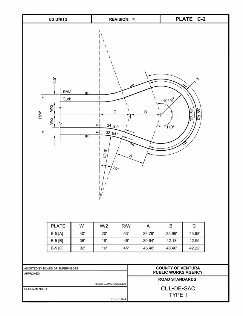
CUL-DE-SACTYPE I
C-2F
C B
PLATE W W/2 R/W A B C
B-5 [A] 40' 20' 53' 33.79' 35.96' 43.68'
B-5 [B] 36' 18' 49' 39.64' 42.18' 42.95'
B-5 [C] 32' 16' 45' 45.48' 48.40' 42.22'
A
32
.6
4
'
34
.9
1
'
2
0
°
9
3
.5
'
110°
110°
4
0
'
6
.
5
'
153
.59
'
178
.55
'
R/W
Curb
W/2
W/2
R/W
6.5
'

ADOPTED BY BOARD OF SUPERVISORS:
APPROVED:
RECOMMENDED:
ROAD COMMISSIONER
RCE 79324
COUNTY OF VENTURA
PUBLIC WORKS AGENCY
ROAD STANDARDS
REVISION: PLATEUS UNITS
CUL-DE-SACTYPE II
C-3F
A
W/2
W/2
R/W
6.5
'
6
.
5
'
1
25
.6
6
'
146
.08
'
Δ
Δ
L
L
L
L
PLATE L L L L
B-5 [A] 23.31' 215.61' 26.17' 185.47'
B-5 [B] 22.40' 219.18' 27.51' 188.55'
B-5 [C] 23.46' 219.18'' 28.81' 191.51'
PLATE W W/2 R/W A Δ
B-5 [A] 40' 20' 53' 50.99' 42° 50' 00"
B-5 [B] 36' 18' 49' 53.06' 45° 02' 08"
B-5 [C] 32' 16' 45' 54.99' 47° 09' 23"
12 3
4
3
1
4
2
28.5'
28.5'
R/W
Curb
4
0
'

ADOPTED BY BOARD OF SUPERVISORS:
APPROVED:
RECOMMENDED:
ROAD COMMISSIONER
RCE 79324
COUNTY OF VENTURA
PUBLIC WORKS AGENCY
ROAD STANDARDS
REVISION: PLATEUS UNITS
CUL-DE-SACTYPE III
C-4E
A
W/2
W/2
R/W
6.5'
Δ & Δ
L
L
4
2
R = 35.0'
R/W
Curb
PLATE L L L L
B-5 [A] 30.93' 196.55' 37.98' 169.07'
B-5 [B] 32.62' 199.31' 40.06' 171.45'
B-5 [C] 34.27' 202.00' 42.09' 173.76'
PLATE W W/2 R/W A Δ & Δ Δ & Δ
B-5 [A] 40' 20' 53' 66.33' 62° 10' 54" 242° 10' 54"
B-5 [B] 36' 18' 49' 68.29' 65° 35' 08" 245° 35' 08"
B-5 [C] 32' 16' 45' 69.97' 68° 53' 59" 248° 53' 39"
1 2 34
1 3 42
6.5'
46.5' = R
4
40.0' = R
2
L
1
L
3
2 4
3
R = 28.5'
1
Δ & Δ
1 3
Diagram above is Type III-R which is preferred.
Mirror image of diagram is Type III-L.

ADOPTED BY BOARD OF SUPERVISORS:
APPROVED:
RECOMMENDED:
ROAD COMMISSIONER
RCE 79324
COUNTY OF VENTURA
PUBLIC WORKS AGENCY
ROAD STANDARDS
REVISION: PLATEUS UNITS
ROAD INTERSECTION"L" SHAPE
C-5A
* Use only where approved by the planning director and the road commissioner.
NOTE: When Δ₁is less than 72°, a smooth
curve with a minimum radius conforming
with the standards for the particular
geometric section shall be used.
PLATE R/W W P R R R R R R R Δ A B
B-3 [A]* 84' 64' 10' 25' 35' 80' 112' 122' 48' 38' 23° 15' 22" 63.17' 13.00'
B-3 [B1]* 84' 64' 10' 35' 45' 80' 112' 122' 48' 38' 11° 06' 46" 30.84' 3.00'
B-3 [B2]* 96' 64' 16' 29' 45' 80' 112' 128' 48' 32' 11° 06' 46" 30.84' 3.00'
B-3 [C] 68' 52' 8' 37' 45' 80' 106' 114' 54' 46' 19° 18' 32" 52.91' 9.00'
B-3 [D] 60' 40' 10' 35' 45' 70' 90' 100' 50' 40' 15° 21' 32" 37.08' 5.00'
B-5 [A] 53' 40' 6.5' 28.5' 35' 60' 80' 86.5' 40' 33.5' 16° 35' 52" 34.28' 5.00'
B-5 [B] 49' 36' 6.5' 28.5' 35' 60' 78' 84.5' 42' 35.5' 19° 40' 00" 40.39' 7.00'
B-5 [D] 45' 32' 6.5' 28.5' 35' 60' 76' 82.5' 44' 37.5' 22° 19' 54" 45.60' 9.00'
2
W
R/W
Curb
R/W
PP
R
3
R
6
R
7
R
1
R
3
R
6
R
7
R
2
R
3
R
4
R
5
See Note
Δ
2
Δ
2
Δ
1
Δ
2
Δ
2
A
B
Δ
1
1 2 3 4 5 76

VERTICAL CURVES - MINIMUM SIGHT DISTANCE LENGTH
ADOPTED BY BOARD OF SUPERVISORS:
APPROVED:
RECOMMENDED:
ROAD COMMISSIONER
RCE 79324
COUNTY OF VENTURA
PUBLIC WORKS AGENCY
ROAD STANDARDS
REVISION: PLATEUS UNITS
VERTICAL CURVES - MINIMUM
SIGHT DISTANCE LENGTH
D-1A
DESIGN SPEED
MPH
SIGHT DIST. FEET
25
150
35
200
40
300
50
430
60
580
Grade Diff.
in %
Cul-de-
sac
S C S C S C S C S C
0.50
1
1.5
2
3
4
5
6
7
8
9
10
11
12
13
14
15
16
17
18
19
20
22
24
26
28
30
32
34
36
38
40
50
10
20
20
30
40
50
60
70
80
90
100
110
120
130
140
150
160
170
180
190
200
210
230
250
270
10
10
10
20
20
90
130
170
190
220
250
270
300
330
350
380
410
430
460
490
510
540
590
650
700
750
810
860
910
970
1020
1070
1340
10
10
10
20
20
30
60
100
140
160
180
200
220
240
260
270
290
310
330
350
370
390
430
470
510
540
580
620
660
700
740
770
970
10
10
10
20
40
130
190
220
260
300
330
370
410
440
480
510
550
590
620
660
700
730
810
880
10
10
10
20
20
70
140
180
220
250
280
310
340
370
400
430
460
490
520
550
580
610
670
730
10
20
20
30
120
240
320
380
440
500
560
630
690
750
810
870
940
1000
1060
1120
1180
1250
1370
1490
10
20
20
30
160
270
340
410
480
550
610
680
750
820
880
950
1020
1090
1160
1220
1290
1360
1490
1630
10
20
30
40
240
400
500
600
700
800
900
1000
1100
1200
1300
1400
1500
1600
1700
1800
1900
2000
2200
2400
10
20
30
220
440
590
730
880
1020
1170
1320
1460
1610
1750
1900
2040
2190
2330
2480
2630
2770
2920
3210
3500
20
30
40
50
360
560
700
840
970
1110
1250
1390
1530
1670
1800
1940
2080
2220
2360
2500
2640
2770
3050
3330
20
30
280
500
760
1020
1270
1520
1780
2030
2280
2530
2790
3040
3290
3550
3800
4050
4300
4560
4810
5060
5570
6080
LEGEND: C=Crest Curves S=Sag Curves; V=Design Speed (MPH)
A=Alegrabraic % Diff in grades; L=Length of Curve
Grade breaks less than 0.5% may be made without a vertical curve at
intervals in feet not less than (5 x A x V).
Vertical curve elevations shall be computed and staked at intervals that
will insure a smooth curve made up of short chords.
Points shall not be further apart in feet than 4 x (L/A) and BVC, Center
& EVC shall always be computed and staked. See HDM for discussion of
good practice in designing vertical curves.
1/2
ADOPTED BY BOARD OF SUPERVISORS:
APPROVED:
RECOMMENDED:
ROAD COMMISSIONER
RCE 79324
COUNTY OF VENTURA
PUBLIC WORKS AGENCY
ROAD STANDARDS
REVISION: PLATEUS UNITS
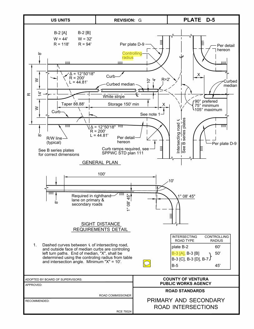
PRIMARY AND SECONDARYROAD INTERSECTIONS
D-5G
10'
4'
White stripe
WW
Curb
Per plate D-9
Per detail
hereon
Curbed median
R
8'
8'
R/W line
(typical)
Curb
R=2'
90° prefered
75° minimum
105° maximum
Storage 150' minX
See note 1
Δ = 12°50'18"
R = 200'
L = 44.81'
Intersecting road ℄
See B
series plates
Curbed
median
Curb ramps required, see
SPPWC STD plan 111
Per detail
hereon
Per plate D-9
Δ = 12°50'18"
R = 200'
L = 44.81'
8'
SIGHT DISTANCEREQUIREMENTS DETAIL
GENERAL PLAN
Required in righthand
lane on primary &
secondary roads
See B series plates
for correct dimensions
1. Dashed curves between ℄ of intersecting road,
and outside face of median curbs are controling
left turn paths. End of median, "X", shall be
determined using the controling radius from table
and intersection angle. MInimum "X" = 10'.
100'
X
14'
1° 08' 45"
1° 08' 45"
INTERSECTING
ROAD TYPE
CONTROLLING
RADIUS
plate B-2 60'
B-3 [A], B-3 [B] 50'
B-3 [C], B-3 [D], B-7
B-5 45'
10'
B-2 [A] B-2 [B]
℄
℄
W = 44' W = 32'
R = 118' R = 94'
Taper 88.88'
Controlling
radius

ADOPTED BY BOARD OF SUPERVISORS:
APPROVED:
RECOMMENDED:
ROAD COMMISSIONER
RCE 79324
COUNTY OF VENTURA
PUBLIC WORKS AGENCY
ROAD STANDARDS
REVISION: PLATEUS UNITS
RURAL ROAD INTERSECTIONS
D-6E
Refer to Plate B-7 for
road design criteria
ɸ = 75° to 105° (90° prefered)
Δ = 180° - ɸ
Δ = 20°
Δ = Δ - 2Δ
Ɵ = 180°- Δ
R = 120'
R = 40'
T = 43.68' +
T
1
2
1
2
T
1
47.70' x sin1/2 Δ
2
sin1/2 Ɵ
T
R=50'
R/W line (typical)
T
Δ
1
Δ
1
R
1
R
1
T
Δ
ɸ
R
2
60'
16' 16' 4'
60'
16
'1
6'
4'
E.P.
E.S.
Ɵ
Δ
2
E.S.
E.P.
℄
℄
ADOPTED BY BOARD OF SUPERVISORS:
APPROVED:
RECOMMENDED:
ROAD COMMISSIONER
RCE 79324
COUNTY OF VENTURA
PUBLIC WORKS AGENCY
ROAD STANDARDS
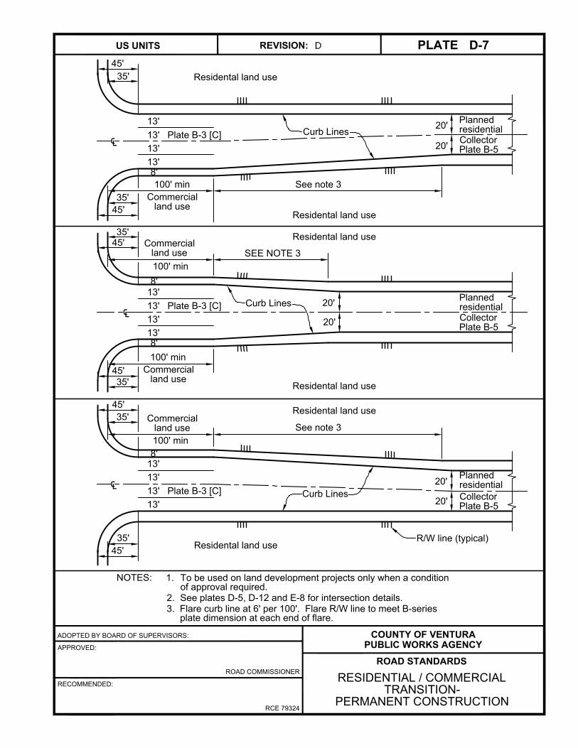
PLATEUS UNITS D-7REVISION: D
RESIDENTIAL / COMMERCIAL
TRANSITION-
PERMANENT CONSTRUCTION
NOTES: 1. To be used on land development projects only when a condition
of approval required.
2. See plates D-5, D-12 and E-8 for intersection details.
3. Flare curb line at 6' per 100'. Flare R/W line to meet B-series
plate dimension at each end of flare.
45'
35'
13'
13' Plate B-3 [C]
13'
13'
45'
35'
Residental land use
100' min
Residental land use
Commercial
land use
Planned
residential
Collector
Plate B-5
See note 3
8'
45'
20'
Commercial
land use
8'
13'
13' Plate B-3 [C]
13'
13'
8'
20'
20'
Planned
residential
Residental land use
Residental land use
SEE NOTE 3
35'
100' min
45'
35'
100' min
Commercial
land use
45'
35'
13'
13' Plate B-3 [C]
13'
13'
45'
35'
Residental land use
Residental land use
Commercial
land use
Planned
residential
See note 3
8'
20'
20'
Curb Lines
100' min
Curb Lines
Curb Lines
R/W line (typical)
20'
℄
℄
℄
Collector
Plate B-5
Collector
Plate B-5

ADOPTED BY BOARD OF SUPERVISORS:
APPROVED:
RECOMMENDED:
ROAD COMMISSIONER
RCE 79324
COUNTY OF VENTURA
PUBLIC WORKS AGENCY
ROAD STANDARDS
REVISION: PLATEUS UNITS
SIDEWALK TRANSITIONAT INTERSECTION
D-9C
1 3
PLATE R R R P A B
B-5
B-2
B-3 [A]
B-3 [B]
B-3 [C] 45' 33' 33' 8' 0.0' n/a
B-3 [D]
B-3 [B]
w/ 16' 45' 29' 29' 16' 0.0' n/a
sidewalk
R/W line
PSE
Sidewalk
Curb
P
BA
Curb ramps
required
20'
20'
R
1
R
2
R
3
1. PSE = public service easement.
2. See SPPWC standard plan 111 for curb ramps.
3. See SPPWC standard plan 112 for curb & sidewalk joints.
Where new construction meets a section with parkways between
sidewalk and the curb, use the transition shown below.
Parkway
Sidewalk
Curb
20'
R
1
R
2
35' 22' 22' 8' 0.0' n/a
2
B-4P 25' 13' 11.5' 5.0' 1.5' 5'
B-3S
B-5S

ADOPTED BY BOARD OF SUPERVISORS:
APPROVED:
RECOMMENDED:
ROAD COMMISSIONER
RCE 79324
COUNTY OF VENTURA
PUBLIC WORKS AGENCY
ROAD STANDARDS
REVISION: PLATEUS UNITS
SIDEWALK WIDENING AT OBSTRUCTIONS
D-10C
1. When plate B-5 improvement configuration is used, provide sidewalk
widening as indicated above at all obstructions.
2. Street lights shall be located behind sidewalk.
3. For obstructions wider than 2' in either direction, special design is
required.
4. Provide block out for mail box installation for each lot. Whenever feasible,
mail boxes for adjacent lots shall be located 2' apart centered on the
common lot line. Mail boxes shall be at least 2' from driveways. where
necessary to avoid driveways or other obstructions, pairs of mail boxes
may be located up to 5' from the common lot line.
5. PSE = public service easement.
R = 15'
5'
R/W
1.5
'
8.5
'
Obstruction
location
PS
E5
'
Curb face
Sidewalk
20
'
9.37' 9.37'
R
=
1
5
'
R
=
15'
2' typ except 1.5'
at mail boxes

ADOPTED BY BOARD OF SUPERVISORS:
APPROVED:
RECOMMENDED:
ROAD COMMISSIONER
RCE 79324
COUNTY OF VENTURA
PUBLIC WORKS AGENCY
ROAD STANDARDS
REVISION: PLATEUS UNITS
PRIMARY AND SECONDARY ROAD WITH RURAL ROAD INTERSECTION
D-11C
Δ = 75° to 105° (90° prefered)
Δ = 20°
Δ = Δ - (2Δ + Δ )
Δ = 5° 08' 34"
Ɵ = 180°- Δ + Δ
R = 120'
R = 32'
T = 43.68' +
T
1
2
39.70' x sin1/2 Δ
2
sin1/2 Ɵ
T
1
2
3
T
1 3
3
Refer to Plate B-2 [A] &
B-2 [B] w/o curbs for
road design criteria
E.P.
Δ
1
R/W line (typical)
E.P.
Refer to Plate B-7 for
road design criteria
Δ
T
FOR USE IN APPROVED
LOCATIONS ONLY
T
℄
℄
1
R
1
Δ
2
R
2
Δ
3
Δ
3
10
0'
CU
RB
ED
M
ED
IA
N
CU
RB
ED
M
ED
IA
N
3'
E.P
.
E.P
.
T
12'
Δ
R
1
Ɵ

ADOPTED BY BOARD OF SUPERVISORS:
APPROVED:
RECOMMENDED:
ROAD COMMISSIONER
RCE 79324
COUNTY OF VENTURA
PUBLIC WORKS AGENCY
ROAD STANDARDS
REVISION: PLATEUS UNITS
BUS TURNOUT
D-13C
L = 40' min L = 50' min* L = 40' min
Edge of PCC - alt 2
Edge of PCC - alt 1
PCC pad
Gutter flow line - alt 1
Gutter flow line - alt 2
2'
Bus shelter
Curb ramp per SPPWC Std Plan
No. 111 if required for access
from an adjacent paved area.
ADA accessibility requirements
apply.
Bus stop sign
W = 10' min
Sidewalk per
B series plates
* For each additional pass through bus berth add 50',
and for each additional layover bus berth add 80'.
NO
PARKING
BUS
STOP
ALTERNATE CROSS-SECTIONS
AC or PCC pavement
8.5' 18" 2'
Alternate Configuration may be
used where road grade is >1%
ALT 2
Standard Configuration
1%-2%
Bus stop sign
No parking sign
8.5' 18" 2'12' through lane
12' through lane
Base
AC or PCC pavement
9" w/o reinforcement
8" with reinforcement
#3 bars at 18" O.C.
Gutter
flow line
18"
1'
Sidewalk
2%
Type A2 curb and gutter
to match adjacent road
sec. cross fall in gutter
modified to match
adjacent slab.
PCC pavement
per plate A-7
2%
Sidewalk
Required
rebar when
PCC
ALT 1
1'
1.5%
Base
2'

1. CONCRETE CURBS & GUTTERS
1.1 Where Required
The requirements for installing curbs and gutters are shown on B-Series plates.
1.2 Design
Curbs and gutters shall be constructed per SPPWC Standard Plan 120, types A1-6 and A2-6. W = 18"
or to match adjacent gutter. Where a sidewalk crosses a driveway the thickness of the sidewalk must
be at least 6 inches.
1.3 PCC Class
Concrete class and construction shall be as specified in Plate A-7. Permeable concrete can be used
for gutters beside an A1-6 curb where a moisture barrier is used to prevent water from infiltrating into
the road base and subgrade under the pavement. The moisture barrier shall be single-ply, 30 mil thick
PVC, and be placed between the edge of pavement and the gutter. It must be a minimum of 5 feet in
depth extending vertically from the top of the permeable concrete gutter. Excess water that cannot
infiltrate must be drained into a storm drain system or a dry well system separated from the roadway.
1.4 Base Required
Where roadway subgrade has an R-value of ≤14, min 4" thickness of PMB shall be placed under curbs
and gutters. Where permeable concrete is used as the gutter place 1 foot of open graded aggregate
wrapped in geotextile filter fabric as the base layer.
2. CROSS GUTTERS
2.1 Where Required
Cross gutters shall be installed wherever surface drainage is to be carried across a road.
2.2 Where Prohibited
No surface drainage is to be carried across a road and no cross gutters are permitted across the
following road sections:
a) Primary or Secondary roads (Plates B-2 & B-3 [A]).
b) Collector roads (Plates B-3 [A], B-4 [A], B-5 [A] and B-7 [A]) except at locations where vehicular
traffic is required to stop or where through traffic movement is precluded such as at the single leg
of a T-intersection.
2.3 Design
Cross gutters shall be constructed per SPPWC Standard Plan 122 and 123.
2.4 PCC Class
Concrete class and construction shall be as specified in Plate A-7.
2.5 Base Required
Cross gutters and spandrels shall be constructed over 6 " thickness of PMB.
COUNTY OF VENTURA
PUBLIC WORKS AGENCY
ROAD STANDARDS
REVISION: PLATEUS UNITS
CURBS & GUTTERS
E-1F

2. DRIVEWAYS
2.1 Residential
Residential driveways shall be constructed according to SPPWC Std. Plan 110, Type A with the
following limitations:
2.1.1 W ≥ 10 feet and W ≤ 27 feet.
2.1.2 The sum of W's for all driveways shall not exceed 40% of the property frontage, however at least
one W = 10' driveway is allowed on each lot.
2.1.3 No driveway shall be constructed in the curb return area at intersections or within 5' of the BCR or
ECR.
2.1.4 No driveway or driveway apron shall be constructed in the area occupied by a catch basin's local
depression.
2.1.5 The outer edge of the driveway warp shall be 2 feet clear of obstructions in the R/W such as fire
hydrants, utility poles, street light standards, signs and mailboxes.
2.1.6 No driveway is allowed unless there is space on the private property for parking an 18' long vehicle.
2.1.7 Where the road grade exceeds 5% and there is no sidewalk next to the curb, an L-shaped deflector
curb shall be installed on the downslope side of the driveway. The curb shall be SPPWC 120, Type
A1-6, 6" high above the roadway curb, extending 5' along the driveway and 2' along the roadway
curb.
2.1.8 PCC may be colored or textured or both. Texturing shall not reduce the required thickness and shall
not be either so smooth or so rough as to be hazardous to pedestrians.
2.1.9 Driveways shall be PCC class 520-C-2500, 6" thick. Where the existing road does not have PCC
curbs, driveways may be constructed of AC C1 or C2-PG 64-10, either 6" thick or 2" thick over 4" of
PMB. Sidewalks over driveway and driveway aprons must be 6' thick.
2.2.0 Where the existing road does not have PCC curbs, driveways shall be constructed at an elevation
compatible with future construction of curbs and gutters.
2.2.1 Minimum distance between outer edges of adjacent driveway slopes:
On same lot ≥ 22'
On adjacent lots ≥ 1'
COUNTY OF VENTURA
PUBLIC WORKS AGENCY
ROAD STANDARDS
REVISION: PLATEUS UNITS
RESIDENTIAL DRIVEWAYS
E-2E

2. DRIVEWAYS (continued)
2.2. Commercial
Commercial driveways shall be constructed according to SPPWC Std. Plan 110, Type A with the
following limitations:
2.2.1 Minimum W = 10 feet.
The sum of all W's shall not exceed 60% of lot frontage.
Lot width Maximum W
< 100' 20'
100' to 150' 30'
> 150' 20% of lot frontage but ≤ 60'
2.2.2 Minimum distance between outer edges of adjacent driveway slopes:
On same lot ≥ 22'
On adjacent lots ≥ 1'
2.2.3 No driveway shall be constructed in the curb return area at intersections or within 5 feet of the BCR
or ECR.
2.2.4 No driveway is allowed where there is any obstacle that prevents any vehicle entering the driveway
from completely clearing the public right of way when parked on the lot.
2.2.5 Driveways shall be PCC class 520-C-2500, 9" thick over 4" of PMB (Rvalue=78). Where the existing
road does not have PCC curbs, driveways may be constructed of AC C1 or C2 PG-64-10, 7 in. thick
or 3" thick over 8" of PMB.
2.2.6 The outer edge of the driveway warp shall be 5' clear of obstructions in the R/W such as fire
hydrants, utility poles street light standards, signs and mailboxes.
2.2.7 Where the road grade exceeds 5% and there is no sidewalk next to the curb, a L-shaped deflector
curb shall be installed on the downslope side of the driveway. The curb shall be SPPWC 120, Type
A1-6, 6" high above the roadway curb, extending 5 feet along the driveway and 2 feet along the
roadway curb.
2.2.8 Where the existing road does not have PCC curbs, when requested by the County, driveways shall
be constructed at an elevation compatible with future construction of curbs and gutters.
COUNTY OF VENTURA
PUBLIC WORKS AGENCY
ROAD STANDARDS
REVISION: PLATEUS UNITS
COMMERCIAL DRIVEWAYS
E-2aB

3. SIDEWALKS
The requirements for installing sidewalks are shown on B-Series plates.
3.1 Design & Construction
3.1.1 Sidewalks shall be constructed per SPPWC Standard Plan 112.
3.1.2 Sidewalks shall be constructed of PCC, 4 inches thick. At driveways, sidewalks shall meet the
requirements.
3.1.3 Where roadway subgrade has a R-value ≤14, 4 inches of PMB shall be placed under the sidewalks
shall meet the requirements of Plates E-2 and E-2a.
3.1.4 Concrete class and construction shall be as specified in Plate A-7.
3.2 Curb Ramps
Curb ramps, as required by the Americans With Disabilities Act and state law, shall be installed at all
intersections. Construction shall be per SPPWC Standard Plan 111-5, Case A. Sidewalks, sidewalk
flares at intersections and rights of way widths may have to be increased to accommodate ramp
design.
4. SURFACE ACCESS TO UNDERGROUND FACILITIES (MANHOLES, etc.):
All surface accesses to underground facilities located within a sidewalk, side path or a marked or
unmarked (Vehicle Code 275) crosswalk area of a roadway, shall meet the following requirements:
1 Covers shall support a load of 500 lbs. applied to a 1 in. diameter area at any location on the
cover. The deflection, when so loaded, shall not exceed 1% of the longest dimension of the
cover. There shall be no residual deflection after the load is removed. Plastic covers shall be
ultraviolet resistant. Covers located in roadways, driveways or other locations to which vehicles
have access, shall be designed for traffic loading.
2 No variation in the surface of the access closure shall exceed 1/8" from the surrounding
surface.
3 No opening in the access closure shall exceed 1/2 in. in width nor 2 1/2" in length. Circular
openings shall not exceed 3/4 in. in diameter.
4 Hold down fastenings shall be flush with the surface of the access closure.
5 The exposed surface of the access closure shall have a permanent slip resistant surface.
6 The resultant finished access closure, as installed, shall not result in a significant variation in
the sidewalk, side path or crosswalk surface that will cause a hazard to pedestrian use.
COUNTY OF VENTURA
PUBLIC WORKS AGENCY
ROAD STANDARDS
REVISION: PLATEUS UNITS
SIDEWALKS ANDSURFACE ACCESS CLOSURES
E-3F

NOTES:
1. Frame is Alhambra Foundry cast iron monument handhole frame with bituminous paint, Plate No. A-2925-F.
2. Cover is Alhambra Foundry cast iron monument handhole cover with bituminous paint, Plate No. A-2925-A.
marked "VENTURA COUNTY SURVEYOR" See Top of Cover Detail above.
3. 8" x 6" IPS class 125 PVC fabricated reducing slip coupling 9/32" wall thickness, colored white
4. Install concrete collar around utility structure, concrete shall be Class 560-C-3250 with maximum 3 inch
slump.
SURVEY MONUMENT
ADOPTED BY BOARD OF SUPERVISORS:
APPROVED:
RECOMMENDED:
ROAD COMMISSIONER
RCE 79324
COUNTY OF VENTURA
PUBLIC WORKS AGENCY
ROAD STANDARDS
REVISION: PLATEUS UNITS
SURVEY MONUMENT
E-4F
TOP OF COVER DETAIL
Cover to be embossed with
special lettering as shown
V
EN T U R
A
CO U N T Y
S U R V E Y O R
3/4"
1/2"
Cast letters
raised 1/8"
Concrete collar
8" x 6" reducing PVC
slip coupling white only.
See note 3.
Finish pavement surface
M10 (#3) rebar, 18" long.
Rebar shall not contact the
survey marker nor protrude
past the concrete.
This area well compacted when
setting monument in sand.
Compact sand by flooding
with water.
Survey marker
Cast iron frame and cover.
See notes 1 and 2.
15" min.
±15"
2'-6"
±3'-9"
560-C-3250 concrete
poured in place
6"
1"
1 1/2" AC min. in AC pvmt.
Ex. pvmt. thickness + 1"
plus ex. base & subbase
thickness (if any)
6"

NOTES:
1. All necessary portions of the subgrade base and pavement shall be neatly removed. Utility cover shall be
raised and the utility riser top sections set to be backfilled to within 1 1/2 inch of the final grade with portland
cement concrete. The remaining 1 1/2 inch shall be backfilled with an asphalt concrete wearing surface
mixture to match the project surface course. The material shall be placed and compacted in a workmanlike
manner to conform to the appearance of the surrounding pavement.
2. Install concrete collar around utility structure, concrete shall be Class 560-C-3250 with maximum 3 inch slump.
3. Asphalt concrete shall be C2-PG 64-10, placed in accordance with Section 302-5.8 of the SSPWC.
4. Backfill compaction shall be a minimum of 95% prior to placing concrete collar.
5. Existing utility installations that do not meet standards must be constructed in compliance with current
standard.
Pavement existing
grade
Raise existing frame
and cover flush to
grade
Pavement finish
grade
6" Min.
See note 2
8" Concrete
See note 2
Adjust riser top section
See note 1 & 5
1 1/2" AC
See note 3
8" min, see
General Note
New overlay
Thickness varies
GENERAL NOTE:
Contractor to expose
existing utility structure to
determine condition and
replace as needed.
Existing riser pipe
Existing riser pipe base
ADOPTED BY BOARD OF SUPERVISORS:
APPROVED:
RECOMMENDED:
ROAD COMMISSIONER
RCE 79324
COUNTY OF VENTURA
PUBLIC WORKS AGENCY
ROAD STANDARDS
REVISION: PLATEUS UNITS
RAISE EXISTING UTILITY COVER
E-4aO
PROPOSED CONDITIONEXISTING CONDITION
New sub-grade base
See note 4

NOTES:
1. The total sum of all driveway widths (exclusive of radii) shall be limited to 20% of property frontage, at least
one 27' driveway will be allowed on each lot.
2. Minimum distances between outer edge of driveways approaches shall be 28' on the same property.
3. Approved locations will generally include areas of a rural nature where curbs are not installed and where
curb installation in the future is unlikely and where the ADT is greater that 1,000.
4. Base under driveway may be omitted where natural ground has adequate structural strength on approval of
the engineer.
5. Design of pipe per Road Standards Plate A-4 Section 4.4 and 4.6.
6. The outer edge of driveway shall be a minimum 2' clear of all vertical obstructions.
ADOPTED BY BOARD OF SUPERVISORS:
APPROVED:
RECOMMENDED:
ROAD COMMISSIONER
RCE 79324
COUNTY OF VENTURA
PUBLIC WORKS AGENCY
ROAD STANDARDS
REVISION: PLATEUS UNITS
RURAL DRIVEWAYADT > 1,000
E-6D
Varies
2" min. AC
4" min. PMB
±
5
%
M
a
x.
Min. 24" for CMP
Alternate
flow line
See note 5
℄Driveway surfacing and profile on
private property per owners
specifications. Recommended
slopes ±12% max.
SECTION X-X
X
X
Alternate flow lines
pipe size to be
determined by
engineer
FOR USE IN APPROVED
LOCATIONS ONLY
PLAN
R=25'
37.5' 21.05'
21.05' 37.5'
80°
8'
R/W
R/W
E.S.
E.S.
E.P.
Varies
Varies
Varies
Varies
Varies
Varies2'
℄
Varies
2" min. AC
4" min. PMB
Alternate
flow line
R/W
℄ R/W
TYPE A
TYPE B
10' min.
27' max.
Driveway
℄ ℄

NOTES:
1. The total sum of all driveway widths (exclusive of radii) shall be limited to 20% of property frontage, at least
one 27' driveway will be allowed on each lot.
2. Minimum distances between outer edge of driveways approaches shall be 28' on the same property.
3. Approved locations will generally include areas of a rural nature where curbs are not installed and where
curb installation in the future is unlikely and where the ADT is greater that 1,000.
4. Base under driveway may be omitted where natural ground has adequate structural strength on approval of
the engineer.
5. Design of pipe per Road Standards Plate A-4 Section 4.4 and 4.6.
6. The outer edge of driveway shall be a minimum 2' clear of all vertical obstructions.
ADOPTED BY BOARD OF SUPERVISORS:
APPROVED:
RECOMMENDED:
ROAD COMMISSIONER
RCE 79324
COUNTY OF VENTURA
PUBLIC WORKS AGENCY
ROAD STANDARDS
REVISION: PLATEUS UNITS
RURAL DRIVEWAYADT < 1,000
E-7D
Varies
2" min. AC
4" min. PMB
±
5
%
M
a
x.
Min. 24" for CMP
Alternate
flow line
See note 5
℄Driveway surfacing and profile on
private property per owners
specifications. Recommended
slopes ±12% max.
SECTION X-X
X
X
Alternate flow lines pipe
size to be determined
by engineer
FOR USE IN APPROVED
LOCATIONS ONLY
PLAN
Varies
R/W
R/W
E.S.
E.S.
E.P.
Varies
Varies
Varies
℄
Varies
2" min. AC
4" min. PMB
Alternate
flow line
R/W
℄ R/W
TYPE A
TYPE B
10' min.
27' max.
Driveway
℄
R=25'
All driveway and drainage construction
must be within the property owned by the
permittee or within the road right-of-way

NOTES:
1. Speed humps may be installed only if approved by the Road Commissioner or his designee.
2. A warning sign stating "Speed Hump" (W17-1) shall be placed at the approach to the first hump. Signs shall
be of high intensity sheeting (30"x30"). Co-mount a W13-1 "10 MPH" (24"x24") warning sign per
CALTRANS standards.
ADOPTED BY BOARD OF SUPERVISORS:
APPROVED:
RECOMMENDED:
ROAD COMMISSIONER
RCE 79324
COUNTY OF VENTURA
PUBLIC WORKS AGENCY
REVISION: PLATEUS UNITS
ROAD STANDARDS
SPEED HUMP/CUSHION
E-9B
SECTION B-B
PLAN
Face of curb
E.P.
A
HU
MP
HU
MP
WIT
H C
UR
BW
IT
HO
UT
C
UR
B
12"
Center of
travel lane
Type "L" marker
± 50' 8'
2'
6'
± 50'8'
2'
BB
Center of speed hump
Reflective white
pavement legend
(thermo plastic) per
CALTRANS
Standard Plan A24E
SECTION A-A
A
24"
24"
Taper
24"
Taper
℄
℄
E.P
.
℄
12'-0"
6'-0"
18" Typ.
2.50"
2.29"
1.68"
0.67"
0.0"
12" white markings
SHEET 1 OF 4
SPEED HUMP

NOTES:
1. Speed cushions may be installed only if approved by the Road Commissioner or his designee.
2. A warning sign stating "Speed Hump" (W17-1) shall be placed at the approach to the first cushion. Signs
shall be of high intensity sheeting (30"x30"). Co-mount a W13-1 "10 MPH" (24"x24") warning sign per
CALTRANS standards.
3. For two-lane roads with a traveled way width of 24' or less, use the design shown above while omitting the
two outer speed cushions.
ADOPTED BY BOARD OF SUPERVISORS:
APPROVED:
RECOMMENDED:
ROAD COMMISSIONER
RCE 79324
COUNTY OF VENTURA
PUBLIC WORKS AGENCY
ROAD STANDARDS
REVISION: PLATEUS UNITS
SPEED HUMP/CUSHION
E-9A
PLAN
Face of curb
HU
MP
WIT
HO
UT
C
UR
B
HU
MP
8'
WIT
H C
UR
B
± 50'
2'
± 50'
2'
Reflective white
pavement legend
(thermo plastic) per
CALTRANS
Standard Plan A24E
SECTION C-C
E.P.
C
C
24"
3'
E.P
.
℄
B* See Section B-B on
Speed Hump Road Standard
Plate E-9
12"
Center of
travel lane
Type "L" marker
8'
B*
Center of
speed cushion
3'
6.5'
3'
℄
B*
3'
4.5'
1.0' typ.
6.5' 3'
2.5"
12" white markings
3'
SHEET 2 OF 4
SPEED CUSHION

ADOPTED BY BOARD OF SUPERVISORS:
APPROVED:
RECOMMENDED:
ROAD COMMISSIONER
RCE 79324
COUNTY OF VENTURA
PUBLIC WORKS AGENCY
ROAD STANDARDS
REVISION: PLATEUS UNITS
SPEED HUMP/CUSHION WARRANTS
E-9O
WARRANTS FOR SPEED HUMPS / CUSHIONS
1. The road must be either a residential road or a local road defined as follows:
a. A residential road, or "residence district," as defined in California Vehicle Code Section 515
is that portion of a highway and the property contiguous thereto, other than a business
district, (a) upon one side of which highway, within a distance of a quarter of a mile, the
contiguous property fronting thereon is occupied by 13 or more separate dwelling houses
or business structures, or (b) upon both sides of which highway, collectively, within a
distance of a quarter of a mile, the contiguous property fronting thereon is occupied by 16
or more separate dwelling houses or business structures. A residence district may be
longer than one-quarter of a mile if the above ratio of separate dwelling houses or business
structures to the length of the highway exists. The "residence district" determination must
be consistent with California Vehicle Code Section 240.
Buildings must be located within 75 feet of the roadway curb face or edge of pavement and
they must face and gain access from the road, to be considered as "fronting" on the road.
b. A local road is defined for the purpose of this guideline as a road intended primarily to
provide direct access to abutting residential buildings. Residential buildings Include
separate dwelling houses, apartment buildings, or multiple dwelling houses.
2. The speed limit on the road must be 25 miles per hour or less, established in accordance with State
law or Board of Supervisors' action.
3. A speed survey must show that 67 percent of the motorists exceed the 25- miles-per-hour speed limit.
4. The road must have a paved width of 40 feet or less and no more than two traffic lanes.
5. The average traffic volume must be greater than 1,000 vehicles in a 24-hour period.
6. No speed hump/cushion may be installed on any street where the Road Commissioner or his
designee determines it cannot be safely installed due to:
a. Severe horizontal or vertical curves
b. Inadequate sight distance to the humps/cushions
c. Excessive street downgrades
7. No speed hump/cushion may be installed on any street where the Road Commissioner or his designee
determines it will create equal or greater traffic problems by causing traffic diversion to a nearby
residential or local road..
SHEET 3 OF 4

ADOPTED BY BOARD OF SUPERVISORS:
APPROVED:
RECOMMENDED:
ROAD COMMISSIONER
RCE 79324
COUNTY OF VENTURA
PUBLIC WORKS AGENCY
ROAD STANDARDS
REVISION: PLATEUS UNITS
SPEED HUMP/CUSHION INSTALLATION POLICY
E-9O
SPEED HUMP/CUSHION INSTALLATION POLICY
1. Speed humps/cushions will be installed only:
• If the location meets the warrants established by the Board of Supervisors.
• Upon receipt of the required petition or when the Road Commissioner or his designee
initiates the proposal
-and-
• The Board of Supervisors or the Road Commissioner or his designee approves the
request
-and-
• In conformance with the standard design in effect at the time of installation.
A petition for installation of speed humps/cushions must be signed by a minimum of 67% of the
property owners on the street or the portion of the street affected concurring in the proposed
installation. The petition must contain language to the effect that, if the petition is approved, the
petitioners must deposit with the Public Works Agency funds in the estimated amount of the cost of
installation of the speed humps/cushions before work will be authorized.
2. Since speed humps/cushions are located in the travelway, additions, alterations, or removals of any or
all speed humps/cushions may be directed at any time.
3. Prior to the approval of new speed humps/cushions on any street, the County Traffic Engineer must
request concurrence from the Ventura County Fire Protection District, the Sheriff's Department, and the
California Highway Patrol within 20 calendar days.
4. Speed-hump/cushion construction costs must be paid by the property owners who sign the required
petition. If the Road Commissioner or his designee originates a proposal and the property owners
concur, construction costs will be paid by the County.
5. The Transportation Department will reassess the speed-hump/cushion program and report to the Board
of Supervisors at approximately five-year intervals. Critical program issues that require Board action
prior to the five-year review will be scheduled for policy guidance.
SHEET 4 OF 4

ADOPTED BY BOARD OF SUPERVISORS:
APPROVED:
RECOMMENDED:
ROAD COMMISSIONER
RCE 79324
COUNTY OF VENTURA
PUBLIC WORKS AGENCY
ROAD STANDARDS
REVISION: PLATEUS UNITS
PAVEMENT REPAIRS FORTRENCHING
E-11B
Cold Mill / Grind Pavement
12" min. outside of top of trench.
Include all damaged pavement.
Asphalt thickness shall be 1.5" min.
See note 6
Existing base
Backfill Zone
Trench backfill slurry
Class 60-E-0.7 (100-E-100)
See note 4
Bedding Zone
Granular material
See note 3
36"
min.
Pipe Bedding
1/4" of pipe O.D. 3" min.
12"
Color Coded Plastic Tape
Where required
1" min.
Existing finish
Surface
AC Base Layer
See note 7
Trench width
Trench width
each side
of pipe at spring line
6" min., 12" max.
Top of trench width
Existing Asphalt
A.C. Base Layer
see note 7
SHEET 1 OF 2

ADOPTED BY BOARD OF SUPERVISORS:
APPROVED:
RECOMMENDED:
ROAD COMMISSIONER
RCE 79324
COUNTY OF VENTURA
PUBLIC WORKS AGENCY
ROAD STANDARDS
REVISION: PLATEUS UNITS
PAVEMENT REPAIRS FORTRENCHING
E-11B
PLATE E-11 NOTES:
1. Construction shall conform to Standard Specifications for Public Works Construction (SSPWC)
except as noted.
2. Trench width shall be as shown unless otherwise shown on the approved plans.
3. Bedding material shall be granular with 100% passing 3/4" sieve, 90 to 100% passing the 3/8" sieve
and not more than 4% passing No. 200 sieve.
4. Backfill between the bedding zone and subgrade shall be Trench Backfill Slurry Class 60-E-0.7
(100-E-100). The Director of Public Works may approve the substitution of one of the following:
a. Controlled Low Strength Material (SSPWC 201-6), provided that laboratory control is
provided to insure compliance with the specifications.
b. Non-cementitious backfill, provided that the backfill is tested and certified to meet the
approved specifications for the material by an independent testing laboratory (SSPWC
217-2). A Quality Control Plan shall be submitted for approval.
5. Compaction shall not use flooding, ponding or jetting unless directed by Soils Engrineer.
6. A.C. Overlay shall be C1 or C2 PG 64-10, 1.5" minimum.
7. AC Base Layer
a. Where existing pavement surface is AC the AC Base Layer thickness shall be equal to or
greater than the existing AC thickness plus 1" with a minimum of 3" and a maximum of 8".
For roads where Traffic Index is 7.0 or greater (Plates B-2, B-3 & B-7a), the AC Base layer
thickness shall be 4" min.
b. Where existing pavement surface is PCC pavement, saw cut 2" into the existing pavement
at the outer edge of the trench and break the remaining thickness. Replace the PCC and
base to the same depth as the existing pavement. The PCC shall be 560-C-3250.
SHEET 2 OF 2

OUTSIDE OF TRAVEL LANE OVER HALF OF ROAD WAY
WITHIN TRAVEL LANE
LEGEND:
Trench Area
Area to be cold mill and pave 1 1/2" min thickness.
ADOPTED BY BOARD OF SUPERVISORS:
APPROVED:
RECOMMENDED:
ROAD COMMISSIONER
RCE 79324
COUNTY OF VENTURA
PUBLIC WORKS AGENCY
ROAD STANDARDS
REVISION: PLATEUS UNITS
PAVEMENT REPAIR FOR TRENCHING
ON MORATORIUM ROADS
E-12O
℄ ℄
℄
Full
road width
Half
road width
1' min.
typ.
1' min.
typ.
3' max.4' max.
SKEWED TRENCH ACROSS ROAD
℄
Full
road width
1' min.
typ.
OVER BOTH TRAVEL LANES
℄
Full
road width
1' min.
typ.
℄1' min.
typ.
1' min.
typ.
WITHIN BULB OF
CUL-DE-SAC
Edge of pavement
- Greater than one half inch (1/2") in thickness within the last five years
- Half inch (1/2") or less in thickness, within the last 3 years, excluding slurry seal
MORATORIUM ROAD: a county roadway that has received a pavement treatment as follows:

1. ABOVE GROUND UTILITY EQUIPMENT
1.1 Where required
It is the preference of the County of Ventura that all equipment and structures for utility company
facilities be placed underground when located within the road right-of-way, or be located outside of the
road right-of-way. However, the County recognizes undergrounding is not always operationally or
economically practical and, therefore, establishes the following policy for the placement of poles,
equipment, and structures above ground.
1.2 Categories
For the purpose of these policies, equipment will be broken into two categories, “small” and “large.”
Small equipment is defined as being less than 24" in height and less than 24" by 36" in area. Large
equipment is defined as all others. Equipment must be located as close to the right of way boundary as
possible.
1.3 Design
1.3.1 Where curb, gutter, and/or sidewalk exists, all above-ground small equipment or poles, when
located in the road right-of-way, shall be located per SPPWC standard plan 101-2.
1.3.2 Where no curb, gutter, and/or sidewalk exists, poles, equipment, and accessory structures
must meet the minimum setback of ten (10) feet from the edge of pavement where feasible. No
above-ground equipment may be placed within five feet of edge of pavement.
1.4 Exceptions
Exceptions, waivers, or variances to these policies may be granted on a case-by-case basis with
review and approval by the Road Commissioner or his authorized representative.
ADOPTED BY BOARD OF SUPERVISORS:
APPROVED:
RECOMMENDED:
ROAD COMMISSIONER
RCE 79324
COUNTY OF VENTURA
PUBLIC WORKS AGENCY
ROAD STANDARDS
REVISION: PLATEUS UNITS
ABOVE GROUND UTILITIESIN ROAD RIGHT-OF-WAY
E-13O

ADOPTED BY BOARD OF SUPERVISORS:
APPROVED:
RECOMMENDED:
ROAD COMMISSIONER
EXPIRES 06-30-16
RCE 33532
COUNTY OF VENTURA
PUBLIC WORKS AGENCY
ROAD STANDARDS
REVISION: PLATEUS UNITS
DROP INLET FORCONCRETE PIPE
E-14O
2
:
1
7'
3'
(typ)
Ac pavement
5%
Debris cage manhole
cover per detail
hereon
7'
F/L
Manhole
Inlet
3.5' 3.5' 3'
2
:
1
Construct manhole cover
per detail hereon
6"
Concrete
(520-C-2500)
Inside of
manhole frame
3/8" steel plate
3/8" steel angles
Verify fit into
manghole frame
before welding
Weld angles to plate
hot dip galvanize
cage after fabrication
Alhambra A-1215
manhole frame
30"
24"
Place 3" PCC
(520-C-2500)
or AC
3/8" steel angles
A A
PLAN
SECTION A-A
MANHOLE COVER DETAIL
Manhole
Inlet
12
"

ADOPTED BY BOARD OF SUPERVISORS:
APPROVED:
RECOMMENDED:
ROAD COMMISSIONER
EXPIRES 06-30-16
RCE 33532
COUNTY OF VENTURA
PUBLIC WORKS AGENCY
ROAD STANDARDS
REVISION: PLATEUS UNITS
DROP INLET FORCORRUGATED STEEL PIPE
E-14aO
CSP
Bearing plate
3/8" Ø U-bolt with (2)
nuts and 1/4" thick
bearing plate (all galv.)
#6 galv. bars 2'-6" long
(4 required), connect to
CSP without bonding
to concrete
6"
3'
(typ)
Ac pavement
DETAIL "A"
30" Ø, 3/8" thick galv. plate
See detail "A"
hereon
5%
2
:
1
2
:
1
12"
6"
3.5' 3.5'3'
7'
7'
A A
PLAN
SECTION A-A
#6 galv. bars 2'-6"
long (4 required)
connect to CSP
per Detail "A"
3/8" filllet welds (typ)
galv. after fabrication
24" CSP, 12 GA,
bit. coated
#6 galv. bar hoop

ADOPTED BY BOARD OF SUPERVISORS:
APPROVED:
RECOMMENDED:
ROAD COMMISSIONER
RCE 79324
COUNTY OF VENTURA
PUBLIC WORKS AGENCY
ROAD STANDARDS
REVISION: PLATEUS UNITS
TEMPORARY TERMINATIONOF ROAD IMPROVEMENTS
F-1E
Current construction
END
Install a 4" high chain link fence from R/W
line to R/W line, with one W31 (END) sign
and four Type N-2 (RED) object markers.
Signs to comply with California Manual on
Uniform Traffic Control Devices, fence to
comply with subsection 304-3 of the
Standard Land Development Specifications.
The W31 (END) sign shall be 30"x30" and
mounted on a 4"x4" redwood post.
R/W
R/W
Future const.
Existing road
Future construction
Widened road
Existing road
E.P.
2X
X
5'25'
Future const.
Type "L"
guide marker
Typ. Type "L" guide markers
at 10' spacing
10'

ADOPTED BY BOARD OF SUPERVISORS:
APPROVED:
RECOMMENDED:
ROAD COMMISSIONER
RCE 79324
COUNTY OF VENTURA
PUBLIC WORKS AGENCY
ROAD STANDARDS
REVISION: PLATEUS UNITS
SIGN POST INSTALLATION
F-3O
Sign
Sign
SIGN INSTALLATION
In dirt area
SIGN INSTALLATION
In sidewalk area
7'
26"
4"
1/4"x8" Spike
2 1/4" 12 ga galvanized
square steel sleeve
Breakaway pin
Existing surface
Post w/knockout holes.
Knock-out only holes
that are to be used
Existing surface
Breakaway pin
Post w/knockout holes.
Knock-out only holes
that are to be used
2" 12 ga galvanized
square steel tubing
Backfill voids with an approved
quick setting cement to full depth
2 1/4" 12 ga galvanized
square steel sleeve
6" Ø
core drill
26"
7'
4"
NOTE:
No concrete is required for sign
posts installed in dirt areas.
Maintain 7" clearance to bottom of
lowest sign.
2" 12 ga galvanized
square steel tubing

ADOPTED BY BOARD OF SUPERVISORS:
APPROVED:
RECOMMENDED:
ROAD COMMISSIONER
RCE 79324
COUNTY OF VENTURA
PUBLIC WORKS AGENCY
ROAD STANDARDS
REVISION: PLATEUS UNITS
ROAD INTERSECTIONNAME SIGN
F-4F
TYPICAL LOCATION
N
A
M
E
A
V
E
Breakaway pin
6" Ø core drill
see Plate F-3
26"
2 1/4" 12 ga
galvanized
square steel
sleeve
Main Rd.
Cro
ss
R
d.
Sid
e R
d.
Sid
e R
d.
Sign Sign
SignSign
BCR
Curb
5'
2'
Sign
Initial
Hwy Type Speed Limit Uppercase Lowercase
Multi-lane + 40 mph 8 inches 6 inches
Multi-lane 40 mph or less 6 inches 4.5 inches
2-lane All speed limits 6 inches 4.5 inches
2-lane 25 mph or less 4 inches* 3 inches*
2" 12 ga galvanized
square steel tubing
Post w/knockout holes.
Knock-out only holes
that are to be used
Slope top away from post
TABLE A
*May be used on two-lane local roads

ADOPTED BY BOARD OF SUPERVISORS:
APPROVED:
RECOMMENDED:
ROAD COMMISSIONER
RCE 79324
COUNTY OF VENTURA
PUBLIC WORKS AGENCY
ROAD STANDARDS
REVISION: PLATEUS UNITS
ROAD INTERSECTION NAME SIGN SPECIFICATIONS
F-4aF
DESIGN: Signs shall consist of two double face signs and have a positive locking device which will keep the
signs mounted at right angles. The road name shall appear on the sign as shown on the official Record Map.
MATERIAL: Signs shall be commercially available signs meeting the State of California Department of
Transportation (CALTRANS) specifications and the California Manual on Uniform Traffic Control Devices. Signs
and fittings shall be made of aluminum, anodized or processed, to prevent corrosion.
FINISH: Signs shall have retroreflective high intensity sheeting applied per CALTRANS and CAMUTCD
specifications. Background to be green, letters and numerals to be white.
LETTERING: Road name letter height shall be as shown in Table A, Plate F-4. The letter style shall conform to
the CAMUTCD.
GUARANTEE: All road signs shall be guaranteed for seven years against chalking and/or fading due to normal
atmospheric corrosion.
SPECIFICATIONS
PRIVATE ROAD NAME SIGNS
ROAD NAME
PRIVATE
Where a private road intersecting a county road is designed in accordance with Plate D-5 or D-6, a private road
name sign may be installed on the same post with a county road name sign.
In all other cases, the private road name sign shall not be within the road right-of-way.

ADOPTED BY BOARD OF SUPERVISORS:
APPROVED:
RECOMMENDED:
ROAD COMMISSIONER
RCE 79324
COUNTY OF VENTURA
PUBLIC WORKS AGENCY
ROAD STANDARDS
REVISION: PLATEUS UNITS
ADVANCE ROAD NAME SIGNS
F-4bD
R
o
a
d
N
a
m
e
26"
2 1/4" 12 ga galvanized
square steel tubing with
knock-out holes
7'
Arrow required at
"T" intersection only
DESIGN: Signs shall consist of one single face sign with cross road name and arrow, if applicable.
MATERIAL: Signs shall be manufactured by applying high intensity reflective sheeting and letters to sheet
aluminum in conformance with CALTRANS and CAMUTCD specifications. A list of manufactures whose signs
meets State specifications will be maintained by the Public Works Agency. Aluminum nuts, bolts, and washers
may be substituted for galvanized hardware.
FINISH: Signs shall have retroreflective high intensity sheeting finish per CALTRANS and CAMUTCD
specifications. Background to be green, letters and numerals to be white.
LETTERING: Road name letters shall be per Table A on Plate F-4. Letters and border spacing shall conform to
CALTRANS and CAMUTCD specifications.
LOCATION: Advance road name signs shall be installed on all primary and secondary roads approximately
300' in advance of all cross intersections. Signs shall be placed in conformance with CAMUTCD. On free
access secondary roads, signs to be installed only when required as a condition of approval.
See Plate F-3 for
sign post installation

ADOPTED BY BOARD OF SUPERVISORS:
APPROVED:
RECOMMENDED:
ROAD COMMISSIONER
RCE 79324
COUNTY OF VENTURA
PUBLIC WORKS AGENCY
ROAD STANDARDS
REVISION: PLATEUS UNITS
INTERSECTION LIGHTING/LOCATION
F-6B
Plate B-2
Sections
Pla
te
B
-2
Se
ctio
ns
Primary to Primary
Primary to Secondary
(Controlled)
Secondary (Controlled) to
Secondary (Controlled)
Plate B-2
Sections
Pla
te
B
-3
Se
ctio
ns
Plate B-3
Sections
Pla
te
B
-3
Se
ctio
ns
Secondary (Controlled) to
Secondary (Free)
Primary to Secondary (Free)
Secondary (Free) to
Secondary (Free)
SHEET 1 OF 2

ADOPTED BY BOARD OF SUPERVISORS:
APPROVED:
RECOMMENDED:
ROAD COMMISSIONER
RCE 79324
COUNTY OF VENTURA
PUBLIC WORKS AGENCY
ROAD STANDARDS
REVISION: PLATEUS UNITS
INTERSECTION LIGHTING/LOCATION
F-6B
R=35'
10'
4.5'
R=25'
2.5'
2'
SHEET 2 OF 2

ADOPTED BY BOARD OF SUPERVISORS:
APPROVED:
RECOMMENDED:
ROAD COMMISSIONER
RCE 79324
COUNTY OF VENTURA
PUBLIC WORKS AGENCY
ROAD STANDARDS
REVISION: PLATEUS UNITS
ROADWAY LIGHTING
F-9D
ROADWAY LIGHTING, WHEN REQUIRED, SHALL CONFORM TO THE FOLLOWING TABLE:
PLATE NO. ROAD CLASS LUMEN SPACING
B-2 [A] Primary Controlled Access
Commercial 22000 200'-250' both sides of median
Residential 16000 200'-250' both sides of median
B-2 [B] Secondary Controlled Access
Commercial 22000 200'-250' both sides of median
Residential 16000 200'-250' both sides of median
B-3 [A] Secondary Free Access and nonconforming roads with more than two lanes of traffic
Commercial 22000 200'-250' staggered both sides
Residential 5800 180'-240' staggered both sides
B-3 [B] Industrial & Commercial 22000 200'-250'
B-3 [C] Industrial & Commercial 22000 200'-250'
B-3 [D] Industrial & Commercial low traffic 5800 @Intersections only
B-5 [A] Collector
Commercial 22000 200'-250' both sides
Residential 5800 180'-240'
B-5 [B] Residential- Minor 5800 180'-240'
B-5 [C] Residential-Loop & Cul-de-Sac 5800 180'-240'
B-7 [A] Rural Road and non-conforming roads with less than 60' of R/W
22000 @Intersections only
B-7 [B] Rural collector and Non-conforming roads with 60' or greater R/W and two lanes of traffic
22000 @intersections only
NOTES:
1. Only Caltrans approved Light-Emitting Diode (LED) Luminaires shall be used.
2. Public works director may modify these requirements.
3. Intersection lighting shall be as shown on Plates F-6 & F-7.
4. Glare shields may be required when their need is indicated. Glare shields are required within the
bounds of the Ojai Valley Area Plan.
5. These spacing requirements are for straight level roads. Winding roads and steep (>5%) or hilly
roads may require add additional lighting.
6. Mounting shall be 25'-28' for 5800 Lumen lights and 28'-32' for 16000 and 22000 Lumen lights.

ROAD STANDARDS - Revision Dates
Plate Original Rev. A Rev. B Rev. C Rev. D Rev. E Rev. F Rev. G Rev. H
02/06/62 03/26/68 06/12/73 03/04/75 04/15/80 12/16/97 03/14/00 11/08/16
02/19/91
01/27/98 03/14/00 11/08/16
02/06/62 03/26/68 06/12/73 04/15/80 01/05/82 01/28/86 02/19/91 03/14/00 11/08/16
04/15/80 02/19/91 12/16/97 03/14/00 11/08/16
02/06/62 03/26/68 06/12/73 04/15/80 03/14/00 11/08/16
02/19/91
04/15/80 03/14/00
Deleted
02/06/62 03/26/68 04/15/80 03/14/00 11/08/16
04/15/80 03/14/00 11/08/16
02/19/91
04/15/80 03/14/00 11/08/16
04/15/80 11/10/81 01/28/91 03/14/00 11/08/16
02/19/91
11/10/81 09/27/83 12/09/86 05/12/87 05/09/89 03/14/00
text
Deleted
03/14/00 11/08/16
curb
12/09/86 05/09/89 03/14/00
Deleted
02/06/62 03/26/68 04/15/80 01/28/86 03/14/00 11/08/16
02/06/62 03/26/68 04/15/80 03/14/00 11/08/16
04/15/80 03/14/00 11/08/16
04/15/80 03/14/00 11/08/16
04/15/80 03/14/00 11/08/16
04/15/80 03/14/00 11/08/16
02/06/62 03/26/68 06/12/73 04/15/80 12/16/97 03/14/00 11/08/16
Deleted
*There are two revisions with the same letter designation.
**When A-4 (curb drain) was added, it was marked original.
The dates shown their effective periods of application.
Numbering of plates with the same basic number has verified with different editions of these Standards, i.e.
"A-4.3", "A-4c", and "A-4C" all refer to the same plate. The 1999 revisions have standardized the numbering
system in the style "A-4a".
A-5
A-6
A-6a
A-6b
A-6c
A-6d
A-7
A-4b
A-4c
A-4d
A-4d
A-4e
A-1a
A-2
A-2a
A-3
A-3a
A-4
A-4a
drain
A-1
Page 1 of 4 Pages

02/06/62 03/01/66 03/26/68 06/12/73 04/15/80 02/19/91 03/14/00 11/08/16
04/15/80 07/19/83 01/28/86 02/19/91 12/16/97 03/14/00 11/08/16
01/28/86 02/19/91 12/16/97 03/14/00 11/08/16
02/06/62 03/01/66 06/12/73 04/15/80 07/19/83 01/28/86 12/09/86 02/19/91*
Deleted
02/06/62 03/01/66 06/12/73 04/15/80 10/21/80 07/19/83 01/28/86 12/09/86*
03/01/66 03/26/68 06/12/73 04/15/80
Deleted
03/01/66 03/26/68 06/12/73 04/15/80
03/26/68 06/12/73 04/15/80
03/26/68 06/12/73 04/15/80
03/26/68 06/12/73 04/15/80
10/03/78 04/15/80
Page 2 of 4 Pages
ROAD STANDARDS - Revision Dates
Plate Original Rev. A Rev. B Rev. C Rev. D Rev. E Rev. F Rev. G
B-1
Plate Rev. H Rev. I Rev. J Rev. K
B-1a
B-1b
B-2 02/06/62 03/01/66 03/26/68 06/12/73 04/15/80 07/19/83 01/28/86 12/09/86*
B-3
B-3S 11/08/16
B-4P 11/08/16
B-4 02/06/62 03/01/66 06/12/73 04/15/80 07/19/83 01/28/86 02/19/91
B-5 02/06/62 03/01/66 06/12/73 04/15/80 07/19/83 01/28/86 02/19/91 03/14/00*
B-5S 11/08/16
B-6
B-7
B-8
B-8S
02/06/62 03/01/66 06/12/73 04/15/80 01/28/86 12/09/86 03/14/00 11/08/16
03/01/66 03/26/68 06/12/73 04/15/80
Deleted
11/08/16
B-9
B-10
B-11
B-12
B-13
B-14
Deleted
Deleted
Deleted
Deleted
Deleted
B-2
B-3
02/19/91 03/14/00 03/20/01 11/08/16
03/14/00 03/20/01 11/08/16
B-5 11/08/16
02/19/91
Deleted
B-6
* To be continued below
Deleted

ROAD STANDARDS - Revision Dates
Plate Original Rev. A Rev. B Rev. C Rev. D Rev. E Rev. F Rev. G
C-1 02/06/62 03/26/68 09/27/83
Deleted
C-2 02/06/62 03/26/68 03/01/83 01/28/86 02/19/91 03/14/00 11/08/16
C-3 02/06/62 03/26/68 06/12/73 03/01/83 02/19/91 03/14/00 11/08/16
C-4 02/06/62 03/26/68 03/01/83 02/19/91 03/14/00 11/08/16
03/14/00 11/08/16
02/06/62 03/01/66 06/12/73 12/09/86 12/16/97 03/14/00 11/08/16
03/14/00*
03/14/00 11/08/16
02/06/62 03/26/68 02/19/91
Deleted
03/01/66 02/19/91
Deleted
03/01/66 02/19/91
Deleted
03/01/66 03/26/68 06/12/73 09/27/83 03/14/00 03/20/01 12/17/02 11/08/16
03/26/68 06/12/73 04/15/80 09/27/83 03/14/00 11/08/16
03/26/68 09/27/83 02/19/91 03/14/00 11/08/16
06/12/73 03/14/00
10/03/78 09/27/83 03/14/00 11/08/16
10/03/78 04/15/00 03/14/00 11/08/16
04/15/00 09/27/83 03/14/00 11/08/16
09/27/83 03/14/00
01/28/86 05/20/86 03/14/00 11/08/16
*D-1 Rev. E was marked as Rev. D until corrected 06/19/01
C-5
D-1
D-1a
D-2
D-3
D-4
Deleted
D-5
D-6
D-7
D-8
D-9
D-10
D-11
D-12
D-13
02/06/62 03/26/68 06/12/73 12/16/97 03/14/00 11/08/16
12/16/97 03/14/00 11/08/16
02/06/62 03/26/68 06/12/73 11/16/82 12/16/97 03/14/00 11/08/16
02/06/62 03/26/68 06/12/73 04/15/80 12/16/97 03/14/00 11/08/16
02/06/62 03/26/68 06/12/73 03/04/75 10/03/78 01/28/86 12/16/97
Deleted
02/06/62 06/12/73 03/14/00 12/17/02 11/08/16
02/06/62 06/12/73 03/14/00 03/20/01 11/08/16
12/23/74 09/27/83 12/16/97
Deleted
E-1
E-1a
02/06/62 03/26/68 06/12/73 01/28/86 12/16/97 03/14/00 11/08/16
01/28/86 12/16/97
Deleted
E-2
E-2a
E-3
E-4
E-4a
E-5
E-6
11/08/16
E-7
E-8
Deleted
Deleted
Page 3 of 4 Pages

02/06/62 06/12/73 04/12/77 02/09/82 03/14/00 11/08/16 02/06/62 03/26/68 06/12/73
02/06/62 06/12/73
Deleted
Page 4 of 4 Pages
ROAD STANDARDS - Revision Dates
Plate Original Rev. A Rev. B Rev. C Rev. D Rev. E Rev. F Rev. G
E-12 02/06/62 03/26/68 09/27/83
Deleted
E-12 11/08/16
E-13 11/08/16
E-14 11/08/16
11/08/16 E-14a
F-1
F-2
F-3
F-3 11/08/16
02/06/62 03/26/68 06/12/73 11/16/82 03/14/00 12/17/02 11/08/16F-4
F-4a 02/06/62 03/26/68 06/12/73 11/16/82 03/14/00 12/17/02 11/08/16
Deleted
02/06/62 06/12/73
F-6 03/26/68 03/14/00 11/08/16F-7 03/26/68 03/14/00 11/08/16
F-8 02/06/62 06/12/73 11/16/82 03/14/00 11/08/16
MOVED AS
F-9 04/01/69 none 02/19/91 03/14/00 11/08/16F-10
04/01/69 02/19/91
F-5
Deleted
Deleted
F-4b
06/19/01 11/12/13 11/08/16E-9
E-10a
E-10b
07/17/02 06/21/05 11/08/16
E-11
07/17/02 06/21/05 11/08/16
11/12/13 11/08/16
E-11 11/08/16