Embed Size (px)
Citation preview

1. Introduction
The demand for cleaner steels increases every year. Inaddition to lowering non-metallic oxide inclusions and con-trolling their size distribution, morphology, and composi-tion, clean steel requires control of sulfur, phosphorus, hy-drogen, nitrogen and even carbon,1,2) and minimizing metal-lic impurity elements such as As, Sn, Sb, Se, Cu, Zn, Pb,Cd, Te and Bi.3) These requirements vary with steel gradeand its end use, as shown in Table 1.4–12) Thus, clean steelfor one application is often unacceptable for a different ap-plication.3)
Metallic impurity elements, which are traditionally foundonly in trace amounts, are becoming an increasing problemdue to their accumulation in the scrap supply. These ele-ments cause intergranular segregation leading to cracks,detrimental precipitates and other problems, which areoften manifested as slivers in the final product. These ele-ments can be difficult to remove in steelmaking and refin-ing, but can be lowered by carefully controlling the scrapcharge, or by charging blast furnace iron, direct-reducediron, or other relatively pure iron source. These trace ele-ment aspects of cleanliness are reviewed elsewhere,3,13–15)
so the remainder of this paper reviews oxide inclusioncleanliness, focusing on Low Carbon Al-Killed steel
(LCAK steel).Inclusions can generate many defects in the steel prod-
uct. For example, LCAK steel cans suffer from crackedflanges due to lack of formability, while axels and bearingssuffer fatigue life problems. Both formability and fatiguelife are highly affected by sulfide and oxide inclusions inthe steel.1) Sliver defects occur as lines along the steel stripsurface parallel to the rolling direction. Slivers plagueLCAK steel sheet for automotive applications, causing bothcosmetic surface imperfections and formability problems.They usually consist of aluminates originating from deoxi-dation or from complex non-metallic inclusions from en-trained mold slag, as documented in many studies, such asat Inland Steel,16) National Steel,17) and Kawasaki Steel.18)
In addition to the amount of inclusions, steel cleanlinessdepends greatly on the size distribution, morphology andcomposition of non-metallic inclusions in the steel. The in-clusion size distribution is particularly important, becauselarge macroinclusions are the most harmful to mechanicalproperties. One kg of typical LCAK steel contains 107–109
inclusions,3) including only 400 80–130 mm inclusions, ten130–200 mm inclusions and less than one 200–270 mmsized inclusion.19) Obviously, detecting the rare large inclu-sions is very difficult. Though the large inclusions are faroutnumbered by the small ones, their total volume fraction
ISIJ International, Vol. 43 (2003), No. 3, pp. 271–291
271 © 2003 ISIJ
Review
State of the Art in Evaluation and Control of Steel Cleanliness
Lifeng ZHANG and Brian G. THOMAS
Department of Mechanical & Industrial Engineering, University of Illinois, Urbana, IL 61801 USA. E-mail: [email protected],[email protected]
(Received on June 11, 2002; accepted in final form on November 7, 2002 )
This paper first reviews the current “state-of-the-art” in the evaluation of steel cleanliness, discussingover 20 different methods. The demand for cleaner steels requires lowering non-metallic oxide inclusionsand also controlling their morphology, composition and size distribution. Because no single method canmeasure all of these aspects accurately, it is best to combine several methods together to quantify steelcleanliness in a given operation. Owing to the cost, time requirements, and sampling difficulties, steelcleanliness is widely inferred using total oxygen, nitrogen pick-up, and other indirect methods. Recentcleanliness values using these indicators are summarized for LCAK at many steel plants around the world.Secondly, this paper reviews operating practices to improve steel cleanliness at the ladle, tundish and con-tinuous caster, emphasizing findings quantified with plant measurements. Inclusions come from manysources, including deoxidation, reoxidation, slag entrapment, refractory wear, and chemical reactions. Theygenerate many defects such as cracks and slivers in the steel product. Steel cleanliness is controlled by at-tention to a wide range of important operating conditions throughout the steelmaking and casting process-es. For ladle operations, FeO and MnO in the slag, ladle treatments, and inclusion modification are dis-cussed. For tundish operations, tundish depth and capacity, casting transitions, refractory lining, tundishflux; gas stirring, and flow controls are discussed. Important transfer operations from ladle to tundish andfrom tundish to mold, such as argon protection, sealing issues, and SEN clogging are summarized. Casteroperations reviewed include the effect of casting speed, fluid flow pattern control, surface level control, andcaster curvature.
KEY WORDS: steel cleanliness; inclusions; total oxygen; nitrogen pick-up; ladle; tundish; mold; caster; plantmeasurement.

may be larger.20) Sometimes a catastrophic defect is causedby just a single large inclusion in a whole steel heat. Thus,clean steel involves not only controlling the mean inclusioncontent in the steel but also on avoiding inclusions largerthan the critical size harmful to the product. To this end,many products in Table 1 include restrictions on the maxi-mum inclusion size. The importance of inclusion size dis-tribution is further illustrated in Fig. 1, which shows themeasured content of inclusions larger than 30 mm to dropfrom 1.61 ppm in a ladle to only 0.58 ppm in the tundish.21)
Thus, the tundish steel is cleaner, despite having a slightlyhigher total oxygen content and more total inclusions.
Non-metallic inclusions come from many sources:17,22–26)
1) Deoxidation products, such as alumina inclusionscause the majority of indigenous inclusions in LCAKsteel. They are generated by the reaction between thedissolved oxygen and the added deoxidant, such as alu-minum. Alumina inclusions are dendritic when formedin a high oxygen environment, as pictured in Figs. 2(a)and 2(b),27) or may result from the collision of smallerparticles, including some of those in Fig. 2(c).28)
2) Reoxidation products, such as alumina, are generatedwhen i) the Al remaining in the liquid steel is oxidizedby FeO, MnO, SiO2 and other oxides in the slag and re-fractory linings, or ii) by exposure to the atmosphere;
3) Slag entrapment, when metallurgical fluxes are en-trained in the steel, occurs especially during transferbetween steelmaking vessels. This forms liquid inclu-sions that are usually spherical, as shown in Fig.2(d).28)
4) Exogenous inclusions from other sources, includeloose dirt, broken refractory brickwork and ceramiclining particles. They are generally large and irregular-shaped. They may act as sites for heterogeneous nucle-ation of alumina and might include the central particlepictured in Fig. 2(c).28)
5) Chemical reactions, for example produce oxides frominclusion modification when Ca treatment is improper-ly performed.29,30) Identifying the source is not alwayseasy, as for example, inclusions containing CaO may
ISIJ International, Vol. 43 (2003), No. 3
© 2003 ISIJ 272
Table 1. Typical steel cleanliness requirements reported for various steel grades.
Fig. 1. Al2O3 inclusion size distribution in ladle and tundish.21)
Fig. 2. Typical inclusions morphology and compositions.

also originate from entrained slag.29)
Steel cleanliness is controlled by a wide range of operat-ing practices throughout the steelmaking processes. Theseinclude the time and location of deoxidant and alloy addi-tions, the extent and sequence of secondary metallurgytreatments, stirring and transfer operations, shrouding sys-tems, tundish geometry and practices, the absorption capac-ity of the various metallurgical fluxes, and casting practices.Steel cleanliness is an important topic that has receivedmuch attention in the literature. An extensive review onclean steel by Kiessling in 1980 summarized inclusion andtrace element control and evaluation methods, especiallyfor ingots.3) More recent reviews of this topic have beenmade by Mu and Holappa31) and by Cramb7) which addedextensive thermodynamic considerations. McPherson andMcLean reviewed non-metallic inclusions in continuouslycasting steel, focusing on the inclusion types (oxides, sul-fides, oxysulfides, nitrides and carbonitrides), inclusion distributions and methods to detect inclusions in thisprocess.32)
This paper reviews the current “state-of-the-art” in steelcleanliness. First, the methods for evaluating steel cleanli-ness are reviewed. Indirect measures, such as total oxygen(T.O.) and nitrogen pick-up, are used to summarize steelcleanliness for LCAK at many steel plants around theworld. Next, operating practices to improve steel cleanli-ness at the ladle, tundish and continuous caster and duringtransfer operations are reviewed. Industrial measurementson steel cleanliness are used to illustrate every point. Thispaper aims to provide useful information for the productionof clean steel, focusing on the control of alumina inclu-sions.
2. Methods to Evaluate Steel Cleanliness
In order to study and control steel cleanliness, it is criti-cal to have accurate methods for its evaluation. Theamount, size distribution, shape and composition of inclu-sions should be measured at all stages in steel production.Measurement techniques range from direct methods, whichare accurate but costly, to indirect methods, which are fastand inexpensive, but are only reliable as relative indicators.
2.1. Direct MethodsThere are several direct methods to evaluate steel cleanli-
ness, which are summarized as follows and compared inTable 2.
2.1.1. Inclusion Evaluation of Solid Steel SectionsSeveral traditional methods directly evaluate inclusions
in a two-dimensional section through solidified productsamples. The last five of these methods add the ability tomeasure the composition of the inclusions.1) Metallographic Microscope Observation (MMO)3): In
this traditional method, two-dimensional slices throughsteel samples are examined with an optical microscopeand quantified by eye. Problems arise when interpret-ing slices through complex-shaped inclusions. For ex-ample, Fig. 2(a) shows a slice through the single inclu-sion revealed in Fig. 2(b), which might mistakenly beinterpreted as a cluster of smaller inclusions. In addi-tion, small inclusions are too time-consuming to count
with this method and large inclusions are too rare.Although there are some methods to relate two-dimen-sional results to three dimensional reality,33) this is veryproblematic.
2) Image Analysis (IA)3,34): This enhancement to MMOimproves on eye evaluation by using high-speed com-puter evaluation of video-scanned microscope imagesto distinguish dark and light regions based on a gray-scale cutoff. This method can easily evaluate largerareas and greater inclusion numbers than MMO, but issubject to errors such as mistaking scratches, pitting,and stains for non-metallic inclusions.
3) Sulfur Print 20,28): This popular and inexpensive macro-graphic method distinguishes macro-inclusions andcracks by etching sulfur-rich areas. It is subject to thesame problems as other 2-D methods.
4) Scanning Electron Microscopy (SEM)35): This methodclearly reveals the three-dimensional morphology andthe composition of each inclusion examined as shownin Fig. 2(b). Composition is measured with ElectronProbe Micro Analyzer (EPMA).36) Extensive samplepreparation is required, however, to find and expose theinclusion(s).
5) Optical Emission Spectrometry with Pulse Discrimina-tion Analysis (OES-PDA)12,20,37,38): The OES methodanalyzes elements dissolved in liquid steel. OvakoSteel improved this technique to measure the total oxy-gen content, microinclusion size distribution and com-position within 10 min of collecting the sample.12)
Inclusions cause high-intensity spark peaks (relative tothe background signal from the dissolved elements),which are counted to give the PDA index.39)
6) Laser Microprobe Mass Spectrometry (LAMMS)40):Individual particles are irradiated by a pulsed laserbeam, and the lowest laser intensity above a thresholdvalue of ionization is selected for its characteristicspectrum patterns due to their chemical states. Peaks inLAMMS spectra are associated with elements, basedon comparison with reference sample results.
7) X-ray Photoelectron Spectroscopy (XPS)36): Thismethod use X-rays to map the chemical state of indi-vidual inclusions larger than 10 mm.
8) Auger Electron Spectroscopy (AES)36): This methoduse electron beams to map the composition of smallareas near the surface of flat samples.
2.1.2. Inclusion Evaluation of Solid Steel VolumesSeveral methods directly measure inclusions in the three-
dimensional steel matrix. The first four of these scanthrough the sample with ultrasound or X-rays. The last fourof these volumetric methods first separate the inclusionsfrom the steel.1) Conventional Ultrasonic Scanning (CUS)20): This non-
destructive method detects and counts inclusions largerthan 20 mm in solidified steel samples.
2) Mannesmann Inclusion Detection by Analysis Surf-boards (MIDAS)11): Steel samples are first rolled to re-move porosity and then ultrasonically scanned to de-tect both solid inclusions and compound solid inclu-sions/gas pores. This method was recently rediscoveredas the Liquid Sampling Hot Rolling (LSHP) method.20)
ISIJ International, Vol. 43 (2003), No. 3
273 © 2003 ISIJ

3) Scanning Acoustic Microscope (SAM)41): In thismethod, a cone-shaped volume of continuous-castproduct is scanned with a spiraling detector, such as asolid ultrasonic system, which automatically detects in-clusions at every location in the area of the sample sur-face, including from surface to centerline of the prod-uct.
4) X-ray Detection42): An inclusion distribution can beconstructed by dividing a sample into several wafersand subjecting each to conventional X-rays to printpenetrameter radiograghs for image analysis.
5) Slime (Electrolysis)28,39): In this accurate but time con-suming method, a relatively large (200 g–2 kg) steelsample is completely dissolved in acid (HCl) and thenonmetallic inclusions which remain are collected forinspection, counting and further analysis. Alternatively,in order to protect FeO inclusions, most of the dissolu-tion can be accomplished by applying electric currentthrough the steel sample immersed in a FeCl2 or FeSO4
solution. This method was used to reveal the individ-ual, intact inclusions in Fig. 2.
6) Electron Beam melting (EB)43): A sample of Al-killed
ISIJ International, Vol. 43 (2003), No. 3
© 2003 ISIJ 274
Table 2. Comparison of direct methods for evaluating steel cleanliness.

steel is melted by an electron beam under vacuum.Inclusions float to the upper surface and form a raft ontop of the molten sample. The usual EB index is thespecific area of the inclusion raft. Figure 3 comparesEB and MMO measurements of the same samples, andshows only qualitative agreement.43) An enhancedmethod (EB-EV–Extreme Value) has been developedto estimate the inclusion size distribution.44) This isdone by measuring the maximum inclusion size in sev-eral fields of the raft and extrapolating the results overthe entire raft, assuming an exponential inclusion sizedistribution.
7) Cold Crucible (CC) melting20): Inclusions are first con-centrated at the surface of the melted sample as in EBmelting. After cooling, the sample surface is then dis-solved, and the inclusions are filtered out of the solute.This method improves on EB melting by melting alarger sample and being able to detect SiO2.
8) Fractional Thermal Decomposition (FTD)39): Whentemperature of a steel sample exceeds its meltingpoint, inclusions can be revealed on the surface of themelt and decomposed. Inclusions of different oxidesare selectively reduced at different temperatures, suchas alumina-based oxides at 1 400 or 1 600°C, or refrac-tory inclusions at 1 900°C. The total oxygen content isthe sum of the oxygen contents measured at each heat-ing step.
2.1.3. Inclusion Size Distribution After Inclusion Extrac-tion
Several methods can find 3-dimensional inclusion sizedistributions after the inclusions are extracted from the steelusing a method from 2.1.2 5)–7).1) Coulter Counter Analysis45): This method, by which
particles flowing into this sensor through its tiny holeare detected because they change the electric conduc-tivity across a gap, measures the size distribution of in-clusions extracted by Slime and suspended in water.45)
2) Photo Scattering Method 33,46): Photo-scattering signalsof inclusions (that have been extracted from a steel
sample using another method such as slime) are ana-lyzed to evaluate the size distribution.
3) Laser-Diffraction Particle Size Analyzer (LDPSA)20):This laser technique can evaluate the size distributionof inclusions that have been extracted from a steelsample using another method such as Slime.
2.1.4. Inclusion Evaluation of LiquidThere are several approaches can be used to detect the
inclusion amount and size distribution in the molten melts.1) Ultrasonic Techniques for Liquid System47): This
method captures the reflections from ultrasound pulsesto detect on-line inclusions in the liquid metal.
2) Liquid Metal Cleanliness Analyzer (LIMCA)47): Thison-line sensor uses the principle of the CoulterCounter to detect inclusions directly in the liquidmetal. Commonly this method is used for aluminumand other metals, and it is still under development forsteel.
3) Confocal Scanning Laser Microscope48): This new in-situ method can observe the behavior of individual in-clusions moving on the surface of the molten steel, in-cluding their nucleation, collision, agglomeration, andpushing by interfaces.
2.2. Indirect Methods
Owing to the cost, time requirements, and sampling diffi-culties of direct inclusion measurements, steel cleanliness isgenerally measured in the steel industry using total oxygen,nitrogen pick-up, and other indirect methods.
2.2.1. Total Oxygen MeasurementThe total oxygen (T.O.) in the steel is the sum of the free
oxygen (dissolved oxygen) and the oxygen combined asnon-metallic inclusions. Free oxygen, or “active” oxygencan be measured relatively easily using oxygen sensors. It iscontrolled mainly by equilibrium thermodynamics with de-oxidation elements, such as aluminum. The equilibrium be-tween aluminum and oxygen during deoxidation is shownin Fig. 449) and for low Al content, is represented by Eq.(1), which includes the effect of temperature.50)
ISIJ International, Vol. 43 (2003), No. 3
275 © 2003 ISIJ
Fig. 3. Comparison between EB method (x coordinate)and MMO method (y coordinate) for Al-killedsteel samples.43) Fig. 4. Equilibrium between aluminum and oxygen in steel (1 873 K).49)

log K�log([%Al]2[%O]3)��62 780/T (K)�20.54...(1)
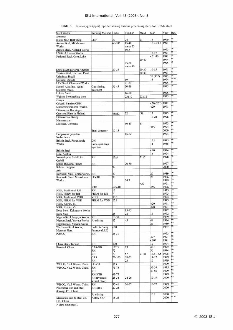
According to Fig. 4 and Eq. (1), if [%Al]�0.03–0.06, thefree oxygen is 3–5 ppm at 1 600°C. Because the free oxy-gen does not vary much, the total oxygen is a reasonable in-direct measure of the total amount of oxide inclusions inthe steel. Due to the small population of large inclusions inthe steel and the small sample size for T.O. measurement(normally 20 g), it is rare to find a large inclusion in thesample. Even if a sample has a large inclusion, it is likelydiscounted due to its anomalously high reading. Thus, T.O.content really represents the level of small oxide inclusionsonly. A low T.O. content, however, decreases the probabilityof large oxide inclusions3) as shown in Fig. 5.28) Thus totaloxygen is still a very important and common index of steelcleanliness. The T.O. measured from liquid samples rough-ly correlates with the incidence of slivers in the product, as shown in Fig. 6.51) In particular, tundish samples arecommonly taken to indicate cleanliness for slab disposition-ing. For example, Kawasaki Steel requires the T.O. intundish samples �30 ppm to warrant shipment of cold-rolled sheet without special inspection. T.O. levels between30 and 55 ppm require critical inspection. Heats above55 ppm are downgraded.52) The T.O. levels in LCAK steelat each processing step at several steel plants are compiledin Table 3. 4,16,17,22,28,41,51–96) Blanks in this table mean nodata was available.
The following general conclusions can be derived fromTable 3:1) T.O. in LCAK steel has steadily decreased with passing
years, as new technology is implemented. For example,
T.O. at Nippon Steel dropped from 40–50 ppm in1970’s,81) to 20 ppm in 1990’s82);
2) Plants with RH degassing achieve lower T.O. (10–30ppm) than plants with ladle gas-stirring (35–45 ppm).
3) T.O. generally drops after every processing step:40 ppm (ladle), 25 ppm (tundish), 20 ppm (mold), and15 ppm (slab).
2.2.2. Nitrogen PickupThe difference in nitrogen content between steelmaking
vessels (especially ladle and tundish) is an indicator of theair entrained during transfer operations. For example,Weirton restricts nitrogen pickup from ladle to tundish toless than 10 ppm for critical clean steel applications.61,97)
After deoxidation, the low dissolved oxygen content of thesteel enables rapid absorption of air. Nitrogen pickup thusserves as a crude indirect measure of total oxygen, steelcleanliness, and quality problems from reoxidation inclu-sions, as indicated in Fig. 7.61) Note that oxygen pickup isalways many times greater than the measured nitrogen pick-up, due to its faster absorption kinetics at the air steel inter-face.98) In addition, nitrogen pickup is faster when the oxy-gen and sulfur contents are low.54,64) Thus, to reduce nitro-gen pickup, deoxidation is best carried out after tapping.Plant measurements confirm this, as nitrogen pickup re-duced from 10–20 ppm for deoxidation during tapping to5 ppm after tapping.99)
Tables 416,28,53,57,64,68,87–89,97,98,100–104) and 54,28,54, 55,65,80,88,
89,105–109) summarize minimum nitrogen pick-up and nitro-gen contents measured in LCAK steel at every processingstep for several steel plants. Measurements in the tundishand mold were excluded because they tend to be high dueto sampling. These two tables reveal the following conclu-sions:� Nitrogen in LCAK steel slabs is about 30–40 ppm at
most steel plants. It is controlled mainly by the steel-making converter or electric furnace operation, but is af-fected by refining and shrouding operations.
� Nitrogen pick-up is deceasing with passing years, owingto new technology and improved operations. For exam-ple, at Sollac Dunkirk Works, nitrogen pick-up fromtundish to mold decreased from 9 ppm in 1988, to 1 ppmin 1992.
� Generally, nitrogen pick-up can be controlled at 1–3ppm from ladle to mold. With optimal transfer opera-tions to lessen air entrainment, this pickup can be low-ered during steady state casting to less than 1 ppm.Nitrogen pick-up is discussed further in the TransferOperations section of this paper.
2.2.3. Dissolved Aluminum Loss MeasurementFor LCAK steels, aluminum loss also indicates that reox-
idation has occurred. However, this indicator is a less accu-rate measure than nitrogen pickup because Al can also bereoxidized by slag.
2.2.4. Slag Composition MeasurementFirstly, analysis of the slag composition evolution before
and after operations can be interpreted to estimate inclusionabsorption to the slag. Secondly, the origin of a complexoxide inclusion can be traced to slag entrainment by match-ing the mineral and element fractions in the slag with the
ISIJ International, Vol. 43 (2003), No. 3
© 2003 ISIJ 276
Fig. 5. Relationship between T.O. and macroinclusions insteel.28)
Fig. 6. Relationship between T.O. in tundish and sliver defectindex for product.51)
ISIJ International, Vol. 43 (2003), No. 3
277 © 2003 ISIJ
Table 3. Total oxygen (ppm) reported during various processing steps for LCAK steel.

inclusion composition.28) These methods are not easy, how-ever, due to sampling difficulties and because changes inthe thermodynamic equilibrium must be taken into account.
2.2.5. Submerged Entry Nozzle (SEN) CloggingShort SEN life due to clogging is sometimes an indicator
of poor steel cleanliness. The composition of a typical clogduring LCAK steel continuous casting is: 51.7% Al2O3,44% Fe, 2.3% MnO, 1.4% SiO2, 0.6% CaO, which shows
that nozzle clogs are often caused by a simultaneousbuildup of small alumina inclusions and frozen steel.73)
Thus, SEN clogging frequency is another crude method toevaluate steel cleanliness. The cause and prevention of SENclogging was reviewed by Kemeny23) and Thomas.24)
2.3. Final Product Tests
The ultimate measure of cleanliness is to use destructivemechanical tests to measure formability, deepdrawing,
ISIJ International, Vol. 43 (2003), No. 3
© 2003 ISIJ 278
Fig. 7. Relationship between nitrogen pickup, total oxygen, and steel quality.61)
Table 4. Nitrogen pickup (ppm) reported at various steel plants.
Table 5. Nitrogen content (ppm) reported at various processing steps for LCAK steel.

and/or bending properties of the final sheet product, or fa-tigue life of test specimens or product samples. Other sheettests include the Hydrogen Induced Crack test and magne-toscopy.11) These tests are needed to reveal facts such as thepotential benefit of very small inclusions (�1 mm), whichshould not count against cleanliness.
The previous discussion shows that there is no singleideal method to evaluate steel cleanliness. Some methodsare better for quality monitoring while others are better forproblem investigation. Thus, it is necessary to combine sev-eral methods together to give a more accurate evaluation ofsteel cleanliness in a given operation. For example, NipponSteel used total oxygen measurement and EB melting forsmall inclusions, and Slime method and EB-EV for largeinclusions.39) Usinor used total oxygen measurement withFTD, OES-PDA, IA and SEM for small inclusions, andElectrolysis and MIDAS for large inclusions.39) For exam-ple, Fig. 8 compares inclusion distributions through thethickness of two slab samples measured with T.O., PDAand Image analysis.39) All three approaches show that steelA has fewer inclusions than steel B on average, and there isa peak between the loose-side surface and the center.Baosteel employed total oxygen measurement, MMO, XPS,and SEM for small inclusions, Slime and SEM for large in-clusions, nitrogen pickup for reoxidation, slag compositionanalysis to investigate inclusion absorption and slag en-trainment.28)
3. Ladle Operations for Clean Steel
Steel refining and continuous casting operations controlsteel cleanliness. For example, a systematic study of inclu-sion removal found that ladle treatment lowered inclusionsby 65–75%; the tundish removed 20–25%, although reoxi-dation sometimes occurred; and the mold removed 5–10%of the inclusions.72) Thus, ladle operations are particularlyimportant and include control of tap oxygen, FeO and MnOin the slag, ladle stirring, and inclusion modification treat-ment.
3.1. Tap Oxygen
Tap oxygen content is measured during tapping the ladleor before deoxidant addition. The tap oxygen content istypically high, ranging from 450–800 ppm at Weirton,61)
800–1 200 ppm at Great Lake Division of National Steel,110)
250–650 ppm at Nippon Steel,107) 600 ppm at Voest-AlpineLinz,71) and 700–900 ppm at WISCO No. 3 Works for IFproduction.88)
Aluminum additions to deoxidize the melt create largeamounts of Al2O3 inclusions. This suggests that a limitationon tap oxygen content should be imposed for clean steelgrades. However, as shown in Fig. 9, there is no correlationbetween tap oxygen and steel cleanliness.61) This is consis-tent with claims that 85% of the alumina clusters formedafter large aluminum additions readily float out to the ladleslag, and that the remaining clusters are smaller than30 mm.61) Naturally, the decision to ignore tap oxygen de-pends on the time available to float inclusions and on theavailability of ladle refining, which can remove most of thegenerated inclusions. Figure 10 shows how RH treatmentsreach the same final T.O. level, regardless of initial tap oxy-gen, so long as the degassing time is long enough, for ex-ample, 15 min.28) A final consideration is that the tap oxy-gen content affects the decarburization rate, important forproducing ultra low carbon steel.
3.2. FeO and MnO in Slag
An important source of reoxidation is the carryover ofslag from the steelmaking furnace to the ladle, which con-tain a high content of FeO and MnO. These liquid oxidesreact with the dissolved aluminum to generate solid alumi-
ISIJ International, Vol. 43 (2003), No. 3
279 © 2003 ISIJ
Fig. 8. Inclusion distributions along slab thickness for two steels comparing T.O. measurement, PDA method and Imageanalysis.39)
Fig. 9. Tap dissolved oxygen and final T.O. in tundish.61)

na in the liquid steel, owing to the strong favorable thermo-dynamics of the following reactions:103)
3FeO�2Al�Al2O3�3Fe
DG1°��853 700�239.9T (J mol�1).............(2)
3MnO�2Al�Al2O3�3Mn
DG1°��337 700�1.4T (J mol�1).............(3)
The higher is the FeO and MnO content in the ladle slag,the greater is the potential for reoxidation and the corre-sponding generation of alumina inclusions. Many slivers inthe final product have been traced to reoxidation that origi-nated from FeO in the ladle slag.16,17,111) Figure 11 showshow T.O. in the ladle, tundish and mold correlates roughlywith the %FeO�%MnO in the ladle slag.17,84,111–113) Theseslag impurities are particularly damaging when the ladlelining material is high in silica. Figure 12 shows a similarinfluence on the loss of dissolved Al and the increase oftundish inclusions.17,111,114)
Countermeasures to lower FeO and MnO contaminationare summarized as follows:1) Minimize slag carryover from steelmaking furnace to
ladle during tapping:• Increasing aim turndown carbon, avoiding reblows, thus
minimizing the dissolved oxygen content in the steel, canlower the amount of FeO in the furnace slag.16)
• Use of a sublance in the BOF substantially lowers the fre-quency of reblows.16)
• An efficient slag stopper, such as a slag ball (that floats insteel and sinks in slag), can lower the amount of furnaceslag carried over to the ladle during tapping to 3 kg/tsteel.115) To improve yield, other sensors are available,which detect the slag after a little has carried over. Theseinclude infra-red116) and electromagnetic systems.117)
• The furnace geometry and tap hole location can be de-signed to minimize vortexing and slag carryover.118)
• A thick ladle slag layer after tapping suggests high slagcarryover problems, as shown in the rough relationship inFig. 13.114) Ladle slag depth after skimming should be
ISIJ International, Vol. 43 (2003), No. 3
© 2003 ISIJ 280
Fig. 10. Effect of tap oxygen on T.O. removal in ladle during RHdegassing.170)
Fig. 11. Relationship between FeO�MnO in ladle slag and T.O.in steel for Ladle (RH-OB),84,111) Ladle (ArgonStirring),112) Ladle (different lining),113) Continuouscasting mold.17)
Fig. 12. Effect of FeO�MnO content in ladle slag on lowering dissoloved Al (from ladle to mold17) and from ladle totundish114)) and on increasing alumina content (measured in tundish114)).
Fig. 13. Correlation of FeO content in ladle slag with ladle slagdepth.114)

controlled to 25–40 mm.16,119)
2) Use a ladle slag reduction treatment.4,16,17,72,111,114,120,121)
Another way to lower the FeO�MnO content of the ladleslag is to add a slag conditioner (i.e. slag reduction or deox-idation treatment), which is a mixture of aluminum andburnt lime or limestone. Table 64,16,17,55,72,88,111,114,119–121)
summarizes the drop in FeO�MnO content after ladle slagreduction treatment at several steel plants. On average, thistreatment lowers FeO�MnO to below 5%, as shown in Fig.14.72) SOLLAC Dunkirk reports an accompanying sharpimprovement of coil cleanliness.72) Minimizing slag carry-over, together with adding a basic ladle slag and basic lin-ing was found to lower the ladle slag to less than 1–2%FeO�MnO, which lowered T.O. to 10 ppm for LCAKsteel.115)
3.3. Ladle Stirring Practice
Ladle stirring and refining processes, such as RH(Rheinstahl Heraeus) ladle degassing, greatly promote in-clusion growth and removal. Some metallurgical reactionsrequire strong mixing of metal and slag (e.g. desulphurisa-tion and dephosphorisation), whereas others require gentlemixing at the metal/slag interface and maintenance of anunbroken slag layer (e.g. deoxidation and inclusion re-moval). Different processes produce different stirring pow-ers, as compared in Table 7. The effect of various ladletreatments on slab inclusion levels is shown in Fig. 15.1)
This figure shows the improvement of RH vacuum treat-ment over Ar-stirring in the ladle in better steel cleanliness,which is consistent with Table 7. The pronounced benefit ofcalcium-based powder injection may be due in part to itsgreater stirring power1) in addition to its primary effect ofdeoxidization and liquefying inclusions. Together, RH de-gassing and Ca treatment dropped T.O. to 15 ppm at someplants.106) The NK-PERM process (modified RH by NKK)can lower the T.O. of LCAK steel to 5 ppm after 20 min de-
gassing.77)
The effect of stirring power on the rate of oxygen re-moval is shown in Figs. 169,77) and 17,113) which show thatincreasing stirring rate helps to remove inclusions, unless itbecomes excessive. Sufficient stirring time (�10 min)22)
after alloy addition is also important, (Fig. 17), to allow thealumina inclusions to circulate up to the slag and be re-moved. Extremely vigorous stirring or excessive treatment
ISIJ International, Vol. 43 (2003), No. 3
281 © 2003 ISIJ
Table 6. Effect of ladle slag reduction treatment reported for LCAK steel.
Table 7. Stirring powers reported for different processes.Fig. 14. Reduction of FeO content in ladle slag by
ladle slag reduction treatment.72)
Fig. 15. Effect of different ladle treatments on in-clusion level in slab.1)
Fig. 16. Effect of stirring power on deoxidation rate in variousrefining processes (Ar gas bubbling9); ASEA-SKF9);VOD and RH77)).

time are bad for several reasons. Firstly, faster upward cir-culation of steel onto the slag layer may expose an “eye” orslag-free region of the steel surface to air reoxidation113,122)
and perhaps even slag entrainment. Secondly, ladle liningerosion may become a problem. Thirdly, vigorous stirringencourages particle collisions into large macroinclu-sions.123,124) Thomas et al suggest to first stir vigorously toencourage mixing and the collision of small inclusions intolarge ones, followed by a “final stir” that slowly recirculatesthe steel to facilitate their removal into the slag while mini-mizing the generation of more large inclusions via colli-sions.123,124)
The deoxidation treatment time should be several timesthe mixing time, tm, which has been estimated as a functionof stirring power, e , by several researchers.1,9,125–129) For ex-ample, the Nakanishi equation is popular129)
tm [s]�800e [watt/ton]�0.4 ......................(4)
The specific stirring powers of different process steps,given in Table 7, can be used to estimate mixing times. Forexample, an RH treatment with 200–400 W/t stirring powerhas a mixing time of about 1.2–1.6 min. In industrial refin-ing practice, the pure degassing time is usually 5–10 min,which is 3–6 times this mixing time.
3.4. Inclusion Modification
Calcium treatment of LCAK steel is attractive because itcan liquefy the oxides and sulphides in molten steel andmodify their shape and deformability in the solidifiedsteel.30) The liquid calcium aluminates coalesce and risemore easily than the clusters of solid alumina inclusions.This facilitates their removal to the slag and lowers T.O., inaddition to avoiding nozzle clogging. To achieve liquid in-clusions, the calcium must be present in the correct propor-tion. The acceptable range is narrow and depends on thealumina content, as documented by the equilibrium phasediagram.1,130) In addition, the sulfur content must be low inorder to maintain liquid inclusions over the range of Alcontents found in Al-killed steel, as shown in Fig. 18.99)
Because Ca is so reactive, it is only effective after the steelhas been deoxidized and if slag entrapment, especially withFeO and MnO, can be avoided.
4. Tundish Operations for Clean Steel
Important phenomena taking place in the tundish are
shown schematically in Fig. 19.62) Tundish operationsgreatly affect steel cleanliness, as covered in reviews byMcLean131) and Schade.132) Depending on its operation, thetundish may act as a further refining vessel to remove inclu-sions to the slag layer or it may contaminate the steelthrough slag entrainment, reoxidation, and refractory disso-lution. The following important factors are discussed here:tundish depth and capacity, casting transitions, tundish lin-ing refractory, tundish flux, gas stirring, and tundish flowcontrol.
4.1. Tundish Depth and Capacity
Deep tundishes with a large capacity increase the resi-dence time of liquid steel and particles, so encourage inclu-sion removal as shown in Fig. 20.112) Deep tundishes alsodiscourage vortex formation, enabling more time for ladletransitions before slag entrainment becomes a problem.Tundish size for LCAK steel has gradually increased world-wide over the past 20 years, typically reaching 60–80 tonswith over 70 inches depth.
4.2. Casting Transitions
Casting transitions occur at the start of a casting se-quence, during ladle exchanges and nozzle changes, and atthe end of casting. They are responsible for most cleanli-ness defects.133) Inclusions are often generated during tran-
ISIJ International, Vol. 43 (2003), No. 3
© 2003 ISIJ 282
Fig. 17. Relationship between T.O. removal, stirring power andstirring time during deoxidation by ASEA-SKF.113)
Fig. 18. The effect of Al and S contents on inclusions in equilib-rium with Fe-Al-S melts.99)
Fig. 19. Phenomena in continuous casting tundish.62)

sitions and may persist for a long time, thus contaminatinga lot of steel.134) The sliver defect index at the beginning ofthe first heat was found to be 5 times higher than that at themiddle of the first heat and over 15 times that of successiveheats.18) During these unsteady casting periods, slag en-trainment and air absorption are more likely, which inducereoxidation problems. At National Steel, for example, T.O.in tundish during transitions is 50–70 ppm, compared withonly 25–50 ppm at steady state.22) At other plants, the dif-ference is only 3 ppm. Lukens reports transitions to haveonly 19.2 ppm, relative to 16 ppm at steady state60) andDofasco reports T.O. of 27�5 ppm during transitions and24�5 ppm during steady casting.58) At Nippon Steel, the ni-trogen pickup in tundish is 5–12 ppm during start period ofteeming and decreases to 0–2 ppm after 12.5 min teeming(steady casting state).98)
Figure 21 shows the T.O. content in the tundish duringcasting of several individual heats.58) During the first cast-ing heat, the entrainment of air and slag in the tundish pourbox due to the turbulence during ladle open is accompaniedby an initial maximum in T.O. content in the tundish (in-cluding both slag and alumina inclusions). Open pouring atstart cast causes T.O. in tundish to increase to twice normallevels for more than an entire heat (Fig. 21 Case I).58)
Several minutes of filling are needed before tundish flux
can be added. Eventually, during steady casting, the T.O.decays to lower levels, consisting mainly of alumina.
One improvement during ladle transitions is to stop theflow of liquid into the mold until the tundish is filled and tobubble gas through the stopper to promote inclusion flota-tion.22) Another improvement is to open new ladles withsubmerged shrouding. With this measure, T.O. was de-creased at Dofasco from 41�14 ppm to 31�6 ppm withmore consistent quality throughout the sequence (Fig. 21Case II).58)
Near the end of a ladle, ladle slag may enter the tundish,due in part to the vortex formed in the liquid steel near theladle exit. This phenomenon requires some steel to be keptin the ladle upon closing (e.g. A four tonne “hee”16)). In ad-dition, the tundish depth drops after ladle close, which dis-rupts normal tundish flow and may produce slag vortexing,slag entrainment, and increased total oxygen in the mold, asreported by Dofasco.58) An electro-magnetic level indicatorfor ladles is under development.
4.3. Lining Refractory
Dissolved aluminum in the liquid steel may react withoxygen sources in the lining refractory. This oxygen maycome from carbon monoxide, when carbon in the refractoryreacts with binders and impurities, or from silica refractorydecomposition (Eq. (5)).24) Silica-based tundish linings areworse than magnesia-based sprayed linings (Baosteel28) andInland Steel16)).
SiO2�4/3 Al�2/3 Al2O3�Si
DG1°��219 400�35.7T (J mol�1) ...............(5)
The extent of this reaction can be quantified by monitoringthe silicon content of the liquid steel.
Another factor is the wear rate of the lining refractories.At Kawasaki Steel Mizushima Works, three types of mate-rials (high Al2O3, Al2O3–SiC–C, and MgO–C with a wearrate of 1.0, 0.34, 0.16 mm/heat respectively) have beenadopted at the slag line, where the refractory tends to bedamaged by erosive tundish flux and slag, and the MgO–Cbrick shows the highest durability among the three.18)
4.4. Tundish Flux
The tundish flux provides several functions. Firstly, itmust insulate the molten steel both thermally (to preventexcessive heat loss) and chemically (to prevent air entrain-ment and reoxidation103)). For example, at IMEXSA Steel(Mexico), by changing tundish flux, nitrogen pickup fromladle to mold decreased from 16 to 5 ppm.103)
Secondly, in ideal circumstances, the flux should also ab-sorb inclusions to provide additional steel refining. A com-mon tundish flux is burnt rice hulls, which is inexpensive, agood insulator, and provides good coverage without crust-ing. However, rice hulls are high in silica (around 80%SiO2
28)), which can be reduced to form a source of inclu-sions (Eq. (5)). They also are very dusty and with their highcarbon content, (around 10% C28)), may contaminate ultralow carbon steel.
Basic fluxes (CaO–Al2O3–SiO2 based) are theoreticallymuch better than rice hulls at refining LCAK steels, andhave been correlated with lower oxygen in the tundish. Forexample, the T.O. decreased from 25–50 ppm to 19–35 ppm
ISIJ International, Vol. 43 (2003), No. 3
283 © 2003 ISIJ
Fig. 20. The effect of tundish bath depth on inclusion number inmold.112)
Fig. 21. The T.O. content in tundish versus time for differentheats.58) Case I: The first heat in the tundish. Case II:The intermediate heats with Bell shrouds and initialtundish covers. Case III: Intermediate heats with bafflesand initial tundish covers.

with flux basacity increasing from 0.83 to 11, measured atKawasaki Steel Mizushima Works.76) At Dofasco’s #2 MeltShop, using basic tundish flux (40% CaO, 24% Al2O3,18% MgO, 5% SiO2, 0.5% Fe2O3, 8% C), together withbaffles, significantly lowered in total oxygen fluctuation, ascompared to the initial flux (3% CaO, 10–15% Al2O3, 3%MgO, 65–75% SiO2, 2–3% Fe2O3). The T.O. decreasedfrom 41 to 21 ppm during ladle transitions and decreasedfrom 39 to 19 ppm during steady state casting.58) However,other results, such as shown in Fig. 22 found no improve-ment in T.O. between rice hulls and higher basicity flux(25.0% SiO2, 10.0% Al2O3, 59.5% CaO, 3.5% MgO).61)
This might be because the basic flux still contained toomuch silica. More likely, the basic flux was ineffective be-cause it easily forms a crust at the surface,28) owing to itsfaster melting rate and high crystallization temperature.This crust results in the evolution of an open slag-free eyearound the ladle shroud during teeming, which not onlyprovides an excessive area for reoxidation, but also allows asignificant radiative heat loss and discomfort for operatorson the ladle platform. Also, basic fluxes generally havelower viscosity, so are more easily entrained. To avoid theseproblems, AK Steel Ashland suggested a two-layer flux,with a low-melting point basic flux on the bottom to absorbthe inclusions, and a top layer of rice hulls to provide insu-lation, which lowered T.O. from 22.4 ppm to 16.4 ppm.53)
4.5. Tundish Stirring
Injecting inert gas into the tundish from its bottom im-proves mixing of the liquid steel, and promotes the collisionand removal of inclusions.60,79) At Lukens Steel Company,this technology was employed and successfully loweredT.O. to 16 ppm in tundish.60) The danger of this technologyis that any inclusions-laden bubbles which escape thetundish and become entrapped in the strand would cause se-vere defects.
4.6. Tundish Flow Control
The tundish flow pattern should be designed to increasethe liquid steel residence time, prevent “short circuiting”and promote inclusion removal. Tundish flow is controlledby its geometry, level, inlet (shroud) design and flow con-trol devices such as impact pads, weirs, dams, baffles, andfilters. The tundish impact pad, such as shown in Fig.23,59,135) is an inexpensive flow control device that preventserosion of the tundish bottom where the molten steel streamfrom the ladle impinges. More importantly, it suppressesturbulence inside the inlet zone, which lessens slag entrain-ment.135) It also diffuses incoming stream momentum and
allows the natural buoyancy of the warm incoming steel toavoid short circuiting, particularly at startup. If properlyaligned, and perhaps together with weir(s) and dam(s), apour pad can improve steel cleanliness, especially duringladle exchanges. For example, adding the pour pad at LTVSteel decreased alumina during ladle transitions from 48 to15 ppm.59) At Lukens Steel, T.O. decreased from 26 ppm(with a domed pad) to 22 ppm (with a hubcap pad).60) AtPOSCO, steel cleanliness was improved by putting 77 holesin their dam, making it act as a partial filter.84) At Dofasco’s#2 Melt Shop, using baffles improved product quality, espe-cially at ladle exchanges, thereby making the heat moreconsistent. (Fig. 21 Case III).58) Baffles combined with aninitial tundish cover lowered the average T.O. in the tundishduring steady state casting from 39�8 to 24�5 ppm.58)
Ceramic filters are very effective at removing inclu-sions.84,130) However, their cost and effective operating timebefore clogging usually make their use prohibitive.
5. Transfer Operations for Clean Steel
Transfer operations from ladle to tundish and fromtundish to mold are very important for steel cleanlinesscontrol. McPherson and McLean reviewed various aspectsof tundish-to-mold transfer operations, focusing on shrouddesign variations.136) One of the most important sources ofoxygen pickup is atmospheric reoxidation of steel duringtransfer operations. This generates inclusions which causeproduction problems such as nozzle clogging, in addition todefects in the final product. This phenomenon is minimizedby optimizing the use of shrouds, argon injection and sub-merged entry nozzle (SEN) operations.
5.1. Open Pouring and Shrouding
Using an optimized shrouding system greatly lowers re-oxidation during transfer operations. For example, using aladle shroud lowered nitrogen pickup from 24 to 3 ppm rel-ative to open pouring at Bao Steel.28) At US Steel FairfieldWorks, replacing the tundish pour box with a ladle shroudand dams lowered nitrogen pickup (ladle to tundish) from7.5 to 4 ppm, and also lowered slag entrainment during
ISIJ International, Vol. 43 (2003), No. 3
© 2003 ISIJ 284
Fig. 22. Effect of tundish flux on T.O. in tundish.61)
Fig. 23. Velocity measurements by Laser Doppler Anemometryin water model tundish with (below) and without(above) TURBOSTOP pour pad.135)
transitions.101) At British Steel Ravenscraig Works, improv-ing the shroud system from ladle to tundish, lowered the ni-trogen pickup there from 14 to 3 ppm.68) Shrouding theladle to tundish stream at another plant lowered the dis-solved aluminum loss from 130 to only 70 ppm and tolower the T.O. increase by 12 ppm.113) When pouring with-out shrouds, which is common in billet casting, the turbu-lence of the casting stream is very important. A smoothstream entrains much less oxygen than a turbulent or“ropy” stream.137) To produce a smooth stream betweentundish and mold in these operations, and the metering noz-zle edges must be maintained and high speed flow in thetundish across the nozzles must be avoided. A variety ofinert gas shrouding systems are also available to help.113,136)
5.2. Ladle Opening
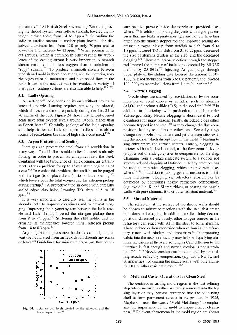
A “self-open” ladle opens on its own without having tolance the nozzle. Lancing requires removing the shroud,which allows reoxidation, especially during the first 25 to50 inches of the cast. Figure 24 shows that lanced-openedheats have total oxygen levels around 10 ppm higher thanself-open heats.60) Carefully packing of the ladle openingsand helps to realize ladle self open. Ladle sand is also asource of reoxidation because of high silica contained.138)
5.3. Argon Protection and Sealing
Inert gas can protect the steel from air reoxidation inmany ways. Tundish flux is added after the steel is alreadyflowing, in order to prevent its entrapment into the steel.Combined with the turbulence of ladle opening, air entrain-ment is thus a problem for up to 15 min at the beginning ofa cast.60) To combat this problem, the tundish can be purgedwith inert gas (to displace the air) prior to ladle opening,60)
which lowers both the total oxygen and the nitrogen pickupduring startup.64) A protective tundish cover with carefullysealed edges also helps, lowering T.O. from 41.5 to 38ppm.51)
It is very important to carefully seal the joints in theshrouds, both to improve cleanliness and to prevent clog-ging. Improving the bayonet system between the ladle noz-zle and ladle shroud, lowered the nitrogen pickup therefrom 8 to �1 ppm.57) Stiffening the SEN holder and in-creasing its maintenance lowered initial nitrogen pickupfrom 1.8 to 0.3 ppm.57)
Argon injection to pressurize the shrouds can help to pre-vent the liquid steel from air reoxidation through any jointsor leaks.24) Guidelines for minimum argon gas flow to en-
sure positive pressue inside the nozzle are provided else-where.139) In addition, flooding the joints with argon gas en-sures that any leaks aspirate inert gas and not air. Injectingargon into the tundish stopper rod and improved sealing de-creased nitrogen pickup from tundish to slab from 5 to1.8 ppm; lowered T.O in slab from 31 to 22 ppm, decreasedthe size of alumina clusters in the slab, and the decreasedclogging.68) Elsewhere, argon injection through the stopperrod lowered the number of inclusions detected by MIDASmethod by 25–80%.63) Injecting Ar gas purge throughupper plate of the sliding gate lowered the amount of 50–100 mm sized inclusions from 3 to 0.6 per cm2, and lowered100–200 mm macroinclusions from 1.4 to 0.4 per cm2.79)
5.4. Nozzle Clogging
Nozzle clogs are caused by reoxidation, or by the accu-mulation of solid oxides or sulfides, such as alumina(Al2O3) and cacium sulfide (CaS) in the steel.28,29,73,99,140) Inaddition to interfering with production, tundish nozzle/Submerged Entry Nozzle clogging is detrimental to steelcleanliness for many reasons. Firstly, dislodged clogs eitherbecome trapped in the steel,28) or they change the flux com-position, leading to defects in either case. Secondly, clogschange the nozzle flow pattern and jet characteristics exit-ing the nozzle, which disrupt flow in the mold,63) leading toslag entrainment and surface defects. Thirdly, clogging in-terferes with mold level control, as the flow control device(stopper rod or slide gate) tries to compensate for the clog.Changing from a 3-plate slidegate system to a stopper rodsystem reduced clogging at Dofasco.100) Many practices canbe used to minimize clogging, which are reviewed else-where.23,24) In addition to taking general measures to mini-mize inclusions, clogging via refractory erosion can becountered by controlling nozzle refractory composition,(e.g. avoid Na, K, and Si impurities), or coating the nozzlewalls with pure alumina, BN, or other resistant material.24)
5.5. Shroud Material
The refractory at the surface of the shroud walls shouldbe chosen to minimize reactions with the steel that createinclusions and clogging. In addition to silica lining decom-position, discussed previously, other oxygen sources in therefractory can react with Al in the steel to form alumina.These include carbon monoxide when carbon in the refrac-tory reacts with binders and impurities.23) Incorporatingcalcia into the nozzle refractory may help by liquefying alu-mina inclusions at the wall, so long as CaO diffusion to theinterface is fast enough and nozzle erosion is not a prob-lem.24,141–143) Nozzle erosion can be countered by control-ling nozzle refractory composition, (e.g. avoid Na, K, andSi impurities), or coating the nozzle walls with pure alumi-na, BN, or other resistant material.24,73)
6. Mold and Caster Operations for Clean Steel
The continuous casting mold region is the last refiningstep where inclusions either are safely removed into the topslag layer or they become entrapped into the solidifyingshell to form permanent defects in the product. In 1985,Mcpherson used the words “Mold Metallurgy” to empha-size the importance of the mold to improve steel cleanli-ness.68) Relevent phenomena in the mold region are shown
ISIJ International, Vol. 43 (2003), No. 3
285 © 2003 ISIJ
Fig. 24. Total oxygen levels created by the self-open and thelanced-open ladles.60)

in Fig. 25.144) The mold flow pattern is very important toavoid defects because it affects particle transport: removalto the top slag or entrapment by the solidifying shell. Thebehavior of the top surface of the liquid pool is particularlyimportant because it controls the entrainment of mold slag,surface defects, bubble and particle removal, and manyother problems.
6.1. Top Surface Control
Directing too much flow towards the top surface gener-ates surface defects, due to transients, turbulence at themeniscus, and inclusion problems from slag entrainment.However, decreasing surface flows too much can also gen-erate problems. These include surface defects due to themeniscus region becoming too stagnant, and a greater frac-tion of incoming inclusion particles being sent deep beforethey can be removed into the slag. Thus, a balance must befound in order to optimize the flow parameters to avoid de-fects.
6.1.1. Meniscus StagnationMost surface defects in the steel product originate in the
mold at the meniscus, where the solidifying steel shell isvery thin. The most obvious source of surface defects is thecapture of foreign particles into the solidifying shell at themeniscus. If the steel jet is directed too deep or has too lit-tle superheat, then the liquid surface will have very littlemotion and will become too cold. This can lead to freezingof the steel meniscus, which will aggravate the formation ofmeniscus hooks.145) This allows inclusions and bubbles tobe captured, the latter forming pinholes just beneath thesurface of the slab. For example, decreasing surface veloci-ty below 0.4 m/s has been measured to increase surface pin-
hole defects.146) To avoid these problems, the flow patternshould be designed to exceed a critical minimum velocityacross the top surface, estimated to be about 0.1–0.2 m/s.147)
6.1.2. Entrainment of Mold SlagMold slag can be entrained into the solidifiying shell due
to vortexing, high velocity flow that shears slag from thesurface, and turbulence at the meniscus. Slag entrainment isless likely with deeper nozzle submergence and slower cast-ing speed. To avoid shearing slag in this manner, the sur-face velocity must be kept below a critical value. This criti-cal velocity has been measured in water–oil models as afunction of viscosity and other parameters.128,148,149)
Entrainment is more difficult for shallower slag layers,higher slag viscosity, and higher slag surface tension.
The critical velocity may also be exceeded when thestanding wave becomes too severe and the interface emulsi-fies.150,151) The critical velocity also depends on the relativedensities of the steel and flux phases and the mold geome-try.151,152) High velocity surface flows also may cause emul-sification of the slag, where slag and steel intermix andeven create a foam, if too much argon gas is present.153)
This allows easy capture of particles via vortexing or sur-face shearing flow. A maximum limit of the argon gas in-jection flow rate into the nozzle was reported as a functionof casting speed, beyond which mold slag entrainment willtake place.99) Slag entrainment is also related to level varia-tions, as discussed below.
6.1.3. Level FluctuationsMany surface defects form at the meniscus due to fluctu-
ation of the liquid steel level on the top surface of the moldcavity. It is well known that automatic level control is betterthan manual level control.68) Figure 26 shows the variationin cleanliness at the start of casting with accidental disrup-tion of automatic level control.63) It has been recommendedto control mold level to �3 mm.16)
Surface level changes can be induced by the oscillationof mold, cast speed changes, too much gas injection, andasymmetrical flow in the mold. High casting speed varia-tions were observed to increase mold slag entrainment.86)
ISIJ International, Vol. 43 (2003), No. 3
© 2003 ISIJ 286
Fig. 25. Schematic of phenomena in the mold region of a steelslab caster.144)
Fig. 26. Variation in cleanliness at the start of casting with acci-dental disruption of automatic level control.63)

To decrease these problems, the top surface velocity shouldbe kept below a critical maximum velocity, which has beenestimated to be 0.3 m/s154) or 0.4 m/s.147)
6.2. Flow Pattern Control
In slab casting, the mold flow pattern varies between thetwo extremes shown in Fig. 27: single roll and doubleroll.155) For the “single roll” flow pattern, surface velocitiesand level fluctuations are high, so mold slag entrainmentand surface defects are likely. The optimal flow pattern forslab casting is likely a stable, doubleroll flow pattern from abifurcated nozzle that is not too deep. The mold flow pat-tern is controlled by adjustable parameters such as nozzlegeometry nozzle submergence depth, argon gas injectionrate, and the application of electromagnetic forces. It alsodepends on parameters which generally cannot be adjustedto accommodate the flow pattern, such as the position ofthe flow control device (slide gate or stopper rod), nozzleclogging, casting speed, strand width, and strand thickness.All of these parameters together form a system that shouldbe designed to produce an optimal flow pattern for a givenoperation.
6.2.1. Flow Pattern StabilityThe first requirement to improve steel cleanliness by the
mold flow pattern control is to minimize transients duringthe operation. It was observed that inclusion entrapmentvaries from side to side, which suggests a link with varia-tions in the transient flow structure of the lower recircula-tion zone, and the asymmetrical flow pattern, which couldbe induced by nozzle clogging as shown in Fig. 28,63) byturbulence as investigated by Thomas et al. (mathematicalsimulation)156) and Gupta (water model),157) and by exces-sive argon gas injection.149) It is especially important tokeep nearly constant the liquid steel level in the mold, pow-der feeding rate, casting speed, gas injection rate, slide gate
opening, and nozzle position (alignment and submergence).Next, the steady mold flow pattern must be designed andcontrolled.
6.2.2. Casting SpeedIncreasing casting speed tends to increase transient tur-
bulent fluctuations, and worsens the extent of flow patternasymmetries. This in turn worsens detrimental surface tur-bulence and level fluctuations.158) Improving internal clean-liness often requires limiting the maximum casting speed,such as employed by Inland to avoid pencil pipe defects.159)
Lower casting speed and avoiding variations in castingspeed both reduce the rate of slivers.51) More precisely, it isimportant to lower the liquid mass flow rate in order to con-trol the jet velocity exiting the nozzle.159)
ISIJ International, Vol. 43 (2003), No. 3
287 © 2003 ISIJ
Fig. 27. Typical mold flow patterns and corresponding top surface shape and flux layer behavior (left: 6.5SLPM, 11%gas; right: 13SLPM, 15% gas).155)
Fig. 28. Asymmetrical contamination of a continuous cast slabdue to an asymmetrical flow from the SEN clogging(N�inclusion index by using MIDAS).63)

6.2.3. Nozzle GeometryThe nozzle is a one of the few control parameters that is
relatively inexpensive to change, yet has a profound influ-ence on the flow pattern and thus on quality. Nozzle para-meters include bore size, port angle and opening size, noz-zle wall thickness, port shape (round vs. square vs. oval),number of ports (bifurcated vs. multiport), and nozzle bot-tom design (well vs. flat vs. sloped). Using a large bore orlarge port area can slightly lower the jet speed exiting thenozzle and accommodate some clogging, but this is at theexpense of increased swirl and variability in the flow.139,160)
Flow pattern is controlled mainly by the angle of the lowerports. A shallow port angle was found to increase defectsdue to powder entrapment while a deep angle increased de-fects due to alumina.112) This tradeoff shows that nozzlegeometry must be chosen, together with every other flow-control parameter, to produce an optimal flow pattern thatbalances between these two problem types.
6.2.4. Argon Gas InjectionIn addition to helping to reduce nozzle clogging, argon is
injected into the nozzle to help influence and control theflow pattern in the mold. For examaple, Fig. 27 shows thatlow gas flow tends to double-roll flow pattern, while a highargon flow rate induces single-roll flow.155) Gas injectionalso makes the flow pattern more variable, as it alternatesbetween single and double roll. To maintain a stable dou-ble-roll flow pattern, which is often optimal, the argonshould be kept safely below a critical level.155,161) Excessiveargon injection may generate transient variation of the jetsentering the mold, introduce asymmetry in the mold cavi-ty,149) and increase surface turbulence. Argon gas bubblesmay also be trapped in the solidifying steel shell to formblister defects, such as pencil pipe in the final prod-uct.153,159,162)
Gas bubbles also capture inclusions as they flow in themold.163) Figure 29 shows a typical bubble coated with in-clusion clusters.153) A tremendous number of alumina parti-cles can be captured by a single bubble, as shown in Fig.30, especially a large bubble owing to its larger surfacearea.164) This phenomenon is good for inclusion removal ifthe bubbles float out. The fundamentals of inclusion re-moval by bubble flotation in liquid steel is reviewed byZhang et al.165) However, inclusion-coated bubbles are verybad for steel cleanliness if they are entrapped by the solidi-fying shell. Entrapped solid oxide particles eventually leadto surface slivers or internal defects.153) Even if no gas is in-jected into the tundish nozzle, defects can form from bub-bles originating far upstream.163)
6.2.5. Submergence DepthIncreasing submergence depth naturally shifts the flow
pattern downward, which lessens fluctuation and instabilityof the steel/slag interface,166) and tends to improve surfacequality, as shown in Fig. 31.166) However, too deep submer-gence may send more particles deep into the lower recircu-lation zones, where a greater fraction may become en-trapped. Deeper submergence may lead to inadequate liquidslag layer thickness, meniscus freezing, and problems feed-ing slag into the interfacial gap, especially near the SEN.This increases problems with longitudinal cracks and trans-verse depressions, as shown in Fig. 31.166) For a given oper-
ation, an optimum submergence depth should exist.154,166)
6.2.6. Electromagnetic ForcesElectromagnetic forces can be applied to the molten
metal in a number of ways to substantially alter the flowpattern in the strand. Timken Harrison Plant reports thatelectromagnetic stirring of outer strands can improve thesteel cleanliness, lowering T.O in the billet from 30 to 20ppm.41) Another example is the electromagnetic brake(EMBR),167) which bends the jet and shortens its impinge-ment depth, to lessen the likelihood of capture by the solidi-fied shell deep in the strand.
6.2.7. Caster CurvatureCurved mold machines are known to entrap more parti-
ISIJ International, Vol. 43 (2003), No. 3
© 2003 ISIJ 288
Fig. 29. Slab sample showing alumina clusters in shape of for-mer bubble.171)
Fig. 30. Observed inclusions number attached to different sizebubbles for LCAK steel slab.164)
Fig. 31. Nozzle submergence depth effect on defects (longitudi-nal cracks).166)

cles than straight (vertical) mold casters,168) because theparticles gradually move upwards towards the inside radiuswhile they spiral with the liquid in the lower recirculationzone. Most particles are captured 1–3 m below the menis-cus, independent of casting speed,162,169) which correspondsto a specific distance through the strand thickness.163)
Often, inclusions concentrate at one-eighth to one-quarterof the thickness from the top of the inside radius sur-face,112,140) in addition to the surfaces, as verified by AKSteel Middletown Works (Fig. 32).52) Figure 33 shows thedifference of inclusion and pinhole distributions along theslab thickness between curved (S-type) and vertical bend-ing (VB-type) caster. The vertical bending caster has fewerinclusions and pinholes, which are distributed deeper, rela-tive to the curved caster.79) Particle entrapment defects suchas pencil pipe can be lessened if at least the top 2.5 m sec-tion of the caster is straight (vertical).
7. Summary
This paper first reviews the different definitions of cleansteel, depending on steel grade and application. Next, thedifferent methods to evaluate it are reviewed, including bothdirect and indirect methods. There is no single ideal methodto measure steel cleanliness, so it is best to couple severalmethods together to give a more accurate evaluation. Manyplants control total oxygen content and nitrogen pickup inLow Carbon Al-killed steel, which are summarized formany plants. Finally, operation practices to improve steelcleanliness at the ladle, tundish, transfer, and caster are re-viewed. Ladle operations should minimize FeO and MnO inthe slag, optimze ladle stirring practice, and possibly modify inclusions with Ca treatment. Tundish operationsshould employ a large, deep vessel with a nonreactive lin-ing and a stable basic flux cover. It should be optimizedwith flow controls such an impact pad to remove inclusions,especially during transitions. Transfer operations shouldemploy self-open ladles with optimized, nonreactive refrac-tory shrouds, argon gas protection, sealing and care toavoid reoxidation, slag entrainment and nozzle clogging.Finally, mold operations should optimize casting speed,nozzle geometry, gas injection, submergence depth, andelectromagnetic forces in order to maintain a stable moldflow pattern that encourages inclusion removal while avoid-ing the creation of new defects. The top portion of the cast-er should be vertical to minimize inclusion and bubble en-
trapment on the inside radius.
Acknowledgments
The authors are grateful for support from the NationalScience Foundation (Grant No. DMI-0115486) and theContinuous Casting Consortium at University of Illinois atUrbana-Champaign.
REFERENCES
1) K. W. Lange: Int. Mater. Rev., 33 (1988), No. 2, 53.2) W. B. Morrison: Ironmaking Steelmakaing, 16 (1989), No. 2, 123.3) R. Kiessling: Met. Sci., 15 (1980), No. 5, 161.4) T. Ehara, Y. Kurose and T. Fujimura: 79th Steelmaking Conf. Proc.,
ISS, Warrendale, PA, (1996), 485.5) N. Hirashima, R. Nishihara, Y. Takasaki, S. Kitamura, K.
Miyamoto and K. Yonezawa: Rev. Metall., 97 (2000), No. 3, 309.6) H. Lachmund, B. Prothmann, D. Huin, H. S. Raymond and H.
Gaye: Rev. Met., 95 (1998), No. 4, 487.7) A. W. Cramb: Impurities in Engineered Materials: Impact,
Reliability and Control, eds. by J. W. C. L. Briant, Marcel DekkerInc., New York, (1999), 49.
8) Z. Liu and K. Cai: Iron Steel (China), 35 (2000), No. 2, 64.9) K. Ogawa: 143rd–144th Nishiyama Memorial Seminar, ISIJ,
Tokyo, (1992), 137.10) H. Gao: Steelmaking, 16 (2000), No. 2, 38.11) B. Debiesme, I. Poissonnet, P. Choquet and F. Penet: Rev. Métall.
Cah. Inf. Tech., 90 (1993), No. 3, 387.12) M. Goransson, F. Reinholdsson and K. Willman: Iron Steelmaker,
26 (1999), No. 5, 53.13) B. G. Thomas, J. K. Brimacombe and I. V. Samarasekara: ISS
Trans., 7 (1986), 7.14) B. Mintz: ISIJ Int., 39 (1999), No. 9, 833.15) V. P. Kharchevnikov, I. L. Brodetskii, A. I. Trotsan, B. F. Belov, O.
V. Nosochenko and L. S. Lepikhov: Metallurgist, 45 (2001), No. 7-8, 285.
16) H. T. Tsai, W. J. Sammon and D. E. Hazelton: 73rd SteelmakingConf. Proc., ISS, Warrendale, PA, (1990), 49.
17) S. Chakraborty and W. Hill: 77th Steelmaking Conf. Proc., ISS,Warrendale, PA, (1994), 389.
18) H. Uehara, H. Osanai, J. Hasunuma, K. Hara, T. Nakagawa, M.Yoshida and S. Yuhara: Rev. Métall. Cah. Inf. Tech., 95 (1998), No.10, 1273.
19) K. Tanizawa: Proc. 1st Eur. Conf. Cont. Casting. 1&2, AIM,Florence, (1991), 1491.
20) T. Hansen and P. Jonsson: 2001 Electric Furnace Conf. Proc., ISS,Warrendale, PA, (2001), 59, 71.
21) Y. Miki and B. G. Thomas: CAMP-ISIJ, 11 (1998), No. 4, 807.22) S. Chakraborty and W. Hill: 78th Steelmaking Conf. Proc., ISS,
Warrendale, PA, (1995), 401.23) F. L. Kemeny: McLean Symp. Proc., ISS, Warrendale, PA, (1998),
103.24) B. G. Thomas and H. Bai: 78th Steelmaking Conf. Proc., ISS,
Warrendale, PA, (2001), 895.
ISIJ International, Vol. 43 (2003), No. 3
289 © 2003 ISIJ
Fig. 32. Average total oxygen along the thickness ofslab.52)
Fig. 33. Effect of caster curvature on steel cleanliness (left: inclusion distribution; right:pinhole distribution. VB-type: vertical bending type; S-type: Curved type).79)

25) M. Byrne, T. W. Fenicle and A. W. Cramb: ISS Trans., 10 (1989),51.
26) E. S. Szekeres: 4th Int. Conf. on Clean Steel, The Institute ofMaterials, London, (1992), 756.
27) R. A. Rege, E. S. Szekeres and W. D. Forgeng: Met. Trans. AIME, 1(1970), No. 9, 2652.
28) L. Zhang and K. Cai: BaoSteel, Report No., (1997).29) L. Ferro, J. Petroni, D. Dalmaso, J. Madias and C. Cicutti: 79th
Steelmaking Conf. Proc., ISS, Warrendale, PA, (1996), 497.30) T. Sjoqvist, S. Jung, P. Jonsson and M. Andreasson: Ironmaking
Steelmaking, 27 (2000), No. 5, 373.31) D. Mu and L. Holappa: Gov. Res. Announc. Index (USA), Report
No. PB93-179471/XAB, (1993).32) N. A. McPherson and A. McLean: Continuous Casting Vol. 7-
Tundish to Mold Transfer Operations, ISS, Warrendale, PA, (1992),1.
33) H. Suito, J. Takahashi and A. Karasev: 11st Ultra-Clean SteelSymp. of High Temperature Process Committee, ISIJ, Tokyo,(1998), 1.
34) J. Angeli, H. Flobholzer, K. Jandl, T. Kaltenbrunner, W. Posch andH. Preblinger: Rev. Metall., 96 (1999), No. 4, 521.
35) R. Rastogi and A. W. Cramb: 84th Steelmaking Conf. Proc., 84,ISS, Warrendale, PA, (2001), 789.
36) H. Matsuta, T. Sato and M. Oku: ISIJ Int., 36 (1996), Supplement,S125.
37) F. Ruby-Meyer and G. Willay: Rev. Métall. Cah. Inf. Tech., 94(1997), No. 3, 367.
38) R. Meilland, H. Hocquaux, C. Louis, l. Pollino and F. Hoffert: Rev.Métall. Cah. Inf. Tech., 96 (1999), No. 1, 88.
39) M. Burty, C. Louis, P. Dunand, P. Osmont, F. Ruby-Meyer, M.Nadif, F. Penet, T. Isono, E. Takeuchi and T. Toh: Rev. Métall. Cah.Inf. Tech., 97 (2000), No. 6, 775.
40) T. Saitoh, T. Kikuchi and K. Furuya: ISIJ Int., 36 (1996),Supplement, S121.
41) P. C. Glaws, R. V. Fryan and D. M. Keener: 74th Steelmaking Conf.Proc., ISS, Warrendale, PA, (1991), 247.
42) R. C. Sussman, M. Burns, X. Huang and B. G. Thomas:, 10thProcess Technology Conf. Proc., ISS, Warrendale, PA, (1992), 291.
43) Y. Nuri and K. Umezawa: Tetsu-to-Hagané, 75 (1989), No. 10,1897.
44) Y. Murakami: J. Res. Natl. Inst. Stand. Technol., 99 (1994), No. 4,345.
45) A. S. Venkatadri: Trans. Iron Steel Inst. Jpn., 18 (1978), 591.46) A. Chino, Y. Kawai, H. Kutsumi and M. Kawakami: ISIJ Int., 36
(1996), Supplement, S144.47) R. I. L. Guthrie and H. C. Lee: 75th Steelmaking Conf. Proc., ISS,
Warrendale, PA, (1992), 799.48) H. Yin, H. Shibata, T. Emi and M. Suzuki: ISIJ Int., 37 (1997), No.
10, 936.49) K. Ito: 165th–166th Nishiyama Memorial Seminar, ISIJ, Tokyo,
(1997), 1.50) M. Olette and C. Catellier: Clean Steel-2nd Int. Conf. on Clean
Steel, Metal Soc., London, (1983), 165.51) C. Bonilla: 78th Steelmaking Conf. Proc., ISS, Warrendale, PA,
(1995), 743.52) M. T. Burns, J. Schade and C. Newkirk: 74th Steelmaking Conf.
Proc., ISS, Warrendale, PA, (1991), 513.53) W. A. Brown, M. A. Kinney and J. Schade: Iron Steelmaker, 20
(1993), No. 6, 29.54) E. T. Turkdogan, R. S. Bogan and S. Gilbert: 74th Steelmaking
Conf. Proc., ISS, Warrendale, PA, (1991), 423.55) G. Stolte, R. Teworte and H. J. Wahle: 74th Steelmaking Conf.
Proc., ISS, Warrendale, PA, (1991), 471.56) J. Schade: Steel Technol. Int., (1993), 149.57) S. R. Cameron: 75th Steelmaking Conf. Proc., ISS, Warrendale,
PA, (1992), 327.58) P. Rasmussem: 77th Steelmaking Conf. Proc., ISS, Warrendale, PA,
(1994), 219.59) R. W. Crowley, G. D. Lawson and B. R. Jardine: 78th Steelmaking
Conf. Proc., ISS, Warrendale, PA, (1995), 629.60) K. P. Hughes, C. T. Schade and M. A. Shepherd: Iron Steelmaker,
22 (1995), No. 6, 35.61) S. D. Melville and L. Brinkmeyer: 78th Steelmaking Conf. Proc.,
ISS, Warrendale, PA, (1995), 563.62) L. Kuchar and L. Holappa: 76th Steelmaking Conf. Proc., ISS,
Warrendale, PA, (1993), 495.63) H. Jacobi, H.-J. Ehrenberg and K. Wunnenberg: Stahl Eisen, 118
(1998), No. 11, 87.64) N. Bannenberg and K. Harste: Rev. Métall. Cah. Inf. Tech., 90
(1993), No. 1, 71.65) N. Bannenberg, H. Lachmund and B. Prothmann: 77th Steelmaking
Conf. Proc., ISS, Warrendale, PA, (1994), 135.66) N. Bannenberg, R. Bruckhaus, M. Hullen, H. Lachmund and F. J.
Schmitt: Stahl Eisen, 120 (2000), No. 9, 67.67) W. K. Tiekink, J. P. Brockhoff and R. Maes: 77th Steelmaking
Conf. Proc., ISS, Warrendale, PA, (1994), 49.68) N. A. McPherson: 68th Steelmaking Conf. Proc., ISS, Warrendale,
PA, (1985), 13.69) D. V. Barradell: 2nd European Continuous Casting Conf./6th Int.
Roling Conf., VDEh, Düsseldorf, (1994), 1.70) H. Nartz: 2nd European Continuous Casting Conf./6th Int. Rolling
Conf., VDEh, Düsseldorf, (1994), 63.71) H. Flobholzer, K. Jandl, A. Jungreithmeier and A. Viertauer: Stahl
Eisen, 118 (1998), No. 8, 63.72) M. Burty, P. Dunand and J. P. Pitt: 80th Steelmaking Conf. Proc.,
ISS, Warrendale, PA, (1997), 647.73) Y. Vermeulen, B. Coletti, P. Wollants, B. Blanpain and F. Haers:
Steel Res., 71 (2000), No. 10, 391.74) H. Kondo, K. Kameyama, H. Nishikawa, K. Hamagami and T.
Fujii: 1989 Steelmaking Conf. Proc., ISS, Warrendale, PA, (1989),191.
75) M. Nadif and D. Neyret: Rev. Métall. Cah. Inf. Tech., 87 (1990),No. 2, 146.
76) N. Bessho, H. Yamasaki, T. Fujii, T. Nozaki and S. Hiwasa: ISIJInt., 32 (1992), No. 1, 157.
77) M. Matsuno, Y. Kikuchi, M. Komatsu, M. Arai, K. Watanabe andH. Nakashima: Iron Steelmaker, 20 (1993), No. 7, 35.
78) K. Uemura: ISIJ Int., 32 (1992), No. 1, 150.79) Y. Shirota: 143rd–144th Nishiyama Memorial Seminar, ISIJ, Tokyo,
(1992), 167.80) T. Hatakeyama, Y. Mizukami, K. Iga and M. Oita: 72nd
Steelmaking Conf. Proc., ISS, Warrendale, PA, (1989), 219.81) K. Okohira, N. Sato and H. Mori: Trans. Iron Steel Inst. Jpn., 14
(1974), 103.82) G. Stolte: Stahl Eisen, 109 (1989), No. 22, 1089.83) Japan Steel Works, Ltd.: Trans Iron Steel Inst. Jpn., 27 (1987), 312.84) C. M. Lee, I. S. Choi, B. G. Bak and J. M. Lee: Rev. Métall. Cah.
Inf. Tech., 90 (1993), No. 4, 501.85) J. Li: 7th China Steel Quality and Inclusion Symp. Proc., China
Socity of Metal, Beijing, (1995), 12.86) G. Shi, L. Zhang, Y. Zheng, J. Zhi, W. Wang, J. Zhang, W. Wang
and X. Wang: Iron Steel (China), 35 (2000), No. 3, 12.87) X. Wang: Univ. Sci. Tech. Beijing, China, private communication,
(2000).88) J. Cui: Baosteel Research, Shanghai, China, private communica-
tion, (2000).89) L. Wang: Master Thesis, University of Science Technology Beijing,
(1996).90) Z. Yu: Iron Steel (China), 34 (1999), Supplement, 316.91) J. Liu, Z. Zhang and L. Liu: Iron Steel (China), 34 (1999), supple-
ment, 527.92) Y. Zhou, F. Yuan, Q. Ma, W. Wang, W. Wang, Y. Qiu and X. Wang:
Iron Steel (China), 36 (2001), No. 2, 16.93) Y. Li, N. Xue and M. Wang: Steelmaking, 16 (2000), No. 6, 38.94) Y. Li, D. Zhang, K. Zhao, M. Li, K. Cai and L. Dong: Iron Steel
(China), 35 (2000), No. 8, 21.95) D. Fan and G. Liu: Steelmaking, 16 (2000), No. 1, 43.96) J. Liu, Z. Zhang and L. Liu: Steelmaking, 15 (1999), No. 1, 43.97) S. Armstrong: 76th Steelmaking Conf. Proc., ISS, Warrendale, PA,
(1993), 475.98) K. Sasai and Y. Mizukami: ISIJ Int., 40 (2000), No. 1, 40.99) R. J. Fruehan: Iron Steelmaker, 23 (1996), No. 7, 25.
100) S. R. Cameron, D. L. Creces and K. B. Smith: 78th SteelmakingConf. Proc., ISS, Warrendale, PA, (1995), 255.
101) C. Perkin and K. Flynn: 78th Steelmaking Conf. Proc., ISS,Warrendale, PA, (1995), 431.
ISIJ International, Vol. 43 (2003), No. 3
© 2003 ISIJ 290

102) P. Tassot, A. D. Anselme and J. P. Radot: 78th Steelmaking Conf.Proc., ISS, Warrendale, PA, (1995), 465.
103) V. H. Tapia, R. D. Morales, J. Camacho and G. Lugo: 79thSteelmaking Conf. Proc., ISS, Warrendale, PA, (1996), 539.
104) Z. Luo and K. Cai: Iron Steel (China), 34 (1999), Supplement, 531.105) D. Brachet, C. Gatellier, Y. Zbaczyniak, M. Nadif, P. Chapellier and
A. Leclercq: Rev. Métall. Cah. Inf. Tech., 90 (1993), No. 1, 77.106) H. P. Haastert: Stahl Eisen, 111 (1991), No. 3, 102.107) M. Yano, S. Kitamura, K. Harashima, K. Azuma, N. Ishiwata and
Y. Obana: 77th Steelmaking Conf. Proc., ISS, Warrendale, PA,(1994), 117.
108) H. Okano, M. Satoh and K. Tada: 80th Steelmaking Conf. Proc.,ISS, Warrendale, PA, (1997), 127.
109) S. Jiang: 8th China Steelmaking Conf. Proc., CSM, Beijing, China,(1994), 12.
110) S. Chakraborty and D. A. Dukelow: 79th Steelmaking Conf. Proc.,ISS, Warrandale, PA, (1996), 487.
111) K. F. Hille, F. R. Papay, N. Genma and M. L. Miller: 74thSteelmaking Conf. Proc., ISS, Warrendale, PA, (1991), 419.
112) M. Hashio, N. Tokuda, M. Kawasaki and T. Watanabe: ContinuousCasting of Steel, Secondary Process Technology Conf., Vol. 2, ISS,Warrendale, PA, (1981), 65.
113) K. Schwerdtfeger: Arch. Eisenhüttenwes., 54 (1983), 87.114) K. V. Ahlborg, T. H. Bieniosek and J. H. Tucci: 76th Steelmaking
Conf. Proc., ISS, Warrendale, PA, (1993), 469.115) T. Emi: 8th China Steelmaking Conf. Proc., CSM, Beijing, China,
(1994), 8.116) D. A. Goldstein, A. Sharan and H. A. Stofanak: 83th Steelmaking
Conf. Proc., ISS, Warrendale, PA, (2000), 331.117) R. C. Novak, D. G. Hill and J. P. Hoffman: Iron Steelmaker, 12
(1985), No. 8, 28.118) K.-P. Johann and H. Knapp: 7th European Electric Steelmaking
Conf., Vol. II, Associazione Italiana di Metallurgia, Milano, (2002),2.41.
119) E. Wong and S. Ritza: Iron Steelmaker, 26 (1999), No. 7, 23.120) S. B. Ahn, J. S. Kim, C. H. Yim, J. Y. Chung and Y. H. Kim. 81th
Steelmaking Conf. Proc., ISS, Warrendale, PA, (1998), 3.121) K. Lin: private communication, (2001).122) T. Fujisawa: 126th–127th Nishiyama Memorial Seminar, ISIJ,
Tokyo, (1988), 89.123) Y. Miki, B. G. Thomas, A. Denissov and Y. Shimada: Iron
Steelmaker, 24 (1997), No. 8, 31.124) L. Zhang and B. G. Thomas: 7th European Electric Steelmaking
Conf., Vol. II, Associazione Italiana di Metallurgia, Milano, (2002),2.77.
125) M. Sano: Shigen-to-Sozai (Japan), 110 (1994), No. 3, 177.126) Y. Takatsuka and M. Iguchi: ISIJ Int., 41 (2001), No. 2, 124.127) K. Okumura and M. Sano: ISIJ Int., 41 (2001), No. 3, 234.128) S. Asai: 100th–101th Nishiyama Memorial Seminar, ISIJ, Tokyo,
(1984), 65.129) K. Nakanishi, T. Fuji and J. Szekely: Ironmaking Steelmaking, 2
(1975), No. 3, 193.130) H. Horiuchi: 126th–127th Nishiyama Memorial Seminar, ISIJ,
Tokyo, (1988), 1.131) M. McLean: 71th Steelmaking Conf. Proc., ISS, Warrendale, PA,
(1988), 3.132) J. Schade: Continuous Casting, 10, ISS, Warrendale, PA, (2000), 1.133) S. H. Nam, O. D. Kwon, D. W. Yang, M. R. Kim, H. B. Lee, J. I.
Kim and B. D. You: 78th Steelmaking Conf. Proc., ISS,Warrendale, PA, (1995), 551.
134) Y. Miki and B. G. Thomas: Metall. Mater. Trans. B, 30B (1999),No. 4, 639.
135) H.-J. Odenthal, R. Bolling, H. Pfeifer, J.-F. Holzhauser and F.-J.Wahlers: Steel Res., 72 (2001), No. 11�12, 466.
136) N. A. McPherson and A. McLean: Continuous Casting Vol. 6-Tundish to Mold Transfer Operations, ISS, Warrendale, PA, (1992),1.
137) I. V. Samarasekera, J. K. Brimacombe, S. Kumar and A. McLean:34th Proc. Int. Symp. on Near- Net-Shape Casting in the Minimills,eds. by I. V. Samarasekera and J. K. Brimacombe, Canadian Inst.Min. Met., Montreal, Canada, (1995), 135.
138) R. Engel, R. Marr and E. Pretorius: Iron Steelmaker, 23 (1996), No.9, 79.
139) H. Bai and B. G. Thomas: Metall. Mater. Trans. B, 32B (2001), No.2, 269.
140) T. Ohno, T. Ohashi, H. Matsunaga, T. Hiromoto and K. Kumai:Trans. Iron Steel Inst. Jpn., 15 (1974), 407.
141) P. M. Benson, Q. K. Robinson and H. K. Park: 76th SteelmakingConf. Proc., ISS, Warrendale, PA, (1993), 533.
142) S. Ogibayashi, M. Uchimura, Y. Maruki, R. Mizukoshi and K.Tanizawa: 75th Steelmaking Conf. Proc., ISS, Warrendale, PA,(1992), 337.
143) G. T. Moulden and R. Sabol: 83th Steelmaking Conf. Proc., ISS,Warrendale, PA, (2000), 161.
144) B. G. Thomas: 59th Electric Furnace Conf. and 19th ProcessTechnology Conf. Proc., ISS, Warrendale, PA, (2001), 3.
145) J. Birat, M. Larrecq, J. Lamant and J. Petegnief: Mold Operation forQuality and Productivity, eds. by A.W. Cramb and E. Szekeres, ISS,Warrendale, PA, (1991), 3.
146) M. Hanao, M. Kawamoto, H. Mizukami and K. Hanazaki: 82thSteelmaking Conf. Proc., ISS, Warrendale, PA, (1999), 63.
147) J. Kubota, K. Okimoto, A. Shirayama and H. Murakami: 74thSteelmaking Conf. Proc., ISS, Warrendale, PA, (1991), 233.
148) J. M. Harman and A. W. Cramb: 79th Steelmaking Conf. Proc.,ISS, Warrendale, PA, (1996), 773.
149) Z. Wang, K. Mukai, Z. Ma, M. Nishi, H. Tsukamoto and F. Shi:ISIJ Int., 39 (1999), No. 8, 795.
150) T. Honeyands and J. Herbertson: Steel Res., 66 (1995), No. 7, 287.151) A. Theodorakakos and G. Bergeles: Metall. Mater. Trans. B, 29B
(1998), No. 6, 1321.152) G. A. Panaras, A. Theodorakakos and G. Bergeles: Metall. Mater.
Trans. B, 29B (1998), No. 5, 1117.153) W. H. Emling, T. A. Waugaman, S. L. Feldbauer and A. W. Cramb:
77th Steelmaking Conf. Proc., ISS, Warrendale, PA, (1994), 371.154) J. Herbertson, Q. L. He, P. J. Flint and R. B. Mahapatra: 74th
Steelmaking Conf. Proc., ISS, Warrendale, PA, (1991), 171.155) M. B. Assar, P. H. Dauby and G. D. Lawson: 83th Steelmaking
Conf. Proc., ISS, Warrendale, PA, (2000), 397.156) B. G. Thomas: Continuous Casting Consortium Annual Report,
University of Illinois, Urbana, IL, (2001).157) D. Gupta, S. Chakraborty and A. K. Lahiri: ISIJ Int., 37 (1997), No.
7, 654.158) I. Hamill and T. Lucas: Fluid Flow Phenomena in Metals
Processing, Minerals, Metals and Materials Society, Warrendale,PA, (1999), 279.
159) J. Knoepke, M. Hubbard, J. Kelly, R. Kittridge and J. Lucas: 77thSteelmaking Conf. Proc., .ISS, Warrendale, PA, (1994), 381.
160) F. M. Najjar, B. G. Thomas and D. E. Hershey: Metall. Trans. B,26B (1995), No. 4, 749.
161) T. Shi and B. G. Thomas: Continuous Casting Consortium Report,University of Illinois, Urbana, IL, (2001).
162) B. G. Thomas, A. Denissov and H. Bai: 80th Steelmaking Conf.Proc., ISS, Warrendale, PA., (1997), 375.
163) G. Abbel, W. Damen, G. de Gendt and W. Tiekink: ISIJ Int., 36(1996), S219.
164) L. Kiriha, H. Tosawa and K. Sorimachi: CAMP-ISIJ, 13 (2000),120.
165) L. Zhang and S. Taniguchi: Int. Mater. Rev., 45 (2000), No. 2, 59.166) E. Hoffken, H. Lax and G. Pietzko: 4th Int. Conf. Continuous
Casting, Vol. 2, Verlag Stahl Eisen mbH, Düsseldorf, (1988), 461.167) R. H. M. G. Nabben, R. P. J. Duursma, A. A. Kamperman and J. L.
Lagerberg: Ironmaking Steelmaking, 25 (1998), No. 5, 403.168) H. Tanaka, R. Tsujino, A. Imamura, R. Nishihara and J. Konishi:
ISIJ Int., 34 (1994), No. 6, 498.169) N. Bessho, R. Yoda, H. Yamasaki, T. Fujii, T. Nozaki and S.
Takatori: Iron Steelmaker, 18 (1991), No. 4, 39.170) L. Zhang and K. Cai: 84th Steelmaking Conf. Proc., ISS,
Warrandale, PA, (2001), 275.171) W. H. Emling, T. A. Waugaman, S. L. Feldbauer and A. W. Cramb:
77th Steelmaking Conf. Proc., ISS, Warrendale, PA, (1994), 371.172) T. B. Braun, J. F. Elliott and M. C. Flemings: Metall. Trans. B, 10B
(1979), No. 6, 171.
ISIJ International, Vol. 43 (2003), No. 3
291 © 2003 ISIJ