Embed Size (px)
Citation preview
International Research Journal of Engineering and Technology (IRJET) e-ISSN: 2395 -0056
Volume: 03 Issue: 06|June -2016 www.irjet.net p-ISSN: 23950072
© 2016, IRJET | Impact Factor value: 4.45 | ISO 9001:2008 Certified Journal | Page 1463
REVIEW ON SANDWITCH COMPOSITE PANNEL
Prof. Anup M. Gawande1, Prof. Vijay S. Ghorade 2, Prof. Ganesh A. Kadam3
1 Prof. Anup M. Gawande, Department of Mechanical Engineering, STC SERT Khamgaon, Maharashtra, India 2 Prof. Vijay S. Ghorade, Department of Mechanical Engineering, STC SERT Khamgaon, Maharashtra, India
3 Prof. Ganesh A. Kadam, Department of Mechanical Engineering, SKNSITS Lonavala, Maharashtra, India ---------------------------------------------------------------------***---------------------------------------------------------------------Abstract- The investigations carried out in the area of
combination of polyurethane foam and natural cork as
core inserts in the multilayer hybrid composite
materials. For the estimation of modal parameters like
modal frequency and modal damping characteristics of
the materials, the general approach is more frequently
used are experimental techniques such as Fast Fourier
Transformation [FFT]. Polyurethane foams of different
densities are combined with higher damping capability
materials like natural cork to form multilayer hybrid
cored sandwich panels [HSW], and their performance
for vibration is carried through experimental FFT
analyzers & by FEA. In FEA (modal analysis) 3D part
modeling of composite panels is done and assembly also
carried out then proper material selected. After that
meshing of parts carried out and number of modes
shapes selected on which analysis takes place and
results are collected by using FEA. Such that experiment
can be carried out by using FFT analyzer in which
hammering is done on the composite panel and the
hammer has input signal of excitation. And output
signal is given to the accelerometer, after those
readings are recorded by FFT and data is collected.
1. INTRODUCTION
Advances in analytical techniques, combined with
the availability of newer and more efficient materials, have
facilitated the design of lighter and more flexible
structures. These advanced structures are known to be
much more responsive to dynamic loadings than their
solid predecessors. As a consequence, it has become more
important to accurately assess dynamic properties, such
as damping and natural Frequencies. In particular,
damping which is a measure of energy dissipation in
vibrating systems plays a major role in the assessment of
serviceability limit states. The damping ratio is a
parameterusually that characterizes the frequency
response of a second order ordinary differential equation.
Sandwich panels are designed to take higher shear loads
and also bear the characteristics of higher vibration
damping capacity. The sandwich panels absorb large a
mounts of energy; they are also often used as a “cushion”
against external loads. These materials are lightweight,
have good shear properties and higher strength.
Composite panels have high strength to weight ratios
hence have been successfully used for many years in the
aviation and aerospace industries, as well as in marine,
and mechanical and civil engineering applications. Also
they Have attendant high stiffness. The use of the
sandwich constructions in the aerospace structures can be
traced back to Second World War when British De
Havilland Mosquito bomber had utilized the sandwich
constructions. In the early use, the sandwich structure was
very simple in construction, with simple cloth, fabric or
thin metal facings were used and soft wood were used as
the core. The conventional sandwich construction
comprises a relatively thick core of low-density material
which separates top and bottom faceplates (or faces or
facings) which are relatively thin but stiff. The materials
that have been used in sandwich construction have been
many and varied but in quite recent times interest in
sandwich construction has increased with the
introduction of new materials for use in the facings (e.g.
fiber- reinforced composite laminated material) and in the
core (e.g. solid foams). Use of Sandwich construction for
an aircraft structural component is very common to the
present day. One of the primary requirements of
aerospace structural materials is that they should have
low density, very stiff and strong. Sandwich panels are
thin-walled structures fabricated from two flat sheets
separated by a low density core. Sandwich panels have a
very high stiffness to weight ratio with respect equivalent
solid plate because of low density core. FEA modeling is
developed by consideration of rotary inertia.
In the light of the above, undoubtedly very
meager information is available on the investigations
carried out in the area of combination of polyurethane
foam and natural cork as core inserts in the multilayer
hybrid composite materials. For the estimation of modal
parameters like modal frequency and modal damping
characteristics of the materials, the general approach
more frequently used are experimental techniques such as
Fast Fourier Transformation [FFT] and shaker testing
techniques. However research in the area of estimating the
damping ratio of the material from their elastic and
International Research Journal of Engineering and Technology (IRJET) e-ISSN: 2395 -0056
Volume: 03 Issue: 06|June -2016 www.irjet.net p-ISSN: 23950072
© 2016, IRJET | Impact Factor value: 4.45 | ISO 9001:2008 Certified Journal | Page 1464
physical constants is very scanty & scarce. Hence in this
work an attempt has been made to evaluate damping ratio
of sandwich composite through elastic constants.
Polyurethane foams of different densities are combined
with higher damping capability materials like natural cork
to form multilayer hybrid cored sandwich panels [HSW],
and their performance for vibration damping is carried
through experimental FFT analyzers. In the search for
designing and fabricating sandwich panels with higher
damping capability, efforts have been made to vary the
volume fraction of the core material of the sandwich and
to evaluate the damping capacity of these materials(1).
A. Sandwich Structure Types:
Detailed treatment of the behavior of honeycombed and
other types of sandwich panels can be found in
monographs by Plantema and Allen. These structures are
characterized by a common feature of two flat facing
sheets, but the core takes many generic forms; continuous
corrugated sheet or a number of discrete but aligned
longitudinal top-hat, zed or channel sections. The core and
facing plates are joined by spot-welds, rivets or self-
tapping screws.
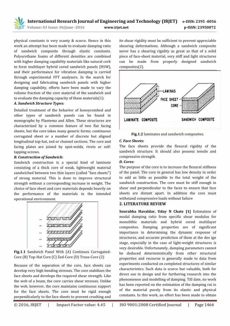
B. Construction of Sandwich:
Sandwich construction is a special kind of laminate
consisting of a thick core of weak, lightweight material
sandwiched between two thin layers (called "face sheets")
of strong material. This is done to improve structural
strength without a corresponding increase in weight. The
choice of face sheet and core materials depends heavily on
the performance of the materials in the intended
operational environment.
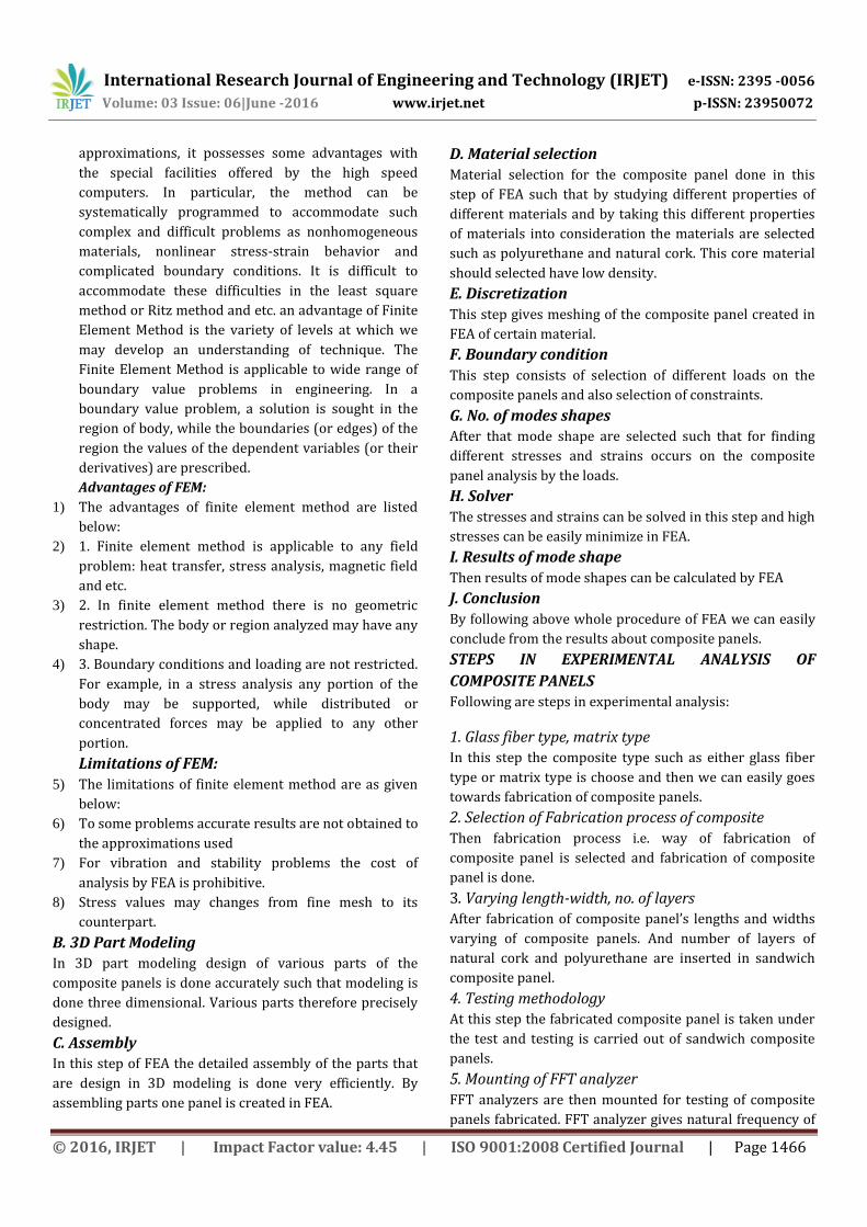
Fig.1.1 Sandwich Panel With (A) Continues Corrugated-
Core (B) Top-Hat Core (C) Zed-Core (D) Truss-Core (2)
Because of the separation of the core, face sheets can
develop very high bending stresses. The core stabilizes the
face sheets and develops the required shear strength. Like
the web of a beam, the core carries shear stresses. Unlike
the web, however, the core maintains continuous support
for the face sheets. The core must be rigid enough
perpendicularly to the face sheets to prevent crushing and
its shear rigidity must be sufficient to prevent appreciable
shearing deformations. Although a sandwich composite
never has a shearing rigidity as great as that of a solid
piece of face-sheet material, very stiff and light structures
can be made from properly designed sandwich
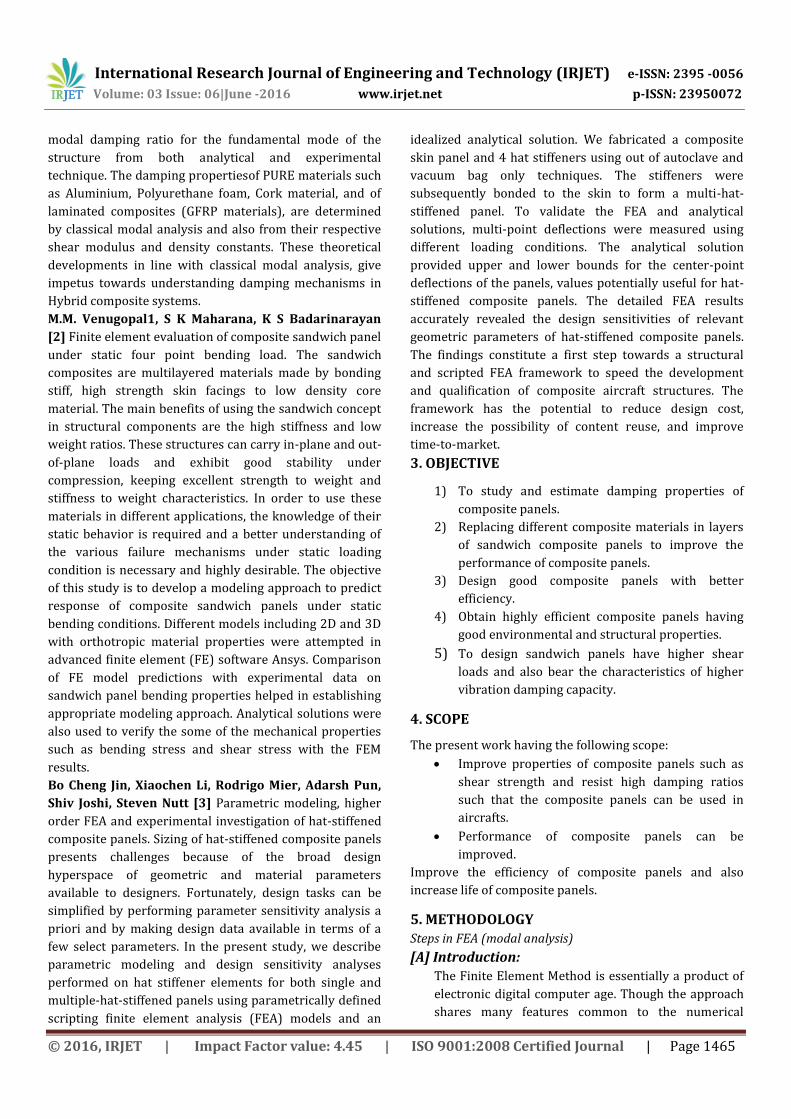
composites(2).
Fig.1.2 laminates and sandwich composites.
C. Face Sheets:
The face sheets provide the flexural rigidity of the
sandwich structure. It should also possess tensile and
compressive strength.
D. Cores:
The purpose of the core is to increase the flexural stiffness
of the panel. The core in general has low density in order
to add as little as possible to the total weight of the
sandwich construction. The core must be stiff enough in
shear and perpendicular to the faces to ensure that face
sheets are distant apart. In addition the core must
withstand compressive loads without failure
2. LITERATURE REVIEW
Sourabha Havaldar, Uday N Chate [1] Estimation of
modal damping ratio from specific shear modulus for
monolithic materials and hybrid cored multilayer
composites. Damping properties are of significant
importance in determining the dynamic response of
structures, and accurate prediction of them at the des ign
stage, especially in the case of light-weight structures is
very desirable. Unfortunately, damping parameters cannot
be deduced deterministically from other structural
properties and recourse is generally made to data from
experiments conducted on completed structures of similar
characteristics. Such data is scarce but valuable, both for
direct use in design and for furthering research into the
phenomenon and modelling of damping. Till date, no work
has been reported on the estimation of the damping rat io
of the material purely from its elastic and physical
constants. In this work, an effort has been made to obtain
International Research Journal of Engineering and Technology (IRJET) e-ISSN: 2395 -0056
Volume: 03 Issue: 06|June -2016 www.irjet.net p-ISSN: 23950072
© 2016, IRJET | Impact Factor value: 4.45 | ISO 9001:2008 Certified Journal | Page 1465
modal damping ratio for the fundamental mode of the
structure from both analytical and experimental
technique. The damping propertiesof PURE materials such
as Aluminium, Polyurethane foam, Cork material, and of
laminated composites (GFRP materials), are determined
by classical modal analysis and also from their respective
shear modulus and density constants. These theoretical
developments in line with classical modal analysis, give
impetus towards understanding damping mechanisms in
Hybrid composite systems.
M.M. Venugopal1, S K Maharana, K S Badarinarayan
[2] Finite element evaluation of composite sandwich panel
under static four point bending load. The sandwich
composites are multilayered materials made by bonding
stiff, high strength skin facings to low density core
material. The main benefits of using the sandwich concept
in structural components are the high stiffness and low
weight ratios. These structures can carry in-plane and out-
of-plane loads and exhibit good stability under
compression, keeping excellent strength to weight and
stiffness to weight characteristics. In order to use these
materials in different applications, the knowledge of their
static behavior is required and a better understanding of
the various failure mechanisms under static loading
condition is necessary and highly desirable. The objective
of this study is to develop a modeling approach to predict
response of composite sandwich panels under static
bending conditions. Different models including 2D and 3D
with orthotropic material properties were attempted in
advanced finite element (FE) software Ansys. Comparison
of FE model predictions with experimental data on
sandwich panel bending properties helped in establishing
appropriate modeling approach. Analytical solutions were
also used to verify the some of the mechanical properties
such as bending stress and shear stress with the FEM
results.
Bo Cheng Jin, Xiaochen Li, Rodrigo Mier, Adarsh Pun,
Shiv Joshi, Steven Nutt [3] Parametric modeling, higher
order FEA and experimental investigation of hat-stiffened
composite panels. Sizing of hat-stiffened composite panels
presents challenges because of the broad design
hyperspace of geometric and material parameters
available to designers. Fortunately, design tasks can be
simplified by performing parameter sensitivity analysis a
priori and by making design data available in terms of a
few select parameters. In the present study, we describe
parametric modeling and design sensitivity analyses
performed on hat stiffener elements for both single and
multiple-hat-stiffened panels using parametrically defined
scripting finite element analysis (FEA) models and an
idealized analytical solution. We fabricated a composite
skin panel and 4 hat stiffeners using out of autoclave and
vacuum bag only techniques. The stiffeners were
subsequently bonded to the skin to form a multi-hat-
stiffened panel. To validate the FEA and analytical
solutions, multi-point deflections were measured using
different loading conditions. The analytical solution
provided upper and lower bounds for the center-point
deflections of the panels, values potentially useful for hat-
stiffened composite panels. The detailed FEA results
accurately revealed the design sensitivities of relevant
geometric parameters of hat-stiffened composite panels.
The findings constitute a first step towards a structural
and scripted FEA framework to speed the development
and qualification of composite aircraft structures. The
framework has the potential to reduce design cost,
increase the possibility of content reuse, and improve
time-to-market.
3. OBJECTIVE
1) To study and estimate damping properties of
composite panels.
2) Replacing different composite materials in layers
of sandwich composite panels to improve the
performance of composite panels.
3) Design good composite panels with better
efficiency.
4) Obtain highly efficient composite panels having
good environmental and structural properties.
5) To design sandwich panels have higher shear
loads and also bear the characteristics of higher
vibration damping capacity.
4. SCOPE
The present work having the following scope:
Improve properties of composite panels such as
shear strength and resist high damping ratios
such that the composite panels can be used in
aircrafts.
Performance of composite panels can be
improved.
Improve the efficiency of composite panels and also
increase life of composite panels.
5. METHODOLOGY
Steps in FEA (modal analysis)
[A] Introduction:
The Finite Element Method is essentially a product of
electronic digital computer age. Though the approach
shares many features common to the numerical
International Research Journal of Engineering and Technology (IRJET) e-ISSN: 2395 -0056
Volume: 03 Issue: 06|June -2016 www.irjet.net p-ISSN: 23950072
© 2016, IRJET | Impact Factor value: 4.45 | ISO 9001:2008 Certified Journal | Page 1466
approximations, it possesses some advantages with
the special facilities offered by the high speed
computers. In particular, the method can be
systematically programmed to accommodate such
complex and difficult problems as nonhomogeneous
materials, nonlinear stress-strain behavior and
complicated boundary conditions. It is difficult to
accommodate these difficulties in the least square
method or Ritz method and etc. an advantage of Finite
Element Method is the variety of levels at which we
may develop an understanding of technique. The
Finite Element Method is applicable to wide range of
boundary value problems in engineering. In a
boundary value problem, a solution is sought in the
region of body, while the boundaries (or edges) of the
region the values of the dependent variables (or their
derivatives) are prescribed.
Advantages of FEM:
1) The advantages of finite element method are listed
below:
2) 1. Finite element method is applicable to any field
problem: heat transfer, stress analysis, magnetic field
and etc.
3) 2. In finite element method there is no geometric
restriction. The body or region analyzed may have any
shape.
4) 3. Boundary conditions and loading are not restricted.
For example, in a stress analysis any portion of the
body may be supported, while distributed or
concentrated forces may be applied to any other
portion.
Limitations of FEM:
5) The limitations of finite element method are as given
below:
6) To some problems accurate results are not obtained to
the approximations used
7) For vibration and stability problems the cost of
analysis by FEA is prohibitive.
8) Stress values may changes from fine mesh to its
counterpart.
B. 3D Part Modeling In 3D part modeling design of various parts of the
composite panels is done accurately such that modeling is
done three dimensional. Various parts therefore precisely
designed.
C. Assembly In this step of FEA the detailed assembly of the parts that
are design in 3D modeling is done very efficiently. By
assembling parts one panel is created in FEA.
D. Material selection
Material selection for the composite panel done in this
step of FEA such that by studying different properties of
different materials and by taking this different properties
of materials into consideration the materials are selected
such as polyurethane and natural cork. This core material
should selected have low density.
E. Discretization
This step gives meshing of the composite panel created in
FEA of certain material.
F. Boundary condition
This step consists of selection of different loads on the
composite panels and also selection of constraints.
G. No. of modes shapes After that mode shape are selected such that for finding
different stresses and strains occurs on the composite
panel analysis by the loads.
H. Solver
The stresses and strains can be solved in this step and high
stresses can be easily minimize in FEA.
I. Results of mode shape
Then results of mode shapes can be calculated by FEA
J. Conclusion
By following above whole procedure of FEA we can easily
conclude from the results about composite panels.
STEPS IN EXPERIMENTAL ANALYSIS OF
COMPOSITE PANELS
Following are steps in experimental analysis:
1. Glass fiber type, matrix type
In this step the composite type such as either glass fiber
type or matrix type is choose and then we can easily goes
towards fabrication of composite panels.
2. Selection of Fabrication process of composite
Then fabrication process i.e. way of fabrication of
composite panel is selected and fabrication of composite
panel is done.
3. Varying length-width, no. of layers After fabrication of composite panel’s lengths and widths
varying of composite panels. And number of layers of
natural cork and polyurethane are inserted in sandwich
composite panel.
4. Testing methodology At this step the fabricated composite panel is taken under
the test and testing is carried out of sandwich composite
panels.
5. Mounting of FFT analyzer
FFT analyzers are then mounted for testing of composite
panels fabricated. FFT analyzer gives natural frequency of
International Research Journal of Engineering and Technology (IRJET) e-ISSN: 2395 -0056
Volume: 03 Issue: 06|June -2016 www.irjet.net p-ISSN: 23950072
© 2016, IRJET | Impact Factor value: 4.45 | ISO 9001:2008 Certified Journal | Page 1467
vibrations produced in fabricated composite panels. A
signal which is represented an equation or a graph or a set
of data points where frequency is dependent variable, by
using Fourier Transform. This instrument converts the
input signal with time as independent variable into
frequency spectrum and displays in graphical form.
6. Input signal of excitation by Impact hammer
Input signal of excitation is given by impact hammer by
hammering on composite panel and input of hammer i.e.
applied load by hammer is noted.
7. Output signal by accelerometer And output signal we obtained on the accelerometer.
Accelerometer is used to determine vibration in rotating
machinery.
8. Readings & visualization of vibration
Readings and visualization is carried out in this step such
that by using FFT analyzer and accelerometer.
9. Data collection Thus data can` be easily collected using accelerometer.6.
6. EXPECTED OUTCOMES Paragraph comes content here. Paragraph comes content here. Paragraph comes content here. Paragraph comes content here. Paragraph comes content here. Paragraph comes content here. Paragraph comes content here. Paragraph comes content here. Paragraph comes content here. Paragraph comes content here. Paragraph comes content here. Paragraph comes content here.
REFERENCES [1] Sourabha Havaldar, Uday N Chate “Estimation of
modal damping ratio from specific shear modulus for
monolithic materials and hybrid cored multilayer
compositites”. 2nd International Conference on
Nanomaterials and Technologies (CNT 2014).
[2] M.M. Venugopal1, S K Maharana, K S Badarinarayan,
“Finite element evaluation of composite sandwich panel
under static four point bending load.” JEST-M, Vol. 2,
Issue 1, 2013.
[3] Xiaochen Li, Rodrigo Mier, Adarsh Pun, Shiv Joshi,
Steven Nutt “Parametric modeling, higher order FEA
and experimental investigation of hat-stiffened
composite panels. Composite” Structures 128 (2015)
207–220 Composite Structures 128 (2015)207–220.
[4] Free vibration analysis of sandwich panel thesis
by Amitkumar jha, 2007
[5] L S Dhamande and R V Bhaskar Mechanical
Engineering Department, SRES College of Engineering,
(SavitribaiPhule Pune University) Kopargaon, India.
“Damage Detection in Aluminium Honeycomb Structure
using Vibration Analysis” Accepted 05 Sept 2014,
Available online 01 Oct 2014, Vol.4, No.5 (Oct 2014)
[6] Mr. Deshmukh P.V. “Modal analysis of composite
sandwich panel.” ISSN: 2394-3696 volume 2, issue - 10,
oct.-20155.
[7] G.D.Shrigandhi and Pradip Deshmukh, “Modal Analysis
of Composite Sandwich Panel”, E-ISSN 2277 – 4106, P-
ISSN 2347 – 5161, Special Issue-4 (March 2016)
[8] Nikhil V Nayak,”Composite Materials in Aerospace
Applications” International Journal of Scientific and
Research Publications, Volume 4, Issue 9, September
2014 ISSN 2250-3153
[9] Rakesh vishwakarma “Streses analysis of
laminatedcomposite plate using F. E. M,” 4847
(IJAIEM)Volume 4, Issue 1, January 2015 ISSN 2319
[10] Piyoosh Thori ,”An approach of composite materials
in industrial machinery”, , ISSN: 2319-1163 | pISSN:
2321-7308