Embed Size (px)
Citation preview
2004128 (1 of 23) © 2021 Wiley-VCH GmbH
www.advmat.de
Review
Review on Li Deposition in Working Batteries: From Nucleation to Early Growth
Xiao-Ru Chen, Bo-Chen Zhao, Chong Yan, and Qiang Zhang*
X.-R. Chen, B.-C. Zhao, Dr. C. Yan, Prof. Q. ZhangBeijing Key Laboratory of Green Chemical Reaction Engineering and TechnologyDepartment of Chemical EngineeringTsinghua UniversityBeijing 100084, ChinaE-mail: [email protected]
The ORCID identification number(s) for the author(s) of this article can be found under https://doi.org/10.1002/adma.202004128.
DOI: 10.1002/adma.202004128
remarkable evolutions with continuous performance improvements,[4] after three decades of continuous research and devel-opment, the typical LIBs employ graphite (theoretical capacity of 372 mAh g−1) as the anode.[5] The energy density of LIB progressively approaches its theoretical limit. Therefore, exploring the next gen-eration anode materials, which can break the ceiling of theoretical capacity of LIBs, is essential for the emerging applications to achieve wireless and green world.[6]
Li metal is highly recognized as the very promising alternative anode material due to its low electrochemical potential of −3.04 V versus the standard hydrogen elec-trode and ultrahigh theoretical capacity of 3860 mAh g−1,[7] which is almost 10 times of commercial graphite anode. Neverthe-less, the disordered Li dendrite deposition during charge/discharge process motivates the dramatical fluctuation of the surface of Li anode, thus resulting in the break/repair of the solid-electrolyte interphase
(SEI) with severe phase migrations, electrolyte consumptions and thermal accumulations.[8] The unexpected microstructural Li dendrite can easily loss the electric connection with the bulk Li or current collector and subsequently form “dead Li,” causing severe capacity loss.[9] Moreover, Li dendrite deposition not only aggravates battery performance with low Coulombic efficiency (CE) and rapid capacity decay,[10] but also engenders thermal runaway and even serious safety hazards caused by the internal shorting.[11] Therefore, preventing the lithium dendrite growth plays the key role to accomplish the next-generation high-energy-density and safe Li metal batteries (LMBs).[12]
How to suppress the Li dendrite growth raises an inescap-able question: why Li tends to deposit dendritic morphology? The formation of Li dendrite undergoes two process including Li nucleation and Li growth.[13] The growth process immedi-ately follows nucleation and develops on the surface of nuclei with their incorporation into the structure of the Li metal lat-tice. Herein the final deposition morphology tightly relies on the Li nucleation and early growth.[14] Figuring out the Li nucle-ation and early growth is critical to further explore the dendrite inhibition strategies for safe and long-lifespan LMBs.
Recently, many insightful and influential models have been proposed to understand the process of Li deposition from nucleation to early growth.[15] Specifically, 1) heterogeneous model describes the heterogeneous nucleation and early growth behavior; 2) surface diffusion model demonstrates
Lithium (Li) metal is one of the most promising alternative anode materials of next-generation high-energy-density batteries demanded for advanced energy storage in the coming fourth industrial revolution. Nevertheless, disordered Li deposition easily causes short lifespan and safety concerns and thus severely hinders the practical applications of Li metal batteries. Tremendous efforts are devoted to understanding the mechanism for Li deposition, while the final deposition morphology tightly relies on the Li nucleation and early growth. Here, the recent progress in insightful and influential models proposed to understand the process of Li deposition from nucleation to early growth, including the heterogeneous model, surface diffusion model, crystallography model, space charge model, and Li-SEI model, are highlighted. Inspired by the abovementioned understanding on Li nucleation and early growth, diverse anode-design strategies, which contribute to better batteries with superior electrochemical performance and dendrite-free deposition behavior, are also summarized. This work broadens the horizon for practical Li metal batteries and also sheds light on more understanding of other important metal-based batteries involving the metal deposition process.
1. Introduction
The rapid increasing demands of a wireless world derived by diverse long-lifespan electronic devices and cleaner environ-ment with a low carbon emission promote the high-efficient storage and sustainable exploitation of clean and renewable energy based on solar, wind, wave, water, and so on.[1] High-energy-density and safe energy storage devices are the crucial elements to encourage the development of abovementioned energy technology.[2] Commercial lithium (Li)-ion batteries (LIBs) are gradually occupying the colossal energy storage market due to their outstanding energy density compared with heavy lead–acid batteries and nickel–cadmium batteries since it was firstly sold by a major Japanese electronics company in 1991.[3] Even though the cathode materials of LIB undergo
Adv. Mater. 2021, 2004128
© 2021 Wiley-VCH GmbH2004128 (2 of 23)
www.advmat.dewww.advancedsciencenews.com
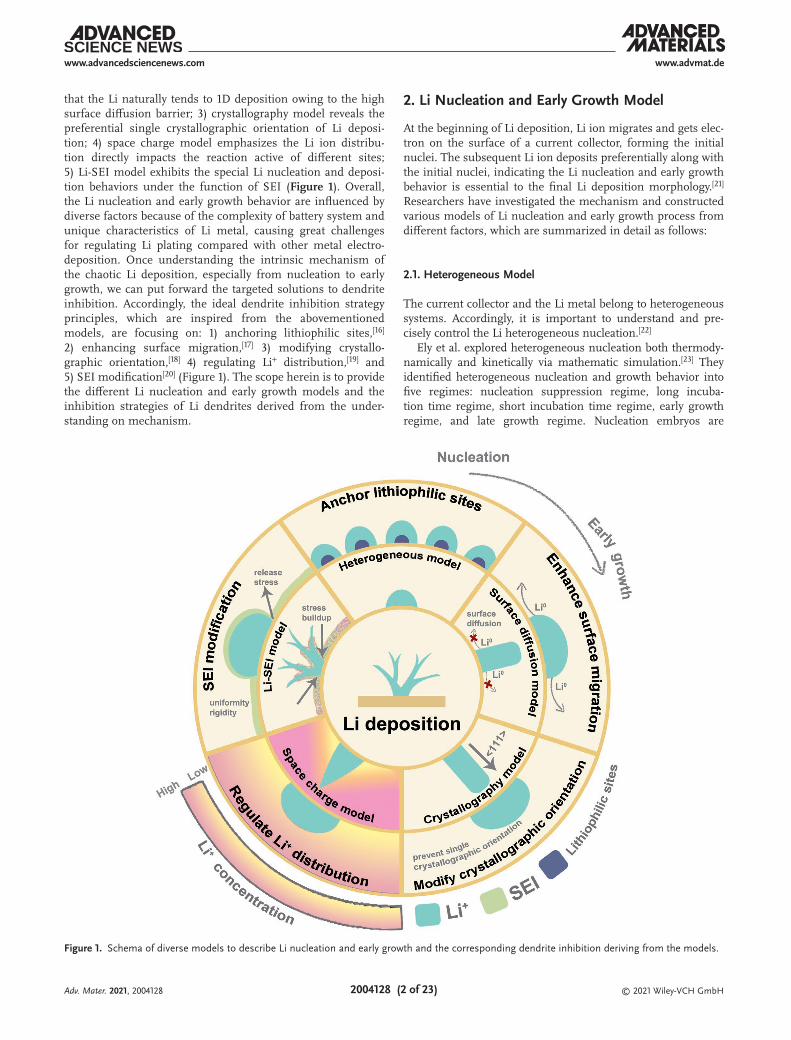
that the Li naturally tends to 1D deposition owing to the high surface diffusion barrier; 3) crystallography model reveals the preferential single crystallographic orientation of Li deposi-tion; 4) space charge model emphasizes the Li ion distribu-tion directly impacts the reaction active of different sites; 5) Li-SEI model exhibits the special Li nucleation and deposi-tion behaviors under the function of SEI (Figure 1). Overall, the Li nucleation and early growth behavior are influenced by diverse factors because of the complexity of battery system and unique characteristics of Li metal, causing great challenges for regulating Li plating compared with other metal electro-deposition. Once understanding the intrinsic mechanism of the chaotic Li deposition, especially from nucleation to early growth, we can put forward the targeted solutions to dendrite inhibition. Accordingly, the ideal dendrite inhibition strategy principles, which are inspired from the abovementioned models, are focusing on: 1) anchoring lithiophilic sites,[16] 2) enhancing surface migration,[17] 3) modifying crystallo-graphic orientation,[18] 4) regulating Li+ distribution,[19] and 5) SEI modification[20] (Figure 1). The scope herein is to provide the different Li nucleation and early growth models and the inhibition strategies of Li dendrites derived from the under-standing on mechanism.
2. Li Nucleation and Early Growth Model
At the beginning of Li deposition, Li ion migrates and gets elec-tron on the surface of a current collector, forming the initial nuclei. The subsequent Li ion deposits preferentially along with the initial nuclei, indicating the Li nucleation and early growth behavior is essential to the final Li deposition morphology.[21] Researchers have investigated the mechanism and constructed various models of Li nucleation and early growth process from different factors, which are summarized in detail as follows:
2.1. Heterogeneous Model
The current collector and the Li metal belong to heterogeneous systems. Accordingly, it is important to understand and pre-cisely control the Li heterogeneous nucleation.[22]
Ely et al. explored heterogeneous nucleation both thermody-namically and kinetically via mathematic simulation.[23] They identified heterogeneous nucleation and growth behavior into five regimes: nucleation suppression regime, long incuba-tion time regime, short incubation time regime, early growth regime, and late growth regime. Nucleation embryos are
Figure 1. Schema of diverse models to describe Li nucleation and early growth and the corresponding dendrite inhibition deriving from the models.
Adv. Mater. 2021, 2004128

© 2021 Wiley-VCH GmbH2004128 (3 of 23)
www.advmat.dewww.advancedsciencenews.com
thermodynamically unstable and easily disappear into the elec-trolyte in the nucleation suppression regime. The embryos subsequently coarsen under the Gibbs–Thomson interactions control during the long incubation time regime. Exceeding a critical regime, a short incubation time regime favors very tiny size distributions of nuclei. In the early and later growth regime, kinetically and thermodynamically stable nuclei grow into final form remaining constant growth rate. According to the analytical calculations of heterogeneous model, the den-dritic growth can be prevented through: 1) polishing the elec-trode surface with low roughness to lengthen the incubation period, 2) optimizing the anode particle size beneath the crit-ical thermodynamic radius, 3) controlling the plating potential below the critical value and a cycling frequency under the char-acteristic incubation frequency, and 4) improving the wetting nature (lithiophilicity, defined as the affinity of materials with Li species) of current collectors to Li deposition.
Inspired by the heterogeneous model, Chen et al. further enriched such model through investigating the lithiophilicity chemistry of heteroatom-doped carbon to render even het-erogeneous Li nucleation via first principles calculations and experimental characterization (Figure 2a).[24] Three key factors of electronegativity, the local dipole, and the charge transfer account for the lithiophilicity of heteroatom-doped carbon.
O doping and O and B co-doping exhibit the best lithiophi-licity among single-doped and co-doped carbons (Figure 2b,c), respectively. The lower nucleation overpotential and more uniform nucleation distribution in TEM images of O doped carbon frameworks further verify the excellent lithiophilicity of current collectors indeed promoting the superior nucleation. Heterogeneous model illuminates the Li nucleation behavior on the current collectors, which guides our design principle on Li hosts.[25]
2.2. Surface Diffusion Model
In contrast of Li metal batteries which form dendrite growth during cycling, some metals (such as Mg) based secondary bat-teries show no evidence of instability and disordered deposi-tion.[26] The comparison study of the deposition behavior of Li and Mg can deepen our understanding to inhibit the chaotic deposition. A density function theory (DFT) based study on Mg and Li plating at a vacuum/metal interface affirms the stronger MgMg bond than LiLi bond, which infers that unlike Li, Mg prefers to deposit high-dimensional structures rather than 1D dendritic whiskers.[27] Surface diffusion processes are also essential for the deposition behavior. Through the theoretical
Figure 2. a) Schematic illustration of the Li nucleation processes on conductive frameworks including absorption, the formation of Li bond, and charge transfer. b) Modeling of heteroatom-doped carbons. c) Summary of calculated binding energy between diverse heteroatom-doped carbons and Li atom. a–c) Reproduced with permission.[24] Copyright 2019, The Authors, published by American Association for the Advancement of Science.
Adv. Mater. 2021, 2004128

© 2021 Wiley-VCH GmbH2004128 (4 of 23)
www.advmat.dewww.advancedsciencenews.com
calculation of Li, Na, and Mg, Mg exhibits the lowest diffusion barriers and thus tend to the smooth surface growth.[28] Above all, the mobility of atoms at the interface significantly impacts if dendritic deposition or not. Reducing the surface diffusion barrier and enhancing the surface migration are useful for the uniform Li deposition.[29]
2.3. Crystallography Model
The conversion of Li ion to Li atom involves the nucleation and growth of crystal. The crystallographic orientation will dramatically impact the final deposition morphology. The Li metal dendrites with the body-centered cubic (BCC) crystal structure grow along preferentially the <111> direction (49% by number), followed by <211> (32%), and <211> (19%) as fac-eted, single-crystalline nanowires observed via cryo-electron microscopy (Figure 3a–d).[30] This deposition behavior can be elucidated by the {110} family of planes with the lowest energy surface[31] in the BCC crystal structure. Herein, a single-crystalline Li metal dendrite prefers facets exposing the {110} planes as the side surface. As shown in Figure 3e–g, the Li dendrite morphologies include triangular, hexagonal, and rectangular cross-sectional Li dendrite structures, respec-tively. Triangular and hexagonal cross section favor dendrites growing along <111>, because all three or six of the facets can expose {110} planes and therefore decrease the surface energy of Li deposition (Figure 3e,f and insets). The dendrite growing
along <111> in the TEM displays a hexagonal cross section, while the dendrite growing along <110> or <211>, whose side-walls cannot totally expose {110} facets, lengthening the rectan-gular cross section into the observed whisker structure in order to reduce their surface energy. Nevertheless, the morphology of Li deposition always demonstrates disordered structure not just the single-crystalline nanowires due to the presence of SEI on Li anode, which can be discussed in detail at the following section.
2.4. Space Charge Model
In 1990, Chazalviel proposed a space charge theory to interpret the Li nucleation and growth behavior.[32] This model is pre-sented in the dilute electrolytes in which the transport of ions just considers the mobility and diffusion coefficient without the electrolyte convection. During Li plating at fast rate, the con-centration of Li ion declines remarkably. The Li ion depletion on the surface of anode induces a huge space charge, resulting in the Li dendrite growth.
As Figure 4 shown, Chazalviel et al. calculated the ion con-centrations and electrostatic potential in a thin rectangular symmetrical cell. Region I (occurring in bulk electrolyte) and Region II (occurring on the surface of electrode and accounting for a tiny area around the electrode) are defined. In the Region II, there is an ion-depleted region near the electrode where the potential relatively declines, leading to a space charge ZceC0
Figure 3. a–c) Li metal dendrites and their corresponding SAED patterns (insets) growing along <111> (a), <110> (b), <211> (c). d) Statistics showing preferred growth direction. e–g) SEM images of triangular (e), hexagonal (f), and rectangular (g) cross-sectional structures for Li dendrites. a–g) Reproduced with permission.[30] Copyright 2017, The Authors, published by American Association for the Advancement of Science.
Adv. Mater. 2021, 2004128

© 2021 Wiley-VCH GmbH2004128 (5 of 23)
www.advmat.dewww.advancedsciencenews.com
and thus dendritic growth. According to the Chazalviel’s theory, dendrite growth starts at a time close to the Sand’s time[33] which describes that the concentration of cations drops to zero and the potential diverges. The Sand model is widely accepted to give a simple relationship between the Sand’s time and dif-fusion constant. Assuming the electrolyte is binary and intro-ducing the ambipolar diffusion constant, the Sand’s time was evaluated by Rosso et al. as follows[34]
τ π µ µµ
=
+
2
s0
2 2
DC eZ
Jc a c
a (1)
where τ is the time once Li dendrites starting to grow, D is dif-fusion coefficient, C0 is the initial concentration of cationic, Zc is the charge number of cations, μa and μc are the anionic and cationic mobility, J is effective electrode current density. This equation indicates that the following strategies, including lower effective local current density, higher Li salt concentration in the electrolyte and larger transference number of Li ion, con-tribute to dendrite inhibition, which is also verified experimen-tally in many research results.
2.5. Li SEI Model
The presence of SEI aggravates the complication of Li deposi-tion behavior compared with other metal deposition.[35] On the one hand, the SEI instantly forms above the surface of anode at the beginning of Li nucleation. The Li ions need to diffuse through SEI with higher diffusion barrier than electrolyte and convert to the metallic Li under the stress of SEI.[36] On the other hand, the fragile SEI will split open due to ununiform Li depo-sition causing local pressure increasing and expose the fresh Li which can react with electrolyte and form new weak SEI.[37] Chen et al. designed ingenious model experiments to control the rate-determining step through forming a series of SEI with different Li diffusion rate (through forming different amount of high ionic conductivity of SEI component) and altering the reaction rate (though changing the applied current density).[38] Consequently, they found that the diffusion-controlled process tended to dendritic Li deposition while the reaction-controlled process leaded to spherical Li deposition (Figure 5a,b). This observation can provide the helpful guidelines for tailoring the Li deposition through enhancing the ionic conductivity of SEI.
Not only the diffusion rate of SEI,[39] the stress under the SEI and the fracture of SEI significantly influence the Li depo-sition process.[40] Kushima et al.[41] introduced in situ environ-mental transmission electron microscopy (ETEM) observation of Li nucleation and early growth under the presence of SEI and separated the Li dendrite growth into the following stage (Figure 5c): 1) Spherical Li nucleus emerges at the surface and grows with its diameter proportional to square root of the time, which suggests that the process is diffusion limitation as the function of SEI layer. 2) The Li whisker grows from its root and pushes the initial deposition away from the electrode because the SEI at the root is thinner and therefore Li ion preferentially deposits at the root with higher diffusion rate. 3) The growth rate decreases due to thickening of SEI on the new Li depo-sition. 4) A kink is developed on the whisker dividing it into two segments under the accumulated stress under the SEI. The newly formed segment still grows from the root and pushes the preexisting portion of the whiskers remaining the same diameter. The influence of SEI fracture is further considered when establishing the Li nucleation and early growth models. Thirumalraj et al.[42] developed a Li-SEI model contemplating a 3D diffusion-controlled instantaneous process (J3D-DC)[43] with the synchronous reduction of electrolyte decomposition (JSEI) because of the SEI fracture to investigate the Li nucleation and early growth mechanism as follows
( ) ( ) ( )= +J t J t J ttotal 3D-DC SEI (2)
( )( )( )=
− + − − − −−
1 exp 1 exp 1
expa
tct d c t
gt
g (3)
where π
=∞
anF DC
, π πρ
=∞8
0c N DC M
, d n Fk C M2SEI SEI πρ
=∞
, g = N.
The Li-SEI model elicits the important kinetic parameters such as diffusion coefficient (D), number of nucleation sites (N0), and rate constant of electrolyte decomposition because
Figure 4. a) Scheme of the cell. b) Profile of the ion concentrations C and of the electrostatic potential V simulated by the space charge model in the hypothetical case of homogeneous deposition with negligible growth of the cathode. a,b) Reproduced with permission.[32] Copyright 1990, American Physical Society.
Adv. Mater. 2021, 2004128

© 2021 Wiley-VCH GmbH2004128 (6 of 23)
www.advmat.dewww.advancedsciencenews.com
of SEI fracture (kSEI) occurring during Li plating. Notably, JSEI enhances corresponding with time, suggesting that the JSEI deriving from the electrolyte decomposition raises with time as results of the SEI fracture during Li deposition. Besides, both D and kSEI increase as the overpotential, implying the more serious SEI fracture at higher overpotential (Figure 5d). More-over, several atomistic modeling works via molecular dynamics simulations are made to describe the Li growth behavior at the presence of SEI fracture.[44]
According to recent experimental and theoretical works, the structural uniformity[45] and mechanical strength[46] of SEI play the highly important role to directly influence Li ion diffu-sion and prevent the SEI fracture.[47] Specifically, the structural non-uniformity of SEI, including the different thicknesses in space and chemical inhomogeneity induced by complicated compound in the actual SEI, promptly disturbs the distribution of Li ion flux.[48] While the SEI with low mechanical strength will break easily when the fluctuation of anode surface occurs due to the ununiform Li+ distribution and the subsequent spot accumulation.[49] The fresh Li metal subsequently exposes through the cracks where the competitive reaction between both electrolyte deposition and lithium dendrite growth can
occur immediately due to the thermodynamic activity of Li metal (Figure 6a). Figuring out the dominant factors for the failure of SEI can enhance our understanding to rational design the practical SEI for dendrite inhibition. Shen et al. described the influence of structural uniformity and mechanical strength through an electrochemical-mechanical model (coupling stress, diffusion, electric fields, and electrochemical reactions) via the finite-element method (FEM) (Figure 6b).[50] The structural uniformity is the most important factor to stabilize the SEI, while the strength modulus is very serviceable just under about 3.0 GPa with a low current density (Figure 6c). Summarily, the Li-SEI model deepens our understanding on SEI design with structural uniformity, high diffusion coefficient and appropriate mechanical strength for dendrite-free LMBs.
To sum up, we have summarized insightful models, which focus on diverse aspects (such as Li+ distribution on surface of anode, crystal orientation, and the function of SEI), to describe Li nucleation and early growth from the nature of the Li deposi-tion. Actually, the external conditions in effecting the Li nuclea-tion and early growth are also explored, including the applied external pressure, current density, and temperature. The higher applied external pressure (≈850 kPa) can destroy the dominant
Figure 5. a) The diffusion and reaction steps synergistically effect the Li ion concentration beneath the SEI. Fast reaction rate and slow diffusion rate lead to fast Li+ consumption and thus low concentration of Li+ beneath the SEI, while slow reaction rate and fast diffusion rate result in high concentra-tion of Li+. b) The Li+ concentration beneath the SEI obviously influence the Li deposition morphology. a,b) Reproduced with permission.[38] Copyright 2020, Wiley-VCH. c) Schematic illustration of mechanism of Li whisker growth under the SEI. Reproduced with permission.[41] Copyright 2017, Elsevier. d) Schematic diagram of nucleation and growth of Li metal with SEI fracture during Li deposition on Cu foil at different potentials. Reproduced with permission.[42] Copyright 2019, American Chemical Society.
Adv. Mater. 2021, 2004128

© 2021 Wiley-VCH GmbH2004128 (7 of 23)
www.advmat.dewww.advancedsciencenews.com
crystal orientation of Li, leading to 2D electroplating of Li.[51] The current density and temperature are reported to impact the Li nucleus size and shape.[52] Above external condition will influence the Li nucleation and early growth process both ther-modynamically and kinetically and thus effect the final Li depo-sition morphology.
3. Dendrite Inhibition Strategies
3.1. Anchoring Lithiophilic Sites for Uniform Nucleation
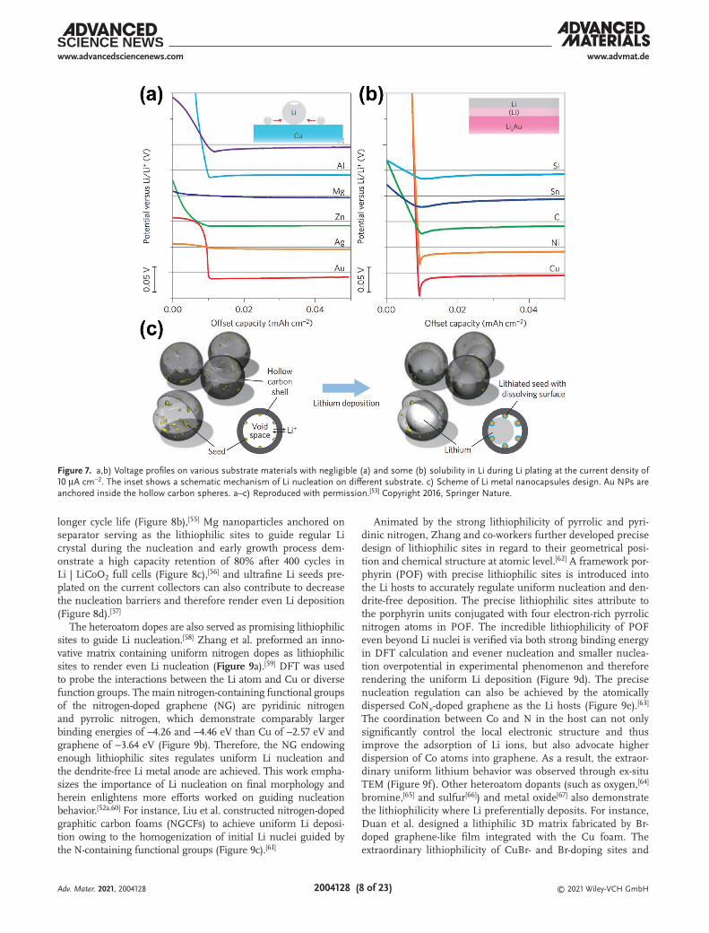
As a similar concept of hydrophilia, lithiophilicity is defined as the affinity of Li species with host materials, which was first raised by Cui and co-workers and then attracted worldwide attention.[53] They studied series of 11 elemental substrate mate-rials: Au, Ag Zn, Al, Pt, Mg, Si, Sn, C, Ni, and Cu. Cu foil is a common current collector for anode and some metals (Cu and Ni) cannot react with Li while others can form an alloy phase with Li. The overpotential between the two electrodes in the first galvanostatic deposition of Li metal is divided charge transfer overpotential, mass-transfer overpotential, reaction overpotential, and nucleation overpotential. The nucleation overpotential, which exists only in the transitory nucleation stage at the initial Li deposition, is employed to evaluate the lithiophilicity of materials. As shown in Figure 7a, Cu, Ni, C,
Sn, and Si substrates display clear nucleation overpotential. For Cu and Ni, the huge nucleation overpotential comes from the large thermodynamic mismatch between Li and substrate. Even though C, Sn, and Si substrates can form alloy with Li, the alloy compound contains a high percentage of Li, whose crystal structure still differs from the Li. Hence, the nucleation bar-rier also needs to be overcame on abovementioned substrate. While Au, Ag, Zn, and Mg substrates exhibit zero nucleation overpotential after fully lithiated, effectively eliminating nuclea-tion barriers (Figure 7b). Consequently, above metals can be adopted as lithiophilic sites for Li preferentially nucleating to regulate uniform nucleation and even subsequently growth. The principle of Li metal nucleation guided Cui and co-workers constructed a nano-capsuled anode composed by hollow carbon spheres with nanoparticle Au seeds inside (Figure 7c). Selec-tive deposition, where lithium metal chiefly grows inside the hollow carbon spheres under the function of Au seeds, prevents Li dendrite growth and exhibits high CE of 98% for more than 300 cycles. Inspired by above-mentioned strategies, Ag nano-wires assembled on interconnected 3D graphene skeletons reg-ulate uniform Li deposition and renders long-lifespan half cells and LiNi0.5Co0.2Mn0.3O2 (NCM523) full cells (Figure 8a),[54] Zn clusters homogeneously confined and dispersed in carbonized metal–organic frameworks are acted as uniform lithiophilic sites to guide Li deposition and therefore exhibit superior elec-trochemical performance with ultralow potential hysteresis and
Figure 6. a) Scheme of the morphology evolution in LMBs with a nonuniform SEI. Cracks and distortions of SEI under low and high mechanical strength, severally. b) Schematic diagram and calculated field distribution of the Li | Li symmetric cell. c) Failure time corresponds with different ESEI and pd, where tfmax represents the maximum failure time under each pd (representing the nonuniformity). a–c) Reproduced with permission.[50] Copyright 2020, Wiley-VCH.
Adv. Mater. 2021, 2004128
© 2021 Wiley-VCH GmbH2004128 (8 of 23)
www.advmat.dewww.advancedsciencenews.com
longer cycle life (Figure 8b),[55] Mg nanoparticles anchored on separator serving as the lithiophilic sites to guide regular Li crystal during the nucleation and early growth process dem-onstrate a high capacity retention of 80% after 400 cycles in Li | LiCoO2 full cells (Figure 8c),[56] and ultrafine Li seeds pre-plated on the current collectors can also contribute to decrease the nucleation barriers and therefore render even Li deposition (Figure 8d).[57]
The heteroatom dopes are also served as promising lithiophilic sites to guide Li nucleation.[58] Zhang et al. preformed an inno-vative matrix containing uniform nitrogen dopes as lithiophilic sites to render even Li nucleation (Figure 9a).[59] DFT was used to probe the interactions between the Li atom and Cu or diverse function groups. The main nitrogen-containing functional groups of the nitrogen-doped graphene (NG) are pyridinic nitrogen and pyrrolic nitrogen, which demonstrate comparably larger binding energies of −4.26 and −4.46 eV than Cu of −2.57 eV and graphene of −3.64 eV (Figure 9b). Therefore, the NG endowing enough lithiophilic sites regulates uniform Li nucleation and the dendrite-free Li metal anode are achieved. This work empha-sizes the importance of Li nucleation on final morphology and herein enlightens more efforts worked on guiding nucleation behavior.[52a,60] For instance, Liu et al. constructed nitrogen-doped graphitic carbon foams (NGCFs) to achieve uniform Li deposi-tion owing to the homogenization of initial Li nuclei guided by the N-containing functional groups (Figure 9c).[61]
Animated by the strong lithiophilicity of pyrrolic and pyri-dinic nitrogen, Zhang and co-workers further developed precise design of lithiophilic sites in regard to their geometrical posi-tion and chemical structure at atomic level.[62] A framework por-phyrin (POF) with precise lithiophilic sites is introduced into the Li hosts to accurately regulate uniform nucleation and den-drite-free deposition. The precise lithiophilic sites attribute to the porphyrin units conjugated with four electron-rich pyrrolic nitrogen atoms in POF. The incredible lithiophilicity of POF even beyond Li nuclei is verified via both strong binding energy in DFT calculation and evener nucleation and smaller nuclea-tion overpotential in experimental phenomenon and therefore rendering the uniform Li deposition (Figure 9d). The precise nucleation regulation can also be achieved by the atomically dispersed CoNx-doped graphene as the Li hosts (Figure 9e).[63] The coordination between Co and N in the host can not only significantly control the local electronic structure and thus improve the adsorption of Li ions, but also advocate higher dispersion of Co atoms into graphene. As a result, the extraor-dinary uniform lithium behavior was observed through ex-situ TEM (Figure 9f). Other heteroatom dopants (such as oxygen,[64] bromine,[65] and sulfur[66]) and metal oxide[67] also demonstrate the lithiophilicity where Li preferentially deposits. For instance, Duan et al. designed a lithiphilic 3D matrix fabricated by Br-doped graphene-like film integrated with the Cu foam. The extraordinary lithiophilicity of CuBr- and Br-doping sites and
Figure 7. a,b) Voltage profiles on various substrate materials with negligible (a) and some (b) solubility in Li during Li plating at the current density of 10 µA cm−2. The inset shows a schematic mechanism of Li nucleation on different substrate. c) Scheme of Li metal nanocapsules design. Au NPs are anchored inside the hollow carbon spheres. a–c) Reproduced with permission.[53] Copyright 2016, Springer Nature.
Adv. Mater. 2021, 2004128

© 2021 Wiley-VCH GmbH2004128 (9 of 23)
www.advmat.dewww.advancedsciencenews.com
the low Li diffusion barrier on the anode surface of generated LiBr lead to pancake-like Li seeds and growth and improve elec-trochemical performance.[65]
However, unlimited increase of the amount of lithiophilic sites in the Li hosts inevitably causes side effects which are harmful for Li plating. Specifically, introducing the abovemen-tioned insulating lithiophilic species via material composi-tion or heteroatom doping decreases the integral conductance of Li hosts. The excessive insulating lithiophilic species will hinder electron conduction during charge/discharge process and in reverse aggravate Li dendrite growth. Herein, Chen et al. systematically explored the synergistic effect of lithiophi-licity and conductance for rational design of Li hosts to realize
dendrite-free Li metal anode.[68] Considering the liphiophilicity on 2D scale is not enough but also including the vertical distri-bution of lithiophilicity on integral anode. Gradient-distribution of nucleation seeds on Li hosts are further designed to better render controllable Li deposition.[69]
According to extensive research, it is undeniable that anchoring lithiophilic sites can efficiently render homogenous nucleation and thus dendrite-free Li deposition since the nucleation process plays a very important role for the final deposition.[60c,70] How-ever, the subsequent deposition process also notably impacts the following deposition behavior during repeated cyclings. Herein, anchoring the lithiophilic sites need to synergy with other methods to control the integral deposition process.[71]
Figure 8. a–d) Schematic illustrations of the uniform Li nucleation and plating behaviors: a) under the function of Ag nanowires; b) on a carbonized MOF with Zn clusters; c) with Mg nanoparticles on the separator; and d) on the uniform Li seed layer. a) Reproduced with permission.[54] Copyright 2018, Wiley-VCH. b) Reproduced with permission.[55] Copyright 2018, Wiley-VCH. c) Reproduced with permission.[56] Copyright 2019, Elsevier. d) Reproduced with permission.[57] Copyright 2019, Elsevier.
Adv. Mater. 2021, 2004128

© 2021 Wiley-VCH GmbH2004128 (10 of 23)
www.advmat.dewww.advancedsciencenews.com
Figure 9. a) Scheme of the Li nucleation and subsequent plating process on NG electrode and Cu foil electrode. b) Binding energy of a Li atom with Cu, graphene, and different functional groups of NG. c–e) Schematic diagrams of Li nucleation on NGCF (c), Li host with strong lithiophilicity (d), and CoNx material and preferential Li nucleation sites (e). The carbon, nitrogen, and cobalt are marked in gray, blue, and deep pink, respectively. f) TEM image of Li nucleation sites on CoNx at 0.1 mA cm−2 for 5 min. a,b) Reproduced with permission.[59] Copyright 2017, Wiley-VCH. c) Reproduced with permission.[61] Copyright 2018, Wiley-VCH. d) Reproduced under the terms of the CC-BY Creative Commons Attribution 4.0 International license (https://creativecommons.org/licenses/by/4.0).[62] Copyright 2019, The Authors, published by Science and Technology Review Publishing House. e,f) Reproduced with permission.[63] Copyright 2019, Wiley-VCH.
Adv. Mater. 2021, 2004128
© 2021 Wiley-VCH GmbH2004128 (11 of 23)
www.advmat.dewww.advancedsciencenews.com
3.2. Enhancing Surface Migration
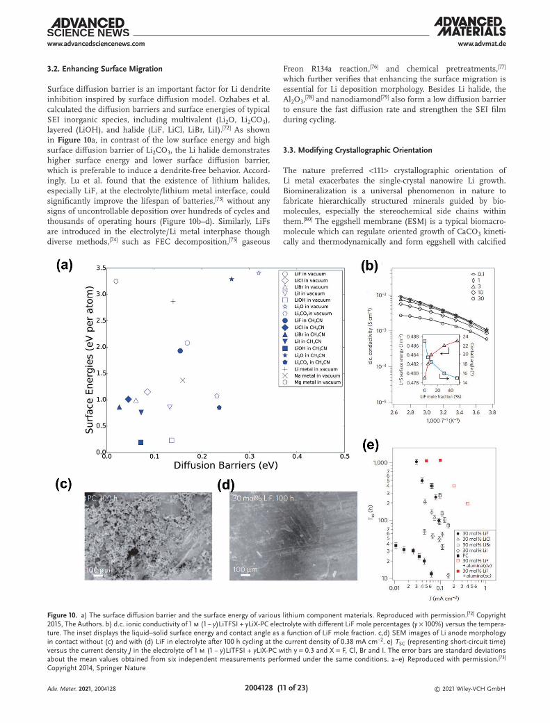
Surface diffusion barrier is an important factor for Li dendrite inhibition inspired by surface diffusion model. Ozhabes et al. calculated the diffusion barriers and surface energies of typical SEI inorganic species, including multivalent (Li2O, Li2CO3), layered (LiOH), and halide (LiF, LiCl, LiBr, LiI).[72] As shown in Figure 10a, in contrast of the low surface energy and high surface diffusion barrier of Li2CO3, the Li halide demonstrates higher surface energy and lower surface diffusion barrier, which is preferable to induce a dendrite-free behavior. Accord-ingly, Lu et al. found that the existence of lithium halides, especially LiF, at the electrolyte/lithium metal interface, could significantly improve the lifespan of batteries,[73] without any signs of uncontrollable deposition over hundreds of cycles and thousands of operating hours (Figure 10b–d). Similarly, LiFs are introduced in the electrolyte/Li metal interphase though diverse methods,[74] such as FEC decomposition,[75] gaseous
Freon R134a reaction,[76] and chemical pretreatments,[77] which further verifies that enhancing the surface migration is essential for Li deposition morphology. Besides Li halide, the Al2O3,[78] and nanodiamond[79] also form a low diffusion barrier to ensure the fast diffusion rate and strengthen the SEI film during cycling.
3.3. Modifying Crystallographic Orientation
The nature preferred <111> crystallographic orientation of Li metal exacerbates the single-crystal nanowire Li growth. Biomineralization is a universal phenomenon in nature to fabricate hierarchically structured minerals guided by bio-molecules, especially the stereochemical side chains within them.[80] The eggshell membrane (ESM) is a typical biomacro-molecule which can regulate oriented growth of CaCO3 kineti-cally and thermodynamically and form eggshell with calcified
Figure 10. a) The surface diffusion barrier and the surface energy of various lithium component materials. Reproduced with permission.[72] Copyright 2015, The Authors. b) d.c. ionic conductivity of 1 m (1 − y)LiTFSI + yLiX-PC electrolyte with different LiF mole percentages (y × 100%) versus the tempera-ture. The inset displays the liquid–solid surface energy and contact angle as a function of LiF mole fraction. c,d) SEM images of Li anode morphology in contact without (c) and with (d) LiF in electrolyte after 100 h cycling at the current density of 0.38 mA cm−2. e) TSC (representing short-circuit time) versus the current density J in the electrolyte of 1 m (1 − y)LiTFSI + yLiX-PC with y = 0.3 and X = F, Cl, Br and I. The error bars are standard deviations about the mean values obtained from six independent measurements performed under the same conditions. a–e) Reproduced with permission.[73] Copyright 2014, Springer Nature
Adv. Mater. 2021, 2004128

© 2021 Wiley-VCH GmbH2004128 (12 of 23)
www.advmat.dewww.advancedsciencenews.com
crystallization. Accordingly, the trifluoroethanol-modified ESM (TESM) is employed effectively to regulate orientation deposi-tion through cryo-TEM.[18] The high-resolution TEM (HRTEM) images of Li microsphere deposited with the function of TESM from the [001] zone axis direction demonstrates a lattice spacing of 2.48 Å, which matches properly with the {110} planes of Li (Figure 11a–c). As shown in Figure 10d–f, Li also nucleates from {211} planes. The atomic observation clearly confirms the typical dendritic growth along the <111> direction is sup-pressed while the Li microspheres grow predominantly along the <110> and <211> direction under the function of TESM. The controlled Li deposition morphology therefore promotes out-standing electrochemical performance. When paired with LFP cathode, full cells with TESM demonstrate improved cycling stability even with high loading of LFP of 3 mAh cm−2 and a low N/P ratio of 3.3 (Figure 11g).
3.4. Regulating the Li Ion Distribution
A lot of previous experimental and theoretical works substan-tiate that the rapid depletion of Li ion on the anode surface induces the Li ion preferentially reaction on the tip of initial nucleation with relative more Li ions under the dual function of electric and concentration fields.[81] Consequently, it is of sig-nificance to inhibit the Li dendrite growth by maintaining the Li ion supplication via enhancing the C0 and t+ and artificial regulation of Li ion distribution on the surface of anode.
The battery electrolyte concentrations of around 1.0 m are adopted generally due to the highest ionic conductivity of the electrolyte at this concentration. However, the Li deposition at a high current density will exhaust the quantities of Li ions avail-able for obtaining electrons on the anode surface. Increasing the Li ion concentration can obviously alleviate the Li ion
Figure 11. a,d) Cryo-TEM images of Li deposition in the existence of TESM. b,e) The corresponding HRTEM images of marked area in (a) and (d) along the [001] and [111] zone axes, respectively. c,f) The measured lattice spacing in (b) and (e), severally. g) Cycling performance of Li | LFP full cells with a capacity ratio of N/P ratio around 3.3 at 1 C (1 C = 170 mA g−1). a–g) Reproduced under the terms of the CC-BY Creative Commons Attribution 4.0 International license (https://creativecommons.org/licenses/4.0).[18] Copyright 2020, The Authors, published by Springer Nature.
Adv. Mater. 2021, 2004128

© 2021 Wiley-VCH GmbH2004128 (13 of 23)
www.advmat.dewww.advancedsciencenews.com
storage. Generally, unlimited increasing the concentration of Li salts apparently results in the decline of ionic conductivity and the increase of viscosity in electrolyte (Figure 12a). Neverthe-less, various unusual functionalities, including high reductive stability, high oxidative stability, Al anti-corrosion, high thermal stability, high carrier density, fast electrode reaction, low vola-tility, and low polysulfide dissolution, have been discovered at highly concentrated electrolytes (HCEs),[82] thus attracting much attention recently.[83] Qian et al.[84] utilized the HCEs con-sisted by ether solvents and the salt lithium bis(fluorosulfonyl)imide (LiFSI or LiN(SO2F)2) to achieve dendrite-free Li anode (Figure 12b,c). The superior performance of HCEs attributes to not only increasing the high Li+ on the surface of anode, but also improving the reductive stability of electrolyte owing to shortage of available reactive solvent and sacrificial anion (Figure 12d). Unfortunately, their practical applications are obstructed by the high viscosity, the poor wettability on elec-trodes and separators, and the high material costs. To further
address these issues, many efforts have been took to develop a new class of localized high-concentration electrolytes (LHCEs) by adding a diluent (such as bis(2,2,2-trifluoroethyl)ether (BTFE),[85] hydrofluoroether (HFE),[86] tris (2,2,2-trifluoroethyl)orthoformate (TFEO)[87] in the HCEs. After dilution, the con-centration of Li+ deceases. Accordingly, the LHCEs can over-come the abovementioned challenges associated with HCEs, while cannot sacrifice the high CE and dendrite-free behavior.
Low cation transference number (t+) of electrolyte induces a large Li+ concentration gradient on the surface of anode, thus causing huge space charge and Li dendrite growth according to the space charge model.[88] Herein, engineering the electrolyte with high t+ provides attractive candidates for increasing the safety and lifespan of LMBs.[89]
Immobilizing anions in the electrolyte is widely adopted to contribute to enhance the t+ and therefore stable electrodepo-sition from many recent works.[90] Concretely, a flexible anion-immobilized solid-state composite electrolyte synthesized by a
Figure 12. a) Typical ionic conductivity curve in aprotic solvent mixture with different concentration of Li salt. Reproduced with permission.[82] Copyright 2015, The Authors, published by ECS. b,c) SEM images of Li deposition morphology on Cu foils at the current density of 1.0 mA cm−2 after 1.5 h in the electrolyte of 1 m LiPF6-PC (b) and 4 m LiFSI-DME (c). The insets show Cu foils after Li deposition with the diameter of 2 cm. d) Cyclic voltammograms of Li plating/stripping in different electrolytes adopting Pt disk as the working electrode and a Li metal as reference and counter electrode. The scale rate was 50 mV s−1. b–d) Reproduced under the terms of the CC-BY Creative Commons Attribution 4.0 International license (https://creativecommons.org/licenses/by/4.0).[84] Copyright 2015, Springer Nature.
Adv. Mater. 2021, 2004128

© 2021 Wiley-VCH GmbH2004128 (14 of 23)
www.advmat.dewww.advancedsciencenews.com
poly(ethylene oxide) (PEO)–lithium bis(trifluoromethylsulphonyl)imide (LiTFSI)–LLZTO (PLL) filled with garnet-type Al-doped Li6.75La3Zr1.75Ta0.25O12 (LLZTO) ceramic particles was designed to protect Li metal anodes.[91] The crystallization of PEO is dra-matically reduced and anions are effectively immobilized owing to their interactions with ceramic particles and polymer matrix (Figure 13a). As Figure 13b shows, the PLL composite electro-lyte with 40% LLZTO exhibits a high t+ of 0.58, significantly enhancing than typical carbonate and ether electrolyte.
Single- or near-single-ion conducting electrolyte based on Nafion and ceramics are widely recognized as promising alter-natives owing to their thermal and chemical stability and outstanding mechanical strength.[92] Specifically, Xu et al.[93] con-structed an artificial dual-phase single-ion-conducting interface (donated as LLN) containing soft lithiated Nafion components and rigid garnet Al-doped LLZTO (Figure 13c). Both lithiated Nafion and garnet Al-doped LLZTO not only exhibit the single-ion-conducting but ultrahigh chemical and electrochemical sta-bility,[94] which endow the LLN with high t+ of 0.82. Besides, the bottom layer of garnet Al-doped LLZTO sustains the high mechanical rigidity while the top layer of Li–Nafion maintains the noticeable flexibility, synergistically building an “internal-rigid” and “outer-flexible” layer to tolerate the dramatic fluctua-tion of Li metal anode during continuous Li plating/stripping. Therefore, the Li anode protected by LLN can remain a relatively compact morphology after long-time cycling, in contrast of thick mussy Li accumulated on the bare Li. The ultrathin Li | LFP full cell protected by LLN displays a stable a higher capacity retention of 87.4% after 150 cycles (Figure 13d). Above rationally designed dual-layer layer maximizes the function of single-ion conducting garnet LLZTO and Nafion to inhibit Li dendrite growth. Gen-erally, the single-ion conducting electrolyte naturally provides a high efficiency ion channels and uniform distribution of Li ions, leading to controllable Li deposition.
Artificial regulation of Li ion distribution is another impor-tant method to directly control the ion distribution on the sur-face of anode. Cs+ can absorb on the tip of initial nucleation while cannot be reduced due to its equilibrium potential lower than Li+ deposition potential (Figure 14a).[95] Moreover, the repulsion between Li+ and Cs+ pushes the Li+ distributes at the concaves and therefore fills up the surface of Li anode. Inte-grated electrode design strategies are further proposed to artifi-cial regulation ion distribution. 3D glass fiber (GF) cloths with large amount of polar functional groups (SiO, OH, OB) are utilized.[96] The interfacial interaction between Li ions and GF cloths (modeled as quartz SiO2 (110)) is explored through a computational perspective based on DFT. Compared plane of Cu (111) and step site on Cu (111), the SiO2 demonstrates the highest binding energy of 3.99 eV. Such strong interaction drives Li ion absorbed by GF cloths. FEM simulation is fur-ther adopted to describe the distribution of Li ion on 2D Cu foil with/without GF cloths. Consequently, the Li ions near the bumps on Cu foil are uniformly distributed owing to the strong interactions between Li ions and GF cloths (Figure 14b). Besides the utilization of chemical force,[97] External physical force is another key factor in homogenizing Li ion.[98] Intro-ducing Lorentz force (Figure 14c)[99] and ultrasonic waves (Figure 14d)[100] during the deposition process have been also confirmed to modulate even Li ion distribution. The abovemen-tioned artificial strategies prove to guide the Li ion distribution and therefore prevent the Li dendrite growth.
3.5. SEI Modification: Fast Li+ Diffusion Rate, Stress-Release, Mechanical Strength, and Structural Uniformity
The ionic conductivity of SEI is several orders of magnitude lower than of the liquid electrolyte, so the Li+ diffusion through the SEI
Figure 13. a) Schematic diagram of the Li deposition behavior of the Li metal anode protected by the PLL solid electrolyte with immobilized anions. b) t+ of PLL composite electrolyte, PEO-LiTFSI solid electrolyte, 1 m LiPF6-EC/DEC, and 1 m LiTFSI-DOL/DME liquid electrolyte. a,b) Adapted with permission.[91] Copyright 2017, National Academy of Sciences c) Schematic illustration of the single-ion-conducting LLN consisted of rigid LLZTO and elastic Li–Nafion. d) Cycling performance of Li | LFP cells with bare Li and LLN-coated Li at 1 C rate. c,d) Reproduced with permission.[93] Copyright 2019, Wiley-VCH.
Adv. Mater. 2021, 2004128

© 2021 Wiley-VCH GmbH2004128 (15 of 23)
www.advmat.dewww.advancedsciencenews.com
is the rate-determining step of Li+ diffusion process. Enhancing the amount of higher ionic conductivity of the SEI compo-nents (Li2S/Li2Se,[101] Li3N,[102] LiI,[103] Li3PS4,[104] and Li2TeS3
[105]) can maintain the Li deposition under the reaction-controlled
condition and therefore regulating the compact Li deposition morphology. Liu et al. employed a Li+ conductive Li2S/Li2Se pro-tection layer to protect Li anode with a dendrite-free deposition behavior over 900 h.[101] Liang and co-workers fabricated a Li7P2S8I
Figure 14. a,b) Schematic diagrams of Li nucleation and subsequent deposition process based on the self-healing electrostatic shield mechanism (a), and on a GF-modified Cu foil electrode (b). c,d) Schemes of Li ion distribution under the function of Lorentz force (c), and ultrasonic waves (d). a) Reproduced with permission.[95] Copyright 2013, American Chemical Society. b) Reproduced with permission.[96] Copyright 2016, Wiley-VCH. c) Reproduced with permission.[99] Copyright 2019, Wiley-VCH. d) Reproduced with permission.[100] Copyright 2020, Wiley-VCH.
Adv. Mater. 2021, 2004128

© 2021 Wiley-VCH GmbH2004128 (16 of 23)
www.advmat.dewww.advancedsciencenews.com
from LiI and Li3PS4, which demonstrated electrochemical sta-bility up to 10 V versus Li/Li+ and rapid ion conduction.[106]
Under the function of SEI, accumulated stress of Li metal anode beneath the SEI drives the Li to deposit the Li whisker pref-erentially occurring on the sites where the SEIs are thin or even defective. It is logical to release or control the local stress beneath the SEI. Wang et al.[40b] found that the Li plating on the Cu current collectors supported by soft substrate demonstrated 2D wrinkle patterns owing to the stress relief mechanism (Figure 15a) and
revealed the function of compressive stress in Li dendrite forma-tion through a stress-driven dendrite growth model, which was postulated by the following factors: 1) plating-induced compres-sive stress, 2) surface passivation by the SEI, 3) the presence of subsurface planar defects, 4) the extremely high room-tempera-ture diffusivity of Li (Figure 15b,c). The rate of filament growth is given by vfilament = JVLi/π r2, where VLi is the molar volume of Li and the r is the filament radius, which can be measured though SEM images under different substrates (Figure 15d). The critical
Figure 15. a) Cu foil wrinkling during Li deposition and dendrite inhibition via using soft substrate. b) Schematic illustration of the stress-driven Li den-drite growth mechanism. The stress-driven Li migration to the base of a fresh deposited shallow surface grain, which grows into a whisker. d) Geometry of a Li filament growing from a surface crack considering the filament growth rate calculation. e) The grow rate of filament Vfilament as the function of grain opening angle θ for compressive residual stress σ = 100 and 2.3 MPa. The green line demonstrates the average Li plating rate Vplating = 1.3 nm s−1 at the current density of 1 mA cm−2. a–e) Reproduced with permission.[40b] Copyright 2018, Springer Nature.
Adv. Mater. 2021, 2004128

© 2021 Wiley-VCH GmbH2004128 (17 of 23)
www.advmat.dewww.advancedsciencenews.com
condition for dendrite growth is vfilament > vplating (vplating = JVLi/F). The calculated vfilament and vplating results are shown in Figure 14e, where the vfilament is much larger than vplating on hard Cu foils (θ = 100 MPa) while vfilament is less than vplating on soft substrates (θ = 2.3 MPa), corresponding the dendrite morphology on hard Cu foils while 2D wrinkle patterns on soft substrates. Therefore, they designed a 3D soft scaffold under the guidance of the stress relaxation mechanism on Li metal anode, which exhibited expect-able electrochemical performance in LFP full cell.
Enhancing the mechanical strength of SEI is also consid-ered to control the stress and tolerate the lithium dendrite growth.[107] The artificial SEI composed of polymer,[108] inor-ganic ceramics,[109] and their hybrids[110] is utilized to enhance its mechanical strength.[111] However, in the section 2.5, the high mechanical strength of SEIs have limited effects on den-drite inhibition, which could be also proved in Zhao et al.’s work.[112] They compared the Al2O3 composite separator with the Young’s modulus of 9.60 GPa and LLZTO composite sepa-rator with Young’s modulus of 2.08 GPa and found the LLZTO demonstrated better electrochemical performance. Beside the enough mechanical strength, the LLZTO acts as redis-tributors to dredge the crowded Li ions and renders the ions uniform deposition under the commercial porous PP separa-tors (Figure 16a), which can be brilliantly confirmed via the simulation of Li+ migration (Figure 16b) and Li deposition morphology (Figure 16c). Furthermore, the Li | LFP pouch cell
exhibits a superior specific capacity of above 140 mAh g−1 and remains 88% capacity retention over 90 cycles (Figure 16d).
The intrinsic uniformity of SEI play a very important role on dendrite inhibition through theoretical research. The essential uniformity and the constant complements of building blocks of SEIs collectively contribute to sustainable SEIs for practical con-ditions.[113] Specifically, rational combination of LiF-rich SEI and LiNxOy-contained SEI, which are widely assumed as the admi-rable strategies to protect the Li anode under mild conditions, to design the sustainable fluorinated-nitrided SEI (FN-SEI) was promoted under the practical batteries (Figure 17a) assem-bled with a high loading NCM523 cathode (4.4 mAh cm−2), a ultrathin Li anode (33 µm), and lean electrolytes (6.1 g Ah−1). The adequate heterogeneous grain boundaries among LiF, LiNxOy, and Li2O, which dominate in the components of FN-SEI, dem-onstrate clear spatial distributions vertically, leading to uni-form and rapid Li deposition. As a result, the FN-SEI in rigor practical Li | NCM523 cell afford to a capacity retention of 83% after 150 cycles in contrast of 4 cycles protected by pristine SEI (Figure 17b). Considering thoroughly the SEI factor of mechan-ical strength, Li diffusion rate, and structural uniformity, Li et al.[114] designed an artificial composite SEI incorporating MnO2 nanosheets with mechanical strength and high diffusion rate uniformly distributed in PEO (Figure 17c). Xu et al.[115] ration-ally hybridized an artificial protective layer (denoted as APL) composed by poly(vinylidene fluoride-hexafluoro propylene)
Figure 16. a) Schematic illustration of Li deposition behavior adopting a composite separator with the LLZTO layers as an ion redistributor to render even Li ion distribution. b) Ion transportation behaviors in the composite separators with the LLZTO layers as an ion redistributor. c) SEM image of dendrite-free deposition behavior on the Li metal anode with a composite separator. d) Cycling performance of practical pouch cells at 0.1 C. a–d) Reproduced with permission.[112] Copyright 2018, The Authors, published by American Association for the Advancement of Science.
Adv. Mater. 2021, 2004128

© 2021 Wiley-VCH GmbH2004128 (18 of 23)
www.advmat.dewww.advancedsciencenews.com
(PVDF-HFP) and LiF particle. The APL demonstrates high mechanical modulus, superb shape compliance, and high ionic conductivity. (Figure 17d). With an APL-protected LMA, Li | LFP full cells display 2.5 times longer lifespan compared with bare Li anode and high CEs.
To sum up, the presence of SEI makes the Li deposition process completely differ from other metal (such as Cu, Cr, Fe, Au, and Ag) in the electroplating industry. Although there are SEIs definitely between the Li anode and electrolyte owing to the ultralow electrochemical potential and high exchange cur-rent of Li metal, SEI modification emerges as an indispen-sable and promising strategy to regulation Li nucleation and deposition. Through fundamental understanding and experi-mental research on SEI above, the SEI-modification principle can follow (Figure 18): 1) fast Li+ diffusion rate to guide Li deposition process under the reaction-controlled condition; 2) releasing compressive stress[116] and 3) releasing enough
mechanical strength[117] of SEI to hinder SEI cracking due to the accumulated pressure under the SEI; and 4) uniform enough to maintain the homogeneous Li+ diffusion through SEI.
4. Conclusions and Perspective
Undoubtedly, next-generation high-energy-density batteries rep-resented by LMBs will play a vital role in the fourth industrial revolution according to the wide high-energy-density demands brought by the Internet of Things. Disordered Li deposition dramatically hinders the practical use of LMBs. Understanding the Li deposition, especially from nucleation to early growth, is an essential step to prevent the Li dendrite growth. Though the researchers’ arduous efforts, the different models, including the heterogeneous model, surface diffusion model, crystallography model, space charge model and Li-SEI model are raised to
Figure 17. a) Comparison between practical and mild conditions in a coin cell. b) Cycling performance of Li | NCM523 full cells with different SEIs at 0.4 C after two cycles at 0.1 C. a,b) Reproduced with permission.[113] Copyright 2020, Wiley-VCH. c) Scheme of the artificial SEI composed of a PEO/LiTFSI/MnO2. Reproduced with permission.[114] Copyright 2020, Royal Society of Chemistry. d) Schematic diagram of Li deposition behavior with APL which is conformal and mechanically strong to prevent Li dendrite growth. Reproduced with permission.[115] Copyright 2018, Wiley-VCH.
Figure 18. Schematic illustration of Li deposition behavior before and after SEI modification.
Adv. Mater. 2021, 2004128

© 2021 Wiley-VCH GmbH2004128 (19 of 23)
www.advmat.dewww.advancedsciencenews.com
reveal the mechanism of Li deposition from different aspects. Diverse dendrite inhibition strategies inspired from the above-mentioned models are summarized in this article. Specifically, 1) anchoring lithiophilic sites on the current collectors to guild uniform Li nucleation, 2) enhancing the surface diffusion to regulate 2D deposition, 3) modifying the crystallographic orien-tation of Li to prevent single-crystal Li growth, 4) homogenizing Li+ distribution to hinder local fast plating, and 5) fabricating robust and uniform SEI to protect Li anode contribute to better batteries with superior electrochemical performance and den-drite-free deposition behavior.
However, the fundamental understanding of the following Li stripping and subsequent plating/stripping process is insuffi-cient because a commercial battery needs to go through around 800—10 000 cycles of tempering. Concretely, 1) Li stripping behavior under different outer conditions[118] (such as applied external pressure, current density, and temperature), including the prior reaction sites, the rate-determined step (solid migra-tion, charge transfer, Li diffusion in SEI or Li diffusion in bulk electrolyte), and the detailed influence of different outer con-ditions. 2) The reversibility of Li conversion. The CE of LMBs is basically under 85%[119] at first cycles and maintains around 90–99% at the following cycles until fast decay. The irreversible capacities of LMBs are interpreted as the formation of SEI and “dead Li” from recent research.[120] How to improve the reversi-bility of Li deposition need more understanding on the Li strip-ping process. 3) The role of SEI during Li plating/stripping. At the beginning of Li plating, the electrolyte on Li oxidation and dissolution in the liquid electrolyte constructs SEI on the surface of anode.[121] How the initial SEI morphology impacts the Li nucleation behavior is still unknow. During Li stripping process, the Li atoms lost electrons and convert to Li ions under the SEI. Subsequently, the Li ions diffuse through the SEI to bulk electrolyte. Besides, the SEI is not static during Li strip-ping. SEI covered on the Li anode will collapse and significantly change in geometry when the Li strips beneath the SEI, which complicates the impact of SEI. How the influence and revolu-tion of SEI during Li stripping need to be further investigated. 4) The continuous-effectivity of Li deposition regulation strate-gies. Each cycle of LMBs are companied by a Li deposition pro-cess, while the subsequent Li deposition process is based on the anode covered with SEI and “dead Li” undergoing previous cycles. Consequently, the lifespan of the dendrite inhibition strategies is also needed to be further explored and enhanced.
The renaissance of LMBs expand our views on Li deposition behavior, which promotes the development of dendrite inhibi-tion strategies for safe and long-lifespan LMBs in turn. There is still a long way to go. More investigation and fundamental understanding for dendrite-free Li anode require the multidis-ciplinary cooperation from chemistry, materials, physics, nano-technology, and engineering, which also strive to inspire the development of other important metal-based batteries involving the metal deposition process.
AcknowledgementsThis work was supported by the National Natural Science Foundation of China (21776019, 21825501, and U1801257), the National Key Research
and Development Program (2016YFA0202500 and 2016YFA0200102), and the Tsinghua University Initiative Scientific Research Program.
Conflict of InterestThe authors declare no conflict of interest.
Keywordsdendrite inhibition, lithium dendrite growth, lithium deposition, lithium metal batteries, nucleation
Received: June 17, 2020Revised: August 19, 2020
Published online:
[1] a) Z.-G. Yang, J.-L. Zhang, M. C. W. Kintner-Meyer, X. Lu, D. Choi, J. P. Lemmon, J. Liu, Chem. Rev. 2011, 111, 3577; b) P. G. Bruce, B. Scrosati, J. M. Tarascon, Angew. Chem., Int. Ed. 2008, 47, 2930; c) Z. P. Cano, D. Banham, S. Y. Ye, A. Hintennach, J. Lu, M. Fowler, Z. W. Chen, Nat. Energy 2018, 3, 279; d) J. Liu, Z.-N. Bao, Y. Cui, E. J. Dufek, J. B. Goodenough, P. Khalifah, Q.-Y. Li, B. Y. Liaw, P. Liu, A. Manthiram, Y. S. Meng, V. R. Subramanian, M. F. Toney, V. V. Viswanathan, M. S. Whittingham, J. Xiao, W. Xu, J.-H. Yang, X.-Q. Yang, J.-G. Zhang, Nat. Energy 2019, 4, 180.
[2] a) A. S. Arico, P. Bruce, B. Scrosati, J. M. Tarascon, W. Van Schalkwijk, Nat. Mater. 2005, 4, 366; b) B. Dunn, H. Kamath, J. M. Tarascon, Science 2011, 334, 928; c) C. Xia, C. Y. Kwok, L. F. Nazar, Science 2018, 361, 777; d) H. Wang, D.-D. Yu, C.-W. Kuang, L.-W. Cheng, W. Li, X.-L. Feng, Z. Zhang, X.-B. Zhang, Y. Zhang, Chem 2019, 5, 313; e) L.-L. Jiang, X.-B. Cheng, H.-J. Peng, J.-Q. Huang, Q. Zhang, eTransportation 2019, 2, 100033.
[3] a) J. M. Tarascon, M. Armand, Nature 2001, 414, 359; b) M. Winter, B. Barnett, K. Xu, Chem. Rev. 2018, 118, 11433; c) J. B. Goodenough, Accounts. Chem. Res. 2013, 46, 1053; d) C.-Y. Yang, J. Chen, X. Ji, T. P. Pollard, X.-J. Lu, C.-J. Sun, S. Hou, Q. Liu, C.-M. Liu, T.-T. Qing, Y.-Q. Wang, O. Borodin, Y. Ren, K. Xu, C.-S. Wang, Nature 2019, 569, 245.
[4] a) M. S. Whittingham, Chem. Rev. 2004, 104, 4271; b) S.-H. Chung, A. Manthiram, Adv. Mater. 2019, 31, 1901125; c) H.-J. Peng, J.-Q. Huang, X.-B. Cheng, Q. Zhang, Adv. Energy Mater. 2017, 7, 1700260; d) N. Nitta, F.-X. Wu, J. T. Lee, G. Yushin, Mater. Today 2015, 18, 252; e) K. Mizushima, P. C. Jones, P. J. Wiseman, J. B. Goodenough, Mater. Res. Bull. 1980, 15, 783; f) A. K. Padhi, K. S. Nanjundaswamy, J. B. Goodenough, J. Electrochem. Soc. 1997, 144, 1188; g) B.-Q. Li, L. Kong, C.-X. Zhao, Q. Jin, X. Chen, H.-J. Peng, J.-L. Qin, J.-X. Chen, H. Yuan, Q. Zhang, J.-Q. Huang, InfoMat 2019, 1, 533.
[5] a) J. B. Goodenough, Y. Kim, Chem. Mater. 2010, 22, 587; b) X.-Q. Zhang, C.-Z. Zhao, J.-Q. Huang, Q. Zhang, Engineering 2018, 4, 831.
[6] a) M. Li, J. Lu, Z.-W. Chen, K. Amine, Adv. Mater. 2018, 30, 1800561; b) X.-B. Cheng, R. Zhang, C.-Z. Zhao, Q. Zhang, Chem. Rev. 2017, 117, 10403; c) A. Manthiram, Y.-Z. Fu, S.-H. Chung, C.-X. Zu, Y.-S. Su, Chem. Rev. 2014, 114, 11751; d) Y. Liang, C.-Z. Zhao, H. Yuan, Y. Chen, W.-C. Zhang, J.-Q. Huang, D.-S. Yu, Y.-L. Liu, M. M. Titirici, Y.-L. Chueh, H. Yu, Q. Zhang, InfoMat 2019, 1, 6.
[7] a) P. Shi, T. Li, R. Zhang, X. Shen, X.-B. Cheng, R. Xu, J.-Q. Huang, X.-R. Chen, H. Liu, Q. Zhang, Adv. Mater. 2019, 31, 1807131; b) P. Albertus, S. Babinec, S. Litzelman, A. Newman, Nat. Energy
Adv. Mater. 2021, 2004128

© 2021 Wiley-VCH GmbH2004128 (20 of 23)
www.advmat.dewww.advancedsciencenews.com
2018, 3, 16; c) C. Yan, H.-R. Li, X. Chen, X.-Q. Zhang, X.-B. Cheng, R. Xu, J.-Q. Huang, Q. Zhang, J. Am. Chem. Soc. 2019, 141, 9422; d) X.-W. Wang, Y.-Q. Tan, G.-H. Shen, S.-G. Zhang, J. Energy Chem. 2020, 41, 149.
[8] a) B. Liu, J.-G. Zhang, W. Xu, Joule 2018, 2, 833; b) X. Shen, H. Liu, X.-B. Cheng, C. Yan, J.-Q. Huang, Energy Storage Mater. 2018, 12, 161.
[9] C.-C. Fang, J.-X. Li, M.-H. Zhang, Y.-H. Zhang, F. Yang, J. Z. Lee, M.-H. Lee, J. Alvarado, M. A. Schroeder, Y. Yang, B.-Y. Lu, N. Williams, M. Ceja, L. Yang, M. Cai, J. Gu, K. Xu, X.-F. Wang, Y. S. Meng, Nature 2019, 572, 511.
[10] a) R. Marom, S. F. Amalraj, N. Leifer, D. Jacob, D. Aurbach, J. Mater. Chem. 2011, 21, 9938; b) W. Deng, X.-F. Zhou, Q.-L. Fang, Z.-P. Liu, Adv. Energy Mater. 2018, 8, 1703152.
[11] a) L.-L. Li, S.-Y. Li, Y.-Y. Lu, Chem. Commun. 2018, 54, 6648; b) J.-L. Ma, F.-L. Meng, Y. Yu, D.-P. Liu, J.-M. Yan, Y. Zhang, X.-B. Zhang, Q. Jiang, Nat. Chem. 2019, 11, 64; c) S.-J. Tan, J.-P. Yue, X.-C. Hu, Z.-Z. Shen, W.-P. Wang, J.-Y. Li, T.-T. Zuo, H. Duan, Y. Xiao, Y.-X. Yin, R. Wen, Y.-G. Guo, Angew. Chem., Int. Ed. 2019, 58, 7802; d) X.-X. Zeng, Y.-X. Yin, Y. Shi, X.-D. Zhang, H.-R. Yao, R. Wen, X.-W. Wu, Y.-G. Guo, Chem 2018, 4, 298.
[12] a) P. Shi, X. B. Cheng, T. Li, R. Zhang, H. Liu, C. Yan, X. Q. Zhang, J. Q. Huang, Q. Zhang, Adv. Mater. 2019, 31, 1902785; b) X.-W. Sun, X.-Y. Zhang, Q.-T. Ma, X.-Z. Guan, W. Wang, J.-Y. Luo, Angew. Chem., Int. Ed. 2020, 59, 6665; c) J. Cui, T.-G. Zhan, K.-D. Zhang, D. Chen, Chin. Chem. Lett. 2017, 28, 2171; d) Y.-C. Fan, T.-S. Wang, D. Legut, Q.-F. Zhang, J. Energy Chem. 2019, 39, 160; e) A.-X. Wang, X.-Y. Zhang, Y.-W. Yang, J.-X. Huang, X.-J. Liu, J.-Y. Luo, Chem 2018, 4, 2192; f) Y.-H. Han, Y.-L. Jie, F.-Y. Huang, Y.-W. Chen, Z.-W. Lei, G.-Q. Zhang, X.-D. Ren, L.-J. Qin, R.-G. Cao, S.-H. Jiao, Adv. Funct. Mater. 2019, 29, 1904629.
[13] X.-L. Xu, S.-J. Wang, H. Wang, C. Hu, Y. Jin, J.-B. Liu, H. Yan, J. Energy Chem. 2018, 27, 513.
[14] a) J. K. Stark, Y. Ding, P. A. Kohl, J. Electrochem. Soc. 2013, 160, D337; b) X.-Z. Guan, A.-X. Wang, S. Liu, G.-J. Li, F. Liang, Y.-W. Yang, X.-J. Liu, J.-Y. Luo, Small 2018, 14, 1801423.
[15] a) A. Jana, R. E. García, Nano Energy 2017, 41, 552; b) H. Liu, X.-B. Cheng, Z.-H. Jin, R. Zhang, G.-X. Wang, L.-Q. Chen, Q.-B. Liu, J.-Q. Huang, Q. Zhang, EnergyChem 2019, 1, 100003; c) P. Barai, K. Higa, V. Srinivasan, Phys. Chem. Chem. Phys. 2017, 19, 20493.
[16] a) Y.-Y. Liu, D.-C. Lin, Z. Liang, J. Zhao, K. Yan, Y. Cui, Nat. Commun. 2016, 7, 10992; b) B. Liu, Y. Zhang, G.-X. Pan, C.-Z. Ai, S.-J. Deng, S.-F. Liu, Q. Liu, X.-L. Wang, X.-H. Xia, J.-P. Tu, J. Mater. Chem. A 2019, 7, 21794; c) H. Ye, Z.-J. Zheng, H.-R. Yao, S.-C. Liu, T.-T. Zuo, X.-W. Wu, Y.-X. Yin, N.-W. Li, J.-J. Gu, F.-F. Cao, Y.-G. Guo, Angew. Chem., Int. Ed. 2019, 58, 1094.
[17] D. Wang, W. Zhang, W.-T. Zheng, X.-Q. Cui, T. Rojo, Q. Zhang, Adv. Sci. 2017, 4, 1600168.
[18] Z.-J. Ju, J.-W. Nai, Y. Wang, T.-F. Liu, J.-H. Zheng, H.-D. Yuan, O.-W. Sheng, C.-B. Jin, W.-K. Zhang, Z. Jin, H. Tian, Y.-J. Liu, X.-Y. Tao, Nat. Commun. 2020, 11, 488.
[19] W. Liu, D.-C. Lin, A. Pei, Y. Cui, J. Am. Chem. Soc. 2016, 138, 15443.[20] a) N.-W. Li, Y.-X. Yin, C.-P. Yang, Y.-G. Guo, Adv. Mater.
2016, 28, 1853; b) Y. X. Yao, X. Q. Zhang, B. Q. Li, C. Yan, P. Y. Chen, J. Q. Huang, Q. Zhang, InfoMat 2020, 2, 379; c) Q. Pang, L.-D. Zhou, L. F. Nazar, Proc. Natl. Acad. Sci. USA 2018, 115, 12389; d) X.-B. Cheng, C. Yan, X. Chen, C. Guan, J.-Q. Huang, H.-J. Peng, R. Zhang, S.-T. Yang, Q. Zhang, Chem 2017, 2, 258; e) Y.-T. He, Y.-H. Zhang, P. Yu, F. Ding, X.-F. Li, Z.-H. Wang, Z. Lv, X.-J. Wang, Z.-G. Liu, X.-Q. Huang, J. Energy Chem. 2020, 45, 1.
[21] a) X. Su, F. Dogan, J. Ilavsky, V. A. Maroni, D. J. Gosztola, W.-Q. Lu, Chem. Mater. 2017, 29, 6205; b) J. Xie, J.-Y. Wang, H. R. Lee, K. Yan, Y.-Z. Li, F.-F. Shi, W. Wang, A. Pei, G. Chen, R. Subbaraman, J. Christensen, Y. Cui, Sci. Adv. 2018, 4, eaat5168.
[22] a) X.-B. Cheng, H.-J. Peng, J.-Q. Huang, F. Wei, Q. Zhang, Small 2014, 10, 4257; b) L. Luo, J.-Y. Li, H. Yaghoobnejad Asl, A. Manthiram, Adv. Mater. 2019, 31, 1904537.
[23] D. R. Ely, R. E. García, J. Electrochem. Soc. 2013, 160, A662.[24] X. Chen, X.-R. Chen, T.-Z. Hou, B.-Q. Li, X.-B. Cheng, R. Zhang,
Q. Zhang, Sci. Adv. 2019, 5, eaau7728.[25] Q. Song, H.-B. Yan, K.-D. Liu, K.-Y. Xie, W. Li, W.-H. Gai, G.-H. Chen,
H. Li, C. Shen, Q.-G. Fu, S.-Y. Zhang, L.-L. Zhang, B.-Q. Wei, Adv. Energy Mater. 2018, 8, 1800564.
[26] D. Aurbach, Z. Lu, A. Schechter, Y. Gofer, H. Gizbar, R. Turgeman, Y. Cohen, M. Moshkovich, E. Levi, Nature 2000, 407, 724.
[27] C. Ling, D. Banerjee, M. Matsui, Electrochim. Acta 2012, 76, 270.[28] M. Jackle, A. Gross, J. Chem. Phys. 2014, 141, 174710.[29] E. A. Brener, J. Cryst. Growth 1990, 99, 165.[30] Y.-Z. Li, Y.-B. Li, A. Pei, K. Yan, Y.-M. Sun, C.-L. Wu, L.-M. Joubert,
R. Chin, A. L. Koh, Y. Yu, J. Perrino, B. Butz, S. Chu, Y. Cui, Science 2017, 358, 506.
[31] L. Vitos, A. V. Ruban, H. L. Skriver, J. Kollar, Surf. Sci. 1998, 411, 186.[32] J. Chazalviel, Phys. Rev. A 1990, 42, 7355.[33] H. J. S. Sand, Philos. Mag. 1901, 1, 45.[34] M. Rosso, T. Gobron, C. Brissot, J. Chazalviel, S. Lascaud, J. Power
Sources 2001, 97-98, 804.[35] a) X.-B. Cheng, R. Zhang, C.-Z. Zhao, F. Wei, J.-G. Zhang,
Q. Zhang, Adv. Sci. 2016, 3, 1500213; b) Q. Zhao, Z.-Y. Tu, S.-Y. Wei, K.-H. Zhang, S. Choudhury, X.-T. Liu, L. A. Archer, Angew. Chem., Int. Ed. 2018, 57, 992; c) F. Hao, A. Verma, P. P. Mukherjee, Energy Storage Mater. 2019, 20, 1.
[36] X.-B. Cheng, C.-Z. Zhao, Y.-X. Yao, H. Liu, Q. Zhang, Chem 2019, 5, 74.[37] P. Bai, J.-Z. Guo, M. Wang, A. Kushima, L. Su, J. Li, F. R. Brushett,
M. Z. Bazant, Joule 2018, 2, 2434.[38] X.-R. Chen, Y.-X. Yao, C. Yan, R. Zhang, X.-B. Cheng, Q. Zhang,
Angew. Chem., Int. Ed. 2020, 59, 7743.[39] a) C. Yan, Y.-X. Yao, X. Chen, X.-B. Cheng, X.-Q. Zhang, J.-Q. Huang,
Q. Zhang, Angew. Chem., Int. Ed. 2018, 57, 14055; b) P. Biswal, S. Stalin, A. Kludze, S. Choudhury, L. A. Archer, Nano Lett. 2019, 19, 8191; c) X.-B. Cheng, C. Yan, X.-Q. Zhang, H. Liu, Q. Zhang, ACS Energy Lett. 2018, 3, 1564; d) C.-Z. Wang, A.-X. Wang, L.-X. Ren, X.-Z. Guan, D.-H. Wang, A.-P. Dong, C.-Y. Zhang, G.-J. Li, J.-Y. Luo, Adv. Funct. Mater. 2019, 29, 1905940.
[40] a) V. Yurkiv, T. Foroozan, A. Ramasubramanian, R. Shahbazian-Yassar, F. Mashayek, Electrochim. Acta 2018, 265, 609; b) X. Wang, W. Zeng, L. Hong, W.-W. Xu, H.-K. Yang, F. Wang, H.-G. Duan, M. Tang, H.-Q. Jiang, Nat. Energy 2018, 3, 227.
[41] A. Kushima, K. P. So, C. Su, P. Bai, N. Kuriyama, T. Maebashi, Y. Fujiwara, M. Z. Bazant, J. Li, Nano Energy 2017, 32, 271.
[42] B. Thirumalraj, T. T. Hagos, C.-J. Huang, M. A. Teshager, J.-H. Cheng, W.-N. Su, B.-J. Hwang, J. Am. Chem. Soc. 2019, 141, 18612.
[43] B. R. Scharifker, J. Mostany, J. Electroanal. Chem. Interfacial Electro-chem. 1984, 177, 13.
[44] a) L. A. Selis, J. M. Seminario, RSC Adv. 2018, 8, 5255; b) L. A. Selis, J. M. Seminario, RSC Adv. 2019, 9, 27835.
[45] D.-C. Lin, Y.-Y. Liu, Y. Cui, Nat. Nanotechnol. 2017, 12, 194.[46] J.-W. Liang, X.-N. Li, Y. Zhao, L. V. Goncharova, G.-M. Wang,
K. R. Adair, C.-H. Wang, R.-Y. Li, Y.-C. Zhu, Y.-T. Qian, L. Zhang, R. Yang, S.-G. Lu, X.-L. Sun, Adv. Mater. 2018, 30, 1804684.
[47] Z. Hou, J.-L. Zhang, W.-H. Wang, Q.-W. Chen, B.-H. Li, C.-L. Li, J. Energy Chem. 2020, 45, 7.
[48] a) D.-C. Lin, D. Zhuo, Y.-Y. Liu, Y. Cui, J. Am. Chem. Soc. 2016, 138, 11044; b) Z.-X. Wang, C.-G. Sun, Y. Shi, F.-L. Qi, Q.-W. Wei, X. Li, Z.-H. Sun, B.-G. An, F. Li, J. Power Sources 2019, 439, 227073.
[49] a) F.-D. Han, A. S. Westover, J. Yue, X.-L. Fan, F. Wang, M.-F. Chi, D. N. Leonard, N. Dudney, H. Wang, C.-S. Wang, Nat. Energy 2019, 4, 187; b) X.-Q. Zhang, X. Chen, L.-P. Hou, B.-Q. Li, X.-B. Cheng, J.-Q. Huang, Q. Zhang, ACS Energy Lett. 2019, 4, 411.
Adv. Mater. 2021, 2004128

© 2021 Wiley-VCH GmbH2004128 (21 of 23)
www.advmat.dewww.advancedsciencenews.com
[50] X. Shen, R. Zhang, X. Chen, X. B. Cheng, X. Li, Q. Zhang, Adv. Energy Mater. 2020, 10, 1903645.
[51] a) C. F. Zhang, Y. Y. Liu, X. X. Jiao, S. Z. Xiong, J. X. Song, J. Electro-chem. Soc. 2019, 166, A3675; b) X. Zhang, Q. J. Wang, K. L. Harrison, K. Jungjohann, B. L. Boyce, S. A. Roberts, P. M. Attia, S. J. Harris, J. Electrochem. Soc. 2019, 166, A3639.
[52] a) A. Pei, G.-Y. Zheng, F.-F. Shi, Y.-Z. Li, Y. Cui, Nano Lett. 2017, 17, 1132; b) K. Yan, J.-Y. Wang, S.-Q. Zhao, D. Zhou, B. Sun, Y. Cui, G.-X. Wang, Angew. Chem., Int. Ed. 2019, 58, 11364.
[53] K. Yan, Z. Lu, H.-W. Lee, F. Xiong, P.-C. Hsu, Y. Li, J. Zhao, S. Chu, Y. Cui, Nat. Energy 2016, 1, 16010.
[54] P. Xue, S.-R. Liu, X.-L. Shi, C. Sun, C. Lai, Y. Zhou, D. Sui, Y.-S. Chen, J.-J. Liang, Adv. Mater. 2018, 30, 1804165.
[55] M.-Q. Zhu, B. Li, S.-M. Li, Z.-G. Du, Y.-J. Gong, S.-B. Yang, Adv. Energy Mater. 2018, 8, 1703505.
[56] Y.-Y. Liu, S.-Z. Xiong, J.-L. Wang, X.-X. Jiao, S. Li, C.-F. Zhang, Z.-X. Song, J.-X. Song, Energy Storage Mater. 2019, 19, 24.
[57] Z.-J. Huang, G.-M. Zhou, W. Lv, Y.-Q. Deng, Y.-B. Zhang, C. Zhang, F.-Y. Kang, Q.-H. Yang, Nano Energy 2019, 61, 47.
[58] a) G. Huang, J.-H. Han, F. Zhang, Z.-Q. Wang, H. Kashani, K. Watanabe, M.-W. Chen, Adv. Mater. 2019, 31, 7; b) Y.-M. Liu, X.-Y. Qin, S.-Q. Zhang, Y.-L. Huang, F.-Y. Kang, G.-H. Chen, B.-H. Li, Energy Storage Mater. 2019, 18, 320.
[59] R. Zhang, X.-R. Chen, X. Chen, X.-B. Cheng, X.-Q. Zhang, C. Yan, Q. Zhang, Angew. Chem., Int. Ed. 2017, 56, 7764.
[60] a) X.-Y. Zhang, R.-J. Lv, A.-X. Wang, W.-Q. Guo, X.-J. Liu, J.-Y. Luo, Angew. Chem., Int. Ed. 2018, 57, 15028; b) S.-S. Chi, Y. Liu, W.-L. Song, L.-Z. Fan, Q. Zhang, Adv. Funct. Mater. 2017, 27, 1700348; c) Z. Luo, C. Liu, Y. Tian, Y. Zhang, Y.-L. Jiang, J.-H. Hu, H.-S. Hou, G.-Q. Zou, X.-B. Ji, Energy Storage Mater. 2020, 27, 124.
[61] L. Liu, Y.-X. Yin, J.-Y. Li, S.-H. Wang, Y.-G. Guo, L.-J. Wan, Adv. Mater. 2018, 30, 1706216.
[62] B.-Q. Li, X.-R. Chen, X. Chen, C.-X. Zhao, R. Zhang, X.-B. Cheng, Q. Zhang, Research 2019, 2019, 4608940.
[63] H. Liu, X. Chen, X. B. Cheng, B. Q. Li, R. Zhang, B. Wang, X. Chen, Q. Zhang, Small Methods 2019, 3, 1800354.
[64] a) D.-C. Lin, Y.-Y. Liu, Z. Liang, H.-W. Lee, J. Sun, H.-T. Wang, K. Yan, J. Xie, Y. Cui, Nat. Nanotechnol. 2016, 11, 626; b) N. Li, Q. Ye, K. Zhang, H.-B. Yan, C. Shen, B.-Q. Wei, K.-Y. Xie, Angew. Chem., Int. Ed. 2019, 58, 18246.
[65] H. Duan, J. Zhang, X. Chen, X.-D. Zhang, J.-Y. Li, L.-B. Huang, X. Zhang, J.-L. Shi, Y.-X. Yin, Q. Zhang, Y.-G. Guo, L. Jiang, L.-J. Wan, J. Am. Chem. Soc. 2018, 140, 18051.
[66] T.-S. Wang, P.-B. Zhai, D. Legut, L. Wang, X.-P. Liu, B. Li, C.-X. Dong, Y.-C. Fan, Y.-J. Gong, Q.-F. Zhang, Adv. Energy Mater. 2019, 9, 1804000.
[67] a) Y. Zhang, B.-Y. Liu, E. Hitz, W. Luo, Y.-G. Yao, Y.-J. Li, J.-Q. Dai, C.-J. Chen, Y.-B. Wang, C.-P. Yang, H.-B. Li, L.-B. Hu, Nano Res. 2017, 10, 1356; b) C. Zhang, W. Lv, G.-M. Zhou, Z.-J. Huang, Y.-B. Zhang, R.-Y. Lyu, H.-L. Wu, Q.-B. Yun, F.-Y. Kang, Q.-H. Yang, Adv. Energy Mater. 2018, 8, 1703404; c) S.-F. Liu, X.-H. Xia, Z.-J. Yao, J.-B. Wu, L.-Y. Zhang, S.-J. Deng, C.-G. Zhou, S.-H. Shen, X.-L. Wang, J.-P. Tu, Small Methods 2018, 2, 1800035.
[68] X. R. Chen, B. Q. Li, C. X. Zhao, R. Zhang, Q. Zhang, Small Methods 2020, 4, 1900177.
[69] a) Y. Nan, S.-M. Li, Y.-Z. Shi, S.-B. Yang, B. Li, Small 2019, 15, 1903520; b) H.-M. Zhang, X.-B. Liao, Y.-P. Guan, Y. Xiang, M. Li, W.-F. Zhang, X.-Y. Zhu, H. Ming, L. Lu, J.-Y. Qiu, Y.-Q. Huang, G.-P. Cao, Y.-S. Yang, L.-Q. Mai, Y. Zhao, H. Zhang, Nat. Commun. 2018, 9, 3729.
[70] a) X. R. Chen, B. Q. Li, C. Zhu, R. Zhang, X. B. Cheng, J. Q. Huang, Q. Zhang, Adv. Energy Mater. 2019, 9, 1901932; b) M.-Q. Zhu, B. Li, S.-M. Li, Z.-G. Du, Y.-J. Gong, S.-B. Yang, Adv. Energy Mater. 2018, 8, 1703505; c) J.-F. Zhu, J. Chen, Y. Luo, S.-Q. Sun, L.-G. Qin, H. Xu, P.-G. Zhang, W. Zhang, W.-B. Tian, Z.-M. Sun, Energy Storage Mater.
2019, 23, 539; d) B. Hong, H.-L. Fan, X.-B. Cheng, X.-L. Yan, S. Hong, Q.-Y. Dong, C.-H. Gao, Z.-A. Zhang, Y.-Q. Lai, Q. Zhang, Energy Storage Mater. 2019, 16, 259; e) Q.-Q. Meng, B. Deng, H.-M. Zhang, B.-Y. Wang, W.-F. Zhang, Y.-H. Wen, H. Ming, X.-Y. Zhu, Y.-P. Guan, Y. Xiang, M. Li, G.-P. Cao, Y.-S. Yang, H.-L. Peng, H. Zhang, Y.-Q. Huang, Energy Storage Mater. 2019, 16, 419.
[71] a) X. Shen, X.-B. Cheng, P. Shi, J.-Q. Huang, X.-Q. Zhang, C. Yan, T. Li, Q. Zhang, J. Energy Chem. 2019, 37, 29; b) S.-S. Chi, Y. Liu, N. Zhao, X. Guo, C.-W. Nan, L.-Z. Fan, Energy Storage Mater. 2019, 17, 309.
[72] Y. Ozhabes, D. Gunceler, T. A. Arias, arXiv: 1504.05799, 2015.[73] Y.-Y. Lu, Z.-Y. Tu, L. A. Archer, Nat. Mater. 2014, 13, 961.[74] T. Li, X.-Q. Zhang, P. Shi, Q. Zhang, Joule 2019, 3, 2647.[75] a) X.-Q. Zhang, X. Chen, R. Xu, X.-B. Cheng, H.-J. Peng, R. Zhang,
J.-Q. Huang, Q. Zhang, Angew. Chem., Int. Ed. 2017, 56, 14207; b) X.-Q. Zhang, X.-B. Cheng, X. Chen, C. Yan, Q. Zhang, Adv. Funct. Mater. 2017, 27, 1605989.
[76] D.-C. Lin, Y.-Y. Liu, W. Chen, G.-M. Zhou, K. Liu, B. Dunn, Y. Cui, Nano Lett. 2017, 17, 3731.
[77] a) J. Zhao, L. Liao, F.-F. Shi, T. Lei, G.-X. Chen, A. Pei, J. Sun, K. Yan, G.-M. Zhou, J. Xie, C. Liu, Y.-Z. Li, Z. Liang, Z.-N. Bao, Y. Cui, J. Am. Chem. Soc. 2017, 139, 11550; b) Y.-X. Yuan, F. Wu, G.-H. Chen, Y. Bai, C. Wu, J. Energy Chem. 2019, 37, 197; c) W. Chang, J. H. Park, D. A. Steingart, Nano Lett. 2018, 18, 7066.
[78] Z.-Y. Tu, M. J. Zachman, S. Choudhury, S.-Y. Wei, L. Ma, Y. Yang, L. F. Kourkoutis, L. A. Archer, Adv. Energy Mater. 2017, 7, 1602367.
[79] X.-B. Cheng, M.-Q. Zhao, C. Chen, A. Pentecost, K. Maleski, T. Mathis, X.-Q. Zhang, Q. Zhang, J. Jiang, Y. Gogotsi, Nat. Commun. 2017, 8, 336.
[80] a) L.-B. Mao, H.-L. Gao, H.-B. Yao, L. Liu, H. Cölfen, G. Liu, S.-M. Chen, S.-K. Li, Y.-X. Yan, Y.-Y. Liu, S.-H. Yu, Science 2016, 354, 107; b) S.-S. Yao, B. Jin, Z.-M. Liu, C.-Y. Shao, R.-B. Zhao, X.-Y. Wang, R.-K. Tang, Adv. Mater. 2017, 29, 1605903; c) F. Nudelman, K. Pieterse, A. George, P. H. H. Bomans, H. Friedrich, L. J. Brylka, P. A. J. Hilbers, G. de With, N. A. J. M. Sommerdijk, Nat. Mater. 2010, 9, 1004.
[81] a) X.-D. Ren, Y.-H. Zhang, M. H. Engelhard, Q.-Y. Li, J.-G. Zhang, W. Xu, ACS Energy Lett. 2018, 3, 14; b) D.-J. Yoo, S.-Y. Yang, Y. S. Yun, J. H. Choi, D. Yoo, K. J. Kim, J. W. Choi, Adv. Energy Mater. 2018, 8, 1802365; c) R. Zhang, X. Shen, X.-B. Cheng, Q. Zhang, Energy Storage Mater. 2019, 23, 556.
[82] Y. Yamada, A. Yamada, J. Electrochem. Soc. 2015, 162, A2406.[83] a) S.-M. Wang, J.-Y. Qu, F. Wu, K. Yan, C.-Z. Zhang, ACS Appl. Mater.
Interfaces 2020, 12, 8366; b) Y.-L. Jie, X.-d. Ren, R.-G. Cao, W.-B. Cai, S.-H. Jiao, Adv. Funct. Mater. 2020, 30, 1910777; c) X.-L. Fan, L. Chen, X. Ji, T. Deng, S. Hou, J. Chen, J. Zheng, F. Wang, J.-J. Jiang, K. Xu, C.-S. Wang, Chem 2018, 4, 174; d) Z. Fang, Q. Ma, P. Liu, J. Ma, Y.-S. Hu, Z.-B. Zhou, H. Li, X.-J. Huang, L.-Q. Chen, ACS Appl. Mater. Interfaces 2017, 9, 4282.
[84] J. Qian, W. A. Henderson, W. Xu, P. Bhattacharya, M. Engelhard, O. Borodin, J.-G. Zhang, Nat. Commun. 2015, 6, 6362.
[85] a) S.-R. Chen, J.-M. Zheng, D.-H. Mei, K. S. Han, M. H. Engelhard, W.-G. Zhao, W. Xu, J. Liu, J.-G. Zhang, Adv. Mater. 2018, 30, 1706102; b) L. Yu, S.-R. Chen, H. Lee, L.-C. Zhang, M. H. Engelhard, Q.-Y. Li, S.-H. Jiao, J. Liu, W. Xu, J.-G. Zhang, ACS Energy Lett. 2018, 3, 2059.
[86] H. Moon, T. Mandai, R. Tatara, K. Ueno, A. Yamazaki, K. Yoshida, S. Seki, K. Dokko, M. Watanabe, J. Phys. Chem. C 2015, 119, 3957.
[87] Y. Zheng, F. A. Soto, V. Ponce, J. M. Seminario, X. Cao, J.-G. Zhang, P. B. Balbuena, J. Mater. Chem. A 2019, 7, 25047.
[88] L. Ma, C.-Y. Fu, L.-J. Li, K. S. Mayilvahanan, T. Watkins, B. R. Perdue, K. R. Zavadil, B. A. Helms, Nano Lett. 2019, 19, 1387.
[89] a) Z.-Y. Tu, S. Choudhury, M. J. Zachman, S.-Y. Wei, K.-H. Zhang, L. F. Kourkoutis, L. A. Archer, Joule 2017, 1, 394; b) M. D. Tikekar, S. Choudhury, Z. Tu, L. A. Archer, Nat. Energy 2016, 1, 16114.
Adv. Mater. 2021, 2004128

© 2021 Wiley-VCH GmbH2004128 (22 of 23)
www.advmat.dewww.advancedsciencenews.com
[90] H.-Y. Huo, B. Wu, T. Zhang, X.-S. Zheng, L. Ge, T.-W. Xu, X.-X. Guo, X.-L. Sun, Energy Storage Mater. 2019, 18, 59.
[91] C.-Z. Zhao, X.-Q. Zhang, X.-B. Cheng, R. Zhang, R. Xu, P.-Y. Chen, H.-J. Peng, J.-Q. Huang, Q. Zhang, Proc. Natl. Acad. Sci. USA 2017, 114, 11069.
[92] Y.-Y. Lu, M. Tikekar, R. Mohanty, K. Hendrickson, L. Ma, L. A. Archer, Adv. Energy Mater. 2015, 5, 1402073.
[93] R. Xu, Y. Xiao, R. Zhang, X.-B. Cheng, C.-Z. Zhao, X.-Q. Zhang, C. Yan, Q. Zhang, J.-Q. Huang, Adv. Mater. 2019, 31, 1808392.
[94] a) K. Fu, Y.-H. Gong, B.-Y. Liu, Y.-Z. Zhu, S.-M. Xu, Y.-G. Yao, W. Luo, C.-W. Wang, S. D. Lacey, J.-Q. Dai, Y.-N. Chen, Y.-F. Mo, E. Wachsman, L.-B. Hu, Sci. Adv. 2017, 3, 1601659; b) J.-W. Xiang, Y. Zhao, L.-X. Yuan, C.-J. Chen, Y. Shen, F. Hu, Z.-X. Hao, J. Liu, B.-X. Xu, Y.-H. Huang, Nano Energy 2017, 42, 262.
[95] F. Ding, W. Xu, G. L. Graff, J. Zhang, M. L. Sushko, X.-L. Chen, Y.-Y. Shao, M. H. Engelhard, Z.-M. Nie, J. Xiao, X.-J. Liu, P. V. Sushko, J. Liu, J.-G. Zhang, J. Am. Chem. Soc. 2013, 135, 4450.
[96] X.-B. Cheng, T.-Z. Hou, R. Zhang, H.-J. Peng, C.-Z. Zhao, J.-Q. Huang, Q. Zhang, Adv. Mater. 2016, 28, 2888.
[97] a) R. Zhang, N. Wang, C.-S. Shi, E.-Z. Liu, C.-N. He, N.-Q. Zhao, Carbon 2020, 161, 198; b) Y. Yao, H.-Y. Wang, H. Yang, S.-F. Zeng, R. Xu, F.-F. Liu, P.-C. Shi, Y.-Z. Feng, K. Wang, W.-J. Yang, X.-J. Wu, W. Luo, Y. Yu, Adv. Mater. 2020, 32, 1905658; c) Z.-H. Li, N. Xu, Y. Sha, J.-P. Ji, T.-F. Liu, L.-J. Yan, Y. He, J.-C. Zheng, M. Ling, Y.-Y. Lu, C.-D. Liang, Sustainable Mater. Technol. 2020, 24, 00158.
[98] L.-X. Ren, A.-X. Wang, X.-Y. Zhang, G.-J. Li, X.-J. Liu, J.-Y. Luo, Adv. Energy Mater. 2020, 10, 1902932.
[99] A.-X. Wang, Q.-B. Deng, L.-J. Deng, X.-Z. Guan, J.-Y. Luo, Adv. Funct. Mater. 2019, 29, 1902630.
[100] A. Huang, H.-D. Liu, O. Manor, P. Liu, J. Friend, Adv. Mater. 2020, 32, 1907516.
[101] F. F. Liu, L. F. Wang, Z. W. Zhang, P. C. Shi, Y. Z. Feng, Y. Yao, S. F. Ye, H. Y. Wang, X. J. Wu, Y. Yu, Adv. Funct. Mater. 2020, 30, 2001607.
[102] Q. Y. Dong, B. Hong, H. L. Fan, H. Jiang, K. Zhang, Y. Q. Lai, ACS Appl. Mater. Interfaces 2020, 12, 627.
[103] F. D. Han, J. Yue, X. Y. Zhu, C. S. Wang, Adv. Energy Mater. 2018, 8, 1703644.
[104] X. L. Fan, X. Ji, F. D. Han, J. Yue, J. Chen, L. Chen, T. Deng, J. J. Jiang, C. S. Wang, Sci. Adv. 2018, 4, eaau9245.
[105] S. Nanda, A. Bhargav, A. Manthiram, Joule 2020, 4, 1121.[106] E. Rangasamy, Z. Liu, M. Gobet, K. Pilar, G. Sahu, W. Zhou,
H. Wu, S. Greenbaum, C. Liang, J. Am. Chem. Soc. 2015, 137, 1384.[107] a) P.-L. Li, X.-L. Dong, C. Li, J.-Y. Liu, Y. Liu, W.-L. Feng, C.-X. Wang,
Y.-G. Wang, Y.-Y. Xia, Angew. Chem., Int. Ed. 2019, 58, 2093; b) B. Zhu, Y. Jin, X.-Z. Hu, Q.-H. Zheng, S. Zhang, Q.-J. Wang, J. Zhu, Adv. Mater. 2017, 29, 1603755; c) J. Zhang, C. Zheng, J.-T. Lou, Y. Xia, C. Liang, H. Huang, Y.-P. Gan, X.-Y. Tao, W.-K. Zhang, J. Power Sources 2019, 412, 78.
[108] a) J. Luo, C.-C. Fang, N.-L. Wu, Adv. Energy Mater. 2018, 8, 1701482; b) K. Liu, A. Pei, H. R. Lee, B. Kong, N. Liu, D.-C. Lin, Y.-Y. Liu, C. Liu, P.-.-C. Hsu, Z.-N. Bao, Y. Cui, J. Am. Chem. Soc. 2017, 139, 4815; c) Y. Gao, Y.-M. Zhao, Y. C. Li, Q.-Q. Huang, T. E. Mallouk, D.-H. Wang, J. Am. Chem. Soc. 2017, 139, 15288; d) N.-W. Li, Y. Shi, Y.-X. Yin, X.-X. Zeng, J.-Y. Li, C.-J. Li, L.-J. Wan, R. Wen, Y.-G. Guo, Angew. Chem., Int. Ed. 2018, 57, 1505; e) Z.-G. Gao, S.-J. Zhang, Z.-G. Huang, Y.-Q. Lu, W.-W. Wang, K. Wang, J.-T. Li, Y. Zhou, L. Huang, S.-G. Sun, Chin. Chem. Lett. 2019, 30, 525; f) M. Zhu, J.-X. Wu, Y. Wang, M.-M. Song, L. Long, S. H. Siyal, X.-i. Yang, G. Sui, J. Energy Chem. 2019, 37, 126.
[109] a) Z. Peng, S.-W. Wang, J.-J. Zhou, Y. Jin, Y. Liu, Y.-P. Qin, C. Shen, W.-Q. Han, D.-Y. Wang, J. Mater. Chem. A 2016, 4, 2427; b) X.-G. Han, Y.-H. Gong, K. Fu, X.-F. He, G. T. Hitz, J.-Q. Dai, A. Pearse, B.-Y. Liu, H. Wang, G. Rubloff, Y.-F. Mo, V. Thangadurai, E. D. Wachsman, L.-B. Hu, Nat. Mater. 2017, 16, 572.
[110] a) W.-D. Zhou, S.-F. Wang, Y.-T. Li, S. Xin, A. Manthiram, J. B. Goodenough, J. Am. Chem. Soc. 2016, 138, 9385; b) H. Duan, Y.-X. Yin, Y. Shi, P.-F. Wang, X.-D. Zhang, C.-P. Yang, J.-L. Shi, R. Wen, Y.-G. Guo, L.-J. Wan, J. Am. Chem. Soc. 2018, 140, 82.
[111] R. Xu, X.-B. Cheng, C. Yan, X.-Q. Zhang, Y. Xiao, C.-Z. Zhao, J.-Q. Huang, Q. Zhang, Matter 2019, 1, 317.
[112] C.-Z. Zhao, P.-Y. Chen, R. Zhang, X. Chen, B.-Q. Li, X.-Q. Zhang, X.-B. Cheng, Q. Zhang, Sci. Adv. 2018, 4, eaat3446.
[113] X.-Q. Zhang, T. Li, B.-Q. Li, R. Zhang, P. Shi, C. Yan, J.-Q. Huang, Q. Zhang, Angew. Chem., Int. Ed. 2020, 59, 3252.
[114] Y.-H. Li, Z.-J. Sun, D.-Y. Liu, Y.-Y. Gao, Y.-K. Wang, H.-T. Bu, M.-T. Li, Y.-F. Zhang, G.-X. Gao, S.-J. Ding, J. Mater. Chem. A 2020, 8, 2021.
[115] R. Xu, X.-Q. Zhang, X.-B. Cheng, H.-J. Peng, C.-Z. Zhao, C. Yan, J.-Q. Huang, Adv. Funct. Mater. 2018, 28, 1705838.
[116] S. Liu, L.-J. Deng, W.-Q. Guo, C.-Y. Zhang, X.-J. Liu, J.-Y. Luo, Adv. Mater. 2019, 31, 1807585.
[117] X. Zhang, S. Wang, C.-J. Xue, C.-Z. Xin, Y.-H. Lin, Y. Shen, L.-L. Li, C.-W. Nan, Adv. Mater. 2019, 31, 1806082.
[118] J. Kasemchainan, S. Zekoll, D. S. Jolly, Z. Y. Ning, G. O. Hartley, J. Marrow, P. G. Bruce, Nat. Mater. 2019, 18, 1105.
[119] a) Q.-B. Yun, Y.-B. He, W. Lv, Y. Zhao, B.-H. Li, F.-Y. Kang, Q.-H. Yang, Adv. Mater. 2016, 28, 6932; b) R. Zhang, X.-B. Cheng, C.-Z. Zhao, H.-J. Peng, J.-L. Shi, J.-Q. Huang, J. Wang, F. Wei, Q. Zhang, Adv. Mater. 2016, 28, 2155; c) H. Liu, X. Cheng, R. Zhang, P. Shi, X. Shen, X. Chen, T. Li, J. Huang, Q. Zhang, Trans. Tianjin Univ. 2020, 26, 127; d) K. Wu, B. Zhao, C. Yang, Q. Wang, W. Liu, H. Zhou, J. Energy Chem. 2020, 43, 16; e) S. Ni, S. Tan, Q. An, L. Mai, J. Energy Chem. 2020, 44, 73; f) X. Chen, Y. K. Bai, X. Shen, H. J. Peng, Q. Zhang, J. Energy Chem. 2020, 51, 1.
[120] B. L. Mehdi, A. Stevens, J. Qian, C. Park, W. Xu, W. A. Henderson, J.-G. Zhang, K. T. Mueller, N. D. Browning, Sci. Rep. 2016, 6, 34267.
[121] F. Ospina-Acevedo, N. Guo, P. B. Balbuena, J. Mater. Chem. A 2020, 8, 17036.
Xiao-Ru Chen gained her bachelor’s degree from Tsinghua University in 2018 and she is currently a Ph.D. candidate at Tsinghua University. Her current research interests focus on electroplating phenomenon and design strategies for lithium batteries.
Adv. Mater. 2021, 2004128

© 2021 Wiley-VCH GmbH2004128 (23 of 23)
www.advmat.dewww.advancedsciencenews.com
Bo-Chen Zhao gained his bachelor’s degree from Tsinghua University in 2020. His current research focuses on lithium-metal-anode and energy-storage devices with flexibility and stretchability.
Chong Yan gained his bachelor’s and master’s degrees from Henan Normal University in 2017 and his Ph.D. degree at Beijing Institute of Technology in 2020. Now he is a postdoctoral researcher in the Department of Chemical Engineering, Tsinghua University. His current research focuses on the formation of electrode/electrolyte interface and fast-charging of lithium batteries.
Qiang Zhang is a full professor at Tsinghua University. His current research interests are advanced energy materials, including dendrite-free lithium metal anodes, lithium–sulfur batteries, and electrocatalysis, especially the structural design and full demonstration of advanced energy materials in working devices. The very recent progress on Li metal protection is quite effective and has potential for next-generation high-energy-density batteries.
Adv. Mater. 2021, 2004128


![Li-Rich Li [Ni Co Mn ]O for Anode-Free Lithium Metal Batteries](https://img.pdfslide.us/doc/110x75/620deaee07d8e742dc55b331/li-rich-li-ni-co-mn-o-for-anode-free-lithium-metal-batteries.jpg)