Embed Size (px)
Citation preview

8/7/2019 Review of the X-15 Program
http://slidepdf.com/reader/full/review-of-the-x-15-program 1/56

8/7/2019 Review of the X-15 Program
http://slidepdf.com/reader/full/review-of-the-x-15-program 2/56
8/7/2019 Review of the X-15 Program
http://slidepdf.com/reader/full/review-of-the-x-15-program 3/56
ID
NATIONAL AERONAUTICS AND SPACE ADMINISTRATION
TECHNICAL NOTE D-1278
REVIEW OF THE X-15 PROGRAM
Compiled by Joseph Weil
H
2
8
7
SUMMARY
A review of the X-15 project from its inception in 1954 through
1961 is presented. Some of the more important historical aspects of
the program are noted, but major emphasis is placed on the significantresearch results.
It is shown that the X-15 program has contributed significantlyin a number of broad research fields such as aerodynamics and structural
heating, structural dynamics_ supersonic and hypersonic aerodynamics,
and stability and control. The program has kept in proper perspective
the role of the pilot in future projects of this nature. It has
pointed the way to simplified operational concepts which should providea high degree of redundancy and increased chance of success in future
space missions. But_ perhaps most important, is the fact that a
sizable segment of industry and government engineers and scientists
has had to face up to'problems of designing and building hardware and
making it work. This has provided invaluable experience for the future
aeronautical and space endeavors of this country.
INTRODUCTION
k
The X-15_ which is the latest of a long series of research air-
plan_s that began with the historic X-I, is the nation's first piloted
reentry vehicle. The pilot is in complete control of the vehicle from
launch to landing, thus making it possible to accomplish extensive
research on the proper role of man in future space ventures.
Numerous articles and several books describe the development of
the X-15 airplane and early flight test results; therefore, only brief
mention is made herein of some of the more important historical aspects
of the X-15. Although the flight test phase of the X-15 program is not
yet complete, many tangible results have been achieved. Major emphasis
in this paper is placed on these research results and, when pertinent,
their relation to the original objectives. In this manner, the true
value of the X-15 as a research tool may be assessed.

8/7/2019 Review of the X-15 Program
http://slidepdf.com/reader/full/review-of-the-x-15-program 4/56
2
Because of the broad scope of the X-15 research program, discus-sion of somephases is necessarily abbreviated. Reference sourceswhich present more detailed presentations are included in a bibliog-raphy.
SYMBOLS
a_
a n
C m
C N
_c N
longitudinal acceleration, g units
normal acceleration, g units
pitching-moment coefficient,
mean aerodynamic chord, ft
normal-force coefficient,
Pitchin_ moment
qS_
Normal force
qS
CN_ - 5_
F t
g
L
T,/D
M
q
S
W
horizontal-tail aerodynamic load, ib
acceleration due to gravity, ft/sec 2
lifting force, Ib
lift-drag ratio
Mach number
dynamic pressure, ib/sq ft
wing area_ sq ft
airplane sinking speed at initial touchdown, ft/sec
airplane landing weight, ib
angle of attack
initial angle of attack at touchdown, deg
H
2
8
7
&
: [
8/7/2019 Review of the X-15 Program
http://slidepdf.com/reader/full/review-of-the-x-15-program 5/56
8 a total aileron deflection
e pitch angle
peak-to-peak amplitude of limit cycle in roll
Sub sc ript :
max maximum
H
2
87
HISTORY OF PROJECT
Inception
During the spring of 1952, a resolution was passed by the NACACommittee on Aerodynamics and ratified by the NACA Executive Committee
directing the Laboratories to initiate studies of the problems likely
to be encountered in space flight and of the methods of exploring
them. Laboratory techniques, missiles, and manned airplanes wereconsidered. By the spring of 1954 , an NACA team was studying the
characteristics and technical feasibility of designing and building an
airplane suitable for exploratory flight studies of the aerodynamic
heating, stability, control, and physiological problems of hypersonicand space flight. This work led to an NACA proposal for the construc-
tion of an airplane capable of a speed of 6,600 feet per second and an
altitude of 250,000 feet, not necessarily to be attained simultaneously.The NACA studies also indicated that a heat-sink type of structure of
Inconel X would require the least development and would give a reason-
able factor of safety, when the assumptions that had to be made in the
light of the knowledge then available were considered.
On July 9, 1954 , NACA representatives met with members of the Air
Force and Bureau of Aeronautics research and development groups to
present the proposal as an extension of the cooperative research air-
plane program. The Air Force Scientific Advisory Board had made
similar proposals to the Air Force Headquarters; also, the Office of
Naval Research had an active contract to determine the feasibility of
constructing a manned aircraft capable of climbing to an altitude of1,000_000 feet. These independent actions made possible the early
acceptance of the NACA proposals for a joint effort and eventually ledto the X-15 project.
Design Development
The design requirements specified for this airplane were that it
should achieve a maximum velocity of 6,600 feet per second, be capable

8/7/2019 Review of the X-15 Program
http://slidepdf.com/reader/full/review-of-the-x-15-program 6/56
=
of flying to an altitude of at least 250,000 feet_ have representativeareas of the primary structure experience temperatures of 1,200 ° F, and
have some portions of these representative structures achieve heating
rates of 30 Btu per square foot per second. The airplane was specifi-
cally designed to have satisfactory aerodynamics and structuralcharacteristics relative to flight profiles_ resulting in attainment
of the specified performance and heating requirements.
In December 1954, invitations were issued to contractors with
experience in the design of high-speed, high-altitude aircraft to
participate in the design competition. Proposals resulting from theinvitation were received and evaluated during the summer and fall
of 1955. A contract was awarded North American Aviation for construc-
tion of three "X-15" aircraft in June 1956_ and a contract was
given to Reaction Motors for development of a suitable rocket engine.
An extensive wind-tunnel and structural-component testing program
was initiated in 1956. By September 1957, enough data had been col-
lected so that construction of the first X-15 could be started. Much
had been learned in these tests about hypersonic design considerations.
This knowledge was reflected in numerous design changes instituted to
accomplish the design requirements. The final X-15 configuration is
illustrated in figure !.
The X-15 propulsion system includes a l_000-gal!on liquid-oxygen
tank_ a 1,400-gallon anhydrous-ammonia fuel tank, and an XLR99 rocket
engine. This engine is throttleable from 50- to !O0-percent thrust and
can be shut down and restarted in flight. An important feature of the
engine is the idle capability which allows about 85 percent of the
engine starting cycle to be completed prior to launch.
To withstand the temperature environment expected_ all external
surfaces on the X-15 airplane are Inconel X, and the internal structure
is a composite of Inconel X, titanium, and some aluminum, depending on
the expected local temperature environment. Cooling for areas such as
the flow-direction sensor on the nose_ the cockpit_ and electronic bay
is supplied by liquid nitrogen.
Aerodynamic control is provided by a conventional horizontal
stabilizer for pitch_ differential deflection of the horizontal tail
for roll, and upper and lower movable vertical-tail sections fordirectional control. The vertical tail is a lO°-wedge section, and the
lower movable section is jettisoned (and recovered) for landing
clearance. Attitude control at low dynamic pressures is provided by
rockets in the nose and wings. The stability augmentation is essen-
tially a conventional damper system. The landing-gear system incorpo-rates a nose gear and unique main-gear skids located well to the rear
on the fuselage.
i
H
2
8
V

8/7/2019 Review of the X-15 Program
http://slidepdf.com/reader/full/review-of-the-x-15-program 7/56
5
Flight Tests
The various studies and experiments required during the develop-
ment phase of advanced-aircraft programs provide solutions to many
problems. Generallyj however_ verification of these answers must awaitthe flight-test phase of the program.
H
2
8
7
Configurations.- The external configuration of the X-15 as it hasbeen flown in the research program is similar to that shown in figure i.
During the flight program_ however_ some specific external configura-
tion modifications were made_ including those illustrated in figure 2.
The interim LRII engine installation (lower right_ fig. 2) was
used initially in the program because of delays in the development of
the design engine. This engine_ which was a combination of two of the
engines designed for the X-I airplane, consisted of eight rocket
cylinders_ produced a total thrust of approximately 16_000 pounds_ and
used alcohol and water as fuel. The X-15 XLR99 ammonia-burning-engine
installation_ shown in the upper portion of the figure, producesapproximately 57_000 pounds of thrust at an altitude of 45_000 feet and
is throttleable to 28_000 pounds. All flights except one have beenflown with the lower rudder on (shaded area)_ except_ of course_ for
landing. One flight to a Mach number of 4.3 and to an altitude of
78,000 feet was made with the lower rudder off. As the program pro-
gressed to the higher temperature conditions_ the familiar nose boom(lower left) with flow-direction-sensing vanes and static- and total-
pressure sensors was replaced with a nitrogen-cooled_ null-seeking ball_
which provided airplane angles of attack and sideslip to the pilot and
to the recording equipment.
Mode of operation.- The mode of operation for the X-15 flight
program is illustrated in figure 3. Two B-52 airplanes have beenconverted as carrier airplanes. The X-15 is launched from a location
between the B-52 fuselage and inboard engine nacelles of the right wing.
The research flights were planned to be conducted along the
instrumented range extending approximately 420 nautical miles northeast
of Edwards_ Calif._ to Wendover_ Utah. Only two of the three instru-
mented stations along the range, Edwards and Beatty_ have been required
thus far in the program. Future flights, which may attain altitudes
above 250,000 feet with correspondingly higher speeds_ may require theuse of the Ely station and a greater length of the range.
Fli_ht progress.- The conduct of the X-15 flight program can bedescribed best as simply a series of progressive steps to higher speeds
and higher altitudes. Some deviations from this approach were made to
investigate higher structural heating rates and stability and control
at high angles of attack in order to insure a reasonable level of
flight safety.

8/7/2019 Review of the X-15 Program
http://slidepdf.com/reader/full/review-of-the-x-15-program 8/56
6
Figure 4 presents a summary of the flight progress for each of the
three X-15 airplanes, including some of the events that affected the
program progress. The first glide flight was made in June 1959 by thecontractor with the number i airplane (X-15-1); a powered flight with
the number 2 airplane (X-15-2) was made in September 1959. In all,eleven contractor flights were made with the interim LRII engine during
1959 and 1960 to evaluate the airplane and the various systems. During
this period, the X-15-2 airplane was damaged during an emergency landing
after a fire developed in the engine compartment during flight.
The government received the X-15-1 airplane with the interim engine
and performed the first flight in March 1960. This airplane was tested
until February 1961_ and the maximum speed and altitude for the interim
engine were achieved. Six pilots of the Air Force, Navy, and NASA
participated in this phase of the program.
The X-15-2 airplane was the first of the aircraft to be converted
to the XLR99 engine and was flown three times by the contractor duringNovember and December of 1960 to demonstrate engine throttling and
engine restart capability.
The government first flew the X-15-2 with the XLR99 engine in
March 1961 and continued the research program that had been started
with the X-15-1 airplane. After engine conversion, the X-15-1 airplane
was returned to the government and was flown again in August. Since
then, the X-15-1 and X-15-2 airplanes have been used interchangeably
in support of the flight program.
The X-15-3 airplane, which suffered major damage in June 1960
during a ground run of the XLR99 rocket engine, has been rebuilt and
modified to accommodate an advanced control system. The first flight
of this airplane was made in December 1961.
Performance.- Since the X-15 airplane is now heavier than origi-
nally designed_ maximum velocity will be somewhat less than the original
design goal; however_ this weight penalty does not impair the capability
of reaching the design altitude.
A summary of the predicted and accomplished performance of the
X-15 airplanes is presented in figure 5. The solid curves show the
design envelopes of altitude and velocity predicted for the LRII andXLR99 engines. The shaded area shows the accomplished performance: a
maximum altitude of 217_000 feet and a maximum velocity of 6,005 feet
per second.
H
2
8
7

8/7/2019 Review of the X-15 Program
http://slidepdf.com/reader/full/review-of-the-x-15-program 9/56
H
2
8
7
7
RESEARCH OBJECTIVES AND ACCOMPLISHMENTS
It was recognized early in the X-15 project planning that an
important benefit would be derived from focusing the research requiredto support manned flight in the hypersonic speed ranges within and out-
side the earth's atmosphere. The following major research areas are
discussed from the standpoint of objectives and accomplishments:
Aerodynamic and structural heating
Structural dynamics
Supersonic and hypersonic aerodynamicsPiloting aspectsBioastronautics
Mission planning and simulation
Operational experience
From the time the program was conceived, the first five areas havebeen recognized as being of primary importance. The usefulness of the
X-15 in providing information in the last two fields was not fullyanticipated originally, but became more obvious as the potential of the
aircraft was considered in greater detail.
Aerodynamic Heating and Structural Temperatures
Aerodynamic heating.- In the initial design phase, surface temper-atures of the X-15 were calculated by means of heat-transfer theories
in general use at the time. The theories assumed full turbulent flowon the fuselage and a transition Reynolds number of iO0,000 on the
wing and tail surfaces. Subsequently, extensive wind-tunnel tests wereconducted in the Langley Unitary Plan wind tunnel and at the Arnold
Engineering Development Center at Tullahoma, Tenn. The wind-tunnel
tests provided heat-transfer coefficients which were higher than thetheoretical values, particularly on the lower surface of the fuselage.
Because of these results, factors were introduced which modified the
theoretical calculations of skin temperature_ and the X-15 was designed
to withstand the temperatures predicted by the modified theory. How-
ever, measurements made in X-15 flights indicate that the skin temper-
atures of the primary structural areas of the fuselage, main wing box,and tail surfaces are several hundred degrees less than values predicted
by the modified theoryand even below predictions using the original
theory.
An example of the differeht temperature values obtained from flight
data, theoretical calculations_ and theoretical calculations modified
for wind-tunnel factors is shown in figure 6. Although the true nature
of the discrepancies between wind tunnel, theory, and test data is not
8/7/2019 Review of the X-15 Program
http://slidepdf.com/reader/full/review-of-the-x-15-program 10/56
yet known_these results showgraphically that extrapolation of heat-transfer model test data to actual airplane flight conditions may giveinaccurate results. Even though analysis of the X-I_ flight test datais not complete_ sufficient data have been gathered to suggest that
modification of standard thermodynamic techniques of design will berequired in the prediction of hypersonic flight structural temperatures.This conservatism in structural temperature prediction_ however_ doesnot necessarily imply a structural design conservatism throughout theaircraft_ inasmuch as thermal gradients in someareas maybe critical.
Win_ leading-edge problem.- Although surface temperatures have in
general been somewhat lower than predicted_ in some specific locations
temperatures have been higher. As shown in figure 7, the wing leadingedge is fabricated from an Inconel X bar which serves as a heat sink to
absorb heat generated at the stagnation point. Principal loads are
carried by the main wing box immediately to the rear of the secondary
structure leading-edge box. In order to minimize attachment stresses
between the bar and the wing skin_ as a result of unequal thermal
expansion_ the bar was segmented into five pieces with expansion jointsor slots each about O.08-inch wide between the segments. Patterns
obtained from temperature-sensitive paint applied to the wing (fig. 8)
defined the temperature distributions resulting from the turbulence
generated by these leading-edge slots. The magnitude and profile of
the temperatures resulting from this turbulent flow and the stresses
induced locally on the wing skin were not predicted. This condition
contributed to the local permanent buckling as shown in figure 9. In
an effort to minimize this buckling problem_ three design changes have
been made_ Two of the changes are shown in the lower sketch. An
O.O08-inch thick Inconel tab welded along one edge was installed over
each slot to eliminate or at least minimize the local hot spots. A
fastener was added at the slot to decrease the fastener spacing and toincrease the skin buckling allowable. To reduce the load that the skin
splice must carry at each slot_ the third change added expansion slots
with cover tabs in three of the outboard segments of the leading edge.
In addition to the design chsnges_ shear ties have been added at the
new slots to prevent relative displacement of the leading-edge segments.
Windshield damase.- Aerodynamic heating of the outer panel of the
double-paneled windshield provides another area of interest. The
original analysis for selection of outer windshield glass was based on
theoretical heat-transfer data and the then-known thermal properties of
the glass selected. The analysis indicated that soda-lime glass would
be adequate for conditions imposed by the X-15 flight program. Temper-ature data obtained during early flight testing of the airplane pointed
toward a higher surface temperature and greater temperature gradient
through the glass than had been predicted originally. A subsequent
ree_luati_n of the wind-tunnel data showed that these data actually
correlated well with the flight temperatures. A sample of the outer
H
2
8
7

8/7/2019 Review of the X-15 Program
http://slidepdf.com/reader/full/review-of-the-x-15-program 11/56
H
2
8
7
9
windshield soda-lime glass was then subjected to the surface tempera-
ture and temperature gradient extrapolated for a high-temperature
flight_ the glass failed.
Meanwhile, alumino-silicate glass, developed under contract tothe U. S. Air Force, had been qualified for aircraft glazing. This
material, which has greater heat capacity, higher thermal conductivityj
a lower coefficient of expansion, and greater strength at high tempera-
tures than the soda-lime glass, was subjected to the same thermal test
and did not fail. The alumino-silicate sample was then successfully
subjected to surface temperatures and gradients from outer to innersurface of approximately 150 percent of the maximum predicted. Since
these thermal conditions were believed tobe considerably more severe
than would be required by any X-15 mission, it was planned to replace
the soda-lime outer windshields with alumino-silicate glass on all
three airplanes.
Failures of the outer panel were encountered in two flights in1961. The first failure (fig. i0) occurred in a soda-lime panel. The
second failure (fig. ii), however, did involve the alumino-silicate
panel. Common to both failures was the similar location of the initial
point of failure, even though the second instance involved the right-
hand outer panel. In both cases_ the failure originated at a point
approximately 1/2 inch down from the upper edge of the glass, nearly
coincident with the trim line of the retalner_ and at approximately the
midpoint fore and aft. Since this location was near the rear edge of a
buckle in the retainer, it was concluded that the failure occurred as a
result of thermal stresses produced by excessive local temperature
gradients caused by the retainer buckle. It is noteworthy that the
buckle was much more severe during the second failure and would con-
tribute to the higher local temperatures. The material for the re-
tainer has been changed from Inconel X to titanium_ since the reduced
coefficient of expansion of titanium compensates better for the differ-
ential expansion associated with the cooler Inconel X substructureframe. The thickness of the frame has also been increased.
Structural Dynamics
The X-15 is the first airplane in which extensive use of high-
temperature materials was necessary in order to withstand the flight
environment. The design, manufacture, and flight testing of the X-15
have added impetus to wind-tunnel and analytical studies that haveadvanced the state of the art in several fields of structural dynamics.
Noise.- Estimates of the noise environment of the X-15 led to some
concern for fatigue of the structure. The most severe noise appeared
to be that produced by the engines of the B-52 carrier airplane during
8/7/2019 Review of the X-15 Program
http://slidepdf.com/reader/full/review-of-the-x-15-program 12/56
I0
take-offs and by the X-15 rocket engine during ground runs. Tests weremadein a Boeing test facility up to noise levels of 158 decibels,which approximated the maximumevel predicted. These tests indicatedthat modifications to the X-15 horizontal and vertical tails would be
required. Flight tests, however, were already underwaywith the unmod-ified surfaces and, after three captive flights, fatigue failures weredetected in the upper vertical tail. The failures consisted of sepa-ration of the skin panel from the corrugated web. Subsequent flightmeasurementsand wind-tunnel tests indicated that the cause of thefailures was turbulence in captive flight created by the pylon ahead ofthe vertical tail and the large cutout in the trailing edge of the B-52wing (fig. 12). A vertical tail with modified construction was in-stalled, and the climb schedule of the B-52 was changed to reduce thefree-stream dynamic pressures encountered. These solutions have beencompletely satisfactory.
Buffeting.- Another area in which the B-52/X-15 combination was ofconcern was the effect of the X-15 airplane on the buffet character-istics of the B-52 airplane. Wind-tunnel tests indicated that thebuffet characteristics of the B-52 airplane would be essentially un-affected by the addition of the X-15 airplane; therefore, buffetingwould not be a problem. Flight experience has verified this prediction.The launch conditions are just below the flight-determined buffetboundary for the B-52/X-15 combination, and no problems due to buffetinghave been encountered even though the buffet boundary has been pene-trated slightly with the X-15 airplane aboard.
The buffet characteristics of the X-15 airplane in free flight atsubsonic and transonic speeds are similar to those of other low-aspect-ratio, thin-winged airplanes. The X-15 airplane usually penetratesthe buffet boundary slightly during round-out after launch beforeaccelerating to supersonic speed and usually encounters somemildbuffet again during deceleration after completing the supersonic portionof the flight. However, buffeting has not been a problem in the X-I_flights.
Flutter.- Classical-flutter considerations influenced the design
of the X-15 horizontal and vertical tails and landing flaps, shown as
shaded areas in figure 13. Adequate wind-tunnel tests were made on
the various components to provide proof tests to 30 percent above thedesign dynamic pressure of 2,500 ib/sq ft. No indication of classical
flutter has been experienced in flight.
Panel flutter was considered in the design of the X-15 using
criteria then available and was not believed to pose a problem. Never-
theless, panel flutter has occurred in flight and has required modifi-
cation of extensive areas of the fuselage side fairing and vertical
tails, which are shown as shaded areas in figure 14. The side-fairing
H
2
87

8/7/2019 Review of the X-15 Program
http://slidepdf.com/reader/full/review-of-the-x-15-program 13/56
ii
H
2
8
7
panels consisted of flat sheet stiffened by transverse corrugations
attached to the inner face of the skin. In flight, vibration was
detected by accelerometers in the fuselage, by strain gages in the wing,
and by the pilot. Strain gages were then added to the side-fairing
panels and their responses were measured. Panel flutter was definitelyindicated (fig. 15) by abrupt increases (fanning out) in strain-gage
traces at a dynamic pressure of about 650 lb/sq ft and a Mach number
of approximately 2.4. Wind-tunnel tests of an X-15 panel were con-
ducted, and the flight experience was duplicated. In addition, cracks
were found originating at drain holes in the corrugations and extending
outward to the base of the corrugation. Careful inspection of the air-
plane revealed several panels which had a similar type of fatiguecrack. A modification now incorporated on the X-15 consists of hat-
section stiffeners riveted to the corrugations extending forward and
rearward. Vibration levels were found to be greatly reduced by the
addition of these stiffeners, as shown in figure 15.
Panel flutter of the vertical tail was also experienced in wind-
tunnel tests and in flight. Modifications to the vertical-tail struc-
ture were incorporated after proof tests of the proposed modification
were successfully conducted in the Langley 9- by 6-foot thermal struc-
tures tunnel.
During the remaining flights of the X-15, in which dynamic pres-
sures as high as 1,600 ib/sq ft have been achieved, no further panel-
flutter problems have been encountered.
Landin_-loads dynamics.- One of the major problems that must beconsidered in the design of glide reentry vehicles is the provision for
a safe landing on return. Landing-gear systems for these vehicles must
meet all the usual requirements and, in addition, must be exceptionally
light and able to withstand the temperatures resulting from reentry.
The X-15 marks the beginning of a class of reentry vehicles with a
landing gear designed to meet these requirements.
The X-15 landing-gear system consists of a main gear with steel
skids placed well back on the fuselage, along with a conventional,
nonsteerable nose gear placed well forward. Serious consideration was
given to the landing dynamics associated with the X-15 landing-gear
configuration several years before the first flight tests, and experi-
ments and analyses indicated that acceptable landing characteristics
would be provided. Landing experience with the X-15 airplane, however,
has shown that the landing-gear system as originally designed was notadequate.
Subsequent to the first flightj when the main-gear cylinder
bottomed and the gear was damaged, additional energy-absorption capacity
was added to the main gear. Later, a still greater capacity was

8/7/2019 Review of the X-15 Program
http://slidepdf.com/reader/full/review-of-the-x-15-program 14/56
12
provided by increasing the cylinder stroke and allowing even higherpeak loads by strengthening the gear and backup structure.
The nose-gear loads were knownto be extremely responsive to
airplane angle of attack as well as to airplane weight. The nose-gearenergy-absorption capacity was believed to be adequate_ even thoughthe landing weights and touchdownangles during the first three landingswere exceeding design values. However_during the fourth landing--ahard emergency landing on RosamondDry Lake following an in-flightengine explosion--the nose-gear wheels were bent and the fuselage wasbroken immediately behind the cockpit area.
The post-accident investigation revealed that the principalproblem existed in the nose-gear arresting system. In order to con-serve space when the nose gear was retracted_ the gear was stowed ina nearly compressedposition. Upon rapid gear extension, the nitrogengas which had been entrapped by the oil under high pressure was re-leased and produced a gas-oil foam within the cylinder. Approximatelythe first one-third of the cylinder stroke was rendered ineffective bythis foam; consequently, the loads built up to excessive values duringthe remainder of the stroke. A permanent solution was achieved byredesigning the internal mechanismof the strut to incorporate afloating piston which keeps the gas and oil separated at all times.
As noted previously, the X-I_ landing experience with the skidgear represented the first opportunity to study a system of this type.Muchstate-of-the-art information was obtained, inasmuch as the airplanehas been instrumented to measure gear loads_ gear travel_ and acceler-ations. Figure 16 showsthe main-gear shock-strut force and travel
measured on a typical landing. The upper curve is the strut travel andthe lower curve is the strut force measured from time after main-geartouchdown. At touchdown_ the angle of attack was 8°_ the sinking speedwas 3 feet per second, and the landing weight was 14,500 pounds. Thesketches at the top of this figure aid in identifying the landingsequence. It is important to note that both the shock-strut force andtravel are appreciably higher during the second reaction on the maingear following the nose-gear touchdown than during the initial portionof the landing. Extensive study has shown that these high valuesresult from several factors_ primarily the main-gear location well backof the airplane center of gravity_ but also the pronounced aerodynamicdown load on the tail_ the negative wing lift during this portion ofthe landingj and the airplane inertia loads. The increasing down loadon the tail is brought about by two sizable increases in angle ofattack: the rotation of the airplane onto the nose gear, and a Changein the wind'flow direction to nearly horizontal. Experience with theX-15 has shownthat the horizontal-tail angle_ and, hence_ the tailloads_ are also increased by the action of the stability augmentationsystem as the airplane pitches down.
H28
7

8/7/2019 Review of the X-15 Program
http://slidepdf.com/reader/full/review-of-the-x-15-program 15/56
13
H
2
8
7
Supersonic and Hypersonic Aerodynamics
Performance.- Considerable uncertainty has existed regarding
prediction of the range potential of future supersonic transports and
reentry vehicles from wind-tunnel tests and theory. Complete depend-
ence upon wind-tunnel data exposes the designer to the hazards of
incompatible boundary-layer conditions and extrapolation of drag data
to Reynolds numbers at least i0 times greater than for the model tests.
The X-15 program provides the first detailed full-scale drag data at
Mach numbers above 2_ and eventually_ of course_ will relate wind-tunnel
and full-scale lift and drag results throughout the Nach number range
to approximately 6. The primary objective of the performance study is
to evaluate the various components of drag in a way that will serve as
a guide to designers of future aircraft.
An analysis of the X-15 performance data indicates that in the low
angle-of-attack range_ wind-tunnel trimmed lift and drag-due-to-liftobtained on models show excellent agreement with flight results.
Furthermore_ flight data indicate that reasonable values of the full-
scale minimum drag can be obtained from extrapolations of wind-tunnel
results to flight Reynolds numbers. To achieve this_ the condition of
the boundary layer must be known and a representative wind-tunnel model
must be tested_ even to the extent of including all the protuberances
found on the full-scale airplane. These protuberances include such
items as the landing skids_ camera fairings_ and antennas. Existing
theoretical methods were adequate for estimating the X-15 minimum drag;
these theories_ however_ underestimated the drag-due-to-lift and over-
estimated the maximum lift-drag ratio (fig. 17). This result was
attributed primarily to the inability of the theories to predict the
control-surface deflections for trim. It was also found that two-
dimensional theory_ which has been known to predict the base pressures
on relatively thin wings with blunt trailing edges_ also predicts
satisfactorily the base pressures behind the extremely blunt vertical
surface of the X-15. This information will have direct applicationsto winged reentry vehicles.
Stability and control derivatives.- From the many wind-tunnel and
theoretical studies performed in developing the final X-15 configu-
ration_ an extensive compilation of derivative characteristics was
made available for preflight evaluation of the vehicle's performance_
stability_ and control. To reveal any possible differences that may
arise from such factors as scale effects_ wind-tunnel techniques_ and
theoretical ass_mptions_ a fairly comprehensive flight evaluation of
the derivative characteristics is also required_ particularly duringthe expansion of the flight envelope to its ultimate limits.
The X-I> flight program has established fairly well-defined
derivative trends for Mach numbers approaching the design limit. In

8/7/2019 Review of the X-15 Program
http://slidepdf.com/reader/full/review-of-the-x-15-program 16/56
14
general_ these trends have agreed well with wind-tunnel predictions.(See_ for example, fig. 18.) Also, many of the basic stability and
control design parameters have been confirmed in a substantial portion
of the overall flight envelope. The gradual development of these basic
trends from flight-to-flight has generated a high level of confidence
in proceeding to the more critical flight areas during the development
program_ particularly since the pilots were able to correlate X-15
flight control trends on the fixed-base simulator. No serious flight-
control problems have been encountered in the longitudinal mode; however_one serious deficiency in the lateral-directional mode has been observed
in the form of an adverse dihedral effect at high Mach numbers and
angles of attack. This is discussed in more detail in the following
section. Further studies and tests are planned for the high Machnumber and angle-of-attack ranges to reveal any further flight-control
problems that may exist in these more critical areas and_ at the sametime, provide more data for correlation with wind-tunnel tests and
theory.
H
2
8
7
Piloting Aspects
One of the primary research goals of the X-15 was to make possible
studies that would provide much-needed information on the handling
qualities of future aircraft and space vehicles. Although useful datacan be obtained from speed missionsj the greatest research return is
realized during performance of high-altitude trajectories. During such
missions the pilot is exposed to relatively high longitudinal acceler-
ation in the rocket-powered phase during exit and could experience
large transients during burnout. This is followed by a period of
weightlessness_ often several minutes long, in the thin upper atmos-phere. During this time_ the conventional aerodynamic controls are
useless and the pilot must resort to the small reaction rockets located
in the nose of the aircraft and at an outboard wing location. Perhapsthe most demanding control region occurs during reentry into the earth's
atmosphere. At this time the pilot is required to control the aircraft
at high angle of attack while experiencing the combined effects of highnormal acceleration and large longitudinal deceleration. It should be
mentioned that many of the X-I_ trajectories are more demanding from
the piloting standpoint than those contemplated_ for examp!e_ for the
Dyna-Soar vehicle_ in that many of the controlling aerodynamic and
environmental characteristics change much more rapidly with the X-IT.
Display and control description.- In order to perform the complex
tasks required_ special attention was given by the project pilots to
the evolution of the X-15 display. The display (fig. 19) is conven-
tional in that it shows in standard fashion the status of many of the
aircraft and engine systems. The flight phase is monitored chiefly
from the inertial system which provides readouts in altitude_ velocity_
; _iii
i!i•
8/7/2019 Review of the X-15 Program
http://slidepdf.com/reader/full/review-of-the-x-15-program 17/56
H
2
8
7
15
and aircraft attitude. Signals from the ball-nose position pointers
and cross bars afford the pilot a reading of angle of attack and
vernier indications of angle of attack and sideslip. Prime reliance
is placed on the attitude indicator in three axes_ inasmuch as the
earth's horizon is quickly lost as an outside reference during the high-
pitch-angle climb experienced on all flights.
Simplicity is the key to the X-15 display. Many small changes
requested by the pilots are being made continually to provide a readable
display for the rapid cross checks that a pilot makes in a fast-movingsituation.
Aerodynamic control is provided by a conventional center stick or
by an interconnected side stick positioned to allow pilot control with-out inadvertent or adverse inputs from acceleration forces. Reaction
rockets for attitude control at low dynamic pressure are activated by a
simple controller on the left side of the cockpit that allows inputs in
rollj pitch_ and yaw.
T_ical altitude mission.- Figure 20 presents the details of a
typical altitude mission to 217_000 feet on which many comments may be
made pertinent to X-15 flight control characteristics. The X-15 launch
is characterized by two prominent features: first_ a sudden departure
from the B-52 pylon_ yielding a zero-g peak normal acceleration; second_
a tendency to roll abruptly to the right. The pilot usually partially
compensates for the rolling tendency by initially holding the stick
slightly to the left so that the maximum roll angle at launch rarelyexceeds i0 ° to 15 ° . The release_ after the first experience_ is of no
concern to the pilot inasmuch as normal i g flight is regained within
2 seconds. The roll-off at launch stops as the X-I} emerges from theB-52 flow field.
Immediately after launch the engine is fired and the climbout
begins. The handling qualities at an altitude of 45j000 feet_ a Mach
number of 0.8_ and at maximum weight are considered excellent. Super-
sonic speed is reached very quickly after engine light-off. Following
initial rotation at an angle of attack of i0°_ a constant pitch angle
of 32° is established and maintained to burnout where the acceleration
along the longitudinal axis reaches 3.6g. From engine shutdown until
reentry_ the aircraft follows a ballistic trajectory. Two uniquefeatures are experienced: about 2 minutes of weightlessness and the
necessity of using reaction controls. This portion of the flight is
followed by the reentry maneuver_ which terminates when the aircraft
rotates to level flight after experiencing_ as in this flight_ a
normal acceleration of 3.Sgj longitudinal acceleration of -2.2g_ and
peak dynamic pressure in excess of i_400 ib/sq ft.
The portion of the profile during exit is characterized by very
good handling qualities_ since the airplane is stable and the damping

8/7/2019 Review of the X-15 Program
http://slidepdf.com/reader/full/review-of-the-x-15-program 18/56
16
appears to be adequate, even with roll and yaw dampers inoperative.
The increase in acceleration along the longitudinal axis during the
thrust period reaches a maximum of 3.6g at burnout. The acceleration
level, although obvious to the pilot_ has not been high enough to
impair in any way the pilot's ability to perform essential tasks.
Thrust termination during flight occurs when the pilot stops the engine
or when burnout results from propellant exhaustion. No transient air-
craft motions have been experienced_ and thrust misalinement has not
been of concern. The stabilizer is trimmed to maintain an angle ofattack of O ° . This change in trim is complete at approximately
145_000 feetj where dynamic pressure has decreased to 26 ib/sq ft. At
this point_ a decay in response to aerodynamic control is easily notedby the pilot, and reaction controls are employed. The reaction controls
have proved to be very effective, aircraft response to inputs in roll
and yaw is goodj and the response in pitch is more than desired_causing some difficulty in damping the pitch oscillations.
Zero g has had no noticeable effect on the pilot performanceduring the approximate 2-minute weightless state.
The X-15 reentry is perhaps the most interesting maneuver from
the pilot's standpoint 3 since it is flown at relatively higher angles
of attack and under the rapidly changing conditions of dynamic pressure_temperature_ and velocity_ with the associated changes in aircraft
stability and responses. The maneuver actually begins as the aircraft
passes through an altitude of 180_000 feet and the reaction controls
are used to establish the reentry angle of attack.
With the stabilizer constant and the angle-of-attack raised to i0 °,
the normal acceleration a n increases to approximately 2g as thedynamic pressure increases. The stabilizer is repositioned to maintainthe reentry normal acceleration at a maximum of about 4g until level
flight is regained at just above 60_000 feet. It is of interest to
note that static simulations and the centrifuge program at the Naval
Air Development Center_ Johnsville_ Pa., provided good training forthese conditions so that the actual reentry did not result in a com-
pletely new or unexpected flight experience.
General comments.- In all X-15 flights the speed brakes have been
used effectively in many areas throughout the speed and altitude range
for flight-path control. During brake extension there is a mild trim
change_ but no other undesirable aircraft motions. No reports of
buffet caused by speed-brake deflection have been made.
Lateral control of the X-15 is provided by differential deflection
of the horizontal stabilizer; or "rolling tail." This method of control
has provided excellent results on the X-19. The pilot is not aware of
the specific type of lateral control that produces the roll motion; heis concerned only with obtaining the aircraft response he needs.
H
2
8
7

8/7/2019 Review of the X-15 Program
http://slidepdf.com/reader/full/review-of-the-x-15-program 19/56
2D
17
H
2
8
7
The X-15 stability augmentation system, which provides rate
damping about all axes, has had significant effect on pilot opinion.During early flights below a Mach number of 3.5, moderate gains were
used and were found to be acceptable. Above a Mach number of 3.5,
pilots expressed a desire for greater damping_ particularly in pitch
and roll. Thus, higher damper gains were incorporated. In general,
pilot opinion of the augmented handling qualities in the Mach number
range from 2._ to 6.0 has been favorable. However, at an angle of
attack of 8 ° and above with low damper gain and particularly with the
roll damper off or with roll and yaw dampers off, the pilot has great
difficulty controlling the lateral and directional motions to prevent
divergence at Mach numbers above 2.3. This condition corresponds to
the potential emergency situation created by a stability-augmentation-
system failure.
Considerable effort has been expended in investigating the control
problem which might follow a roll-damper failure. Investigations haveutilized fixed and airborne simulators, closed-loop theoretical anal-
ysis, and actual flight tests of the X-15 airplane. The problem stemsprimarily from the negative-dihedral contribution of the lower rudder
and was not revealed until the inputs of the pilot were used along with
airplane stability to determine closed-loop stability. Subsequent
analysis has shown that the use of a transfer function which represents
the inputs of a pilot performing a lateral-control task permits calcu-
lation of the degree of pilot-airplane instability. Special control
techniques have not completely alleviated the problem_ but have pro-vided sufficient improvement when the side stick is utilized to allow
flight in the fringes of the uncontrollable region. Removal of the
lower rudderj with consequent improvement in dihedral effect_ is
another means of lessening the instability, although some new problems
are introduced. Dualization of certain components in the stability
augmentation system will reduce the probability of encountering the
control problem.
As experience using the side-located controller was gained and
modifications were attempted to make each factor fully acceptable to
the pilot_ most features included in the initial design were found to
be satisfactory. All pilots agree on the desirability of using the
side stick at high acceleration; however, the location of the control
in relation to the pilot's arm position proved most critical. A
modification allowed the selection of five different positions, which
provided for adjustment of the control stick, forward or backward prior
to flight, to satisfy an individual pilot's desire. The trim control
remains controversial; and further evaluations will seek the best
compromise between a wheel or button control and the best location for
it on the stick. In general_ the side-located controller has been
preferred on many occasions and has been used entirely on some flights
from launch to landing.
8/7/2019 Review of the X-15 Program
http://slidepdf.com/reader/full/review-of-the-x-15-program 20/56
18
Approach and landing.- The approach and landing phase of the X-15mission received much concern and attention in the first flights. Now,
however, based on the experience, procedures, and techniques developed,it has become a routine operation.
Landing simulations using the F-I04 airplane were made prior to
the X-15 flight program and have been continued during the program.
With predetermined settings of the lift and drag devices and the engine
thrust, the lift-drag ratio of the F-104 is established to match that
of the X-15. This experience allows the pilots to establish geographic
checkpoints and key altitudes around the landing pattern, thus becoming
familiar with the position and timing required in the pattern by the
X-15 low lift-drag ratio. At present, prior to each X-15 flight, the
pilot devotes one or more F-104 flights to making approaches and
landings at each possible X-15 landing site in what is considered
satisfactory preparation and practice for the landing maneuver.
Figure 21 illustrates the wide range of conditions in altitude at
the high key and lateral dispersion from the touchdown point that can
be used in space-positioning the X-15 for the landing pattern. This
figure indicates the flexibility allowed the pilot in maneuvering to a
designated touchdown point. This flexibility is attributed primarily
to several factors. The pattern is normally flown at an indicated
airspeed of 300 knots, and the handling qualities, including the
control-system use and the airplane responses, are considered excellent.
if less sink rate is desired, the aircraft can be flown at an indicatedairspeed of 240 knots for the best lift-drag ratio, and, if necessary,
excess altitude can be lost at constant airspeed by use of the speed
brakes. Although rates of sink average 2_O feet per second and have
been as high as 475 feet per second in the approach, none of the pilotshas considered these values to be a limiting factor in the pattern.
The average vertical velocity at the flare initiation is between i00
and 180 feet per second. Aside from airspeed control, the cues that
the pilot uses are external. After a landing point is selected, a
flare point is determined from which the remaining energy will carry
the aircraft to the intended touchdown spot. The flare altitude,
generally less than 1,000 feet, is not selected solely from the
altimeter, but from the pilot's estimate of the height necessary to
reduce the sink rate and arrive level in proximity to the ground. It
is significant that as flight experience was obtained, the flare-
initiation speeds increased, not to seek better handling qualities
(which are good throughout), but to gain more time after the flare to
make configuration changes, correct trim changes, then execute the
landing at acceptable values of angle of attack, sink rate, and prox-
imity to the intended landing point.
Most landings have been accomplished with vertical velocities ofless than -5 feet per second at angles of attack between 6 ° and 8 ° .
H
2
8
7

8/7/2019 Review of the X-15 Program
http://slidepdf.com/reader/full/review-of-the-x-15-program 21/56
wv
H
2
8
7
19
In each of the last 24 landings a specific spot has been used for the
intended touchdown point. As shown in figure 22, all but six landings
have been grouped within ±1,200 feet of this spot. This degree of
precision is considered to be very good. The landing summary shown
reveals an average slideout distance from touchdown of 5,000 feet to
6,000 feet. The shortest distance can be achieved by using full-back
longitudinal control and flap retraction to place the greatest load on
the skids, and full deflection with speed brakes for added drag. In
addition to the good inherent directional characteristics of the X-15
on the ground, the pilot has used lateral-control inputs to provide a
greater load on one skid and thus achieve some measure of directionalcontrol.
In summary, it should be noted that a pilot, provided an aircraft
with good control and handling qualities as represented in the X-15 in
the landing pattern, can intercept the landing pattern at any one of
its key positions, make adjustments based on his experience, judgment,and reactions to the many cues available, and complete a satisfactorylanding in proximity to a designated landing spot with power off.
Experience with the X-15 has included landings with various dampers
inoperative, a few landings using only the side-located controller, and
one landing with one windshield outer panel shattered to opaqueness,
with an attendant compromise in the pilot's visibility and the landing
task. These landings have all been satisfactory and are included with
the data presented in figure 22.
Bioastronautics
The ability of a pilot to successfully perform during the variedand sometimes extreme flight environment afforded by the X-15 has been
of interest since the beginning of the project. In addition, it was
considered highly desirable to detect unsafe conditions by monitoring
the pilot's environmental system during flight by means of telemetry,
thus establishing physiological baselines on which to base aeromedical
decisions during future space flights.
To accomplish these objectives, electrocardiogram, oxygen flow,skin temperature, cockpit temperature, suit/cockpit pressure differ-
ential, and suit/helmet pressure differential are measured, and the
pressure differentials are telemetered to aid ground personnel in
detecting unsafe conditions in the pressurization system.
Early X-15 flight results indicated that certain preconceive d
physiological baselines should be changed. Some typical key physio-
logical quantities measured are shown in figure 23. Heart rates of
over 140 beats a minute and respiration rates of over 30 breaths a
minute were the general trend rather then the exception. The data have
8/7/2019 Review of the X-15 Program
http://slidepdf.com/reader/full/review-of-the-x-15-program 22/56
2O
been useful primarily in establishing newphysiological baselines forpilots of high-performance vehicles and will be useful in connectionwith future mannedprograms. The pilot's response to changing dynamicflight conditions is under study.
Future flights to extreme altitudes should provide an interestingsource of additional X-15 physiological data. In these flights it isplanned to incorporate additional physiological instrumentation tomeasureblood pressure. In addition, the F-IOOCvariable-stabilityairplane is being fitted with physiological instrumentation to supple-ment X-15 data. These programs should provide answers on the possiblecorrelation of controllability and the physiological status of thepilot.
Simulation and Mission Planning
The philosophy of the X-15 flight-test program has been to expandthe flight envelope to the maximumspeed and design altitude as rapidlyas practical and, simultaneously, to obtain as muchdetailed researchdata on the hypersonic environment as possible. The envelope-expansionprogram has been performed on an incremental-performance basis; that is,each successive flight is designed to go to a slightly higher speed oraltitude than the previous flight, thus permitting a reasonable extrap-olation of flight-test data from flight-to-flight and also building abacklog of pilot experience. In the X-15 program_ pilot training andcareful mission planning have been extremely important.
Trainin_ procedures.- The prime tool in planning X-15 missions is
a six-degree-of-freedom analog simulator. This simulator was con-structed by North American Aviation_ Inc._ during the design and
development of the X-15 and was subsequently transferred to the NASA
Flight Research Center, Edwards, Calif., for use during the flight-test
program. The simulator includes actual hydraulic and control-system
hardware. Another primary pilot-training tool has been the F-I04 air-
plane which is used by the pilots to practice low-lift-drag-ratio
landings. Digital computers have been of value in performing temperature-
prediction calculations prior to each flight. Variable-stability air-
planes have also been available during the test program. Some of the
more significant simulators used in the X-I_ program are shown in the
drawings of figure 24.
Prior to each flight_ the six-degree-of-freedom analog simulator
is used to acquaint both the pilot and the ground controller with the
required piloting technique and general timing of the proposed flight.
The normal flight profile is generally flown several times on the
simulator_ and changes suggested by the pilot are incorporated into the
flight plan. After the pilot is familiar with the normal mission_
H
2
8

8/7/2019 Review of the X-15 Program
http://slidepdf.com/reader/full/review-of-the-x-15-program 23/56
21
H
2
8
7
off-design missions are flown to acquaint him with the overall effect
of variations in the critical control parameters (fig. 25). Variations
in engine thrust or engine shutdown time are simulated_ as well as
possible changes in critical stability derivatives.
Next_ the pilot practices simulated failure of the engine_ inertial
platform_ flow-direction sensor_ radar or radio_ or bothj and stability
augmentation system. Simulated failures of the inertial-platform
presentation are also practiced_ and alternate techniques for either
completing the normal mission or for safely returning the vehicle and
pilot are devised.
In addition to these preparation procedures_ which are performed
prior to each flight_ additional training procedures have been used.
A centrifuge program was performed in June 1958 which verified that the
pilot could successfully control the airplane under the predicted
acceleration environment. Also_ variable-stability airplanes have beenused to simulate the handling qualities of the X-15 airplane at various
flight conditions to provide more realistic motion cues to the pilot.
Ground-monitor functions.- Although the pilot is undeniably in
complete control of the flight_ the ground monitoring station performs
an important function in the support of X-15 flight operations. It is
equipped with displays of the radar data and selected channels of
telemetered data. The primary functions of the ground-control station
are to:
Monitor the subsystems operation during the flight
and to advise the pilot of any discrepancies noted.
Position the B-52 airplane over the desired launch
point at the desired time by advising the B-52
pilot of course corrections and countdown time
corrections prior to launch.
Time the engine operation as a backup for the on-
board timing device and advise the X-15 pilot of
heading corrections_ radar altitudes_ and position
during the flight.
Monitor and evaluate stability and control parameters.
Monitor the pilot's physiological environment.Provide the X-15 pilot with energy-management assist-
ance in the event of a premature engine shutdown
or other off-design condition.
Direct emergency air search and rescue operations.
Normally, all important information in the control room is passed
on to the pilot through the ground controller; however_ other ground-
control personnel can transmit directly to the pilot in an extreme
emergency when insufficient time is available to relay the information.

8/7/2019 Review of the X-15 Program
http://slidepdf.com/reader/full/review-of-the-x-15-program 24/56
22
In order to supply energy-managementadvice to the pilot asrapidly as possible, special techniques and equipment are being incor-porated for ground monitoring. The analog simulator was used to definethe optimum piloting techniques required to obtain the maximumorward
and reverse range from various flight conditions. A computer has beenmechanized to store the precomputed maximumrange capabilities as afunction of forward velocity, vertical velocity_ and altitude. Radarvalues of these parameters are fed into the system, and the resultingrange footprint to a high key altitude of 20,000 feet is displayed ona scope-type mappresentation (fig. 26).
Fli_ht experience.- The adequacy of mission planning and pilot
training procedures can be assessed from flight results. Figures 27
and 28 compare, respectively, predicted and actual speed and altitude
profiles with the XLR99 engine. The overshoot in flight velocity and
altitude (fig. 28) is the result of a 2-second delay in shutting down
the engine. It should Be pointed out that the cockpit timer did not
function on this flight and that at this point in the trajectory theairplane was accelerating at approximately i00 ft/sec 2. The pilot was_
therefore, relying on a ground time callout to shut down the engine.
The resulting delay was responsible for the discrepancy.
After each flight, a performance "match" is simulated on the
analog computer with the actual angles of attack and thrust values
which were experienced on the flight. Analog-computer matches of the
speed and altitude missions (figs. 27 and 28) show good correlation.
The only changes made to the simulator as a result of flight-test data
have been weight- and burning-time alterations. No alterations to the
predicted performance and stability derivatives have been required.
Several anticipated problems have occurred during the test pro-
gram, such as failures of the stability augmentation system and engine,
and malfunctions of the stop watch_ inertial system, radar, and radio.
The anticipated controllability problems have also been verified in
flight. The value of the analog simulator in defining techniques and
training the pilots to allow completion of the missions under theseadverse conditions is undeniable.
H
2
8
7
Operational Aspects
System development procedures and problems and the value of the
pilot in the overall operation are considered in the following sections.
System development.- The importance of careful system-development
programs prior to flight testing has been dramatically illustrated by
the X-15 program. The development requirements for some systems such
as the inertial-data system were grossly underestimated and, as a

8/7/2019 Review of the X-15 Program
http://slidepdf.com/reader/full/review-of-the-x-15-program 25/56
23
w
result, the program was well advanced by the time reasonably dependable
performance was achieved. In another instance, insufficient analysis
was conducted prior to a ground engine run. As a result, the X-15-3
airplane was severely damaged by an explosion.
H
2
8
7
Cause of ground explosion: Figure 29 gives an indication of the
extent of the explosion damage. Investigation disclosed the initial
cause to be overpressurization of the ammonia tank. This resulted from
a malfunction of the relief valve and pressurizing gas regulator while
the engine was operating on the ground with the ammonia tank vented
through the vapor-disposal system (fig. 30). Because of the toxic
nature of ammonia fumes_ the vapor-disposal system had been incorporated
into the facility at Edwards Air Force Base to dispose of ammonia fumes
from the airplane tankage. At the time of the explosion, the ammonia-
tank pressurizing gas regulator probably froze or stuck in an open
position while the vent valve was operating erratically or modulating
only partially open. This condition had been considered as a failure
possibility in the airplane; however_ these malfunctions in conjunction
with the back pressure associated with the vapor-disposal system com-
bined to cause ammonia-tank pressures high enough to fail the tank.
As a result of the explosion, the pressurizing gas regulator was
redesigned to reduce maximum flow through an inoperable regulator, the
regulator was redesigned to provide additional closing forces in theevent of freezing and relocated to minimize the possibility of moisture
entrance and subsequent freezing, and the relief valve and relief-
system plumbing were redesigned.
This costly lesson pointed out the need for more complete system
analyses or testing, or both, under not only design conditions, but
also under operational and test conditions, since analytical evaluation
of such involved systems is extremely difficult and not completely
reliable.
The optimum approach to system development, then, would include
not only conventional test-stand testing of the various systems andground testing of the completed airplane, but specific "fail safe"
tests including utilization of any ground support equipment or facility
equipment, or both, which become integrated with the airplane system
at any time. In fail-safe tests, critical components are intentionally
failed to insure that no single failure can cause damage to the air-
plane.
Stability-augmentation-system development: In some instancesserious system problems can arise even after a thoroughly planned
development program. Prior to installation on the X-15 airplane, the
stability augmentation system underwent extensive and exhaustive
testing in the laboratory for proof of performance and service-life
determination. In these tests_ all system components were operated in

8/7/2019 Review of the X-15 Program
http://slidepdf.com/reader/full/review-of-the-x-15-program 26/56
e4
environmental test chambers which duplicated predicted X-15 missionenvironment. These tests resulted in electrical and mechanical modifi-
cations. Subsequently, the system was installed on the control-system
mock-up which was incorporated into the analog flight simulator shown
in the lower-right sketch of figure 24. Operation of the stability
augmentation system on the simulator revealed the need for additional
modifications to eliminate residual oscillations prior to installation
in the X-ID.
In general, the procedure used for development of the stabilityaugmentation system was adequate. The functional aspects of the system
were fixed on the basis of comprehensive preliminary simulator tests.
The hardware was operated in a realistic environment and, finally, the
complete system was checked in a simulator and in the airplane with the
pilot "closing the loop." However, maintenance and checkout procedures
were inadequate and, if an operational system had been essential for
flight safety, trouble would have been experienced during some early
flights.
In spite of the extensive simulation, during reentry from a high-
altitude mission the X-15 vibrated severely. The pilot reported the
shaking to be the most extreme that he had ever encountered. Figure 31
illustrates the mechanics of the phenomenon. The lightly damped
horizontal-stabilizer surfaces, represented by the flexible beams with
masses, were excited at their natural frequency (13 cps) by the pilot
inputs to the control system. The inertial reaction of the fuselage
to this vibration was picked up by the gyro so that the augmentation
system was able to sustain the vibration with inputs to the control
surfaces. Fortunately, the amplitude of the shaking was limited by
rate limiting of the control-surface actuators; otherwise_ the aircraft
may have been destroyed. Steps have been taken to eliminate the problem.
More important_ however_ is the fact that the problem was not encoun-
tered on the elaborate ground simulator because the particular phenom-
enon was unknown at the time. Thus, even the most sophisticatedelectronic computers are no better than the knowledge of the scientists
who guide them.
O_eratin_ experience.- In more than 45 powered flights, the X-15flight envelope has been enlarged considerably beyond that of any
other aircraft. This has been accomplished without the loss of any
aircraft and with no system failures after launch that were not readily
managed by the pilot. However_ partly because of the increased number
and complexity of systems and partly because of other problems that arediscussed subsequently; many unsuccessful flight attempts and countless
schedule delays have been experienced.
Although the post-launch reliability of the X-15 has been impres-
sive, the reliability of major systems drops noticeably when based on
H
2
8
7

8/7/2019 Review of the X-15 Program
http://slidepdf.com/reader/full/review-of-the-x-15-program 27/56
all airborne experience and drastically when based on all operational
experience_ both on the ground and in the air. An increasingly large
amount of ground time has been spent and many cancellations have
occurred because of parts failures or hard-to-analyze system malfunc-
tions. As a result_ the high mission success has been obtained at agreat cost in parts_ materials_ and technical and engineering man hours.
The same amount of preparation and testing is required for a cancelled
flight as for a successful one.
H
2
8
7
As the X-15 program has progressed3 the failure rate of most major
systems has decreased. For examp!e_ figure 32 shows failure experiencefor the auxiliary power unit (APU) and ballistic control rocket (BCR)
system in which the number of failures is plotted against airborne
operations. In this figure a failure is defined as a system malfunc-tion considered unsafe for flight. Since very few major failures have
occurred in free fiight_ each point represents a malfunction which
resulted in schedule delay_ flight cancellation_ or airborne abort.
Most of these malfunctions occurred very early in the program.
Causes of operatin_ problems.- Four causes of the systems problemsencountered on the X-15 are unexpected environmental conditions_ failure
of qualification tests to duplicate true conditions_ contamination
sensitivity_ and human error.
Unexpected environmental conditions: Since the beginning of actual
flight operations_ a variety of last-minute problems_ including poor
weather conditions_ has necessitated extended waiting periods prior totake-off. In most of these instances; the airplane had already been
serviced with liquid nitrogen; oxygen_ and chilled gases. As a result;
both structure and components have been cold-soaked to extremely low
temperatures. Since most parts and systems were designed for elevated
temperatures; such cold-soak conditions have been one of the most
aggravating sources of trouble.
Even though all components of the system met rigid specifications;
they were built to operate under conditions not considered in their
original design.
Inadequate qualification tests: Specifications covering procure-
ment of a part include a series of tests designed to assure that the
part will withstand the conditions under which it must operate. It is
impossible_ howeverj to duplicate with such tests all circumstances
that will occur in service. For example_ the X-15 auxiliary power unitand fuel system were tested for many hours on an exact replica of the
aircraft installation. Yet this system has been the cause of more
schedule delays and cancellations than any other system. As an example
of a component failure, a critical pressure switch in the auxiliary
power unit; although thoroughly qualified by the vendor; has been

8/7/2019 Review of the X-15 Program
http://slidepdf.com/reader/full/review-of-the-x-15-program 28/56
26
replaced numerous times and, even with improvements, still constitutes
a problem.
Contamination sensitivity: The major sources of contamination
sensitivity are residual or built-in debris, oxidation, wear, corrosion,deterioration, decomposition, and airborne particles (silica and dust).
Many parts and systems are constructed and tested under extremelyclean conditions with exact tolerances. Qualification tests are
conducted in rapid series with special equipment to check the particular
component or system. In the actual aircraft, periods of system activity
are followed by long inactive periods with stagnant fluid in lines.
Systems are opened and closed many times and at many points. Actual
aircraft configurations may contain dead ends or deposit points that
did not exist in test setups. In any case, much more particle contam-
ination is evident in actual X-15 systems than is found in controlled
test equipment. This is apparent from the large number of repeat
component failures due to contamination. If such contamination were
considered in the original design and testing of parts and systems,
considerable time and effort would be saved during actual use.
Human error: Some factors that contribute to human error are
misinterpretation of procedures, faulty problem diagnosis, use of
standard but improper test methods on standard parts, insufficient
quality control, and breakage or damage.
Human error plays an important role in parts and system failures.
The well-known "Murphy's Law" dictates that human errors are a function
of the design and procedures employed; thus, if a system presents an
opportunity for a mistake, a mistake will be made.
This is not to say that all possibilities of error can be elimi-
nated through proper design. Actually, most of the errors can be
detected only during actual field operations. Many problems could be
prevented, however, by "idiot proofing" procedures and designing
systems with practical service and operating conditions in mind.
Value of human pilot and redundant systems.- The value of the
human pilot and redundant systems is a matter of great controversy in
the preliminary design of space vehicles. Unfortunately, quantitative
results with previous aerospace systems have not been properly docu-
mented to enable a direct assessment of either the pilot or redundancy
aspects. Thus, much has been based upon intuitive projections andpurely qualitative appraisals. Because of the currency and many
similiarities of the X-15 program to the next generation of aerospace
vehicles, data have been obtained that lend realism and validity to
considerations of manned, as opposed to unmanned, vehicles and redun-
dancy, as opposed to nonredundancy, in systems design, particularly
H
2
8
7
8/7/2019 Review of the X-15 Program
http://slidepdf.com/reader/full/review-of-the-x-15-program 29/56
27
for a vehicle developmental phase. ("Redundancy" is defined broadly to
include dualized systemsj emergency backup provisions_ and fail-safe
devices.)
H
2
8
7
The basic approach to the X-15 pilot-in-the-loop and redundancyevaluation was to perform a flight-by-flight detailed engineering
analysis of each problem or failure which occurred for all X-15 launch
and aborted flights. Each problem or failure was completely described_
and corrective action by the pilot or redundancy was analyzed. The
effect and value of the pilot and redundancy were assessed with regard
to the impact on mission success and vehicle recovery. The hypothetical
cases of an unmanned and/or nonredundant "X-ID" were then studied to
confirm the previous assessment of the pilot and redundancy aspects of
each in-flight problem or failure.
A _omprehensive evaluation shows that the X-15 flights have
benefitted greatly from inclusion of a pilot in the control loops and
from redundant systems. These benefits have been accrued both in termsof mission success and safe recovery of the airplane. Figure 33 illus-
trates that all but one of the first 44 X-15 free flights actually
resulted in mission success. However_ the evaluation shows that with
neither a pilot in the loop nor redundant systems_ less than one-half
of those same 44 missions would have been successful to even a small
degree. Similarly_ there have been no losses of X-15 airplanes. But_
for a hypothetically unmanned_ nonredundant "X-15j" it was found that
the airplane would have crashed on almost one-third of the flights.
The X-15 flights have demonstrated resounding net benefits of the
pilot in the loop and redundant systems in terms of mission success;
safe aircraft recovery; and the very continuance of the X-15 program.Even though the assessment was conservative, 24 of the first 44 X-15
free flights were found to require pilot in the loop and redundant
systems in order to culminate in successful missions. Only 6 of the
first 76 flights of the X-15 were aborted because of overall pilot and
redundancy detriments. Most of the 24 other aborted flights were
benefitted by both the pilot and redundancy in deferring abort_ allowing
safe continuance of a captive flight after call for abort_ or preventing
launch in the presence of an otherwise undetected and unsafe condition.
The pilot and redundancy were instrumental in safely handling most of
the multiple failures and compounded problems which have been prevalent
in the X-15 flight program.
The most important pilot and redundancy benefit to the X-15 pro-gram is graphically demonstrated in figure 34 . The upper curve is a
time plot of the first 44 X-15 free flights. The lower curve plots
hypothetical aircraft recovery for the unmanned_ nonredundant vehicle.The shaded area between the two curves represents 13 losses of aircraft
in the absence of a human pilot and system redundancy. These
8/7/2019 Review of the X-15 Program
http://slidepdf.com/reader/full/review-of-the-x-15-program 30/56
28
quantitative results and results similarly derived from other current
aerospace programs should offer a firm basis for making preliminary
design decisions on the value of the pilot-in-the-loop and redundancy
functions in future space vehicles.
FUTURE PLANS FOR THE X-19
Basic Program
The X-15 program in the spring of 1962 will be oriented toward
continuing research investigations in the primary areas of aerodynamic
heating_ reaction controls, including rate damping_ adaptive control
system_ performancej and displays and energy management.
Aerodynamic-heating information has been of great interest thus
far in the program. Future flights will be directed toward obtaining
additional data under more stabilized test conditionsj as well as
extending the results to higher angles of attack.
Although much has been learned about the flight control character-
istics of a representative winged reentry vehicle_ the most interesting
X-15 research phase should be attained in the projected flights to and
beyond an altitude of 250_000 feet scheduled for the spring and summer
of 1962. In these tests much information should be obtained pertinent
to control requirements prior to and during high-angle-of-attack atmos-
pheric reentry. Reaction-control research data are now becoming avail-
able from the flight program. An important feature of future flights
will be the incorporation of rate damping in the reaction control
system.
In addition to studies with the basic_ rather conventional control
system_ flights are being conducted with a more advanced "self-adaptive"
flight control system. Comparisons and overall experience with the
adaptive approach and the more conventional control approach will enable
designers to make more intelligent assessments of the logical trade
between simplicity_ reliability_ and available control precision. In
addition_ the X-15 self-adaptive experience will be directly applicable
to an advanced reentry vehicle now under construction.
Data will also be obtained to more completely define the lift and
drag characteristics of the X-15 configuration.
Work on displays and energy management will be continued toward
the goal of providing a working onboard display for the use of the
pilot in selecting his landing site.
H
2
8
7

8/7/2019 Review of the X-15 Program
http://slidepdf.com/reader/full/review-of-the-x-15-program 31/56
29
H
2
8
7
Follow-0n Programs
As the basic X-15 programs are completedj follow-on programs will
explore_ with new instrumentation, areas already partially investigated,
such as displayj boundary-layer noise_ skin friction at high Reynolds
numbers_ and structural panel tests. Numerous space experiments havebeen proposed which make use of the X-15 as a test bed to obtain heights
greater than those obtained by balloons_ but lower than satellite
altitudes. These experiments capitalize on the ability of the X-15 to
provide on-the-spot pilot input in the conduct of the experiment and
the return of the experiment to the ground for detailed evaluation and
adjustment or correction of deficiencies. Included in the many experi-
ments being prepared for the follow-on program are ultraviolet stellar
photographyj infrared exhaust signature, letdown computer, detachable
high-temperature leading edges_ and horizon definition.
Many other proposed experiments are being evaluated. Some will
ride "free" in piggy-back fashion; others may be grouped to share the
cost of operation. Some proposals require extensive modifications and
are expensive in both time and money. For example, figure 35 shows a
stellar photographic experiment which will involve a stabilized plat-
form extended through clamshell doors from a modified instrument bay.
The future X-15 program will be flexible and will be modified_
extended_ or terminated on the basis of timely reviews by the Research
Airplane Committee.
EVALUATION OF THE X-I_ PROGRAM
It appears that the research goals established for the X-15 project
were generally sound and logical. More ambitious design goals mighthave introduced substantial additional time delays with little addi-
tional return from the research aspect.
The level of turbulent heat transfer and structural temperatures
predicted by theories in general use overestimated the temperatures
experienced on the X-15_ except in local areas of high heat transfer.The use of wind-tunnel data resulted in still further conservatism in
temperature estimates in primary structural areas on the X-15. However_the occurrence of local areas of high turbulent mixing in the boundary
layer can be generated in areas that would otherwise be laminar as aresult of disturbances from leading-edge slots_ production joints, and
protuberances. This suggests the advisability of continuing to use
conservative methods in heat-transfer predictions.
Local thermal problems such as that which produced buckling at the
X-15 wing leading edge have been encountered. Such occurrences could

8/7/2019 Review of the X-15 Program
http://slidepdf.com/reader/full/review-of-the-x-15-program 32/56
3o
have been dangerous; however, they were experienced in noncriticalenvironments as a result of the rational step-by-step philosophy usedto expand the X-15 flight envelope. In any event, sources of localthermal problems should be evaluated in great detail in design stages_
particularly whendeformed structures due to aerothermodynamic stressesare being investigated.
The design, manufacture_ and flight testing of the X-15 have givenimpetus to studies that have advanced the state of the art in severalfields of structural dynamics. The X-15 program has provided a uniqueopportunity to documentpanel flutter in a severe flight environmentand, as such, has generated theoretical and experimental research thatwill have a significant effect on the design requirements of advancedvehicles. The X-15 program has also provided much-neededexperiencepertinent to the understanding of skid landing-gear design and hasdemonstrated the feasibility of this type of system for space-vehiclerecovery.
In general, the lift and drag data and stability and controlderivatives extracted from X-15 flight-test data have confirmed theestimated derivatives obtained from wind-tunnel tests and therebyprovided increased confidence in wind-tunnel evaluations at hypersonicspeeds.
Pilots have generally considered the X-IT handling qualities to bevery good.
Exits have been madeto a high degree of precision under environ-mental conditions approximating those expected with somefuturevehicles.
Although only limited flight experience has been gained with thereaction control system, its basic design appears to be adequate. Pilottransition from aerodynamic controls to reaction controls has beenaccomplished without difficulty. There is no evidence of any unexpectedincrease in piloting problems associated with the reentry maneuver.
As a result of preliminary flight test on research test beds andactual flight experience with the low-lift-drag-ratio X-15 glider,approach and landing techniques have been developed that convert apossibly hazardous undertaking to a routine operation. Most touchdownsare madewithin ±i_200 feet of a predetermined point.
The vital need for providing damperaugmentation for hypersonicvehicles has been verified. The simple stability augmentation systemof the X-15 airplane has proved to be a good technical design, and theoperating experience obtained is being comparedto the more sophisti-cated adaptive control system being tested in one of the X-15 airplanes.
I
H
2
8
7

8/7/2019 Review of the X-15 Program
http://slidepdf.com/reader/full/review-of-the-x-15-program 33/56
31
H
2
8
7
The techniques developed for mission planning and pilot training
have worked out well in practice. All predictions of stability,
performance, and flight trajectories have been within expected accura-cies. The use of the analog simulator to establish pilot cues and
timing and to allow the pilot to practice until the techniques becomeroutine has considerably eased the total piloting task. The pilot's
ability to obtain more precise flight data in the time available has
thereby been improved. Predictable emergency conditions or off-designmissions have been encountered during the program. In each instance,
simulator training has contributed greatly to the pilot's ability to
complete the mission. The two most valuable training devices have been
the fixed-base six-degree-of-freedom analog simulator and the F-104 in-
flight landing-pattern simulator. Other training devices, such as the
centrifuge and variable-stability airplane, have contributed to the
overall pilot experience leve!_ but are not considered necessary for
continuous use on a flight-by-flight basis. Unexpected problems have
been encountered; however, neither pilot nor flight vehicle safety has
been compromised, by virtue of the incremental-performance philosophy of
envelope-expansion testing.
Consider the implication of the X-15 experience in terms of the
development of future systems. The use of available and proven systems
and components in these systems would be desirable; however, future
requirements may dictate radical and new concepts. The development of
systems and techniques cannot be relied on during a long and carefully
planned build-up flight test program in a prototype vehicle as in the
X-15_ because the tight scheduling and prohibitive cost of future pro-grams are increasingly incompatible with this logic. In the develop-
ment of new systems, it would appear that the best procedure is to
carefully plan a coordinated program of ground simulator tests andsupplementary flight demonstrations. Flight tests would be conducted
using operational military aircraft and special test beds, and would
be restricted to demonstration of systems or techniques, or both, for
which ground tests cannot provide the proper environment. At least
limited flight tests in the final vehicle--with some buildup to critical
conditions, as in Project Mercury--are highly desirable. The absenceof such planning virtually guarantees repeated program slippage, or
worse, critical in-flight systems malfunctions.
Finally, the X-15 program has kept in proper perspective the role
of the pilot in future programs of this nature. It has pointed the
way to simplified operational concepts which should provide a high
degree of redundancy and increased chance of success in future space
missions. But, perhaps most important, is the fact that a sizable
segment of industry and government engineers and scientists has had
to face up to problems of designing and building hardware and making it

8/7/2019 Review of the X-15 Program
http://slidepdf.com/reader/full/review-of-the-x-15-program 34/56
32
work. This has provided invaluable experience for the future aero-nautical and space endeavors of this country.
Flight Research Center_National Aeronautics and SpaceAdministration_
Edwards, Calif., April 6, 1962.
H28
7

8/7/2019 Review of the X-15 Program
http://slidepdf.com/reader/full/review-of-the-x-15-program 35/56
3D
33
BIBLIOGRAPHY
H
2
8
7
Finch_ Thomas W._ and Matranga_ Gene J.: Launch_ Low-Speed_ and
Landing Characteristics Determined From the First Flight of the
North American X-15 Research Airplane. NASA TM X-195_ 1959.
McKay_ James M.: Measurements Obtained During the First Landing of the
North American X-15 Research Airplane. NASA TM X-207_ 1959.
Flight Research Center: Aerodynamic and Landing Measurements Obtained
During the First Powered Flight of the North American X-15 Research
Airplane. NASA TM X-269, 1960.
Walker_ Harold J._ and Wolowicz_ Chester H.: Theoretical Stability
Derivatives for the X-15 Research Airplane at Supersonic and Hyper-
sonic Speeds Including a Comparison With Wind-Tunnel Results. NASATM X-287, 1960.
Stillwell_ Wendell H._ and Larson_ Terry J.: Measurement of the
Maximum Speed Attained by the X-15 Airplane Powered With Interim
Rocket Engines. NASA TN D-615_ 1960.
Stillwell_ Wendell H._ and Larson_ Terry J.: Measurement of the
Maximum Altitude Attained by the X-15 Airplane Powered With Interim
Rocket Engines. NASA TN D-623, 1960.
Saltzman_ Edwin J.: Preliminary Full-Scale Power-Off Drag of the X-15Airplane for Mach Numbers From 0. 7 to 3.1. NASA TM X-43 O, 1960.
Reed_ Robert D._ and Watts_ Joe D.: Skin and Structural Temperatures
Measured on the X-15 Airplane During a Flight to a Mach Number of 3.3.
NASA TM X-468, 1961.
Matranga, Gene J.: Launch Characteristics of the X-15 Research Air-plane as Determined in Flight. NASA TN D-723_ 1961.
Holleman_ Euclid C._ and Reisert_ Donald: Controllability of the
X-15 Research Airplane With Interim Engines During High-Altitude
Flights. NASA TM X-514, 1961.
McKay_ James M._ and Scott_ Betty J.: Landing-Gear Behavior DuringTouchdown and Runout for 17 Landings of the X-15 Research Airplane.
NASA TM X-518, 1961.
Matranga, Gene J.: Analysis of X-15 Landing Approach and Flare
Characteristics Determined From the First 30 Flights. NASA
TN D-I057 , 1961.

8/7/2019 Review of the X-15 Program
http://slidepdf.com/reader/full/review-of-the-x-15-program 36/56
34
Saltzman, Edwin J. : Preliminary Base Pressures Obtained From the X-15Airplane at MachNumbersFrom i.i to 3.2. NASATND-I056, 1961.
Taylor, Lawrence W., Jr. : Analysis of a Pilot-Airplane LateralInstability Experienced With the X-15 Airplane. NASATND-I059, 1961.
Yancey, RoxanahB., Rediess, HermanA., and Robinson, Glenn H.:Aerodynamic-Derivative Characteristics of the X-15 ResearchAirplaneas Determined From Flight Tests for MachNumbersFrom 0.6 to 3.4.NASATND-f060, 1962.
Kordes, Eldon E., and Noll, Richard B.: Flight Flutter Results forFlat Rectangular Panels. NASATN D-I058, 1962.
Taylor, LawrenceW., Jr., and Merrick, GeorgeB.: X-15 AirplaneStability Augmentation System. NASATN D-I157, 1962.
Jordan, Gareth H., McLeod, NormanJ., and Guy, Lawrence D.: StructuralDynamic Experiences of the X-15 Airplane. NASATN D-I158, 1962.
Hoey, Robert G., and Day, Richard E.: Mission Planning and OperationalProcedures for the X-15 Airplane. NASATN D-I159, 1962.
Banner, Richard D., Kuhl, Albert E., and Quinn, Robert D. : PreliminaryResults of Aerodynamic Heating Studies on the X-15 Airplane. NASATM X-638, 1962.
McKay_ James M., and Kordes, Eldon E.: Landing Loads and Dynamics of
the X-15 Airplane. NASA TM X-639, 1962.
Kordes, Eldon E., Reed, Robert D., and Dawdy, Alpha L.: Structural
Heating Experiences on the X-15 Airplane. NASA TM X-711, 1962.
Keener, Earl R., and Pembo, Chris: Aerodynamic Forces on Components ofthe X-15 Airplane. NASA TM X-712, 1962.
Hopkins, Edward J., Fetterman, David E., Jr., and Saltzman, Edwin J.:
Comparison of Full-Scale Lift and Drag Characteristics of the X-15
Airplane With Wind-Tunnel Results and Theory. NASA TM X-713, 1962.
Walker, Harold J., and Wolowicz, Chester H.: Stability and ControlDerivative Characteristics of the X-15 Airplane. NASA TM X-714, 1962.
f J
White, Robert M., Robinson, Glenn H., and Matranga, Gene J.: Resumeof Handling Qualities of the X-!5 Airplane. NASA TM X-715, 1962.
H
2
8
7

8/7/2019 Review of the X-15 Program
http://slidepdf.com/reader/full/review-of-the-x-15-program 37/56
35
Petersen_ Forrest S., Rediess, Herman A._ and Weil_ Joseph:
Directional Control Characteristics of the X-15 Airplane.
TM X-726, 1962.
Lateral-
NASA
H
2
8
7

8/7/2019 Review of the X-15 Program
http://slidepdf.com/reader/full/review-of-the-x-15-program 38/56
36
X-15 AIRPLANE
ANHYDROUS A_AR,_ONIA
XLR-Cj9 / TANK (FUEL)
/ TAt'@ <(OXIO G.ER)
, ,--AUXILIARY; P OW ER U NI TS
ATTITUOE ROCKETSHYDROGENPEROXOE TANKS
EJECTIO,N SEAT
!DO
0O--.l
r
Figure I
X-15 AIRPLANE CONFIGURATIONS
Figure 2
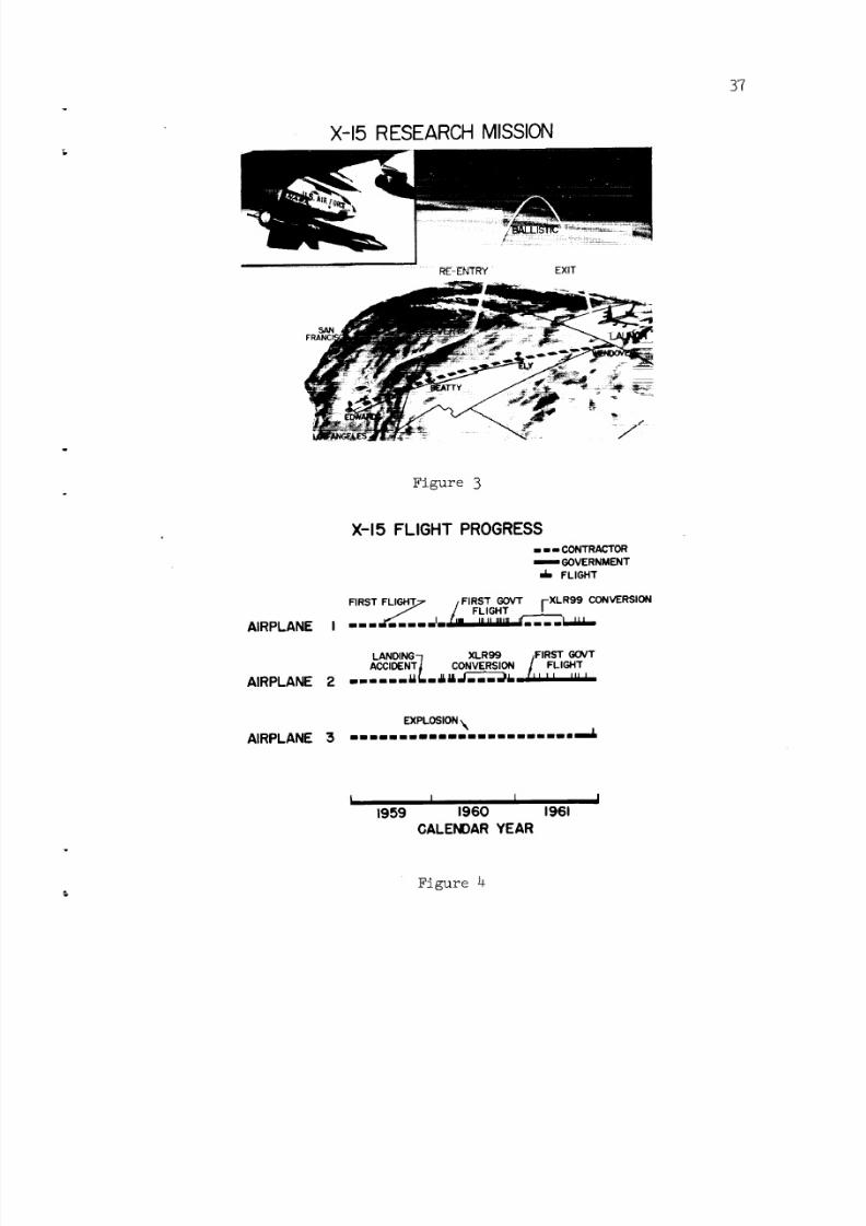
8/7/2019 Review of the X-15 Program
http://slidepdf.com/reader/full/review-of-the-x-15-program 39/56
X-15 RESEARCH MISSION
3'7
EXIT
Figure 3
X-15 FLIGHT PROGRESS
====== CONTRACTOR
"J- FLIGHT
FIRST FLIGHT7 /FIRST GOVT I-XLR99 CONVERSION/ ,/ FLIGHT I
AIRPLANE I ----_- .... E-'rai-'a'l_ .... L-UJ--
LANDING-/ XLR99 #FIRST GOVTACCIDENTj CONVERSION l FLIGHT
AIRPLANE 2 - ..... _'-&=__-' ..... " '
EXPLOSION \AIRPLANE 3, ........................__.L
t I I I1959 1960 1961
GALENOAR YEAR
Figure 4

8/7/2019 Review of the X-15 Program
http://slidepdf.com/reader/full/review-of-the-x-15-program 40/56
38
X-15 PERFORMANCE ENVELOPE
ALTITUDE,FT
250 x 105 XLR99 \
I PREDmCTED--_2001- _LR_I _ \
/ \PREDICTED t \
, or \
I005O
0 I 2 3 4 5 6 7xlO 3VELOCITY, FT/SEC
Figure 5
Iroco
COMPARISON OF PREDICTED AND FLIGHT MEASUREMENTS
TYPICAL FUSELAGE SURFACE TEMPERATURESTATION 26 BOTTOM CENTERLtNE
1200
I000
800
TEMPERATURE, 600• F
4O0
2OO
THEORY WITH /_THEORY WITHOUTWIND-TUNNEL /WIND-TUNNEL
FAC TORS--'--_/,_ FACTORS
// 4 _ /_MEASUREO FLIGHT
/1/o_O O-o_.X TEST
I00 200 300 400
TIME AFTER LAUNCH, SEC
Figure 6
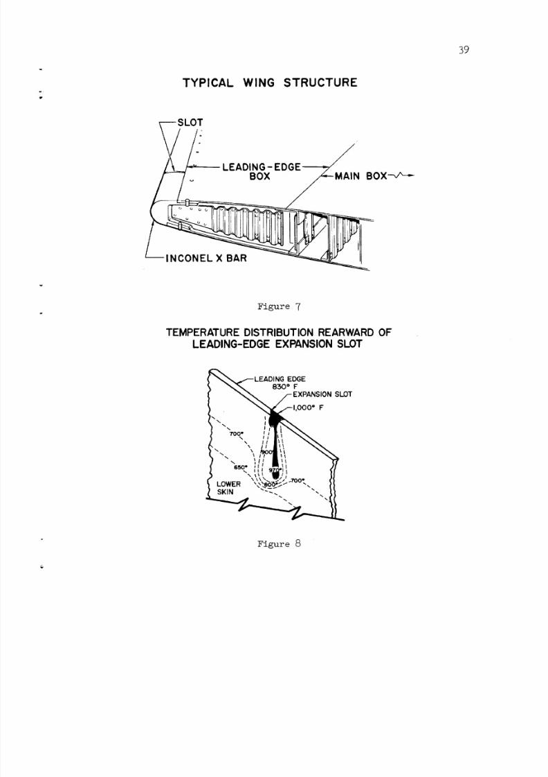
8/7/2019 Review of the X-15 Program
http://slidepdf.com/reader/full/review-of-the-x-15-program 41/56
TYPICAL WING STRUCTURE
39
Figure 7
TEMPERATURE DISTRIBUTION REARWARD OFLEADING-EDGE EXPANSION SLOT
_LEADING EDGE
'_ _ e3o o F
7oo- ', _ _",, ii _t \\
\ _l! !l 17650_ '' I , _'[[
/
LOWER X,\_.,.8__O_t"' vv'_.,I SKIN _._ "-,.
Figure 8

8/7/2019 Review of the X-15 Program
http://slidepdf.com/reader/full/review-of-the-x-15-program 42/56
4O
WING SKIN BUCKLE FOLLOWING .....................
FLIGHT TO MMAX=5.28
_5"
--SKINt
ORIGINAL _ l
SLOT
MODIFIED
LEADING EDGE
I
ro(3
--4
Figure 9
DAMAGED WINDSHIELD GLASS FOLLOWINGFLIGHT TO 217,000 FEET ALTITUDE
Figure i0

8/7/2019 Review of the X-15 Program
http://slidepdf.com/reader/full/review-of-the-x-15-program 43/56
DAMAGED WINDSHIELD GLASS FOLLOWING
FLIGHT TO MMAx = 6.04
41
[,-_.cOoJ
!
Figure ii
VERTICAL TAIL IN B-52 WINGCUTOUT
Figure 12
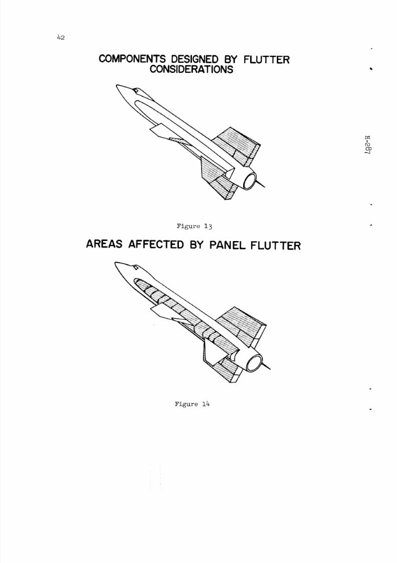
8/7/2019 Review of the X-15 Program
http://slidepdf.com/reader/full/review-of-the-x-15-program 44/56
42
COMPONENTS DESIGNED BY FLUTTERCONSIDERATIONS
!roco
Figure 13
AREAS AFFECTED BY PANEL FLUTTER
Figure 14

8/7/2019 Review of the X-15 Program
http://slidepdf.com/reader/full/review-of-the-x-15-program 45/56
43
b-.-O9
i
1.0
RELATIVEPANEL RESPONSE .5
0
X-15 PANEL RESPONSE
I I I I I ' i I " I200 400 600 800 I000
q, LB/SQ FT
Figure 15
MAIN-GEAR SHOCK-STRUT FORCE AND TRAVEL
SHOCK- STRUTTRAVEL,
IN.
SHOCK- STRUTFORCE,
LB
aO=8=, Vvo-3 FT/SEC, W=14,500 LB
MAIN-GEAR NOSE-GEAR SECONDTOUCHDOWN TOUCHDOWN REACTION
R E L AT ' V E _#//_///HHWJH//_/li_ -- - _/H/t/t/HHH//HHH/_WIND
SECONO601103 PEAK
30 l F,RST _ -
/ PEAK _'1 v
I 'r"--'T_'--i i_ i I I I0 .2 .4 .6 .8 1.0 1.2 1.4
TIME AFTER MAIN-GEAR TOUCHDOWN,SEC
Figure 16$

8/7/2019 Review of the X-15 Program
http://slidepdf.com/reader/full/review-of-the-x-15-program 46/56
44
EFFECT OF MACH NUMBER ON THE TRIMMEDMAXIMUM LIFT-TO-DRAG RATIO
POWER OFF
4
S_PERSONIC THEORY:5 ............
_NEL
(L/D)ma x 2
I | I
2 :5 4M
IFOCO
--.3
Figure 17
CN a ,PERDEG
dC m
dC N
SUMMARY OF LONGITUDINAL STABILITY
.08
.04
0
-if0
o FLIGHT-- WINDTUNNEL. ... THEORY
0<(2<6 =
o
I I I
M
6°<(Z<12 °
f I I i
I I I
0 2 4 6M
Figure 18
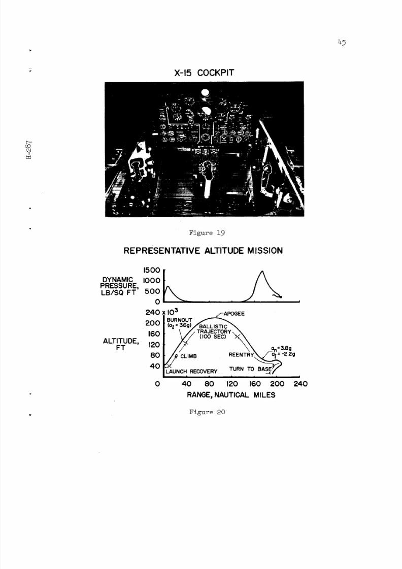
8/7/2019 Review of the X-15 Program
http://slidepdf.com/reader/full/review-of-the-x-15-program 47/56
45
X-15 COCKPIT
[-.-COOJ
!
Figure 19
REPRESENTATIVE ALTITUDE MISSION
DYNAMIC
PRESSURE,LB/SQ FT
ALTITUDE,FT
1500
I000
500
0
240
200
160
120
80
40
0
x tO 3BURNOUT _POGEE
// ..... _\ __=3.BQ
ill I I I I
40 80 120 160 200
RANGE, NAUTICAL MILES
!
240
. Figure 20

8/7/2019 Review of the X-15 Program
http://slidepdf.com/reader/full/review-of-the-x-15-program 48/56
SUMMARY OF X-15 LANDING PATTERN
lOx
0
LATERAL DISTANCE I0FROM TOUCHDOWN,
FT 20
30
40 TYPICAL APPROACH
ALTITUDE,FT
I RANGEOF FLIGHT DATA30
20
I0
oi20 0 20 40XlO 3
LONGITUDINAL DISTANCEFROM TOUCHDOWN, FT
Figure 21
Iro
X-15 TOUCHDOWN AND SLIDEOUT DISTANCES
LONG 4xlO 3
LONGITUDINAL [
TOUCHDOWN 0DISPERSION,
FT
SHORT 4 ' '
8xlO 3
SLIDEOUT,FT 4 f °°°
0
140
0 0o ooo°
_ °°° o0 0
I I I I = I
O0
0
' 16o' ,8o' 266'2 _0TOUCHDOWN, KIAS
Figure 22
=

8/7/2019 Review of the X-15 Program
http://slidepdf.com/reader/full/review-of-the-x-15-program 49/56
47
cooJ
I
45
t5<_.:_ 40
_ 351-
_m 25OC
20
BASELINE HUMAN ENGINEERING DATA
AVERAGE FROM 8 X-15 FLIGHTS
170
160
150
140
130
1200
o HEART RATE I
[] RESPIRATION RATE I
, /,
1
LAUNCH J BURNOUT--_
I_ L ....
I
LANDING--'
!00 200 300 400 500 600 700 800 900
TIME, SEC
Figure 23
X-15 SIMULATION
= Figure 24

8/7/2019 Review of the X-15 Program
http://slidepdf.com/reader/full/review-of-the-x-15-program 50/56
48
XLR99 ALTITUDE-MISSION PROFILE
ALTITUDE,FT
200xl
160
120
8O
4O
03 ,oo',,,',,,PITCH _ I --BURNING TIMEATTITUDE
TIME FROM 60/_'/7 210
LAUNCH' SEC40_J
oJ 24_
, , _ ' , 6 ioI 2 4 5 x
VELOCITY, FT/SEC
Figure 25
X-15 GROUND-MONITOREDENERGY-MANAGEMENT DISPLAY
f
"o
Figure 26
i _ilz
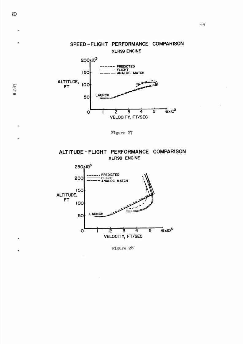
8/7/2019 Review of the X-15 Program
http://slidepdf.com/reader/full/review-of-the-x-15-program 51/56
_D
49
p.-cocU
I
SPEED -FLIGHT
200
150
ALTITUDE,FT I00
50
0
,,o3
PERFORMANCE
XLR99 ENGINE
...... PREDICTEDFLIGHTANALOG MATCH
I I i I I
I 2 3 4 5
VELOCITY, FT/SEC
COMPARISON
J
6xlO3
Figure 27
ALTITUDE - FLIGHT
250:103
PERFORMANCE
XLR99 ENGINE
COMPARISON
200
15C
ALTITUDE,FT
IOO
50
0
...... PREDICTED
FLIGHT \%,_.... ANALOG MATCH _ '_
I I i I I
I 2 3 4 5
VELOCITY, FT/SEC
!
6xlO3
, Figure 28

8/7/2019 Review of the X-15 Program
http://slidepdf.com/reader/full/review-of-the-x-15-program 52/56
5o
=
X-15 EXPLOSION SCENE
Iro
Figure 29
AIRPLANE TEST-SITEENGINE RUN
Figure 30
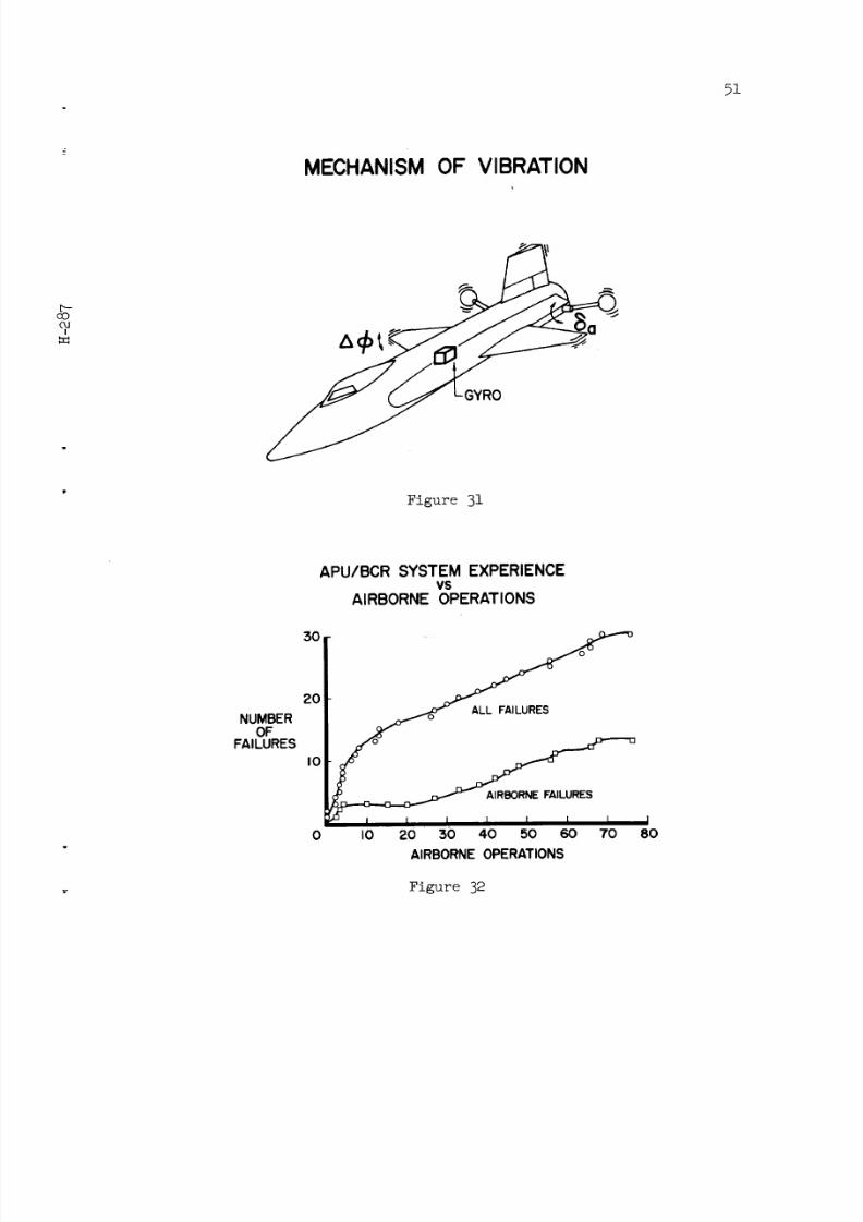
8/7/2019 Review of the X-15 Program
http://slidepdf.com/reader/full/review-of-the-x-15-program 53/56
51
MECHANISM OF VIBRATION
c_OoJ
I
Figure 31
APU/BCR SYSTEM EXPERIENCEvs
AIRBORNE OPERATIONS
NUMBEROF
FAILURES
3oI
I_ I L I I I I I0 I0 20 30 40 50 60 70
AIRBORNE OPERATIONS
I8O
Figure 32
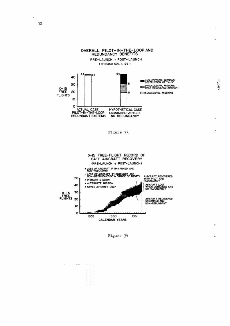
8/7/2019 Review of the X-15 Program
http://slidepdf.com/reader/full/review-of-the-x-15-program 54/56
.52
OVERALL PILOT-IN-THE-LOOP AND
REDUNDANCY BENEFITSPRE-LAUNCH + POST- LAUNCH
(THR OUGH NOV. I , 1961)
X-15FREE
FLIGHTS
44==== 4340"
30"
20"
10
0ACTUAL CASE
PILOT-IN-THE-LOOPREDUNDANT SYSTEMS
UI:.b/MUL, I I UN U#" A--IO
UNSUCCESSFUL MISSIONS;ONLY RECOVERED AIRCRAFT
SUCCESSFUL MISSIONS
HYPOTHETICAL CASEUNMANNEDVEHICLE
NO REDUNDANCY
Figure 33
X-15 FREE-FLIGHT RECORD OFSAFE AIRCRAFT RECOVERY
(PRE-LAUNCH + POST-LAUNCH), eLOSS OFAIRCRAFT IF UNMANNED AND
NON-REDUNDANT
o LOSS OF AJRCRAFT IF UNMANNED ANDNON-REDUNDANT(S0% CHANCE OF ABORT) AI RCRAFT RECOVERED
50 r o PRIMARY MISSION WITH PILOT AND
40 • ALTERNATE MISSION /.._ JI AIRCRAFT LOST• SAVED AIRCRAFT ONLY _ | ) WHEN UNMANNED AND
X- 15 30 )FREE
FLIGHTS 20 _ \ _ AIRCRAFT RECOVERED._mll_ _---_--, UNMANNED AND
lO _ i NON-REDUNDANT
o ............ i,,1959 1960 1961
CALENDAR YEARS
Figure 34
: i

8/7/2019 Review of the X-15 Program
http://slidepdf.com/reader/full/review-of-the-x-15-program 55/56
53
X-15 INSTRUMENT-COMPARTMENT MODIFICATION
("SKYLIGHT")
F
Figure 35
NASA-Langley, 1962 H-287

8/7/2019 Review of the X-15 Program
http://slidepdf.com/reader/full/review-of-the-x-15-program 56/56